Tag Archives: Amazon MQ*

Build priority-based message processing with Amazon MQ and AWS App Runner

Post Syndicated from Aritra Nag original https://aws.amazon.com/blogs/architecture/build-priority-based-message-processing-with-amazon-mq-and-aws-app-runner/

Organizations need message processing systems that can prioritize critical business operations while handling routine tasks efficiently. When handling time-sensitive tasks like rush orders from key customers, critical system alerts, or multi-step business processes, you need to prioritize urgent messages while making sure other routine requests are processed reliably.

In this post, we show you how to build a priority-based message processing system using Amazon MQ for priority queuing, Amazon DynamoDB for data persistence, and AWS App Runner for serverless compute. We demonstrate how to implement application-level delays that high-priority messages can bypass, create real-time UIs with WebSocket connections, and configure dual-layer retry mechanisms for maximum reliability.

This solution addresses three critical challenges in modern data processing systems:

  • Implementing configurable delay processing at the application level
  • Supporting priority-based message routing that respects business requirements
  • Providing real-time feedback to users through WebSocket connections

The use of AWS managed services reduces operational complexity, so teams can focus on business logic rather than infrastructure management. Message handling with priority-based processing makes sure operations receive attention while routine tasks are processed in the background. Users will experience status updates that provide visibility into their requests, while retry mechanisms provide reliability during failures. The infrastructure as code (IaC) approach supports deployments across different environments, from development through production.

Solution overview

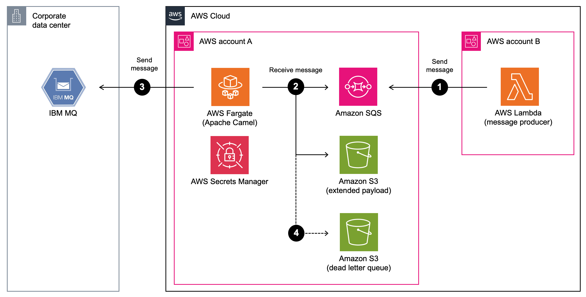
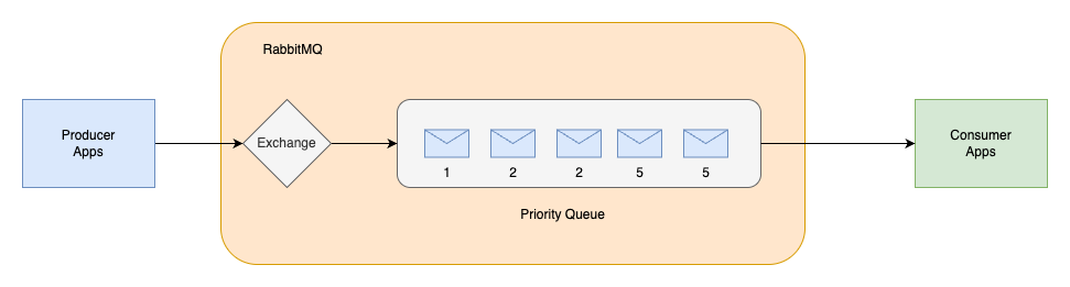
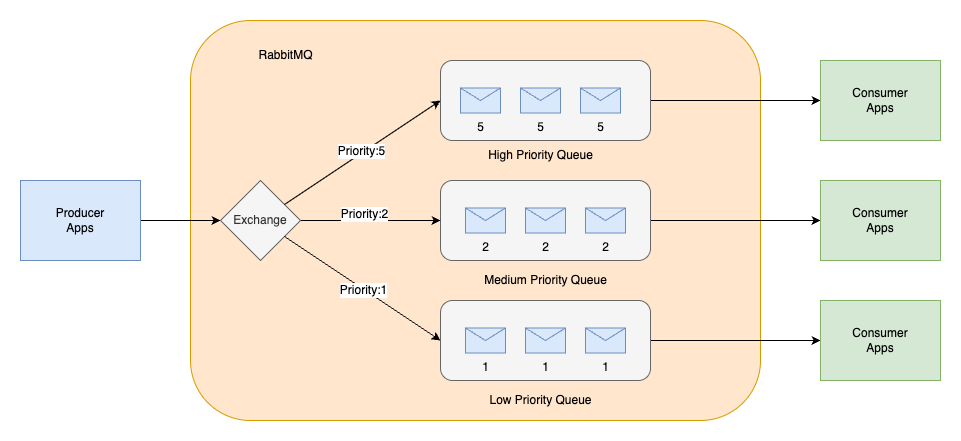
The solution consists of several AWS managed services to create a serverless, priority-based message processing system with real-time user feedback. The architecture implements intelligent routing based on three message priority levels, to make sure critical messages receive immediate processing:

  • High-priority path – Messages bypass delays and queue immediately with JMS priority 9
  • Standard-priority path – Messages undergo configured delays before queuing with JMS priority 4
  • Low-priority path – Messages process after all higher priority messages with JMS priority 0

The following diagram illustrates this architecture.

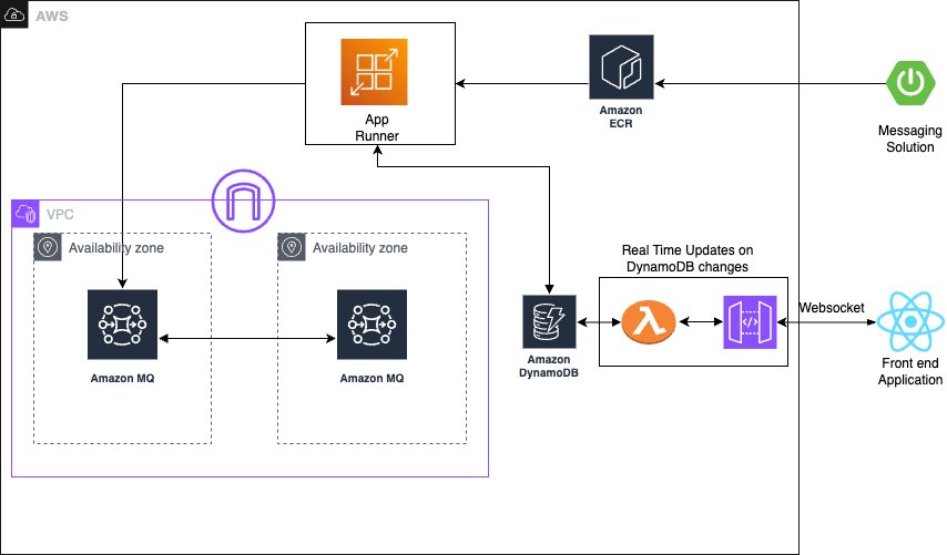
The solution uses the following AWS managed services to deliver a scalable, serverless architecture:

  • AWS App Runner is a fully managed container application service that automatically builds, deploys, and scales containerized applications. It provides automatic scaling based on traffic, built-in load balancing and HTTPS, seamless integration with container registries, and zero infrastructure management overhead.
  • Amazon MQ is a managed message broker service for Apache ActiveMQ that offers priority-based message queuing, automatic failover for high availability, message persistence and durability, and JMS protocol support for enterprise applications.
  • Amazon DynamoDB is a fully managed NoSQL database service providing single-digit millisecond performance at any scale, automatic scaling with on-demand pricing, built-in security and backup capabilities, and global tables for multi-Region deployments.

The system uses JMS priority levels with High=9, Medium=4, and Low=0 for automatic ordering, combined with conditional delay processing based on priority classification. Amazon MQ provides reliable message delivery and persistence with dead-letter queue (DLQ) configuration for failed message handling.

Asynchronous delay processing uses CompletableFuture implementation for non-blocking delays, thread pool management for concurrent processing, graceful error handling with retry mechanisms, and configurable delay periods per message type to optimize resource utilization. For real-time status updates, the solution provides WebSocket connections for bidirectional communication, Amazon DynamoDB Streams for change data capture (CDC), comprehensive status tracking throughout the processing lifecycle, and a React frontend integration for live updates, so users have complete visibility into their message processing status.

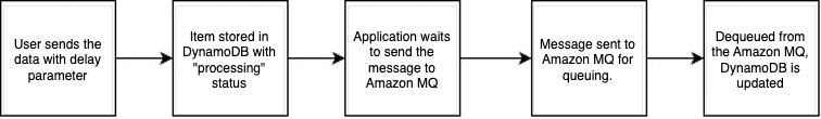
The standard priority messaging flow (shown in the following diagram) handles messages with configurable delays using JMS asynchronous processing capabilities. Messages wait for their specified delay period before entering the Amazon MQ queue, where they’re processed.

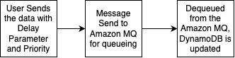
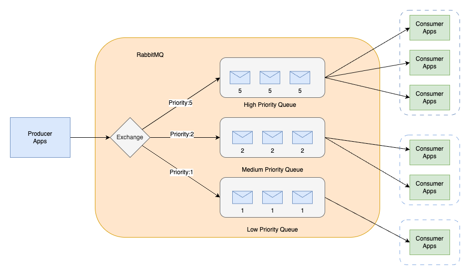
The high-priority messaging flow (shown in the following diagram) provides an express lane for critical messages. These messages skip the delay mechanism entirely and proceed directly to the queue, providing immediate processing for time-sensitive operations.

To make it even more straightforward to get started, we’ve prepared an example application that you can use to observe the Amazon MQ behavior with varying message volumes. You can find the source code repository, IaC implementation, and instructions to run the sample on GitHub.

In the following sections, we walk you through deploying the complete processing system.

Prerequisites

Make sure you have the following tools, permissions, and knowledge to successfully deploy the priority-based message processing system. You must have an active AWS account with the following configurations:

# JSON
{
  "Version": "2012-10-17",
  "Statement": [
    {
      "Effect": "Allow",
      "Action": [
"apprunner:CreateService",
"apprunner:UpdateService",
"apprunner:DeleteService"
      ],
      "Resource": "arn:aws:apprunner:*:*:service/reactive-demo-*"
    },
    {
      "Effect": "Allow",
      "Action": [
"mq:SendMessage",
"mq:ReceiveMessage",
"mq:DeleteMessage"
      ],
      "Resource": "arn:aws:mq:*:*:broker/reactive-demo-broker/*"
    },
    {
      "Effect": "Allow",
      "Action": [
"dynamodb:PutItem",
"dynamodb:GetItem",
"dynamodb:UpdateItem",
"dynamodb:Query"
      ],
      "Resource": "arn:aws:dynamodb:*:*:table/reactive-items*"
    }
  ]
}

Install and configure the following development tools on your local machine:

To successfully implement this solution, you should have basic familiarity with the following:

  • Spring Boot applications
  • Message queue concepts
  • WebSocket protocols
  • React development

Configure the infrastructure stack

This step involves creating the core AWS services using the AWS Cloud Development Kit (AWS CDK). This modular approach enables independent stack management and environment-specific configurations.

  1. Create a new AWS CDK project:
# Bash
mkdir priority-processing && cd priority-processing
cdk init app --language python
pip install aws-cdk-lib constructs
  1. Create the infrastructure stack:
# Python
from aws_cdk import (
    Stack,
    aws_dynamodb as dynamodb,
    aws_amazonmq as mq,
    aws_kms as kms,
    Duration,
    RemovalPolicy,
    CfnOutput
)
from constructs import Construct

class MessageProcessingStack(Stack):
    def __init__(self, scope: Construct, construct_id: str, **kwargs) -> None:
super().__init__(scope, construct_id, **kwargs)

# Create KMS key for encryption
self.kms_key = kms.Key(
    self, "ProcessingKey",
    description="Key for message processing encryption",
    enable_key_rotation=True
)

# DynamoDB table with comprehensive configuration
self.items_table = dynamodb.Table(
    self, "ItemsTable",
    table_name="reactive-items",
    partition_key=dynamodb.Attribute(
name="id",
type=dynamodb.AttributeType.STRING
    ),
    stream=dynamodb.StreamViewType.NEW_AND_OLD_IMAGES,
    billing_mode=dynamodb.BillingMode.ON_DEMAND,
    encryption=dynamodb.TableEncryption.CUSTOMER_MANAGED,
    encryption_key=self.kms_key,
    point_in_time_recovery=True,
    removal_policy=RemovalPolicy.DESTROY
)

# Add Global Secondary Index for status queries
self.items_table.add_global_secondary_index(
    index_name="StatusIndex",
    partition_key=dynamodb.Attribute(
name="status",
type=dynamodb.AttributeType.STRING
    ),
    sort_key=dynamodb.Attribute(
name="createdAt",
type=dynamodb.AttributeType.STRING
    )
)

# Amazon MQ broker configuration
self.mq_broker = mq.CfnBroker(
    self, "MessageBroker",
    broker_name="reactive-demo-broker",
    engine_type="ACTIVEMQ",
    engine_version="5.18",
    host_instance_type="mq.t3.micro",
    deployment_mode="SINGLE_INSTANCE",
    publicly_accessible=False,
    logs=mq.CfnBroker.LogListProperty(
audit=True,
general=True
    ),
    encryption_options=mq.CfnBroker.EncryptionOptionsProperty(
use_aws_owned_key=False,
kms_key_id=self.kms_key.key_id
    ),
    users=[mq.CfnBroker.UserProperty(
username="admin",
password="SecurePassword123!",
console_access=True
    )]
)

# Output values for application configuration
CfnOutput(self, "TableName", 
    value=self.items_table.table_name,
    description="DynamoDB table name")
CfnOutput(self, "MQBrokerEndpoint",
    value=self.mq_broker.attr_amqp_endpoints[0],
    description="Amazon MQ broker endpoint")
  1. Run the following commands to deploy the stack:
# Bash
cdk bootstrap
cdk deploy MessageProcessingStack

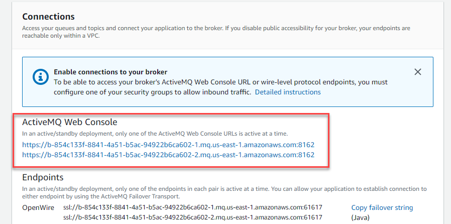
You can verify the infrastructure on the AWS Management Console.

Configure the message processing application

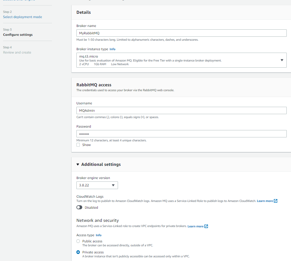
In this step, we create the Spring Boot application with priority-based message processing capabilities. First, we configure the application.properties file to incorporate environment variables, including AWS credentials, AWS Regions, and other configuration parameters such as log levels into the application and business logic implementation. Next, we implement the message service using a JMS template with comprehensive error handling, followed by enhancing the JMS configuration with connection pooling for improved performance.

The following code illustrates an example message service implementation:

// Example message service implementation
@Service
public class MessageService {
    @Autowired
    private JmsTemplate jmsTemplate;
    
    public void sendPriorityMessage(Message message) {
jmsTemplate.send(session -> {
    Message jmsMessage = session.createTextMessage(message.getContent());
    jmsMessage.setJMSPriority(message.getPriority());
    return jmsMessage;
});
    }
}

For proper timestamp update implementation, we integrate the DynamoDB SDK service with caching capabilities. Finally, after implementing the REST controller for the API with asynchronous processing support, we can deploy the message processing application. This implementation includes Java code application-level delay processing for demonstration purposes. Although this approach effectively showcases the priority-based message routing capabilities and real-time WebSocket updates in our demo environment, AWS recommends using Amazon MQ delay processing features for production workloads. For production implementations, use Amazon MQ delay and scheduling capabilities instead of application-level delays through features like Amazon MQ delay queues, ActiveMQ scheduling features, and appropriate message Time-to-Live (TTL) configurations.

The following code is an example snippet showcasing the Amazon MQ feature:

// Create connection factory with Amazon MQ endpoint
ActiveMQConnectionFactory factory = new ActiveMQConnectionFactory(brokerUrl);
factory.setUserName("admin");
factory.setPassword("your-password");
try (Connection connection = factory.createConnection();
     Session session = connection.createSession(false, Session.AUTO_ACKNOWLEDGE)) {
    
    // Create destination and producer
    Destination destination = session.createQueue(queueName);
    MessageProducer producer = session.createProducer(destination);
    
    // Create message
    TextMessage message = session.createTextMessage(messageContent);
    
    // Set native delay using ActiveMQ scheduled delivery
    message.setLongProperty(ScheduledMessage.AMQ_SCHEDULED_DELAY, delayMillis);
    
    // Optionally set priority for delayed message
    message.setJMSPriority(4);
    
    // Send the message - it will be delivered after the specified delay
    producer.send(message);
}

Build and deploy the Spring Boot application to App Runner

In this step, we push the application to Amazon Elastic Container Registry (Amazon ECR) to run it in App Runner:

  1. Build and push the Docker image to Amazon ECR:
# Bash

# Build the Docker image
docker build -t reactive-demo .

# Create ECR repository
aws ecr create-repository --repository-name reactive-demo --region us-east-1

# Get login token and login to ECR
aws ecr get-login-password --region us-east-1 | docker login --username AWS --password-stdin $ECR_URI

# Tag and push image
ECR_URI=$(aws ecr describe-repositories --repository-names reactive-demo --query 'repositories[0].repositoryUri' --output text)
docker tag reactive-demo:latest $ECR_URI:latest
docker push $ECR_URI:latest
  1. Create the App Runner service with environment variables for the DynamoDB table and Amazon MQ broker endpoint:
# Python

from aws_cdk import (
    aws_apprunner as apprunner,
    aws_iam as iam
)

class AppRunnerStack(Stack):
    def __init__(self, scope: Construct, id: str, 
 table_name: str, mq_endpoint: str, **kwargs):
super().__init__(scope, id, **kwargs)

# Create IAM role for App Runner
app_runner_role = iam.Role(
    self, "AppRunnerRole",
    assumed_by=iam.ServicePrincipal("tasks.apprunner.amazonaws.com"),
    managed_policies=[
iam.ManagedPolicy.from_aws_managed_policy_name(
    "AmazonDynamoDBFullAccess"
),
iam.ManagedPolicy.from_aws_managed_policy_name(
    "AmazonMQFullAccess"
)
    ]
)

# Create App Runner service
self.service = apprunner.CfnService(
    self, "ReactiveProcessingService",
    service_name="reactive-processing-service",
    source_configuration=apprunner.CfnService.SourceConfigurationProperty(
authentication_configuration=apprunner.CfnService.AuthenticationConfigurationProperty(
    access_role_arn=app_runner_role.role_arn
),
image_repository=apprunner.CfnService.ImageRepositoryProperty(
    image_identifier=f"{ECR_URI}:latest",
    image_configuration=apprunner.CfnService.ImageConfigurationProperty(
port="8080",
runtime_environment_variables=[
    {"name": "DYNAMODB_TABLE_NAME", "value": table_name},
    {"name": "MQ_BROKER_URL", "value": mq_endpoint}
]
    ),
    image_repository_type="ECR"
)
    ),
    health_check_configuration=apprunner.CfnService.HealthCheckConfigurationProperty(
path="/actuator/health",
protocol="HTTP",
interval=10,
timeout=5,
healthy_threshold=1,
unhealthy_threshold=5
    ),
    instance_configuration=apprunner.CfnService.InstanceConfigurationProperty(
cpu="0.5 vCPU",
memory="1 GB"
    )
)

Set up real-time updates

For this step, we implement WebSocket support for real-time status updates using AWS Lambda to process DynamoDB streams and send updates to connected clients using Amazon API Gateway WebSocket connections. You can find the code snippet for this in this link

Deploy the React application to Amazon S3 and Amazon CloudFront

In this step, we create a frontend application to enable the WebSocket connection for seeing the messaging getting updated in the DynamoDB and API Gateway WebSocket connections.

Similar to the above section, here is the AWS cdk code for building the frontend for proceeding towards the validation of the solution

Validate the solution

This section provides comprehensive testing procedures to validate the priority-based message processing system.

Automated testing script

After you have completed the preceding steps, you can initiate a comprehensive testing script to validate priority processing and delay behavior:

# Bash
#!/bin/bash
curl -X POST "$API_URL/api/items" \
  -H "Content-Type: application/json" \
  -d '{
    "title": "High Priority Task",
    "priority": "High",
    "delay": 10
  }'

Validation through the web interface

The following screenshot of the UI illustrates how the queueing mechanism can work with the real-time updates using WebSockets.

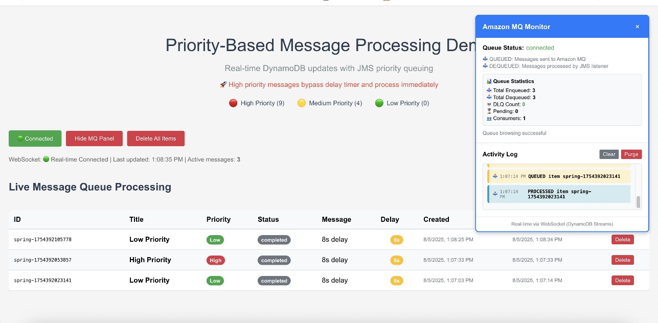
The web interface provides validation of the priority-based message processing system. Access the Amazon CloudFront URL to view the following information:

  • Real-time message processing with live status updates
  • Queue statistics showing message distribution by priority
  • Processing timeline demonstrating priority bypass behavior
  • WebSocket connection status indicating real-time connectivity

Amazon CloudWatch dashboards and alarms

AWS recommends creating Amazon CloudWatch dashboards to track your priority-based message processing system’s performance across multiple dimensions. Monitor message processing by priority levels to make sure high-priority messages are processed first and identify any bottlenecks in your priority routing logic. The following screenshot shows an example dashboard.

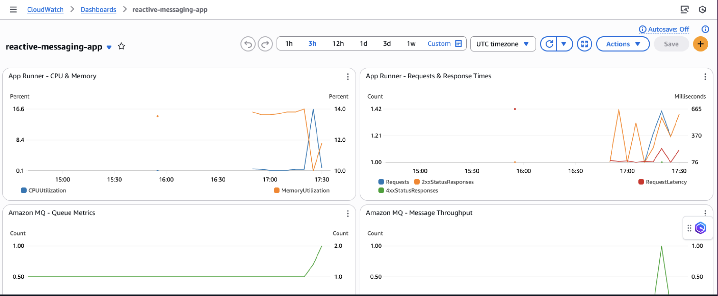
You can track queue depth and processing times to understand system load and latency patterns, helping you optimize resource allocation and identify when scaling is needed. Observe DynamoDB performance metrics including read/write capacity consumption, throttling events, and latency to make sure your database layer maintains optimal performance under varying loads.

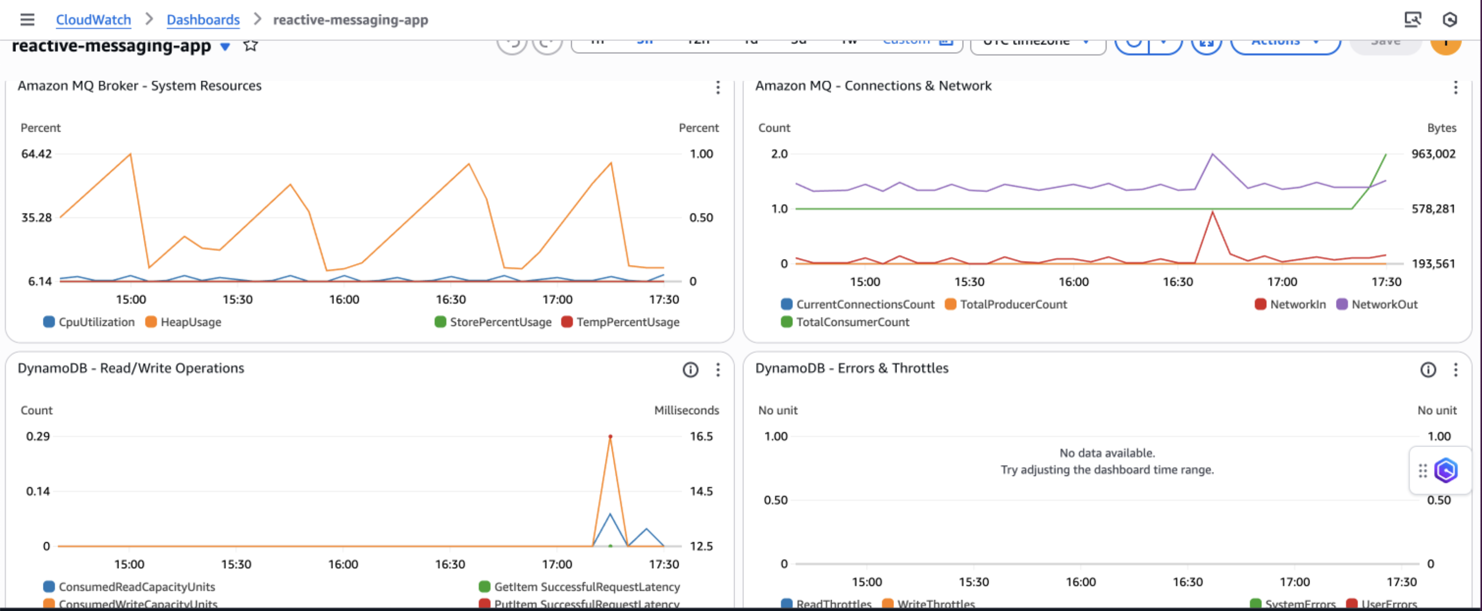
Additionally, implement application-specific custom metrics such as message processing success rates, retry counts, and business-specific KPIs to gain deeper insights into your application’s behavior and make data-driven decisions for continuous improvement.

Security considerations

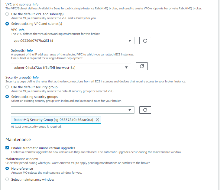
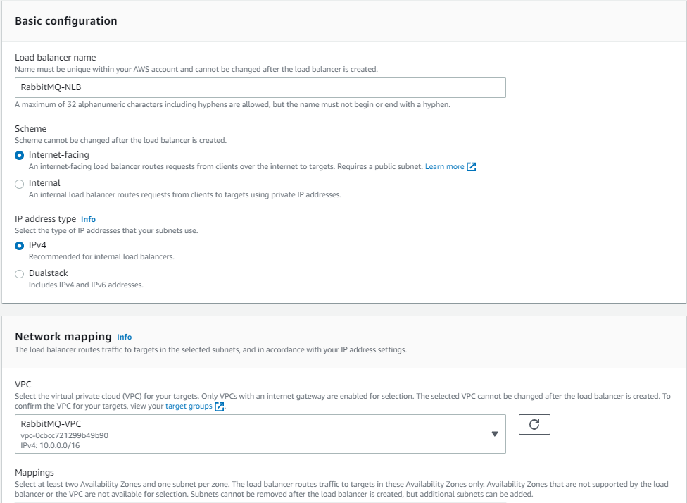
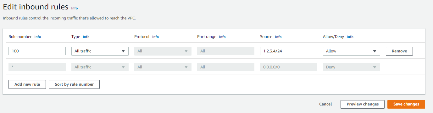
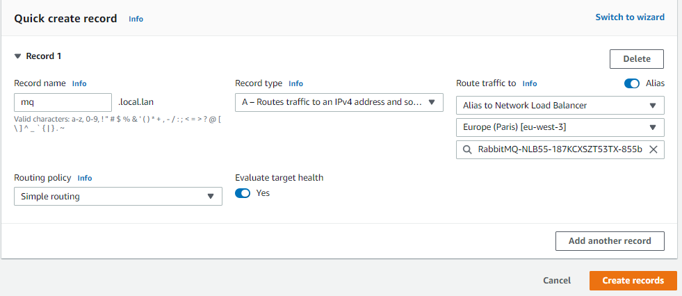
AWS recommends implementing comprehensive security measures to safeguard your message processing system. Start by implementing least privilege IAM policies that grant only the minimum permissions required for each component to function, making sure services like App Runner can only access the specific DynamoDB tables and Amazon MQ queues they need. Configure your network architecture using a virtual private cloud (VPC) with private subnets for Amazon MQ, isolating your message broker from direct internet access while maintaining connectivity through NAT gateways for necessary outbound connections.

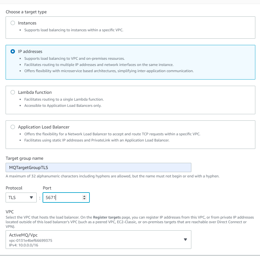
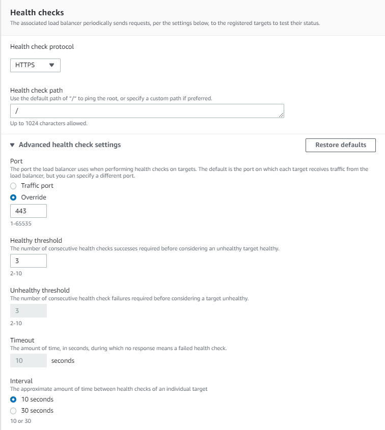
Enable encryption at rest using AWS Key Management Service (AWS KMS) for DynamoDB tables and Amazon MQ data and enforce encryption in transit by configuring SSL/TLS connections for all service communications, particularly for ActiveMQ broker connections. Finally, configure security groups with minimal access rules that explicitly define allowed traffic between components, restricting inbound connections to only the ports and protocols required for your application to function, such as port 61617 for ActiveMQ SSL connections from App Runner instances.

Cost considerations

The following table contains cost estimates based on the US East (N. Virginia) Region. Actual costs might vary based on your Region, usage patterns, and pricing changes.

Service Small (1,000 msg/day) Medium (10,000 msg/day) Large (100,000 msg/day)
Amazon DynamoDB $5–10 $25–50 $200–400
Amazon MQ $15 (t3.micro) $30 (m5.large) $120 (m5.xlarge)
AWS App Runner $20–40 $50–150 $400–800
Amazon API Gateway WebSocket $3–5 $10–25 $50–100
Amazon CloudWatch Logs $5–10 $10–20 $30–50
Data Transfer $5 $10-20 $50-100
Total Estimated Cost $53–95 $135–295 $850–1,570

Troubleshooting

The following are common issues and their solutions when implementing the priority-based message processing system:

  • Messages not processing in priority order:
    • Verify JMS priority is configured correctly: message.setJMSPriority(priority)
    • Check ActiveMQ broker configuration for priority queue support
    • Confirm CLIENT_ACKNOWLEDGE mode is properly configured
    • Review queue consumer concurrency settings
  • WebSocket updates not working:
    • Verify DynamoDB Streams is enabled on the table
    • Check the Lambda function is triggered by stream events
    • Validate API Gateway WebSocket configuration and IAM permissions
    • Test the WebSocket connection using browser developer tools
  • Application scaling issues:
    • Monitor App Runner metrics in CloudWatch
    • Adjust auto scaling configuration based on traffic patterns
    • Consider Amazon MQ broker capacity and upgrade if needed
    • Review DynamoDB capacity settings and enable auto scaling

Clean up

To avoid incurring ongoing AWS charges, delete the resources you created in this walkthrough:

  1. Delete the CDK stacks:
cdk destroy MessageProcessingStack
cdk destroy FrontendStack
  1. Remove the App Runner service:
aws apprunner delete-service --service-arn <your-service-arn>
  1. Delete the ECR repositories and container images.
  2. Remove CloudWatch log groups if not set to auto-delete.
  3. Delete S3 buckets used for frontend hosting.

Next steps

To extend this solution and add additional capabilities, consider the following enhancements:

Conclusion

This solution demonstrates how to build a production-ready priority-based message processing system using AWS managed services. By combining Amazon MQ priority queuing with DynamoDB real-time streams and App Runner serverless compute, you create a resilient architecture that intelligently handles messages based on business priorities.The implementation of application-level delays with priority bypass makes sure critical messages receive immediate attention, and the dual-layer retry mechanism provides maximum reliability. Real-time WebSocket updates keep users informed of processing status, creating a responsive and transparent system.To learn more about the services and patterns used in this solution, explore the following resources:


About the authors

Implementing message prioritization with quorum queues on Amazon MQ for RabbitMQ

Post Syndicated from Akhil Melakunta original https://aws.amazon.com/blogs/compute/implementing-message-prioritization-with-quorum-queues-on-amazon-mq-for-rabbitmq/

Quorum queues are now available on Amazon MQ for RabbitMQ from version 3.13. Quorum queues are a replicated First-In, First-Out (FIFO) queue type that uses the Raft consensus algorithm to maintain data consistency. Quorum queues on RabbitMQ version 3.13 lack one key feature compared to classic queues: message prioritization. However, RabbitMQ version 4.0 introduced support for message priority, which behaves differently than classic queue message priorities. Migrating applications from classic queues with message priority to quorum queues on Amazon MQ for RabbitMQ presents challenges for customers. This post describes the different approaches to implementing message prioritization in quorum queues in Amazon MQ for RabbitMQ.

Amazon MQ is a managed message broker service for Apache ActiveMQ and RabbitMQ that simplifies setting up and operating message brokers on AWS.

Why message prioritization matters

Modern messaging systems require handling messages differently, depending on the business priority. Some messages are more time-sensitive or critical than others and prioritizing them can enhance the efficiency and responsiveness of applications. Message prioritization allows certain messages to be processed before others, aligning with business priorities and helping to ensure that high-value or time-critical messages receive the attention they need.

Message prioritization addresses critical business challenges across multiple industries. In insurance companies, it can expedite urgent claim processing by prioritizing high-priority messages over routine policy updates, reducing settlement times. Automotive manufacturers can make sure that critical production line alerts and safety notifications take precedence over standard telemetry data, preventing costly downtime. Energy utilities can prioritize real-time grid stability alerts and outage notifications, enabling faster responses to potential blackouts. By implementing message priority, industries can direct immediate attention to time-sensitive operations while efficiently managing routine processes within existing infrastructure. By using this approach to transform their communication strategies, organizations can respond more quickly and effectively to critical events.

Classic queues compared to quorum queues message prioritization

In this section, explore the fundamental differences between classic queues and quorum queues when it comes to message prioritization capabilities. Examine how each queue type handles message priority, the built-in features available, and key considerations.

Message prioritization with classic queues

In classic queues, RabbitMQ supports message priorities ranging from 1 to 255, with 1 being the lowest priority and 255 being the highest. However, it’s generally recommended to use a smaller range (for example, 1–5) for better performance, because RabbitMQ needs to maintain an internal sub-queue for each priority from 1 up to the maximum value configured for a given queue. A wider priority range adds more CPU and memory cost, which can impact broker performance.

Priority queue behavior in classic queues:

  • Classic queues require x-max-priority argument to define the maximum number of priorities for a given queue
  • A procedure sends a message with a priority property value
  • Consumers don’t need special configuration to handle priorities
  • Messages with higher priority are delivered before messages with lower priority
  • Within the same priority level, messages are delivered in FIFO order
  • Messages without a priority property are treated as if their priority is lowest
  • Messages with a priority that is higher than the queue’s maximum are treated as if they were published with the maximum priority

Example Python code for classic queue implementation with message priority:

#!/usr/bin/env python
import pika
import ssl
# Set up SSL context for secure connection
context = ssl.SSLContext(ssl.PROTOCOL_TLSv1_2)
# Define credentials
credentials = pika.PlainCredentials('username', 'password') # Replace with actual credentials
# Set up connection parameters for Amazon MQ RabbitMQ broker
connection_parameters = pika.ConnectionParameters(
    host='b-example.mq.us-west-2.on.aws', # Replace with actual broker endpoint
    port=5671,
    credentials=credentials,
    ssl_options=pika.SSLOptions(context)
)
# Establish connection and create a channel
connection = pika.BlockingConnection(connection_parameters)
channel = connection.channel()
# Declare a direct exchange
# - direct exchanges route messages based on routing key
channel.exchange_declare(
    exchange='priority_exchange',
    exchange_type='direct',
)
# Declare a priority queue
# - x-max-priority=5 sets maximum priority level (0-5)
# - x-queue-type=classic specifies classic queue implementation
channel.queue_declare(
    queue='classic_priority_queue',
    arguments={
        'x-max-priority': 5,
        'x-queue-type': "classic"
    }
)
# Bind queue to exchange with routing key
# - This connects the queue to the exchange
# - Messages sent to the exchange with matching routing key will be routed to this queue
channel.queue_bind(
    queue='classic_priority_queue',
    exchange='priority_exchange',
    routing_key='priority_queue'
)
# Publish messages with different priorities
# Low priority message (priority=1)
channel.basic_publish(
    exchange='priority_exchange',
    routing_key='priority_queue',
    body='Low priority message',
    properties=pika.BasicProperties(priority=1)
)
print(" [x] Sent 'Low priority message'")
# Medium priority message (priority=2)
channel.basic_publish(
    exchange='priority_exchange',
    routing_key='priority_queue',
    body='Medium priority message',
    properties=pika.BasicProperties(priority=2)
)
print(" [x] Sent 'Medium priority message'")
# High priority message (priority=5)
channel.basic_publish(
    exchange='priority_exchange',
    routing_key='priority_queue',
    body='High priority message',
    properties=pika.BasicProperties(priority=5)
)
print(" [x] Sent 'High priority message'")
# Close the connection
connection.close()

The preceding code demonstrates message prioritization in RabbitMQ using a classic queue with built-in priority handling. The implementation connects to a RabbitMQ broker using the Python Pika library and declares a direct exchange, a classic queue with a maximum priority level of 5. Messages are then published to this single queue with explicitly assigned priority values (1 for low, 2 for medium, and 5 for high priority). When consumers fetch messages from this queue, RabbitMQ will deliver higher priority messages first.

Message prioritization with quorum queues

Unlike classic queues, quorum queues in Rabbit MQ 3.13 don’t support message prioritization natively. However, there are effective patterns that you can implement to achieve message priority with Quorum queues.

Using separate queues for different priorities

A straightforward method is to create multiple quorum queues, each dedicated to different priority levels. For example, you might have a high-priority queue and a low-priority queue. Using RabbitMQ exchange and binding key route messages to the appropriate queues based on their priority, allowing the system to process high-priority messages more promptly, as shown in the following figure.

Example to implement priority handling using separate quorum queues:

#!/usr/bin/env python
import pika
import ssl
# Set up SSL context for secure connection
context = ssl.SSLContext(ssl.PROTOCOL_TLSv1_2)
# Define credentials
credentials = pika.PlainCredentials('username', 'password') #Replace with actual credentials
# Set up connection parameters for Amazon MQ RabbitMQ broker
connection_parameters = pika.ConnectionParameters(
    host='b-example.mq.us-west-2.on.aws',
    port=5671,
    credentials=credentials,
    ssl_options=pika.SSLOptions(context)
)
# Establish connection and create a channel
connection = pika.BlockingConnection(connection_parameters)
channel = connection.channel()
# Declare a direct exchange
# - Direct exchanges route messages based on routing key
channel.exchange_declare(
    exchange='priority_exchange_qq',
    exchange_type='direct'
)
# Create separate quorum queues for different priority levels
# Low priority queue
channel.queue_declare(
    queue='low_priority_queue',
    durable=True,
    arguments={
        'x-queue-type': "quorum" 
    }
)
# Bind the low priority queue to the exchange with a specific routing key
# - This creates a rule that messages sent to 'priority_exchange' with routing_key='low_priority_1'
# - will be routed to the 'low_priority_queue'
channel.queue_bind(
    queue='low_priority_queue',
    exchange='priority_exchange_qq',
    routing_key='low_priority_1'
)
# Medium priority queue
channel.queue_declare(
    queue='medium_priority_queue',
    durable=True,
    arguments={
        'x-queue-type': "quorum" 
    }
)
# Bind the medium priority queue to the exchange with a specific routing key
# - Messages with routing_key='medium_priority_2' will be directed to the 'medium_priority_queue'
channel.queue_bind(
    queue='medium_priority_queue',
    exchange='priority_exchange_qq',
    routing_key='medium_priority_2'
)
# High priority queue
channel.queue_declare(
    queue='high_priority_queue',
    durable=True,
    arguments={
        'x-queue-type': "quorum" 
    }
)
# Bind the high priority queue to the exchange with a specific routing key
# - Messages with routing_key='high_priority_2' will be directed to the 'high_priority_queue'
channel.queue_bind(
    queue='high_priority_queue',
    exchange='priority_exchange_qq',
    routing_key='high_priority_5'
)
# Publish messages to different priority queues
print(" [x] Publishing messages to different priority queues")
# Low priority message
channel.basic_publish(
    exchange='priority_exchange_qq',  
    routing_key='low_priority_1',
    body='Low priority message'
)
print(" [x] Sent 'Low priority message'")
# Medium priority message
channel.basic_publish(
    exchange='priority_exchange_qq', 
    routing_key='medium_priority_2',
    body='Medium priority message'
)
print(" [x] Sent 'Medium priority message'")
# High priority message
channel.basic_publish(
    exchange='priority_exchange_qq', 
    routing_key='high_priority_5',
    body='High priority message'
)
print(" [x] Sent 'High priority message'")
# Close the connection
connection.close()
print(" [x] Connection closed")

The preceding code demonstrates a message prioritization approach in RabbitMQ using separate quorum queues for different priority levels (low, medium, and high). The implementation uses the Python Pika library to connect to a RabbitMQ server, a direct exchange and three separate quorum queues for different priority levels, and publish messages to different routing keys with different priority.

Custom priority logic on consumers

Implement custom logic within your application to handle messages based on their priority. For example, you can use headers or metadata to determine the priority of a message and then use this information to route messages to different queues or handle them in a specific order.

Higher priority queues should use more consumers or consumers with higher resources allocated to process messages more quickly than lower priority queues. Use the basic.qos (prefetch) method in manual acknowledgement mode on your consumers to limit the number of messages that can be out for delivery at any time and allow messages to be prioritized. basic.qos is a value a consumer sets when connecting to a queue. It indicates how many messages the consumer can handle at one time. This method is shown in the following figure.

Note: This solution implements message priority on a best-effort basis. There is a possibility that low and medium priority messages may be processed before high priority messages.

Conclusion

Message prioritization in RabbitMQ brokers on Amazon MQ has different considerations for classic and quorum queues. Using quorum queues requires a thoughtful approach because of the lack of native support for message proritization in RabbitMQ. By employing separate queues and custom logic, you can achieve effective prioritization while maintaining the high availability and consistency that quorum queues offer. Embrace these strategies to optimize your messaging infrastructure, enhance application responsiveness, and make sure that critical messages are processed in a timely manner.

We recommend that you adopt quorum queues as the preferred replicated queue type on RabbitMQ 3.13 brokers. For more details, see Amazon MQ documentation. For more information, see quorum queues.

To learn more, see Amazon MQ for Rabbit MQ.

Improve RabbitMQ performance on Amazon MQ with AWS Graviton3-based M7g instances

Post Syndicated from Vignesh Selvam original https://aws.amazon.com/blogs/big-data/improve-rabbitmq-performance-on-amazon-mq-with-aws-graviton3-based-m7g-instances/

Amazon MQ is a fully managed service for open-source message brokers such as RabbitMQ and Apache ActiveMQ. Today, we are announcing the availability of AWS Graviton3-based Rabbit MQ brokers on Amazon MQ, which runs on Amazon EC2 M7g instances. AWS Graviton processors are custom designed server processors developed by AWS to provide the best price performance for cloud workloads running on Amazon EC2. It uses the Arm (arm64) instruction set. For example, when running an Amazon MQ for RabbitMQ cluster broker using M7g.4xlarge instances, you can achieve up to 50% higher workload capacity and up to 85% higher throughput compared to M5.4xlarge instances. Additionally, M7g brokers on Amazon MQ offer optimized disk sizes for clusters, providing reduction in storage cost savings over M5 brokers depending on the instance size chosen. To learn more, refer to Amazon EC2 M7g instances.

Amazon MQ helps you reduce the operational overhead of using open source message brokers like RabbitMQ while providing security, high availability, and durability. Many organizations use Amazon MQ to decouple applications, asynchronously process messages, and build event-driven architectures. We tested and validated M7g instances for RabbitMQ version 3.13, so you can run your critical messaging workloads on Amazon MQ brokers with improved performance characteristics, while also saving on costs. Amazon MQ supports M7g instances in a wide variety of sizes, ranging from medium to 16xlarge sizes, to suit your different messaging workloads. M7g instances support Amazon MQ for RabbitMQ features, making it straightforward for you to run your existing RabbitMQ workloads with minimal changes. You can get started by provisioning new brokers or upgrading your existing RabbitMQ brokers using Amazon EC2 M5 instances to Graviton3-based M7g instances as the broker type using the AWS Management Console, APIs using the AWS SDK, and the AWS Command Line Interface (AWS CLI).

The following table lists the specific characteristics of M7g instances on Amazon MQ.

M7g specs for Amazon MQ
Instance Name (MQ.m7g.*) vCPUs Memory (GiB) Network Bandwidth
medium 1 4 Up to 12.5 Gb
large 2 8 Up to 12.5 Gb
xlarge 4 16 Up to 12.5 Gb
2xlarge 8 32 Up to 15 Gb
4xlarge 16 64 Up to 15 Gb
8xlarge 32 128 15 Gb
12xlarge 48 192 22.5 Gb
16xlarge 64 256 30 Gb

M7g instances vs. M5 instances on Amazon MQ

Customers can see both performance improvements and cost savings for their RabbitMQ workloads when moving from M5 instances to M7g instances. In terms of performance, you can size your RabbitMQ brokers for workloads by measuring the workload capacity and throughput. Amazon MQ has improved the performance of RabbitMQ on both workload capacity and throughput for M7g instances. In terms of cost, you pay for the instance per hour, disk usage per Gb-month, and data transfer. Amazon MQ has optimized disk sizes to offer cost savings for customers on disk usage. Let’s first examine the performance improvements.

Workload capacity improvements

Workload capacity represents the total number of connections, channels, and queues that you can use without running into memory alarm. The actual usage of these resources is limited by the high memory watermark value. Every resource (for example, a queue) on creation uses up a small amount of memory, but when these resources are used, the memory used increases depending on the number and size of messages processed up until a memory threshold. The RabbitMQ broker goes into memory alarm when the memory used on a node reaches this pre-defined threshold known as high memory watermark. When a broker raises a memory alarm, it will block all connections that are publishing messages. After the memory alarm has cleared (for example, due to delivering some messages to clients that consume and acknowledge the deliveries), normal service resumes. The open source community guidance for RabbitMQ 3.13 is to configure the memory threshold at 40% of the available memory per node. M5 brokers have the memory threshold set at 40% on Amazon MQ.

We evaluated this recommendation across M7g instances and determined that the memory threshold can be increased for instances on Amazon MQ to more than 40% due to the operational improvements by the service, as illustrated in the following figure. This increase in available memory translates to a higher use of resources like queues, channels, and connections within the resource limits of the broker. The change in available memory results in up to 50% improvement in workload capacity for customers when compared to M5 brokers today.

Throughput improvements

The throughput of a broker varies widely with the queue type and usage pattern of customers. Amazon MQ evaluated the throughput capacity of a RabbitMQ three-node cluster broker by measuring the publish throughput in messages per second for 10 quorum queues with a message size of 1 KB and a ratio of 1:20 for connection to channels. We arrived at this benchmark test after evaluating multiple scenarios with the goal of providing you a simple way to estimate the average throughput you can expect from a RabbitMQ broker when following best practices. You can see up to 85% higher throughput compared to equivalent M5 brokers on Amazon MQ, as illustrated in the following figure.

The performance of a RabbitMQ broker depends on the version, queue type, and usage pattern in addition to the infrastructure used. You might see different performance improvements based on your specific usage patterns and resources used. We recommend using the Amazon MQ sizing guidance to size your broker and benchmarking the performance for your specific workload using M7g instances.

Cost savings on cluster disk usage

Customers using M7g brokers in cluster deployment mode are provisioned with a disk volume per node that varies in size depending on the instance size. For M5 brokers, the RabbitMQ brokers were provisioned with a fixed disk volume of 200 GB per node. The open source guidance around disk sizes is to use a size higher than twice the memory threshold. We tested various disk sizes and identified optimal disk sizes that would provide a better operational posture. With this change, customers using M7g cluster brokers on Amazon MQ will get cost savings due to the smaller disk size provisioned per node as compared to equivalent M5 brokers, as shown in the following table. Single-instance M7g brokers will continue to be provisioned with 200 GB of disk size.

Instance size Disk Volume M5 cluster(GB) Disk Volume M7g Cluster(GB) Cost savings for customersM5 vs. M7g (%)
medium 15
large 600 45 92.50%
xlarge 600 75 87.50%
2xlarge 600 135 77.50%
4xlarge 600 270 55.00%
8xlarge 525
12xlarge 780
16xlarge 1035

Pricing and Regional availability

M7g instances are available in AWS Regions where Amazon MQ is available at the time of writing except Africa (Cape Town), Canada West (Calgary), and Europe (Milan) Regions. Refer to Amazon MQ Pricing to learn about the availability of specific instance sizes by Region and the pricing for M7g instances.

Summary

In this post, we discussed the performance gains and cost savings achieved while using Graviton-based M7g instances. These instances can provide significant improvement in throughput and workload capacity compared to similar sized M5 instances for Amazon MQ workloads. To get started, create a new broker with M7g brokers using the console, and refer to the Amazon MQ Developer Guide for more information.


About the authors

Vignesh Selvam is the Principal Product Manager for Amazon MQ at AWS. He works with customers to solve their messaging needs and with the open-source communities for innovating with message brokers. Prior to joining AWS, he built products for security and analytics.

Samuel Massé is a Software Development Engineer at AWS. He has been leading the engineering effort to support M7g on the RabbitMQ team. In his free time he enjoys coding unfinished side projects.

Vinodh Kannan Sadayamuthu is a Senior Specialist Solutions Architect at Amazon Web Services (AWS). His expertise centers on AWS messaging and streaming services, where he provides architectural best practices consultation to AWS customers.

Networking of Amazon MQ for RabbitMQ event source mapping for AWS Lambda

Post Syndicated from Rafal Pawlaszek original https://aws.amazon.com/blogs/compute/networking-of-amazon-mq-for-rabbitmq-event-source-mapping-for-aws-lambda/

Event-driven architectures with message brokers need careful attention to security best practices. Amazon MQ for RabbitMQ combined with AWS Lambda enables serverless event processing. However, implementing defense in depth and least privilege principles necessitates a clear understanding of networking requirements. This is particularly important when working with different subnet types and their impact on service connectivity.

This post explores the networking aspects of Lambda event source mapping for Amazon MQ for RabbitMQ. Learn how deployment options influence your networking setup and security posture to make informed architectural decisions. These networking concepts are essential for building secure, scalable solutions, regardless of your experience level with message brokers.

For clarity in this post, when we refer to “RabbitMQ”, we mean Amazon MQ for RabbitMQ.

Prerequisites

The following prerequisites are necessary to complete this post:

  • An Amazon Web Services (AWS) account
  • Basic understanding of AWS networking concepts
  • Familiarity with Amazon MQ for RabbitMQ
  • Basic knowledge of Lambda

Furthermore, to enable setup of the discussed architectures, this post is accompanied by a GitHub repository that uses AWS Cloud Development Kit (AWS CDK).

Repository prerequisites

The following prerequisites are necessary for the repository:

Repository setup

Clone the https://github.com/aws-samples/sample-amazonmq-rabbitmq-lambda-esm repository. This repository contains all the necessary code and instructions to create relevant architectures using AWS CDK.

Install dependencies and build

Install the necessary NPM dependencies by running the following commands:

npm install
npm run build

Amazon MQ for RabbitMQ networking deployment options

Public accessibility is the primary networking differentiator when deploying a RabbitMQ broker in AWS. Although the broker operates in the Amazon MQ service account, the networking configuration varies based on this choice.

Public broker

When you deploy a publicly accessible broker, Amazon MQ provisions all networking components in the service account. The service provides a DNS name that resolves to an IP address of the Network Load Balancer (NLB) in that account. This configuration doesn’t support security groups. All security measures must be implemented through the RabbitMQ broker’s authentication and authorization mechanisms. The following diagram shows this communication flow.

Figure-1 DNS resolution of a public Amazon MQ for RabbitMQ broker.

Private broker

A private broker routes networking through a Amazon Virtual Private Cloud (Amazon VPC) in your account. Amazon MQ uses AWS PrivateLink to provision VPC Endpoints, which serve as entry points for broker communication.

The following diagram shows how client applications communicate with RabbitMQ:

  1. The client application connects to Amazon Route 53 Resolver
  2. Route 53 Resolver resolves the DNS name to the VPC Endpoint’s IP address
  3. The client communicates with the broker through PrivateLink
  4. Security groups protect the VPC Endpoint’s Elastic Network Interfaces (ENIs)

Figure-2 DNS resolution of a private Amazon MQ for RabbitMQ broker.

A private broker deployment offers two networking options:

  • Custom VPC configuration – Specify:
    • Subnets for VPC Endpoint creation
    • At least one security group to protect the VPC Endpoints
  • Default VPC configuration – Leave VPC options blank to use:
    • Default VPC
    • Default security group

Amazon MQ for RabbitMQ Lambda event source mapping building blocks

RabbitMQ solutions offer two approaches for message processing:

  • Create a custom client to read messages from broker queues
  • Use Lambda functions with event source mapping (ESM) for automated message retrieval

The ESM is a Lambda service resource that reads the messages from the broker and invokes the Lambda function synchronously. In the remainder of this post, we refer to this Lambda function as listener.

ESM connectivity depends on the following:

For public brokers, ESM uses public connectivity. For private brokers, ESM:

  • Assumes the listener’s IAM Role
  • Creates ENIs in the same subnets as the broker’s VPC Endpoints
  • Uses the same security groups that protect the VPC Endpoints

The listener’s IAM Role must include these Amazon Elastic Compute Cloud (Amazon EC2) permissions:

  • CreateNetworkInterface
  • DeleteNetworkInterface
  • DescribeNetworkInterfaces
  • DescribeSecurityGroups
  • DescribeSubnets
  • DescribeVpcs

To view ESM ENIs:

  1. Open the AWS Management Console
  2. Navigate to EC2 > Network Interfaces
  3. Look for ENIs with the following naming pattern:
    AWS Lambda VPC ENI-armq-<ACCOUNT_ID>-<ESM_ID>-<remainder>

    where:

    • ACCOUNT_ID – The AWS account number containing the ESM
    • ESM_ID – The unique identifier of the ESM

The following image shows example ESM ENIs.

Figure-3 An example list of interfaces that Amazon MQ for RabbitMQ creates for private brokers.

Disabling or deleting the ESM removes the ESM components.

An enabled ESM needs connectivity to the following:

Because the ESM queue polling process follows these steps:

  1. Assumes the listener’s IAM Role
  2. Retrieves RabbitMQ credentials from Secrets Manager
  3. Establishes broker communication
  4. Invokes the listener when messages are present

You have two options to enable private broker connectivity to support the queue polling process:

  1. Deploy VPC endpoints in ESM subnets for:
    • AWS Security Token Service (AWS STS)
    • Secrets Manager
    • Lambda
  2. Deploy NAT gateway in ESM subnets

ESM networking configuration options

The following sections detail ESM networking configurations for different deployment scenarios.

Option 1: Public broker

In this approach all network communication happens on the Amazon MQ service’s side. The ESM, when enabled, uses public connectivity.

To observe the architecture implemented in your account go to the cloned repository root location, make sure that you are signed in with AWS CLI and run the following:

cdk deploy PublicRabbitMqInstanceStack

Option 2: Private broker in a default VPC

Deploying a private RabbitMQ broker without specifying the VPC informs the Amazon MQ service to pick the default VPC for setting up the networking and then the public subnet(s) in that VPC. The default security group is used for securing the broker’s VPC Endpoints.

Creating the ESM provisions dedicated ENIs in the public subnets where the RabbitMQ broker’s VPC Endpoints reside with the default security group applied. The default security group allows itself for inbound traffic on all protocols and full port range, thus the ESM can route traffic through the VPC Endpoint.

Although the subnet is public with internet gateway access, the ESM ENIs operate in private address space, preventing direct communication with AWS services. To enable proper communication, create VPC Endpoints for AWS STS, Secrets Manager, and Lambda. These endpoints allow the ESM to communicate with AWS services through private IP addresses within your VPC. The following diagram shows the complete communication path from the ESM to the broker.

Figure-4 Networking configuration and request flow for a private broker provisioned in the default VPC.

To observe the architecture implemented in your account, go to the cloned repository root location, make sure that you are signed in with AWS CLI, and run the following

cdk deploy PrivateRabbitMqInstanceDefaultVpcStack

Option 3: Private broker in a Custom VPC with NAT

When deploying a private RabbitMQ broker in a custom VPC, specify either a single subnet for a standalone broker or multiple subnets for a cluster deployment. The deployment also needs a security group for the VPC Endpoint ENIs.

Configure the security group with a self-referencing inbound rule on the AMQP port. This configuration enables communication between the ESM and the RabbitMQ VPC Endpoints’ ENIs.

The following diagram shows how ESM resources communicate through networking components when deployed in a private subnet with NAT gateway. This architecture demonstrates the complete communication path from the ESM to the broker.

Figure-5 Networking configuration and request flow for a private broker provisioned in a private VPC subnet with NAT.

To observe the architecture implemented in your account, go to the cloned repository root location, make sure that you are signed in with AWS CLI, and run the following:

cdk deploy PrivateRabbitMqInstanceCustomVpcWithNatStack

Option 4: Private broker in a Custom VPC with isolated subnets

This configuration builds upon the previous architecture but introduces isolated subnets. These subnets restrict all internet connectivity, permitting only internal VPC network traffic. Although the broker networking components mirror Option 3, the isolation introduces more considerations.

The security group still needs an open AMQP port for queue operations, but the subnet isolation prevents the ESM from directly accessing AWS services. To address this limitation, deploy VPC Endpoints for AWS STS, Secrets Manager, and Lambda within the isolated subnets. These endpoints create a private communication path for the ESM to interact with essential AWS services without needing internet access.

The following diagram shows the communication architecture for ESM resources deployed in isolated subnets. It demonstrates how VPC Endpoints enable secure communication between the ESM and AWS services while maintaining network isolation. This architecture makes sure that the ESM can fulfill its message processing responsibilities without compromising security through internet exposure.

Figure-6 Networking configuration and request flow for a private broker provisioned in an isolated VPC subnet.

To observe the architecture implemented in your account, go to the cloned repository root location, make sure that you are signed in with AWS CLI, and run the following:

cdk deploy PrivateRabbitMqInstanceCustomVpcIsolatedSubnetStack

Option 5: Private broker in a Custom VPC with public subnets

The final configuration places the broker in public subnets while maintaining the core deployment requirements from the previous options. Despite the public subnet placement, the ESM’s networking behavior presents an important consideration: ESM ENIs operate in private address space, preventing direct internet communication even with an internet gateway present.

This architecture necessitates VPC Endpoints for AWS service communication, similar to Option 2. Any attempts to route ESM traffic through the internet gateway fail because the ENIs operate in private address space. Understanding this limitation is crucial for proper deployment planning.

The following diagram shows the ESM communication architecture in public subnets. Despite the different subnet type, this configuration mirrors the isolated subnet approach in its use of VPC Endpoints. These endpoints enable the ESM to communicate with AWS STS, Secrets Manager, and Lambda services through private, secure connections within the VPC.

Figure-7 Networking configuration and request flow for a private broker provisioned in a public VPC subnet.

To observe the architecture implemented in your account, go to the cloned repository root location, make sure that you are signed in with AWS CLI, and run the following:

cdk deploy PrivateRabbitMqInstanceCustomVpcPublicSubnetStack

Cleaning up

To prevent unexpected AWS charges, remove resources you’ve created. The following AWS CDK command helps you safely remove all deployed resources:

cdk destroy --all

Conclusion

This post explored the relationship between AWS Lambda event source mapping and RabbitMQ networking configurations. We examined various deployment scenarios, from public brokers to isolated subnets, each presenting unique considerations for secure and effective implementation.

Understanding these networking patterns enables you to make informed architectural decisions when deploying Amazon MQ for RabbitMQ with Lambda event source mapping. Whether choosing public accessibility or implementing private networking with VPC Endpoints, understanding the consequences of choosing specific networking configurations allows you to apply security best practices while meeting your application’s messaging needs. As you implement these patterns, consider your specific security requirements and operational needs to choose the most appropriate configuration for your use case.

Take the next step in optimizing your serverless messaging architecture. Dive in to the AWS documentation, experiment with the RabbitMQ and Lambda integration patterns discussed, and discover how these networking configurations can elevate the security and performance of your own applications. Start implementing these strategies today to build more robust, scalable solutions.

Implementing Federation on Amazon MQ for RabbitMQ Private Brokers

Post Syndicated from ISHITA CHAKRABORTY original https://aws.amazon.com/blogs/compute/implementing-federation-on-amazon-mq-for-rabbitmq-private-brokers/

Federation in RabbitMQ helps in message exchange and flow across multiple RabbitMQ brokers. Amazon MQ for RabbitMQ allows federated exchanges and queues via the Federation Plugin. The federation plugin enables a downstream broker to consume a message from an exchange or a queue on an upstream. This is used to connect multiple RabbitMQ brokers and provides multiple benefits like scalability, allowing to scale out the messaging infrastructure horizontally across multiple nodes or clusters. It also provides high availability for message replication across brokers for redundancy and the ability to segregate based on security or other criteria. These benefits allow federation to be used for the below use cases:

  1. Multi region deployments
  2. Hybrid cloud deployments
  3. Disaster recovery
  4. Migrating from on-premises to cloud

Currently, the federation plugin on Amazon MQ for RabbitMQ connects to publicly available upstream brokers only. This post explains how to implement federation for Amazon MQ RabbitMQ Private Brokers using Network Load Balancers (NLB). The steps allow private brokers to communicate with each other to create a distributed system.

Overview

In this solution, you will use two single-instance brokers to implement federation with private brokers.

  1. Create two Amazon Virtual Private Cloud (VPC) – one for upstream broker and one for downstream broker. Each VPC has a private and a public subnet along with internet gateway, security groups, route tables.
  2. Create Amazon MQ RabbitMQ private brokers in the private subnets of each VPC. The broker actually resides in an account that is owned by the Amazon MQ Service, in a private subnet with a Network Load Balancer (NLB) in front of it. The NLB is used to access the broker from your account using the Elastic Network Interface (ENI) associated with the VPC Endpoint for the NLB.
  3. Create a NLB pointing to the ENI for the upstream broker. The security group associated with the NLB is used to restrict traffic to only the NAT IPs associated with the downstream broker. The upstream broker that was accessible only privately will now be connected to the public internet with IP allow listing and messages will potentially transit the internet.
  4. Create an Amazon EC2 Instance in the downstream VPC in the public subnet to connect to it and setup the federation. You need the EC2 instance only for the setup and testing.
  5. Send a message to the upstream broker using the NLB endpoint, the message is also available to the downstream broker for consumption.

Prerequisites

The following are the prerequisites for this setup:

  • Access to an AWS account.
  • An AWS IAM user/Principal with the required permissions to deploy the infrastructure.

The stack creates two new VPC. Make sure that you have fewer than five VPCs in the selected region. You increase this limit using Quotas.

Deploying the solution

You will deploy the solution using AWS CloudFormation:

The high-level steps are the following:

  1. Deploy the broker CFN stack to create VPCs, subnets, internet gateway, security groups and route tables, along with the Amazon MQ RabbitMQ brokers
  2. Get the IP address of the private upstream broker created in the broker stack
  3. Open AWS support case to get the IP to allow for the NLB
  4. Create an NLB Stack with the Network Load Balancer and rules for accessing it using AWS CloudFormation
  5. Set up the federation between the Amazon MQ RabbitMQ brokers and testing the setup

This solution is available on GitHub in the AWS Samples repository.

Step 1: Deploy the AWS CloudFormation template for the broker stack

  1. Go to the CloudFormation Console and choose Create Stack. Choose With new resources (Standard) from the drop down.
  2. For Prepare template, choose an existing template and then for Specify template, choose Upload a template file and use this template file
  3. Provide a Stack name (such as BrokerStack).
  4. Update the username and CIDR Blocks provided as parameters to the stack or leave them as defaults. For ease of setup, this template uses EC2 with managed prefix lists for EC2 Instance Connect for five regions: us-east-1, us-west-1, us-west-2, eu-west-1 and ap-south-1. Add prefix lists for other regions in the template to run this cloud formation template in those regions.
  5. Choose Next and leave everything else as defaults.
  6. Choose Submit.

The broker stack deployment takes 10 -15 minutes.

The template creates two VPCs along with a private and public subnet on each VPC with internet gateway, security groups and route tables. It also creates two private brokers in each VPC along with an EC2 Instance (t2.micro) on the downstream VPC.

Step 2: Retrieve the IP Address for the private upstream broker

  1. Once the above stack creation is complete, navigate to the Outputs tab for the stack and copy the output for PrivateUpstreamBrokerEndpoints.
  2. Extract only the host name from the “PrivateUpstreamBrokerEndpoints” in the output from above.
  3. Resolve the hostname using the following commands.
    Linux or Mac

    $ dig +short {hostname}

    Windows

    C:\> nslookup {hostname}

Take note of the IP address. You will use it in later steps.

Step 3: Create a support case to get the Amazon MQ Rabbit MQ Downstream Broker NAT IPs

Create a support case with AWS Support to get the NAT IPs associated with the downstream MQ Broker. Provide the broker Amazon Resource Name (ARN) and explain your use case and the need to do federation allow listing in the description. Use this IP address to allow the Network Load Balancer to be accessed from particular IPs only.

Step 4: Deploy the AWS CloudFormation template for NLB Stack

  1. Go to the CloudFormation Console and choose Create Stack. Choose With new resources (Standard) from the drop down.
  2. For Prepare template, Choose an existing template. For Template source, choose Upload a template file and choose this template file.
  3. Choose Next.
  4. Under Specify stack details provide a Stack name (such as NLBStack).
  5. Use the IP Address from Step 2 and Step 3 above in the parameters and choose Next.
    Make sure that the NAT IP Address is a valid CIDR range like 52.0.0.1/32.
  6. Keep the rest as defaults and choose Next again
  7. Choose Submit.

The template creates a Network Load Balancer with 2 target groups and a Security Group for it and adds rules to the Upstream Default Security group.

Step 5: Configure Federation in the downstream broker

  1. Use the Upstream Broker NLB URL output from the NLBStack and replace it in the following export commands along with the Downstream Broker Uri from the output of the BrokerStack.
    export Upstream_Broker_NLB= <UpstreamBrokerNLBURL>
    export Downstream_Broker_Uri= <DownstreamBrokerURI> 

  2. From the AWS Console, search for AWS Secrets Manager and choose Secrets. You will find 2 secrets with names as DownstreamBrokerUsernamePassword and UpstreamBrokerUsernamePassword. Open one of them and choose Retrieve Secret value to get the passwords and usernames for the brokers. Repeat for the other one.
  3. Replace values for Upstream_Broker_Username, Upstream_Broker_Password, Downstream_Broker_Username and Downstream_Broker_Password in the following commands.
    ##creates federation on the private downstream broker
    curl -XPUT -d'{"value":{"uri":"amqps://Upstream_Broker_Username:Upstream_Broker_Password@'"$Upstream_Broker_NLB"':5671","expires":3600000}}' https://Downstream_Broker_Username:Downstream_Broker_Password@{$Downstream_Broker_Uri}/api/parameters/federation-upstream/%2f/my-upstream
    
    ##creates policy for federation on the private downstream broker with pattern for exchange with Test in its name
    curl -XPUT -d'{"pattern":"^Test", "definition":{"federation-upstream-set":"all"},"apply-to":"exchanges"}' https://Downstream_Broker_Username:Downstream_Broker_Password@{$Downstream_Broker_Uri}/api/policies/%2f/federate-me

  4. From the EC2 Console, select the EC2 instance created as part of the Broker Stack in Step 1. Choose Connect and login to the instance using EC2 Instance Connect. Once connected to the terminal, paste the above lines with replaced values to create the federation upstream and the policy associated with it.

Step 6: Create TestExchange and Test Queue and Bind them

  1. Run the following steps to create a test exchange, a queue, and the binding for them. Replace values for Downstream_Broker_Username and Downstream_Broker_Password.
    ##creates a test exchange on the private downstream broker
    curl -H "content-type:application/json" -XPUT -d'{"type":"fanout","durable":true}' https://Downstream_Broker_Username:Downstream_Broker_Password@{$Downstream_Broker_Uri}/api/exchanges/%2f/TestExchange
    
    ##creates a test queue on the private downstream broker
    curl -H "content-type:application/json" -XPUT -d'{"durable":true,"arguments":{"x-dead-letter-exchange":"", "x-dead-letter-routing-key": "my.queue.dead-letter"}}' https://Downstream_Broker_Username:Downstream_Broker_Password@{$Downstream_Broker_Uri}/api/queues/%2f/TestQueue
    
    ##Binds the queue to the exchange on the private downstream broker
    curl -H "content-type:application/json" -XPOST -d'{"routing_key":"","arguments":{}}' https://Downstream_Broker_Username:Downstream_Broker_Password@{$Downstream_Broker_Uri}/api/bindings/%2f/e/TestExchange/q/TestQueue

Step 7: Validate Federation Status and Test Federation between brokers

  1. Check the Federation status by running the following command while still connected to the EC2 in the same session. Replace values for Downstream_Broker_Username and Downstream_Broker_Password.
    ##check federation status on the private downstream broker and format it as JSON
    curl -XGET https://Downstream_Broker_Username:Downstream_Broker_Password@{$Downstream_Broker_Uri}/api/federation-links | python3 -m json.tool

    The output will look like the below with status as running.

    [
        {
            "node": "rabbit@localhost",
            "exchange": "TestExchange",
            "upstream_exchange": "TestExchange",
            "type": "exchange",
            "vhost": "/",
            "upstream": "my-upstream",
            "id": "5cd2293f",
            "status": "running",
            "local_connection": "<[email protected]>",
            "uri": "amqps://MyUpstreamNLB-XXXXXXXX.elb.us-east-1.amazonaws.com:5671",
    …
        }
    ]

  2. (Optional) Send a test message now. Since you restricted the Upstream Broker NLB to only receive traffic from the Downstream broker (via the IP Address received from the support case), you will need to manually allow the EC2 Public IP Address in the NLB Security Group that was created for port 443 to perform the below step. You will also need to allow the egress from EC2 to access the NLB.
    ##Send test message on the upstream broker
    curl -k -H "content-type:application/json" -XPOST -d'{"properties":{},"routing_key":"MYKEY","payload":"Hello World","payload_encoding":"string"}' https://Upstream_Broker_Username:Upstream_Broker_Password@{$Upstream_Broker_NLB}/api/exchanges/%2f/TestExchange/publish

    Once the message is sent it will show up as routed: true. This means that the message routed to the downstream broker successfully.

  3. Use the following command to validate the message on the downstream broker. This should show the payload that you sent earlier.
    ## Get message from queue on the downstream broker
    curl -H "content-type:application/json" -XPOST -d'{"ackmode":"ack_requeue_true","count":1,"encoding": "auto"}' https://Downstream_Broker_Username:Downstream_Broker_Password@{$Downstream_Broker_Uri}/api/queues/%2f/TestQueue/get

    Output:

    [
        {
            "payload_bytes": 11,
            "redelivered": true,
            "exchange": "TestExchange",
            "routing_key": "MYKEY",
            "message_count": 0,
             …
            "payload": "Hello World",
            "payload_encoding": "string"
        }
    ]

Cleanup

This section provides information for deleting various resources created as part of this post.

  1. Delete Stack NLBStack created as part of Step 4. For instructions, refer to Deleting a stack on the AWS CloudFormation console.
  2. Delete the BrokerStack created in Step 1.

Conclusion

This post explained how to implement federation for Amazon MQ RabbitMQ private brokers. You can extend this solution to RabbitMQ brokers in a cluster deployment, same as a single-instance broker. With federated exchanges, you can create a distributed system of RabbitMQ brokers to improve reliability and scalability of the messaging system. You can also use this as a template for hybrid architecture to move messages from a private on-premises broker to the cloud as explained in Migrating message driven applications to Amazon MQ for RabbitMQ. Get more details on Federation plugin from official documentation of RabbitMQ. Get more details on Amazon MQ for RabbitMQ in our developer guide.

Serverless ICYMI Q4 2024

Post Syndicated from Eric Johnson original https://aws.amazon.com/blogs/compute/serverless-icymi-q4-2024/

Welcome to the 27th edition of the AWS Serverless ICYMI (in case you missed it) quarterly recap. At the end of a quarter, we share the most recent product launches, feature enhancements, blog posts, webinars, live streams, and other interesting things that you might have missed!

In case you missed our last ICYMI, check out what happened in Q2 here.

Calendar showing October through December 2024

2024 Q4 calender

Serverless at re:Invent 2024

AWS re:Invent 2024 had 60,000 in-person attendees and 400,000 online viewers for the keynotes. The conference delivered 1,900 sessions from 3,500 speakers and included 546 AWS service and feature announcements.

The serverless content consisted of two tracks: Serverless (SVS) and App Integration (API). These tracks included 70 unique sessions and attracted nearly 11,000 attendees. Serverlesspresso, the coffee shop powered by serverless technology, operated in two locations during the event: the Expo Hall and the certification lounge.

Crowd of people standing around the AWS reI:nvent expo hall waiting to order coffee at the Serverlesspresso booth.

Serverlesspresso booth in the expo hall

Videos are available on Serverless Land YouTube.

AWS Lambda and Amazon Elastic Container Service (Amazon ECS) 10-year anniversary.

AWS marked significant milestones in serverless computing, celebrating 10 years of AWS Lambda and Amazon ECS. Lambda now serves over 1.5 million monthly customers and processes tens of trillions of requests each month. Amazon ECS launches more than 2.4 billion container tasks weekly and is used by over 65% of new AWS container customers.

AWS is commemorating this anniversary with insights from AWS Serverless Heroes, product leads, principal engineers, and AWS leadership sharing their perspectives on serverless evolution and future directions. These stories and insights are available at https://aws.amazon.com/serverless/10th-anniversary/.

AWS Lambda

The AWS Lambda team has spent a significant amount of time improving the Lambda development experience. Several enhancements have been made in the console as well as the local development experience.

Screen capture of the new AWS Lambda console with Code-OSS

Code-OSS as the new AWS Lambda inline editor

Lambda has launched a significant upgrade to its console by integrating Code-OSS, the open-source version of Visual Studio Code, delivering a familiar development experience directly in the cloud. The new Lambda Code Editor supports viewing larger function packages up to 50 MB, features a split-screen interface for simultaneous code editing and testing, and includes built-in Amazon Q Developer AI assistance for real-time coding suggestions. This enhancement comes at no additional cost and prioritizes accessibility with features like screen reader support and keyboard navigation. The update bridges the gap between cloud and local development by simplifying the process of downloading function code and AWS SAM templates, ultimately providing developers with a more streamlined and familiar serverless development experience. Watch the video explaining the changes in detail.

Additionally, the Lambda console enhances developer experience with two new features: a built-in CloudWatch Metrics Insights dashboard that surfaces key function metrics, and CloudWatch Logs Live Tail support for real-time log streaming and analysis, enabling faster troubleshooting without leaving the Lambda environment.

Screen capture of the new top 10 functions in the new AWS Lambda console

Top 10 Functions

Lambda now supports native JSON structured logging for .NET managed runtime applications, improving log searchability and analysis capabilities without requiring manual configuration of logging libraries.

Lambda has expanded its runtime support by adding Python 3.13 and Node.js 22 as both managed runtimes and container base images, providing access to the latest language features and ensuring long-term support through October 2029 and April 2027, respectively.

Lambda SnapStart capability is now available for Python and .NET runtimes, delivering sub-second startup performance for latency-sensitive applications by caching initialized execution environments.

Diagram of how SnapStart works compared to not having SnapStart

SnapStart support comparison

New CloudWatch metrics for Lambda Event Source Mappings provide enhanced visibility into event processing states for Amazon Simple Queue Service (SQS), Amazon Kinesis, and Amazon DynamoDB event sources, helping customers monitor and troubleshoot event processing issues.

Lambda introduces Provisioned Mode for Kafka event source mappings, allowing customers to optimize throughput by configuring dedicated event polling resources for applications with stringent performance requirements.

Finally, Lambda introduces an enhanced local development experience through the AWS Toolkit for Visual Studio Code, streamlining the serverless application development workflow. The update features a new Application Builder interface that guides developers through environment setup, offers sample applications, and provides quick-action buttons for common tasks like build, deploy, and invoke operations. Developers can now efficiently iterate on their code with features such as configurable build settings, step-through debugging, and the ability to sync local changes quickly to the cloud or perform full deployments. The toolkit integrates with AWS Infrastructure Composer for visual application building and includes comprehensive local testing capabilities with shareable test events. This enhancement simplifies the Lambda development process by enabling developers to author, test, debug, and deploy serverless applications without leaving their preferred IDE environment.

Screen capture of the getting started experience for serverless in a local IDE

Local IDE getting started

Amazon ECS and AWS Fargate

AWS enhances observability for containerized applications with CloudWatch Application Signals for Amazon ECS, adding infrastructure metrics correlation to existing traces and logs monitoring, enabling operators to identify and resolve performance issues across their application stack.

Amazon ECS adds service revision and deployment history tracking, allowing customers to monitor changes, track ongoing deployments, and debug deployment failures for long-running applications deployed after October 25, 2024.

A graph explaining the flow for service order and history

Service revisions and deployment history

Amazon ECS expands testing capabilities by supporting network fault injection experiments on AWS Fargate through AWS Fault Injection Service, enabling developers to verify application resilience using six different types of fault injection actions, including network disruptions and resource stress testing.

Amazon EventBridge

Amazon EventBridge announces significant performance improvements, reducing end-to-end latency by up to 94% from 2,235ms to 129.33ms at P99, enabling faster event processing for time-sensitive applications like fraud detection and gaming.

Amazon EventBridge and AWS Step Functions now integrate with private APIs through AWS PrivateLink and Amazon VPC Lattice, enabling secure connectivity between cloud and on-premises applications without custom networking code.

Screen capture of the Amazon EventBridge create connection screen showing the new Private option

Connections to Private APIs

EventBridge API destinations introduces proactive OAuth token refresh for public and private authorization endpoints, helping prevent delays and errors by automatically refreshing tokens before expiration.

AWS Step Functions

AWS Step Functions introduces the ability to export workflows as CloudFormation or SAM templates directly from the AWS console, enabling repeatable provisioning across accounts. Developers can export and customize templates from existing workflows, and use AWS Infrastructure Composer to visually connect workflows with other AWS resources.

Step Functions also adds Variables and JSONata support to enhance workflow development. Variables allow data assignment and reference between states, simplifying payload management, while JSONata provides advanced data transformation capabilities, including date formatting and mathematical operations. These features reduce the need for custom code and intermediate states, making it easier to build distributed serverless applications. Watch the in depth video to learn more.

Screen capture of AWS Step Function workflow studio using JSONata and variables in an example

JSONata and variables

Amazon Kinesis

Amazon Kinesis introduces significant updates to its client libraries. The new Kinesis Client Library (KCL) 3.0 reduces compute costs by up to 33% through enhanced load balancing, while the Kinesis Producer Library (KPL) 1.0 improves performance and security. Both libraries now support AWS SDK for Java 2.x and eliminate dependencies on SDK for Java 1.x, enabling seamless upgrades without requiring application code changes.

Screen capture of CPU usage metrics

KCL 3.0 metrics

Amazon MQ

Amazon MQ adds support for AWS PrivateLink, enabling customers to access Amazon MQ API endpoints directly from their VPC through interface VPC endpoints, eliminating the need for internet access and providing enhanced security through AWS’s internal network infrastructure.

Amazon Finch

AWS announces general availability of Linux support for Finch, an open source container development tool that simplifies building, running, and publishing Linux containers across all major operating systems. The release includes support for the Finch Daemon with Docker API compatibility and is available through RPM packages for Amazon Linux 2 and Amazon Linux 2023.

Amazon Simple Queue Service (SQS)

Amazon SQS increases the in-flight message limit for FIFO queues from 20,000 to 120,000 messages, enabling higher concurrent message processing. This enhancement allows customers to scale their receivers and process up to six times more messages simultaneously, provided they have sufficient publish throughput.

Amazon Managed Streaming for Apache Kafka(Amazon MSK)

Amazon MSK now introduces Managed Streaming for Apache Flink blueprints to simplify real-time AI application development. The service enables vector-embedding generation through Amazon Bedrock, streamlining the integration of streaming data with generative AI models. Using a straightforward configuration process, users can generate and index vector embeddings in Amazon OpenSearch, while leveraging LangChain’s data chunking capabilities for enhanced data retrieval efficiency. The service handles all integration aspects between MSK, embedding models, and Amazon OpenSearch vector stores.

AWS Amplify

AWS Amplify launches the Amplify AI kit for Amazon Bedrock, providing fullstack developers with tools to integrate AI capabilities into web applications. The kit includes a customizable React UI component, secure Bedrock access, and context-sharing features, enabling developers to implement chat, search, and summarization functionalities without machine learning expertise.

AWS AppSync

AWS AppSync launches AppSync Events, enabling developers to broadcast real-time data to multiple subscribers through serverless WebSocket APIs. The service eliminates the need to build and manage WebSocket infrastructure while providing secure, scalable event broadcasting capabilities. Developers can create APIs that automatically scale and integrate with services like Amazon EventBridge. The system supports features such as channel namespaces, event handlers, and multiple authorization modes, and is available in all regions where AWS AppSync operates. Users only pay for API operations and real-time connection minutes used.

Screen capture from the AWS AppSync console to create a new Event API.

Creating an AppSunc Event API

Amazon API Gateway

Amazon API Gateway released a significant enhancement to Amazon API Gateway, enabling customers to manage private REST APIs using custom private DNS names. This highly requested feature allows API providers to use user-friendly domain names like private.example.com, while maintaining TLS encryption for security. The implementation process involves creating a private custom domain, configuring certificates through AWS Certificate Manager (ACM), mapping private APIs, and setting resource policies. The feature supports cross-account sharing through AWS Resource Access Manager (AWS RAM) and is now available in all AWS Regions, including AWS GovCloud (US).

Serverless blog posts

October

November

Serverless Office Hours

Image from YouTube from the latest four Serverless Office Hours

Serverless office hours videos

October

November

Still looking for more?

The Serverless landing page has more information. The Lambda resources page contains case studies, webinars, whitepapers, customer stories, reference architectures, and even more Getting Started tutorials.

You can also follow the Serverless Developer Advocacy team on X (formerly Twitter) to see the latest news, follow conversations, and interact with the team.

And finally, visit the Serverless Land  for all your serverless needs.

Implementing transactions using JMS2.0 in Amazon MQ for ActiveMQ

Post Syndicated from Chris McPeek original https://aws.amazon.com/blogs/compute/implementing-transactions-using-jms2-0-in-amazon-mq-for-activemq/

This post is written by Paras Jain, Senior Technical Account Manager and Vinodh Kannan Sadayamuthu, Senior Specialist Solutions Architect

This post describes the transactional capabilities of the ActiveMQ broker in Amazon MQ by using a producer client application written using the Java Messaging System(JMS) 2.0 API. The JMS 2.0 APIs are easier to use and have fewer interfaces than the previous version. To learn about ActiveMQ’s JMS 2.0 support, refer to the ActiveMQ documentation on JMS2.0. Also check out What’s New in JMS 2.0 to learn more about features in JMS2.0.

Amazon MQ now supports ActiveMQ 5.18. Amazon MQ also introduces a new semantic versioning system that displays the minor version (e.g., 5.18) and keeps your broker up-to-date with new patches (e.g., 5.18.4) within the same minor version. ActiveMQ 5.18 adds support for JMS 2.0, Spring 5.3.x, and several dependency updates and bug fixes. For the complete details, see release notes for the Active MQ 5.18.x release series.

Overview

Messaging Patterns in Distributed Systems

Implementing messaging in a message-broker based distributed messaging often involves a fire-and-forget mechanism. Message producers send the messages to the broker and it is message broker’s responsibility to ensure that the messages are delivered to the consumers. In non-transactional use cases, the messages are independent of each other. However, in some situations, a group of messages needs to be delivered to consumers as part of a single transaction. This means either all the messages in the group are to be delivered to the consumer or none of those messages are delivered.

ActiveMQ 5.18 provides two levels of transaction support — JMS transactions and XA transactions.

JMS transactions are used when multiple messages need to be sent to the ActiveMQ broker as a single atomic unit. This transactional behavior is enabled by invoking the commit() and rollback() methods on a Session (for JMS 1.x) or JMSContext (for JMS 2.0) object. If all the messages are successfully sent, the transaction can be committed, ensuring that the messages are processed as a unit. If any issues occur during the sending process, the transaction can be rolled back, preventing the partial delivery of messages. This transactional capability is crucial when maintaining data integrity and ensuring that complex messaging operations are executed reliably. See ActiveMQ FAQ – How Do Transactions work FAQ for more details on how transactions work in ActiveMQ.

XA transactions are used when two or more messages need to be sent to ActiveMQ brokers and other distributed resources in a transactional manner. This is achieved by using an XA Session, which acts as an XA resource. See ActiveMQ FAQ – Should I use XA transactions FAQ for more details on XA transactions.

Transactional use case in an Order Management System

The example in this blog post shows the transactional capabilities in an Order Management System (OMS) application, using ActiveMQ as the message broker. Upon receiving an order, the OMS application sends a message (message 1) to the warehouse queue to start the packing process. Then the application runs an internal business process. If this process is successful, the application sends another message (message 2) to the shipping queue to start the package pickup process. In the event of internal business process failure, it is necessary to prevent message 2 from being sent to the shipping queue and rollback message 1 from the warehouse queue.

The flowchart below illustrates the logic behind the transactional use case featured in this example.

Flowchart illustrating the logic behind the transactional use case in the code example. Demonstrates flow for successful as-well-as failed transaction.

Flowchart describing transactional use case.

The JMS client stores both messages in-memory until the transaction is committed or rolled back. The client achieves this by maintaining a Transacted Session between the message producer client and the broker. A transacted session is a session that uses transactions to ensure message delivery. In our example, transacted session is created using the following statement.

JMSContext jmsContext = connectionFactory.createContext(adminUsername, adminPassword, Session.SESSION_TRANSACTED);

In the example for this post, we have shown a transacted session between the message producer and the broker. We are not showing transactions between the broker and the message consumer. You can implement it using the similar pattern.

Creating ActiveMQ broker

The following prerequisites are required to create and configure ActiveMQ broker in Amazon MQ.

Prerequisites:

To create a broker (AWS CLI):

  1. Run the following command to create the broker. This creates a publicly accessible broker for testing only. When creating brokers for production use, adhere to the Security best practices for Amazon MQ.
    aws mq create-broker \
        --broker-name <broker-name> \
        --engine-type activemq \
        --engine-version 5.18 \
        --deployment-mode SINGLE_INSTANCE \
        --host-instance-type mq.t3.micro \
        --auto-minor-version-upgrade \
        --publicly-accessible \
        --users Username=<username>,Password=<password>,ConsoleAccess=true
    

    Replace <broker-name> with the name you want to give to the broker. Replace <username> and <password> as per the create-broker CLI documentation. After the successful execution of the command the BrokerArn and the BrokerId is displayed on the command line. Note down these values.Creation of the broker takes about 15 minutes.

  2. Run the following command to get the status
    aws mq describe-broker --broker-id <BrokerId> --query 'BrokerState'

    Proceed to next step once the broker state is Running.

  3. Get the console URL and other broker endpoints by running the following command
    aws mq describe-broker --broker-id <BrokerId> --query 'BrokerInstances[0]’

    Note the ConsoleURL and ssl endpoint from the output.

Configuring the message producer client

The sample code in this post uses a sample message producer client written using JMS 2.0 API to send messages to the ActiveMQ broker.

  • In case of a successful transaction, the producer client sends a message to the first queue and waits for 15 seconds. Then it sends the message to the second queue and waits for another 15 seconds. Finally, it commits the transaction.
  • In case of a failed transaction, the producer client sends the first message and waits for 15 seconds. Then the code introduces an artificial failure, causing the transaction rollback.The 15 seconds wait time provides you the opportunity to verify the number of messages at broker side as the program progresses through the transaction flow. Until the producer client commits the transaction, none of the messages are sent to the broker, even for a successful transaction.

To download and configure the sample client:

  1. Get the Amazon MQ Transactions Sample Jar from the GitHub repository.
  2. To run the sample client, use the java command with -jar option which runs the program encapsulated in a jar file. The syntax for running the sample client is:
    java -jar <path-to-jar-file>/<jar-filename> <username> <password> <ssl-endpoint> <first-queue> <second-queue> <message> <is-transaction-successful> 

    Usage:
    <path-to-jar-file> – path in your local machine where you have downloaded the jar file.
    <jar-filename> – name of the jar file.
    <username> – username you selected while creating the broker.
    <password> – password you selected while creating the broker.
    <ssl-endpoint> – ssl endpoint you noted down in the step above.
    <first-queue> – name of the first queue in the transaction.
    <second-queue> – name of the second queue in the transaction.
    <message> – message text.
    <is-transaction-successful> – flag to tell the producer client if the transaction has to be successful or not.

Testing successful transactions

Following are the steps to test successful transactions with ActiveMQ:

  1. List queues and message counts in ActiveMQ console
    1. Navigate to the Amazon MQ console and choose your ActiveMQ broker.
    2. Login to ActiveMQ Web Console from URLs in Connections panel.
    3. Click on Manage ActiveMQ broker.
    4. Provide username and password used for the user created when you created the broker.
    5. Click on Queues on the top navigation bar.
    6. Check warehouse-queue and shipping-queue are not listed.
  2. Run the following command to send messages for order1 to both the queues successfully:
    java -jar <path-to-jar-file>/<jar-filename> <username> <password> <ssl-endpoint> warehouse-queue shipping-queue order1 true

    Replace the placeholders as mentioned in the command instructions above.With this command, the example producer client sends the first message to the warehouse-queue and prints the following message to the console and waits for 15 seconds.

    Sending message: order1 to the warehouse-queue
    Message: order1 is sent to the queue: warehouse-queue but not yet committed.

    During the 15 seconds wait, refresh the browser and verify that the warehouse-queue is now listed but has no pending or enqueued messages.

    After 15 seconds, the producer client sends the second message to the shipping-queue and prints the following message to the console and waits for 15 more seconds.

    Sending message: order1 to the shipping-queue
    Message: order1 is sent to the queue: shipping-queue but not yet committed.
    

    During this 15-second wait, refresh the browser window again and verify that the shipping-queue is now listed, but like the warehouse-queue, it has no pending or enqueued messages.

    Finally, the producer client commits both the messages and prints:

    Committing
    Transaction for Message: order1 is now completely committed.
    

  3. Refresh the browser and verify warehouse-queue and shipping-queue have 1 pending and enqueued message each. The list will look like below:Image shows example of queues with message count.Image showing the shipping and warehouse queues

Repeat this process for testing more successful transactions.

Testing failed transactions

  1. Note down the beginning number of pending and enqueued messages in each of the queues.
  2. Run the following command and pass false for <is-transaction-successful> to introduce an artificial failure.
    java -jar <path-to-jar-file>/<jar-filename> <username> <password> <ssl-endpoint> warehouse-queue shipping-queue failedorder1 false

    Replace the placeholders as mentioned in the initial command instructions above.With this command, the example producer client sends the first message to the warehouse-queue and prints the following message to the console and waits for 15 seconds.

    Sending message: failedorder1 to the warehouse-queue
    Message: failedorder1 is sent to the queue: warehouse-queue but not yet committed.
    

    During the 15 seconds wait, refresh the browser and verify that the counts in the warehouse-queue and shipping-queue are unchanged.

    Finally, the client artificially introduces a failure and rolls back the transaction and prints:

    Message: failedorder1 cannot be delivered because of an unknown error. Hence the transaction is rolled back.

  3. Refresh the browser to confirm that the counts for both the queues are unchanged. This example starts with 1 message each in each queue which remained unchanged after the failed transaction.Image shows example of shopping and warehouse queues with failed messages.Image showing shipping and warehouse queues with unchanged counts.

Note that for both the successful and unsuccessful scenarios, the messages that are sent to the queues as part of a transaction are stored in-memory at the client side. These messages are sent to the broker only when the transaction is committed.

Cleanup

  1. Delete the broker by running the following command
    aws mq delete-broker --broker-id <BrokerId>

Conclusion

In this post, you created an Amazon MQ broker for ActiveMQ for version 5.18. You also learned about the new semantic versioning introduced by Amazon MQ. ActiveMQ 5.18.x brings support for JMS 2.0, Spring 5.3.x and dependency updates. Finally, you created a sample application using JMS 2.0 API showing transactional capabilities of the ActiveMQ 5.18.x broker.

To learn more about Amazon MQ, visit https://aws.amazon.com/amazon-mq/.

Measuring Amazon MQ throughput using Maven 2 benchmark and AWS CDK

Post Syndicated from Chris Munns original https://aws.amazon.com/blogs/compute/measuring-amazon-mq-throughput-using-maven-2-benchmark-and-aws-cdk/

This post is written by Olajide Enigbokan, Senior Solutions Architect and Mohammed Atiq, Solutions Architect

In this post you will learn how to evaluate the throughput for Amazon MQ, a managed message broker service for ActiveMQ, by using the ActiveMQ Classic Maven Performance test plugin. This post will provide recommendations for configuring Amazon MQ to optimize throughput when leveraging ActiveMQ as a broker engine.

Overview on benchmarking throughput for Amazon MQ for ActiveMQ

To get a good balance of cost and performance while leveraging ActiveMQ on Amazon MQ, AWS recommends that customers benchmark during migration, instance type/size upgrade, or downgrade. Benchmarking can help you choose the correct instance type and size for your workload requirements. For common benchmark scenarios and benchmark figures for different instances types and sizes, see AmazonMQ for ActiveMQ Throughput benchmarks.

Performance of your ActiveMQ workload depends on the specifics of your use-case. For example, if you have a workload where durability is extremely important (meaning that messages cannot be lost), enabling persistence mode ensures that messages are persisted to disk before the broker informs the client that the message send action has completed. The faster the disk I/O capacity and the smaller the message size during these writes, the better the message throughput. For this reason, AWS recommends the mq.m5.* instance types for regular development, testing, and production workloads as described in Amazon MQ for ActiveMQ instance types. The mq.t2.micro and mq.t3.micro instance types are intended for product evaluation and are subject to burst CPU credits and baseline performance. Hence, they are not suitable for applications that require fixed performance. In the situation where a larger broker instance type is selected, AWS also recommends batching transactions for persistent store which allows you to send multiple messages per transaction while achieving an overall higher message throughput.

The next section describes the details of setting up your own benchmark for Amazon MQ using the open-source benchmarking tool: ActiveMQ Classic Maven Performance test plugin. The ActiveMQ Classic Maven Performance test plugin benchmark suite is highly recommended due to the ease in setup and deployment process.

Getting started

This walkthrough guides you through the steps for benchmarking your Amazon MQ brokers:

Step 1 – Build and push container image to Amazon ECR

Clone the mq-benchmarking-container-image-sample repository and follow the steps in the README file to build and push your image to an Amazon Elastic Container Registry (Amazon ECR) public repository. You will need this container image for Step 2.

Step 2 – Automate Your Benchmarking Setup with AWS CDK

Architecture of CDK deployment

Architecture of CDK deployment

To streamline the deployment of an active/standby ActiveMQ broker alongside Amazon Elastic Container Service (Amazon ECS) tasks for this walk-through, follow these steps below to set up the environment leveraging AWS Cloud Development Kit (AWS CDK). This will deploy the resources shown in the architecture diagram above.

2.1. Prerequisites:

Ensure the following packages are installed:

2.2 Repository Setup:

Clone the mq-benchmarking-sample repository. This repository contains all the necessary code and instructions to automate the benchmarking process using the AWS CDK.

2.3 Create a Virtual Environment:

Change directory (cd) to the cloned repository directory and create a Python virtual environment by running the following command:

cd mq-benchmarking-sample

python -m venv .venv

2.4 Activate Virtual Environment:

Run the following commands to activate your virtual environment:

# Linux
source .venv/bin/activate

# Windows
.\.venv\Scripts\activate

2.5 Install Dependencies:

Install the required Python packages using:

pip install -r requirements.txt

2.6 Customize and Deploy:

In this step, deploy the necessary stacks and their resources for benchmarking in your AWS account. The command ‘cdk deploy’ below deploys three stacks with resources for Amazon ECS, MQ and VPC. Deploy your application with AWS CDK using the command:

cdk deploy "*" -c container_repo_url=<YOUR CONTAINER REPO URL> -c container_repo_tag=<YOUR CONTAINER REPO TAG>

This command deploys your application with the specified Docker image. Replace <YOUR CONTAINER REPO URL> and <YOUR CONTAINER REPO TAG> with your specific Docker repo image details from Step 1. An example container repo URL would look like this: public.ecr.aws/xxxxxxxxx/xxxxxxxxxx.

The deployment of the stacks and their resources happen in three stages. Please select “yes” at each stage to deploy the stated changes as shown below:

First stage of the deploy

Select yes to deploy these changes

Deployed stacks and their resources

Deployed stacks and their resources

Optionally, you can include additional context variables in your command as seen below:

cdk deploy "*" -c vpc_cidr=10.0.0.0/16 -c mq_cidr=10.0.0.0/16 -c broker_instance_type=mq.m5.large -c mq_username=testuser -c tasks=2 -c container_repo_url=<YOUR CONTAINER REPO URL> -c container_repo_tag=<YOUR CONTAINER REPO TAG>

Note: In the example command above, the vpc_cidr specified is the same as mq_cidr. If you decide to use the above command, you will need to ensure that your vpc_cidr range is the same as your mq_cidr range. AWS recommends this as security best practice to ensure that your broker endpoint is only accessible from recognized IP ranges, see Security best practices for Amazon MQ.

More details on the above context variables:

  • broker_instance_type: Represents the instance type for the Amazon MQ Broker. You can start with the instance type mq.m5.large.
  • vpc_cidr: Allows you to customize the VPC’s CIDR block. The default CIDR is set to 10.42.0.0/16.
  • mq_cidr: Allows you set a specific security group CIDR range for the broker. This must be set to the vpc_cidr. From the sample command above, this is set to 10.0.0.0/16. For more flexibility with source IP ranges, you can edit the broker security group of your CDK deployment.
  • mq_username: Allows you to specify a username to access the ActiveMQ web console access and broker.
  • tasks: Determines the number of ECS tasks (1 or more) to run your Docker image. Since the OpenWire configuration file for both consumers and producers allow you to specify the number of clients that you want, all the clients in one ECS task will share the CPU and memory allocation for that task. You have the option to run multiple ECS tasks (with multiple clients) running the benchmark in parallel.

These adjustments allow for a more customized deployment to fit specific benchmarking needs and scenarios.

2.7 Benchmarking Execution

After deployment, you should see an output similar to the following:

Successful deployment of CDK application with output

Successful deployment of CDK application with output

1. Retrieve the TASK-ARN and access the Container

The above exec command in “outputs:” requires that you supply a <TASK-ARN> before the command can be run. To retrieve the <TASK-ARN> via the AWS CLI, you will need to do the following:

  • Run the below command and note down the Task ARN (needed later):
aws ecs list-tasks --cluster <cluster-name> --region <region>

You can also retrieve this value via the Amazon ECS console by going to your ECS Cluster and choosing Tasks.

  • Access the running ECS task using the ECS Exec feature with the command that is output from the CDK deployment. The command should look like the following:
aws ecs execute-command --region eu-central-1 --cluster arn:aws:ecs:eu-central-1:XXXXXXXX:cluster/ECS-Stack-ClusterEB0386A7-gRmSxC06y4ay --task <TASK-ARN> --container Benchmarking-Container --command "/bin/bash" --interactive

Before running the above command, replace the placeholder value of <TASK-ARN> with the value of the actual Task ARN noted earlier.

After retrieving the <TASK-ARN>, and running the exec command, you should have a directory structure as follows:

Directory Structure within ECS Task using ECS Exec

Directory Structure within ECS Task using ECS Exec

2. Configure the openwire-producer.properties and openwire-consumer.properties files.

Open both files. Shown below is the content of the openwire-producer.properties and openwire-consumer.properties files.

openwire-producer.properties:

sysTest.reportDir=./reports/
sysTest.samplers=tp
sysTest.spiClass=org.apache.activemq.tool.spi.ActiveMQReflectionSPI
sysTest.clientPrefix=JmsProducer
sysTest.numClients=25


producer.destName=queue://PERF.TEST
producer.deliveryMode=persistent
producer.messageSize=1024
producer.sendDuration=300000

factory.brokerURL=
factory.userName=
factory.password=

openwire-consumer.properties:

sysTest.reportDir=./reports/
sysTest.samplers=tp
sysTest.spiClass=org.apache.activemq.tool.spi.ActiveMQReflectionSPI
sysTest.destDistro=equal
sysTest.clientPrefix=JmsConsumer
sysTest.numClients=25

consumer.destName=queue://PERF.TEST

factory.brokerURL=
factory.userName=
factory.password=

In both files, provide the brokerURL, username and password as they are required before starting the benchmarking process. The brokerURL and username can be obtained from the Amazon MQ console

Amazon MQ broker

Amazon MQ broker

Once you click into the deployed broker, you will find the brokerURL under the Endpoints section for OpenWire.

Endpoints in Amazon MQ console

Endpoints in Amazon MQ console

The endpoint URL for OpenWire should be in this format:

failover:(ssl://b-xxxxxxxx-xxxx-xxxx-xxxx-xxxxxxxxxxxx-1.mq.<aws region>.amazonaws.com:61617,ssl://b-xxxxxxxx-xxxx-xxxx-xxxx-xxxxxxxxxxxx -2.mq.<aws region>.amazonaws.com:61617)
Retrieve username from Amazon MQ console

Retrieve username from Amazon MQ console

Since you are using an active/standby broker, the test would only leverage the active broker URL and not both. The failover protocol automatically manages this exchange. The password can be retrieved from the AWS Secrets Manager console or via the CLI.

The following parameters and values can be adjusted in both producer and consumer properties file to suite your use case:

  • sendDuration: The sendDuration which represents the time taken for the producer/consumer test to run. Default value is set to 300000ms.
  • messageSize: The messageSize which adjusts the size of messages sent is set to 1024KB by default.
  • deliveryMode: The deliveryMode is set to persistent by default.
  • numClients: numClients sets the number of concurrent consumers, influencing message processing speed. It is set to 25 by default.
  • destName: destName represents the name of your destination queue or topic. You can change the name to your preference.

For a more comprehensive guide, refer to the mq-benchmarking-sample documentation.

2.8 Benchmark Results

After populating both producer and consumer files with the required parameters, run the following maven commands (one after the other) in separate terminals to start the test:

Maven producer command:

mvn activemq-perf:producer -DsysTest.propsConfigFile=openwire-producer.properties

Maven consumer command:

mvn activemq-perf:consumer -DsysTest.propsConfigFile=openwire-consumer.properties

Once each of the above tests complete, they provide a summary of the tests in stdout as shown below:

#########################################
####    SYSTEM THROUGHPUT SUMMARY    ####
#########################################
System Total Throughput: 562020
System Total Clients: 25
System Average Throughput: 1873.4000000000003
System Average Throughput Excluding Min/Max: 1860.8333333333333
System Average Client Throughput: 74.936
System Average Client Throughput Excluding Min/Max: 74.43333333333334
Min Client Throughput Per Sample: clientName=JmsProducer19, value=2
Max Client Throughput Per Sample: clientName=JmsProducer13, value=169
Min Client Total Throughput: clientName=JmsProducer0, value=20224
Max Client Total Throughput: clientName=JmsProducer5, value=23917
Min Average Client Throughput: clientName=JmsProducer0, value=67.41333333333333
Max Average Client Throughput: clientName=JmsProducer5, value=79.72333333333333
Min Average Client Throughput Excluding Min/Max: clientName=JmsProducer0, value=67.04333333333334
Max Average Client Throughput Excluding Min/Max: clientName=JmsProducer8, value=78.91
[main] INFO org.apache.activemq.tool.reports.XmlFilePerfReportWriter - Created performance report: /app/activemq-perftest/./reports/JmsProducer_numClients25_numDests1_all.xml
[INFO] ------------------------------------------------------------------------
[INFO] BUILD SUCCESS
[INFO] ------------------------------------------------------------------------
[INFO] Total time: 5:05.052s
[INFO] Finished at: Mon Apr 29 10:22:01 UTC 2024
[INFO] Final Memory: 15M/60M
[INFO] ------------------------------------------------------------------------
#########################################
####    SYSTEM THROUGHPUT SUMMARY    ####
#########################################
System Total Throughput: 562023
System Total Clients: 25
System Average Throughput: 1873.4100000000005
System Average Throughput Excluding Min/Max: 1864.6599999999996
System Average Client Throughput: 74.93640000000002
System Average Client Throughput Excluding Min/Max: 74.58639999999998
Min Client Throughput Per Sample: clientName=JmsConsumer13, value=0
Max Client Throughput Per Sample: clientName=JmsConsumer13, value=105
Min Client Total Throughput: clientName=JmsConsumer13, value=22475
Max Client Total Throughput: clientName=JmsConsumer14, value=22495
Min Average Client Throughput: clientName=JmsConsumer13, value=74.91666666666667
Max Average Client Throughput: clientName=JmsConsumer14, value=74.98333333333333
Min Average Client Throughput Excluding Min/Max: clientName=JmsConsumer13, value=74.56666666666666
Max Average Client Throughput Excluding Min/Max: clientName=JmsConsumer14, value=74.63333333333334
[main] INFO org.apache.activemq.tool.reports.XmlFilePerfReportWriter - Created performance report: /app/activemq-perftest/./reports/JmsConsumer_numClients25_numDests1_equal.xml
[INFO] ------------------------------------------------------------------------
[INFO] BUILD SUCCESS
[INFO] ------------------------------------------------------------------------
[INFO] Total time: 5:02.434s
[INFO] Finished at: Mon Apr 29 10:22:02 UTC 2024
[INFO] Final Memory: 14M/68M
[INFO] ------------------------------------------------------------------------

The above output is from a test performed and shown as sample output.

System Average Throughput and System Total Clients are the most useful metrics.

In the reports directory look for two xml files with more detailed throughput metrics. In the JmsProducer_numClients25_numDests1_all.xml file for example, jmsClientSettings and jmsFactorySettings captures different broker switches.

Each of the report files captures exact test and broker environment. Keeping these files around will allow you to compare performance between different test cases and analyze how a set of configurations have impacted performance.

For this test, the average throughput for a producer is around 1873 messages per second for 25 clients. Keep in mind that the broker instance is an mq.m5.large. You can get higher throughput with more clients and a larger broker instance. This test demonstrates the concept of running fast consumers while producing messages.

More comprehensive information on the test output can be found in performance testing.

By following these guidelines and leveraging ECS Exec for direct access, you can deploy the ActiveMQ Classic Maven Performance test plugin, using AWS CDK. This setup allows you to customize and execute benchmark tests on Amazon MQ within an ECS task, facilitating an automated and efficient deployment and testing workflow.

Amazon MQ benchmarking architecture

Amazon MQ for ActiveMQ brokers can be deployed as a single-instance broker or as an active/standby broker. Amazon MQ is architected for high availability (HA) and durability. For HA and broker benchmarking, AWS recommends using the active/standby deployment. After a message is sent to Amazon MQ in persistent mode, the message is written to the highly durable message store which replicates the data across multiple nodes and Availability Zones.

Cleanup

To avoid incurring future charges for the resources deployed in this walkthrough, run the following command and follow the prompts to delete the CloudFormation stacks launched in 2.6 Customize and Deploy:

cdk destroy "*"

Conclusion

This post provides a detailed guide on performing benchmarking for Amazon MQ for ActiveMQ brokers leveraging the ActiveMQ Classic Maven Performance test plugin. Benchmarking plays a crucial role for customers migrating to Amazon MQ, as it offers insights into the broker’s performance under conditions that mirror their existing setup. This process enables customers to fine-tune their configurations and choose the appropriate instance type that aligns with their specific use case, ensuring optimal handling of their workloads’ throughput.

Get started with Amazon MQ by using the AWS Management Console, AWS CLI, AWS Software Development Kit (SDK), or AWS CloudFormation. For information on cost, see Amazon MQ pricing.

Introducing quorum queues on Amazon MQ for RabbitMQ

Post Syndicated from Chris Munns original https://aws.amazon.com/blogs/compute/introducing-quorum-queues-on-amazon-mq-for-rabbitmq/

This post is written by Vignesh Selvam (Senior Product Manager – Amazon MQ), Simon Unge (Senior software development engineer – Amazon MQ).

Amazon MQ for RabbitMQ announced support for quorum queues, a type of replicated queue designed for higher availability and data safety. This post presents an overview of this queue type, describes when you should use it, and best practices you can follow. The post also describes how Amazon MQ has also improved quorum queues in the open-source RabbitMQ community.

Overview of quorum queues

A quorum queue is a replicated first in, first out queue type offered by open-source RabbitMQ that uses the Raft consensus algorithm to maintain data consistency. Each quorum queue has a leader and multiple followers (replicas), which ensure that messages are replicated and persisted across a majority of nodes, thus providing resilience against node failures. Quorum queues only need a majority of member nodes (a quorum) to make decisions about data. If a RabbitMQ node hosting a leader becomes unavailable, another node hosting one of the followers is automatically elected as the leader. Once the node becomes available again, the node will become a follower for the quorum queue and catch up or synchronize with the new leader. Quorum queues can detect network failures faster and recover quicker than classic mirrored queues, thus improving the resiliency of the message broker as a whole.

Quorum queues share most of the fundamental features that are key to RabbitMQ replicated queue types such as consumption, consumer acknowledgements, cancelling consumers, purging and deletion. Poison message handling is a unique feature of quorum queues which help developers manage unprocessed messages more efficiently. A poison message is a message that cannot be processed and ends up being repeatedly requeued. Quorum queues keep track of the number of unsuccessful delivery attempts and expose it in the ‘x-delivery-count’ header that is included with any redelivered message. A delivery limit can be set using a policy argument for ’delivery-limit’. If the limit is reached, the message can be dropped or put in a dead-letter queue. This feature further improves the data reliability of a quorum queue.

You can get started with quorum queues by explicitly specifying the ‘x-queue-type’ parameter as ’quorum’ on a RabbitMQ broker running version 3.13 and above. We recommend that you change the default vhost queue type to ’quorum’ to ensure that all queues are created as quorum queues by default inside a vhost.

RabbitMQ queues console

RabbitMQ queues console

When should you use quorum queues?

You should use quorum queues when you need higher availability and consistency for their messaging infrastructure. Quorum queues are ideal for scenarios where data durability and fault tolerance are critical, such as financial transaction systems, e-commerce data processing systems, or any application requiring high reliability. They are particularly beneficial in environments where node failures are more likely or where maintaining data consistency across distributed systems is essential.

When should you NOT use quorum queues?

Quorum queues are not meant to be temporary. They do not support transient or exclusive queues and are not meant to be used in scenarios with high queue churn (declaration and deletion rates). They are also not recommended for unreplicated queues.

Best practices for quorum queues

Quorum queues perform better when the queues are short. You can set the maximum queue length using a policy or queue arguments to limit the total memory usage by queues (max-length, max-length-bytes).

Add a new queue dialog

Add a new queue dialog

Amazon MQ recommends publishers to use publisher confirms and consumers to use manual acknowledgements on quorum queues. Publisher confirms will only be issued once a published message has been successfully replicated to a quorum of nodes and is considered safe within the context of the system. Publisher confirms can also serve as a form of back pressure and protect the availability of the broker during periods of high workload. Manual acknowledgements are used to ensure messages that are not processed can be returned to the queue for reprocessing.

Open-source improvements by Amazon MQ

Amazon MQ contributed multiple improvements to the open-source RabbitMQ community to improve quorum queues for operators and users.

Automatic membership reconciliation
Quorum queues depend on a majority of replicas being available for the Raft consensus algorithm. Amazon MQ identified that many users and operators would prefer to maintain a certain minimal number of replicas (generally 3 or 5) at all times to ensure a majority always exists. The quorum queue replica management was also initially available only via CLI tools. Amazon MQ engineers introduced automatic membership reconciliation to improve this experience. Now, RabbitMQ can be configured to identify any queues that are below a target group member size, and automatically grow or add a node to the queue members. Thus ensuring a certain minimum number of replicas always exist.

Voter status
RabbitMQ considers a quorum queue member node to be a full member even if the member has not caught up or fully synced to the quorum. The CLI command rabbitmq-queues check_if_node_is_ quorum_critical can provide a false positive, and indicate a node is safe to remove, even though another node has queue members that are still synchronizing to the quorum. Amazon MQ introduced a new ‘non-voter’ state for a queue member node to indicate a member that is still catching up or synchronizing to the quorum. If a queue has a member in this state, it is not considered a full member. Once the member is fully synchronized, it is automatically promoted to the voter status, and is considered a full member. The command rabbitmq-queues check_if_node_is_quorum_critical now takes this into account and correctly reports if a node can be safely terminated without any queues becoming unavailable due to a loss of majority.

Inconsistent state management
When a broker is overloaded, a quorum queue can end up in an inconsistent state, where the quorum queue membership state stored in the Raft state machine differs from the RabbitMQ internal state for the queue. Amazon MQ introduced a periodic check per quorum queue that identifies if a queue has an inconsistent state and takes action to fix it.

Default queue type
The default queue type for a RabbitMQ broker vhost was classic queues. You could declare a different queue type by explicitly stating the ’x-queue-type’ as a queue creation argument. Amazon MQ introduced a global default queue type in the configuration file (rabbit.conf) that provides the ability to define a default queue type at the broker level. Now, an operator can change the default queue type to quorum queues if not specified during creation.

Membership management permissions
RabbitMQ users are able to configure the quorum queue membership using the management API. This can interfere with automatic membership reconciliation. Amazon MQ introduced the ability for an operator to turn off the membership management permissions available through the management API. Thus, preventing customers from accidentally affecting their broker.

Conclusion

Quorum queues on RabbitMQ provide a robust solution for scenarios requiring high availability and resilience. By leveraging the Raft consensus protocol, quorum queues ensure that messages are safely stored and replicated across a quorum of nodes, making them an excellent choice for modern, distributed message queuing systems.

Amazon MQ recommends that you adopt quorum queues as the preferred replicated queue type on RabbitMQ 3.13 brokers. For more details, see Amazon MQ documentation. To know more about the open-source feature, see quorum queues.

Get started with quorum queues on Amazon MQ for RabbitMQ 3.13 with a few clicks.

AWS Weekly Roundup: Global AWS Heroes Summit, AWS Lambda, Amazon Redshift, and more (July 22, 2024)

Post Syndicated from Donnie Prakoso original https://aws.amazon.com/blogs/aws/aws-weekly-roundup-global-aws-heroes-summit-aws-lambda-amazon-redshift-and-more-july-22-2024/

Last week, AWS Heroes from around the world gathered to celebrate the 10th anniversary of the AWS Heroes program at Global AWS Heroes Summit. This program recognizes a select group of AWS experts worldwide who go above and beyond in sharing their knowledge and making an impact within developer communities.

Matt Garman, CEO of AWS and a long-time supporter of developer communities, made a special appearance for a Q&A session with the Heroes to listen to their feedback and respond to their questions.

Here’s an epic photo from the AWS Heroes Summit:

As Matt mentioned in his Linkedin post, “The developer community has been core to everything we have done since the beginning of AWS.” Thank you, Heroes, for all you do. Wishing you all a safe flight home.

Last week’s launches
Here are some launches that caught my attention last week:

Announcing the July 2024 updates to Amazon Corretto — The latest updates for the Corretto distribution of OpenJDK is now available. This includes security and critical updates for the Long-Term Supported (LTS) and Feature (FR) versions.

New open-source Advanced MYSQL ODBC Driver now available for Amazon Aurora and RDS — The new AWS ODBC Driver for MYSQL provides faster switchover and failover times, and authentication support for AWS Secrets Manager and AWS Identity and Access Management (IAM), making it a more efficient and secure option for connecting to Amazon RDS and Amazon Aurora MySQL-compatible edition databases.

Productionize Fine-tuned Foundation Models from SageMaker Canvas — Amazon SageMaker Canvas now allows you to deploy fine-tuned Foundation Models (FMs) to SageMaker real-time inference endpoints, making it easier to integrate generative AI capabilities into your applications outside the SageMaker Canvas workspace.

AWS Lambda now supports SnapStart for Java functions that use the ARM64 architecture — Lambda SnapStart for Java functions on ARM64 architecture delivers up to 10x faster function startup performance and up to 34% better price performance compared to x86, enabling the building of highly responsive and scalable Java applications using AWS Lambda.

Amazon QuickSight improves controls performance — Amazon QuickSight has improved the performance of controls, allowing readers to interact with them immediately without having to wait for all relevant controls to reload. This enhancement reduces the loading time experienced by readers.

Amazon OpenSearch Serverless levels up speed and efficiency with smart caching — The new smart caching feature for indexing in Amazon OpenSearch Serverless automatically fetches and manages data, leading to faster data retrieval, efficient storage usage, and cost savings.

Amazon Redshift Serverless with lower base capacity available in the Europe (London) Region — Amazon Redshift Serverless now allows you to start with a lower data warehouse base capacity of 8 Redshift Processing Units (RPUs) in the Europe (London) region, providing more flexibility and cost-effective options for small to large workloads.

AWS Lambda now supports Amazon MQ for ActiveMQ and RabbitMQ in five new regions — AWS Lambda now supports Amazon MQ for ActiveMQ and RabbitMQ in five new regions, enabling you to build serverless applications with Lambda functions that are invoked based on messages posted to Amazon MQ message brokers.

From community.aws
Here’s my top 5 personal favorites posts from community.aws:

Upcoming AWS events
Check your calendars and sign up for upcoming AWS events:

AWS Summits — Join free online and in-person events that bring the cloud computing community together to connect, collaborate, and learn about AWS. To learn more about future AWS Summit events, visit the AWS Summit page. Register in your nearest city: AWS Summit Taipei (July 23–24), AWS Summit Mexico City (Aug. 7), and AWS Summit Sao Paulo (Aug. 15).

AWS Community Days — Join community-led conferences that feature technical discussions, workshops, and hands-on labs led by expert AWS users and industry leaders from around the world. Upcoming AWS Community Days are in Aotearoa (Aug. 15), Nigeria (Aug. 24), New York (Aug. 28), and Belfast (Sept. 6).

You can browse all upcoming in-person and virtual events.

That’s all for this week. Check back next Monday for another Weekly Roundup!

Donnie

This post is part of our Weekly Roundup series. Check back each week for a quick roundup of interesting news and announcements from AWS!

Introducing Amazon MQ cross-Region data replication for ActiveMQ brokers

Post Syndicated from Pascal Vogel original https://aws.amazon.com/blogs/compute/introducing-amazon-mq-cross-region-data-replication-for-activemq-brokers/

This post is written by Dominic Gagné, Senior Software Development Engineer, and Vinodh Kannan Sadayamuthu, Senior Solutions Architect

Amazon MQ now supports cross-Region data replication for ActiveMQ brokers. This feature enables you to build regionally resilient messaging applications and makes it easier to set up cross-Region message replication between ActiveMQ brokers in Amazon MQ. This blog post explains how cross-Region data replication works in Amazon MQ, how to setup cross-Region replica brokers for ActiveMQ, and how to test promoting a replica broker.

Amazon MQ is a managed message broker service for Apache ActiveMQ and RabbitMQ that simplifies setting up and operating message brokers on AWS.

Cross-Region replication improves the resilience and disaster recovery capabilities of your systems. This new Amazon MQ feature makes it easier to increase resilience of your ActiveMQ messaging systems across AWS Regions.

How cross-Region data replication works in Amazon MQ for ActiveMQ

The Amazon MQ for ActiveMQ cross-Region data replication feature replicates broker state from the primary broker in one AWS Region to the replica broker in another Region. Broker state consists of messages that have been sent to a broker by a message producer. Additionally, message acknowledgments and transactions are replicated. Scheduled messages and broker XML configuration are not replicated from the primary to the replica broker.

State replication occurs asynchronously and runs in the background. When a message is sent to a cross-Region data replication enabled broker, the data is persisted both to the primary data store and also on a queue used to replicate data. The replica broker acts as a client of this queue and consumes data that represents broker state from the primary broker.

At any given moment, only the primary broker is available for client connections. The replica broker is a hot standby and passively replicates the primary broker’s state. However, it does not accept client connections. The following diagram shows a simplified version of a cross-Region data replication broker pair. All replication traffic is encrypted using TLS and remains within AWS’ private backbone.

Amazon MQ for ActiveMQ cross-region data replication architecture

Configuring cross-Region replica brokers for Amazon MQ for ActiveMQ

To set up a cross-Region replica broker, your Amazon MQ for ActiveMQ primary broker must meet the following eligibility criteria:

  • ActiveMQ version 5.17.6 or above
  • Instance size m5.large or higher
  • Active/standby broker deployment enabled
  • Be in the Running state

If you do not have an ActiveMQ broker that meets these criteria, see Creating and configuring an ActiveMQ broker for instructions on how to create a primary broker.

To configure cross-Region replication

  1. Navigate to the Amazon MQ console and choose Create replica broker.
    Amazon MQ console create replica broker
  2. Select a primary broker from the list of eligible primary brokers and choose Next.
    Amazon MQ console choose primary broker
  3. Under Replica broker details, select the Region for your replica broker and enter a Replica broker name.
    Amazon MQ console configure replica broker
  4. In the ActiveMQ console user for replica broker panel, enter a Username and Password for broker access.
    Amazon MQ console user for replica broker
  5. In the Data replication user to bridge access between brokers panel, enter a replication user Username and Password.
    Amazon MQ console user for replica broker
  6. In the Additional settings panel, keep the defaults and choose Next.
  7. Review the settings and choose Create replica broker.
    Note: The broker access type is automatically set based on the primary broker access type.
    Amazon MQ console create replica broker setting summary
  8. The creation process takes up to 25 minutes. Once the replica broker creation is complete, begin replication between the primary and the replica brokers by rebooting the primary broker.
  9. Once the primary broker is rebooted and its status is Running, you can see the replica details in the Data replication panel of the primary broker.
    Amazon MQ console broker replication details

Both brokers now synchronize with each other to establish an inter-Region network and connection through which broker state is replicated. Once both brokers are in the Running state, the primary broker accepts client connections and passes all broker state changes (messages, acknowledgments, transactions, etc.) to the replica broker.

The replica broker now asynchronously mirrors the state of the primary broker. However, it does not become available for client connections until it is promoted via a switchover or a failover. These operations are covered in the following section.

Testing data replication and promoting the replica broker

There are two ways to promote a replica broker: initiating a switchover or a failover.

Switchover Failover
  • Prioritizes consistency over availability.
  • Prioritizes availability over consistency.
  • Brokers are guaranteed to have identical states.
  • Brokers are not guaranteed to be in identical states.
  • Brokers may not be available immediately to serve client traffic.
  • Replica broker is immediately available to serve client traffic.

To initiate a failover or switchover

    1. Navigate to the Amazon MQ console, choose your primary broker, and log in to the ActiveMQ Web Console using the URLs located in the Connections panel.
    2. In the top menu, select Queues. You should be able to see four ActiveMQ.Plugin.Replication queues used by the replication feature.
      Active MQ console queues
    3. To test message replication from the primary to a replica broker, create a queue and send messages. To create the queue:
      • For Queue Name, enter TestQueue.
      • Choose Create.

      ActiveMQ console create queue

    4. Under Operations for the TestQueue, choose Send To and perform the following steps:
      • For Number of messages to send, enter 10 and keep the other defaults.
      • Under Message body, enter a test message.
      • Choose Send.

      ActiveMQ console send test message

    5. To promote the replica broker, navigate to the Amazon MQ console and change the Region to the AWS Region where the replica broker is located.
    6. Select the replica broker (in this example called Secondarybroker) and choose Promote replica.
      Amazon MQ console promote broker
    7. In the Promote replica broker pop-up window:
      • Select Failover or Switchover.
      • Enter confirm in text box.
      • Choose Confirm.

      Amazon MQ console confirm broker promotion

    8. While a replica broker is being promoted, its replication status changes to Promotion in progress. The corresponding primary broker’s replication status changes to Demotion in progress.

Replica Secondarybroker status – Promotion in progress:

Replica Secondarybroker status - Promotion in progress

Primary broker status – Demotion in progress:

Primary broker status - Demotion in progress

Secondarybroker status – Promoted to new primary broker:

Secondarybroker status – Promoted to new primary broker

  1. Once the Secondarybroker status is Running, log in to the ActiveMQ Web Console from the URLs located in the Connections panel. You can see the replicated messages sent from the former primary broker in Step 4 in the TestQueue:
    Replicated message from primary broker in TestQueue

Monitoring cross-Region data replication

To monitor cross-Region data replication progress, you can use the Amazon CloudWatch metrics TotalReplicationLag and ReplicationLag.

Amazon CloudWatch metrics TotalReplicationLag and ReplicationLag

You can use these two metrics to monitor the progress of a switchover. When their value reaches zero, the switchover will complete because the broker states have been synchronized and the replica broker begins accepting client connections. If the switchover does not progress fast enough, or if you need the replica broker to be immediately available to serve client traffic, you can request a failover at any time.

Note: A failover can interrupt an ongoing switchover. However, a switchover cannot interrupt an ongoing failover.

Issuing a failover request causes the replica broker to become immediately available, but does not provide any guarantees about what data has been replicated to the replica broker. This means that a failover can make data tracking and reconciliation more challenging for your client application than a switchover.

For this reason, we recommend that you always start with a switchover and interrupt it with a failover if necessary. To interrupt an ongoing switchover, follow the same steps as for promoting a replica broker, select the failover option, and confirm.

Note: If you fail back to the original primary broker, messages that are not replicated from the primary to the replica broker during the failover will still exist on the primary broker. Therefore, consumers must manage these messages. We recommend tracking the processed message IDs in a data store such as Amazon DynamoDB global tables and comparing the message to the processed message IDs.

If you no longer need to replicate broker data across Regions or if you need to delete a primary or replica broker, you must unpair the replica broker and reboot the primary broker. You can unpair the replica broker in the Amazon MQ console by following Delete a CRDR broker.

To unpair the broker using the AWS Command Line Interface (AWS CLI), run the following command, replacing the --broker-id with your primary broker ID:

aws mq update-broker --broker-id <primary broker ID> \
--data-replication-mode "NONE" \
--region us-east-1

Conclusion

Using the cross-Region data replication feature for Amazon MQ for ActiveMQ provides a straightforward way to implement cross-Region replication to improve the resilience of your architecture and meet your business continuity and disaster recovery requirements. This post explains how cross-Region data replication works in Amazon MQ, how to set up a cross-Region replica broker, and how to test and promote the replica broker.

For more details, see the Amazon MQ documentation.

For more serverless learning resources, visit Serverless Land.

Integrating IBM MQ with Amazon SQS and Amazon SNS using Apache Camel

Post Syndicated from Pascal Vogel original https://aws.amazon.com/blogs/compute/integrating-ibm-mq-with-amazon-sqs-and-amazon-sns-using-apache-camel/

This post is written by Joaquin Rinaudo, Principal Security Consultant and Gezim Musliaj, DevOps Consultant.

IBM MQ is a message-oriented middleware (MOM) product used by many enterprise organizations, including global banks, airlines, and healthcare and insurance companies.

Customers often ask us for guidance on how they can integrate their existing on-premises MOM systems with new applications running in the cloud. They’re looking for a cost-effective, scalable and low-effort solution that enables them to send and receive messages from their cloud applications to these messaging systems.

This blog post shows how to set up a bi-directional bridge from on-premises IBM MQ to Amazon MQ, Amazon Simple Queue Service (Amazon SQS), and Amazon Simple Notification Service (Amazon SNS).

This allows your producer and consumer applications to integrate using fully managed AWS messaging services and Apache Camel. Learn how to deploy such a solution and how to test the running integration using SNS, SQS, and a demo IBM MQ cluster environment running on Amazon Elastic Container Service (ECS) with AWS Fargate.

This solution can also be used as part of a step-by-step migration using the approach described in the blog post Migrating from IBM MQ to Amazon MQ using a phased approach.

Solution overview

The integration consists of an Apache Camel broker cluster that bi-directionally integrates an IBM MQ system and target systems, such as Amazon MQ running ActiveMQ, SNS topics, or SQS queues.

In the following example, AWS services, in this case AWS Lambda and SQS, receive messages published to IBM MQ via an SNS topic:

Solution architecture overview for sending messages

  1. The cloud message consumers (Lambda and SQS) subscribe to the solution’s target SNS topic.
  2. The Apache Camel broker connects to IBM MQ using secrets stored in AWS Secrets Manager and reads new messages from the queue using IBM MQ’s Java library. Only IBM MQ messages are supported as a source.
  3. The Apache Camel broker publishes these new messages to the target SNS topic. It uses the Amazon SNS Extended Client Library for Java to store any messages larger than 256 KB in an Amazon Simple Storage Service (Amazon S3) bucket.
  4. Apache Camel stores any message that cannot be delivered to SNS after two retries in an S3 dead letter queue bucket.

The next diagram demonstrates how the solution sends messages back from an SQS queue to IBM MQ:

Solution architecture overview for sending messages

  1. A sample message producer using Lambda sends messages to an SQS queue. It uses the Amazon SQS Extended Client Library for Java to send messages larger than 256 KB.
  2. The Apache Camel broker receives the messages published to SQS, using the SQS Extended Client Library if needed.
  3. The Apache Camel broker sends the message to the IBM MQ target queue.
  4. As before, the broker stores messages that cannot be delivered to IBM MQ in the S3 dead letter queue bucket.

A phased live migration consists of two steps:

  1. Deploy the broker service to allow reading messages from and writing to existing IBM MQ queues.
  2. Once the consumer or producer is migrated, migrate its counterpart to the newly selected service (SNS or SQS).

Next, you will learn how to set up the solution using the AWS Cloud Development Kit (AWS CDK).

Deploying the solution

Prerequisites

  • AWS CDK
  • TypeScript
  • Java
  • Docker
  • Git
  • Yarn

Step 1: Cloning the repository

Clone the repository using git:

git clone https://github.com/aws-samples/aws-ibm-mq-adapter

Step 2: Setting up test IBM MQ credentials

This demo uses IBM MQ’s mutual TLS authentication. To do this, you must generate X.509 certificates and store them in AWS Secrets Manager by running the following commands in the app folder:

  1. Generate X.509 certificates:
    ./deploy.sh generate_secrets
  2. Set up the secrets required for the Apache Camel broker (replace <integration-name> with, for example, dev):
    ./deploy.sh create_secrets broker <integration-name>
  3. Set up secrets for the mock IBM MQ system:
    ./deploy.sh create_secrets mock
  4. Update the cdk.json file with the secrets ARN output from the previous commands:
    • IBM_MOCK_PUBLIC_CERT_ARN
    • IBM_MOCK_PRIVATE_CERT_ARN
    • IBM_MOCK_CLIENT_PUBLIC_CERT_ARN
    • IBMMQ_TRUSTSTORE_ARN
    • IBMMQ_TRUSTSTORE_PASSWORD_ARN
    • IBMMQ_KEYSTORE_ARN
    • IBMMQ_KEYSTORE_PASSWORD_ARN

If you are using your own IBM MQ system and already have X.509 certificates available, you can use the script to upload those certificates to AWS Secrets Manager after running the script.

Step 3: Configuring the broker

The solution deploys two brokers, one to read messages from the test IBM MQ system and one to send messages back. A separate Apache Camel cluster is used per integration to support better use of Auto Scaling functionality and to avoid issues across different integration operations (consuming and reading messages).

Update the cdk.json file with the following values:

  • accountId: AWS account ID to deploy the solution to.
  • region: name of the AWS Region to deploy the solution to.
  • defaultVPCId: specify a VPC ID for an existing VPC in the AWS account where the broker and mock are deployed.
  • allowedPrincipals: add your account ARN (e.g., arn:aws:iam::123456789012:root) to allow this AWS account to send messages to and receive messages from the broker. You can use this parameter to set up cross-account relationships for both SQS and SNS integrations and support multiple consumers and producers.

Step 4: Bootstrapping and deploying the solution

  1. Make sure you have the correct AWS_PROFILE and AWS_REGION environment variables set for your development account.
  2. Run yarn cdk bootstrap –-qualifier mq <aws://<account-id>/<region> to bootstrap CDK.
  3. Run yarn install to install CDK dependencies.
  4. Finally, execute yarn cdk deploy '*-dev' –-qualifier mq --require-approval never to deploy the solution to the dev environment.

Step 5: Testing the integrations

Use AWS System Manager Session Manager and port forwarding to establish tunnels to the test IBM MQ instance to access the web console and send messages manually. For more information on port forwarding, see Amazon EC2 instance port forwarding with AWS System Manager.

  1. In a command line terminal, make sure you have the correct AWS_PROFILE and AWS_REGION environment variables set for your development account.
  2. In addition, set the following environment variables:
    • IBM_ENDPOINT: endpoint for IBM MQ. Example: network load balancer for IBM mock mqmoc-mqada-1234567890.elb.eu-west-1.amazonaws.com.
    • BASTION_ID: instance ID for the bastion host. You can retrieve this output from Step 4: Bootstrapping and deploying the solution listed after the mqBastionStack deployment.

    Use the following command to set the environment variables:

    export IBM_ENDPOINT=mqmoc-mqada-1234567890.elb.eu-west-1.amazonaws.com
    export BASTION_ID=i-0a1b2c3d4e5f67890
  3. Run the script test/connect.sh.
  4. Log in to the IBM web console via https://127.0.0.1:9443/admin using the default IBM user (admin) and the password stored in AWS Secrets Manager as mqAdapterIbmMockAdminPassword.

Sending data from IBM MQ and receiving it in SNS:

  1. In the IBM MQ console, access the local queue manager QM1 and DEV.QUEUE.1.
  2. Send a message with the content Hello AWS. This message will be processed by AWS Fargate and published to SNS.
  3. Access the SQS console and choose the snsIntegrationStack-dev-2 prefix queue. This is an SQS queue subscribed to the SNS topic for testing.
  4. Select Send and receive message.
  5. Select Poll for messages to see the Hello AWS message previously sent to IBM MQ.

Sending data back from Amazon SQS to IBM MQ:

  1. Access the SQS console and choose the queue with the prefix sqsPublishIntegrationStack-dev-3-dev.
  2. Select Send and receive messages.
  3. For Message Body, add Hello from AWS.
  4. Choose Send message.
  5. In the IBM MQ console, access the local queue manager QM1 and DEV.QUEUE.2 to find your message listed under this queue.

Step 6: Cleaning up

Run cdk destroy '*-dev' to destroy the resources deployed as part of this walkthrough.

Conclusion

In this blog, you learned how you can exchange messages between IBM MQ and your cloud applications using Amazon SQS and Amazon SNS.

If you’re interested in getting started with your own integration, follow the README file in the GitHub repository. If you’re migrating existing applications using industry-standard APIs and protocols such as JMS, NMS, or AMQP 1.0, consider integrating with Amazon MQ using the steps provided in the repository.

If you’re interested in running Apache Camel in Kubernetes, you can also adapt the architecture to use Apache Camel K instead.

For more serverless learning resources, visit Serverless Land.

How Munich Re Automation Solutions Ltd built a digital insurance platform on AWS

Post Syndicated from Sid Singh original https://aws.amazon.com/blogs/architecture/how-munich-re-automation-solutions-ltd-built-a-digital-insurance-platform-on-aws/

Underwriting for life insurance can be quite manual and often time-intensive with lots of re-keying by advisers before underwriting decisions can be made and policies finally issued. In the digital age, people purchasing life insurance want self-service interactions with their prospective insurer. People want speed of transaction with time to cover reduced from days to minutes. While this has been achieved in the general insurance space with online car and home insurance journeys, this is not always the case in the life insurance space. This is where Munich Re Automation Solutions Ltd (MRAS) offers its customers, a competitive edge to shrink the quote-to-fulfilment process using their ALLFINANZ solution.

ALLFINANZ is a cloud-based life insurance and analytics solution to underwrite new life insurance business. It is designed to transform the end consumer’s journey, delivering everything they need to become a policyholder. The core digital services offered to all ALLFINANZ customers include Rulebook Hub, Risk Assessment Interview delivery, Decision Engine, deep analytics (including predictive modeling capabilities), and technical integration services—for example, API integration and SSO integration.

Current state architecture

The ALLFINANZ application began as a traditional three-tier architecture deployed within a datacenter. As MRAS migrated their workload to the AWS cloud, they looked at their regulatory requirements and the technology stack, and decided on the silo model of the multi-tenant SaaS system. Each tenant is provided a dedicated Amazon Virtual Private Cloud (VPC) that holds network and application components, fully isolated from other primary insurers.

As an entry point into the ALLFINANZ environment, MRAS uses Amazon Route 53 to route incoming traffic to the appropriate Amazon VPC. The routing relies on a model where subdomains are assigned to each tenant, for example the subdomain allfinanz.tenant1.munichre.cloud is the subdomain for tenant 1. The diagram below shows the ALLFINANZ architecture. Note: not all links between components are shown here for simplicity.

Current high-level solution architecture for the ALLFINANZ solution

Figure 1. Current high-level solution architecture for the ALLFINANZ solution

  1. The solution uses Route 53 as the DNS service, which provides two entry points to the SaaS solution for MRAS customers:
    • The URL allfinanz.<tenant-id>.munichre.cloud allows user access to the ALLFINANZ Interview Screen (AIS). The AIS can exist as a standalone application, or can be integrated with a customer’s wider digital point-of -sale process.
    • The URL api.allfinanz.<tenant-id>.munichre.cloud is used for accessing the application’s Web services and REST APIs.
  2. Traffic from both entry points flows through the load balancers. While HTTP/S traffic from the application user access entry point flows through an Application Load Balancer (ALB), TCP traffic from the REST API clients flows through a Network Load Balancer (NLB). Transport Layer Security (TLS) termination for user traffic happens at the ALB using certificates provided by the AWS Certificate Manager.  Secure communication over the public network is enforced through TLS validation of the server’s identity.
  3. Unlike application user access traffic, REST API clients use mutual TLS authentication to authenticate a customer’s server. Since NLB doesn’t support mutual TLS, MRAS opted for a solution to pass this traffic to a backend NGINX server for the TLS termination. Mutual TLS is enforced by using self-signed client and server certificates issued by a certificate authority that both the client and the server trust.
  4. Authenticated traffic from ALB and NGINX servers is routed to EC2 instances hosting the application logic. These EC2 instances are hosted in an auto-scaling group spanning two Availability Zones (AZs) to provide high availability and elasticity, therefore, allowing the application to scale to meet fluctuating demand.
  5. Application transactions are persisted in the backend Amazon Relational Database Service MySQL instances. This database layer is configured across multi-AZs, providing high availability and automatic failover.
  6. The application requires the capability to integrate evidence from data sources external to the ALLFINANZ service. This message sharing is enabled through the Amazon MQ managed message broker service for Apache Active MQ.
  7. Amazon CloudWatch is used for end-to-end platform monitoring through logs collection and application and infrastructure metrics and alerts to support ongoing visibility of the health of the application.
  8. Software deployment and associated infrastructure provisioning is automated through infrastructure as code using a combination of Git, Amazon CodeCommit, Ansible, and Terraform.
  9. Amazon GuardDuty continuously monitors the application for malicious activity and delivers detailed security findings for visibility and remediation. GuardDuty also allows MRAS to provide evidence of the application’s strong security posture to meet audit and regulatory requirements.

High availability, resiliency, and security

MRAS deploys their solution across multiple AWS AZs to meet high-availability requirements and ensure operational resiliency. If one AZ has an ongoing event, the solution will remain operational, as there are instances receiving production traffic in another AZ. As described above, this is achieved using ALBs and NLBs to distribute requests to the application subnets across AZs.

The ALLFINANZ solution uses private subnets to segregate core application components and the database storage platform. Security groups provide networking security measures at the elastic network interface level. MRAS restrict access from incoming connection requests to ranges of IP addresses by attaching security groups to the ALBs. Amazon Inspector monitors workloads for software vulnerabilities and unintended network exposure. AWS WAF is integrated with the ALB to protect from SQL injection or cross-site scripting attacks on the application.

Optimizing the existing workload

One of the key benefits of this architecture is that now MRAS can standardize the infrastructure configuration and ensure consistent versioning of the workload across tenants. This makes onboarding new tenants as simple as provisioning another VPC with the same infrastructure footprint.

MRAS are continuing to optimize their architecture iteratively, examining components to modernize to cloud-native components and evolving towards the pool model of multi-tenant SaaS architecture wherever possible. For example, MRAS centralized their per-tenant NAT gateway deployment to a centralized outbound Internet routing design using AWS Transit Gateway, saving approximately 30% on their overall NAT gateway spend.

Conclusion

The AWS global infrastructure has allowed MRAS to serve more than 40 customers in five AWS regions around the world. This solution improves customers’ experience and workload maintainability by standardizing and automating the infrastructure and workload configuration within a SaaS model, compared with multiple versions for the on-premise deployments. SaaS customers are also freed up from the undifferentiated heavy lifting of infrastructure operations, allowing them to focus on their business of underwriting for life insurance.

MRAS used the AWS Well-Architected Framework to assess their architecture and list key recommendations. AWS also offers Well-Architected SaaS Lens and AWS SaaS Factory Program, with a collection of resources to empower and enable insurers at any stage of their SaaS on AWS journey.

Building a serverless cloud-native EDI solution with AWS

Post Syndicated from Ripunjaya Pattnaik original https://aws.amazon.com/blogs/architecture/building-a-serverless-cloud-native-edi-solution-with-aws/

Electronic data interchange (EDI) is a technology that exchanges information between organizations in a structured digital form based on regulated message formats and standards. EDI has been used in healthcare for decades on the payer side for determination of coverage and benefits verification. There are different standards for exchanging electronic business documents, like American National Standards Institute X12 (ANSI), Electronic Data Interchange for Administration, Commerce and Transport (EDIFACT), and Health Level 7 (HL7).

HL7 is the standard to exchange messages between enterprise applications, like a Patient Administration System and a Pathology Laboratory Information. However, HL7 messages are embedded in Health Insurance Portability and Accountability Act (HIPAA) X12 for transactions between enterprises, like hospital and insurance companies.

HIPAA is a federal law that required the creation of national standards to protect sensitive patient health information from being disclosed without the patient’s consent or knowledge. It also mandates healthcare organizations to follow a standardized mechanism of EDI to submit and process insurance claims.

In this blog post, we will discuss how you can build a serverless cloud-native EDI implementation on AWS using the Edifecs XEngine Server.

EDI implementation challenges

Due to its structured format, EDI facilitates the consistency of business information for all participants in the exchange process. The primary EDI software that is used processes the information and then translates it into a more readable format. This can be imported directly and automatically into your integration systems. Figure 1 shows a high-level transaction for a healthcare EDI process.

EDI Transaction Sets exchanges between healthcare provider and payer

Figure 1. EDI Transaction Sets exchanges between healthcare provider and payer

Along with the implementation itself, the following are some of the common challenges encountered in EDI system development:

  1. Scaling. Despite the standard protocols of EDI, the document types and business rules differ across healthcare providers. You must scale the scope of your EDI judiciously to handle a diverse set of data rules with multiple EDI protocols.
  2. Flexibility in EDI integration. As standards evolve, your EDI system development must reflect those changes.
  3. Data volumes and handling bad data. As the volume of data increases, so does the chance for errors. Your storage plans must adjust as well.
  4. Agility. In healthcare, EDI handles business documents promptly, as real-time document delivery is critical.
  5. Compliance. State Medicaid and Medicare rules and compliance can be difficult to manage. HIPAA compliance and CAQH CORE certifications can be difficult to acquire.

Solution overview and architecture data flow

Providers and Payers can send requests as enrollment inquiry, certification request, or claim encounter to one another. This architecture uses these as source data requests coming from the Providers and Payers as flat files (.txt and .csv), Active Message Queues, and API calls (submitters).

The steps for the solution shown in Figure 2 are as follows:

1. Flat, on-premises files are transferred to Amazon Simple Storage Service (S3) buckets using AWS Transfer Family (2).
3. AWS Fargate on Amazon Elastics Container Service (Amazon ECS) runs Python packages to convert the transactions into JSON messages, then queues it on Amazon MQ (4).
5. Java Message Service (JMS) Bridge, which runs Apache Camel on Fargate, pulls the messages from the on-premises messaging systems and queues them on Amazon MQ (6).
7. Fargate also runs programs to call the on-premises API or web services to get the transactions and queues it on Amazon MQ (8).
9. Amazon CloudWatch monitors the queue depth. If queue depth goes beyond a set threshold, CloudWatch sends notifications to the containers through Amazon Simple Notification Service (SNS) (10).
11. Amazon SNS triggers AWS Lambda, which adds tasks to Fargate (12), horizontally scaling it to handle the spike.
13. Fargate runs Python programs to read the messages on Amazon MQ and uses PYX12 packages to convert the JSON messages to EDI file formats, depending on the type of transactions.
14. The container also may queue the EDI requests on different queues, as the solution uses multiple trading partners for these requests.
15. The solution runs Edifecs XEngine Server on Fargate with Docker image. This polls the messages from the queues previously mentioned and converts them to EDI specification by the trading partners that are registered with Edifecs.
16. Python module running on Fargate converts the response from the trading partners to JSON.
17. Fargate sends JSON payload as a POST request using Amazon API Gateway, which updates requestors’ backend systems/databases (12) that are running microservices on Amazon ECS (11).
18. The solution also runs Elastic Load Balancing to balance the load across the Amazon ECS cluster to take care of any spikes.
19. Amazon ECS runs microservices that uses Amazon RDS (20) for domain specific data.

EDI transaction-processing system architecture on AWS

Figure 2. EDI transaction-processing system architecture on AWS

Handling PII/PHI data

The EDI request and response file includes protected health information (PHI)/personal identifiable information (PII) data related to members, claims, and financial transactions. The solution leverages all AWS services that are HIPAA eligible and encrypts data at rest and in-transit. The file transfers are through FTP, and the on-premises request/response files are Pretty Good Privacy (PGP) encrypted. The Amazon S3 buckets are secured through bucket access policies and are AES-256 encrypted.

Amazon ECS tasks that are hosted in Fargate use ephemeral storage that is encrypted with AES-256 encryption, using an encryption key managed by Fargate. User data stored in Amazon MQ is encrypted at rest. Amazon MQ encryption at rest provides enhanced security by encrypting data using encryption keys stored in the AWS Key Management Service. All connections between Amazon MQ brokers use Transport Layer Security to provide encryption in transit. All APIs are accessed through API gateways secured through Amazon Cognito. Only authorized users can access the application.

The architecture provides many benefits to EDI processing:

  • Scalability. Because the solution is highly scalable, it can speed integration of new partner/provider requirements.
  • Compliance. Use the architecture to run sensitive, HIPAA-regulated workloads. If you plan to include PHI (as defined by HIPAA) on AWS services, first accept the AWS Business Associate Addendum (AWS BAA). You can review, accept, and check the status of your AWS BAA through a self-service portal available in AWS Artifact. Any AWS service can be used with a healthcare application, but only services covered by the AWS BAA can be used to store, process, and transmit protected health information under HIPAA.
  • Cost effective. Though serverless cost is calculated by usage, with this architecture you save as your traffic grows.
  • Visibility. Visualize and understand the flow of your EDI processing using Amazon CloudWatch to monitor your databases, queues, and operation portals.
  • Ownership. Gain ownership of your EDI and custom or standard rules for rapid change management and partner onboarding.

Conclusion

In this healthcare use case, we demonstrated how a combination of AWS services can be used to increase efficiency and reduce cost. This architecture provides a scalable, reliable, and secure foundation to develop your EDI solution, while using dependent applications. We established how to simplify complex tasks in order to manage and scale your infrastructure for a high volume of data. Finally, the solution provides for monitoring your workflow, services, and alerts.

For further reading:

Mainframe offloading and modernization: Using mainframe data to build cloud native services with AWS

Post Syndicated from Malathi Pinnamaneni original https://aws.amazon.com/blogs/architecture/mainframe-offloading-and-modernization-using-mainframe-data-to-build-cloud-native-services-with-aws/

Many companies in the financial services and insurance industries rely on mainframes for their most business-critical applications and data. But mainframe workloads typically lack agility. This is one reason that organizations struggle to innovate, iterate, and pivot quickly to develop new applications or release new capabilities. Unlocking this mainframe data can be the first step in your modernization journey.

In this blog post, we will discuss some typical offloading patterns. Whether your goal is developing new applications using mainframe data or modernizing with the Strangler Fig Application pattern, you might want some guidance on how to begin.

Refactoring mainframe applications to the cloud

Refactoring mainframe applications to cloud-native services on AWS is a common industry pattern and a long-term goal for many companies to remain competitive. But this takes an investment of time, money, and organizational change management to realize the full benefits. We see customers start their modernization journey by offloading data from the mainframe to AWS to reduce risks and create new capabilities.

The mainframe data offloading patterns that we will discuss in this post use software services that facilitate data replication to Amazon Web Services (AWS):

  • File-based data synchronization
  • Change data capture
  • Event-sourced replication

Once data is liberated from the mainframe, you can develop new agile applications for deeper insights using analytics and machine learning (ML). You could create a microservices-based, or voice-based mobile application. For example, if a bank could access their historical mainframe data to analyze customer behavior, they could develop a new solution based on profiles to use for loan recommendations.

The patterns we illustrate can be used as a reference to begin your modernization efforts with reduced risk. The long-term goal is to rewrite the mainframe applications and modernize them workload by workload.

Solution overview: Mainframe offloading and modernization

This figure shows the flow of data being replicated from mainframe using integration services and consumed in AWS

Figure 1. Mainframe offloading and modernization conceptual flow

Mainframe modernization: Architecture reference patterns

File-based batch integration

Modernization scenarios often require replicating files to AWS, or synchronizing between on-premises and AWS. Use cases include:

  • Analyzing current and historical data to enhance business analytics
  • Providing data for further processing on downstream or upstream dependent systems. This is necessary for exchanging data between applications running on the mainframe and applications running on AWS
This diagram shows a file-based integration pattern on how data can be replicated to AWS for interactive data analytics

Figure 2. File-based batch ingestion pattern for interactive data analytics

File-based batch integration – Batch ingestion for interactive data analytics (Figure 2)

  1. Data ingestion. In this example, we show how data can be ingested to Amazon S3 using AWS Transfer Family Services or AWS DataSync. Mainframe data is typically encoded in extended binary-coded decimal interchange code (EBCDIC) format. Prescriptive guidance exists to convert EBCDIC to ASCII format.
  2. Data transformation. Before moving data to AWS data stores, transformation of the data may be necessary to use it for analytics. AWS analytics services like AWS Glue and AWS Lambda can be used to transform the data. For large volume processing, use Apache Spark on AWS Elastic Map Reduce (Amazon EMR), or a custom Spring Boot application running on Amazon EC2 to perform these transformations. This process can be orchestrated using AWS Step Functions or AWS Data Pipeline.
  3. Data store. Data is transformed into a consumable format that can be stored in Amazon S3.
  4. Data consumption. You can use AWS analytics services like Amazon Athena for interactive ad-hoc query access, Amazon QuickSight for analytics, and Amazon Redshift for complex reporting and aggregations.
This diagram shows a file-based integration pattern on how data can be replicated to AWS for further processing by downstream systems

Figure 3. File upload to operational data stores for further processing

File-based batch integration – File upload to operational data stores for further processing (Figure 3)

  1. Using AWS File Transfer Services, upload CSV files to Amazon S3.
  2. Once the files are uploaded, S3’s event notification can invoke AWS Lambda function to load to Amazon Aurora. For low latency data access requirements, you can use a scalable serverless import pattern with AWS Lambda and Amazon SQS to load into Amazon DynamoDB.
  3. Once the data is in data stores, it can be consumed for further processing.

Transactional replication-based integration (Figure 4)

Several modernization scenarios require continuous near-real-time replication of relational data to keep a copy of the data in the cloud. Change Data Capture (CDC) for near-real-time transactional replication works by capturing change log activity to drive changes in the target dataset. Use cases include:

  • Command Query Responsibility Segregation (CQRS) architectures that use AWS to service all read-only and retrieve functions
  • On-premises systems with tightly coupled applications that require a phased modernization
  • Real-time operational analytics
This diagram shows a transaction-based replication (CDC) integration pattern on how data can be replicated to AWS for building reporting and read-only functions

Figure 4. Transactional replication (CDC) pattern

  1. Partner CDC tools in the AWS Marketplace can be used to manage real-time data movement between the mainframe and AWS.
  2. You can use a fan-out pattern to read once from the mainframe to reduce processing requirements and replicate data to multiple data stores based on your requirements:
    • For low latency requirements, replicate to Amazon Kinesis Data Streams and use AWS Lambda to store in Amazon DynamoDB.
    • For critical business functionality with complex logic, use Amazon Aurora or Amazon Relational Database Service (RDS) as targets.
    • To build data lake or use as an intermediary for ETL processing, customers can replicate to S3 as target.
  3. Once the data is in AWS, customers can build agile microservices for read-only functions.

Message-oriented middleware (event sourcing) integration (Figure 5)

With message-oriented middleware (MOM) systems like IBM MQ on mainframe, several modernization scenarios require integrating with cloud-based streaming and messaging services. These act as a buffer to keep your data in sync. Use cases include:

  • Consume data from AWS data stores to enable new communication channels. Examples of new channels can be mobile or voice-based applications and can be innovations based on ML
  • Migrate the producer (senders) and consumer (receivers) applications communicating with on-premises MOM platforms to AWS with an end goal to retire on-premises MOM platform
This diagram shows an event-sourcing integration reference pattern for customers using middleware systems like IBM MQ on-premises with AWS services

Figure 5. Event-sourcing integration pattern

  1. Mainframe transactions from IBM MQ can be read using a connector or a bridge solution. They can then be published to Amazon MQ queues or Amazon Managed Streaming for Apache Kakfa (MSK) topics.
  2. Once the data is published to the queue or topic, consumers encoded in AWS Lambda functions or Amazon compute services can process, map, transform, or filter the messages. They can store the data in Amazon RDS, Amazon ElastiCache, S3, or DynamoDB.
  3. Now that the data resides in AWS, you can build new cloud-native applications and do the following:

Conclusion

Mainframe offloading and modernization using AWS services enables you to reduce cost, modernize your architectures, and integrate your mainframe and cloud-native technologies. You’ll be able to inform your business decisions with improved analytics, and create new opportunities for innovation and the development of modern applications.

More posts for Women’s History Month!

Other ways to participate

Introducing AWS Lambda batching controls for message broker services

Post Syndicated from Julian Wood original https://aws.amazon.com/blogs/compute/introducing-aws-lambda-batching-controls-for-message-broker-services/

This post is written by Mithun Mallick, Senior Specialist Solutions Architect.

AWS Lambda now supports configuring a maximum batch window for instance-based message broker services to fine tune when Lambda invocations occur. This feature gives you an additional control on batching behavior when processing data. It applies to Amazon Managed Streaming for Apache Kafka (Amazon MSK), self-hosted Apache Kafka, and Amazon MQ for Apache ActiveMQ and RabbitMQ.

Apache Kafka is an open source event streaming platform used to support workloads such as data pipelines and streaming analytics. It is conceptually similar to Amazon Kinesis. Amazon MSK is a fully managed, highly available service that simplifies the setup, scaling, and management of clusters running Kafka.

Amazon MQ is a managed, highly available message broker service for Apache ActiveMQ and RabbitMQ that makes it easier to set up and operate message brokers on AWS. Amazon MQ reduces your operational responsibilities by managing the provisioning, setup, and maintenance of message brokers for you.

Amazon MSK, self-hosted Apache Kafka and Amazon MQ for ActiveMQ and RabbitMQ are all available as event sources for AWS Lambda. You configure an event source mapping to use Lambda to process items from a stream or queue. This allows you to use these message broker services to store messages and asynchronously integrate them with downstream serverless workflows.

In this blog, I explain how message batching works. I show how to use the new maximum batching window control for the managed message broker services and self-managed Apache Kafka.

Understanding batching

For event source mappings, the Lambda service internally polls for new records or messages from the event source, and then synchronously invokes the target Lambda function. Lambda reads the messages in batches and provides these to your function as an event payload. Batching allows higher throughput message processing, up to 10,000 messages in a batch. The payload limit of a single invocation is 6 MB.

Previously, you could only use batch size to configure the maximum number of messages Lambda would poll for. Once a defined batch size is reached, the poller invokes the function with the entire set of messages. This feature is ideal when handling a low volume of messages or batches of data that take time to build up.

Batching window

The new Batch Window control allows you to set the maximum amount of time, in seconds, that Lambda spends gathering records before invoking the function. This brings similar batching functionality that AWS supports with Amazon SQS to Amazon MQ, Amazon MSK and self-managed Apache Kafka. The Lambda event source mapping batching functionality can be described as follows.

Batching controls with Lambda event source mapping

Batching controls with Lambda event source mapping

Using MaximumBatchingWindowInSeconds, you can set your function to wait up to 300 seconds for a batch to build before processing it. This allows you to create bigger batches if there are enough messages. You can manage the average number of records processed by the function with each invocation. This increases the efficiency of each invocation, and reduces the frequency.

Setting MaximumBatchingWindowInSeconds to 0 invokes the target Lambda function as soon as the Lambda event source receives a message from the broker.

Message broker batching behavior

For ActiveMQ, the Lambda event source mapping uses the Java Message Service (JMS) API to receive messages. For RabbitMQ, Lambda uses a RabbitMQ client library to get messages from the queue.

The Lambda event source mappings act as a consumer when polling the queue. The batching pattern for all instance-based message broker services is the same. As soon as a message is received, the batching window timer starts. If there are more messages, the consumer makes additional calls to the broker and adds them to a buffer. It keeps a count of the number of messages and the total size of the payload.

The batch is considered complete if the addition of a new message makes the batch size equal to or greater than 6 MB, or the batch window timeout is reached. If the batch size is greater than 6 MB, the last message is returned back to the broker.

Lambda then invokes the target Lambda function synchronously and passes on the batch of messages to the function. The Lambda event source continues to poll for more messages and as soon as it retrieves the next message, the batching window starts again. Polling and invocation of the target Lambda function occur in separate processes.

Kafka uses a distributed append log architecture to store messages. This works differently from ActiveMQ and RabbitMQ as messages are not removed from the broker once they have been consumed. Instead, consumers must maintain an offset to the last record or message that was consumed from the broker. Kafka provides several options in the consumer API to simplify the tracking of offsets.

Amazon MSK and Apache Kafka store data in multiple partitions to provide higher scalability. Lambda reads the messages sequentially for each partition and a batch may contain messages from different partitions.  Lambda then commits the offsets once the target Lambda function is invoked successfully.

Configuring the maximum batching window

To reduce Lambda function invocations for existing or new functions, set the MaximumBatchingWindowInSeconds value close to 300 seconds. A longer batching window can introduce additional latency. For latency-sensitive workloads set the MaximumBatchingWindowInSeconds value to an appropriate setting.

To configure Maximum Batching on a function in the AWS Management Console, navigate to the function in the Lambda console. Create a new Trigger, or edit an existing once. Along with the Batch size you can configure a Batch window. The Trigger Configuration page is similar across the broker services.

Max batching trigger window

Max batching trigger window

You can also use the AWS CLI to configure the --maximum-batching-window-in-seconds parameter.

For example, with Amazon MQ:

aws lambda create-event-source-mapping --function-name my-function \
--maximum-batching-window-in-seconds 300 --batch-size 100 --starting-position AT_TIMESTAMP \
--event-source-arn arn:aws:mq:us-east-1:123456789012:broker:ExampleMQBroker:b-24cacbb4-b295-49b7-8543-7ce7ce9dfb98

You can use AWS CloudFormation to configure the parameter. The following example configures the MaximumBatchingWindowInSeconds as part of the AWS::Lambda::EventSourceMapping resource for Amazon MQ:

  LambdaFunctionEventSourceMapping:
    Type: AWS::Lambda::EventSourceMapping
    Properties:
      BatchSize: 10
      MaximumBatchingWindowInSeconds: 300
      Enabled: true
      Queues:
        - "MyQueue"
      EventSourceArn: !GetAtt MyBroker.Arn
      FunctionName: !GetAtt LambdaFunction.Arn
      SourceAccessConfigurations:
        - Type: BASIC_AUTH
          URI: !Ref secretARNParameter

You can also use AWS Serverless Application Model (AWS SAM) to configure the parameter as part of the Lambda function event source.

MQReceiverFunction:
      Type: AWS::Serverless::Function 
      Properties:
        FunctionName: MQReceiverFunction
        CodeUri: src/
        Handler: app.lambda_handler
        Runtime: python3.9
        Events:
          MQEvent:
            Type: MQ
            Properties:
              Broker: !Ref brokerARNParameter
              BatchSize: 10
              MaximumBatchingWindowInSeconds: 300
              Queues:
                - "workshop.queueC"
              SourceAccessConfigurations:
                - Type: BASIC_AUTH
                  URI: !Ref secretARNParameter

Error handling

If your function times out or returns an error for any of the messages in a batch, Lambda retries the whole batch until processing succeeds or the messages expire.

When a function encounters an unrecoverable error, the event source mapping is paused and the consumer stops processing records. Any other consumers can continue processing, provided that they do not encounter the same error.  If your Lambda event records exceed the allowed size limit of 6 MB, they can go unprocessed.

For Amazon MQ, you can redeliver messages when there’s a function error. You can configure dead-letter queues (DLQs) for both Apache ActiveMQ, and RabbitMQ. For RabbitMQ, you can set a per-message TTL to move failed messages to a DLQ.

Since the same event may be received more than once, functions should be designed to be idempotent. This means that receiving the same event multiple times does not change the result beyond the first time the event was received.

Conclusion

Lambda supports a number of event sources including message broker services like Amazon MQ and Amazon MSK. This post explains how batching works with the event sources and how messages are sent to the Lambda function.

Previously, you could only control the batch size. The new Batch Window control allows you to set the maximum amount of time, in seconds, that Lambda spends gathering records before invoking the function. This can increase the overall throughput of message processing and reduces Lambda invocations, which may improve cost.

For more serverless learning resources, visit Serverless Land.

Using an Amazon MQ network of broker topologies for distributed microservices

Post Syndicated from James Beswick original https://aws.amazon.com/blogs/compute/using-an-amazon-mq-network-of-broker-topologies-for-distributed-microservices/

This post is written by Suranjan Choudhury Senior Manager SA and Anil Sharma, Apps Modernization SA.

This blog looks at ActiveMQ topologies that customers can evaluate when planning hybrid deployment architectures spanning AWS Regions and customer data centers, using a network of brokers. A network of brokers can have brokers on-premises and Amazon MQ brokers on AWS.

Distributing broker nodes across AWS and on-premises allows for messaging infrastructure to scale, provide higher performance, and improve reliability. This post also explains a topology spanning two Regions and demonstrates how to deploy on AWS.

A network of brokers is composed of multiple simultaneously active single-instance brokers or active/standby brokers. A network of brokers provides a large-scale messaging fabric in which multiple brokers are networked together. It allows a system to survive the failure of a broker. It also allows distributed messaging. Applications on remote, disparate networks can exchange messages with each other. A network of brokers helps to scale the overall broker throughput in your network, providing increased availability and performance.

Types of ActiveMQ topologies

Network of brokers can be configured in a variety of topologies – for example, mesh, concentrator, and hub and spoke. The topology depends on requirements such as security and network policies, reliability, scaling and throughput, and management and operational overheads. You can configure individual brokers to operate as a single broker or in an active/standby configuration.

Mesh topology

Mesh topology

A mesh topology provides multiple brokers that are all connected to each other. This example connects three single-instance brokers, but you can configure more brokers as a mesh. The mesh topology needs subnet security group rules to be opened for allowing brokers in internal subnets to communicate with brokers in external subnets.

For scaling, it’s simpler to add new brokers for incrementing overall broker capacity. The mesh topology by design offers higher reliability with no single point of failure. Operationally, adding or deleting of nodes requires broker re-configuration and restarting the broker service.

Concentrator topology

Concentrator topology

In a concentrator topology, you deploy brokers in two (or more) layers to funnel incoming connections into a smaller collection of services. This topology allows segmenting brokers into internal and external subnets without any additional security group changes. If additional capacity is needed, you can add new brokers without needing to update other brokers’ configurations. The concentrator topology provides higher reliability with alternate paths for each broker. This enables hybrid deployments with lower operational overheads.

Hub and spoke topology

Hub and spoke topology

A hub and spoke topology preserves messages if there is disruption to any broker on a spoke. Messages are forwarded throughout and only the central Broker1 is critical to the network’s operation. Subnet security group rules must be opened to allow brokers in internal subnets to communicate with brokers in external subnets.

Adding brokers for scalability is constrained by the hub’s capacity. Hubs are a single point of failure and should be configured as active-standby to increase reliability. In this topology, depending on the location of the hub, there may be increased bandwidth needs and latency challenges.

Using a concentrator topology for large-scale hybrid deployments

When planning deployments spanning AWS and customer data centers, the starting point is the concentrator topology. The brokers are deployed in tiers such that brokers in each tier connect to fewer brokers at the next tier. This allows you to funnel connections and messages from a large number of producers to a smaller number of brokers. This concentrates messages at fewer subscribers:

Hybrid deployment topology

Deploying ActiveMQ brokers across Regions and on-premises

When placing brokers on-premises and in the AWS Cloud in a hybrid network of broker topologies, security and network routing are key. The following diagram shows a typical hybrid topology:

Typical hybrid topology

Amazon MQ brokers on premises are placed behind a firewall. They can communicate to Amazon MQ brokers through an IPsec tunnel terminating on the on-premises firewall. On the AWS side, this tunnel terminates on an AWS Transit Gateway (TGW). The TGW routes all network traffic to a firewall in AWS in a service VPC.

The firewall inspects the network traffic and routes all inspected traffic sent back to the transit gateway. The TGW, based on routing configured, sends the traffic to the Amazon MQ broker in the application VPC. This broker concentrates messages from Amazon MQ brokers hosted on AWS. The on premises brokers and the AWS brokers form a hybrid network of brokers that spans AWS and customer data center. This allows applications and services to communicate securely. This architecture exposes only the concentrating broker to receive and send messages to the broker on premises. The applications are protected from outside, non-validated network traffic.

This blog shows how to create a cross-Region network of brokers. This topology removes multiple brokers in the internal subnet. However, in a production environment, you have multiple brokers’ internal subnets catering to multiple producers and consumers. This topology spans an AWS Region and an on-premises customer data center represented in a second AWS Region:

Cross-Region topology

Best practices for configuring network of brokers

Client-side failover

In a network of brokers, failover transport configures a reconnect mechanism on top of the transport protocols. The configuration allows you to specify multiple URIs to connect to. An additional configuration using the randomize transport option allows for random selection of the URI when re-establishing a connection.

The example Lambda functions provided in this blog use the following configuration:

//Failover URI
failoverURI = "failover:(" + uri1 + "," + uri2 + ")?randomize=True";

Broker side failover

Dynamic failover allows a broker to receive a list of all other brokers in the network. It can use the configuration to update producer and consumer clients with this list. The clients can update to rebalance connections to these brokers.

In the broker configuration in this blog, the following configuration is set up:

<transportConnectors> <transportConnector name="openwire" updateClusterClients="true" updateClusterClientsOnRemove = "false" rebalanceClusterClients="true"/> </transportConnectors>

Network connector properties – TTL and duplex

TTL values allow messages to traverse through the network. There are two TTL values – messageTTL and consumerTTL. Another way is to set up the network TTL, which sets both the message and consumer TTL.

The duplex option allows for creating a bidirectional path between two brokers for sending and receiving messages. This blog uses the following configuration:

<networkConnector name="connector_1_to_3" networkTTL="5" uri="static:(ssl://xxxxxxxxx.mq.us-east-2.amazonaws.com:61617)" userName="MQUserName"/>

Connection pooling for producers

In the example Lambda function, a pooled connection factory object is created to optimize connections to broker:

// Create a conn factory

final ActiveMQSslConnectionFactory connFacty = new ActiveMQSslConnectionFactory(failoverURI);
connFacty.setConnectResponseTimeout(10000);
return connFacty;

// Create a pooled conn factory

final PooledConnectionFactory pooledConnFacty = new PooledConnectionFactory();
pooledConnFacty.setMaxConnections(10);
pooledConnFacty.setConnectionFactory(connFacty);
return pooledConnFacty;

Deploying the example solution

  1. Create an IAM role for Lambda by following the steps at https://github.com/aws-samples/aws-mq-network-of-brokers#setup-steps.
  2. Create the network of brokers in the first Region. Navigate to the CloudFormation console and choose Create stack:
    Stack name
  3. Provide the parameters for the network configuration section:
    Network configuration
  4. In the Amazon MQ configuration section, configure the following parameters. Ensure that these two parameter values are the same in both Regions.
    MQ configuration
  5. Configure the following in the Lambda configuration section. Deploy mqproducer and mqconsumer in two separate Regions:
    Lambda Configuration
  6. Create the network of brokers in the second Region. Repeat step 2 to create the network of brokers in the second Region. Ensure that the VPC CIDR in region2 is different than the one in region1. Ensure that the user name and password are the same as in the first Region.
  7. Complete VPC peering and updating route tables:
    1. Follow the steps here to complete VPC peering between the two VPCs.
    2. Update the route tables in both the VPC.
    3. Enable DNS resolution for the peering connection.
      Route table
  8. Configure the network of brokers and create network connectors:
    1. In region1, choose Broker3. In the Connections section, copy the endpoint for the openwire protocol.
    2. In region2 on broker3, set up the network of brokers using the networkConnector configuration element.
      Brokers
    3. Edit the configuration revision and add a new NetworkConnector within the NetworkConnectors section. Replace the uri with the URI for the broker3 in region1.
      <networkConnector name="broker3inRegion2_to_ broker3inRegion1" duplex="true" networkTTL="5" userName="MQUserName" uri="static:(ssl://b-123ab4c5-6d7e-8f9g-ab85-fc222b8ac102-1.mq.ap-south-1.amazonaws.com:61617)" />
  9. Send a test message using the mqProducer Lambda function in region1. Invoke the producer Lambda function:
    aws lambda invoke --function-name mqProducer out --log-type Tail --query 'LogResult' --output text | base64 -d

    Terminal output

  10. Receive the test message. In region2, invoke the consumer Lambda function:
    aws lambda invoke --function-name mqConsumer out --log-type Tail --query 'LogResult' --output text | base64 -d

    Terminal response

The message receipt confirms that the message has crossed the network of brokers from region1 to region2.

Cleaning up

To avoid incurring ongoing charges, delete all the resources by following the steps at https://github.com/aws-samples/aws-mq-network-of-brokers#clean-up.

Conclusion

This blog explains the choices when designing a cross-Region or a hybrid network of brokers architecture that spans AWS and your data centers. The example starts with a concentrator topology and enhances that with a cross-Region design to help address network routing and network security requirements.

The blog provides a template that you can modify to suit specific network and distributed application scenarios. It also covers best practices when architecting and designing failover strategies for a network of brokers or when developing producers and consumers client applications.

The Lambda functions used as producer and consumer applications demonstrate best practices in designing and developing ActiveMQ clients. This includes storing and retrieving parameters, such as passwords from the AWS Systems Manager.

For more serverless learning resources, visit Serverless Land.

Creating static custom domain endpoints with Amazon MQ for RabbitMQ

Post Syndicated from James Beswick original https://aws.amazon.com/blogs/compute/creating-static-custom-domain-endpoints-with-amazon-mq-for-rabbitmq/

This post is written by Nate Bachmeier, Senior Solutions Architect, Wallace Printz, Senior Solutions Architect, Christian Mueller, Principal Solutions Architect.

Many cloud-native application architectures take advantage of the point-to-point and publish-subscribe, or “pub-sub”, model of message-based communication between application components. Not only is this architecture generally more resilient to failure because of the loose coupling and because message processing failures can be retried, it is also more efficient because individual application components can independently scale up or down to maintain message processing SLAs, compared to monolithic application architectures.

Synchronous (REST-based) systems are tightly coupled. A problem in a synchronous downstream dependency has immediate impact on the upstream callers. Retries from upstream callers can fan out and amplify problems.

For applications requiring messaging protocols including JMS, NMS, AMQP, STOMP, MQTT, and WebSocket, Amazon provides Amazon MQ. This is a managed message broker service for Apache ActiveMQ and RabbitMQ that makes it easier to set up and operate message brokers in the cloud.

Amazon MQ provides two managed broker deployment connection options: public brokers and private brokers. Public brokers receive internet-accessible IP addresses while private brokers receive only private IP addresses from the corresponding CIDR range in their VPC subnet. In some cases, for security purposes, customers may prefer to place brokers in a private subnet, but also allow access to the brokers through a persistent public endpoint, such as a subdomain of their corporate domain like ‘mq.example.com’.

This blog explains how to provision private Amazon MQ brokers behind a secure public load balancer endpoint using an example subdomain.

AmazonMQ also supports ActiveMQ – to learn more, read Creating static custom domain endpoints with Amazon MQ to simplify broker modification and scaling.

Overview

There are several reasons one might want to deploy this architecture beyond the security aspects. First, human-readable URLs are easier for people to parse when reviewing operations and troubleshooting, such as deploying updates to ‘mq-dev.example.com’ before ‘mq-prod.example.com’. Additionally, maintaining static URLs for your brokers helps reduce the necessity of modifying client code when performing maintenance on the brokers.

The following diagram shows the solutions architecture. This blog post assumes some familiarity with AWS networking fundamentals, such as VPCs, subnets, load balancers, and Amazon Route 53. For additional information on these topics, see the Elastic Load Balancing documentation.

Reference architecture

  1. The client service tries to connect with a RabbitMQ connection string to the domain endpoint setup in Route 53.
  2. The client looks up the domain name from Route 53, which returns the IP address of the Network Load Balancer (NLB).
  3. The client creates a Transport Layer Security (TLS) connection to the NLB with a secure socket layer (SSL) certificate provided from AWS Certificate Manager (ACM).
  4. The NLB chooses a healthy endpoint from the target group and creates a separate SSL connection. This provides secure, end-to-end SSL encrypted messaging between client and brokers.

To build this architecture, you build the network segmentation first, then add the Amazon MQ brokers, and finally the network routing. You need a VPC, one private subnet per Availability Zone, and one public subnet for your bastion host (if desired).

This demonstration VPC uses the 10.0.0.0/16 CIDR range. Additionally, you must create a custom security group for your brokers. You must set up this security group to allow traffic from your Network Load Balancer to the RabbitMQ brokers.

This example does not use this VPC for other workloads so it allows all incoming traffic that originates within the VPC (which includes the NLB) through to the brokers on the AMQP port of 5671 and the web console port of 443.

Inbound rules

Adding the Amazon MQ brokers

With the network segmentation set up, add the Amazon MQ brokers:

  1. Choose Create brokers on the Active Amazon MQ home page.
  2. Toggle the radio button next to RabbitMQ and choose Next.
  3. Choose a deployment mode of either single-instance broker (for development environments), or cluster deployment (for production environments).
  4. In Configure settings, specify the broker name and instance type.
  5. Confirm that the broker engine version is 3.8.22 or higher and set Access type to Private access.
    Configure settings page
  6. Specify the VPC, private subnets, and security groups before choosing Next.
    Additional settings

Finding the broker’s IP address

Before configuring the NLB’s target groups, you must look up the broker’s IP address. Unlike Amazon MQ for Apache ActiveMQ, RabbitMQ does not show its private IP addresses, though you can reliably find its VPC endpoints using DNS. Amazon MQ creates one VPC endpoint in each subnet with a static address that won’t change until you delete the broker.

  1. Navigate to the broker’s details page and scroll to the Connections panel.
  2. Find the endpoint’s fully qualified domain name. It is formatted like broker-id.mq.region.amazonaws.com.
  3. Open a command terminal on your local workstation.
  4. Retrieve the ‘A’ record values using the host (Linux) or nslookup (Windows) command.
  5. Record these values for the NLB configuration steps later.
    Terminal results

Configure the load balancer’s target group

The next step in the build process is to configure the load balancer’s target group. You use the private IP addresses of the brokers as targets for the NLB. Create a Target Group, select the target type as IP, and make sure to choose the TLS protocol and for each required port, as well as the VPC your brokers reside in.

Choose a target type

It is important to configure the health check settings so traffic is only routed to active brokers. Select the TCP protocol and override the health check port to 443 Rabbit MQ’s console port. Also, configure the healthy threshold to 2 with a 10-second check interval so the NLB detects faulty hosts within 20 seconds.

Be sure not to use RabbitMQ’s AMQP port as the target group health check port. The NLB may not be able to recognize the host as healthy on that port. It is better to use the broker’s web console port.

Health checks

Add the VPC endpoint addresses as NLB targets. The NLB routes traffic across the endpoints and provides networking reliability if an AZ is offline. Finally, configure the health checks to use the web console (TCP port 443).

Specify IPs and ports

Creating a Network Load Balancer

Next, you create a Network Load Balancer. This is an internet-facing load balancer with TLS listeners on port 5671 (AMQP), routing traffic to the brokers’ VPC and private subnets. You select the target group you created, selecting TLS for the connection between the NLB and the brokers. To allow clients to connect to the NLB securely, select an ACM certificate for the subdomain registered in Route 53 (for example ‘mq.example.com’).

To learn about ACM certificate provisioning, read more about the process here. Make sure that the ACM certificate is provisioned in the same Region as the NLB or the certificate is not shown in the dropdown menu.

Basic configuration page

Optionally configure IP filtering

The NLB is globally accessible and this may be overly permissive for some workloads. You can restrict incoming traffic to specific IP ranges on the NLB’s public subnet by using network access control list (NACL) configuration:

  1. Navigate to the AWS Management Console to the VPC service and choose Subnets.
  2. Select your public subnet and then switch to the Network ACL tab.
  3. Select the link to the associated network ACL (e.g., acl-0d6fxxxxxxxx) details.
  4. Activate this item and choose Edit inbound rules in the Action menu.
  5. Specify the desired IP range and then choose Save changes.

Edit inbound rules

Configuring Route 53

Finally, configure Route 53 to serve traffic at the subdomain of your choice to the NLB:

  1. Go to the Route 53 hosted zone and create a new subdomain record set, such as mq.example.com, that matches the ACM certificate that you previously created.
  2. In the “type” field, select “A – IPv4 address”, then select “Yes” for alias. This allows you to select the NLB as the alias target.
  3. Select from the alias target menu the NLB you just created and save the record set.

Quick create record

Now callers can use the friendly name in the RabbitMQ connection string. This capability improves the developer experience and reduces operational cost when rebuilding the cluster. Since you added multiple VPC endpoints (one per subnet) into the NLB’s target group, the solution has Multi-AZ redundancy.

Testing with a RabbitMQ client process

The entire process can be tested using any RabbitMQ client process. One approach is to launch the official Docker image and connect with the native client. The service documentation also provides sample code for authenticating, publishing, and subscribing to RabbitMQ channels.

To log in to the broker’s RabbitMQ web console, there are three options. Due to the security group rules, only traffic originating from inside the VPC is allowed to the brokers:

  1. Use a VPN connection from your corporate network to the VPC. Many customers use this option but for rapid testing, there is a simpler and more cost-effective method.
  2. Connect to the brokers’ web console through your Route 53 subdomain, which requires creating a separate web console port listener (443) on the existing NLB and creating a separate TLS target group for the brokers.
  3. Use a bastion host to proxy traffic to the web console.

RabbitMQ

Conclusion

In this post, you build a highly available Amazon MQ broker in a private subnet. You layer security by placing the brokers behind a highly scalable Network Load Balancer. You configure routing from a single custom subdomain URL to multiple brokers with a built-in health check.

For more serverless learning resources, visit Serverless Land.

Authenticating and authorizing Amazon MQ users with Lightweight Directory Access Protocol

Post Syndicated from Talia Nassi original https://aws.amazon.com/blogs/compute/authenticating-and-authorizing-amazon-mq-users-with-lightweight-directory-access-protocol/

This post is written by Dominic Gagné and Mithun Mallick.

Amazon MQ is a managed message broker service for Apache ActiveMQ and RabbitMQ that simplifies setting up and operating message brokers in the AWS Cloud. Integrating an Amazon MQ broker with a Lightweight Directory Access Protocol (LDAP) server allows you to manage credentials and permissions for users in a single location. There is also the added benefit of not requiring a message broker reboot for new authorization rules to take effect.

This post explores concepts around Amazon MQ’s authentication and authorization model. It covers the steps to set up Amazon MQ access for a Microsoft Active Directory user.

Authentication and authorization

Amazon MQ for ActiveMQ uses native ActiveMQ authentication to manage user permissions by default. Users are created within Amazon MQ to allow broker access, and are mapped to read, write, and admin operations on various destinations. This local user model is referred to as the simple authentication type.

As an alternative to simple authentication, you can maintain broker access control authorization rules within an LDAP server on a per-destination or destination set basis. Wildcards are also supported for rules that apply to multiple destinations.

The LDAP integration feature uses the ActiveMQ standard Java Authentication and Authorization Service (JAAS) plugin. Additional details on the plugin can be found within ActiveMQ security documentation. Authentication details are defined as part of the ldapServerMetadata attribute. Authorization settings are configured as part of the cachedLDAPAuthorizationMap node in the broker’s activemq.xml configuration.

Here is an overview of the integration:

overview graph

  1. Client requests access to a queue or topic.
  2. Authenticate and authorize the client via JAAS.
  3. Grant or deny Access to the specified queue or topic.
  4. If access is granted, allow the client to read, write, or create.

Integration with LDAP

ActiveMQ integration with LDAP sets up a secure LDAP access connection between an Amazon MQ for ActiveMQ broker and a Microsoft Active Directory server. You can also use other implementations of LDAP as the directory server, such as OpenLDAP.

Amazon MQ encrypts all data between a broker and LDAP server, and enforces secure LDAP (LDAPS) via public certificates. Unsecured LDAP on port 389 is not supported; traffic must communicate via the secure LDAP port 636. In this example, a Microsoft Active Directory server has LDAPS configured with a public certificate. To set up a Simple AD server with LDAPS and a public certificate, read this blog post.

To integrate with a Microsoft Active Directory server:

  1. Configure users in the Microsoft Active Directory directory information tree (DIT) structure for client authentication to the broker.
  2. Configure destinations in the Microsoft Active Directory DIT structure to allow destination-level authorization for individual users or entire groups.
  3. Create an ActiveMQ configuration to allow authorization via LDAP.
  4. Create a broker and perform a basic test to validate authentication and authorization access for a test user.

Configuring Microsoft Active Directory for client authentication

Create the hierarchy structure within the Microsoft Active Directory DIT to provision users. The server must be part of the domain and has a domain admin user. The domain admin user is needed in the broker configuration.

In this DIT, the domain corp.example.com is used, though you can use any domain name. An organizational unit (OU) named corp exists under the root. ActiveMQ related entities are defined under the corp OU.

This OU is the user base that the broker uses to search for users when performing authentication operations. Represented as LDIF, the user base is:

OU=Users,OU=corp,DC=corp,DC=example,DC=com

To create this OU and user:

  1. Log on to the Windows Server using a domain admin user.
  2. Open Active Directory Users and Computers by running dsa.msc from the command line.
  3. Choose corp and create an OU named Users, located within corp.
  4. Select the Users OU and enter the name mquser.
  5. Deselect the option to change password on next logon.
  6. Finally, choose Next to create the user.

Because the ActiveMQ source code hardcodes the attribute name for users to uid, make sure that each user has this attribute set. For simplicity, use the user’s connection user name. For more information, see the ActiveMQ source code and knowledgebase article.

Users must belong to the amazonmq-console-admins group to enable console access. Members of this group can create and delete any destinations via the console, regardless of other authorization rules in place. Access to this group should be granted sparingly.

Configuring Microsoft Active Directory for authorization

Now that our broker knows where to search for users, configure the DIT such that the broker can search for user permissions relating to authorization.

Back in the root OU corp where the Users OU was previously created:

  1. Create a new OU named Destination.
  2. Within the Destination OU, create an OU for each type of destination that ActiveMQ offers. These are Queue, Topic, and Temp.

For each destination that you want to allow authorization:

  1. Add an OU under the type of destination.
  2. Provide the name of the destination as the name of the OU. Wildcards are also supported, as found in ActiveMQ documentation.

This example shows three OUs that require authorization. These are DEMO.MYQUEUE, DEMO.MYSECONDQUEUE, and DEMO.EVENTS.$. The queue search base, which provides authorization information for destinations of type Queue, has the following location in the DIT:

OU=Queue,OU=Destination,OU=corp,DC=corp,DC=example,DC=com

Note the DEMO.EVENTS.$ wildcard queue name. Permissions in that OU apply to all queue names matching that wildcard.

Within each OU representing a destination or wildcard destination set, create three security groups. These groups relate to specific permissions on the relevant destination, using the same admin, read, and write permissions rules as ActiveMQ documentation describes.

There is a conflict with the group name “admin”. Legacy “pre-Windows 2000” rules do not allow groups to share the same name, even in different locations of the DIT. The value in the “pre-Windows 2000” text box does not impact the setup but it must be globally unique. In the following screenshot, a uuid suffix is appended to each admin group name.

Adding a user to the admin security group for a particular destination enables the user to create and delete that topic. Adding them to the read security group enables them to read from the destination, and adding them to the write group enables them to write to the destination.

In this example, mquser is added to the admin and write groups for the queue DEMO.MYQUEUE. Later, you test this user’s authorization permissions to confirm that the integration works as expected.

In addition to adding individual users to security group permissions, you can add entire groups. Because ActiveMQ hardcodes attribute names for groups, ensure that the group has the object class groupOfNames, as shown in the ActiveMQ source code.

To do this, follow the same process as with the UID for users. See the knowledgebase article for additional information.

The LDAP server is now compatible with ActiveMQ. Next, create a broker and configure LDAP values based on the LDAP deployment.

Creating a configuration to enable authorization via LDAP

Authorization rules in ActiveMQ are sourced from the broker’s activemq.xml configuration file.

  1. Begin by navigating to the Amazon MQ console to create a configuration with the Authentication Type set as LDAP.
  2. Edit this configuration to include the cachedLDAPAuthorizationMap, which is the node used to configure the locations in the LDAP DIT where authorization rules are stored. For more information on this topic, visit ActiveMQ documentation.
  3. Within the cachedLDAPAuthorizationMap in the broker’s configuration,Add the location of the OUs related to authorization in the broker’s configuration.
  4. Under the authorizationPlugin tag, enter a cachedLDAPAuthorizationMap node.
  5. Do not specify connectionUrl, connectionUsername, or connectionPassword. These values are filled in using the LDAP Server Metadata specified when creating the broker. If you specify these values, they are ignored.An example cachedLDAPAuthorizationMap is presented in the following image:

Creating a broker and testing Active Directory integration

Start by creating a broker using the default durability optimized storage.

  1. Select a Single-instance broker. You can use Active/standby broker or Network of Brokers if required.
  2. Choose Next.
  3. In the next page, under Configure Settings, set a name for the broker.
  4. Select an instance type.
  5. In the ActiveMQ Access section, select LDAP Authentication & Authorization.The input fields display parameters for connecting with the LDAP server. The service account must be associated with a user that can bind to your LDAP server. The server does not need to be public but the domain name must be publicly resolvable.
  6. The next section of the page includes the search configuration for Active Directory users who are authorized to access the queues and topics. The values depend on the org structure created in the Active Directory setup. These values are based on your DIT.
  7. Once users and role search metadata are provided, configure the broker to launch with the configuration created in the previous section (named my-ldap-authorization-conf). Do this by selecting the Additional Settings drop-down and choose the correct configuration file.
  8. Use the configuration where you defined cachedLDAPAuthorizationMap. This enables the broker to enforce read/write/admin permissions for client connections to the broker. These are defined in the LDAP server’s Destination OU.

Once the broker is running, authentication and authorization rules are enforced using the users and authorization rules defined in the configured LDAP server. During the Microsoft Active Directory setup, mquser is added to the admin and write groups for the queue DEMO.MYQUEUE. This means mquser can create and write to the queue DEMO.MYQUEUE but cannot perform any actions on other queues.

Test this by writing to the queue:

The client can connect to the broker and send messages to the queue DEMO.MYQUEUE using the credentials for mquser.

Conclusion

This post shows the steps to integrate an LDAP server with an Amazon MQ broker. After the integration, you can manage authentication and authorization rules for your users, without rebooting the broker.

For more serverless learning resources, visit Serverless Land.


Using Amazon MQ as an event source for AWS Lambda

Post Syndicated from James Beswick original https://aws.amazon.com/blogs/compute/using-amazon-mq-as-an-event-source-for-aws-lambda/

Amazon MQ is a managed, highly available message broker for Apache ActiveMQ. The service manages the provisioning, setup, and maintenance of ActiveMQ. Now, with Amazon MQ as an event source for AWS Lambda, you can process messages from the service. This allows you to integrate Amazon MQ with downstream serverless workflows.

ActiveMQ is a popular open source message broker that uses open standard APIs and protocols. You can move from any message broker that uses these standards to Amazon MQ. With Amazon MQ, you can deploy production-ready broker configurations in minutes, and migrate existing messaging services to the AWS Cloud. Often, this does not require you to rewrite any code, and in many cases you only need to update the application endpoints.

In this blog post, I explain how to set up an Amazon MQ broker and networking configuration. I also show how to create a Lambda function that is invoked by messages from Amazon MQ queues.

Overview

Using Amazon MQ as an event source operates in a similar way to using Amazon SQS or Amazon Kinesis. In all cases, the Lambda service internally polls for new records or messages from the event source, and then synchronously invokes the target Lambda function. Lambda reads the messages in batches and provides these to your function as an event payload.

Lambda is a consumer application for your Amazon MQ queue. It processes records from one or more partitions and sends the payload to the target function. Lambda continues to process batches until there are no more messages in the topic.

The Lambda function’s event payload contains an array of records in the messages attribute. Each array item contains envelope details of the message, together with the base64 encoded message in the data attribute:

Base64 encoded data in payload

How to configure Amazon MQ as an event source for Lambda

Amazon MQ is a highly available service, so it must be configured to run in a minimum of two Availability Zones in your preferred Region. You can also run a single broker in one Availability Zone for development and test purposes. In this walk through, I show how to run a production, public broker and then configure an event source mapping for a Lambda function.

MQ broker architecture

There are four steps:

  • Configure the Amazon MQ broker and security group.
  • Create a queue on the broker.
  • Set up AWS Secrets Manager.
  • Build the Lambda function and associated permissions.

Configuring the Amazon MQ broker and security group

In this step, you create an Amazon MQ broker and then configure the broker’s security group to allow inbound access on ports 8162 and 61617.

  1. Navigate to the Amazon MQ console and choose Create brokers.
  2. In Step 1, keep the defaults and choose Next.
  3. In Configure settings, in the ActiveMQ Access panel, enter a user name and password for broker access.ActiveMQ access
  4. Expand the Additional settings panel, keep the defaults, and ensure that Public accessibility is set to Yes. Choose Create broker.Public accessibility setting
  5. The creation process takes up to 15 minutes. From the Brokers list, select the broker name. In the Details panel, choose the Security group.Security group setting
  6. On the Inbound rules tab, choose Edit inbound rules. Add rules to enable inbound TCP traffic on ports 61617 and 8162:Editing inbound rules
  • Port 8162 is used to access the ActiveMQ Web Console to configure the broker settings.
  • Port 61667 is used by the internal Lambda poller to connect with your broker, using the OpenWire endpoint.

Create a queue on the broker

The Lambda service subscribes to a queue on the broker. In this step, you create a new queue:

  1. Navigate to the Amazon MQ console and choose the newly created broker. In the Connections panel, locate the URLs for the web console.ActiveMQ web console URLs
  2. Only one endpoint is active at a time. Select both and one resolves to the ActiveMQ Web Console application. Enter the user name and password that you configured earlier.ActiveMQ Web Console
  3. In the top menu, select Queues. For Queue Name, enter myQueue and choose Create. The new queue appears in the Queues list.Creating a queue

Keep this webpage open, since you use this later for sending messages to the Lambda function.

Set up Secrets Manager

The Lambda service needs access to your Amazon MQ broker, using the user name and password you configured earlier. To avoid exposing secrets in plaintext in the Lambda function, it’s best practice to use a service like Secrets Manager. To create a secret, use the create-secret AWS CLI command. To do this, ensure you have the AWS CLI installed.

From a terminal window, enter this command, replacing the user name and password with your own values:

aws secretsmanager create-secret --name MQaccess --secret-string '{"username": "your-username", "password": "your-password"}'

The command responds with the ARN of the stored secret:

Secrets Manager CLI response

Build the Lambda function and associated permissions

The Lambda must have permission to access the Amazon MQ broker and stored secret. It must also be able to describe VPCs and security groups, and manage elastic network interfaces. These execution roles permissions are:

  • mq:DescribeBroker
  • secretsmanager:GetSecretValue
  • ec2:CreateNetworkInterface
  • ec2:DescribeNetworkInterfaces
  • ec2:DescribeVpcs
  • ec2:DeleteNetworkInterface
  • ec2:DescribeSubnets
  • ec2:DescribeSecurityGroups

If you are using an encrypted customer managed key, you must also add the kms:Decrypt permission.

To set up the Lambda function:

  1. Navigate to the Lambda console and choose Create Function.
  2. For function name, enter MQconsumer and choose Create Function.
  3. In the Permissions tab, choose the execution role to edit the permissions.Lambda function permissions tab
  4. Choose Attach policies then choose Create policy.
  5. Select the JSON tab and paste the following policy. Choose Review policy.
    {
        "Version": "2012-10-17",
        "Statement": [
            {
                "Effect": "Allow",
                "Action": [
                    "mq:DescribeBroker",
                    "secretsmanager:GetSecretValue",
                    "ec2:CreateNetworkInterface",
                    "ec2:DescribeNetworkInterfaces",
                    "ec2:DescribeVpcs",
                    "ec2:DeleteNetworkInterface",
                    "ec2:DescribeSubnets",
                    "ec2:DescribeSecurityGroups",
                    "logs:CreateLogGroup",
                    "logs:CreateLogStream",
                    "logs:PutLogEvents"
                ],
                "Resource": "*"
            }
        ]
    }
    

    Create IAM policy

  6. For name, enter ‘AWSLambdaMQExecutionRole’. Choose Create policy.
  7. In the IAM Summary panel, choose Attach policies. Search for AWSLambdaMQExecutionRole and choose Attach policy.Attaching the IAM policy to the role
  8. On the Lambda function page, in the Designer panel, choose Add trigger. Select MQ from the drop-down. Choose the broker name, enter ‘myQueue’ for Queue name, and choose the secret ARN. Choose Add.Add trigger to Lambda function
  9. The status of the Amazon MQ trigger changes from Creating to Enabled after a couple of minutes. The trigger configuration confirms the settings.Trigger configuration settings

Testing the event source mapping

  1. In the ActiveMQ Web Console, choose Active consumers to confirm that the Lambda service has been configured to consume events.Active consumers
  2. In the main dashboard, choose Send To on the queue. For Number of messages to send, enter 10 and keep the other defaults. Enter a test message then choose Send.Send message to queue
  3. In the MQconsumer Lambda function, select the Monitoring tab and then choose View logs in CloudWatch. The log streams show that the Lambda function has been invoked by Amazon MQ.Lambda function logs

A single Lambda function consumes messages from a single queue in an Amazon MQ broker. You control the rate of message processing using the Batch size property in the event source mapping. The Lambda service limits the concurrency to one execution environment per queue.

For example, in a queue with 100,000 messages and a batch size of 100 and function duration of 2000 ms, the Monitoring tab shows this behavior. The Concurrent executions graph remains at 1 as the internal Lambda poller fetches messages. It continues to invoke the Lambda function until the queue is empty.

CloudWatch metrics for consuming function

Using AWS SAM

In AWS SAM templates, you can configure a Lambda function with an Amazon MQ event source mapping and the necessary permissions. For example:

Resources:
  ProcessMSKfunction:
    Type: AWS::Serverless::Function 
    Properties:
      CodeUri: code/
      Timeout: 3
      Handler: app.lambdaHandler
      Runtime: nodejs12.x
      Events:
  MQEvent:
    Type: MQ
    Properties:
      BatchSize: 100
      Stream: arn:aws:mq:us-east-1:123456789012:broker:myMQbroker:b-bf02ad26-cc1a-4598-aa0d-82f2d88eb2ae
      QueueName:
        - myQueue
Policies:
  - Statement:
    - Effect: Allow
      Resource: '*'
      Action:
      - mq:DescribeBroker
      - secretsmanager:GetSecretValue
      - ec2:CreateNetworkInterface
      - ec2:DescribeNetworkInterfaces
      - ec2:DescribeVpcs
      - ec2:DeleteNetworkInterface
      - ec2:DescribeSubnets
      - ec2:DescribeSecurityGroups
      - logs:CreateLogGroup
      - logs:CreateLogStream
      - logs:PutLogEvents

Conclusion

Amazon MQ provide a fully managed, highly available message broker service for Apache ActiveMQ. Now Lambda supports Amazon MQ as an event source, you can invoke Lambda functions from messages in Amazon MQ queues to integrate into your downstream serverless workflows.

In this post, I give an overview of how to set up an Amazon MQ broker. I show how to configure the networking and create the event source mapping with Lambda. I also show how to set up a consumer Lambda function in the AWS Management Console, and refer to the equivalent AWS SAM syntax to simplify deployment.

To learn more about how to use this feature, read the documentation. For more serverless learning resources, visit https://serverlessland.com.