Tag Archives: AWS Direct Connect

Overview of Data Transfer Costs for Common Architectures

Post Syndicated from Birender Pal original https://aws.amazon.com/blogs/architecture/overview-of-data-transfer-costs-for-common-architectures/

Data transfer charges are often overlooked while architecting a solution in AWS. Considering data transfer charges while making architectural decisions can help save costs. This blog post will help identify potential data transfer charges you may encounter while operating your workload on AWS. Service charges are out of scope for this blog, but should be carefully considered when designing any architecture.

Data transfer between AWS and internet

There is no charge for inbound data transfer across all services in all Regions. Data transfer from AWS to the internet is charged per service, with rates specific to the originating Region. Refer to the pricing pages for each service—for example, the pricing page for Amazon Elastic Compute Cloud (Amazon EC2)—for more details.

Data transfer within AWS

Data transfer within AWS could be from your workload to other AWS services, or it could be between different components of your workload.

Data transfer between your workload and other AWS services

When your workload accesses AWS services, you may incur data transfer charges.

Accessing services within the same AWS Region

If the internet gateway is used to access the public endpoint of the AWS services in the same Region (Figure 1 – Pattern 1), there are no data transfer charges. If a NAT gateway is used to access the same services (Figure 1 – Pattern 2), there is a data processing charge (per gigabyte (GB)) for data that passes through the gateway.
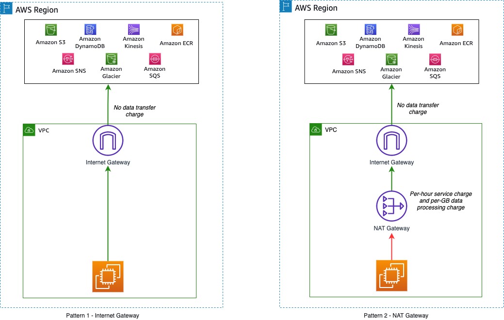
Accessing AWS services in same Region

Figure 1. Accessing AWS services in same Region

Accessing services across AWS Regions

If your workload accesses services in different Regions (Figure 2), there is a charge for data transfer across Regions. The charge depends on the source and destination Region (as described on the Amazon EC2 Data Transfer pricing page).
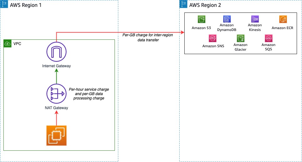
Accessing AWS services in different Region

Figure 2. Accessing AWS services in different Region

Data transfer within different components of your workload

Charges may apply if there is data transfer between different components of your workload. These charges vary depending on where the components are deployed.

Workload components in same AWS Region

Data transfer within the same Availability Zone is free. One way to achieve high availability for a workload is to deploy in multiple Availability Zones.

Consider a workload with two application servers running on Amazon EC2 and a database running on Amazon Relational Database Service (Amazon RDS) for MySQL (Figure 3). For high availability, each application server is deployed into a separate Availability Zone. Here, data transfer charges apply for cross-Availability Zone communication between the EC2 instances. Data transfer charges also apply between Amazon EC2 and Amazon RDS. Consult the Amazon RDS for MySQL pricing guide for more information.

Workload components across Availability Zones

Figure 3. Workload components across Availability Zones

To minimize impact of a database instance failure, enable a multi-Availability Zone configuration within Amazon RDS to deploy a standby instance in a different Availability Zone. Replication between the primary and standby instances does not incur additional data transfer charges. However, data transfer charges will apply from any consumers outside the current primary instance Availability Zone. Refer to the Amazon RDS pricing page for more detail.

A common pattern is to deploy workloads across multiple VPCs in your AWS network. Two approaches to enabling VPC-to-VPC communication are VPC peering connections and AWS Transit Gateway. Data transfer over a VPC peering connection that stays within an Availability Zone is free. Data transfer over a VPC peering connection that crosses Availability Zones will incur a data transfer charge for ingress/egress traffic (Figure 4).

VPC peering connection

Figure 4. VPC peering connection

Transit Gateway can interconnect hundreds or thousands of VPCs (Figure 5). Cost elements for Transit Gateway include an hourly charge for each attached VPC, AWS Direct Connect, or AWS Site-to-Site VPN. Data processing charges apply for each GB sent from a VPC, Direct Connect, or VPN to Transit Gateway.

VPC peering using Transit Gateway in same Region

Figure 5. VPC peering using Transit Gateway in same Region

Workload components in different AWS Regions

If workload components communicate across multiple Regions using VPC peering connections or Transit Gateway, additional data transfer charges apply. If the VPCs are peered across Regions, standard inter-Region data transfer charges will apply (Figure 6).

VPC peering across Regions

Figure 6. VPC peering across Regions

For peered Transit Gateways, you will incur data transfer charges on only one side of the peer. Data transfer charges do not apply for data sent from a peering attachment to a Transit Gateway. The data transfer for this cross-Region peering connection is in addition to the data transfer charges for the other attachments (Figure 7).
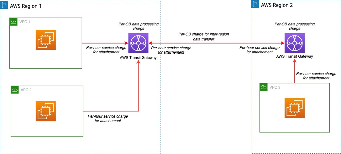
Transit Gateway peering across Regions

Figure 7. Transit Gateway peering across Regions

Data transfer between AWS and on-premises data centers

Data transfer will occur when your workload needs to access resources in your on-premises data center. There are two common options to help achieve this connectivity: Site-to-Site VPN and Direct Connect.

Data transfer over AWS Site-to-Site VPN

One option to connect workloads to an on-premises network is to use one or more Site-to-Site VPN connections (Figure 8 – Pattern 1). These charges include an hourly charge for the connection and a charge for data transferred from AWS. Refer to Site-to-Site VPN pricing for more details. Another option to connect multiple VPCs to an on-premises network is to use a Site-to-Site VPN connection to a Transit Gateway (Figure 8 – Pattern 2). The Site-to-Site VPN will be considered another attachment on the Transit Gateway. Standard Transit Gateway pricing applies.

Site-to-Site VPN patterns

Figure 8. Site-to-Site VPN patterns

Data transfer over AWS Direct Connect

Direct Connect can be used to connect workloads in AWS to on-premises networks. Direct Connect incurs a fee for each hour the connection port is used and data transfer charges for data flowing out of AWS. Data transfer into AWS is $0.00 per GB in all locations. The data transfer charges depend on the source Region and the Direct Connect provider location. Direct Connect can also connect to the Transit Gateway if multiple VPCs need to be connected (Figure 9). Direct Connect is considered another attachment on the Transit Gateway and standard Transit Gateway pricing applies. Refer to the Direct Connect pricing page for more details.
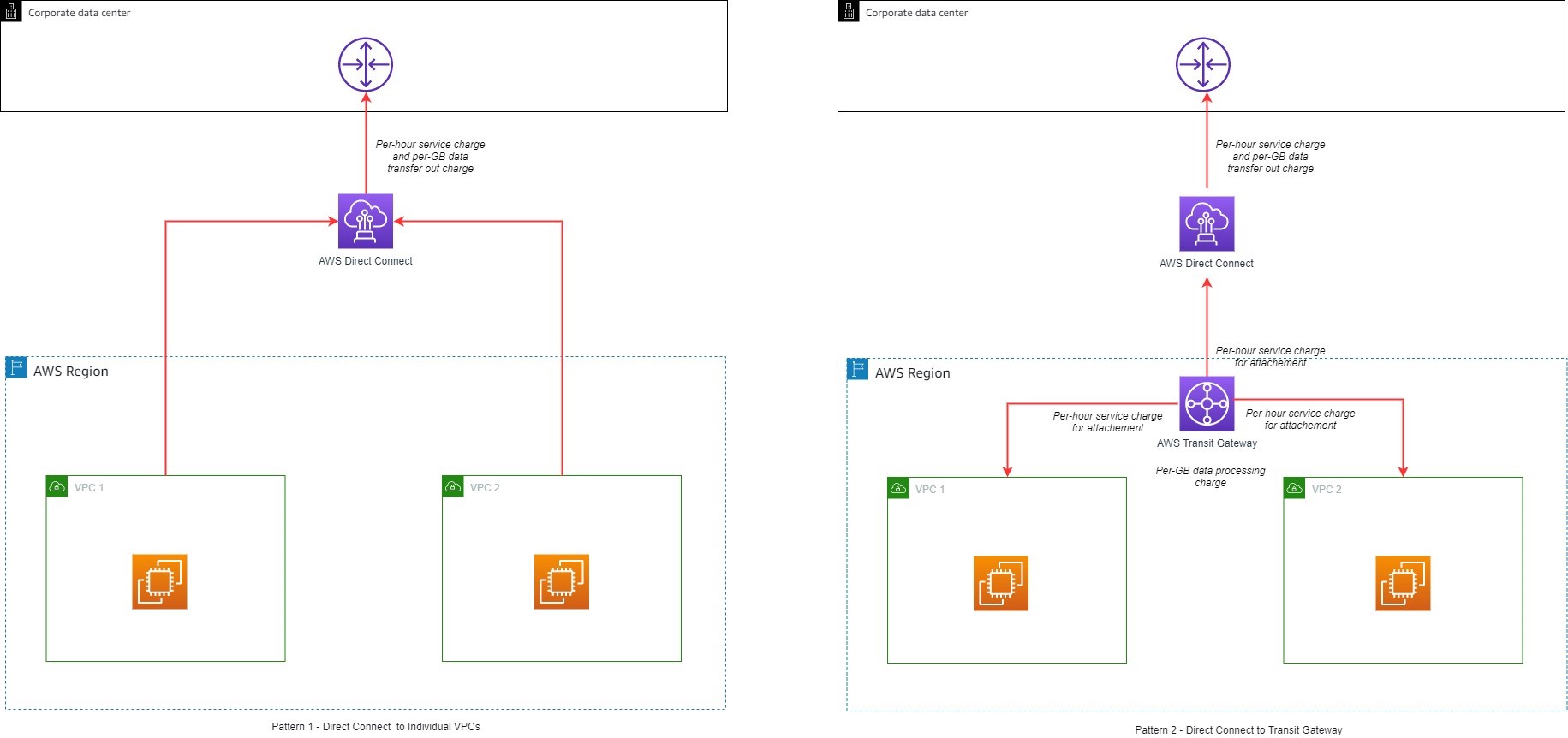
Figure 9. Direct Connect patterns

Figure 9. Direct Connect patterns

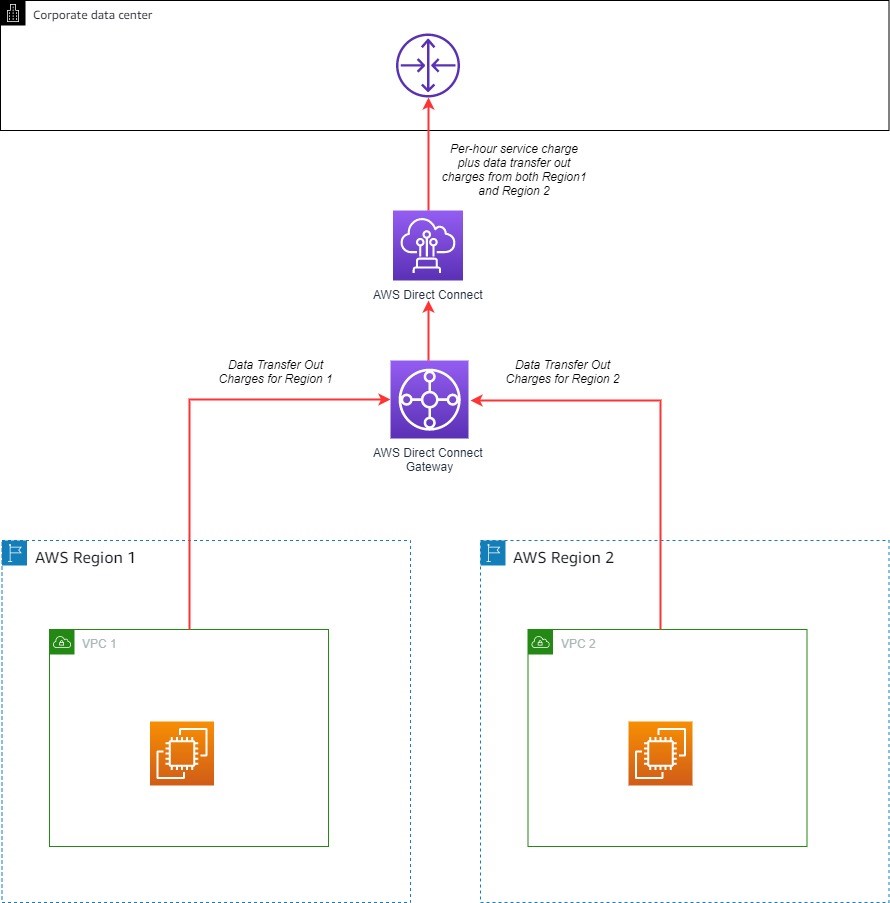
A Direct Connect gateway can be used to share a Direct Connect across multiple Regions. When using a Direct Connect gateway, there will be outbound data charges based on the source Region and Direct Connect location (Figure 10).
Direct Connect gateway

Figure 10. Direct Connect gateway

General tips

Data transfer charges apply based on the source, destination, and amount of traffic. Here are some general tips for when you start planning your architecture:

  • Avoid routing traffic over the internet when connecting to AWS services from within AWS by using VPC endpoints:
    • VPC gateway endpoints allow communication to Amazon S3 and Amazon DynamoDB without incurring data transfer charges.
    • VPC interface endpoints are available for some AWS services. This type of endpoint incurs hourly service charges and data transfer charges.
  • Use Direct Connect instead of the internet for sending data to on-premises networks.
  • Traffic that crosses an Availability Zone boundary typically incurs a data transfer charge. Use resources from the local Availability Zone whenever possible.
  • Traffic that crosses a Regional boundary will typically incur a data transfer charge. Avoid cross-Region data transfer unless your business case requires it.
  • Use the AWS Free Tier. Under certain circumstances, you may be able to test your workload free of charge.
  • Use the AWS Pricing Calculator to help estimate the data transfer costs for your solution.
  • Use a dashboard to better visualize data transfer charges – this workshop will show how.

Conclusion

AWS provides the ability to deploy across multiple Availability Zones and Regions. With a few clicks, you can create a distributed workload. As you increase your footprint across AWS, it helps to understand various data transfer charges that may apply. This blog post provided information to help you make an informed decision and explore different architectural patterns to save on data transfer costs.

Using Route 53 Private Hosted Zones for Cross-account Multi-region Architectures

Post Syndicated from Anandprasanna Gaitonde original https://aws.amazon.com/blogs/architecture/using-route-53-private-hosted-zones-for-cross-account-multi-region-architectures/

This post was co-written by Anandprasanna Gaitonde, AWS Solutions Architect and John Bickle, Senior Technical Account Manager, AWS Enterprise Support

Introduction

Many AWS customers have internal business applications spread over multiple AWS accounts and on-premises to support different business units. In such environments, you may find a consistent view of DNS records and domain names between on-premises and different AWS accounts useful. Route 53 Private Hosted Zones (PHZs) and Resolver endpoints on AWS create an architecture best practice for centralized DNS in hybrid cloud environment. Your business units can use flexibility and autonomy to manage the hosted zones for their applications and support multi-region application environments for disaster recovery (DR) purposes.

This blog presents an architecture that provides a unified view of the DNS while allowing different AWS accounts to manage subdomains. It utilizes PHZs with overlapping namespaces and cross-account multi-region VPC association for PHZs to create an efficient, scalable, and highly available architecture for DNS.

Architecture Overview

You can set up a multi-account environment using services such as AWS Control Tower to host applications and workloads from different business units in separate AWS accounts. However, these applications have to conform to a naming scheme based on organization policies and simpler management of DNS hierarchy. As a best practice, the integration with on-premises DNS is done by configuring Amazon Route 53 Resolver endpoints in a shared networking account. Following is an example of this architecture.

Route 53 PHZs and Resolver Endpoints

Figure 1 – Architecture Diagram

The customer in this example has on-premises applications under the customer.local domain. Applications hosted in AWS use subdomain delegation to aws.customer.local. The example here shows three applications that belong to three different teams, and those environments are located in their separate AWS accounts to allow for autonomy and flexibility. This architecture pattern follows the option of the “Multi-Account Decentralized” model as described in the whitepaper Hybrid Cloud DNS options for Amazon VPC.

This architecture involves three key components:

1. PHZ configuration: PHZ for the subdomain aws.customer.local is created in the shared Networking account. This is to support centralized management of PHZ for ancillary applications where teams don’t want individual control (Item 1a in Figure). However, for the key business applications, each of the teams or business units creates its own PHZ. For example, app1.aws.customer.local – Application1 in Account A, app2.aws.customer.local – Application2 in Account B, app3.aws.customer.local – Application3 in Account C (Items 1b in Figure). Application1 is a critical business application and has stringent DR requirements. A DR environment of this application is also created in us-west-2.

For a consistent view of DNS and efficient DNS query routing between the AWS accounts and on-premises, best practice is to associate all the PHZs to the Networking Account. PHZs created in Account A, B and C are associated with VPC in Networking Account by using cross-account association of Private Hosted Zones with VPCs. This creates overlapping domains from multiple PHZs for the VPCs of the networking account. It also overlaps with the parent sub-domain PHZ (aws.customer.local) in the Networking account. In such cases where there is two or more PHZ with overlapping namespaces, Route 53 resolver routes traffic based on most specific match as described in the Developer Guide.

2. Route 53 Resolver endpoints for on-premises integration (Item 2 in Figure): The networking account is used to set up the integration with on-premises DNS using Route 53 Resolver endpoints as shown in Resolving DNS queries between VPC and your network. Inbound and Outbound Route 53 Resolver endpoints are created in the VPC in us-east-1 to serve as the integration between on-premises DNS and AWS. The DNS traffic between on-premises to AWS requires an AWS Site2Site VPN connection or AWS Direct Connect connection to carry DNS and application traffic. For each Resolver endpoint, two or more IP addresses can be specified to map to different Availability Zones (AZs). This helps create a highly available architecture.

3. Route 53 Resolver rules (Item 3 in Figure): Forwarding rules are created only in the networking account to route DNS queries for on-premises domains (customer.local) to the on-premises DNS server. AWS Resource Access Manager (RAM) is used to share the rules to accounts A, B and C as mentioned in the section “Sharing forwarding rules with other AWS accounts and using shared rules” in the documentation. Account owners can now associate these shared rules with their VPCs the same way that they associate rules created in their own AWS accounts. If you share the rule with another AWS account, you also indirectly share the outbound endpoint that you specify in the rule as described in the section “Considerations when creating inbound and outbound endpoints” in the documentation. This implies that you use one outbound endpoint in a region to forward DNS queries to your on-premises network from multiple VPCs, even if the VPCs were created in different AWS accounts. Resolver starts to forward DNS queries for the domain name that’s specified in the rule to the outbound endpoint and forward to the on-premises DNS servers. The rules are created in both regions in this architecture.

This architecture provides the following benefits:

  1. Resilient and scalable
  2. Uses the VPC+2 endpoint, local caching and Availability Zone (AZ) isolation
  3. Minimal forwarding hops
  4. Lower cost: optimal use of Resolver endpoints and forwarding rules

In order to handle the DR, here are some other considerations:

  • For app1.aws.customer.local, the same PHZ is associated with VPC in us-west-2 region. While VPCs are regional, the PHZ is a global construct. The same PHZ is accessible from VPCs in different regions.
  • Failover routing policy is set up in the PHZ and failover records are created. However, Route 53 health checkers (being outside of the VPC) require a public IP for your applications. As these business applications are internal to the organization, a metric-based health check with Amazon CloudWatch can be configured as mentioned in Configuring failover in a private hosted zone.
  • Resolver endpoints are created in VPC in another region (us-west-2) in the networking account. This allows on-premises servers to failover to these secondary Resolver inbound endpoints in case the region goes down.
  • A second set of forwarding rules is created in the networking account, which uses the outbound endpoint in us-west-2. These are shared with Account A and then associated with VPC in us-west-2.
  • In addition, to have DR across multiple on-premises locations, the on-premises servers should have a secondary backup DNS on-premises as well (not shown in the diagram).
    This ensures a simple DNS architecture for the DR setup, and seamless failover for applications in case of a region failure.

Considerations

  • If Application 1 needs to communicate to Application 2, then the PHZ from Account A must be shared with Account B. DNS queries can then be routed efficiently for those VPCs in different accounts.
  • Create additional IP addresses in a single AZ/subnet for the resolver endpoints, to handle large volumes of DNS traffic.
  • Look at Considerations while using Private Hosted Zones before implementing such architectures in your AWS environment.

Summary

Hybrid cloud environments can utilize the features of Route 53 Private Hosted Zones such as overlapping namespaces and the ability to perform cross-account and multi-region VPC association. This creates a unified DNS view for your application environments. The architecture allows for scalability and high availability for business applications.

Field Notes: Setting Up Disaster Recovery in a Different Seismic Zone Using AWS Outposts

Post Syndicated from Vijay Menon original https://aws.amazon.com/blogs/architecture/field-notes-setting-up-disaster-recovery-in-a-different-seismic-zone-using-aws-outposts/

Recovering your mission-critical workloads from outages is essential for business continuity and providing services to customers with little or no interruption. That’s why many customers replicate their mission-critical workloads in multiple places using a Disaster Recovery (DR) strategy suited for their needs.

With AWS, a customer can achieve this by deploying multi Availability Zone High-Availability setup or a multi-region setup by replicating critical components of an application to another region.  Depending on the RPO and RTO of the mission-critical workload, the requirement for disaster recovery ranges from simple backup and restore, to multi-site, active-active, setup. In this blog post, I explain how AWS Outposts can be used for DR on AWS.

In many geographies, it is possible to set up your disaster recovery for a workload running in one AWS Region to another AWS Region in the same country (for example in US between us-east-1 and us-west-2). For countries where there is only one AWS Region, it’s possible to set up disaster recovery in another country where AWS Region is present. This method can be designed for the continuity, resumption and recovery of critical business processes at an agreed level and limits the impact on people, processes and infrastructure (including IT). Other reasons include to minimize the operational, financial, legal, reputational and other material consequences arising from such events.

However, for mission-critical workloads handling critical user data (PII, PHI or financial data), countries like India and Canada have regulations which mandate to have a disaster recovery setup at a “safe distance” within the same country. This ensures compliance with any data sovereignty or data localization requirements mandated by the regulators. “Safe distance” means the distance between the DR site and the primary site is such that the business can continue to operate in the event of any natural disaster or industrial events affecting the primary site. Depending on the geography, this safe distance could be 50KM or more. These regulations limit the options customers have to use another AWS Region in another country as a disaster recovery site of their primary workload running on AWS.

In this blog post, I describe an architecture using AWS Outposts which helps set up disaster recovery on AWS within the same country at a distance that can meet the requirements set by regulators. This architecture also helps customers to comply with various data sovereignty regulations in a given country. Another advantage of this architecture is the homogeneity of the primary and disaster recovery site. Your existing IT teams can set up and operate the disaster recovery site using familiar AWS tools and technology in a homogenous environment.

Prerequisites

Readers of this blog post should be familiar with basic networking concepts like WAN connectivity, BGP and the following AWS services:

Architecture Overview

I explain the architecture using an example customer scenario in India, where a customer is using AWS Mumbai Region for their mission-critical workload. This workload needs a DR setup to comply with local regulation and the DR setup needs to be in a different seismic zone than the one for Mumbai. Also, because of the nature of the regulated business, the user/sensitive data needs to be stored within India.

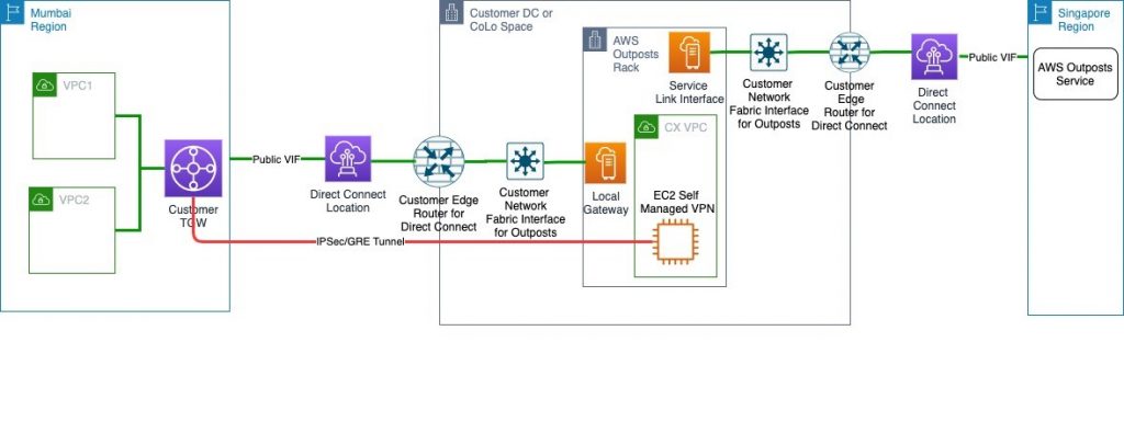
Following is the architecture diagram showing the logical setup.

This solution is similar to a typical AWS Outposts use case where a customer orders the Outposts to be installed in their own Data Centre (DC) or a CoLocation site (Colo). It will follow the shared responsibility model described in AWS Outposts documentation.

The only difference is that the AWS Outpost parent Region will be the closest Region other than AWS Mumbai, in this case Singapore. Customers will then provision an AWS Direct Connect public VIF locally for a Service Link to the Singapore Region. This ensures that the control plane stays available via the AWS Singapore Region even if there is an outage in AWS Mumbai Region affecting control plane availability. You can then launch and manage AWS Outposts supported resources in the AWS Outposts rack.

For data plane traffic, which should not go out of the country, the following options are available:

  • Provision a self-managed Virtual Private Network (VPN) between an EC2 instances running router AMI in a subnet of AWS Outposts and AWS Transit Gateway (TGW) in the primary Region.
  • Provision a self-managed Virtual Private Network (VPN) between an EC2 instances running router AMI in a subnet of AWS Outposts and Virtual Private Gateway (VGW) in the primary Region.

Note: The Primary Region in this example is AWS Mumbai Region. This VPN will be provisioned via Local Gateway and DX public VIF. This ensures that data plane traffic will not traverse any network out of the country (India) to comply with data localization mandated by the regulators.

Architecture Walkthrough

  1. Make sure your data center (DC) or the choice of collocate facility (Colo) meets the requirements for AWS Outposts.
  2. Create an Outpost and order Outpost capacity as described in the documentation. Make sure that you do this step while logged into AWS Outposts console of the AWS Singapore Region.
  3. Provision connectivity between AWS Outposts and network of your DC/Colo as mentioned in AWS Outpost documentation.  This includes setting up VLANs for service links and Local Gateway (LGW).
  4. Provision an AWS Direct Connect connection and public VIF between your DC/Colo and the primary Region via the closest AWS Direct Connect location.
    • For the WAN connectivity between your DC/Colo and AWS Direct Connect location you can choose any telco provider of your choice or work with one of AWS Direct Connect partners.
    • This public VIF will be used to attach AWS Outposts to its parent Region in Singapore over AWS Outposts service link. It will also be used to establish an IPsec GRE tunnel between AWS Outposts subnet and a TGW or VGW for data plane traffic (explained in subsequent steps).
    • Alternatively, you can provision separate Direct Connect connection and public VIFs for Service Link and data plane traffic for better segregation between the two. You will have to provision sufficient bandwidth on Direct Connect connection for the Service Link traffic as well as the Data Plane traffic (like data replication between primary Region and AWS outposts).
    • For an optimal experience and resiliency, AWS recommends that you use dual 1Gbps connections to the AWS Region. This connectivity can also be achieved over Internet transit; however, I recommend using AWS Direct Connect because it provides private connectivity between AWS and your DC/Colo  environment, which in many cases can reduce your network costs, increase bandwidth throughput, and provide a more consistent network experience than Internet-based connections.
  5. Create a subnet in AWS Outposts and launch an EC2 instance running a router AMI of your choice from AWS Marketplace in this subnet. This EC2 instance is used to establish the IPsec GRE tunnel to the TGW or VGW in primary Region.
  6. Add rules in security group of these EC2 instances to allow ISAKMP (UDP 500), NAT Traversal (UDP 4500), and ESP (IP Protocol 50) from VGW or TGW endpoint public IP addresses.
  7. NAT (Network Address Translation) the EIP assigned in step 5 to a public IP address at your edge router connecting to AWS Direct connect or internet transit. This public IP will be used as the customer gateway to establish IPsec GRE tunnel to the primary Region.
  8. Create a customer gateway using the public IP address used to NAT the EC2 instances step 7. Follow the steps in similar process found at Create a Customer Gateway.
  9. Create a VPN attachment for the transit gateway using the customer gateway created in step 8. This VPN must be a dynamic route-based VPN. For steps, review Transit Gateway VPN Attachments. If you are connecting the customer gateway to VPC using VGW in primary Region then follow the steps mentioned at How do I create a secure connection between my office network and Amazon Virtual Private Cloud?.
  10. Configure the customer gateway (EC2 instance running a router AMI in AWS Outposts subnet) side for VPN connectivity. You can base this configuration suggested by AWS during the creation of VPN in step 9. This suggested sample configuration can be downloaded from AWS console post VPN setup as discussed in this document.
  11. Modify the route table of AWS outpost Subnets to point to the EC2 instance launched in step 5 as the target for any destination in your VPCs in the primary Region, which is AWS Mumbai in this example.

At this point, you will have end-to-end connectivity between VPCs in a primary Region and resources in an AWS Outposts. This connectivity can now be used to replicate data from your primary site to AWS Outposts for DR purposes. This  keeps the setup compliant with any internal or external data localization requirements.

Conclusion

In this blog post, I described an architecture using AWS Outposts for Disaster Recovery on AWS in countries without a second AWS Region. To set up disaster recovery, your existing IT teams can set up and operate the disaster recovery site using the familiar AWS tools and technology in a homogeneous environment. To learn more about AWS Outposts, refer to the documentation and FAQ.

Field Notes provides hands-on technical guidance from AWS Solutions Architects, consultants, and technical account managers, based on their experiences in the field solving real-world business problems for customers.

New Whitepaper: Selecting & Designing Your Hybrid Connectivity Model

Post Syndicated from Santiago Freitas original https://aws.amazon.com/blogs/architecture/new-whitepaper-selecting-designing-your-hybrid-connectivity-model/

Introduction

Many organizations need to connect their on-premises data centers, remote sites, and the cloud. A hybrid network connects these different environments.

A modern organization uses an extensive array of IT resources. In the past, it was common to host these resources in an on-premises data center or a colocation facility. With the increased adoption of cloud computing, IT resources are delivered and consumed from cloud service providers over a network connection. In some cases, organizations have opted to migrate all existing IT resources to the cloud. In other cases, organizations maintain IT resources both on premises and in the cloud. In both cases, a common network is required to connect on-premises and cloud resources. Coexistence of on-premises and cloud resources is called “hybrid cloud” and the common network connecting them is referred to as a “hybrid network. “ Even if your organization keeps all of its IT resources in the cloud, it may still require hybrid connectivity to remote sites.

There are several connectivity models to choose from. Although having options adds flexibility, selecting the best option requires analysis of the business and technical requirements and the elimination of options that are not suitable. Requirements can be grouped together across considerations, such as: security, time to deploy, performance, reliability, communication model, scalability, and more. Once requirements are carefully collected, analyzed, and considered, network and cloud architects identify applicable AWS hybrid network building blocks and solutions. To identify and select the optimal model(s), architects must understand advantages and disadvantages of each model. There are also technical limitations that might cause an otherwise good model to be excluded.

Consideration covered in the whitepaper

Figure 1 – Consideration covered on the whitepaper.

A new whitepaper on Hybrid Connectivity describes AWS building blocks and the key things to consider when deciding which hybrid connectivity model is right for you. To help you determine the best solution for your business and technical requirements, we provide decision trees to guide you through the logical selection process as well as a customer use case to show how to apply the considerations and decision trees in practice.

Decision tree applied to Example Corp. Automotive use case

Figure 2: Example Corp. Automotive connection type decision tree

Contributors

Contributors to this new whitepaper on Hybrid Connectivity are: Marwan Al Shawi, AWS Solutions Architect; Santiago Freitas, AWS Head of Technology; Evgeny Vaganov, AWS Specialist Solutions Architect – Networking; and Tom Adamski, AWS Specialist Solutions Architect – Networking. Special thanks to Stephen Bird, AWS Senior Program Manager – Content.