Post Syndicated from Aravind Gopaluni original https://aws.amazon.com/blogs/security/encryption-in-transit-over-external-networks-aws-guidance-for-nydfs-and-beyond/
On November 1, 2023, the New York State Department of Financial Services (NYDFS) issued its Second Amendment (the Amendment) to its Cybersecurity Requirements for Financial Services Companies adopted in 2017, published within Section 500 of 23 NYCRR 500 (the Cybersecurity Requirements; the Cybersecurity Requirements as amended by the Amendment, the Amended Cybersecurity Requirements). In the introduction to its Cybersecurity Resource Center, the Department explains that the revisions are aimed at addressing the changes in the increasing sophistication of threat actors, the prevalence of and relative ease in running cyberattacks, and the availability of additional controls to manage cyber risks.
This blog post focuses on the revision to the encryption in transit requirement under section 500.15(a). It outlines the encryption capabilities and secure connectivity options offered by Amazon Web Services (AWS) to help customers demonstrate compliance with this updated requirement. The post also provides best practices guidance, emphasizing the shared responsibility model. This enables organizations to design robust data protection strategies that address not only the updated NYDFS encryption requirements but potentially also other security standards and regulatory requirements.
The target audience for this information includes security leaders, architects, engineers, and security operations team members and risk, compliance, and audit professionals.
Note that the information provided here is for informational purposes only; it is not legal or compliance advice and should not be relied on as legal or compliance advice. Customers are responsible for making their own independent assessments and should obtain appropriate advice from their own legal and compliance advisors regarding compliance with applicable NYDFS regulations.
500.15 Encryption of nonpublic information
The updated requirement in the Amendment states that:
- As part of its cybersecurity program, each covered entity shall implement a written policy requiring encryption that meets industry standards, to protect nonpublic information held or transmitted by the covered entity both in transit over external networks and at rest.
- To the extent a covered entity determines that encryption of nonpublic information at rest is infeasible, the covered entity may instead secure such nonpublic information using effective alternative compensating controls that have been reviewed and approved by the covered entity’s CISO in writing. The feasibility of encryption and effectiveness of the compensating controls shall be reviewed by the CISO at least annually.
This section of the Amendment removes the covered entity’s chief information security officer’s (CISO) discretion to approve compensating controls when encryption of nonpublic information in transit over external networks is deemed infeasible. The Amendment mandates that, effective November 2024, organizations must encrypt nonpublic information transmitted over external networks without the option of implementing alternative compensating controls. While the use of security best practices such as network segmentation, multi-factor authentication (MFA), and intrusion detection and prevention systems (IDS/IPS) can provide defense in depth, these compensating controls are no longer sufficient to replace encryption in transit over external networks for nonpublic information.
However, the Amendment still allows for the CISO to approve the use of alternative compensating controls where encryption of nonpublic information at rest is deemed infeasible. AWS is committed to providing industry-standard encryption services and capabilities to help protect customer data at rest in the cloud, offering customers the ability to add layers of security to their data at rest, providing scalable and efficient encryption features. This includes the following services:
- Data encryption capabilities available in AWS storage and database services, such as Amazon Elastic Block Store (Amazon EBS), Amazon Simple Storage Service (Amazon S3), Amazon Relational Database Service (Amazon RDS), and Amazon Redshift.
- Flexible key management options, including AWS Key Management Service (AWS KMS), which allow you to choose whether to have AWS manage the encryption keys or keep complete control over your keys.
- Dedicated, hardware-based cryptographic key storage using AWS CloudHSM, to help you adhere to compliance requirements
While the above highlights encryption-at-rest capabilities offered by AWS, the focus of this blog post is to provide guidance and best practice recommendations for encryption in transit.
AWS guidance and best practice recommendations
Cloud network traffic encompasses connections to and from the cloud and traffic between cloud service provider (CSP) services. From an organization’s perspective, CSP networks and data centers are deemed external because they aren’t under the organization’s direct control. The connection between the organization and a CSP, typically established over the internet or dedicated links, is considered an external network. Encrypting data in transit over these external networks is crucial and should be an integral part of an organization’s cybersecurity program.
AWS implements multiple mechanisms to help ensure the confidentiality and integrity of customer data during transit and at rest across various points within its environment. While AWS employs transparent encryption at various transit points, we strongly recommend incorporating encryption by design into your architecture. AWS provides robust encryption-in-transit capabilities to help you adhere to compliance requirements and mitigate the risks of unauthorized disclosure and modification of nonpublic information in transit over external networks.
Additionally, AWS recommends that financial services institutions adopt a secure by design (SbD) approach to implement architectures that are pre-tested from a security perspective. SbD helps establish control objectives, security baselines, security configurations, and audit capabilities for workloads running on AWS.
Security and Compliance is a shared responsibility between AWS and the customer. Shared responsibility can vary depending on the security configuration options for each service. You should carefully consider the services you choose because your organization’s responsibilities vary depending on the services used, the integration of those services into your IT environment, and applicable laws and regulations. AWS provides resources such as service user guides and AWS Customer Compliance Guides, which map security best practices for individual services to leading compliance frameworks, including NYDFS.
Protecting connections to and from AWS
We understand that customers place a high priority on privacy and data security. That’s why AWS gives you ownership and control over your data through services that allow you to determine where your content will be stored, secure your content in transit and at rest, and manage access to AWS services and resources for your users. When architecting workloads on AWS, classifying data based on its sensitivity, criticality, and compliance requirements is essential. Proper data classification allows you to implement appropriate security controls and data protection mechanisms, such as Transport Layer Security (TLS) at the application layer, access control measures, and secure network connectivity options for nonpublic information over external networks. When it comes to transmitting nonpublic information over external networks, it’s a recommended practice to identify network segments traversed by this data based on your network architecture. While AWS employs transparent encryption at various transit points, it’s advisable to implement encryption solutions at multiple layers of the OSI model to establish defense in depth and enhance end-to-end encryption capabilities. Although requirement 500.15 of the Amendment doesn’t mandate end-to-end encryption, implementing such controls can provide an added layer of security and can help demonstrate that nonpublic information is consistently encrypted during transit.
AWS offers several options to achieve this. While not every option provides end-to-end encryption on its own, using them in combination helps to ensure that nonpublic information doesn’t traverse open, public networks unprotected. These options include:
- Using AWS Direct Connect with IEEE 802.1AE MAC Security Standard (MACsec) encryption
- VPN connections
- Secure API endpoints
- Client-side encryption of data before sending it to AWS
AWS Direct Connect with MACsec encryption
AWS Direct Connect provides direct connectivity to the AWS network through third-party colocation facilities, using a cross-connect between an AWS owned device and either a customer- or partner-owned device. Direct Connect can reduce network costs, increase bandwidth throughput, and provide a more consistent network experience than internet-based connections. Within Direct Connect connections (a physical construct) there will be one or more virtual interfaces (VIFs). These are logical entities and are reflected as industry-standard 802.1Q VLANs on the customer equipment terminating the Direct Connect connection. Depending on the type of VIF, they will use either public or private IP addressing. There are three different types of VIFs:
- Public virtual interface – Establish connectivity between AWS public endpoints and your data center, office, or colocation environment.
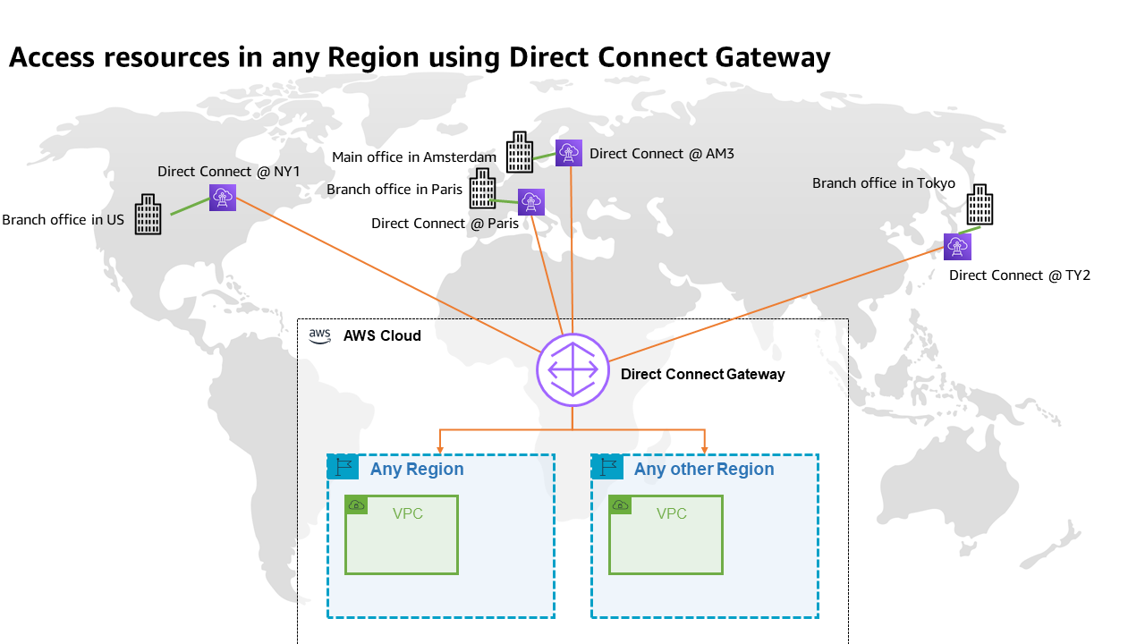
- Transit virtual interface – Establish private connectivity between AWS Transit Gateways and your data center, office, or colocation environment. Transit Gateways is an AWS managed high availability and scalability regional network transit hub used to interconnect Amazon Virtual Private Cloud (Amazon VPC) and customer networks.
- Private virtual interface – Establish private connectivity between Amazon VPC resources and your data center, office, or colocation environment.
By default, a Direct Connect connection isn’t encrypted from your premises to the Direct Connect location because AWS cannot assume your on-premises device supports the MACsec protocol. With MACsec, Direct Connect delivers native, near line-rate, point-to-point encryption, ensuring that data communications between AWS and your corporate network remain protected. MACsec is supported on 10 Gbps and 100 Gbps dedicated Direct Connect connections at selected points of presence. Using Direct Connect with MACsec-enabled connections and combining it with the transparent physical network encryption offered by AWS from the Direct Connect location through the AWS backbone not only benefits you by allowing you to securely exchange data with AWS, but also enables you to use the highest available bandwidth. For additional information on MACsec support and cipher suites, see the MACsec section in the Direct Connect FAQs.
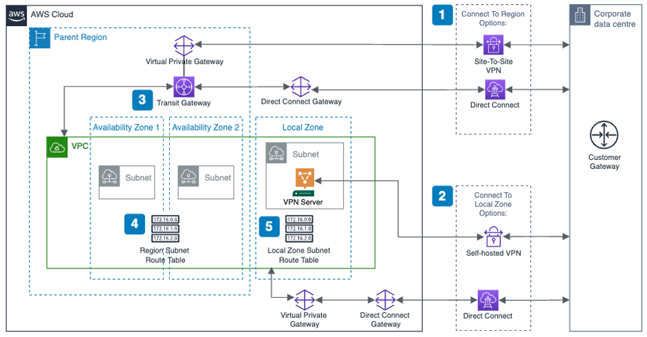
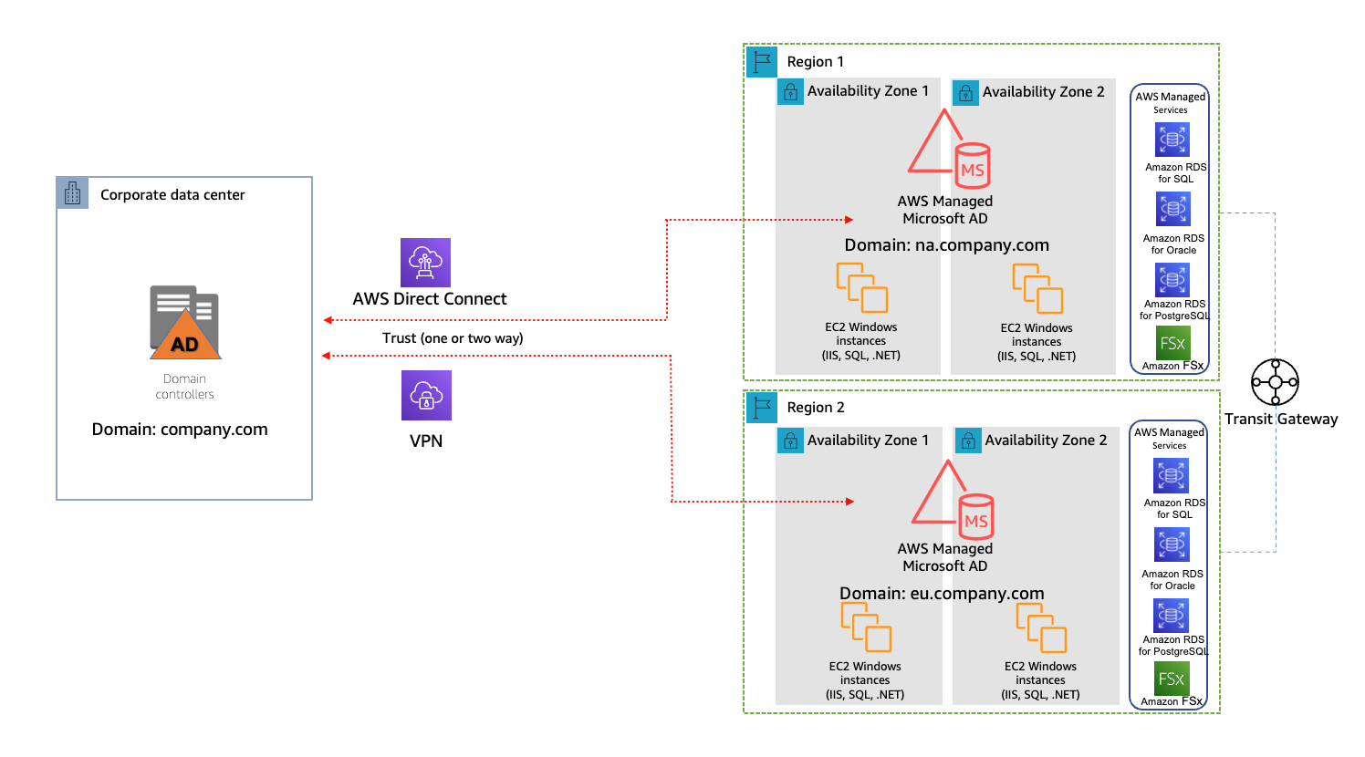
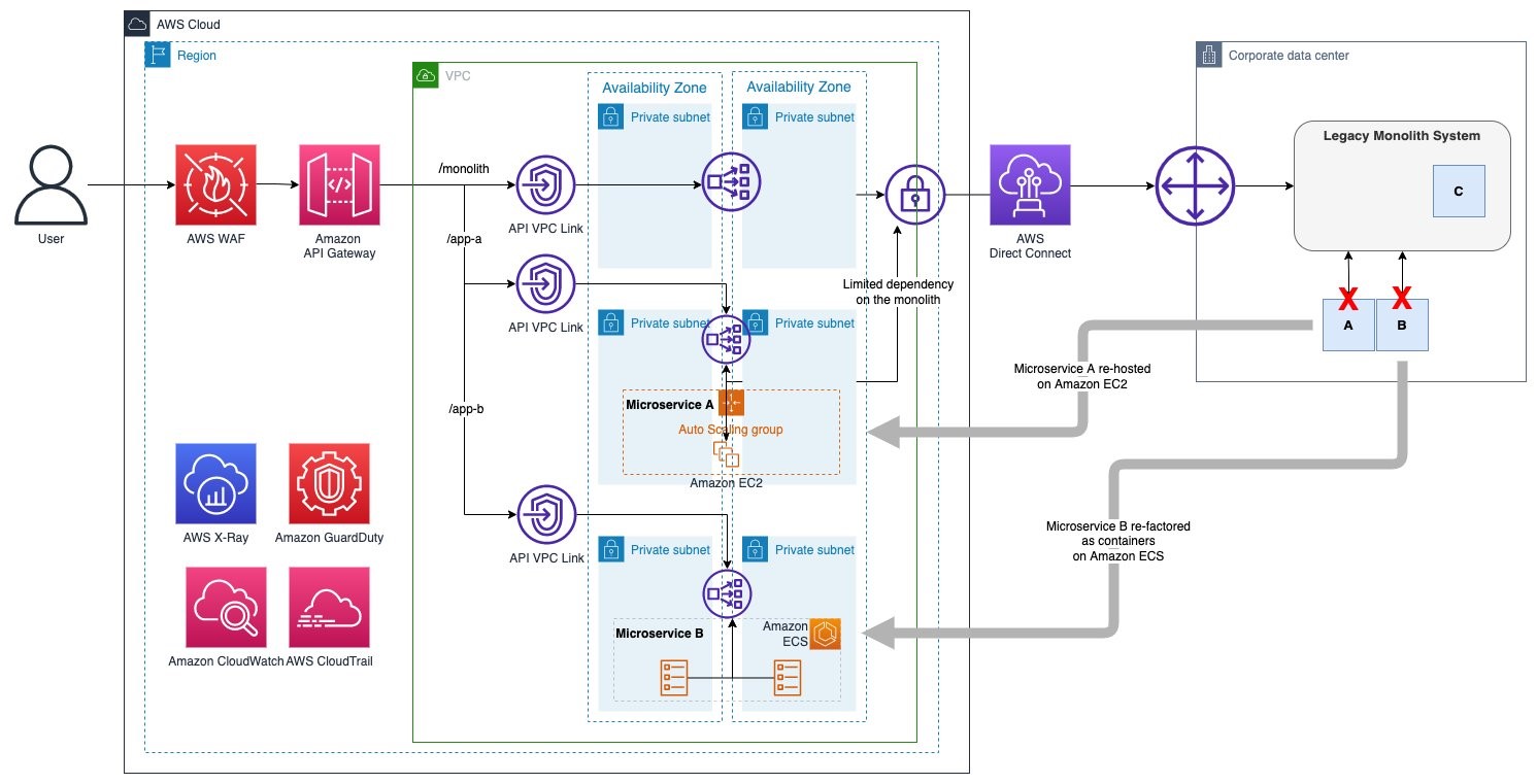
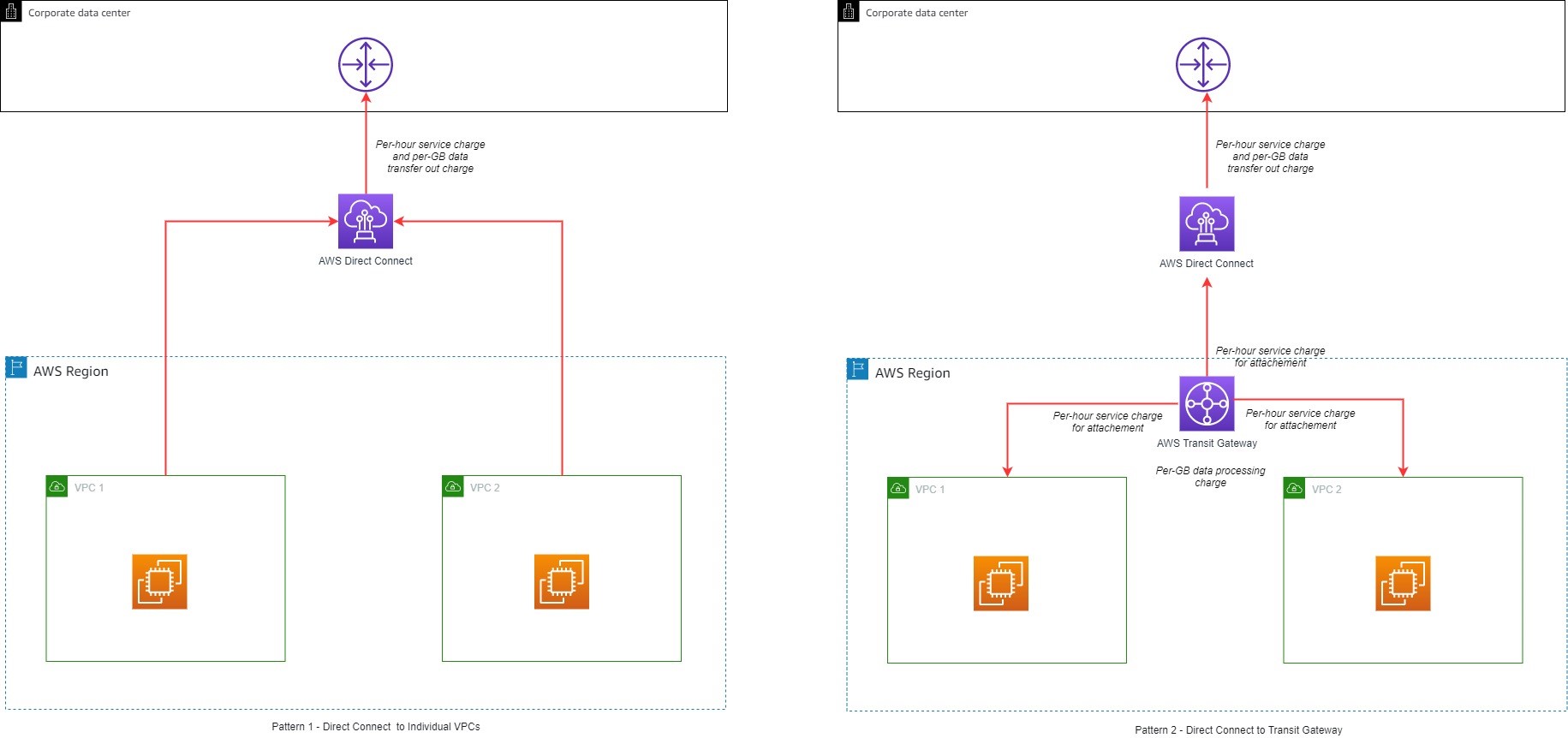
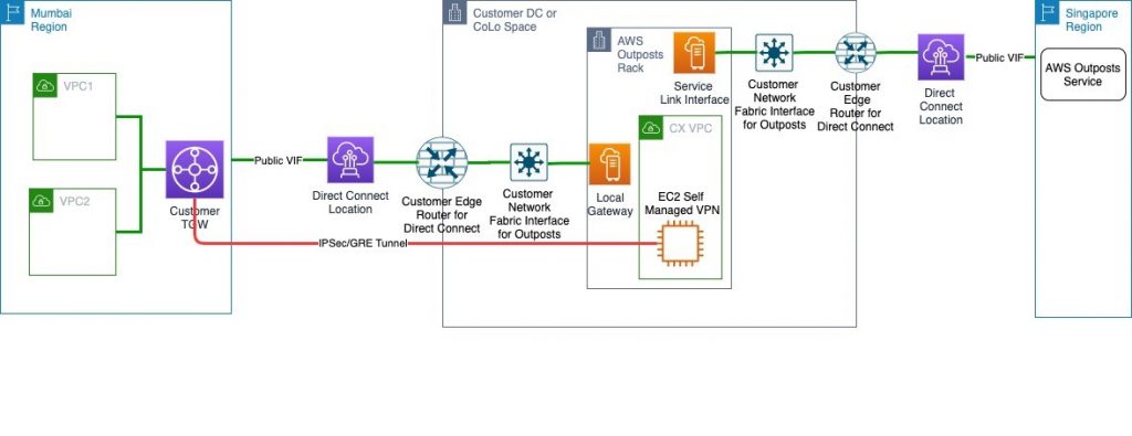
Figure 1 illustrates a sample reference architecture for securing traffic from corporate network to your VPCs over Direct Connect with MACsec and AWS Transit Gateways.

Figure 1: Sample architecture for using Direct Connect with MACsec encryption
In the sample architecture, you can see that Layer 2 encryption through MACsec only encrypts the traffic from your on-premises systems to the AWS device in the Direct Connect location, and therefore you need to consider additional encryption solutions at Layer 3, 4, or 7 to get closer to end-to-end encryption to the device where you’re comfortable for the packets to be decrypted. In the next section, let’s review an option for using network layer encryption using AWS Site-to-Site VPN.
Direct Connect with Site-to-Site VPN
AWS Site-to-Site VPN is a fully managed service that creates a secure connection between your corporate network and your Amazon VPC using IP security (IPsec) tunnels over the internet. Data transferred between your VPC and the remote network routes over an encrypted VPN connection to help maintain the confidentiality and integrity of data in transit. Each VPN connection consists of two tunnels between a virtual private gateway or transit gateway on the AWS side and a customer gateway on the on-premises side. Each tunnel supports a maximum throughput of up to 1.25 Gbps. See Site-to-Site VPN quotas for more information.
You can use Site-to-Site VPN over Direct Connect to achieve secure IPsec connection with the low latency and consistent network experience of Direct Connect when reaching resources in your Amazon VPCs.
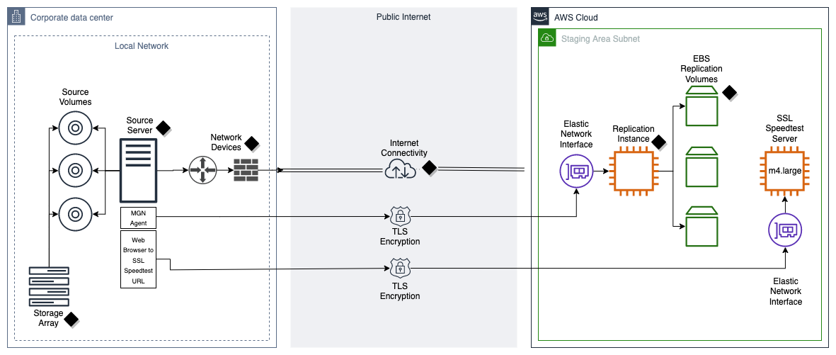
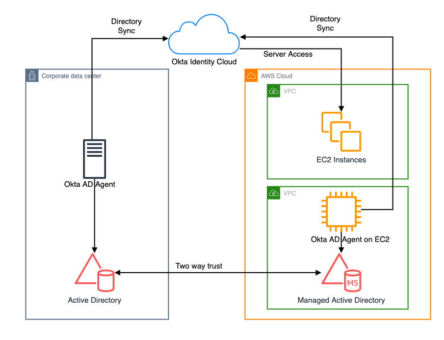
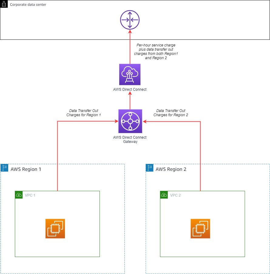
Figure 2 illustrates a sample reference architecture for establishing end-to-end IPsec-encrypted connections between your networks and Transit Gateway over a private dedicated connection.

Figure 2: Encrypted connections between the AWS Cloud and a customer’s network using VPN
While Direct Connect with MACsec and Site-to-Site VPN with IPsec can provide encryption at the physical and network layers respectively, they primarily secure the data in transit between your on-premises network and the AWS network boundary. To further enhance the coverage for end-to-end encryption, it is advisable to use TLS encryption. In the next section, let’s review mechanisms for securing API endpoints on AWS using TLS encryption.
Secure API endpoints
APIs act as the front door for applications to access data, business logic, or functionality from other applications and backend services.
AWS enables you to establish secure, encrypted connections to its services using public AWS service API endpoints. Public AWS owned service API endpoints (AWS managed services like Amazon Simple Queue Service (Amazon SQS), AWS Identity and Access Management (IAM), AWS Key Management Service (AWS KMS), others) have certificates that are owned and deployed by AWS. By default, requests to these public endpoints use HTTPS. To align with evolving technology and regulatory standards for TLS, as of February 27, 2024, AWS has updated its TLS policy to require a minimum of TLS 1.2, thereby deprecating support for TLS 1.0 and 1.1 versions on AWS service API endpoints across each of our AWS Regions and Availability Zones.
Additionally, to enhance connection performance, AWS has begun enabling TLS version 1.3 globally for its service API endpoints. If you’re using the AWS SDKs or AWS Command Line Interface (AWS CLI), you will automatically benefit from TLS 1.3 after a service enables it.
While requests to public AWS service API endpoints use HTTPS by default, a few services, such as Amazon S3 and Amazon DynamoDB, allow using either HTTP or HTTPS. If the client or application chooses HTTP, the communication isn’t encrypted. Customers are responsible for enforcing HTTPS connections when using such AWS services. To help ensure secure communication, you can establish an identity perimeter by using the IAM policy condition key aws:SecureTransport in your IAM roles to evaluate the connection and mandate HTTPS usage.
As enterprises increasingly adopt cloud computing and microservices architectures, teams frequently build and manage internal applications exposed as private API endpoints. Customers are responsible for managing the certificates on private customer-owned endpoints. AWS helps you deploy private customer-owned identities (that is, TLS certificates) through the use of AWS Certificate Manager (ACM) private certificate authorities (PCA) and the integration with AWS services that offer private customer-owned TLS termination endpoints.
ACM is a fully managed service that lets you provision, manage, and deploy public and private TLS certificates for use with AWS services and internal connected resources. ACM minimizes the time-consuming manual process of purchasing, uploading, and renewing TLS certificates. You can provide certificates for your integrated AWS services either by issuing them directly using ACM or by importing third-party certificates into the ACM management system. ACM offers two options for deploying managed X.509 certificates. You can choose the best one for your needs.
- AWS Certificate Manager (ACM) – This service is for enterprise customers who need a secure web presence using TLS. ACM certificates are deployed through Elastic Load Balancing (ELB), Amazon CloudFront, Amazon API Gateway, and other integrated AWS services. The most common application of this type is a secure public website with significant traffic requirements. ACM also helps to simplify security management by automating the renewal of expiring certificates.
- AWS Private Certificate Authority (Private CA) – This service is for enterprise customers building a public key infrastructure (PKI) inside the AWS Cloud and is intended for private use within an organization. With AWS Private CA, you can create your own certificate authority (CA) hierarchy and issue certificates with it for authenticating users, computers, applications, services, servers, and other devices. Certificates issued by a private CA cannot be used on the internet. For more information, see the AWS Private CA User Guide.
You can use a centralized API gateway service, such as Amazon API Gateway, to securely expose customer-owned private API endpoints. API Gateway is a fully managed service that allows developers to create, publish, maintain, monitor, and secure APIs at scale. With API Gateway, you can create RESTful APIs and WebSocket APIs, enabling near real-time, two-way communication applications. API Gateway operations must be encrypted in-transit using TLS, and require the use of HTTPS endpoints. You can use API Gateway to configure custom domains for your APIs using TLS certificates provisioned and managed by ACM. Developers can optionally choose a specific TLS version for their custom domain names. For use cases that require mutual TLS (mTLS) authentication, you can configure certificate-based mTLS authentication on your custom domains.
Pre-encryption of data to be sent to AWS
Depending on the risk profile and sensitivity of the data that’s being transferred to AWS, you might want to choose encrypting data in an application running on your corporate network before sending it to AWS (client-side encryption). AWS offers a variety of SDKs and client-side encryption libraries to help you encrypt and decrypt data in your applications. You can use these libraries with the cryptographic service provider of your choice, including AWS Key Management Service or AWS CloudHSM, but the libraries do not require an AWS service.
- The AWS Encryption SDK is a client-side encryption library that you can use to encrypt and decrypt data in your application and is available in several programming languages, including a command-line interface. You can use the SDK to encrypt your data before you send it to an AWS service. The SDK offers advanced data protection features, including envelope encryption and additional authenticated data (AAD). It also offers secure, authenticated, symmetric key algorithm suites, such as 256-bit AES-GCM with key derivation and signing.
- The AWS Database Encryption SDK is a set of software libraries developed in open source that enable you to include client-side encryption in your database design. The SDK provides record-level encryption solutions. You specify which fields are encrypted and which fields are included in the signatures that help ensure the authenticity of your data. Encrypting your sensitive data in transit and at rest helps ensure that your plaintext data isn’t available to a third party, including AWS. The AWS Database Encryption SDK for DynamoDB is designed especially for DynamoDB applications. It encrypts the attribute values in each table item using a unique encryption key. It then signs the item to protect it against unauthorized changes, such as adding or deleting attributes or swapping encrypted values. After you create and configure the required components, the SDK transparently encrypts and signs your table items when you add them to a table. It also verifies and decrypts them when you retrieve them. Searchable encryption in the AWS Database Encryption SDK enables you search encrypted records without decrypting the entire database. This is accomplished by using beacons, which create a map between the plaintext value written to a field and the encrypted value that is stored in your database. For more information, see the AWS Database Encryption SDK Developer Guide.
- The Amazon S3 Encryption Client is a client-side encryption library that enables you to encrypt an object locally to help ensure its security before passing it to Amazon S3. It integrates seamlessly with the Amazon S3 APIs to provide a straightforward solution for client-side encryption of data before uploading to Amazon S3. After you instantiate the Amazon S3 Encryption Client, your objects are automatically encrypted and decrypted as part of your Amazon S3 PutObject and GetObject requests. Your objects are encrypted with a unique data key. You can use both the Amazon S3 Encryption Client and server-side encryption to encrypt your data. The Amazon S3 Encryption Client is supported in a variety of programming languages and supports industry-standard algorithms for encrypting objects and data keys. For more information, see the Amazon S3 Encryption Client developer guide.
Encryption in-transit inside AWS
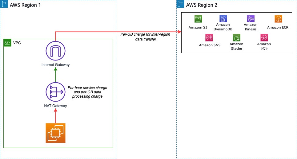
AWS implements responsible and sophisticated technical and physical controls that are designed to help prevent unauthorized access to or disclosure of your content. To protect data in transit, traffic traversing through the AWS network that is outside of AWS physical control is transparently encrypted by AWS at the physical layer. This includes traffic between AWS Regions (except China Regions), traffic between Availability Zones, and between Direct Connect locations and Regions through the AWS backbone network.
Network segmentation
When you create an AWS account, AWS offers a virtual networking option to launch resources in a logically isolated virtual private network (VPN), Amazon Virtual Private Cloud (Amazon VPC). A VPC is limited to a single AWS Region and every VPC has one or more subnets. VPCs can be connected externally using an internet gateway (IGW), VPC peering connection, VPN, Direct Connect, or Transit Gateways. Traffic within the your VPC is considered internal because you have complete control over your virtual networking environment, including selection of your own IP address range, creation of subnets, and configuration of route tables and network gateways.
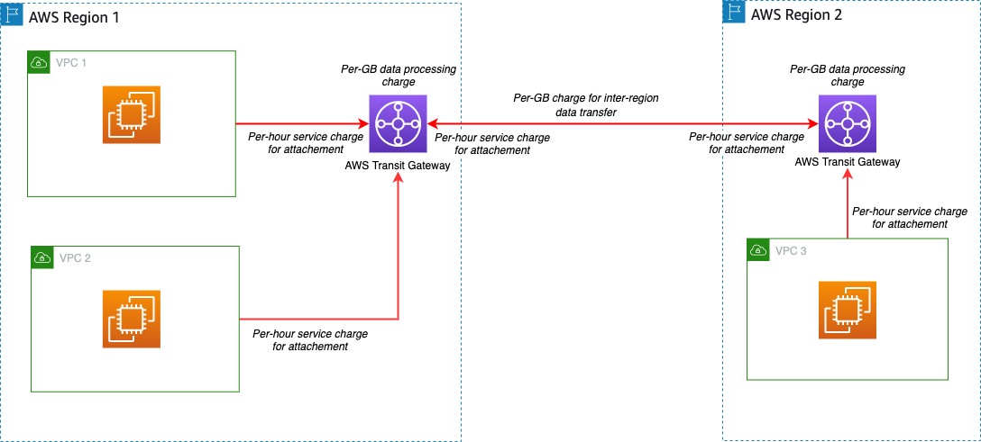
As a customer, you maintain ownership of your data, and you select which AWS services can process, store, and host your data, and you choose the Regions in which your data is stored. AWS doesn’t automatically replicate data across Regions, unless the you choose to do so. Data transmitted over the AWS global network between Regions and Availability Zones is automatically encrypted at the physical layer before leaving AWS secured facilities. Cross-Region traffic that uses Amazon VPC and Transit Gateway peering is automatically bulk-encrypted when it exits a Region.
Encryption between instances
AWS provides secure and private connectivity between Amazon Elastic Compute Cloud (Amazon EC2) instances of all types. The Nitro System is the underlying foundation for modern Amazon EC2 instances. It’s a combination of purpose-built server designs, data processors, system management components, and specialized firmware that provides the underlying foundation for EC2 instances launched since the beginning of 2018. Instance types that use the offload capabilities of the underlying Nitro System hardware automatically encrypt in-transit traffic between instances. This encryption uses Authenticated Encryption with Associated Data (AEAD) algorithms, with 256-bit encryption and has no impact on network performance. To support this additional in-transit traffic encryption between instances, instances must be of supported instance types, in the same Region, and in the same VPC or peered VPCs. For a list of supported instance types and additional requirements, see Encryption in transit.
Conclusion
The second Amendment to the NYDFS Cybersecurity Regulation underscores the criticality of safeguarding nonpublic information during transmission over external networks. By mandating encryption for data in transit and eliminating the option for compensating controls, the Amendment reinforces the need for robust, industry-standard encryption measures to protect the confidentiality and integrity of sensitive information.
AWS provides a comprehensive suite of encryption services and secure connectivity options that enable you to design and implement robust data protection strategies. The transparent encryption mechanisms that AWS has built into services across its global network infrastructure, secure API endpoints with TLS encryption, and services such as Direct Connect with MACsec encryption and Site-to-Site VPN, can help you establish secure, encrypted pathways for transmitting nonpublic information over external networks.
By embracing the principles outlined in this blog post, financial services organizations can address not only the updated NYDFS encryption requirements for section 500.15(a) but can also potentially demonstrate their commitment to data security across other security standards and regulatory requirements.
For further reading on considerations for AWS customers regarding adherence to the Second Amendment to the NYDFS Cybersecurity Regulation, see the AWS Compliance Guide to NYDFS Cybersecurity Regulation.
If you have feedback about this post, submit comments in the Comments section below. If you have questions about this post, start a new thread on the AWS Financial Services re:Post and AWS Security, Identity, & Compliance re:Post ,or contact AWS Support.
 This migration approach uses the following tools to perform the migration: