Tag Archives: CloudEndure Disaster Recovery

Automated in-AWS Failback for AWS Elastic Disaster Recovery

Post Syndicated from Steve Roberts original https://aws.amazon.com/blogs/aws/automated-in-aws-failback-for-aws-elastic-disaster-recovery/

I first covered AWS Elastic Disaster Recovery (DRS) in a 2021 blog post. In that post, I described how DRS “enables customers to use AWS as an elastic recovery site for their on-premises applications without needing to invest in on-premises DR infrastructure that lies idle until needed. Once enabled, DRS maintains a constant replication posture for your operating systems, applications, and databases.” I’m happy to announce that, today, DRS now also supports in-AWS failback, adding to the existing support for non-disruptive recovery drills and on-premises failback included in the original release.

I also wrote in my earlier post that drills are an important part of disaster recovery since, if you don’t test, you simply won’t know for sure that your disaster recovery solution will work properly when you need it to. However, customers rarely like to test because it’s a time-consuming activity and also disruptive. Automation and simplification encourage frequent drills, even at scale, enabling you to be better prepared for disaster, and now you can use them irrespective of whether your applications are on-premises or in AWS. Non-disruptive recovery drills provide confidence that you will meet your recovery time objectives (RTOs) and recovery point objectives (RPOs) should you ever need to initiate a recovery or failback. More information on RTOs and RPOs, and why they’re important to define, can be found in the recovery objectives documentation.

The new automated support provides a simplified and expedited experience to fail back Amazon Elastic Compute Cloud (Amazon EC2) instances to the original Region, and both failover and failback processes (for on-premises or in-AWS recovery) can be conveniently started from the AWS Management Console. Also, for customers that want to customize the granular steps that make up a recovery workflow, DRS provides three new APIs, linked at the bottom of this post.

Failover vs. Failback
Failover is switching the running application to another Availability Zone, or even a different Region, should outages or issues occur that threaten the availability of the application. Failback is the process of returning the application to the original on-premises location or Region. For failovers to another Availability Zone, customers who are agnostic to the zone may continue running the application in its new zone indefinitely if so required. In this case, they will reverse the recovery replication, so the recovered instance is protected for future recovery. However, if the failover was to a different Region, its likely customers will want to eventually fail back and return to the original Region when the issues that caused failover have been resolved.

The below images illustrate architectures for in-AWS applications protected by DRS. The architecture in the image below is for cross-Availability Zone scenarios.

Cross-Availability Zone architecture for DRS

The architecture diagram below is for cross-Region scenarios.

Cross-Region architecture for DRS

Let’s assume an incident occurs with an in-AWS application, so we initiate a failover to another AWS Region. When the issue has been resolved, we want to fail back to the original Region. The following animation illustrates the failover and failback processes.

Illustration of the failover and failback processes

Learn more about in-AWS failback with Elastic Disaster Recovery
As I mentioned earlier, three new APIs are also available for customers who want to customize the granular steps involved. The documentation for these can be found using the links below.

The new in-AWS failback support is available in all Regions where AWS Elastic Disaster Recovery is available. Learn more about AWS Elastic Disaster Recovery in the User Guide. For specific information on the new failback support I recommend consulting this topic in the service User Guide

— Steve

Scalable, Cost-Effective Disaster Recovery in the Cloud

Post Syndicated from Steve Roberts original https://aws.amazon.com/blogs/aws/scalable-cost-effective-disaster-recovery-in-the-cloud/

Should disaster strike, business continuity can require more than just periodic data backups. A full recovery that meets the business’s recovery time objectives (RTOs) must also include the infrastructure, operating systems, applications, and configurations used to process their data. The growing threats of ransomware highlight the need to be able to perform a full point-in-time recovery. For businesses affected by a ransomware attack, restoration of data from an old, possibly manual, backup will not be sufficient.

Previously, businesses have elected to provision separate, physical disaster recovery (DR) infrastructure. However, customers tell us this can be both space- and cost-prohibitive, involving capital expenditure on hardware and facilities that remain idle until called upon. The infrastructure also incurs overhead in terms of regular inspection and maintenance, typically manual, to ensure that should it ever be called upon, it’s ready and able to handle the current business load, which may have grown considerably since initial provisioning. This also makes testing difficult and expensive.

Today, I am happy to announce AWS Elastic Disaster Recovery (DRS) a fully scalable, cost-effective disaster recovery service for physical, virtual, and cloud servers, based on CloudEndure Disaster Recovery. DRS enables customers to use AWS as an elastic recovery site without needing to invest in on-premises DR infrastructure that lies idle until needed. Once enabled, DRS maintains a constant replication posture for your operating systems, applications, and databases. This helps businesses meet recovery point objectives (RPOs) of seconds, and RTOs of minutes, after disaster strikes. In cases of ransomware attacks, for example, DRS also allows recovery to a previous point in time.

DRS provides for recovery that scales as needed to match your current setup and does not need any time-consuming manual processes to maintain that readiness. It also offers the ability to perform disaster recovery readiness drills. Just as it’s important to test restoration of data from backups, being able to conduct recovery drills in a cost-effective manner without impacting ongoing replication or user activities can help give confidence that you can meet your objectives and customer expectations should you need to call on a recovery.

AWS Elastic Disaster Recovery console home

Elastic Disaster Recovery in Action
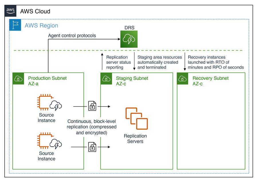
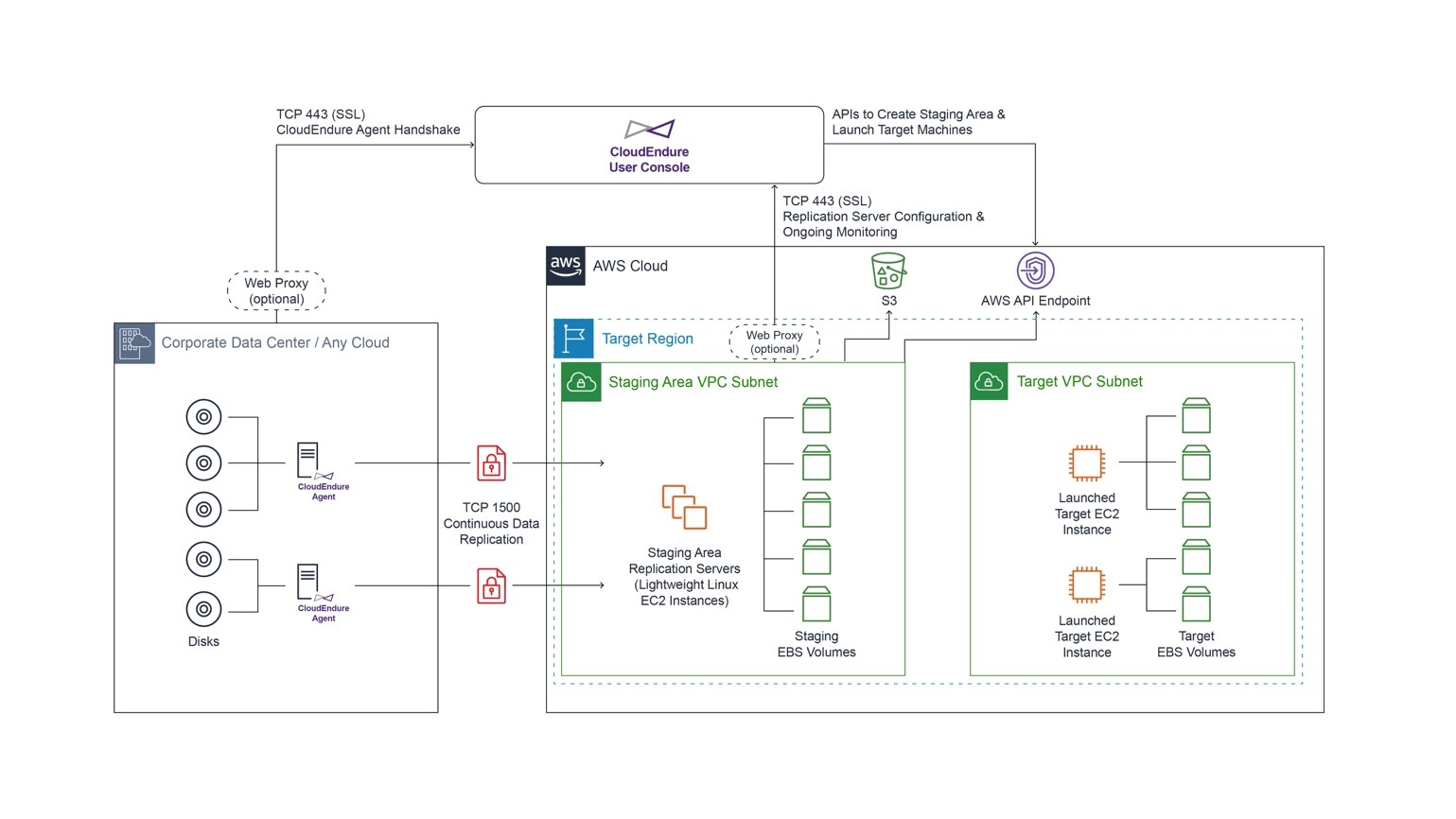
Once enabled, DRS continuously replicates block storage volumes from physical, virtual, or cloud-based servers, allowing it to support business RPOs measured in seconds. Recovery includes applications running on physical infrastructure, VMware vSphere, Microsoft Hyper-V, and cloud infrastructure to AWS. You’re able to recover all your applications and databases that run on supported Windows and Linux operating systems, with DRS orchestrating the recovery process for your servers on AWS to support an RTO measured in minutes.

Using an agent that you install on your servers, DRS securely replicates the data to a staging area subnet in a selected Region in your AWS account. The staging area subnet reduces costs to you, using affordable storage and minimal compute resources. Within the DRS console, you can recover Amazon Elastic Compute Cloud (Amazon EC2) instances in a different AWS Region if required. With DRS automating replication and recovery procedures, you can set up, test, and operate your disaster recovery capability using a single process without the need for specialized skill sets.

DRS gives you the flexibility to pay on an hourly basis, instead of needing to commit to a long-term contract or a set number of servers, a benefit over on-premises or data center recovery solutions. DRS charges hourly, on a pay-as-you-go basis. You can find specific details on pricing at the product page.

Exploring Elastic Disaster Recovery
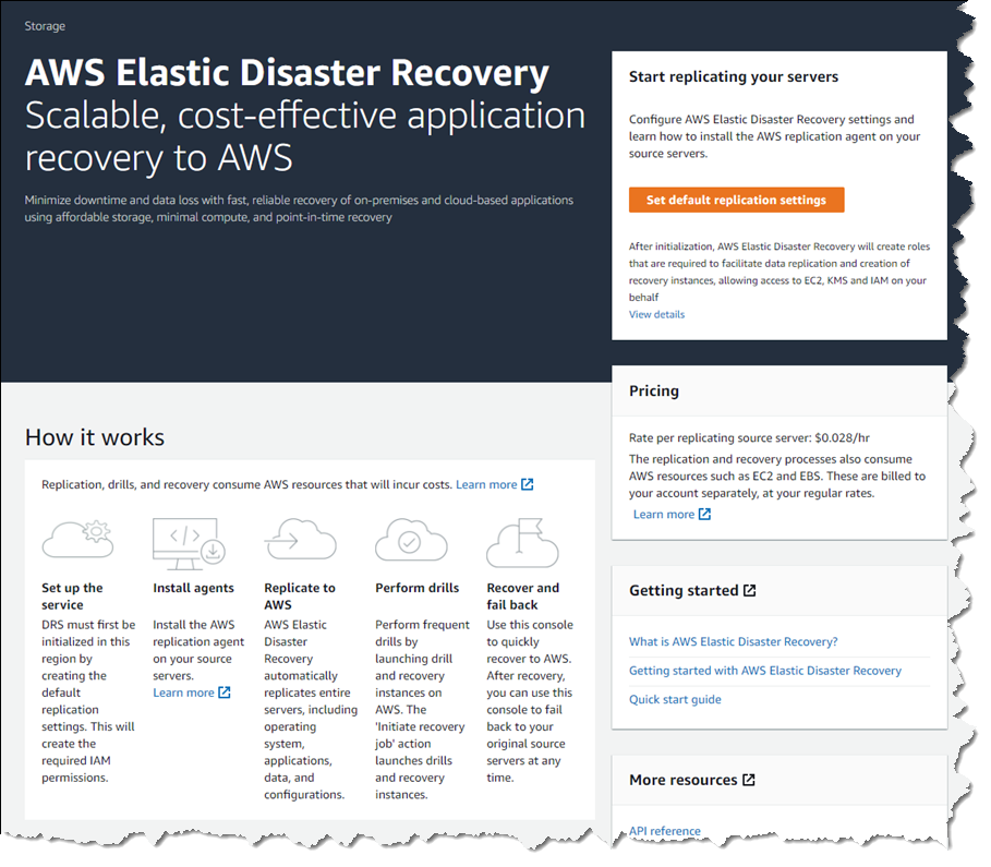
To set up disaster recovery for my resources I first need to configure my default replication settings. As I mentioned earlier, DRS can be used with physical, virtual, and cloud servers. For this post, I’m going to use a collection of EC2 instances as my source servers for disaster recovery.

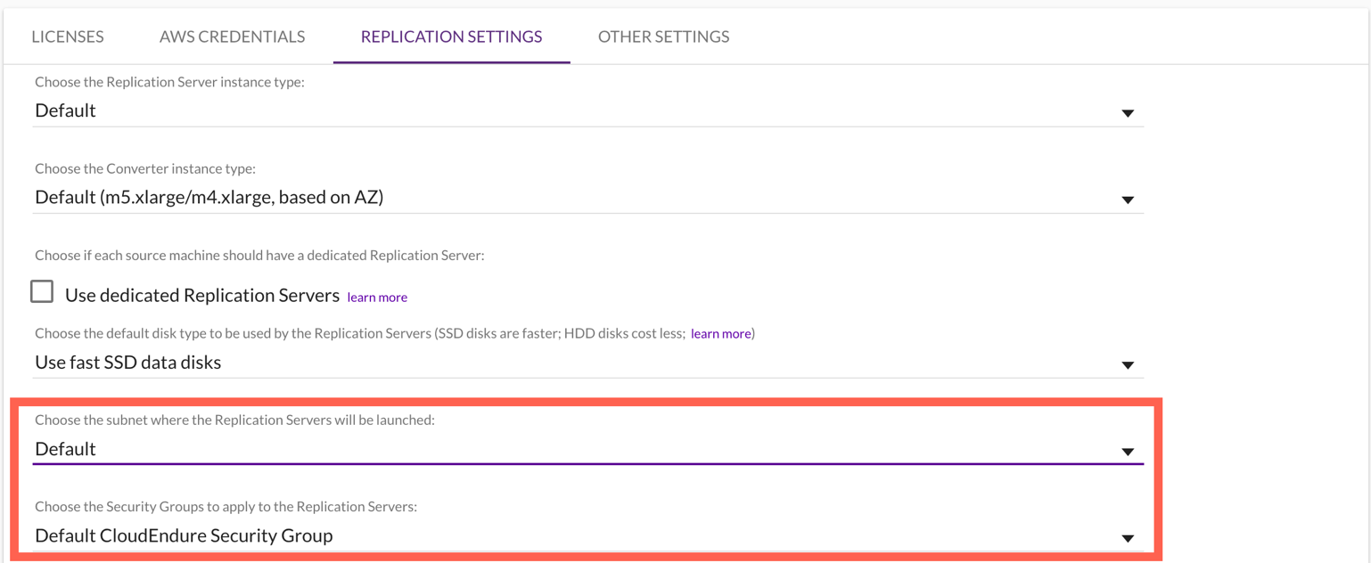
From the DRS console home, shown earlier, choosing Set default replication settings takes me to a short initialization wizard. In the wizard, I first need to select an Amazon Virtual Private Cloud (VPC) subnet that will be used for staging. This subnet does not need to be in the same VPC as my resources, but I need to select one that is not private or blocked to the world. Below, I’ve chosen a subnet from my default VPC in my Region. I can also change the instance type used for the replication instance. I chose to keep the suggested default and clicked Next to proceed.

Choosing the staging area subnet and replication instance type for DRS

I also left the default settings unchanged for the next two pages. In Volumes and security groups, the wizard suggests I use the general-purpose SSD (gp3) Amazon Elastic Block Store (EBS) storage type and to use a security group provided by DRS. On the Additional settings page I can elect to use a private IP for data replication instead of routing over the public internet, and set the snapshot retention period, which defaults to seven days. Clicking Next one final time, I arrive at the Review and create page of the wizard. Choosing Create default completes the process of configuring my default replication settings.

Finalizing default replication settings for DRS

With my replication settings finalized (I can edit them later if I wish, from the Actions menu on the Source servers console page) it’s time to set up my servers. I’m running a test fleet in EC2 that includes two Windows Server 2019 instances, and three Amazon Linux 2 instances. The DRS User Guide contains full instructions on how to obtain and set up the agent on each server type, so I won’t repeat them here. As I run and configure the agent on each of my server instances, the Source servers list automatically updates to include the new source server. The status of the initial sync, and future replication and recovery status of each source server, are summarized in this view.

Replication sync activity on servers

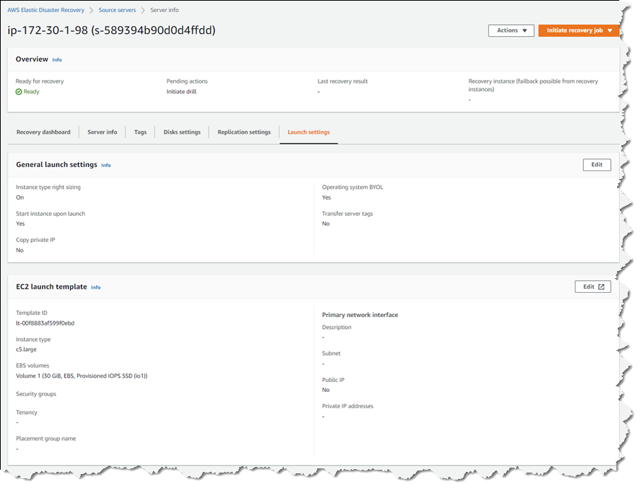
Selecting a hostname entry in the list takes me to a detail page. Here I can view a recovery dashboard, information on the underlying server, disk settings (including the ability to change the staging disk type from the default gp3 type selected by the initialization wizard, or whatever you choose during setup), and launch settings, shown below, that govern the recovery instance that will be created if I choose to initiate a drill or an actual recovery job.

DRS launch settings for a recovery server

Just like data backups, where established best practice is to periodically verify that the backups can actually be used to restore data, we recommend a similar best practice for disaster recovery. So, with my servers all configured and fully replicated, I decided to start a drill for a point-in-time (PIT) recovery for two of my servers. On these instances, following initial replication, I’d installed some additional software. In my scenario, perhaps this installation had gone badly wrong, or I’d fallen victim to a ransomware attack. Either way, I wanted to know and be confident that I could recover my servers if and when needed.

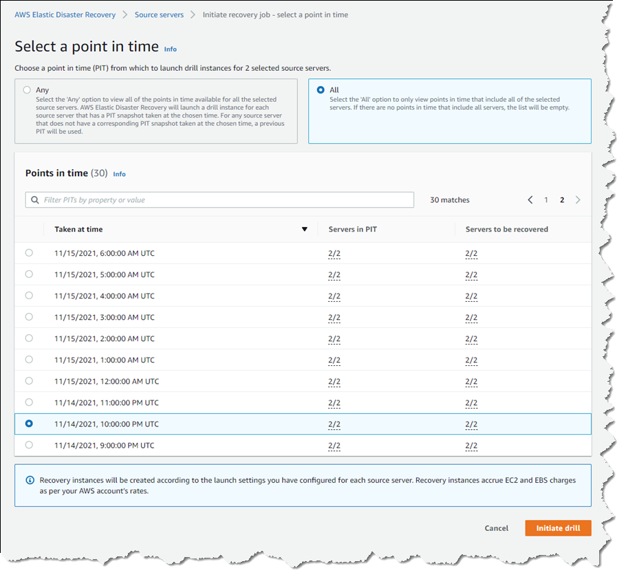
In the Source servers list I selected the two servers that I’d modified and from the Initiate recovery job drop-down menu, chose Initiate drill. Next, I can choose the recovery PIT I’m interested in. This view defaults to Any, meaning it lists all recovery PIT snapshots for the servers I selected. Or, I can choose to filter to All, meaning only PIT snapshots that apply to all the selected servers will be listed. Selecting All, I chose a time just after I’d completed installing additional software on the instances, and clicked Initiate drill.

Selecting a recovery point-in-time for multiple servers

I’m returned to the Source servers list, which shows status as the recovery proceeds. However, I switched to the Recovery job history view for more detail.

In-progress recovery drill

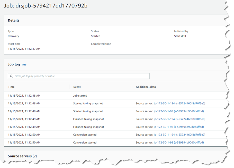
Clicking the job ID, I can drill down further to view a detail page of the source servers involved in the recovery (and can drill down further for each), as well as an overall recovery job log.

Viewing the recovery job log

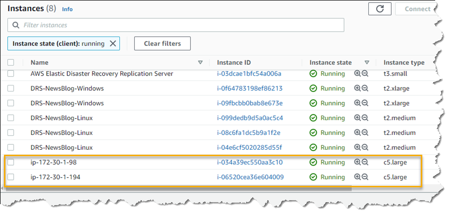
Note – during a drill, or an actual recovery, if you go to the EC2 console you’ll notice one or more additional instances, started by DRS, running in your account (in addition to the replication server). These temporary instances, named AWS Elastic Disaster Recovery Conversion Server, are used to process the PIT snapshots onto the actual recovery instance(s) and will be terminated when the job is complete.

Once the recovery is complete, I can see two new instances in my EC2 environment. These are in the state matching the point-in-time recovery I selected, and are using the instance types I selected earlier in the DRS initialization wizard. I can now connect to them to verify that the recovery drill performed as expected before terminating them. Had this been a real recovery, I would have the option of terminating the original instances to replace them with the recovery versions, or handle whatever other tasks are needed to complete the disaster recovery for my business.

New instances matching my point-in-time recovery selection

Set Up Your Disaster Recovery Environment Today
AWS Elastic Disaster Recovery is generally available now in the US East (N. Virginia), US East (Ohio), US West (Oregon), Asia Pacific (Singapore), Asia Pacific (Sydney), Asia Pacific (Tokyo), Europe (Frankfurt), Europe (Ireland), and Europe (London) Regions. Review the AWS Elastic Disaster Recovery User Guide for more details on setup and operation, and get started today with DRS to eliminate idle recovery site resources, enjoy pay-as-you-go billing, and simplify your deployments to improve your disaster recovery objectives.

— Steve

Field Notes: How Sportradar Accelerated Data Recovery Using AWS Services

Post Syndicated from Mithil Prasad original https://aws.amazon.com/blogs/architecture/field-notes-how-sportradar-accelerated-data-recovery-using-aws-services/

This post was co-written by Mithil Prasad, AWS Senior Customer Solutions Manager, Patrick Gryczkat, AWS Solutions Architect, Ben Burdsall, CTO at Sportradar and Justin Shreve, Director of Engineering at Sportradar. 

Ransomware is a type of malware which encrypts data, effectively locking those affected by it out of their own data and requesting a payment to decrypt the data.  The frequency of ransomware attacks has increased over the past year, with local governments, hospitals, and private companies experiencing cases of ransomware.

For Sportradar, providing their customers with access to high quality sports data and insights is central to their business. Ensuring that their systems are designed securely and in a way which minimizes the possibility of a ransomware attack is top priority.  While ransomware attacks can occur both on premises and in the cloud, AWS services offer increased visibility and native encryption and back up capabilities. This helps prevent and minimize the likelihood and impact of a ransomware attack.

Recovery, backup, and the ability to go back to a known good state is best practice. To further expand their defense and diminish the value of ransom, the Sportradar architecture team set out to leverage their AWS Step Functions expertise to minimize recovery time. The team’s strategy centered on achieving a short deployment process. This process commoditized their production environment, allowing them to spin up interchangeable environments in new isolated AWS accounts, pulling in data from external and isolated sources, and diminishing the value of a production environment as a ransom target. This also minimized the impact of a potential data destruction event.

By partnering with AWS, Sportradar was able to build a secure and resilient infrastructure to provide timely recovery of their service in the event of data destruction by an unauthorized third party. Sportradar automated the deployment of their application to a new AWS account and established a new isolation boundary from an account with compromised resources. In this blog post, we show how the Sportradar architecture team used a combination of AWS CodePipeline and AWS Step Functions to automate and reduce their deployment time to less than two hours.

Solution Overview

Sportradar’s solution uses AWS Step Functions to orchestrate the deployment of resources, the recovery of data, and the deployment of application code, and to navigate all necessary dependencies for order of deployment. While deployment can be orchestrated through CodePipeline, Sportradar used their familiarity with Step Functions to create a quick and repeatable deployment process for their environment.

Sportradar’s solution to a ransomware Disaster Recovery scenario has also provided them with a reliable and accelerated process for deploying development and testing environments. Developers are now able to scale testing and development environments up and down as needed.  This has allowed their Development and QA teams to follow the pace of feature development, versus weekly or bi-weekly feature release and testing schedules tied to a single testing environment.

Reference Architecture Showing How Sportradar Accelerated Data Recovery

Figure 1 – Reference Architecture Diagram showing Automated Deployment Flow

Prerequisites

The prerequisites for implementing this deployment strategy are:

  • An implemented database backup policy
  • Ideally data should be backed up to a data bunker AWS account outside the scope of the environment you are looking to protect. This is so that in the event of a ransomware attack, your backed up data is isolated from your affected environment and account
  • Application code within a GitHub repository
  • Separation of duties
  • Access and responsibility for the backups and GitHub repository should be separated to different stakeholders in order to reduce the likelihood of both being impacted by a security breach

Step 1: New Account Setup 

Once data destruction is identified, the first step in Sportradar’s process is to use a pre-created runbook to create a new AWS account.  A new account is created in case the malicious actors who have encrypted the application’s data have access to not just the application, but also to the AWS account the application resides in.

The runbook sets up a VPC for a selected Region, as well as spinning up the following resources:

  • Security Groups with network connectivity to their git repository (in this case GitLab), IAM Roles for their resources
  • KMS Keys
  • Amazon S3 buckets with CloudFormation deployment templates
  • CodeBuild, CodeDeploy, and CodePipeline

Step 2: Deploying Secrets

It is a security best practice to ensure that no secrets are hard coded into your application code. So, after account setup is complete, the new AWS accounts Access Keys and the selected AWS Region are passed into CodePipeline variables. The application secrets are then deployed to the AWS Parameter Store.

Step 3: Deploying Orchestrator Step Function and In-Memory Databases

To optimize deployment time, Sportradar decided to leave the deployment of their in-memory databases running on Amazon EC2 outside of their orchestrator Step Function.  They deployed the database using a CloudFormation template from their CodePipeline. This was in parallel with the deployment of the Step Function, which orchestrates the rest of their deployment.

Step 4: Step Function Orchestrates the Deployment of Microservices and Alarms

The AWS Step Functions orchestrate the deployment of Sportradar’s microservices solutions, deploying 10+ Amazon RDS instances, and restoring each dataset from DB snapshots. Following that, 80+ producer Amazon SQS queues and  S3 buckets for data staging were deployed. After the successful deployment of the SQS queues, the Lambda functions for data ingestion and 15+ data processing Step Functions are deployed to begin pulling in data from various sources into the solution.

Then the API Gateways and Lambda functions which provide the API layer for each of the microservices are deployed in front of the restored RDS instances. Finally, 300+ Amazon CloudWatch Alarms are created to monitor the environment and trigger necessary alerts. In total Sportradar’s deployment process brings online: 15+ Step Functions for data processing, 30+ micro-services, 10+ Amazon RDS instances with over 150GB of data, 80+ SQS Queues, 180+ Lambda functions, CDN for UI, Amazon Elasticache, and 300+ CloudWatch alarms to monitor the applications. In all, that is over 600 resources deployed with data restored consistently in less than 2 hours total.

Reference Architecture Diagram for How Sportradar Accelerated Data Recovery Using AWS Services

Figure 2 – Reference Architecture Diagram of the Recovered Application

Conclusion

In this blog, we showed how Sportradar’s team used Step Functions to accelerate their deployments, and a walk-through of an example disaster recovery scenario. Step Functions can be used to orchestrate the deployment and configuration of a new environment, allowing complex environments to be deployed in stages, and for those stages to appropriately wait on their dependencies.

For examples of Step Functions being used in different orchestration scenarios, check out how Step Functions acts as an orchestrator for ETLs in Orchestrate multiple ETL jobs using AWS Step Functions and AWS Lambda and Orchestrate Apache Spark applications using AWS Step Functions and Apache Livy. For migrations of Amazon EC2 based workloads, read more about CloudEndure, Migrating workloads across AWS Regions with CloudEndure Migration.

Field Notes provides hands-on technical guidance from AWS Solutions Architects, consultants, and technical account managers, based on their experiences in the field solving real-world business problems for customers.


Ben Burdsall

Ben Burdsall

Ben is currently the chief technology officer of Sportradar, – a data provider to the sporting industry, where he leads a product and engineering team of more than 800. Before that, Ben was part of the global leadership team of Worldpay.

Justin Shreve

Justin Shreve

Justin is Director of Engineering at Sportradar, leading an international team to build an innovative enterprise sports analytics platform.

Field Notes: Protecting Domain-Joined Workloads with CloudEndure Disaster Recovery

Post Syndicated from Daniel Covey original https://aws.amazon.com/blogs/architecture/field-notes-protecting-domain-joined-workloads-with-cloudendure-disaster-recovery/

Co-authored by Daniel Covey, Solutions Architect, at CloudEndure, an AWS Company and Luis Molina, Senior Cloud Architect at AWS. 

When designing a Disaster Recovery plan, one of the main questions we are asked is how Microsoft Active Directory will be handled during a test or failover scenario. In this blog, we go through some of the options for IT professionals who are using the CloudEndure Disaster Recovery (DR) tool, and how to best architect it in certain scenarios.

Overview of architecture

In the following architecture, we show how you can protect domain-joined workloads in the case of a disaster. You can instruct CloudEndure Disaster Recovery to automatically launch thousands of your machines in their fully provisioned state in minutes.

CloudEndure DR Architecture diagram

Scenario 1: Full Replication Failover

Walkthrough

In this scenario, we are performing a full stack Region to Region recovery including Microsoft Active Directory services.

Using CloudEndure Disaster Recovery  to protect Active Directory in Amazon EC2.

This will be a lift-and-shift style implementation. You take the on-premises Active Directory, and failover to another Region. Although not shown in this blog, this can be done from either on-premises, Cross-Region, or Cross-Cloud during DR or Testing.

Prerequisites

For this walkthrough, you should have the following:

  • An AWS account
  • A CloudEndure Account
  • A CloudEndure project configured, with agents installed and replicating in ‘Continuous Data Replication’ Mode
  • A CloudEndure Recovery Plan configured to boot the Active Directory Domain controller first, followed by remaining servers
  • An understanding of Active Directory
  • Two separate VPCs, with matching CIDR ranges, and no connection to the source infrastructure.

Configuration and Launch of Recovery Plan

1. Log in to the CloudEndure Console
2. Ensure the blueprint settings for each machine are configured to boot either in the Test VPC or Failover VPC, depending on the reason for booting,
a. These changes can be done either through the console, or by using the CloudEndure API operations.
b. To change blueprints on a mass scale, use the mass blueprint setter scripts (Zip file with instructions).
3. Open “Recovery Plans” section for the project
a. Create a new Recovery Plan following these steps
b. Tip: Add in a delay between the launch of the Active Directory server, and the following servers, to allow Active Directory services to come up before the rest of the infrastructure.
4. Once you have created the Recovery Plan, you can either launch it from the CloudEndure console, or use the CloudEndure API Operations.

*Note: there is full CloudEndure failover and failback documentation.

There are different ways to clean up resources, depending on whether this was a test launch, or true failover.

  • Test Launch – You can choose the “Delete x target machines” under the “Machines” tab.
    • This will delete all machines created by CloudEndure in the VPC they were launched into.
  • True failover – At this time, you can choose to failback as needed.
    • Once failback is completed, you can use the same preceding steps as to delete the infrastructure spun up by CloudEndure.

Scenario 2: Warm Site Recovery

Walkthrough

In this scenario, we perform a failover/recovery into a Region with a fully writeable and online Active Directory domain controller. This domain controller is running as an EC2 instance and is an extension of the on-premises, or cross cloud/region Active Directory infrastructure.

Prerequisites

For this walkthrough, you should have the following:

  • An AWS account
  • A CloudEndure Account
  • A CloudEndure project configured, with agents installed and replicating in Continuous Data Replication Mode
  • An understanding of Active Directory
  • A deployment of Active Directory with online writeable domain controller(s)

Preparing AWS and Active Directory:

For our example us-west-1 (California) will be the  source environment CloudEndure is protecting. We have specified us-east-1 (N.Virginia) as the target recovery Region aka “warm site”.

  • The source Region will consist of a VPC configured with public and private (AD domain) subnets and security groups
  • AD Domain Controllers are deployed in the source environment (DC1 and DC2)

Procedure:

1.     Set up a target recovery site/VPC in a Region of your choice. We refer to this as the warm site.

2.     Configure connectivity between the source environment you are protecting, and the warm site.

a.     This can be accomplished in multiple ways depending on whether your source environment is on-premises (VPN or Direct connect), an alternate cloud provider (VPN tunnel), or a different AWS Region (VPC peering). For our example the source environment we are protecting is in us-west-1, and the warm recovery site is in us-east-1, both regions VPCs are connected via VPC peering.

3.     Establish connectivity between the source environment and the warm site. This ensures that the appropriate routes, subnets and ACLs are configured to allow AD authentication and replication traffic to flow between the source and warm recovery site.

4.     Extend your Active Directory into the warm recovery site by deploying a domain controller (DC3) into the warm site. This domain controller will handle Active Directory authentication and DNS for machines that get recovered into the warm site.

5.     Next, create a new Active Directory site. Use the Active Directory Sites and Services MMC for the warm recovery site prepared in us-east-1, and DC3 will be its associated domain controller.

a.     Once the site is created, associate the warm recovery site VPC networks to it. This will enforce local Active Directory client affinity to DC3 so that any machines recovered into the warm site use DC3 rather than the source environment domain controllers.  Otherwise, this could introduce recovery delays if the source environment domain controllers are unreachable.

Screenshot of Active Directory sites

6.     Now, you set DHCP options for the warm site recovery VPC. This sets the warm site domain controller (DC3) as the primary DNS server for any machines that get recovered into the warm site, allowing for a seamless recovery/failover.

Screenshot of DHCP options

Test or Failover procedure:

Review the “Configuration and Launch of Recovery Plan” as provided earlier in this blog post.

Cleaning up

To avoid incurring future charges, delete all resources used in both scenarios.

Conclusion

In this blog, we have provided you a few ways to successfully configure and test domain-joined servers, with their Active Directory counterpart. Going forward, you can test and fine tune the CloudEndure Recovery Plans to limit the down time needed for failover. Further blog posts will go into other ways to failover domain-joined servers.

Field Notes provides hands-on technical guidance from AWS Solutions Architects, consultants, and technical account managers, based on their experiences in the field solving real-world business problems for customers.

Field Notes: Setting Up Disaster Recovery in a Different Seismic Zone Using AWS Outposts

Post Syndicated from Vijay Menon original https://aws.amazon.com/blogs/architecture/field-notes-setting-up-disaster-recovery-in-a-different-seismic-zone-using-aws-outposts/

Recovering your mission-critical workloads from outages is essential for business continuity and providing services to customers with little or no interruption. That’s why many customers replicate their mission-critical workloads in multiple places using a Disaster Recovery (DR) strategy suited for their needs.

With AWS, a customer can achieve this by deploying multi Availability Zone High-Availability setup or a multi-region setup by replicating critical components of an application to another region.  Depending on the RPO and RTO of the mission-critical workload, the requirement for disaster recovery ranges from simple backup and restore, to multi-site, active-active, setup. In this blog post, I explain how AWS Outposts can be used for DR on AWS.

In many geographies, it is possible to set up your disaster recovery for a workload running in one AWS Region to another AWS Region in the same country (for example in US between us-east-1 and us-west-2). For countries where there is only one AWS Region, it’s possible to set up disaster recovery in another country where AWS Region is present. This method can be designed for the continuity, resumption and recovery of critical business processes at an agreed level and limits the impact on people, processes and infrastructure (including IT). Other reasons include to minimize the operational, financial, legal, reputational and other material consequences arising from such events.

However, for mission-critical workloads handling critical user data (PII, PHI or financial data), countries like India and Canada have regulations which mandate to have a disaster recovery setup at a “safe distance” within the same country. This ensures compliance with any data sovereignty or data localization requirements mandated by the regulators. “Safe distance” means the distance between the DR site and the primary site is such that the business can continue to operate in the event of any natural disaster or industrial events affecting the primary site. Depending on the geography, this safe distance could be 50KM or more. These regulations limit the options customers have to use another AWS Region in another country as a disaster recovery site of their primary workload running on AWS.

In this blog post, I describe an architecture using AWS Outposts which helps set up disaster recovery on AWS within the same country at a distance that can meet the requirements set by regulators. This architecture also helps customers to comply with various data sovereignty regulations in a given country. Another advantage of this architecture is the homogeneity of the primary and disaster recovery site. Your existing IT teams can set up and operate the disaster recovery site using familiar AWS tools and technology in a homogenous environment.

Prerequisites

Readers of this blog post should be familiar with basic networking concepts like WAN connectivity, BGP and the following AWS services:

Architecture Overview

I explain the architecture using an example customer scenario in India, where a customer is using AWS Mumbai Region for their mission-critical workload. This workload needs a DR setup to comply with local regulation and the DR setup needs to be in a different seismic zone than the one for Mumbai. Also, because of the nature of the regulated business, the user/sensitive data needs to be stored within India.

Following is the architecture diagram showing the logical setup.

This solution is similar to a typical AWS Outposts use case where a customer orders the Outposts to be installed in their own Data Centre (DC) or a CoLocation site (Colo). It will follow the shared responsibility model described in AWS Outposts documentation.

The only difference is that the AWS Outpost parent Region will be the closest Region other than AWS Mumbai, in this case Singapore. Customers will then provision an AWS Direct Connect public VIF locally for a Service Link to the Singapore Region. This ensures that the control plane stays available via the AWS Singapore Region even if there is an outage in AWS Mumbai Region affecting control plane availability. You can then launch and manage AWS Outposts supported resources in the AWS Outposts rack.

For data plane traffic, which should not go out of the country, the following options are available:

  • Provision a self-managed Virtual Private Network (VPN) between an EC2 instances running router AMI in a subnet of AWS Outposts and AWS Transit Gateway (TGW) in the primary Region.
  • Provision a self-managed Virtual Private Network (VPN) between an EC2 instances running router AMI in a subnet of AWS Outposts and Virtual Private Gateway (VGW) in the primary Region.

Note: The Primary Region in this example is AWS Mumbai Region. This VPN will be provisioned via Local Gateway and DX public VIF. This ensures that data plane traffic will not traverse any network out of the country (India) to comply with data localization mandated by the regulators.

Architecture Walkthrough

  1. Make sure your data center (DC) or the choice of collocate facility (Colo) meets the requirements for AWS Outposts.
  2. Create an Outpost and order Outpost capacity as described in the documentation. Make sure that you do this step while logged into AWS Outposts console of the AWS Singapore Region.
  3. Provision connectivity between AWS Outposts and network of your DC/Colo as mentioned in AWS Outpost documentation.  This includes setting up VLANs for service links and Local Gateway (LGW).
  4. Provision an AWS Direct Connect connection and public VIF between your DC/Colo and the primary Region via the closest AWS Direct Connect location.
    • For the WAN connectivity between your DC/Colo and AWS Direct Connect location you can choose any telco provider of your choice or work with one of AWS Direct Connect partners.
    • This public VIF will be used to attach AWS Outposts to its parent Region in Singapore over AWS Outposts service link. It will also be used to establish an IPsec GRE tunnel between AWS Outposts subnet and a TGW or VGW for data plane traffic (explained in subsequent steps).
    • Alternatively, you can provision separate Direct Connect connection and public VIFs for Service Link and data plane traffic for better segregation between the two. You will have to provision sufficient bandwidth on Direct Connect connection for the Service Link traffic as well as the Data Plane traffic (like data replication between primary Region and AWS outposts).
    • For an optimal experience and resiliency, AWS recommends that you use dual 1Gbps connections to the AWS Region. This connectivity can also be achieved over Internet transit; however, I recommend using AWS Direct Connect because it provides private connectivity between AWS and your DC/Colo  environment, which in many cases can reduce your network costs, increase bandwidth throughput, and provide a more consistent network experience than Internet-based connections.
  5. Create a subnet in AWS Outposts and launch an EC2 instance running a router AMI of your choice from AWS Marketplace in this subnet. This EC2 instance is used to establish the IPsec GRE tunnel to the TGW or VGW in primary Region.
  6. Add rules in security group of these EC2 instances to allow ISAKMP (UDP 500), NAT Traversal (UDP 4500), and ESP (IP Protocol 50) from VGW or TGW endpoint public IP addresses.
  7. NAT (Network Address Translation) the EIP assigned in step 5 to a public IP address at your edge router connecting to AWS Direct connect or internet transit. This public IP will be used as the customer gateway to establish IPsec GRE tunnel to the primary Region.
  8. Create a customer gateway using the public IP address used to NAT the EC2 instances step 7. Follow the steps in similar process found at Create a Customer Gateway.
  9. Create a VPN attachment for the transit gateway using the customer gateway created in step 8. This VPN must be a dynamic route-based VPN. For steps, review Transit Gateway VPN Attachments. If you are connecting the customer gateway to VPC using VGW in primary Region then follow the steps mentioned at How do I create a secure connection between my office network and Amazon Virtual Private Cloud?.
  10. Configure the customer gateway (EC2 instance running a router AMI in AWS Outposts subnet) side for VPN connectivity. You can base this configuration suggested by AWS during the creation of VPN in step 9. This suggested sample configuration can be downloaded from AWS console post VPN setup as discussed in this document.
  11. Modify the route table of AWS outpost Subnets to point to the EC2 instance launched in step 5 as the target for any destination in your VPCs in the primary Region, which is AWS Mumbai in this example.

At this point, you will have end-to-end connectivity between VPCs in a primary Region and resources in an AWS Outposts. This connectivity can now be used to replicate data from your primary site to AWS Outposts for DR purposes. This  keeps the setup compliant with any internal or external data localization requirements.

Conclusion

In this blog post, I described an architecture using AWS Outposts for Disaster Recovery on AWS in countries without a second AWS Region. To set up disaster recovery, your existing IT teams can set up and operate the disaster recovery site using the familiar AWS tools and technology in a homogeneous environment. To learn more about AWS Outposts, refer to the documentation and FAQ.

Field Notes provides hands-on technical guidance from AWS Solutions Architects, consultants, and technical account managers, based on their experiences in the field solving real-world business problems for customers.

Integrating CloudEndure Disaster Recovery into your security incident response plan

Post Syndicated from Gonen Stein original https://aws.amazon.com/blogs/security/integrating-cloudendure-disaster-recovery-into-your-security-incident-response-plan/

An incident response plan (also known as procedure) contains the detailed actions an organization takes to prepare for a security incident in its IT environment. It also includes the mechanisms to detect, analyze, contain, eradicate, and recover from a security incident. Every incident response plan should contain a section on recovery, which outlines scenarios ranging from single component to full environment recovery. This recovery section should include disaster recovery (DR), with procedures to recover your environment from complete failure. Effective recovery from an IT disaster requires tools that can automate preparation, testing, and recovery processes. In this post, I explain how to integrate CloudEndure Disaster Recovery into the recovery section of your incident response plan. CloudEndure Disaster Recovery is an Amazon Web Services (AWS) DR solution that enables fast, reliable recovery of physical, virtual, and cloud-based servers on AWS. This post also discusses how you can use CloudEndure Disaster Recovery to reduce downtime and data loss when responding to a security incident, and best practices for maintaining your incident response plan.

How disaster recovery fits into a security incident response plan

The AWS Well-Architected Framework security pillar provides guidance to help you apply best practices and current recommendations in the design, delivery, and maintenance of secure AWS workloads. It includes a recommendation to integrate tools to secure and protect your data. A secure data replication and recovery tool helps you protect your data if there’s a security incident and quickly return to normal business operation as you resolve the incident. The recovery section of your incident response plan should define recovery point objectives (RPOs) and recovery time objectives (RTOs) for your DR-protected workloads. RPO is the window of time that data loss can be tolerated due to a disruption. RTO is the amount of time permitted to recover workloads after a disruption.

Your DR response to a security incident can vary based on the type of incident you encounter. For example, your DR plan for responding to a security incident such as ransomware—which involves data corruption—should describe how to recover workloads on your secondary DR site using a recovery point prior to the data corruption. This use case will be discussed further in the next section.

In addition to tools and processes, your security incident response plan should define the roles and responsibilities necessary during an incident. This includes the people and roles in your organization who perform incident mitigation steps, in addition to those who need to be informed and consulted. This can include technology partners, application owners, or subject matter experts (SMEs) outside of your organization who can offer additional expertise. DR-related roles for your incident response plan include:

  • A person who analyzes the situation and provides visibility to decision-makers.
  • A person who decides whether or not to trigger a DR response.
  • A person who actively triggers the DR response.

Be sure to include all of the stakeholders you identify in your documented security incident response procedures and runbooks. Test your plan to verify that the people in these roles have the pre-provisioned access they need to perform their defined role.

How to use CloudEndure Disaster Recovery during a security incident

CloudEndure Disaster Recovery continuously replicates your servers—including OS, system state configuration, databases, applications, and files—to a staging area in your target AWS Region. The staging area contains low-cost resources automatically provisioned and managed by CloudEndure Disaster Recovery. This reduces the cost of provisioning duplicate resources during normal operation. Your fully provisioned recovery environment is launched only during an incident or drill.

If your organization experiences a security incident that can be remediated using DR, you can use CloudEndure Disaster Recovery to perform failover to your target AWS Region from your source environment. When you perform failover, CloudEndure Disaster Recovery orchestrates the recovery of your environment in your target AWS Region. This enables quick recovery, with RPOs of seconds and RTOs of minutes.

To deploy CloudEndure Disaster Recovery, you must first install the CloudEndure agent on the servers in your environment that you want to replicate for DR, and then initiate data replication to your target AWS Region. Once data replication is complete and your data is in sync, you can launch machines in your target AWS Region from the CloudEndure User Console. CloudEndure Disaster Recovery enables you to launch target machines in either Test Mode or Recovery Mode. Your launched machines behave the same way in either mode; the only difference is how the machine lifecycle is displayed in the CloudEndure User Console. Launch machines by opening the Machines page, shown in the following figure, and selecting the machines you want to launch. Then select either Test Mode or Recovery Mode from the Launch Target Machines menu.
 

Figure 1: Machines page on the CloudEndure User Console

Figure 1: Machines page on the CloudEndure User Console

You can launch your entire environment, a group of servers comprising one or more applications, or a single server in your target AWS Region. When you launch machines from the CloudEndure User Console, you’re prompted to choose a recovery point from the Choose Recovery Point dialog box (shown in the following figure).

Use point-in-time recovery to respond to security incidents that involve data corruption, such as ransomware. Your incident response plan should include a mechanism to determine when data corruption occurred. Knowing how to determine which recovery point to choose in the CloudEndure User Console helps you minimize response time during a security incident. Each recovery point is a point-in-time snapshot of your servers that you can use to launch recovery machines in your target AWS Region. Select the latest recovery point before the data corruption to restore your workloads on AWS, and then choose Continue With Launch.
 

Figure 2: Selection of an earlier recovery point from the Choose Recovery Point dialog box

Figure 2: Selection of an earlier recovery point from the Choose Recovery Point dialog box

Run your recovered workloads in your target AWS Region until you’ve resolved the security incident. When the incident is resolved, you can perform failback to your primary environment using CloudEndure Disaster Recovery. You can learn more about CloudEndure Disaster Recovery setup, operation, and recovery by taking this online CloudEndure Disaster Recovery Technical Training.

Test and maintain the recovery section of your incident response plan

Your entire incident response plan must be kept accurate and up to date in order to effectively remediate security incidents if they occur. A best practice for achieving this is through frequently testing all sections of your plan, including your tools. When you first deploy CloudEndure Disaster Recovery, begin running tests as soon as all of your replicated servers are in sync on your target AWS Region. DR solution implementation is generally considered complete when all initial testing has succeeded.

By correctly configuring the networking and security groups in your target AWS Region, you can use CloudEndure Disaster Recovery to launch a test workload in an isolated environment without impacting your source environment. You can run tests as often as you want. Tests don’t incur additional fees beyond payment for the fully provisioned resources generated during tests.

Testing involves two main components: launching the machines you wish to test on AWS, and performing user acceptance testing (UAT) on the launched machines.

  1. Launch machines to test.
     
    Select the machines to test from the Machines page of the CloudEndure User Console by selecting the check box next to the machine. Then choose Test Mode from the Launch Target Machines menu, as shown in the following figure. You can select the latest recovery point or an earlier recovery point.
     
    Figure 3: Select Test Mode to launch selected machines

    Figure 3: Select Test Mode to launch selected machines


    The following figure shows the CloudEndure User Console. The Disaster Recovery Lifecycle column shows that the machines have been Tested Recently.

    Figure 4: Machines launched in Test Mode display purple icons in the Status column and Tested Recently in the Disaster Recovery Lifecycle column

    Figure 4: Machines launched in Test Mode display purple icons in the Status column and Tested Recently in the Disaster Recovery Lifecycle column

  2. Perform UAT testing.
     
    Begin UAT testing when the machine launch job is successfully completed and your target machines have booted.

After you’ve successfully deployed, configured, and tested CloudEndure Disaster Recovery on your source environment, add it to your ongoing change management processes so that your incident response plan remains accurate and up-to-date. This includes deploying and testing CloudEndure Disaster Recovery every time you add new servers to your environment. In addition, monitor for changes to your existing resources and make corresponding changes to your CloudEndure Disaster Recovery configuration if necessary.

How CloudEndure Disaster Recovery keeps your data secure

CloudEndure Disaster Recovery has multiple mechanisms to keep your data secure and not introduce new security risks. Data replication is performed using AES 256-bit encryption in transit. Data at rest can be encrypted by using Amazon Elastic Block Store (Amazon EBS) encryption with an AWS managed key or a customer key. Amazon EBS encryption is supported by all volume types, and includes built-in key management infrastructure that has no performance impact. Replication traffic is transmitted directly from your source servers to your target AWS Region, and can be restricted to private connectivity such as AWS Direct Connect or a VPN. CloudEndure Disaster Recovery is ISO 27001 and GDPR compliant and HIPAA eligible.

Summary

Each organization tailors its incident response plan to meet its unique security requirements. As described in this post, you can use CloudEndure Disaster Recovery to improve your organization’s incident response plan. I also explained how to recover from an earlier point in time when you respond to security incidents involving data corruption, and how to test your servers as part of maintaining the DR section of your incident response plan. By following the guidance in this post, you can improve your IT resilience and recover more quickly from security incidents. You can also reduce your DR operational costs by avoiding duplicate provisioning of your DR infrastructure.

Visit the CloudEndure Disaster Recovery product page if you would like to learn more. You can also view the AWS Raise the Bar on Data Protection and Security webinar series for additional information on how to protect your data and improve IT resilience on AWS.

If you have feedback about this post, submit comments in the Comments section below.

Want more AWS Security how-to content, news, and feature announcements? Follow us on Twitter.

Author

Gonen Stein

Gonen is the Head of Product Strategy for CloudEndure, an AWS company. He combines his expertise in business, cloud infrastructure, storage, and information security to assist enterprise organizations with developing and deploying IT resilience and business continuity strategies in the cloud.

Field Notes: Requirements for Successfully Installing CloudEndure

Post Syndicated from Daniel Covey original https://aws.amazon.com/blogs/architecture/field-notes-requirements-for-successfully-installing-cloudendure/

Customers have been using CloudEndure for their Migration and Disaster Recovery needs for many years. In 2019, CloudEndure was acquired by AWS, and provided the licensing for CloudEndure to all of their users free of charge for migration. During this time, AWS has identified the requirements for replication to complete successfully after initial agent install. Customers can use the following tips to facilitate a smooth transition to AWS.

In this blog, we look at four sections of the CloudEndure configuration process required for a successful installation:

  1. CloudEndure Port configuration
  2. CloudEndure JSON Policy Options
  3. CloudEndure Staging Area Configuration
  4. CloudEndure Configuration for Proxies

Required CloudEndure Ports

There are 2 required ports that CloudEndure uses. TCP Ports 1500 and 443 have particular configurations based on source or staging area. TCP 1500 is used for replication of data, and 443 is for agent communication with the CloudEndure Console.

Architecture Overview

The following graphic is a high level overview of the required ports for CloudEndure, both from the source infrastructure, and the staging subnet you will be replicating to.

network architecture

Steps

  1. Is 443 outbound open to console.cloudendure.com on the source infrastructure?
  • Check OS level firewall
  • Check proxy settings
  • Ensure there is no SSL intercept or Deep Packet Inspection being done to packets from that machine

        2. Is 443 outbound open to console.cloudendure.com in the AWS Security Group assigned to the replication subnet?

  • Check no NACLs are in place to prevent SSL traffic outbound from the subnet
  • Check the machines on this subnet can reach the EC2 endpoint for the region.
  • If you have any restrictions on accessing Amazon S3 buckets, you can have CloudEndure use a CloudFront distribution instead.
  • Review The CloudEndure documentation for how to do this

       3. Is 1500 outbound open to the Staging Subnet from the source infrastructure?

  • Check OS level firewall
  • Check proxy settings

4. Is 1500 inbound from the source infrastructure open on the Security Group assigned to the replication subnet?

  • Check no NACLs are in place preventing traffic.

CloudEndure JSON Policies 

CloudEndure uses one of these JSON policies attached to IAM Users. These policies give CloudEndure specific access to your AWS account resources. This launches specific resources needed to ensure the tool is working properly. CloudEndure JSON policies use tag filtering to limit the creation and deletion of resources.

For the JSON policy, CloudEndure expects a specific set of permissions, even in the case where we may not be using them. CloudEndure does a policy check first, to ensure all permissions are available. It is not recommended to change the JSON policies, as it can cause CloudEndure to fail initial replication configuration. Use one of the following three policies.

AWS to AWS

  • Best policy to use if you are doing Inter-AWS replication, such as Region-to-Region, or AZ-to-AZ replication

Default

  • Default JSON policy. Allows for access to any of the resources needed by CloudEndure

Tagging based

  • A more restrictive policy, for customers that need a more secure solution.

Staging Area Configuration

CloudEndure replicates to a “Staging Area”, where you control the Replication Server and the AWS EBS volumes attached to that server. You define which VPC and Subnet you want CloudEndure to replicate to, with the following considerations.

staging area

  1. Default Subnet
    • You designate your specific AWS Subnet to use for replication here. Leaving the option as “Default” uses the default subnet for the VPC, which is usually deleted by customers when first configuring their VPCs.

2. Default Security group

    • This is often created by the Cloudendure tool, cannot be changed, and will be added if replication disconnects. Any changes made to this SG will be reverted back to default rules.
    • If utilizing a proxy, it is advised to add a Security Group that also allows access to the proxy

Proxy Servers

Some customers utilize Proxy servers within their environment. Review the following guidance regarding specific changes to configurations within your environment needed for CloudEndure to operate effectively.

  1. Make sure to set proxy in replication settings
    • This can be either IP address, or an FQDN

       2. Note the following for either Windows or Linux

    • Windows – CloudEndure agent runs as System, so please ensure the System account is part of the allow list in the proxy.
    • Linux – CloudEndure Agent creates a linux user to run commands (named cloudendure), so this user will need to be part of the allow list in the proxy

       3. Make sure environment variables are set for the machines

  • Windows Steps
    • Control Panel > System and Security > System > Advanced system settings.
    • In the Advanced Tab of the System Properties dialog box, select Environment Variables 
    • On the System Variables section of the Environment Variables pane, select New to add the https_proxy environment variable or Edit if the variable already exists.
    • Enter https://PROXY_ADDR:PROXY_PORT/ in the Variable value field. Select OK.
    • If the agent was already installed, restart the service
  • Alternatively, you can open CMD as Administrator and enter the following command:

setx https_proxy https://<proxy ip>:<proxy port>/ /m

  • Linux Steps
    • Complete one of the following lines in the terminal
    • $ export http_proxy=http://server-ip:port/
    • $ export http_proxy=http://127.0.0.1:3128/
    • $ export http_proxy=http://proxy-server.mycorp.com:3128/ Please note to include the trailing /

Cleaning Up

After you have finished utilizing the CloudEndure tool, remove any resources you may no longer need.

Conclusion

In conclusion, I have showed how best to prepare your environment for installation of the CloudEndure tool. CloudEndure is utilized to protect your business, and mitigate downtime during your move to the cloud. By following the preceding steps, you set up the configuration for success. Visit the AWS landing page for CloudEndure, to get a deeper understanding of the tool, get started with CloudEndure, or take the free online technical training. Should you need assistance with other configurations, visit the CloudEndure Documentation Library, which includes every aspect of the tooling, as well as a helpful FAQ.

Field Notes provides hands-on technical guidance from AWS Solutions Architects, consultants, and technical account managers, based on their experiences in the field solving real-world business problems for customers.