All posts by Piyali Kamra

A multi-dimensional approach helps you proactively prepare for failures, Part 3: Operations and process resiliency

Post Syndicated from Piyali Kamra original https://aws.amazon.com/blogs/architecture/a-multi-dimensional-approach-helps-you-proactively-prepare-for-failures-part-3-operations-and-process-resiliency/

In Part 1 and Part 2 of this series, we discussed how to build application layer and infrastructure layer resiliency.

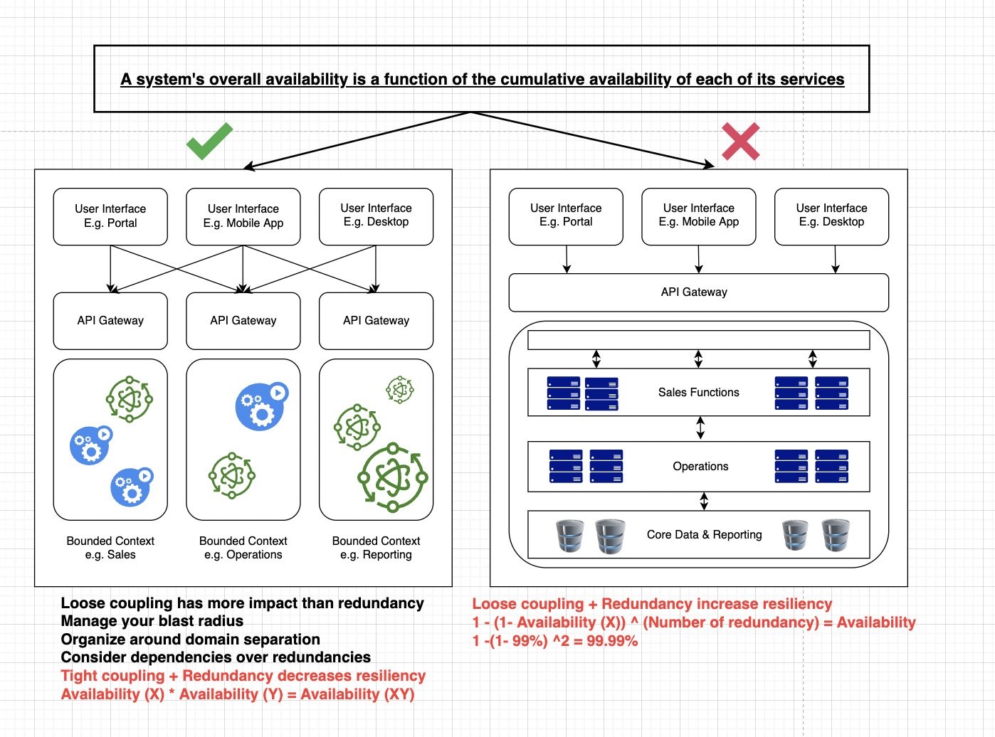
In Part 3, we explore how to develop resilient applications, and the need to test and break our operational processes and run books. Processes are needed to capture baseline metrics and boundary conditions. Detecting deviations from accepted baselines requires logging, distributed tracing, monitoring, and alerting. Testing automation and rollback are part of continuous integration/continuous deployment (CI/CD) pipelines. Keeping track of network, application, and system health requires automation.

In order to meet recovery time and point objective (RTO and RPO, respectively) requirements of distributed applications, we need automation to implement failover operations across multiple layers. Let’s explore how a distributed system’s operational resiliency needs to be addressed before it goes into production, after it’s live in production, and when a failure happens.

Pattern 1: Standardize and automate AWS account setup

Create processes and automation for onboarding users and providing access to AWS accounts according to their role and business unit, as defined by the organization. Federated access to AWS accounts and organizations simplifies cost management, security implementation, and visibility. Having a strategy for a suitable AWS account structure can reduce the blast radius in case of a compromise.

  1. Have auditing mechanisms in place. AWS CloudTrail monitors compliance, improving security posture, and auditing all the activity records across AWS accounts.
  2. Practice the least privilege security model when setting up access to the CloudTrail audit logs plus network and applications logs. Follow best practices on service control policies and IAM boundaries to help ensure your AWS accounts stay within your organization’s access control policies.
  3. Explore AWS Budgets, AWS Cost Anomaly Detection, and AWS Cost Explorer for cost-optimizing techniques. The AWS Compute Optimizer and Instance Scheduler on AWS resource resizing and auto-shutdown for non-working hours. A Beginner’s Guide to AWS Cost Management explores multiple cost-optimization techniques.
  4. Use AWS CloudFormation and AWS Config to detect infrastructure drift and take corrective actions to make resources compliant, as demonstrated in Figure 1.
Compliance control and drift detection

Figure 1. Compliance control and drift detection

Pattern 2: Documenting knowledge about the distributed system

Document high-level infrastructure and dependency maps.

Define availability characteristics of distributed system. Systems have components with varying RTO and RPO needs. Document application component boundaries and capture dependencies with other infrastructure components, including Domain Name System (DNS), IAM permissions; and access patterns, secrets, and certificates. Discover dependencies through solutions, such as Workload Discovery on AWS, to plan resiliency methods and ensure the order of execution of various steps during failover are correct.

Capture non-functional requirements (NFRs), such as business key performance indicators (KPIs), RTO, and RPO, for your composing services. NFRs are quantifiable and define system availability, reliability, and recoverability requirements. They should include throughput, page-load, and response time requirements. Quantify the RTO and RPO of different components of the distributed system by defining them. The KPIs measure if you are meeting the business objectives. As mentioned in Part 2: Infrastructure layer, RTO and RPO help define the failover and data recovery procedures.

Pattern 3: Define CI/CD pipelines for application code and infrastructure components

Establish a branching strategy. Implement automated checks for version and tagging compliance in feature/sprint/bug fix/hot fix/release candidate branches, according to your organization’s policies. Define appropriate release management processes and responsibility matrices, as demonstrated in Figures 2 and 3.

Test at all levels as part of an automated pipeline. This includes security, unit, and system testing. Create a feedback loop that provides the ability to detect issues and automate rollback in case of production failures, which are indicated by business KPI negative impact and other technical metrics.

Define the release management process

Figure 2. Define the release management process

Sample roles and responsibility matrix

Figure 3. Sample roles and responsibility matrix

Pattern 4: Keep code in a source control repository, regardless of GitOps

Merge requests and configuration changes follow the same process as application software. Just like application code, manage infrastructure as code (IaC) by checking the code into a source control repository, submitting pull requests, scanning code for vulnerabilities, alerting and sending notifications, running validation tests on deployments, and having an approval process.

You can audit your infrastructure drift, design reusable and repeatable patterns, and adhere to your distributed application’s RTO objectives by building your IaC (Figure 4). IaC is crucial for operational resilience.

CI/CD pipeline for deploying IaC

Figure 4. CI/CD pipeline for deploying IaC

Pattern 5: Immutable infrastructure

An immutable deployment pipeline launches a set of new instances running the new application version. You can customize immutability at different levels of granularity depending on which infrastructure part is being rebuilt for new application versions, as in Figure 5.

The more immutable infrastructure components being rebuilt, the more expensive deployments are in both deployment time and actual operational costs. Immutable infrastructure also is easier to rollback.

Different granularity levels of immutable infrastructure

Figure 5. Different granularity levels of immutable infrastructure

Pattern 6: Test early, test often

In a shift-left testing approach, begin testing in the early stages, as demonstrated in Figure 6. This can surface defects that can be resolved in a more time- and cost-effective manner compared with after code is released to production.

Shift-left test strategy

Figure 6. Shift-left test strategy

Continuous testing is an essential part of CI/CD. CI/CD pipelines can implement various levels of testing to reduce the likelihood of defects entering production. Testing can include: unit, functional, regression, load, and chaos.

Continuous testing requires testing and breaking existing boundary conditions, and updating test cases if the boundaries have changed. Test cases should test distributed systems’ idempotency. Chaos testing benefits our incidence response mechanisms for distributed systems that have multiple integration points. By testing our auto scaling and failover mechanisms, chaos testing improves application performance and resiliency.

AWS Fault Injection Simulator (AWS FIS) is a service for chaos testing. An experiment template contains actions, such as StopInstance and StartInstance, along with targets on which the test will be performed. In addition, you can mention stop conditions and check if they triggered the required Amazon CloudWatch alarms, as demonstrated in Figure 7.

AWS Fault Injection Simulator architecture for chaos testing

Figure 7. AWS Fault Injection Simulator architecture for chaos testing

Pattern 7: Providing operational visibility

In production, operational visibility across multiple dimensions is necessary for distributed systems (Figure 8). To identify performance bottlenecks and failures, use AWS X-Ray and other open-source libraries for distributed tracing.

Write application, infrastructure, and security logs to CloudWatch. When metrics breach alarm thresholds, integrate the corresponding alarms with Amazon Simple Notification Service or a third-party incident management system for notification.

Monitoring services, such as Amazon GuardDuty, are used to analyze CloudTrail, virtual private cloud flow logs, DNS logs, and Amazon Elastic Kubernetes Service audit logs to detect security issues. Monitor AWS Health Dashboard for maintenance, end-of-life, and service-level events that could affect your workloads. Follow the AWS Trusted Advisor recommendations to ensure your accounts follow best practices.

Dimensions for operational visibility

Figure 8. Dimensions for operational visibility (click the image to enlarge)

Figure 9 explores various application and infrastructure components integrating with AWS logging and monitoring components for increased problem detection and resolution, which can provide operational visibility.

Tooling architecture to provide operational visibility

Figure 9. Tooling architecture to provide operational visibility

Having an incident response management plan is an important mechanism for providing operational visibility. Successful execution of this requires educating the stakeholders on the AWS shared responsibility model, simulation of anticipated and unanticipated failures, documentation of the distributed system’s KPIs, and continuous iteration. Figure 10 demonstrates the features of a successful incidence response management plan.

An incidence response management plan

Figure 10. An incidence response management plan (click the image to enlarge)

Conclusion

In Part 3, we discussed continuous improvement of our processes by testing and breaking them. In order to understand the baseline level metrics, service-level agreements, and boundary conditions of our system, we need to capture NFRs. Operational capabilities are required to capture deviations from baseline, which is where alerting, logging, and distributed tracing come in. Processes should be defined for automating frequent testing in CI/CD pipelines, detecting network issues, and deploying alternate infrastructure stacks in failover regions based on RTOs and RPOs. Automating failover steps depends on metrics and alarms, and by using chaos testing, we can simulate failover scenarios.

Prepare for failure, and learn from it. Working to maintain resilience is an ongoing task.

Want to learn more?

A multi-dimensional approach helps you proactively prepare for failures, Part 2: Infrastructure layer

Post Syndicated from Piyali Kamra original https://aws.amazon.com/blogs/architecture/a-multi-dimensional-approach-helps-you-proactively-prepare-for-failures-part-2-infrastructure-layer/

Distributed applications resiliency is a cumulative resiliency of applications, infrastructure, and operational processes. Part 1 of this series explored application layer resiliency. In Part 2, we discuss how using Amazon Web Services (AWS) managed services, redundancy, high availability, and infrastructure failover patterns based on recovery time and point objectives (RTO and RPO, respectively) can help in building more resilient infrastructures.

Pattern 1: Recognize high impact/likelihood infrastructure failures

To ensure cloud infrastructure resilience, we need to understand the likelihood and impact of various infrastructure failures, so we can mitigate them. Figure 1 illustrates that most of the failures with high likelihood happen because of operator error or poor deployments.

Automated testing, automated deployments, and solid design patterns can mitigate these failures. There could be datacenter failures—like whole rack failures—but deploying applications using auto scaling and multi-availability zone (multi-AZ) deployment, plus resilient AWS cloud native services, can mitigate the impact.

Likelihood and impact of failure events

Figure 1. Likelihood and impact of failure events

As demonstrated in the Figure 1, infrastructure resiliency is a combination of high availability (HA) and disaster recovery (DR). HA involves increasing the availability of the system by implementing redundancy among the application components and removing single points of failure.

Application layer decisions, like creating stateless applications, make it simpler to implement HA at the infrastructure layer by allowing it to scale using Auto Scaling groups and distributing the redundant applications across multiple AZs.

Pattern 2: Understanding and controlling infrastructure failures

Building a resilient infrastructure requires understanding which infrastructure failures are under control and which ones are not, as demonstrated in Figure 2.

These insights allow us to automate the detection of failures, control them, and employ pro-active patterns, such as static stability, to mitigate the need to scale up the infrastructure by over-provisioning it in advance.

Proactively designing systems in the event of failure

Figure 2. Proactively designing systems in the event of failure

The infrastructure decisions under our control that can increase the infrastructure resiliency of our system, include:

  • AWS services have control and data planes designed for minimum blast radius. Data planes typically have higher availability design goals than control planes and are usually less complex. When implementing recovery or mitigation responses to events that can affect resiliency, using control plane operations can lower the overall resiliency of your architectures. For example, Amazon Route 53 (Route 53) has a data plane designed for a 100% availability SLA. A good fail-over mechanism should rely on the data plane and not the control plane, as explained in Creating Disaster Recovery Mechanisms Using Amazon Route 53.
  • Understanding networking design and routes implemented in a virtual private cloud (VPC) are critical when testing the flow of traffic in our application. Understanding the flow of traffic helps us design better applications and see how one component failure can affect overall ingress/egress traffic. To achieve better network resiliency, it’s important to implement a good subnet strategy and manage our IP addresses to avoid fail-over issues and asymmetric routing in hybrid architectures. Use IP address management tools for established subnet strategies and routing decisions.
  • When designing VPCs and AZs, understanding the service limits, deploying independent routing tables and components in each zone increases availability. For example, highly available NAT gateways are preferred over NAT instances, as noted in the comparison provided in the Amazon VPC documentation.

Pattern 3: Considering different ways of increasing HA at the infrastructure layer

As already detailed, infrastructure resiliency = HA + DR.

Different ways by which system availability can be increased include:

  • Building for redundancy: Redundancy is the duplication of application components to increase the overall availability of the distributed system. After following application layer best practices, we can build auto healing mechanisms at the infrastructure layer.

We can take advantage of auto scaling features and use Amazon CloudWatch metrics and alarms to set up auto scaling triggers and deploy redundant copies of our applications across multiple AZs. This protects workloads from AZ failures, as shown in Figure 3.

Redundancy increases availability

Figure 3. Redundancy increases availability

  • Auto scale your infrastructure: When there are AZ failures, infrastructure auto scaling maintains the desired number of redundant components, which helps maintain the base level application throughput. This way, HA system and manage costs are maintained. Auto scaling uses metrics to scale in and out, appropriately, as shown in Figure 4.
How auto scaling improves availability

Figure 4. How auto scaling improves availability

  • Implement resilient network connectivity patterns: While building highly resilient distributed systems, network access to AWS infrastructure also needs to be highly resilient. While deploying hybrid applications, the capacity needed for hybrid applications to communicate with their cloud native application counterparts is an important consideration in designing the network access using AWS Direct Connect or VPNs.

Testing failover and fallback scenarios helps validate that network paths operate as expected and routes fail over as expected to meet RTO objectives. As the number of connection points between the data center and AWS VPCs increases, a hub and spoke configuration provided by the Direct Connect gateway and transit gateways simplify network topology, testing, and fail over. For more information, visit the AWS Direct Connect Resiliency Recommendations.

  • Whenever possible, use the AWS networking backbone to increase security, resiliency, and lower cost. AWS PrivateLink provides secure access to AWS services and exposes the application’s functionalities and APIs to other business units or partner accounts hosted on AWS.
  • Security appliances need to be set up in HA configuration, so that even if one AZ is unavailable, security inspection can be taken over by the redundant appliances in the other AZs.
  • Think ahead about DNS resolution: DNS is a critical infrastructure component; hybrid DNS resolution should be designed carefully with Route 53 HA inbound and outbound resolver endpoints instead of using self-managed proxies.

Implement a good strategy to share DNS resolver rules across AWS accounts and VPC’s with Resource Access Manager. Network failover tests are an important part of Disaster Recovery and Business Continuity Plans. To learn more, visit Set up integrated DNS resolution for hybrid networks in Amazon Route 53.

Additionally, ELB uses health checks to make sure that requests will route to another component if the underlying traffic application component fails. This improves the distributed system’s availability, as it is the cumulative availability of all different layers in our system. Figure 5 details advantages of some AWS managed services.

AWS managed services help in building resilient infrastructures (click the image to enlarge)

Figure 5. AWS managed services help in building resilient infrastructures (click the image to enlarge)

Pattern 4: Use RTO and RPO requirements to determine the correct failover strategy for your application

Capture RTO and RPO requirements early on to determine solid failover strategies (Figure 6). Disaster recovery strategies within AWS range from low cost and complexity (like backup and restore), to more complex strategies when lower values of RTO and RPO are required.

In pilot light and warm standby, only the primary region receives traffic. Pilot light only critical infrastructure components run in the backup region. Automation is used to check failures in the primary region using health checks and other metrics.

When health checks fail, use a combination of auto scaling groups, automation, and Infrastructure as Code (IaC) for quick deployment of other infrastructure components.

Note: This strategy depends on control plane availability in the secondary region for deploying the resources; keep this point in mind if you don’t have compute pre-provisioned in the secondary region. Carefully consider the business requirements and a distributed system’s application-level characteristics before deciding on a failover strategy. To understand all the factors and complexities involved in each of these disaster recovery strategies refer to disaster recovery options in the cloud.

Relationship between RTO, RPO, cost, data loss, and length of service interruption

Figure 6. Relationship between RTO, RPO, cost, data loss, and length of service interruption

Conclusion

In Part 2 of this series, we discovered that infrastructure resiliency is a combination of HA and DR. It is important to consider likelihood and impact of different failure events on availability requirements. Building in application layer resiliency patterns (Part 1 of this series), along with early discovery of the RTO/RPO requirements, as well as operational and process resiliency of an organization helps in choosing the right managed services and putting in place the appropriate failover strategies for distributed systems.

It’s important to differentiate between normal and abnormal load threshold for applications in order to put automation, alerts, and alarms in place. This allows us to auto scale our infrastructure for normal expected load, plus implement corrective action and automation to root out issues in case of abnormal load. Use IaC for quick failover and test failover processes.

Stay tuned for Part 3, in which we discuss operational resiliency!

A multi-dimensional approach helps you proactively prepare for failures, Part 1: Application layer

Post Syndicated from Piyali Kamra original https://aws.amazon.com/blogs/architecture/a-multi-dimensional-approach-helps-you-proactively-prepare-for-failures-part-1-application-layer/

Resiliency of applications surpasses everything else in building customer trust. Because of this, it cannot be an afterthought. Instead of simply reacting to a failure, why not be proactive?

As your system expands, you’ll likely encounter issues that can hinder your ability to scale, like security and cost. So, it’s necessary to think about the correct architectural patterns beforehand to minimize your chances of enduring a failure without a recovery plan.

In this multi-part blog series, we’ll show you how to take a multi-dimensional approach to ensure your applications, infrastructure, and operational processes can detect points of failure and can gracefully react if (and inevitably when) a failure occurs.

In each part of the series, we recommend resiliency architecture patterns and managed services to apply across all layers of your distributed system to create a production-ready, resilient application. This post, Part 1, examines how to create application layer resiliency.

Example use case

To illustrate our recommendations for building an effective distributed system, we’ll consider a simple order payment system. Figure 1 shows our base implementation. The real-time part of the distributed system is built with:

This system is transactional so far, but we need to aggregate and analyze data. We do this using Amazon Simple Queue Service (Amazon SQS), AWS Lambda, AWS Step Functions, Amazon S3, and Amazon Athena. Amazon Kinesis Data Firehose and Amazon Redshift populate the data warehouse via their data pipelines. Amazon QuickSight helps us visualize the data.

Architecture components of a distributed system

Figure 1. Architecture components of a distributed system

Next, let’s look into distributed architectural patterns we could apply to the base implementation to bolster resiliency and common tradeoffs you need to consider for each.

Pattern 1: Microservices

Microservices are building blocks for smaller, domain-specific services. As shown in the Microservices on AWS whitepaper, microservices offer many benefits. They reduce the blast radius of any failure, require smaller teams to manage them, and simplify deployment pipelines to get them into production.

Tradeoffs and their workarounds

If your distributed system is comprised of several smaller services, a failure or inability to respond to failures in one service might affect other services in the chain.

To help with this, consider implementing one or more of the following patterns.

Circuit breaker pattern

Like an electrical circuit breaker, the circuit breaker pattern stops cascading failures. You can implement it as an orchestrator, at an individual microservice level, and/or in a service mesh across multiple services to detect timeouts and track failures across services, which prevents a distributed system from getting overwhelmed.

Retries with exponential backoff and jitter

A common way to handle database timeouts is to implement retries. However, if all the transactions retry at the same interval, it might choke the network bandwidth and throttle the database.

We recommend introducing exponential backoff and jitter to the retries and to introduce an element of randomness in the retry interval.

Let’s see this in action. Consider the backend implementation of the order payment system in our example use case, as shown in Figure 2.

Backend processing of order payment system

Figure 2. Backend processing of order payment system

For incoming orders, the payment process must succeed for the order to be processed. To ensure latency in the payments database writes does not affect the transactions that read from the database for the order processing UI:

  1. Isolate reads and writes with a read-replica
  2. Use an Amazon RDS Proxy to handle connection pools and use throttling to help with preventing database congestion and locking
  3. Introduce exponential backoff to increase the time between subsequent retries of failed requests. Combine this approach with “jitter” to prevent large bursts of retries

Figure 3 compares recovery time with exponential backoff to exponential backoff combined with jitter:

Recovery time graph for exponential backoff with and without jitter

Figure 3. Recovery time graph for exponential backoff with and without jitter

Health checks and feature flags

If you’ve deployed new functionality in production and it doesn’t work as expected, use feature flags to turn it off rather than roll back the deployment. This helps you reduce operational complexity and downtime. See the Automating safe, hands-off deployments article for more information.

The load balancer uses periodic automatic health checks to determine if the backend service is healthy and can serve traffic. Figure 4 shows you where to use shallow and deep health checks:

  • Use shallow health checks to probe for host/local failures on a server resource (for example, liveliness checks).
  • Probing for dependency failures needs a deep health check. Deep health checks will give you a better understanding of the health of the system, but they’re expensive, and a dependency check failure can cause cascading failure throughout the system.
Shallow vs deep health checks

Figure 4. Shallow vs deep health checks

Pattern 2: Saga pattern

A saga pattern keeps your data consistent across microservices when a transaction spans multiple services. It updates each service with a message or event to prompt the service to move to the next transaction step.

For example, in our order payment system, a transaction is considered successful if the payment for that order is processed.

Tradeoffs and their workarounds

The saga pattern is great for long transactions. However, if a step in the process cannot complete, you’ll need compensating transactions in place to undo any changes from previous steps. For example, as shown in Figure 5, if the payment fails, the customer’s order must be canceled.

The saga pattern coordinates transactions across a system of microservices

Figure 5. The saga pattern coordinates transactions across a system of microservices

Consider implementing the following pattern to set up compensating transactions.

Serverless saga pattern with Step Functions

We recommend using a serverless orchestrator in Step Functions to roll back to a previous step in an order. Figure 6 shows the serverless orchestrator and how its lightweight, centralized control service coordinates the flow across microservices. It performs compensating transactions during failure scenarios to ensure that if one microservice fails, the others will not.

Step Functions as serverless orchestrators

Figure 6. Step Functions as serverless orchestrators

Pattern 3: Event-driven architecture

An event-driven architecture uses events to communicate between decoupled services. By decoupling your services, they are only aware of the event router, not each other. This means that your services are interoperable, but if one service has a failure, the rest will keep running. The event router acts as an elastic buffer that will accommodate surges in workloads.

Tradeoffs and their workarounds

An event-driven architecture provides multiple implementation options. Carefully consider your system’s distinct attributes and scaling and performance needs to decide on a suitable approach.

The mind map in Figure 7 shows when to use an event-driven pattern, our recommendations for implementation, tradeoffs and their workarounds, and anti-patterns:

Decision criteria for event-driven architecture pattern

Figure 7. Decision criteria for event-driven architecture pattern (click the image to enlarge)

Pattern 4: Cache pattern

Deploying stateless redundant copies of your application components, along with using distributed caches, can improve the availability of your system. This allows your infrastructure to scale in response to user requests.

Tradeoffs and their workarounds

Caches have multiple configuration options. Carefully consider your system’s distinct attributes and scaling and performance needs to decide on a suitable approach.

The mind map in Figure 8 shows when to use a cache pattern, our recommendations for implementation, tradeoffs and their workarounds, and anti-patterns:

Decision criteria for cache pattern

Figure 8. Decision criteria for cache pattern (click the image to enlarge)

Improving application resiliency with bounded contexts

Loosely coupled services improve availability more than only creating redundant copies of your applications. Figure 9 shows the benefits of a loosely coupled system versus a tightly coupled system.

Relationship between loose coupling and availability

Figure 9. Relationship between loose coupling and availability

Conclusion

In this post, we learned about various architecture patterns and their tradeoffs, and provided recommendations on how to gracefully mitigate failures before they happen.

Distributed systems can use all of these patterns, which helps improve resiliency at the application layer. Applying these patterns, along with the Infrastructure and Operations improvements discussed in parts 2 and 3, will provide frameworks for resilient applications.