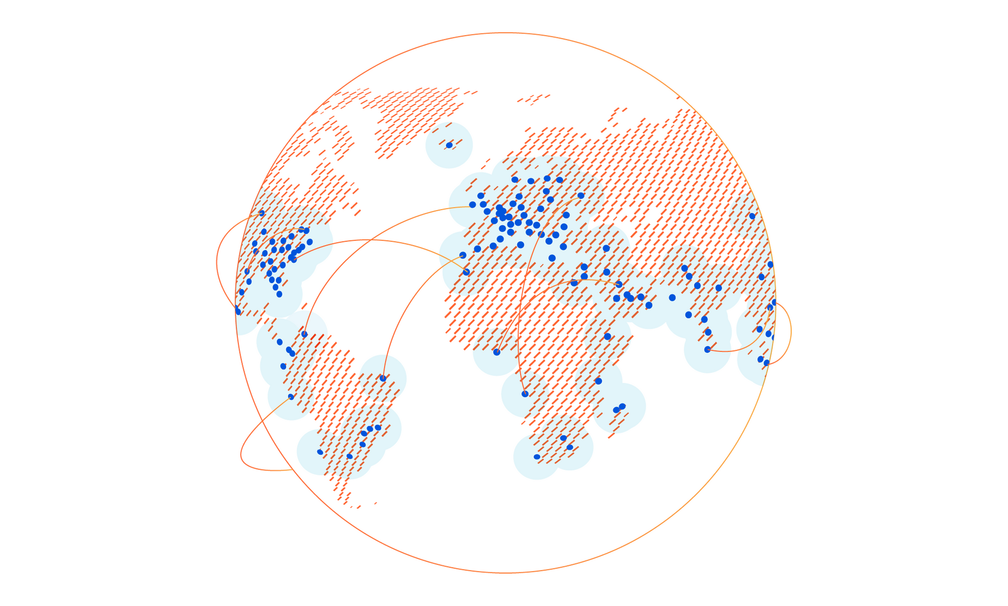
Cloudflare’s global network is always expanding, and 2021 has been no exception. Today, I’m happy to give a mid-year update: we’ve added ten new Cloudflare cities, with four new countries represented among them. And we’ve doubled our computational footprint since the start of pandemic-related lockdowns.
No matter what else we do at Cloudflare, constant expansion of our infrastructure to new places is a requirement to help build a better Internet. 2021, like 2020, has been a difficult time to be a global network — from semiconductor shortages to supply-chain disruptions — but regardless, we have continued to expand throughout the entire globe, experimenting with technologies like ARM, ASICs, and Nvidia all the way.
The Cities
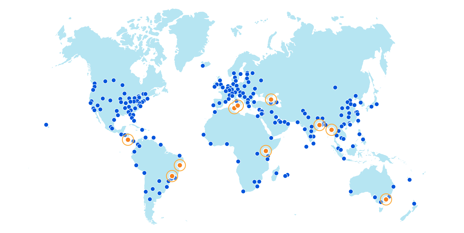
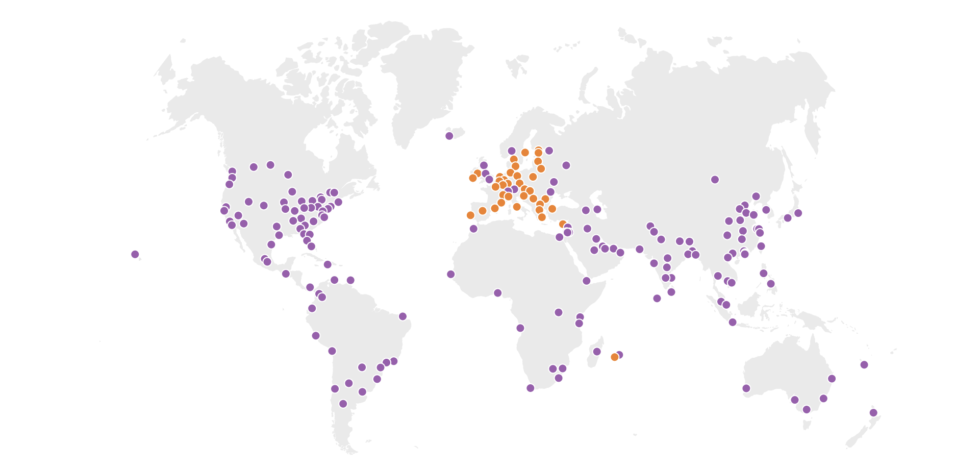
Without further ado, here are the new Cloudflare cities: Tbilisi, Georgia; San José, Costa Rica; Tunis, Tunisia; Yangon, Myanmar; Nairobi, Kenya; Jashore, Bangladesh; Canberra, Australia; Palermo, Italy; and Salvador and Campinas, Brazil.
These deployments are spread across every continent except Antarctica.
We’ve solidified our presence in every country of the Caucuses with our first deployment in the country of Georgia in the capital city of Tbilisi. And on the other side of the world, we’ve also established our first deployment in Costa Rica’s capital of San José with NIC.CR, run by the Academia Nacional de Ciencias.
In the northernmost country in Africa comes another capital city deployment, this time in Tunis, bringing us one country closer towards fully circling the Mediterranean Sea. Wrapping up the new country docket is our first city in Myanmar with our presence in Yangon, the country’s capital and largest city.
Our second Kenyan city is the country’s capital, Nairobi, bringing our city count in sub-Saharan Africa to a total of fifteen. In Bangladesh, Jashore puts us in the capital of its namesake Jashore District and the third largest city in the country after Chittagong and Dhaka, both already Cloudflare cities.
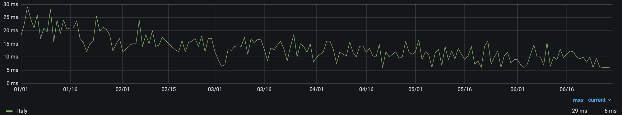
In the land way down under, our Canberra deployment puts us in Australia’s capital city, located, unsurprisingly, in the Australian Capital Territory. In differently warm lands is Palermo, Italy, capital of the island of Sicily, which we already see boosting performance throughout Italy.
25th percentile latency of non-bot traffic in Italy, year-to-date.
Finally, we’ve gone live in Salvador (capital of the state of Bahia) and Campinas, Brazil, the only city announced today that isn’t a capital. These are some of the first few steps in a larger Brazilian expansion — watch this blog for more news on that soon.
This is in addition to the dozens of new cities we’ve added in Mainland China with our partner, JD Cloud, with whom we have been working closely to quickly deploy and test new cities since last year.
The Impact
While we’re proud of our provisioning process, the work with new cities begins, not ends, with deployment. Each city is not only a new source of opportunity, but risk: Internet routing is fickle, and things that should improve network quality don’t always do so. While we have always had a slew of ways to track performance, we’ve found that a significant, constant improvement in the 25th percentile latency of non-bot traffic to be an ideal approximation of latency impacted by only physical distance.
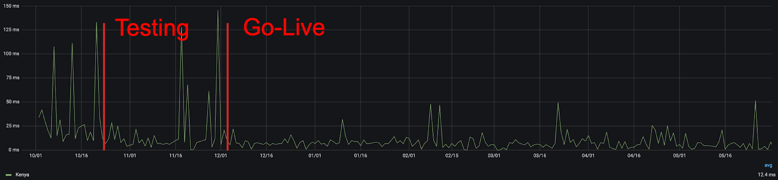
Using this metric, we can quickly see the improvement that comes from adding new cities. For example, in Kenya, we can see that the addition of our Nairobi presence improved real user performance:
25th percentile latency of non-bot Kenyan traffic, before and after Nairobi gained a Cloudflare point of presence.
Latency variations in general are expected on the Internet — particularly in countries with high amounts of Internet traffic originating from non-fixed connections, like mobile phones — but in aggregate, the more consistently low latency, the better. From this chart, you can clearly see that not only was there a reduction in latency, but also that there were fewer frustrating variations in user latency. We all get annoyed when a page loads quickly one second and slowly the next, and the lower jitter that comes with being closer to the server helps to eliminate it.
As a reminder, while these measurements are in thousandths of a second, they add up quickly. Popular sites often require hundreds of individual requests for assets, some of which are initiated serially, so the difference between 25 milliseconds and 5 milliseconds can mean the difference between single and multi-second page load times.
To sum things up, users in the cities or greater areas of these cities should expect an improved Internet experience when using everything from our free, private 1.1.1.1 DNS resolver to the tens of millions of Internet properties that trust Cloudflare with their traffic. We have dozens more cities in the works at any given time, including now. Watch this space for more!
Join Our Team
Like our network, Cloudflare continues to rapidly grow. If working at a rapidly expanding, globally diverse company interests you, we’re hiring for scores of positions, including in the Infrastructure group. Or, if you work at a global ISP and would like to improve your users’ experience and be part of building a better Internet, get in touch with our Edge Partners Program at [email protected] we’ll look into sending some servers your way!
Today we’re excited to announce the Cloudflare Data Localization Suite, which helps businesses get the performance and security benefits of Cloudflare’s global network, while making it easy to set rules and controls at the edge about where their data is stored and protected.
The Data Localization Suite is available now as an add-on for Enterprise customers.
Cloudflare’s network is private and compliant by design. Preserving end-user privacy is core to our mission of helping to build a better Internet; we’ve never sold personal data about customers or end users of our network. We comply with laws like GDPR and maintain certifications such as ISO-27001.
Today, we’re announcing tools that make it simple for our customers to build the same rigor into their own applications. In this post, I’ll explain the different types of data that we process and how the Data Localization Suite keeps this data local.
We’ll also talk about how Cloudflare makes it possible to build applications that comply with data locality laws, while remaining fast, secure and scalable.
Why keep data local?
Cloudflare’s customers have increasing desire or face legal requirements for data locality: they want to control the geographic location where their data is handled. Many categories of data that our customers process (including healthcare, legal, or financial data) may be subject to obligations that specify the data be stored or processed in a specific location. The preference or requirement for data localization is growing across jurisdictions such as the EU, India, and Brazil; over time, we expect more customers in more places will be expected to keep data local.
Although “data locality” sounds like a simple concept, our conversations with Cloudflare customers make clear that there are a number of unique challenges they face in the attempt to move toward this goal. The availability of information on their Internet properties will remain global–they don’t want to limit access to their websites to local jurisdictions–but they want to make sure data stays local. Variously, they are trying to figure out:
How do I build local requirements into my global online operations?
How do I make sure unencrypted traffic is only available locally?
How do I make sure personal data is handled according to localization obligations?
How do I make sure my applications only store data in certain locations?
The Cloudflare Data Localization Suite attempts to respond to these questions.
Until now, customers who wanted to localize their data had to choose to restrict their application to one data center, or to one cloud provider’s region. This is a fragile approach, fraught with performance, reliability, and security challenges. Cloudflare is creating a new paradigm: customers should be able to get the performance and security benefits of our global network, while effortlessly keeping their data local.
Encryption is the backbone of privacy
Before we go into data locality, we should discuss encryption. Privacy isn’t possible without strong encryption; otherwise, anyone could snoop your customers’ data, regardless of where it’s stored.
Data is often described as being “in transit” and “at rest”. It’s critically important that both are encrypted. Data “in transit” refers to just that—data while it’s moving about on the wire, whether a local network or the public Internet. “At rest” generally means stored on a disk somewhere, whether a spinning HDD or a modern SSD.
In transit, Cloudflare can enforce that all traffic to end-users uses modern TLS and gets the highest level of encryption possible. We can also enforce that all traffic back to customers’ origin servers is always encrypted. Communication between all our edge and core data centers is always encrypted.
Cloudflare encrypts all of the data we handle at rest, usually with disk-level encryption. From cached files on our edge network, to configuration state in databases in our core data centers—every byte is encrypted at rest.
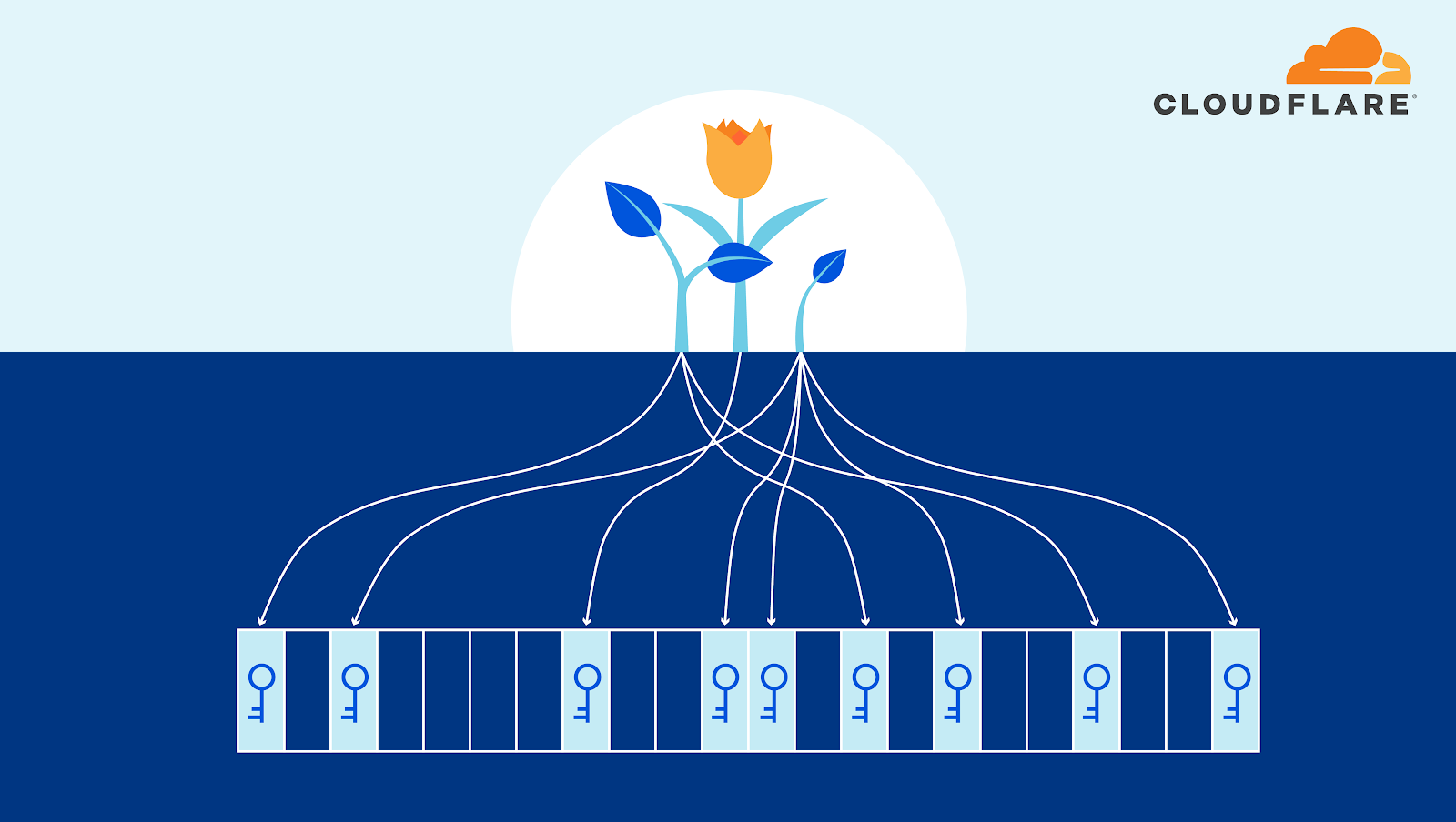
Control where TLS private keys can be accessed
Given the importance of encryption, one of the most sensitive pieces of data that our customers trust us to protect are their cryptographic keys, which enable data to be decrypted. Cloudflare offers two ways for customers to ensure that their private keys are only accessible in locations they specify.
Keyless SSL allows a customer to store and manage their own SSL private keys for use with Cloudflare on any external infrastructure of their choosing. Customers can use a variety of systems for their keystore, including hardware security modules (“HSMs”), virtual servers, and hardware running Unix/Linux and Windows that is housed in environments customers control. Cloudflare never has access to the private key with Keyless SSL.
Geo Key Manager gives customers granular control over which locations should store their keys. For example, a customer can choose for the private keys required for inspection of traffic to only be accessible inside data centers located in the European Union.
Manage where HTTPS requests and responses are inspected
In order to deploy our WAF, or detect malicious bot traffic, Cloudflare must terminate TLS in our edge data centers and inspect HTTPS request and response payloads.
Regional Services gives organizations control over where their traffic is inspected. With Regional Services enabled, traffic is ingested on Cloudflare’s global Anycast network at the location closest to the client, where we can provide L3 and L4 DDoS protection. Instead of being inspected at the HTTP level at that data center, this traffic is securely transmitted to Cloudflare data centers inside the region selected by the customer and handled there.
Control the logs and analytics generated by your traffic
In addition to making our customers’ infrastructure and teams faster, more secure, and more reliable, we also provide insights into what our services do, and how customers can make better use of them. We gather metadata about the traffic that goes through our edge data centers, and use this to improve the operation of our own network: for example, by crafting WAF rules to block the latest attacks, or by developing machine learning models to detect malicious bots. We also make this data available to our customers in the form of logs and analytics.
This only requires a subset of the metadata to be processed in our core data centers in the US/EU. This data contains information about how many requests were served, how much data was sent, how long requests took, and other information that is essential for the operation of our network.
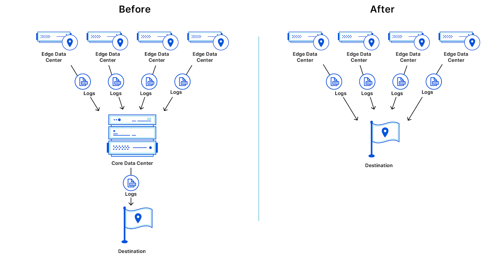
With Edge Log Delivery, customers can send logs directly from the edge to their partner of choice—for example, an Azure storage bucket in their preferred region, or an instance of Splunk that runs in an on-premise data center. With this option, customers can still get their complete logs in their preferred region, without these logs first flowing through either of our US or EU core data centers.
Edge Log Delivery is in early beta for Enterprise customers today—please visit our product page for more information.
Ultimately, we are working towards providing customers full control over where their metadata is stored, and for how long. In the coming year, we plan to allow customers to be able to choose exactly which fields are stored, and for how long, and in which location.
Building location-aware applications from the ground up
So far, we’ve discussed how Cloudflare’s products can offer global performance and security solutions for our customers, while keeping their existing keys, application data, and metadata local.
But we know that customers are also struggling to use existing, traditional cloud systems to manage their data locality needs. Existing platforms may allow code or data to be deployed to a specific region, but having copies of applications in each region, and managing state across each of them, can be challenging at best (or impossible at worst).
The ultimate promise of serverless has been to allow any developer to say “I don’t care where my code runs, just make it scale.” Increasingly, another promise will need to be “I do care where my code runs, and I need more control to satisfy my compliance department.” Cloudflare Workers allows you the best of both worlds, with instant scaling, locations that span more than 100 countries around the world, and the granularity to choose exactly what you need.
We are announcing a major improvement that lets customers control where their applications store data: Workers Durable Objects will support Jurisdiction Restrictions. Durable Objects provide globally consistent state and coordination to serverless applications running on the Cloudflare Workers platform. Jurisdiction Restrictions will make it possible for users to ensure that their Durable Objects do not store data or run outside of a given jurisdiction—making it trivially simple to build applications that combine global performance with local compliance. With automatic migration of Durable Objects, adapting to new rules will be as simple as adding a tag to a set of Durable Objects.
Building for the long haul
The data localization landscape is constantly evolving. Since we began working on the Data Localization Suite, the European Data Protection Board has released new guidance about how data may be transferred between the EU and the US. And we know this is just the beginning — over time, more regions and more industries will have data localization requirements.
At Cloudflare, we stay on top of the latest developments around data protection so our customers don’t have to. The Data Localization Suite gives our customers the tools to set rules and controls at the edge about where their data is stored and protected, while taking advantage of our global network.
As a security company, we pride ourselves on finding innovative ways to protect our platform to, in turn, protect the data of our customers. Part of this approach is implementing progressive methods in protecting our hardware at scale. While we have blogged about how we address security threats from application to memory, the attacks on hardware, as well as firmware, have increased substantially. The data cataloged in the National Vulnerability Database (NVD) has shown the frequency of hardware and firmware-level vulnerabilities rising year after year.
Technologies like secure boot, common in desktops and laptops, have been ported over to the server industry as a method to combat firmware-level attacks and protect a device’s boot integrity. These technologies require that you create a trust ‘anchor’, an authoritative entity for which trust is assumed and not derived. A common trust anchor is the system Basic Input/Output System (BIOS) or the Unified Extensible Firmware Interface (UEFI) firmware.
While this ensures that the device boots only signed firmware and operating system bootloaders, does it protect the entire boot process? What protects the BIOS/UEFI firmware from attacks?
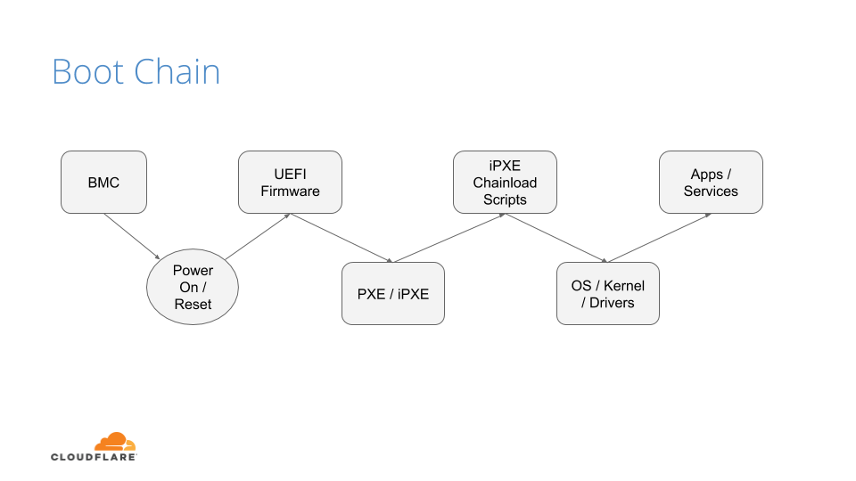
The Boot Process
Before we discuss how we secure our boot process, we will first go over how we boot our machines.
The above image shows the following sequence of events:
After powering on the system (through a baseboard management controller (BMC) or physically pushing a button on the system), the system unconditionally executes the UEFI firmware residing on a flash chip on the motherboard.
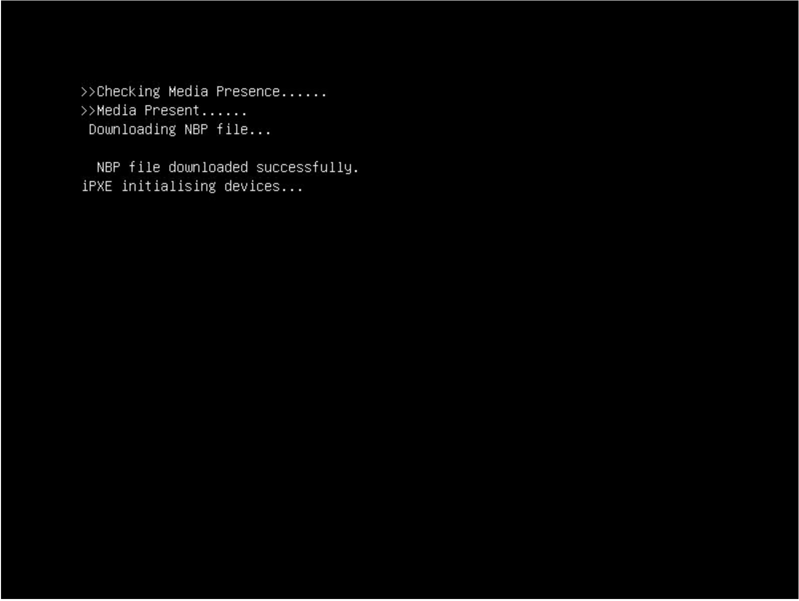
UEFI performs some hardware and peripheral initialization and executes the Preboot Execution Environment (PXE) code, which is a small program that boots an image over the network and usually resides on a flash chip on the network card.
PXE sets up the network card, and downloads and executes a small program bootloader through an open source boot firmware called iPXE.
iPXE loads a script that automates a sequence of commands for the bootloader to know how to boot a specific operating system (sometimes several of them). In our case, it loads our Linux kernel, initrd (this contains device drivers which are not directly compiled into the kernel), and a standard Linux root filesystem. After loading these components, the bootloader executes and hands off the control to the kernel.
Finally, the Linux kernel loads any additional drivers it needs and starts applications and services.
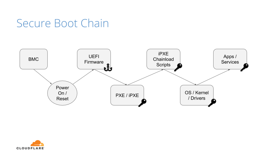
UEFI Secure Boot
Our UEFI secure boot process is fairly straightforward, albeit customized for our environments. After loading the UEFI firmware from the bootloader, an initialization script defines the following variables:
Platform Key (PK): It serves as the cryptographic root of trust for secure boot, giving capabilities to manipulate and/or validate the other components of the secure boot framework.
Trusted Database (DB): Contains a signed (by platform key) list of hashes of all PCI option ROMs, as well as a public key, which is used to verify the signature of the bootloader and the kernel on boot.
These variables are respectively the master platform public key, which is used to sign all other resources, and an allow list database, containing other certificates, binary file hashes, etc. In default secure boot scenarios, Microsoft keys are used by default. At Cloudflare we use our own, which makes us the root of trust for UEFI:
But, by setting our trust anchor in the UEFI firmware, what attack vectors still exist?
UEFI Attacks
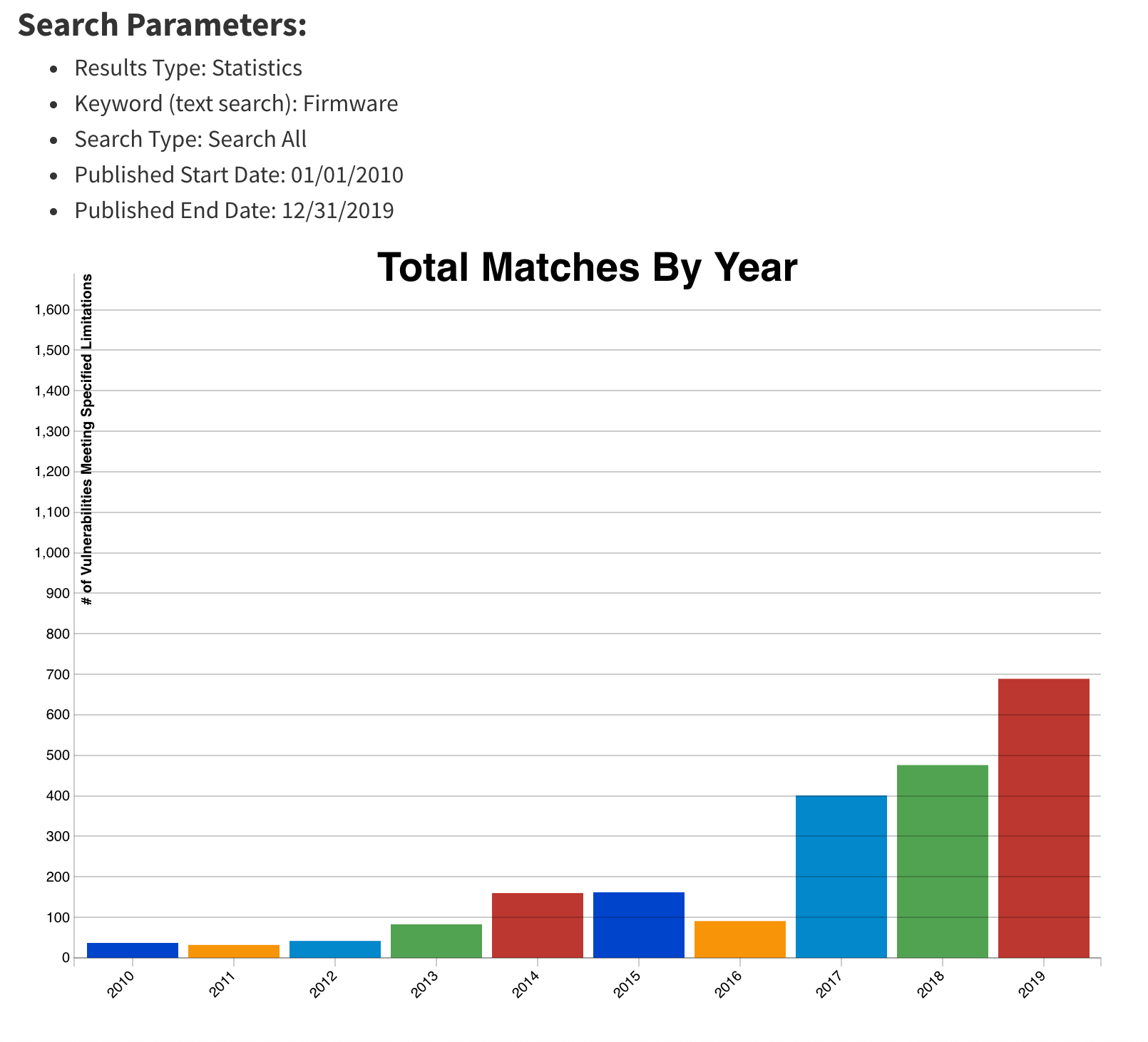
As stated previously, firmware and hardware attacks are on the rise. It is clear from the figure below that firmware-related vulnerabilities have increased significantly over the last 10 years, especially since 2017, when the hacker community started attacking the firmware on different platforms:
This upward trend, coupled with recent malware findings in UEFI, shows that trusting firmware is becoming increasingly problematic.
By tainting the UEFI firmware image, you poison the entire boot trust chain. The ability to trust firmware integrity is important beyond secure boot. For example, if you can’t trust the firmware not to be compromised, you can’t trust things like trusted platform module (TPM) measurements to be accurate, because the firmware is itself responsible for doing these measurements (e.g a TPM is not an on-path security mechanism, but instead it requires firmware to interact and cooperate with). Firmware may be crafted to extend measurements that are accepted by a remote attestor, but that don’t represent what’s being locally loaded. This could cause firmware to have a questionable measured boot and remote attestation procedure.
If we can’t trust firmware, then hardware becomes our last line of defense.
Hardware Root of Trust
Early this year, we made a series of blog posts on why we chose AMD EPYC processors for our Gen X servers. With security in mind, we started turning on features that were available to us and set forth the plan of using AMD silicon as a Hardware Root of Trust (HRoT).
Platform Secure Boot (PSB) is AMD’s implementation of hardware-rooted boot integrity. Why is it better than UEFI firmware-based root of trust? Because it is intended to assert, by a root of trust anchored in the hardware, the integrity and authenticity of the System ROM image before it can execute. It does so by performing the following actions:
Authenticates the first block of BIOS/UEFI prior to releasing x86 CPUs from reset.
Authenticates the System Read-Only Memory (ROM) contents on each boot, not just during updates.
Moves the UEFI Secure Boot trust chain to immutable hardware.
This is accomplished by the AMD Platform Security Processor (PSP), an ARM Cortex-A5 microcontroller that is an immutable part of the system on chip (SoC). The PSB consists of two components:
On-chip Boot ROM
Embeds a SHA384 hash of an AMD root signing key
Verifies and then loads the off-chip PSP bootloader located in the boot flash
Off-chip Bootloader
Locates the PSP directory table that allows the PSP to find and load various images
Authenticates first block of BIOS/UEFI code
Releases CPUs after successful authentication
The PSP secures the On-chip Boot ROM code, loads the off-chip PSP firmware into PSP static random access memory (SRAM) after authenticating the firmware, and passes control to it.
The Off-chip Bootloader (BL) loads and specifies applications in a specific order (whether or not the system goes into a debug state and then a secure EFI application binary interface to the BL)
The system continues initialization through each bootloader stage.
If each stage passes, then the UEFI image is loaded and the x86 cores are released.
Now that we know the booting steps, let’s build an image.
Build Process
Public Key Infrastructure
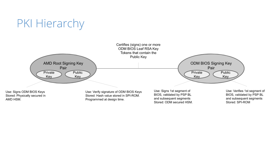
Before the image gets built, a public key infrastructure (PKI) is created to generate the key pairs involved for signing and validating signatures:
Our original device manufacturer (ODM), as a trust extension, creates a key pair (public and private) that is used to sign the first segment of the BIOS (private key) and validates that segment on boot (public key).
On AMD’s side, they have a key pair that is used to sign (the AMD root signing private key) and certify the public key created by the ODM. This is validated by AMD’s root signing public key, which is stored as a hash value (RSASSA-PSS: SHA-384 with 4096-bit key is used as the hashing algorithm for both message and mask generation) in SPI-ROM.
Because of the way the PKI mechanisms are built, the system cannot be compromised if only one of the keys is leaked. This is an important piece of the trust hierarchy that is used for image signing.
Certificate Signing Request
Once the PKI infrastructure is established, a BIOS signing key pair is created, together with a certificate signing request (CSR). Creating the CSR uses known common name (CN) fields that many are familiar with:
countryName
stateOrProvinceName
localityName
organizationName
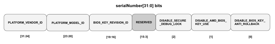
In addition to the fields above, the CSR will contain a serialNumber field, a 32-bit integer value represented in ASCII HEX format that encodes the following values:
PLATFORM_VENDOR_ID: An 8-bit integer value assigned by AMD for each ODM.
PLATFORM_MODEL_ID: A 4-bit integer value assigned to a platform by the ODM.
BIOS_KEY_REVISION_ID: is set by the ODM encoding a 4-bit key revision as unary counter value.
DISABLE_SECURE_DEBUG: Fuse bit that controls whether secure debug unlock feature is disabled permanently.
DISABLE_AMD_BIOS_KEY_USE: Fuse bit that controls if the BIOS, signed by an AMD key, (with vendor ID == 0) is permitted to boot on a CPU with non-zero Vendor ID.
DISABLE_BIOS_KEY_ANTI_ROLLBACK: Fuse bit that controls whether BIOS key anti-rollback feature is enabled.
Remember these values, as we’ll show how we use them in a bit. Any of the DISABLE values are optional, but recommended based on your security posture/comfort level.
AMD, upon processing the CSR, provides the public part of the BIOS signing key signed and certified by the AMD signing root key as a RSA Public Key Token file (.stkn) format.
Putting It All Together
The following is a step-by-step illustration of how signed UEFI firmware is built:
The ODM submits their public key used for signing Cloudflare images to AMD.
AMD signs this key using their RSA private key and passes it back to ODM.
The AMD public key and the signed ODM public key are part of the final BIOS SPI image.
The BIOS source code is compiled and various BIOS components (PEI Volume, Driver eXecution Environment (DXE) volume, NVRAM storage, etc.) are built as usual.
The PSP directory and BIOS directory are built next. PSP directory and BIOS directory table points to the location of various firmware entities.
The ODM builds the signed BIOS Root of Trust Measurement (RTM) signature based on the blob of BIOS PEI volume concatenated with BIOS Directory header, and generates the digital signature of this using the private portion of ODM signing key. The SPI location for signed BIOS RTM code is finally updated with this signature blob.
Finally, the BIOS binaries, PSP directory, BIOS directory and various firmware binaries are combined to build the SPI BIOS image.
Enabling Platform Secure Boot
Platform Secure Boot is enabled at boot time with a PSB-ready firmware image. PSB is configured using a region of one-time programmable (OTP) fuses, specified for the customer. OTP fuses are on-chip non-volatile memory (NVM) that permits data to be written to memory only once. There is NO way to roll the fused CPU back to an unfused one.
Enabling PSB in the field will go through two steps: fusing and validating.
Fusing: Fuse the values assigned in the serialNumber field that was generated in the CSR
Validating: Validate the fused values and the status code registers
If validation is successful, the BIOS RTM signature is validated using the ODM BIOS signing key, PSB-specific registers (MP0_C2P_MSG_37 and MP0_C2P_MSG_38) are updated with the PSB status and fuse values, and the x86 cores are released
If validation fails, the registers above are updated with the PSB error status and fuse values, and the x86 cores stay in a locked state.
Let’s Boot!
With a signed image in hand, we are ready to enable PSB on a machine. We chose to deploy this on a few machines that had an updated, unsigned AMI UEFI firmware image, in this case version 2.16. We use a couple of different firmware updatetools, so, after a quick script, we ran an update to change the firmware version from 2.16 to 2.18C (the signed image):
. $sudo ./UpdateAll.sh
Bin file name is ****.218C

BEGIN

+---------------------------------------------------------------------------+
|                 AMI Firmware Update Utility v5.11.03.1778                 |
|                 Copyright (C)2018 American Megatrends Inc.                |
|                         All Rights Reserved.                              |
+---------------------------------------------------------------------------+
Reading flash ............... done
FFS checksums ......... ok
Check RomLayout ........ ok.
Erasing Boot Block .......... done
Updating Boot Block ......... done
Verifying Boot Block ........ done
Erasing Main Block .......... done
Updating Main Block ......... done
Verifying Main Block ........ done
Erasing NVRAM Block ......... done
Updating NVRAM Block ........ done
Verifying NVRAM Block ....... done
Erasing NCB Block ........... done
Updating NCB Block .......... done
Verifying NCB Block ......... done

Process completed.
After the update completed, we rebooted:
After a successful install, we validated that the image was correct via the sysfs information provided in the dmidecode output:
Testing
With a signed image installed, we wanted to test that it worked, meaning: what if an unauthorized user installed their own firmware image? We did this by downgrading the image back to an unsigned image, 2.16. In theory, the machine shouldn’t boot as the x86 cores should stay in a locked state. After downgrading, we rebooted and got the following:
This isn’t a powered down machine, but the result of booting with an unsigned image.
Flashing back to a signed image is done by running the same flashing utility through the BMC, so we weren’t bricked. Nonetheless, the results were successful.
Naming Convention
Our standard UEFI firmware images are alphanumeric, making it difficult to distinguish (by name) the difference between a signed and unsigned image (v2.16A vs v2.18C), for example. There isn’t a remote attestation capability (yet) to probe the PSB status registers or to store these values by means of a signature (e.g. TPM quote). As we transitioned to PSB, we wanted to make this easier to determine by adding a specific suffix: -sig that we could query in userspace. This would allow us to query this information via Prometheus. Changing the file name alone wouldn’t do it, so we had to make the following changes to reflect a new naming convention for signed images:
Update filename
Update BIOS version for setup menu
Update post message
Update SMBIOS type 0 (BIOS version string identifier)
Signed images now have a -sig suffix:
~$ sudo dmidecode -t0
# dmidecode 3.2
Getting SMBIOS data from sysfs.
SMBIOS 3.3.0 present.
# SMBIOS implementations newer than version 3.2.0 are not
# fully supported by this version of dmidecode.

Handle 0x0000, DMI type 0, 26 bytes
BIOS Information
	Vendor: American Megatrends Inc.
	Version: V2.20-sig
	Release Date: 09/29/2020
	Address: 0xF0000
	Runtime Size: 64 kB
	ROM Size: 16 MB
Conclusion
Finding weaknesses in firmware is a challenge that many attackers have taken on. Attacks that physically manipulate the firmware used for performing hardware initialization during the booting process can invalidate many of the common secure boot features that are considered industry standard. By implementing a hardware root of trust that is used for code signing critical boot entities, your hardware becomes a ‘first line of defense’ in ensuring that your server hardware and software integrity can derive trust through cryptographic means.
What’s Next?
While this post discussed our current, AMD-based hardware platform, how will this affect our future hardware generations? One of the benefits of working with diverse vendors like AMD and Ampere (ARM) is that we can ensure they are baking in our desired platform security by default (which we’ll speak about in a future post), making our hardware security outlook that much brighter 😀.
Earlier this week, we announced Cloudflare One™, a unified approach to solving problems in enterprise networking and security. With Cloudflare One, your organization’s data centers, offices, and devices can all be protected and managed in a single control plane. Cloudflare’s network is central to the value of all of our products, and today I want to dive deeper into how our network powers Cloudflare One.
Over the past ten years, Cloudflare has encountered the same challenges that face every organization trying to grow and protect a global network: we need to protect our infrastructure and devices from attackers and malicious outsiders, but traditional solutions aren’t built for distributed networks and teams. And we need visibility into the activity across our network and applications, but stitching together logging and analytics tools across multiple solutions is painful and creates information gaps.
We’ve architected our network to meet these challenges, and with Cloudflare One, we’re extending the advantages of these decisions to your company’s network to help you solve them too.
Distribution
Enterprises and some small organizations alike have team members around the world. Legacy models of networking forced traffic back through central choke points, slowing down users and constraining network scale. We keep hearing from our customers who want to stop buying appliances and expensive MPLS links just to try and outpace the increased demand their distributed teams place on their network.
Wherever your users are, we are too
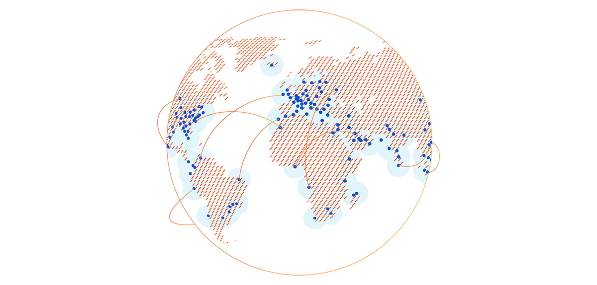
Global companies have enough of a challenge managing widely distributed corporate networks, let alone the additional geographic dispersity introduced as users are enabled to work from home or from anywhere. Because Cloudflare has data centers close to Internet users around the world, all traffic can be processed close to its source (your users), regardless of their location. This delivers performance benefits across all of our products.
We built our network to meet users where they are. Today, we have data centers in over 200 cities and over 100 countries. As the geographical reach of Cloudflare’s network has expanded, so has our capacity, which currently tops 42 Tbps. This reach and capacity is extended to your enterprise with Cloudflare One.
The same Cloudflare, everywhere
Traditional solutions for securing enterprise networks often involve managing a plethora of regional providers with different capabilities. This means that traffic from two users in different parts of the world may be treated completely differently, for example, with respect to quality of DDoS attack detection. With Cloudflare One, you can manage security for your entire global network from one place, consolidating and standardizing control.
Capacity for the good & the bad
With 42 Tbps of network capacity, you can rest assured that Cloudflare can handle all of your traffic – the clean, legitimate traffic you want, and the malicious and attack traffic you don’t.
Scalability
Every product on every server
All of Cloudflare’s services are standardized across our entire network. Every service runs on every server, which means that traffic through all of the products you use can be processed close to its source, rather than being sent around to different locations for different services. This also means that as our network continues to grow, all products benefit: new data centers will automatically process traffic for every service you use.
For example, your users who connect to the Internet through Cloudflare Gateway in South America connect to one of our data centers in the region, rather than backhauling to another location. When those users need to reach an origin located on the other side of the world, we can also route them over our private backbone to get them there faster.
Commodity hardware, software-based functions
We built our network using commodity hardware, which allows us to scale quickly without relying on one single vendor or getting stuck in supply chain bottlenecks. And the services that process your traffic are software-based – no specialized, third-party hardware performing specific functions. This means that the development, maintenance, and support for the products you use all lives within Cloudflare, reducing the complexity of getting help when you need it.
This approach also lets us build efficiency into our network. We use that efficiency to serve customers on our free plan and deliver a more cost-effective platform to our larger customers.
Connectivity
Cloudflare interconnects with over 8,800 networks globally, including major ISPs, cloud services, and enterprises. Because we’ve built one of the most interconnected networks in the world, Cloudflare One can deliver a better experience for your users and applications, regardless of your network architecture or connectivity/transit vendors.
Broad interconnectivity with eyeball networks
Because of our CDN product (among others), being close to end users (“eyeballs”) has always been critical for our network. Now that more people than ever are working from home, eyeball → datacenter connectivity is more crucial than ever. We’ve spoken to customers who, since transitioning to a work-from-home model earlier this year, have had congestion issues with providers who are not well-connected with eyeball networks. With Cloudflare One, your employees can do their jobs from anywhere with Cloudflare smoothly keeping their traffic (and your infrastructure) secure.
Extensive presence in peering facilities
Earlier this year, we announced Cloudflare Network Interconnect (CNI), the ability for you to connect your network with Cloudflare’s via a secure physical or virtual connection. Using CNI means more secure, reliable traffic to your network through Cloudflare One. With our highly-connected network, there’s a good chance we’re colocated with your organization in at least one peering facility, making CNI setup a no-brainer. We’ve also partnered with five interconnect platforms to provide even more flexibility with virtual (software-defined layer 2) connections with Cloudflare. Finally, we peer with major cloud providers all over the world, providing even more flexibility for organizations at any stage of hybrid/cloud transition.
Making the Internet smarter
Traditional approaches to creating secure and reliable network connectivity involve relying on expensive MPLS links to provide point to point connection. Cloudflare is built from the ground-up on the Internet, relying on and improving the same Internet links that customers use today. We’ve built software and techniques that help us be smarter about how we use the Internet to deliver better performance and reliability to our customers. We’ve also built the Cloudflare Global Private Backbone to help us even further enhance our software and techniques to deliver even more performance and reliability where it’s needed the most.
This approach allows us to use the variety of connectivity options in our toolkit intelligently, building toward a more performant network than what we could accomplish with a traditional MPLS solution. And because we use transit from a wide variety of providers, chances are that whoever your ISP is, you already have high-quality connectivity to Cloudflare’s network.
Insight
Diverse traffic workload yields attack intelligence
We process all kinds of traffic thanks to our network’s reach and the diversity of our customer base. That scale gives us unique insight into the Internet. We can analyze trends and identify new types of attacks before they hit the mainstream, allowing us to better prepare and protect customers as the security landscape changes.
We also provide you with visibility into these network and threat intelligence insights with tools like Cloudflare Radar and Cloudflare One Intel. Earlier this week, we launched a feature to block DNS tunneling attempts. We analyze a tremendous number of DNS queries and have built a model of what they should look like. We use that model to block suspicious queries which might leak data from devices.
Unique network visibility enables Smart Routing
In addition to attacks and malicious traffic across our network, we’re paying attention to the state of the Internet. Visibility across carriers throughout the world allows us to identify congestion and automatically route traffic along the fastest and most reliable paths. Contrary to the experience delivered by traditional scrubbing providers, Magic Transit customers experience minimal latency and sometimes even performance improvements with Cloudflare in path, thanks to our extensive connectivity and transit diversity.
Argo Smart Routing, powered by our extensive network visibility, improves performance for web assets by 30% on average; we’re excited to bring these benefits to any traffic through Cloudflare One with Argo Smart Routing for Magic Transit (coming soon!).
What’s next?
Cloudflare’s network is the foundation of the value and vision for Cloudflare One. With Cloudflare One, you can put our network between the Internet and your entire enterprise, gaining the powerful benefits of our global reach, scalability, connectivity, and insight. All of the products we’ve launched this week, like everything we’ve built so far, benefit from the unique advantages of our network.
We’re excited to see these effects multiply as organizations adopt Cloudflare One to protect and accelerate all of their traffic. And we’re just getting started: we’re going to continue to expand our network, and the products that run on it, to deliver an even faster, more secure, more reliable experience across all of Cloudflare One.
Cloudflare recently shipped improved upload speeds across our network for clients using HTTP/2. This post describes our journey from troubleshooting an issue to fixing it and delivering faster upload speeds to the global Internet.
We launchedspeed.cloudflare.com in May 2020 to give our users insight into how well their networks perform. The test provides download, upload and latency tests. Soon after release, we received reports from a small number of users that sometimes upload speeds were underreported. Our investigation determined that it seemed to happen with end users that had high upload bandwidth available (several hundreds Mbps class cable modem or fiber service). Our speed tests are performed via browser JavaScript, and most browsers use HTTP/2 by default. We found that HTTP/2 upload speeds were sometimes much slower than HTTP/1.1 (assuming all TLS) when the user had high available upload bandwidth.
Upload speed is more important than ever, especially for people using home broadband connections. As many people have been forced to work from home they’re using their broadband connections differently than before. Prior to the pandemic broadband traffic was very asymmetric (you downloaded way more than you uploaded… think listening to music, or streaming a movie), but now we’re seeing an increase in uploading as people video conference from home or create content from their home office.
Initial Tests
User reports were focused on particularly fast home networks. I set up a dummynet network simulator to test upload speed in a controlled environment. I launched a linux VM running our code inside my Macbook Pro and set up a dummynet between the VM and Mac host. Measuring upload speed is simple – create a file and upload using curl to an endpoint which accepts a request body. I ran the same test 20 times and took a median upload speed (Mbps).
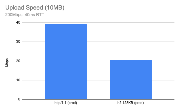
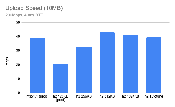
Stepping up to uploading a 10MB object over a network which has 200Mbps available bandwidth and 40ms RTT, the result was surprising. Using our production configuration, HTTP/2 upload speed tested at almost half of the same test conditions using HTTP/1.1 (higher is better).
The result may differ depending on your network, but the gap is bigger when the network is fast. On a slow network, like my home cable connection (5Mbps upload and 20ms RTT), HTTP/2 upload speed was almost identical to the performance observed with HTTP/1.1.
Receiver Flow Control
Before we get into more detail on this topic, my intuition suggested the issue was related to receiver flow control. Usually the client (browser or any HTTP client) is the receiver of data, but in the case the client is uploading content to the server, the server is the receiver of data. And the receiver needs some type of flow control of the receive buffer.
How we handle receiver flow control differs between HTTP/1.1 and HTTP/2. For example, HTTP/1.1 doesn’t define protocol-level receiver flow control since there is no multiplexing of requests in the connection and it’s up to the TCP layer which handles receiving data. Note that most of the modern OS TCP stacks have auto tuning of the receive buffer (we will revisit that later) and they tune based on the current BDP (bandwidth-delay product).
In the case of HTTP/2, there is a stream-level flow control mechanism because the protocol supports multiplexing of streams. Each HTTP/2 stream has its own flow control window and there is connection level flow control for all streams in the connection. If it’s too tight, the sender will be blocked by the flow control. If it’s too loose we may end up wasting memory for buffering. So keeping it optimal is important when implementing flow control and the most optimal strategy is to keep the receive buffer matching the current BDP. BDP represents the maximum bytes in flight in the given network and can be used as an optimal buffer size.
How NGINX handles the request body buffer
Initially I tried to find a parameter which controls NGINX upload buffering and tried to see if tuning the values improved the result. There are a couple of parameters which are related to uploading a request body.
Cloudflare does not use the proxy_buffering directive, so it can be immediately discounted. client_body_buffer_size is the size of the request body buffer which is used regardless of the protocol, so this one applies to HTTP/1.1 and HTTP/2 as well.
When looking into the code, here is how it works:
HTTP/1.1: use client_body_buffer_size buffer as a buffer between upstream and the client, simply repeating reading and writing using this buffer.
HTTP/2: since we need a flow control window update for the HTTP/2 DATA frame, there are two parameters:
http2_body_preread_size: it specifies the size of the initial request body read before it starts to send to the upstream.
client_body_buffer_size: it specifies the size of the request body buffer.
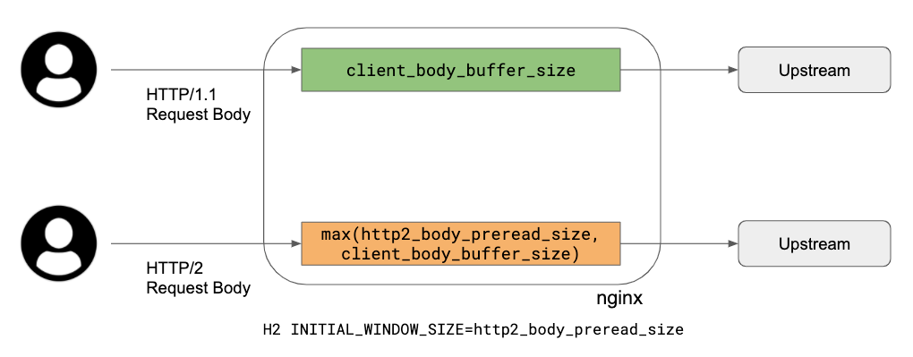
Those two parameters are used for allocating a request body buffer during uploading. Here is a brief summary of how unbuffered upload works:
Allocate a single request body buffer which size is a maximum of http2_body_preread_size and client_body_buffer_size. This means if http2_body_preread_size is 64KB and client_body_buffer_size is 128KB, then a 128KB buffer is allocated. We use 128KB for client_body_buffer_size.
HTTP/2 Settings INITIAL_WINDOW_SIZE of the stream is set to http2_body_preread_size and we use 64KB as a default (the RFC7540 default value).
HTTP/2 module reads up to http2_body_preread_size before sending it to upstream.
After flushing the preread buffer, keep reading from the client and write to upstream and send WINDOW_UPDATE frame back to the client when necessary until the request body is fully received.
To summarise what this means: HTTP/1.1 simply uses a single buffer, so TCP socket buffers do the flow control. However with HTTP/2, the application layer also has receiver flow control and NGINX uses a fixed size buffer for the receiver. This limits upload speed when the current link has a BDP larger than the current request body buffer size. So the bottleneck is HTTP/2 flow control when the buffer size is too tight.
We’re going to need a bigger buffer?
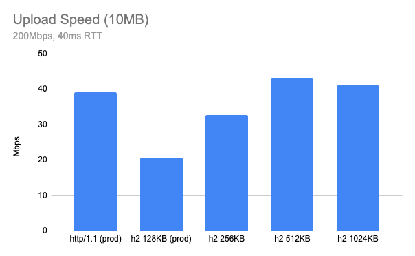
In theory, bigger buffer sizes should avoid upload bottlenecks, so I tried a few out by running my tests again. The previous chart result is now labelled “prod” and plotted alongside HTTP/2 tests with client_body_buffer_size set to 256KB, 512KB and 1024KB:
It appears 512KB is an optimal value for client_body_buffer_size.
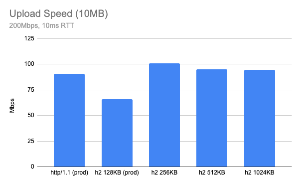
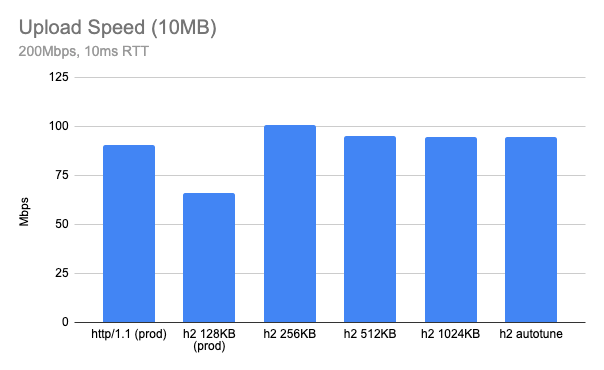
What if I test with some other network parameter? Here is when RTT is 10ms, in this case, 256KB looks optimal.
Both cases look much better than current 128KB and get a similar performance to HTTP/1.1 or even better. However, it seems like the optimal buffer size is a moving target and furthermore having too large a buffer size can hurt the performance: we need a smart way to find the optimal buffer size.
Autotuning request body buffer size
One of the ideas that can help this kind of situation is autotuning. For example, modern TCP stacks autotune their receive buffers automatically. In production, our edge also has TCP receiver buffer autotuning enabled by default.
net.ipv4.tcp_moderate_rcvbuf = 1
But in case of HTTP/2, TCP buffer autotuning is not very effective because the HTTP/2 layer is doing its own flow control and the existing 128KB was too small for a high BDP link. At this point, I decided to pursue autotuning HTTP/2 receive buffer sizing as well, similar to what TCP does.
The basic idea is that NGINX doubles the size of HTTP/2 request body buffer size based on its BDP. Here is an algorithm currently implemented in our version of NGINX:
Allocate a request body buffer as explained above.
For every RTT (using linux tcp_info), update the current BDP.
Double the request body buffer size when the current BDP > (receiver window / 4).
Test Result
Lab Test
Here is a test result when HTTP/2 autotune upload is enabled (still using client_body_buffer_size 128KB). You can see “h2 autotune” is doing pretty well – similar or even slightly faster than HTTP/1.1 speed (that’s the initial goal). It might be slightly worse than a hand-picked optimal buffer size for given conditions, but you can see now NGINX picks up optimal buffer size automatically based on network conditions.
Production test
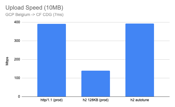
After we deployed this feature, I ran similar tests against our production edge, uploading a 10MB file from well connected client nodes to our edge. I created a Linux VM instance in Google Cloud and ran the upload test where the network is very fast (a few Gbps) and low latency (<10ms).
Here is when I run the test in the Google Cloud Belgium region to our CDG (Paris) PoP which has 7ms RTT. This looks very good with almost 3x improvement.
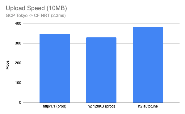
I also tested between the Google Cloud Tokyo region and our NRT (Tokyo) PoP, which had a 2.3ms RTT. Although this is not realistic for home users, the results are interesting. A 128KB fixed buffer performs well, but HTTP/2 with buffer autotune outperforms even HTTP/1.1.
Summary
HTTP/2 upload buffer autotuning is now fully deployed in the Cloudflare edge. Customers should now benefit from improved upload performance for all HTTP/2 connections, including speed tests on speed.cloudflare.com. Autotuning upload buffer size logic works well for most cases, and now HTTP/2 upload is much faster than before! When we think about the performance we usually tend to think about download speed or latency reduction, but faster uploading can also help users working from home when they need a large amount of upload, such as photo/video sharing apps, content creation, video conferencing or self broadcasting.
To provide the best experiences, we use technologies like cookies to store and/or access device information. Consenting to these technologies will allow us to process data such as browsing behavior or unique IDs on this site. Not consenting or withdrawing consent, may adversely affect certain features and functions.
Functional
Always active
The technical storage or access is strictly necessary for the legitimate purpose of enabling the use of a specific service explicitly requested by the subscriber or user, or for the sole purpose of carrying out the transmission of a communication over an electronic communications network.
Preferences
The technical storage or access is necessary for the legitimate purpose of storing preferences that are not requested by the subscriber or user.
Statistics
The technical storage or access that is used exclusively for statistical purposes.The technical storage or access that is used exclusively for anonymous statistical purposes. Without a subpoena, voluntary compliance on the part of your Internet Service Provider, or additional records from a third party, information stored or retrieved for this purpose alone cannot usually be used to identify you.
Marketing
The technical storage or access is required to create user profiles to send advertising, or to track the user on a website or across several websites for similar marketing purposes.