Tag Archives: Scaling

Mount Mayhem at Netflix: Scaling Containers on Modern CPUs

Post Syndicated from Netflix Technology Blog original https://netflixtechblog.com/mount-mayhem-at-netflix-scaling-containers-on-modern-cpus-f3b09b68beac

Authors: Harshad Sane, Andrew Halaney

Imagine this — you click play on Netflix on a Friday night and behind the scenes hundreds of containers spring to action in a few seconds to answer your call. At Netflix, scaling containers efficiently is critical to delivering a seamless streaming experience to millions of members worldwide. To keep up with responsiveness at this scale, we modernized our container runtime, only to hit a surprising bottleneck: the CPU architecture itself.

Let us walk you through the story of how we diagnosed the problem and what we learned about scaling containers at the hardware level.

The Problem

When application demand requires that we scale up our servers, we get a new instance from AWS. To use this new capacity efficiently, pods are assigned to the node until its resources are considered fully allocated. A node can go from no applications running to being maxed out within moments of being ready to receive these applications.

As we migrated more and more from our old container platform to our new container platform, we started seeing some concerning trends. Some nodes were stalling for long periods of time, with a simple health check timing out after 30 seconds. An initial investigation showed that the mount table length was increasing dramatically in these situations, and reading it alone could take upwards of 30 seconds. Looking at systemd’s stack it was clear that it was busy processing these mount events as well and could lead to complete system lockup. Kubelet also timed out frequently talking to containerd in this period. Examining the mount table made it clear that these mounts were related to container creation.

The affected nodes were almost all r5.metal instances, and were starting applications whose container image contained many layers (50+).

Challenge

Mount Lock Contention

The flamegraph in Figure 1 clearly shows where containerd spent its time. Almost all of the time is spent trying to grab a kernel-level lock as part of the various mount-related activities when assembling the container’s root filesystem!
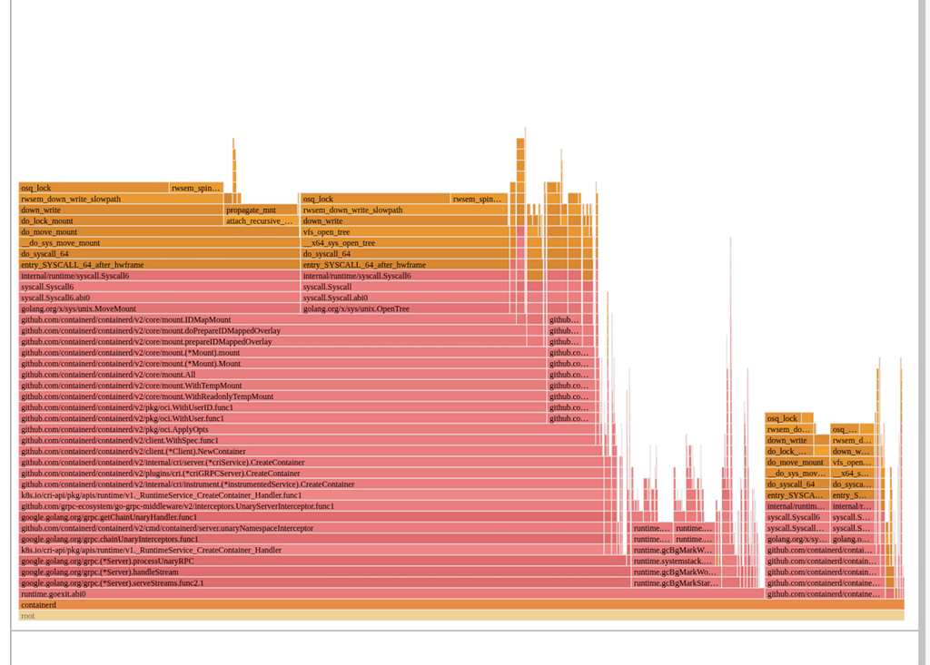
Figure 1: Flamegraph depicting lock contention

Looking closer, containerd executes the following calls for each layer if using user namespaces:

  1. open_tree() to get a reference to the layer / directory
  2. mount_setattr() to set the idmap to match the container’s user range, shifting the ownership so this container can access the files
  3. move_mount() to create a bind mount on the host with this new idmap applied

These bind mounts are owned by the container’s user range and are then used as the lowerdirs to create the overlayfs-based rootfs for the container. Once the overlayfs rootfs is mounted, the bind mounts are then unmounted since they are not necessary to keep around once the overlayfs is constructed.

If a node is starting many containers at once, every CPU ends up busy trying to execute these mounts and umounts. The kernel VFS has various global locks related to the mount table, and each of these mounts requires taking that lock as we can see in the top of the flamegraph. Any system trying to quickly set up many containers is prone to this, and this is a function of the number of layers in the container image.

For example, assume a node is starting 100 containers, each with 50 layers in its image. Each container will need 50 bind mounts to do the idmap for each layer. The container’s overlayfs mount will be created using those bind mounts as the lower directories, and then all 50 bind mounts can be cleaned up via umount. Containerd actually goes through this process twice, once to determine some user information in the image and once to create the actual rootfs. This means the total number of mount operations on the start up path for our 100 containers is 100 * 2 * (1 + 50 + 50) = 20200 mounts, all of which require grabbing various global mount related locks!

Diagnosis

What’s Different In The New Runtime?

As alluded to in the introduction, Netflix has been undergoing a modernization of its container runtime. In the past a virtual kubelet + docker solution was used, whereas now a kubelet + containerd solution is being used. Both the old runtime and the new runtime used user namespaces, so what’s the difference here?

  1. Old Runtime:
    All containers shared a single host user range. UIDs in image layers were shifted at untar time, so file permissions matched when containers accessed files. This worked because all containers used the same host user.
  2. New Runtime:
    Each container gets a unique host user range, improving security — if a container escapes, it can only affect its own files. To avoid the costly process of untarring and shifting UIDs for every container, the new runtime uses the kernel’s idmap feature. This allows efficient UID mapping per container without copying or changing file ownership, which is why containerd performs many mounts.

Figure 2 below is a simplified example of how this idmap feature looks like:

Figure 2: idmap feature

Why Does Instance Type Matter?

As noted earlier, the issue was predominantly occurring on r5.metal instances. Once we identified the root issue we could easily reproduce by creating a container image with many layers and sending hundreds of workloads using the image to a test node.

To better understand why this bottleneck was more profound on some instances compared to others, we benchmarked container launches on different AWS instance types:

  • r5.metal (5th gen Intel, dual-socket, multiple NUMA domains)
  • m7i.metal-24xl (7th gen Intel, single-socket, single NUMA domain)
  • m7a.24xlarge (7th gen AMD, single-socket, single NUMA domain)

Baseline Results

Figure 3 shows the baseline results from scaling containers on each instance type
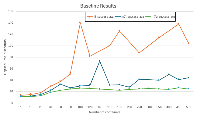
  • At low concurrency (≤ ~20 containers), all platforms performed similarly
  • As concurrency increased, r5.metal began to fail around 100 containers
  • 7th generation AWS instances maintained lower launch times and higher success rates as concurrency grew
  • m7a instances showed the most consistent scaling behavior with the lowest failure rates even at high concurrency

Deep Dive

Using perf record and custom microbenchmarks, we can see the hottest code path was in the Linux kernel’s Virtual Filesystem (VFS) path lookup code — specifically, a tight spin loop waiting on a sequence lock in path_init(). The CPU spent most of its time executing the pause instruction, indicating many threads were spinning, waiting for the global lock, as shown in the disassembly snippet below

path_init():

mov mount_lock,%eax
test $0x1,%al
je 7c
pause

Using Intel’s Topdown Microarchitecture Analysis (TMA), we observed:

  • 95.5% of pipeline slots were stalled on contested accesses (tma_contested_accesses).
  • 57% of slots were due to false sharing (multiple cores accessing the same cache line).
  • Cache line bouncing and lock contention were the primary culprits.

Given a high amount of time being spent in contested accesses, the natural thinking from a perspective of hardware variations led to investigation of NUMA and Hyperthreading impact coming from the architecture to this subset

NUMA Effects

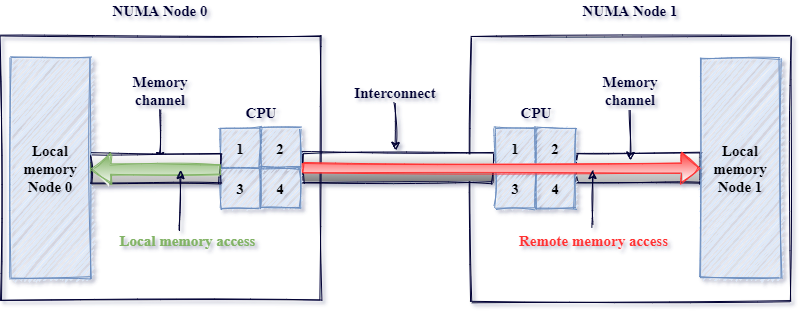
Non-Uniform Memory Access (NUMA) is a system design where each processor has its own local memory for faster access but relies on an interconnect to access the memory attached to a remote processor. Introduced in the 1990s to improve scalability in multiprocessor systems, NUMA boosts performance but also introduces higher latency when a CPU needs to access memory attached to another processor. Figure 4 is a simple image describing local vs remote access patterns of a NUMA architecture
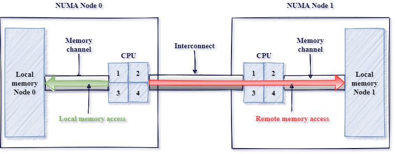
Figure 4: Source: https://pmem.io/images/posts/numa_overview.png

AWS instances come in a variety of shapes and sizes. To obtain the largest core count, we tested the 2-socket 5th generation metal instances (r5.metal), on which containers were orchestrated by the titus agent. Modern dual-socket architectures implement NUMA design, leading to faster local but higher remote access latencies. Although container orchestration can maintain locality, global locks can easily run into high latency effects due to remote synchronization. In order to test the impact of NUMA, we tested an AWS 48xl sized instance with 2 NUMA nodes or sockets versus an AWS 24xl sized instance, which represents a single NUMA node or socket. As seen from Figure 5, the extra hop introduces high latencies and hence failures very quickly.
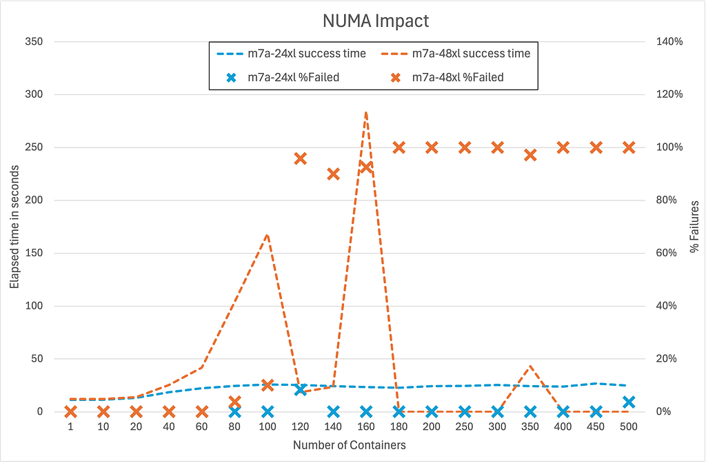
Figure 5: Numa Impact

Hyperthreading Effects

  • Hyperthreading (HT): Disabling HT on m7i.metal-24xl (Intel) improved container launch latencies by 20–30% as seen in Figure 6, since hyperthreads compete for shared execution resources, worsening the lock contention. When hyperthreading is enabled, each physical CPU core is split into two logical CPUs (hyperthreads) that share most of the core’s execution resources, such as caches, execution units, and memory bandwidth. While this can improve throughput for workloads that are not fully utilizing the core, it introduces significant challenges for workloads that rely heavily on global locks. By disabling hyperthreading, each thread runs on its own physical core, eliminating this competition for shared resources between hyperthreads. As a result, threads can acquire and release global locks more quickly, reducing overall contention and improving latency for operations that generally share underlying resources.
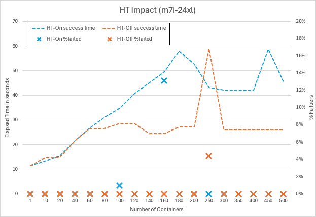
Figure 6: Hyperthreading impact

Why Does Hardware Architecture Matter?

Centralized Cache Architectures

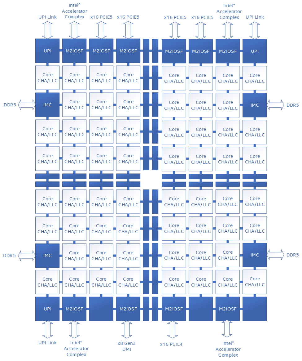
Some modern server CPUs use a mesh-style interconnect to link cores and cache slices, with each intersection managing cache coherence for a subset of memory addresses. In these designs, all communication passes through a central queueing structure, which can only handle one request for a given address at a time. When a global lock (like the mount lock) is under heavy contention, all atomic operations targeting that lock are funneled through this single queue, causing requests to pile up and resulting in memory stalls and latency spikes.

In some well-known mesh-based architectures as shown in Figure 7 below, this central queue is called the “Table of Requests” (TOR), and it can become a surprising bottleneck when many threads are fighting for the same lock. If you’ve ever wondered why certain CPUs seem to “pause for breath” under heavy contention, this is often the culprit.
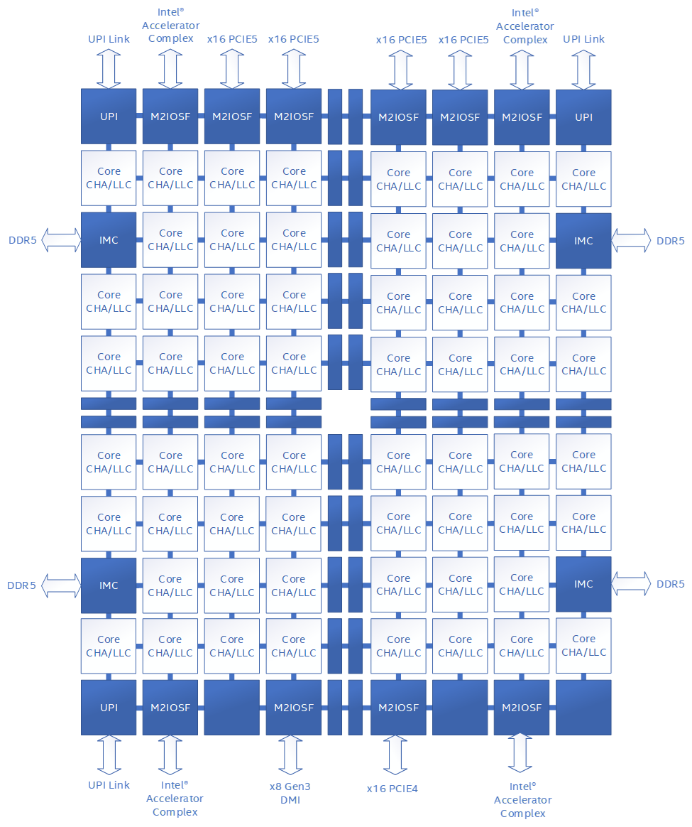
Figure 7: Public document from one of the major CPU vendors Source:https://www.intel.com/content/dam/developer/articles/technical/ddio-analysis-performance-monitoring/Figure1.png

Distributed Cache Architectures

Some modern server CPUs use a distributed, chiplet-based architecture (Figure 8), where multiple core complexes, each with their own local last-level cache — are connected via a high-speed interconnect fabric. In these designs, cache coherence is managed within each core complex, and traffic between complexes is handled by a scalable control fabric. Unlike mesh-based architectures with centralized queueing structures, this distributed approach spreads contention across multiple domains, making severe stalls from global lock contention less likely. For those interested in the technical details, public documentation from major CPU vendors provides deeper insight into these distributed cache and chiplet designs.
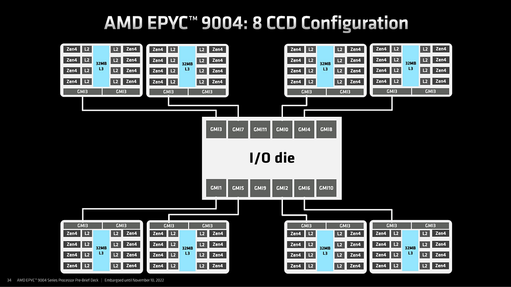
Figure 8: Public document from one of the major CPU vendors, Source: (AMD EPYC 9004 Genoa Chiplet Architecture 8x CCD — ServeTheHome)

Here is a comparison of the same workload run on m7i (centralized cache architecture) vs m7a (distributed cache architecture). Note that, in order to make it closely comparable, Hyperthreading (HT) was disabled on m7i, given previous regression seen in Figure 6, and experiments were run using same core counts. The result clearly shows a fairly consistent difference in performance of approximately 20% as shown in Figure 9
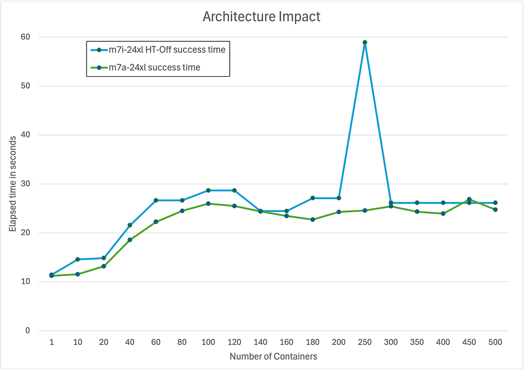
Figure 9: Architectural impact between m7i and m7a

Microbenchmark Results

To prove the above theory related to NUMA, HT and micro-architecture, we developed a small microbenchmark which basically invokes a given number of threads that then spins on a globally contended lock. Running the benchmark at increasing thread counts reveals the latency characteristics of the system under different scenarios. For example, Figure 10 below is the microbenchmark results with NUMA, HT and different microarchitectures.

Figure 10: Global lock contention benchmark results

Results from this custom synthetic benchmark (pause_bench) confirmed:

  • On r5.metal, eliminating NUMA by only using a single socket significantly drops latency at high thread counts
  • On m7i.metal-24xl, disabling hyperthreading further improves scaling
  • On m7a.24xlarge, performance scales the best, demonstrating that a distributed cache architecture handles cache-line contention in this case of global locks more gracefully.

Improving Software Architecture

While understanding the impacts of the hardware architecture is important for assessing possible mitigations, the root cause here is contention over a global lock. Working with containerd upstream we came to two possible solutions:

  1. Use the newer kernel mount API’s fsconfig() lowerdir+ support to supply the idmap’ed lowerdirs as fd’s instead of filesystem paths. This avoids the move_mount() syscall mentioned prior which requires global locks to mount each layer to the mount table
  2. Map the common parent directory of all the layers. This makes the number of mount operations go from O(n) to O(1) per container, where n is the number of layers in the image

Since using the newer API requires using a new kernel, we opted to make the latter change to benefit more of the community. With that in place, no longer do we see containerd’s flamegraph being dominated by mount-related operations. In fact, as seen in Figure 11 below we had to highlight them in purple below to see them at all!
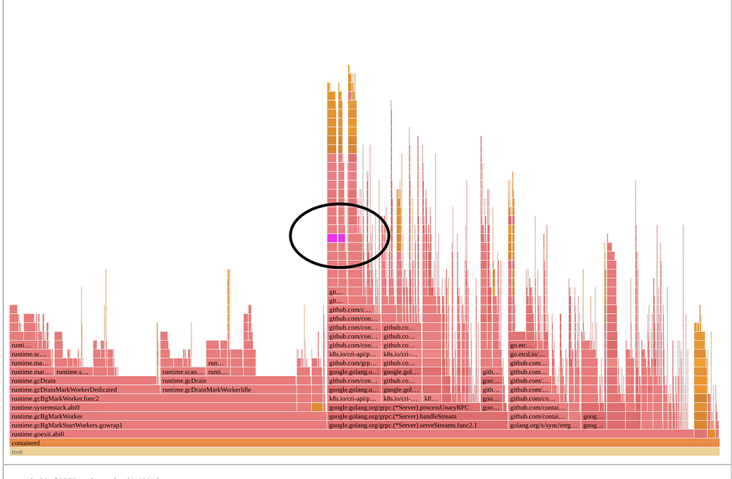
Figure 11: Optimized solution

Conclusion

Our journey migrating to a modern kubelet + containerd runtime at Netflix revealed just how deeply intertwined software and hardware architecture can be when operating at scale. While kubelet/containerd’s usage of unique container users brought significant security gains, it also surfaced new bottlenecks rooted in kernel and CPU architecture — particularly when launching hundreds of many layered container images in parallel. Our investigation highlighted that not all hardware is created equal for this workload: centralized cache management amplified cache contention while distributed cache design smoothly scaled under load.

Ultimately, the best solution combined hardware awareness with software improvements. For an immediate mitigation we chose to route these workloads to CPU architectures that scaled better under these conditions. By changing the software design to minimize per-layer mount operations, we eliminated the global lock as a launch-time bottleneck — unlocking faster, more reliable scaling regardless of the underlying CPU architecture. This experience underscores the importance of holistic performance engineering: understanding and optimizing both the software stack and the hardware it runs on is key to delivering seamless user experiences at Netflix scale.

We trust these insights will assist others in navigating the evolving container ecosystem, transforming potential challenges into opportunities for building robust, high-performance platforms.

Special thanks to the Titus and Performance Engineering teams at Netflix.


Mount Mayhem at Netflix: Scaling Containers on Modern CPUs was originally published in Netflix TechBlog on Medium, where people are continuing the conversation by highlighting and responding to this story.
Managing dynamic marketplace content at scale: Grab’s approach to content moderation

Post Syndicated from Grab Tech original https://engineering.grab.com/dynamic-marketplace

In the fast-paced world of on-demand delivery, maintaining safe marketplaces is a complex undertaking. Grab, a leading superapp in Southeast Asia, operates GrabFood and GrabMart, two popular marketplaces that connect consumers with a wide range of food and daily necessities. With more than 100k listings for different items updated daily by our merchants across eight different countries, Grab is rising to the challenge of ensuring that its marketplaces remain compliant with its own policies, government regulations as well as platform policies.

This article provides an overview of how Grab employs a combination of automated and manual content moderation to manage its dynamic marketplace content efficiently, while also collaborating with Google to ensure marketplace safety. Stay tuned for future articles that will delve deeper into the technology and solutions used for content moderation.

Dynamic Marketplace Landscape

Marketplaces like GrabFood and GrabMart are at the forefront of connecting merchants and consumers. These marketplaces provide an avenue for merchants to showcase their offerings, enabling consumers to conveniently access a plethora of on-demand options. However, in an environment characterized by rapid changes as well as evolving regulatory frameworks, maintaining the integrity of these marketplaces becomes a formidable task.

Scale and Flexibility: A Dual Challenge

The cornerstone of Grab’s success lies in its ability to adapt to the unique regulations and requirements of each country it operates in. This necessitates a nuanced and multifaceted approach to content moderation. To achieve both scale and flexibility, Grab employs a proactive strategy that combines and leverages automated and manual moderation processes.

Automated Moderation

Automated moderation plays a pivotal role in efficiently managing the high volume of listings that undergo daily updates. Grab utilises advanced algorithms and machine learning technologies, built in-house, to scan listings everyday for potential violations of its own policies, government regulations and platform policies. This automation not only speeds up the process to put eligible listings on the Grab platform, but also ensures consistent adherence to predefined guidelines. However, automated moderation is not without its limitations, as contextual understanding and subjective judgment often require human intervention.

Manual Moderation

Recognising the nuanced nature of content moderation, Grab employs a team of human moderators who possess the cultural awareness and contextual understanding necessary to assess complex cases. These moderators review listings flagged by algorithms and machine learning technologies that require human judgment, ensuring that content aligns with Grab’s policies, local regulations as well as platform policies. Manual moderation adds a layer of human insight that automated systems may lack, contributing to a more accurate and contextually sensitive approach.

In its commitment to ensuring marketplace safety, Grab has also established a strong collaboration with Google. Grab works hand in hand with Google to collectively ensure adherence to Play Store policies and guidelines.

Grab

  • Programme Management: Poonam Gambhire, Shuyang Sun
  • Product: Chris Collard
  • Engineering: Shuya Ding, Kirubakaran Duraisamy, Xu Chen

Google

  • Play Policy: Siddhartha Paul Tiwari
  • Business Development: Mika Igarashi

Join us

Grab is the leading superapp platform in Southeast Asia, providing everyday services that matter to consumers. More than just a ride-hailing and food delivery app, Grab offers a wide range of on-demand services in the region, including mobility, food, package and grocery delivery services, mobile payments, and financial services across 428 cities in eight countries.

Powered by technology and driven by heart, our mission is to drive Southeast Asia forward by creating economic empowerment for everyone. If this mission speaks to you, join our team today!

How to automate AWS Managed Microsoft AD scaling based on utilization metrics

Post Syndicated from Dennis Rothmel original https://aws.amazon.com/blogs/security/how-to-automate-aws-managed-microsoft-ad-scaling-based-on-utilization-metrics/

AWS Directory Service for Microsoft Active Directory (AWS Managed Microsoft AD), provides a fully managed service for Microsoft Active Directory (AD) in the AWS cloud. When you create your directory, AWS deploys two domain controllers in separate Availability Zones that are exclusively yours for high availability. For use cases requiring even higher resilience and performance, in a specific Region or during specific hours, AWS Managed Microsoft AD allows you to scale by deploying additional domain controllers to meet your needs. These domain controllers can help load-balance, increase overall performance, or simply provide additional nodes to protect against temporary availability issues. AWS Managed Microsoft AD allows you to define the correct number of domain controllers for your directory based on your individual use case.

This post will walk you through how to automate scaling in AWS Managed Microsoft AD using utilization metrics from your directory. You’ll do this using Amazon CloudWatch Alarms, SNS notifications, and a Lambda function to increase the number of domain controllers in your directory based on utilization peaks.

Simplified directory scaling

AWS Managed Microsoft AD has now simplified this directory scaling process by integrating with Amazon CloudWatch metrics. This new integration enables you to:

  1. Analyze your directory to identify expected average and peak directory utilization
  2. Scale your directory based on utilization data to adequately address the expected load
  3. Automate the addition of domain controllers to handle unexpected load.

Integration is available for both domain controller utilization metrics such as CPU, Memory, Disk and Network, and for AD-specific metrics, such as LDAP searches, binds, DNS queries, and Directory reads/writes. Analyzing this data over time to identify expected average and peak utilization on your directory can help you deploy additional domain controllers in Regions that need them. Once you’ve established this utilization baseline, you can deploy additional domain controllers to service this load, and configure alarms for anything exceeding this baseline.

Solution overview

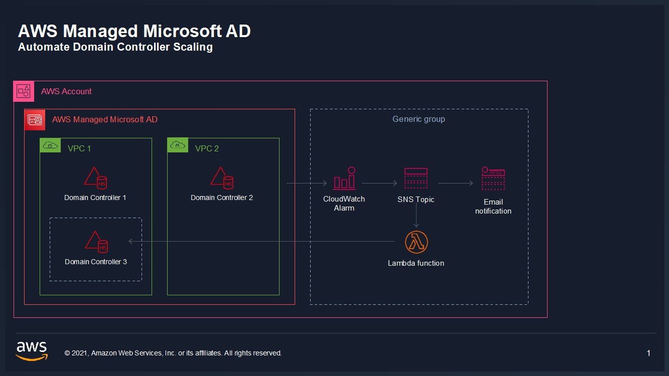
In this example, our AWS Managed Microsoft AD has the default two domain controllers; once your utilization threshold is reached, you’ll add one additional domain controller (domain controller 3 in the diagram) to cover this additional load. 

Figure 1: Solution overview

Figure 1: Solution overview

To create a CloudWatch Alarm with SNS topic notifications

  1. In the AWS Console, navigate to CloudWatch
  2. Choose Metrics to see the Browse Metrics panel
  3. Choose the Directory Service namespace, then choose AWS Managed Microsoft AD.
  4. In the Directory ID column, select your directory and check search for this only.
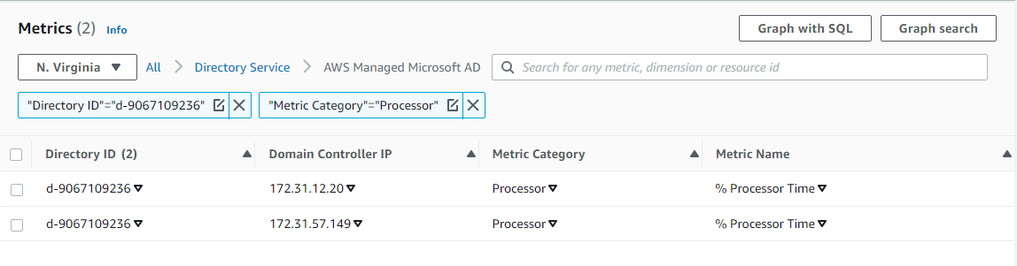
  5. From the Metric Category column, select Processor from Metric Category and check add to search. This view will show the processor utilization for your directory.
  6.  

    Figure 2. Processor utilization metrics

    Figure 2. Processor utilization metrics

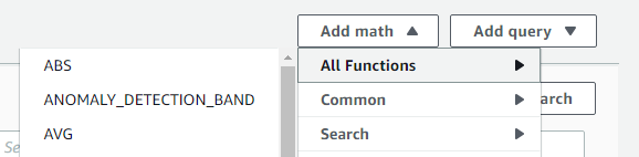
  7. To see the average utilization across all domain controllers, choose Add Math, then All Functions, then AVG to create a metric math expression for average CPU utilization across all domain controllers.
  8.  

    Figure 3. Adding a math function to compute average

    Figure 3. Adding a math function to compute average

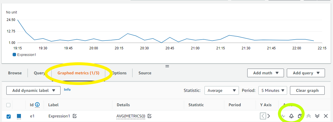
  9. Next, choose the Graphed Metrics tab in the CloudWatch metrics console, select the newly created expression, then select the bell icon from the Actions column to create a CloudWatch alarm based on this metric.
  10. Figure 4. Create a CloudWatch Alarm using Metric Math Expression

    Figure 4. Create a CloudWatch Alarm using Metric Math Expression

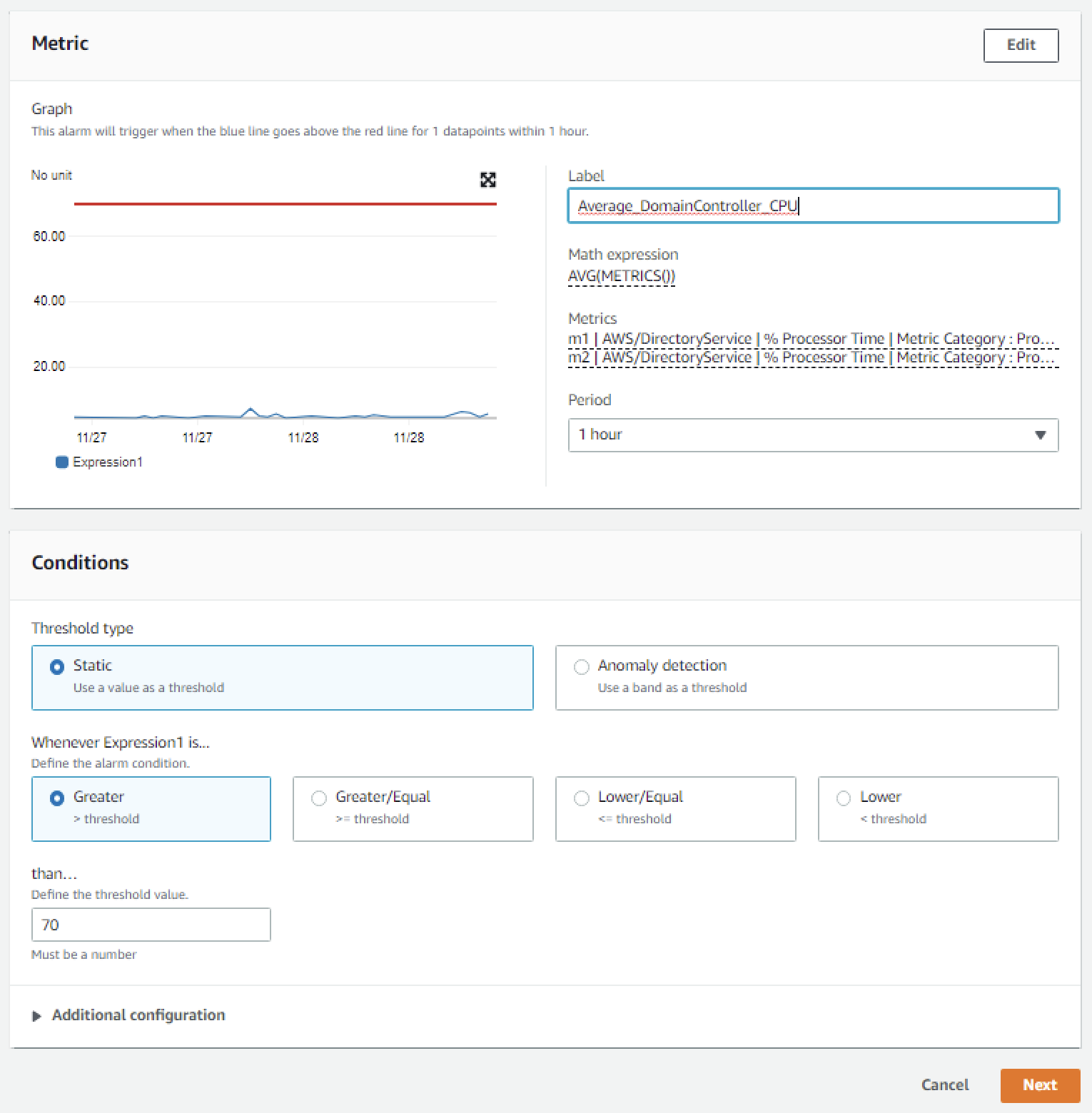
  11. Configure the threshold alarm to trigger when CPU utilization exceeds 70%.
  12.  In the Metrics section, under Period, choose 1 Hour.
     In the Conditions section, under Threshold Type, choose Static. Under Define the alarm condition, choose Greater than threshold. Under Define the threshold value, enter 70. See Figure 5 for an image of how alarm parameters should look on your screen. Choose Next to Configure actions

    Figure 5. Configure the alarm parameters

    Figure 5. Configure the alarm parameters

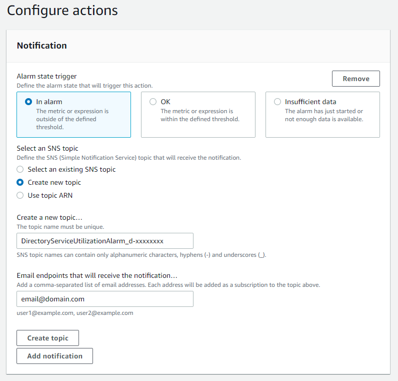
  13. On the Configure actions screen, configure the actions using the parameters listed below to send an email notification when the alarm state is triggered. See Figure 6 for an image of how email notifications are configured.
  14.   In the Notification section, set Alarm state trigger to In alarm.   Set Select an SNS topic to Create topic.  Fill in the name of the alarm in the Create a new topic field, and add the email where notifications should be sent to the Email endpoints that will receive notification field. An email address is required to create the SNS topic and you should use an email address that’s accessible by your operations team. This SNS topic will be used to trigger the Lambda automation described in a later section. Note: make a note of the SNS topic name you chose; you will use it later when creating the Lambda function in the To create an AWS Lambda function to automate scale out procedure below. 

    Figure 6. Create SNS topic and email notification

    Figure 6. Create SNS topic and email notification

  15. In the Alarm name field, provide a name for the alarm. You can optionally also add an Alarm description. Choose Next.
  16. Review your configuration, and choose Create alarm to create the alarm.

Once you’ve completed these steps, you will now have an alarm implemented for when domain controller CPU utilization exceeds an average of 70% across both domain controllers. This will trigger an SNS topic when your directory is experiencing a heavy load, which will be used to start the Lambda automation and will send an informational email notification. In the next section, we’ll configure an AWS Lambda function to automate the addition of a domain controller based on this SNS topic.

For additional details on CloudWatch Alarms, please see the Amazon CloudWatch documentation.

To create an AWS Lambda function to automate scale out

The sample Lambda function shown below checks the number of domain controllers in this Region, and increases that by adding one additional domain controller. This procedure describes how to configure the IAM role required for this Lambda function, then how to deploy the Lambda function to execute when the alarm is triggered to automatically add a domain controller when your load exceeds your typical usage baseline.

Note: For additional details on Lambda creation, please see the AWS Lambda documentation.

To automate scale-out using AWS Lambda

  1. In the AWS Console, navigate to IAM and choose Policies, then choose Create Policy.
  2. Choose the JSON tab, and create a new IAM role using the policy provided in JSON below.
  3. For more details on this configuration, see the AWS Directory Service documentation.

    Sample policy


    {
    	"Version":"2012-10-17",
    	"Statement":[
    	{
    		"Effect":"Allow",
    		"Action":[
    			"ds:DescribeDomainControllers",
    			"ds:UpdateNumberOfDomainControllers",
    			"ec2:DescribeSubnets",
    			"ec2:DescribeVpcs",
    			"ec2:CreateNetworkInterface",
    			"ec2:DescribeNetworkInterfaces",
    			"ec2:DeleteNetworkInterface"
    		],
    		"Resource":"*"
    	}
    	]
    }
    

  4. Choose Next:Tags to add tags (optional) before choosing Next:Review.
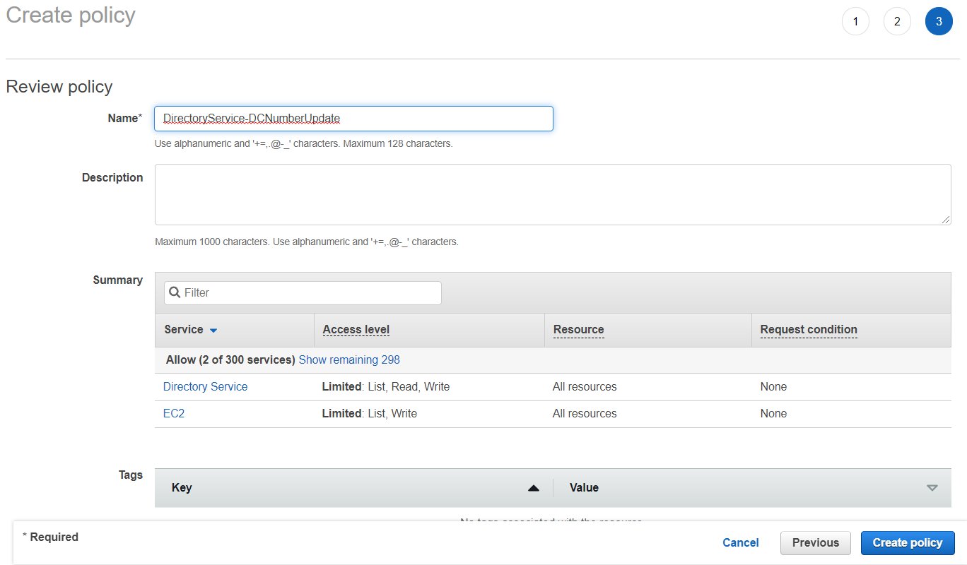
  5. On the Create Policy screen, provide a name in the Name field. You can optionally also add a description. Choose Create policy to complete creating the new policy.
  6.  
    Note: make a note of the policy name you chose; you will use it later when updating the execution role for the Lambda function.  

    Figure 7. Provide a name to create the IAM policy

    Figure 7. Provide a name to create the IAM policy

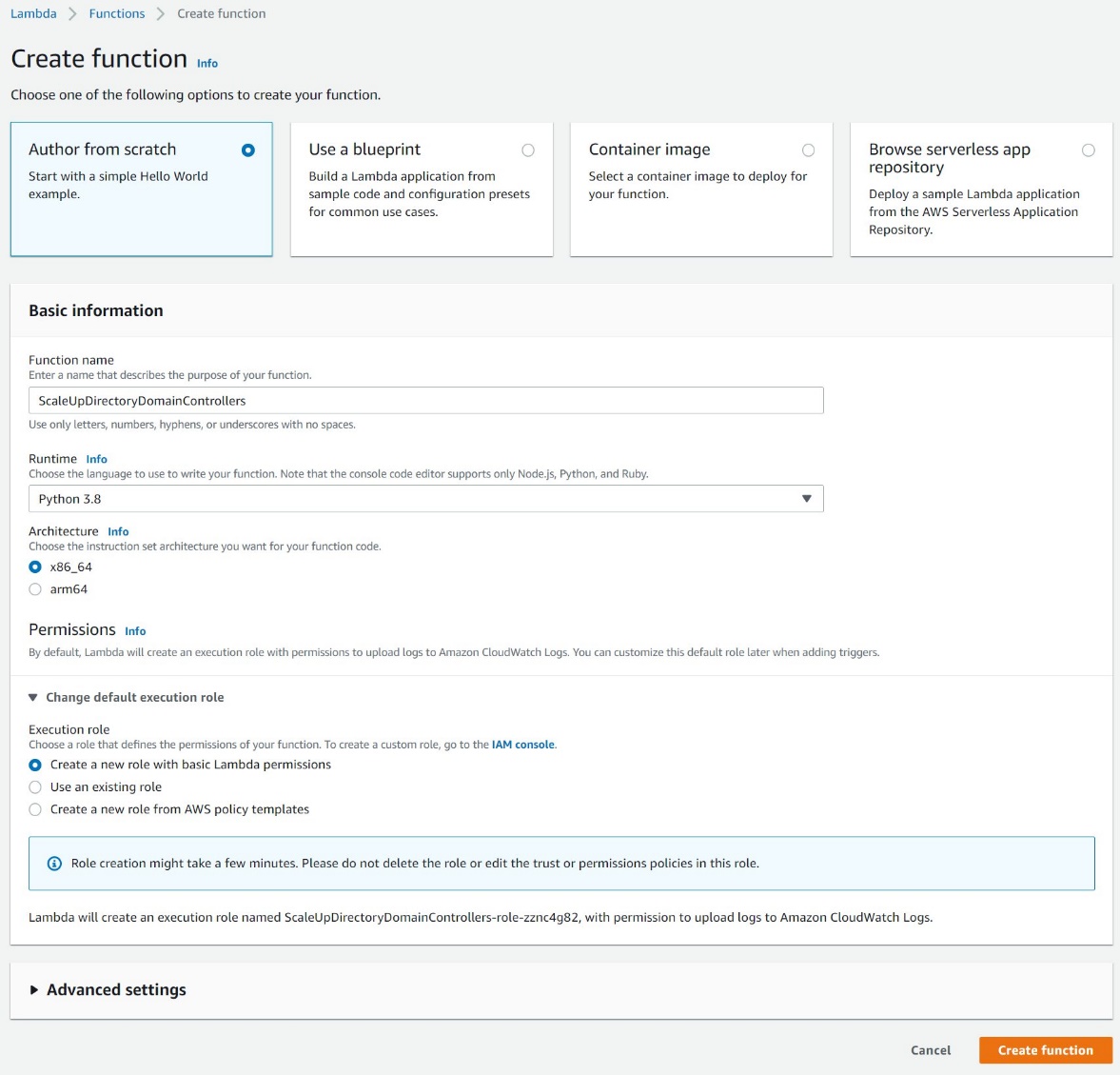
  7. In the AWS Console, navigate to Lambda and choose Create Function
  8. On the Create Function screen, select Author from Scratch and provide a Name, then choose Create Function.
  9. Figure 8. Create a Lambda function

    Figure 8. Create a Lambda function

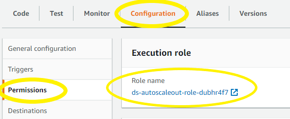
  10. Once created, on the Lambda function’s page, choose the Configuration tab, then choose Permissions from the sidebar and choose the execution role name linked under Role name. This will open the IAM console in another tab, preloaded to your Lambda execution role.
  11.  

    Figure 9: Select the Execution Role

    Figure 9: Select the Execution Role

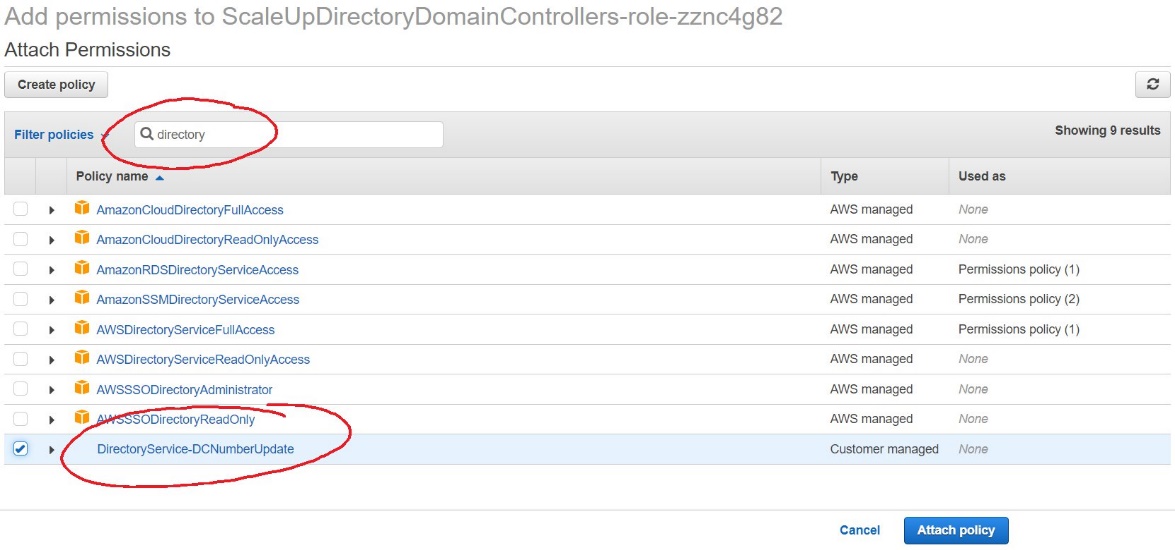
  12. On the execution role screen, choose Attach policies and select the IAM policy you’ve just created (e.g. DirectoryService-DCNumber Update). On the Attach Permissions screen, choose Attach policy to complete updating the execution role. Once completed this step, you may close this tab and return the previous browser tab.
  13.  

    Figure 10. Select and attach the IAM policy

    Figure 10. Select and attach the IAM policy

  14. On the Lambda function screen, choose the Configuration tab, then choose Triggers from the sidebar.
  15. On the Add Trigger screen, choose the pulldown under Trigger configuration and select SNS. On the SNS topic box, select the SNS topic you created in Step 9 of the To create a CloudWatch Alarm with SNS topic notifications procedure above. Then choose Add to complete the trigger configuration.
  16. On the Lambda function screen, choose the Configuration tab, then choose Environment variables from the sidebar.
  17. On the Environment variables card, click Edit.
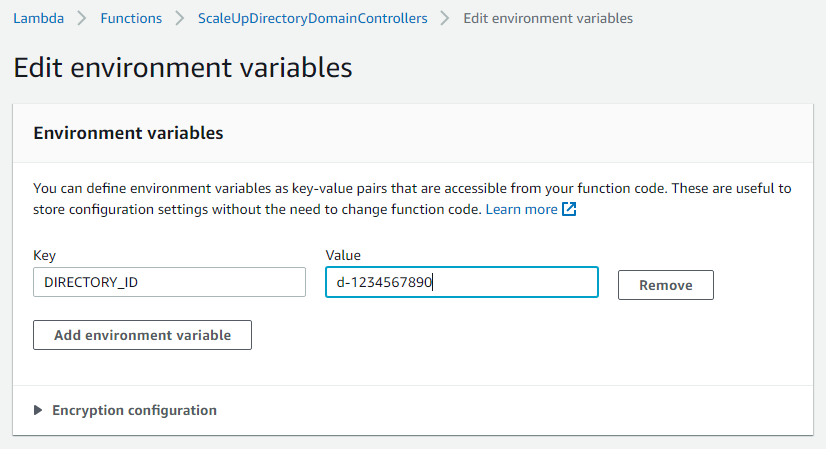
  18. On the Edit environment variables screen, choose Add environment variables and use the Key “DIRECTORY_ID” and the Value will be the directory ID for you AWS Managed Microsoft AD.
  19.  

    Figure 11. The "Edit environment variables" screen

    Figure 11. The “Edit environment variables” screen

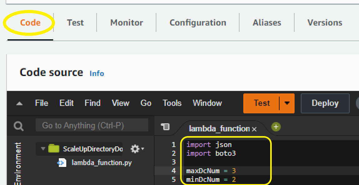
  20. On the Lambda function screen, choose the Code tab to open the in-browser code editor experience inside the Code source card. Paste in the sample Lambda function code given below to complete the implementation.
  21.  

    Figure 12. Paste sample code to complete the Lambda function setup

    Figure 12. Paste sample code to complete the Lambda function setup

Sample Lambda function code

The sample Lambda function given below automates adding another domain controller to your directory. When your CloudWatch alarm triggers, you will receive a notification email, and an additional domain controller will be deployed to provide the added capacity to support the increase in directory usage.

Note: The example code contains a variable for the maximum number of domain controllers (maxDcNum), to prevent you from over provisioning in the event of a missed configuration. This value is set to 3 for this blog post’s example and can be increased to suit your use case. 

import json
import boto3

maxDcNum = 10
minDcNum = 2
region   = "us-east-1"
dsId = "d-906752246f"

ds = boto3.client('ds', region_name=region)

def lambda_handler(event, context):
    
    ## get the current number of domain controllers
    dcs = ds.describe_domain_controllers(DirectoryId = dsId)

    DomainControllers = dcs["DomainControllers"]
    
    DCcount = len(DomainControllers)
    print(">>> Current number of DCs:" + str(DCcount))

    #increase the number of DCs
    if DCcount < maxDcNum:
        NewDCnumber = DCcount + 1 
        response = ds.update_number_of_domain_controllers(DirectoryId = dsId, DesiredNumber =  NewDCnumber);    

        return {
            'statusCode': 200,
            'body': json.dumps("New DC number will be " + str(NewDCnumber))
        }
    else:
        return {
            'statusCode': 200,
            'body': json.dumps("Max number of DCs reached. The number of DCs is" + str(DCcount))
        }

Note: When testing this Lambda function, remember that this will increase the number of domain controllers for your directory in that Region. If the additional domain controller is not needed, please reduce the count after the test to avoid costs for an additional domain controller. The same principles used in this article to automate the addition of domain controllers can be applied to automate the reduction of domain controllers and you should consider automating the reduction to optimize for resilience, performance and cost.

Conclusion

In this post, you’ve implemented alarms based on thresholds in Domain Controller utilization using AWS CloudWatch and automation to increase the number of domain controllers using AWS Lambda functions. This solution helps to cost-effectively improve resilience and performance of your directory, by scaling your directory based on historical load patterns.

To learn more about using AWS Managed Microsoft AD, visit the AWS Directory Service documentation. For general information and pricing, see the AWS Directory Service home page. If you have comments about this blog post, submit a comment in the Comments section below. If you have implementation or troubleshooting questions, start a new thread on the Directory Service forum or contact AWS Support.

Want more AWS Security news? Follow us on Twitter.

Author

Dennis Rothmel

Dennis is a Sr. Product Manager from AWS Identity with a passion for modernization and automation. He has worked globally across Asia Pacific, Europe, and America, and enjoys the travel, languages, cultures and foods that come with global working.

Author

Vladimir Provorov

Vladimir is a Product Solutions Architect from AWS Identity focused on Workforce Identity and Directory Service. He works on developing new features to make Enterprise Identity simpler and more scalable. He is excited to travel and explore the world with his family.

Managing permissions with grants in AWS Key Management Service

Post Syndicated from Rick Yin original https://aws.amazon.com/blogs/security/managing-permissions-with-grants-in-aws-key-management-service/

AWS Key Management Service (AWS KMS) helps customers to use encryption to secure their data. When creating a new encrypted Amazon Web Services (AWS) resource, such as an Amazon Relational Database Service (Amazon RDS) database or an Amazon Simple Storage Service (Amazon S3) bucket, all you have to do is provide an AWS KMS key ID that you control and the data will be encrypted and the complexity of protecting and making encryption keys highly available is reduced.

If you’re considering delegating encryption to an AWS service to use a key under your control when it encrypts your data in that service, you might wonder how to ensure the AWS service can only use your key when you want it to and not have full access to decrypt any of your resources at any time. The answer is to use scoped-down dynamic permissions in AWS KMS. Specifically, a combination of permissions that you define in the KMS key policy document along with additional permissions that are created dynamically using KMS grants define the conditions under which one or more AWS services can use your KMS keys to encrypt and decrypt your data.

In this blog post, I discuss:

  • An example of how an AWS service uses your KMS key policy and grants to securely manage access to your encryption keys. The example uses Amazon RDS and demonstrates how the block storage volume behind your database instance is encrypted.
  • Best practices for using grants from AWS KMS in your own workloads.
  • Recent performance improvements when using grants in AWS KMS.

Case study: How RDS uses grants from AWS KMS to encrypt your database volume

Many Amazon RDS instance types are hosted on an Amazon Elastic Compute Cloud (Amazon EC2) instance where the underlying storage layer is an Amazon Elastic Block Store (Amazon EBS) volume. The blocks of the EBS volume that stores the database content are encrypted under a randomly generated 256-bit symmetric data key that is itself encrypted under a KMS key that you configure RDS to use when you create your database instance. Let’s look at how RDS interacts with EBS, EC2, and AWS KMS to securely create an RDS instance using an KMS key.

When you send a request to RDS to create your database, there are several asynchronous requests being made among the RDS, EC2, EBS, and KMS services to:

  1. Create the underlying storage volume with a unique encryption key.
  2. Create the compute instance in EC2.
  3. Load the database engine into the EC2 instance.
  4. Give the EC2 instance permissions to use the encryption key to read and write data to the database storage volume.

The initial authenticated request that you make to RDS to create a new database is made by an AWS Identity and Access Management (IAM) principal in your account (e.g. a user or role). Once the request is received, a series of things has to happen:

  1. RDS needs to request EBS to create an encrypted volume to store your future data.
  2. EBS needs to request AWS KMS generate a unique 256-bit data key for the volume and encrypt it under the KMS key you told RDS to use.
  3. RDS then needs to request that EC2 launch an instance, attach that encrypted volume, and make the data key available to EC2 for use in reads and writes to the volume.

From your perspective, the IAM principal used to create the database also must have permissions in the KMS key policy for the GenerateDataKeyWithoutPlaintext and Decrypt actions. This enables the unique 256-bit data key to be created and encrypted under the desired KMS key as well as allowing the user or role to have the data key decrypted and provisioned to the Nitro card managing your EC2 instance so that reads/writes can happen from/to the database. Given the asynchronous nature of the process of creating the database vs. launching the database volume in the future, how do the RDS, EBS, and EC2 services all get the necessary least privileged permissions to create and provision the data key for use with your database? The answer starts with your IAM principal having permission for the AWS KMS CreateGrant action in the key policy.

RDS uses the identity from your IAM principal to create a grant in AWS KMS that allows it to create other grants for EC2 and EBS with very limited permissions that are further scoped down compared to the original permissions your IAM principal has on the AWS KMS key. A total of three grants are created:

  • The initial RDS grant.
  • A subsequent EBS grant that allows EBS to call AWS KMS and generate a 256-bit data key that is encrypted under the KMS key you defined when creating your database.
  • The attachment grant, which allows the specific EC2 instance hosting your database volume to decrypt the encrypted data key for and provision it for use during I/O between the instance and the EBS volume.

RDS grant

In this example, let’s say you’ve created an RDS instance with an ID of db-1234 and specified a KMS key for encryption. The following grant is created on the KMS key, allowing RDS to create more grants for EC2 and EBS to use in the asynchronous processes required to launch your database instance. The RDS grant is as follows:

{Grantee Principal: '<Regional RDS Service Account>', Encryption Context: '"aws:rds:db-id": "db-1234"', Operations: ['CreateGrant', 'Decrypt', 'GenerateDataKeyWithoutPlaintext']}

In plain English, this grant gives RDS permissions to use the KMS key for three specific operations (API actions) only when the call specifies the RDS instance ID db-1234 in the Encryption Context parameter. The grant provides access for the the grantee principal, which in this case is the value shown for the <Regional RDS service account>. This grant is created in AWS KMS and associated with your KMS key. Because the EC2 instance hasn’t yet been created and launched, the grantee principal cannot include the EC2 instance ID and must instead be the regional RDS service account.

EBS grant

With the RDS instance and initial AWS KMS grant created, RDS requests EC2 to launch an instance for the RDS database. EC2 creates an instance with a unique ID (e.g. i-1234567890abcdefg) using EC2 permissions you gave to the original IAM principal. In addition to the EC2 instance being created, RDS requests that Amazon EBS create an encrypted volume dedicated to the database. As a part of volume creation, EBS needs permission to call AWS KMS to generate a unique 256-bit data key for the volume and encrypt that data key under the KMS key you defined.

The EC2 instance ID is used as the name of the identity for future calls to AWS KMS, so RDS inserts it as the grantee principal in the EBS grant it creates. The EBS grant is as follows:

{Grantee Principal: '<RDS-Host-Role>:i-1234567890abcdefg', Encryption Context: '"aws:rds:db-id": "db-1234"', Operations: ['CreateGrant', 'Decrypt', 'GenerateDataKeyWithoutPlaintext']}}

You’ll notice that this grant uses the same encryption context as the initial RDS grant. However, now that we have the EC2 instance ID associated with the database ID, the permissions that EBS gets to use your key as the grantee principal can be scoped down to require both values. Once this grant is created, EBS can create the EBS volume (e.g. vol-0987654321gfedcba) and call AWS KMS to generate and encrypt a 256-bit data key that can only be used for that volume. This encrypted data key is stored by EBS in preparation for the volume attachment process.

Attachment grant

The final step in creating the RDS instance is to attach the EBS volume to the EC2 instance hosting your database. EC2 now uses the previously created EBS grant to create the attachment grant with the i-1234567890abcdefg instance identity. This grant allows EC2 to decrypt the encrypted data key, provision it to the Nitro card that manages the instance, and begin encrypting I/O to the EBS volume of the RDS database. The attachment grant in this example will be as follows:

{Grantee Principal: 'EC2 Instance Role:i-1234567890abcdefg', Encryption Context: '"aws:rds:db-id": "db-1234", "aws:ebs:id":"vol-0987654321gfedcba"', Operations: ['Decrypt']}

The attachment grant is the most restrictive of the three grants. It requires the caller to know the IDs of all the AWS entities involved: EC2 instance ID, EBS volume ID, and RDS database ID. This design ensures that your KMS key can only be used for decryption by these AWS services in order to launch the specific RDS database you want.

The encrypted EBS volume is now active and attached to the EC2 instance. Should you terminate the RDS instance, the services retire all the relevant KMS grants so they no longer have any permission to use your KMS key to decrypt the 256-bit data key required to decrypt data in your database. If you need to launch your encrypted database again, a similar set of three grants will be dynamically created with the RDS database, EC2 instance, and EBS volume IDs used to scope down permissions on the AWS KMS key.

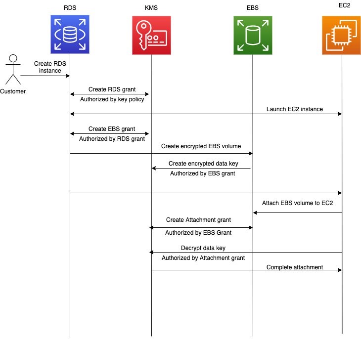
The process described in the previous paragraphs is graphically shown in Figure 1:
 
Figure 1: How Amazon RDS uses Amazon EC2, Amazon EBS, and AWS KMS to create an encrypted RDS instance

Considering all the AWS KMS key permissions that are added and removed as a part of launching a database, you might ask why not just use the key policy document to make these changes? A KMS key allows only one key policy with a maximum document size of 32 KB. Because one key could be used to encrypt any number of AWS resources, trying to dynamically add and remove scoped-down permissions related to each resource to the key policy document creates two risks. First, the maximum allowable size of the key policy document (32KB) might be exceeded. Second, depending on how many resources are being accessed concurrently, you may exceed the request rate quota for the PutKeyPolicy API action in AWS KMS.

In contrast, there can be any number of grants on a given AWS KMS key, each grant specifying a scoped-down permission for the use of a KMS key with any AWS service that integrated with AWS KMS. Grant creation and deletion is also designed for much higher-volume request rates than modifications to the key policy document. Finally, permission to call PutKeyPolicy is a highly privileged permission, as it lets the caller make unrestricted changes to the permissions on the key, including changes to administrative permissions to disable or schedule the key for deletion. Grants on a key can only allow permissions to use the key, not administer the key. Also, grants that allow the creation of other grants by other IAM principals prohibit the escalation of privilege. In the RDS example above, the permissions RDS receives from the IAM principal in your account during the first CreateGrant request cannot be more permissive than what you defined for the IAM principal in the KMS key policy. The permissions RDS gives to EC2 and EBS during the database creation process cannot be more permissive than the original permission RDS has from the initial grant. This design ensures that AWS services cannot escalate their privileges and use your KMS key for purposes different than what you intend.

Best practices for using AWS KMS grants

AWS KMS grants are a powerful tool to dynamically define permissions to use keys. They are automatically created when you use server-side encryption features in various AWS services. You can also use grants to control permission in your own applications that perform client-side encryption. Here are some best practices to consider:

  • Design the permissions to be as scoped down as possible. Use a specific grantee principal, such as an IAM role, and give the principal access only to the AWS KMS API actions that are needed. You can further limit the scope of grants with the Encryption Context parameter by using any element you want to ensure callers are using the AWS KMS key only for the intended purpose. Below is a specific example that grants AWS account 123456789012 permission to call the GenerateDataKey or Decrypt APIs, but only if the supplied encryption context for customerID is 5678.
    {Actions: 'GenerateDataKey, Decrypt', Grantee Principal: '123456789012', Encryption Context: '"customerID": "5678"'}
    

    This grant could prevent your application from decrypting data belonging to customer “5678” without explicitly passing the expected customerID in the request to AWS KMS. This may be a useful defense-in-depth mechanism to prevent unauthorized access to your customers’ data if your application’s AWS credentials were compromised and used from a different caller who doesn’t know that encryption context is a required parameter for all reads and writes in order to encrypt and decrypt data.

    For more information on how you can use encryption context in AWS KMS permissions, requests, and AWS CloudTrail logs, see How to Protect the Integrity of Your Encrypted Data by Using AWS Key Management Service and EncryptionContext.

  • Remember that grants don’t automatically expire. Your code needs to retire or revoke them once you know the permission is no longer needed on the KMS key. Grants that aren’t retired are leftover permissions that might create a security risk for encrypted resources. See retiring and revoking grants in the AWS KMS developer guide for more detail.
  • Avoid creating duplicate grants. A duplicate grant is a grant that shares the same AWS KMS key ID, API actions, grantee principal, encryption context, and name. If you retire the original grant after use and not the duplicates, then the leftover duplicate grants can lead to unintended access to encrypt or decrypt data.

Recent performance improvements to AWS KMS grants: Removing a resource quota

For customers who use AWS KMS to encrypt resources in AWS services that use grants, there used to be cases where AWS KMS had to enforce a quota on the number of concurrently active resources that could be encrypted under the same KMS key. For example, customers of Amazon RDS, Amazon WorkSpaces, or Amazon EBS would run into this quota at very large scale. This was the Grants for a given principal per key quota and was previously set to 500. You might have seen the error message “Keys only support 500 grants per grantee principal in this region” when trying to create a resource in one of these services.

We recently made a change to AWS KMS to remove this quota entirely and this error message no longer exists. With this quota removed, you can now attach unlimited grants to any KMS key when using any AWS service.

Summary

In this blog post, you’ve seen how services such as Amazon RDS use AWS KMS grants to pass scoped-down permissions through the Amazon EC2 and Amazon EBS instances. You also saw some best practices for using AWS KMS grants in your own applications. Finally, you learned about how AWS KMS has improved grants by removing one of the resource quotas.

Below are some additional resources for AWS KMS and grants.

If you have feedback about this post, submit comments in the Comments section below.

Want more AWS Security how-to content, news, and feature announcements? Follow us on Twitter.

Author

Rick Yin

Rick is a software development engineer on the AWS KMS team. His current focus is helping to scale AWS KMS to meet increasing customer demand by making sure we can serve our requests at ultra-low latency and ultra-high availability. In his free time, Rick enjoys learning about history and trying to stay in shape. He has recently taken up rowing.