Post Syndicated from James Beswick original https://aws.amazon.com/blogs/compute/uploading-large-objects-to-amazon-s3-using-multipart-upload-and-transfer-acceleration/
This post is written by Tam Baghdassarian, Cloud Application Architect, Rama Krishna Ramaseshu, Sr Cloud App Architect, and Anand Komandooru, Sr Cloud App Architect.
Web and mobile applications must often upload objects to the AWS Cloud. For example, services such as Amazon Photos allow users to upload photos and large video files from their browser or mobile application.
Amazon S3 can be ideal to store large objects due to its 5-TB object size maximum along with its support for reducing upload times via multipart uploads and transfer acceleration.
Overview
Developers who must upload large files from their web and mobile applications to the cloud can face a number of challenges. Due to underlying TCP throughput limits, a single HTTP connection cannot use the full bandwidth available, resulting in slower upload times. Furthermore, network latency and quality can result in poor or inconsistent user experience.
Using S3 features such as presigned URLs and multipart upload, developers can securely increase throughput and minimize upload retries due to network errors. Additionally, developers can use transfer acceleration to reduce network latency and provide a consistent user experience to their web and mobile app users across the globe.
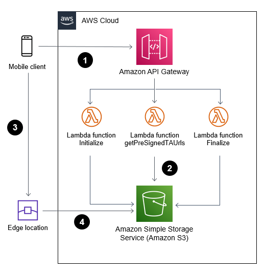
This post references a sample application consisting of a web frontend and a serverless backend application. It demonstrates the benefits of using S3’s multipart upload and transfer acceleration features.
Solution overview:
- Web or mobile application (frontend) communicates with AWS Cloud (backend) through Amazon API Gateway to initiate and complete a multipart upload.
- AWS Lambda functions invoke S3 API calls on behalf of the web or mobile application.
- Web or mobile application uploads large objects to S3 using S3 transfer acceleration and presigned URLs.
- File uploads are received and acknowledged by the closest edge location to reduce latency.
Using S3 multipart upload to upload large objects
A multipart upload allows an application to upload a large object as a set of smaller parts uploaded in parallel. Upon completion, S3 combines the smaller pieces into the original larger object.
Breaking a large object upload into smaller pieces has a number of advantages. It can improve throughput by uploading a number of parts in parallel. It can also recover from a network error more quickly by only restarting the upload for the failed parts.
Multipart upload consists of:
- Initiate the multipart upload and obtain an upload id via the CreateMultipartUpload API call.
- Divide the large object into multiple parts, get a presigned URL for each part, and upload the parts of a large object in parallel via the UploadPart API call.
- Complete the upload by calling the CompleteMultipartUpload API call.
When used with presigned URLs, multipart upload allows an application to upload the large object using a secure, time-limited method without sharing private bucket credentials.
This Lambda function can initiate a multipart upload on behalf of a web or mobile application:
const multipartUpload = await s3. createMultipartUpload(multipartParams).promise()
return {
    statusCode: 200,
    body: JSON.stringify({
        fileId: multipartUpload.UploadId,
        fileKey: multipartUpload.Key,
      }),
    headers: {
      'Access-Control-Allow-Origin': '*'
    }
};
The UploadId is required for subsequent calls to upload each part and complete the upload.
Uploading objects securely using S3 presigned URLs
A web or mobile application requires write permission to upload objects to a S3 bucket. This is usually accomplished by granting access to the bucket and storing credentials within the application.
You can use presigned URLs to access S3 buckets securely without the need to share or store credentials in the calling application. In addition, presigned URLs are time-limited (the default is 15 minutes) to apply security best practices.
A web application calls an API resource that uses the S3 API calls to generate a time-limited presigned URL. The web application then uses the URL to upload an object to S3 within the allotted time, without having explicit write access to the S3 bucket. Once the presigned URL expires, it can no longer be used.
When combined with multipart upload, a presigned URL can be generated for each of the upload parts, allowing the web or mobile application to upload large objects.
This example demonstrates generating a set of presigned URLs for index number of parts:
    const multipartParams = {
        Bucket: bucket_name,
        Key: fileKey,
        UploadId: fileId,
    }
    const promises = []

    for (let index = 0; index < parts; index++) {
        promises.push(
            s3.getSignedUrlPromise("uploadPart", {
            ...multipartParams,
            PartNumber: index + 1,
            Expires: parseInt(url_expiration)
            }),
        )
    }
    const signedUrls = await Promise.all(promises)
Prior to calling getSignedUrlPromise, the client must obtain an UploadId via CreateMultipartUpload. Read Generating a presigned URL to share an object for more information.
Reducing latency by using transfer acceleration
By using S3 transfer acceleration, the application can take advantage of the globally distributed edge locations in Amazon CloudFront. When combined with multipart uploads, each part can be uploaded automatically to the edge location closest to the user, reducing the upload time.
Transfer acceleration must be enabled on the S3 bucket. It can be accessed using the endpoint bucketname.s3-acceleration.amazonaws.com or bucketname.s3-accelerate.dualstack.amazonaws.com to connect to the enabled bucket over IPv6.
Use the speed comparison tool to test the benefits of the transfer acceleration from your location.
You can use transfer acceleration with multipart uploads and presigned URLs to allow a web or mobile application to upload large objects securely and efficiently.
Transfer acceleration needs must be enabled on the S3 bucket. This example creates an S3 bucket with transfer acceleration using CDK and TypeScript:
const s3Bucket = new s3.Bucket(this, "document-upload-bucket", {
      bucketName: “BUCKET-NAME”,
      encryption: BucketEncryption.S3_MANAGED,
      enforceSSL: true,
      transferAcceleration: true,
      removalPolicy: cdk.RemovalPolicy.DESTROY
    });
After activating transfer acceleration on the S3 bucket, the backend application can generate transfer acceleration-enabled presigned URLs. by initializing the S3 SDK:
s3 = new AWS.S3({useAccelerateEndpoint: true});The web or mobile application then use the presigned URLs to upload file parts.
See S3 transfer acceleration for more information.
Deploying the test solution
To set up and run the tests outlined in this blog, you need:
- An AWS account.
- Install and configure AWS CLI.
- Install and bootstrap AWS CDK.
- Deploy the backend and frontend solution at the following git repository.
- A sufficiently large test upload file of at least 100 MB.
To deploy the backend:
- Clone the repository to your local machine.
- From the backendv2 folder, install all dependencies by running:
npm install - Use CDK to deploy the backend to AWS:
cdk deploy --context env="randnumber" --context whitelistip="xx.xx.xxx.xxx"
You can use an additional context variable called “urlExpiry” to set a specific expiration time on the S3 presigned URL. The default value is set at 300 seconds. A new S3 bucket with the name “document-upload-bucket-randnumber” is created for storing the uploaded objects, and the whitelistip value allows API Gateway access from this IP address only.
Note the API Gateway endpoint URL for later.
To deploy the frontend:
- From the frontend folder, install the dependencies:
npm install - To launch the frontend application from the browser, run:
npm run start
Testing the application

To test the application:
- Launch the user interface from the frontend folder:
npm run - Enter the API Gateway address in the API URL textbox.Select the maximum size of each part of the upload (the minimum is 5 MB) and the number of parallel uploads. Use your available bandwidth, TCP window size, and retry time requirements to determine the optimal part size. Web browsers have a limit on the number of concurrent connections to the same server. Specifying a larger number of concurrent connections results in blocking on the web browser side.
- Decide if transfer acceleration should be used to further reduce latency.
- Choose a test upload file.
- Use the Monitor section to observe the total time to upload the test file.
Experiment with different values for part size, number of parallel uploads, use of transfer acceleration and the size of the test file to see the effects on total upload time. You can also use the developer tools for your browser to gain more insights.
Test results
The following tests have the following characteristics:
- The S3 bucket is located in the US East Region.
- The client’s average upload speed is 79 megabits per second.
- The Firefox browser uploaded a file of 485 MB.
Test 1 – Single part upload without transfer acceleration
To create a baseline, the test file is uploaded without transfer acceleration and using only a single part. This simulates a large file upload without the benefits of multipart upload. The baseline result is 72 seconds.

Test 2 – Single upload with transfer acceleration
The next test measured upload time using transfer acceleration while still maintaining a single upload part with no multipart upload benefits. The result is 43 seconds (40% faster).

Test 3 – Multipart upload without transfer acceleration
This test uses multipart upload by splitting the test file into 5-MB parts with a maximum of six parallel uploads. Transfer acceleration is disabled. The result is 45 seconds (38% faster).

Test 4 – Multipart upload with transfer acceleration
For this test, the test file is uploaded by splitting the file into 5-MB parts with a maximum of six parallel uploads. Transfer acceleration is enabled for each upload. The result is 28 seconds (61% faster).

The following chart summarizes the test results.
| Multipart upload | Transfer acceleration | Upload time |
| No | No | 72s |
| Yes | No | 43s |
| No | Yes | 45s |
| Yes | Yes | 28s |
Conclusion
This blog shows how web and mobile applications can upload large objects to Amazon S3 in a secured and efficient manner when using presigned URLs and multipart upload.
Developers can also use transfer acceleration to reduce latency and speed up object uploads. When combined with multipart upload, you can see upload time reduced by up to 61%.
Use the reference implementation to start incorporating multipart upload and S3 transfer acceleration in your web and mobile applications.
For more serverless learning resources, visit Serverless Land.