Post Syndicated from Anton Aleksandrov original https://aws.amazon.com/blogs/compute/building-responsive-apis-with-amazon-api-gateway-response-streaming/
Today, AWS announced support for response streaming in Amazon API Gateway to significantly improve the responsiveness of your REST APIs by progressively streaming response payloads back to the client. With this new capability, you can use streamed responses to enhance user experience when building LLM-driven applications (such as AI agents and chatbots), improve time-to-first-byte (TTFB) performance for web and mobile applications, stream large files, and perform long-running operations while reporting incremental progress using protocols such as server-sent events (SSE).
In this post you will learn about this new capability, the challenges it addresses, and how to use response streaming to improve the responsiveness of your applications.
Overview
Consider this scenario – you’re running an AI-powered agentic application that uses an Amazon Bedrock foundation model. Your users interact with the application through an API, asking complex questions that require detailed responses. Before response streaming, users would send their prompts and wait to eventually receive the application response, sometimes for tens of seconds. This awkward pause between questions and responses created a disconnected, unnatural experience.
With the new API Gateway response streaming capability, the interaction through the API becomes much more fluid and natural. As soon as your application starts processing the model response, you can stream it back to your users using the API Gateway.
The following animation illustrates this significant user experience improvement. The prompt on the left is processed using a non-streaming response with user having to wait for several seconds to receive the result. The prompt on the right is using the new API Gateway response streaming, significantly reducing TTFB and improving user experience.
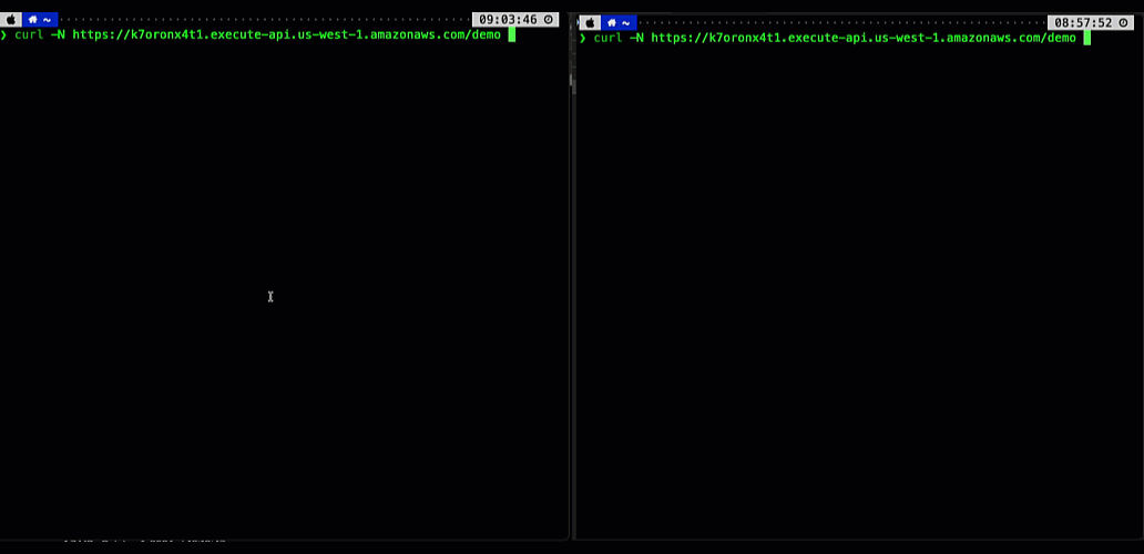
Figure 1. Comparing user experience before (left) and after (right) enabling API Gateway response streaming when returning a response from a Bedrock foundational model.
Your users can now see AI responses appear in real-time, word by word, just like watching someone type. This immediate feedback makes your applications feel more responsive and engaging, keeping users connected throughout the interaction. In addition, you don’t have to worry about response size limits or implement complex workarounds – the streaming happens automatically and efficiently, letting you focus on building great user experiences rather than managing infrastructure constraints.
Understanding response steaming
In the traditional request-response model, responses must be fully computed before being sent to the client. This can negatively impact user experience – the client must wait for the complete response to be generated on the server-side and transmitted over-the-wire. This is especially pronounced in interactive, latency-sensitive cloud applications such as AI agents, chatbots, virtual assistants, or music generators.
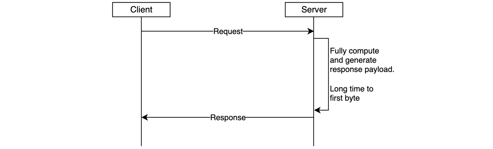
Figure 2. Response is returned to the client only after it’s been fully generated, increasing time-to-first-byte latency.
Another important scenario is returning larger response payloads, such as images, large documents, or datasets. In some cases, these payloads may exceed the 10 MB response size limit or default integration timeout limit of 29 seconds of API Gateway. Before the launch of response streaming, developers worked around these limitations by using pre-signed Amazon S3 URLs to download large responses or accepting lower RPS for an increase in timeout. While functional, these workarounds introduced additional latency and architectural complexity.
With response streaming support you can address these challenges. You can now update your REST APIs to return streamed responses, significantly enhancing user experience, improving TTFB performance, supporting response payload sizes to exceed 10 MB, and serving requests that can take up to 15 minutes.
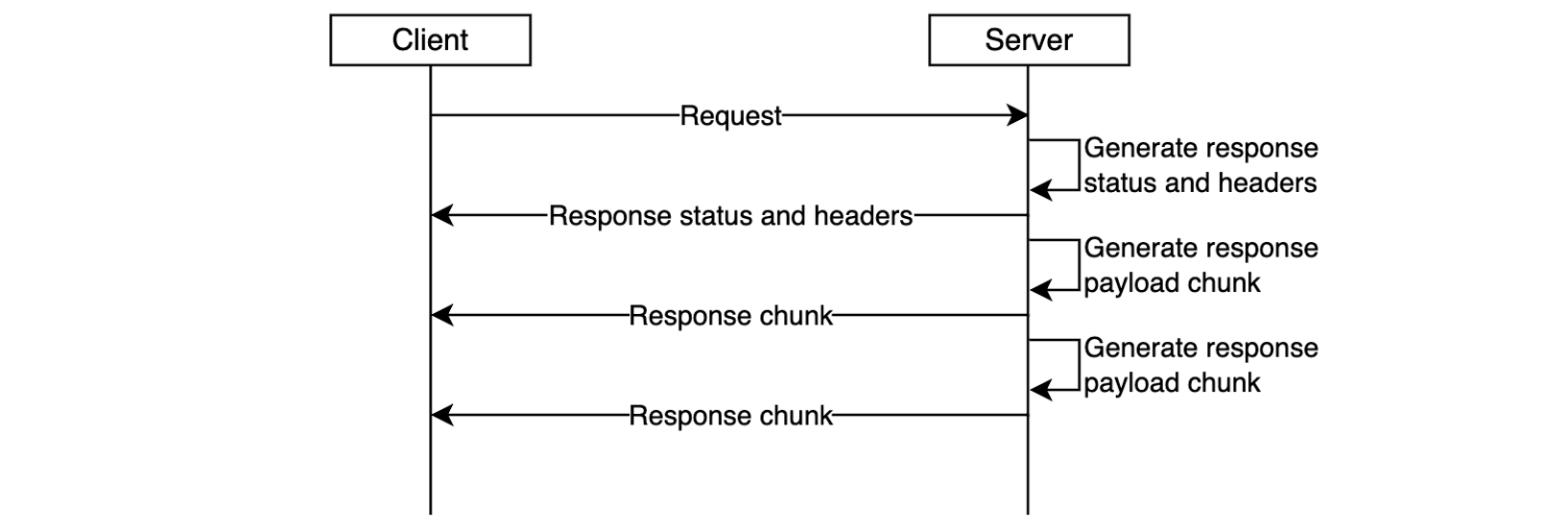
Figure 3. Response streaming reduces time-to-first-byte and improves user experience.
The response streaming capability is already delivering significant performance for organizations:
“Working closely with the AWS teams to enable response streaming was instrumental in advancing our roadmap to deliver the most performant storefront experiences for our largest customers at Salesforce Commerce Cloud. Our collaboration exceeded our Core Web Vital goals; we saw our Total Blocking Time metrics drop by over 98%, which will enable our customers to drive higher revenue and conversion rates.”, says Drew Lau, Senior Director of Product Management at Salesforce.
Response streaming is supported for any HTTP-proxy integration, AWS Lambda functions (using proxy integration mode), and private integrations. To get started, configure your API integration to stream the response from your backend, as described in the following sections, and redeploy your API for changes to take effect.
Getting started with response streaming
To enable response streaming for your REST APIs, update your integration configuration to set the response transfer mode to STREAM. This enables API Gateway to start streaming the response to the client as soon as response bytes become available. When using response streaming, you can configure request timeout up to 15 minutes. For best time to first byte user experience, AWS strongly recommends your backend integration also implements response streaming.
You can enable response streaming in several different ways, as illustrated in the following snippets:
Using the API Gateway console, when creating method integrations, select Stream for the Response transfer mode.
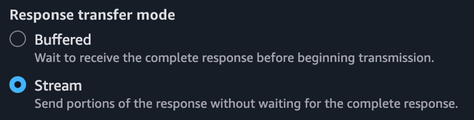
Figure 4. Enabling response streaming in API Gateway Console.
Setting response transfer mode using the Open API spec:
paths:
  /products:
    get:
      x-amazon-apigateway-integration:
        httpMethod: "GET"
        uri: "https://example.com"
        type: "http_proxy"
        timeoutInMillis: 300000
        responseTransferMode: "STREAM"
Setting response transfer mode using infrastructure-as-code (IaC) frameworks, such as AWS CloudFormation. Note the /response-streaming-invocations Uri fragment, it tells API Gateway to use the Lambda InvokeWithResponseStreaming endpoint:
MyProxyResourceMethod:
  Type: 'AWS::ApiGateway::Method'
  Properties:
    RestApiId: !Ref LambdaSimpleProxy
    ResourceId: !Ref ProxyResource
    HttpMethod: ANY
    Integration:
      Type: AWS_PROXY
      IntegrationHttpMethod: POST
      ResponseTransferMode: STREAM
      Uri: !Sub arn:aws:apigateway:${APIGW_REGION}:lambda:path/2021-11-
           15/functions/${FN_ARN}/response-streaming-invocations
Updating response transfer mode using the AWS CLI:
aws apigw update-integration \
   --rest-api-id a1b2c2 \
   --resource-id aaa111 \
   --http-method GET \
   --patch-operations "op='replace',path='/responseTransferMode',value=STREAM" \
   --region us-west-2
Using response streaming with Lambda functions
When using Lambda functions as a downstream integration endpoint, your Lambda functions must be streaming-enabled. The API Gateway uses the InvokeWithResponseStreaming API to invoke functions, as illustrated in the following diagram, and requires Lambda proxy integration. See the API Gateway documentation for additional guidance.
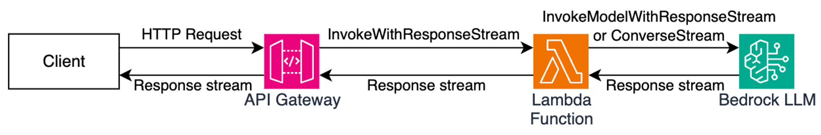
Figure 5. Using API Gateway response streaming with Lambda functions for interactive AI applications.
When you use response streaming with Lambda functions, API Gateway expects the handler response stream to contain the following components (in order):
- JSON response metadata – Must be a valid JSON object and can only contain statusCode, headers, multiValueHeaders, and cookies fields (all optional). Metadata cannot be an empty string; at a minimum it must be an empty JSON object.
- The 8-null-byte delimiter – Lambda adds this delimiter automatically when you use the built-in awslambda.HttpResponseStream.from() method, as illustrated below. When not using this method, you’re responsible for adding the delimiter yourself.
- Response payload – Can be empty.
The following code snippet illustrates how you can return a streamed response from your Lambda functions so it will be compatible with API Gateway response streaming:
export const handler = awslambda.streamifyResponse(
   async (event, responseStream, context) => {

      const httpResponseMetadata = {
         statusCode: 200,
         headers: {
            'Content-Type': 'text/plain',
            'X-Custom-Header': 'some-value'
         }
      };

      responseStream = awslambda.HttpResponseStream.from(
         responseStream,
         httpResponseMetadata
      );

      responseStream.write('hello');
      await new Promise(r => setTimeout(r, 1000));
      responseStream.write(' world');
      await new Promise(r => setTimeout(r, 1000));
      responseStream.write('!!!');
      responseStream.end();
   }
);
Refer to the API Gateway documentation for further implementation guidelines.
Using response streaming with HTTP Proxy integrations
You can stream HTTP responses from your applications used as downstream integration endpoints, for example web servers running on Amazon Elastic Container Service (Amazon ECS) or Amazon Elastic Kubernetes Service (Amazon EKS). In this case, you must use HTTP_PROXY integration and specify the response transfer mode as STREAM (using the console, AWS CLI, or IaC). Redeploy your API after modifying it.
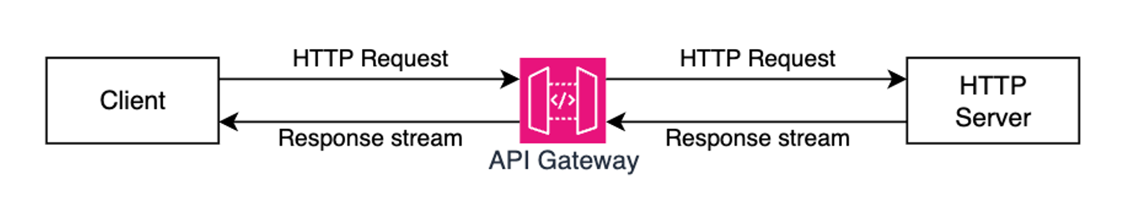
Figure 6. Using API Gateway response streaming with HTTP server applications.
Once API Gateway receives a streaming response from your application, it will wait until the HTTP headers block transfer is complete. Then, it will send to the client an HTTP response status code and headers, followed by the content from your application as it gets received by the API Gateway service. It will continue streaming response from your application to the client until the stream ends (up to 15 minutes).
Many popular API and web application development frameworks provide response streaming abstractions. The following code snippet illustrates how you can implement HTTP response streaming using FastAPI:
app = FastAPI()

async def stream_response():
   yield b"Hello "
   await asyncio.sleep(1)
   yield b"World "
   await asyncio.sleep(1)
   yield b"!"

@app.get("/")
async def main():
   return StreamingResponse(stream_response(), media_type="text/plain")
Adding real-time response streaming to your HTTP clients
Different HTTP clients have different ways to process streamed response fragments as they arrive. The following code snippet illustrates how to process a streamed response with a Node.js application:
const request = http.request(options, (response)=>{
   response.on('data', (chunk) => {
      console.log(chunk);
   });

   response.on('end', () => {
      console.log('Response complete’);
   });
});

request.end();
When using CURL, you can use the –no-buffer argument to print response fragments as they arrive.
curl --no-buffer {URL}Sample code
Clone this sample project from GitHub to see API Gateway response streaming in action. Follow instructions in the README.md to provision the sample project in your AWS account.
Considerations
Before you enable response streaming, consider:
- Response streaming is available for REST APIs and can be used with HTTP_PROXY integrations, Lambda integrations (in proxy mode), and private integrations.
- You can use API Gateway response streaming with any endpoint type, such as Regional, Private, and Edge-optimized, with or without custom domain names.
- When using response streaming, you can configure response timeouts up to 15 minutes, according to your scenario requirements.
- All streaming responses from Regional or Private endpoints are subject to a 5-minute idle timeout. All streaming responses from edge-optimized endpoints are subject to a 30-second idle timeout.
- Within each streaming response, the first 10MB of response payload is not subject to any bandwidth restrictions. Response payload data exceeding 10MB is restricted to 2MB/s.
- Response streaming is compatible with API Gateway security capabilities such as authorizers, WAF, access controls, TLS/mTLS, request throttling, and access logging.
- When processing streamed responses, the following features are not supported: response transformation with VTL, integration response caching, and content encoding.
- Always protect your APIs against unauthorized access and other potential security threats by implementing proper authorization with Lambda Authorizers or Amazon Cognito User Pools. Read REST API protection documentation and API Gateway security documentation for additional details.
Observability
You can continue using existing observability capabilities, such as execution logs, access logs, AWS X-Ray integration, and Amazon CloudWatch metrics with API Gateway response streaming.
In addition to the existing access logs variables, the following new variables are available:
- $content.integration.responseTransferMode – the response transfer mode of your integration. This can be either BUFFERED or STREAMED.
- $context.integration.timeToAllHeaders – the time between when API Gateway establishes the integration connection to when it receives all integration response headers from the client.
- $context.integration.timeToFirstContent – the time between when API Gateway establishes the integration connection to when it receives the first content bytes.
See API Gateway documentation for more information.
Pricing
With this new capability, you continue to pay the same API Invoke rates for streamed responses. Each 10MB of response data, rounded up to the nearest 10MB, is billed as a single request. See API Gateway pricing page for additional details.
Conclusion
The new response streaming capability for Amazon API Gateway enhances how you can build and deliver responsive APIs in the cloud. With immediate streaming of response data as it becomes available, you can significantly improve time-to-first-byte performance and overcome traditional payload size and timeout limitations. This is particularly valuable for AI-powered applications, file transfers, and interactive web experiences that demand real-time responsiveness.
To learn more about API Gateway response streaming see the service documentation.
To learn more about building Serverless architectures see Serverless Land.


 Happy Lunar New Year! Wishing you a year filled with joy, success, and endless opportunities! May the Year of the Dragon bring uninterrupted connections and limitless growth