Post Syndicated from James Beswick original https://aws.amazon.com/blogs/compute/using-aws-lambda-to-run-external-transactions-on-db2-for-ibm-i/
This post is written by Basil Lin, Cloud Application Architect, and Jud Neer, Delivery Practice Manager.
Db2 for IBM i (Db2) is a relational database management system that can pose connectivity challenges with cloud environments because of a lack of native support. However, by using Docker on Amazon ECR and AWS Lambda container images, you can transfer data between the two environments with a serverless architecture.
While mainframe modernization solutions are helping customers migrate from on-premises technologies to agile cloud solutions, a complete migration is not always immediately possible. AWS offers broad modernization support from rehosting to refactoring, and platform augmentation is a common scenario for customers getting started on their cloud journey.
Db2 is a common database in on-premises workloads. One common use case of platform augmentation is maintaining Db2 as the existing system-of-record while rehosting applications in AWS. To ensure Db2 data consistency, a change data capture (CDC) process must be able to capture any database changes as SQL transactions. A mechanism then runs these transactions on the existing Db2 database.
While AWS provides CDC tools for multiple services, converting and running these changes for Db2 requires proprietary IBM drivers. Conventionally, you can implement this by hosting a stream-processing application on a server. However, this approach relies on traditional server architecture. This may be less efficient, incur higher overhead, and may not meet availability requirements.
To avoid these issues, you can build this transaction mechanism using a serverless architecture. This blog post’s approach uses ECR and Lambda to externalize and run serverless, on-demand transactions on Db2 for IBM i databases.
Overview
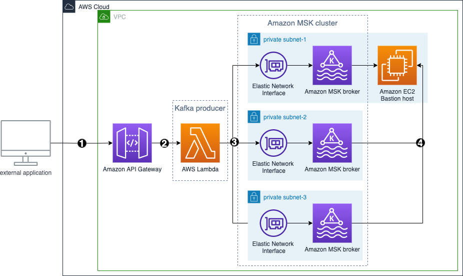
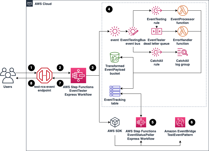
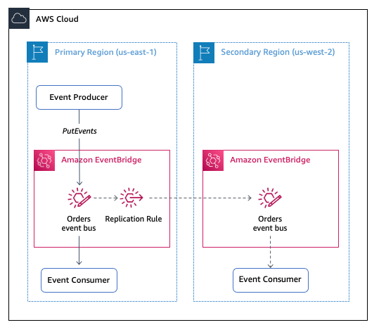
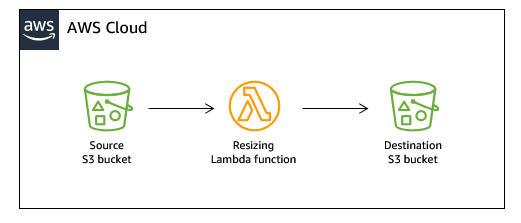
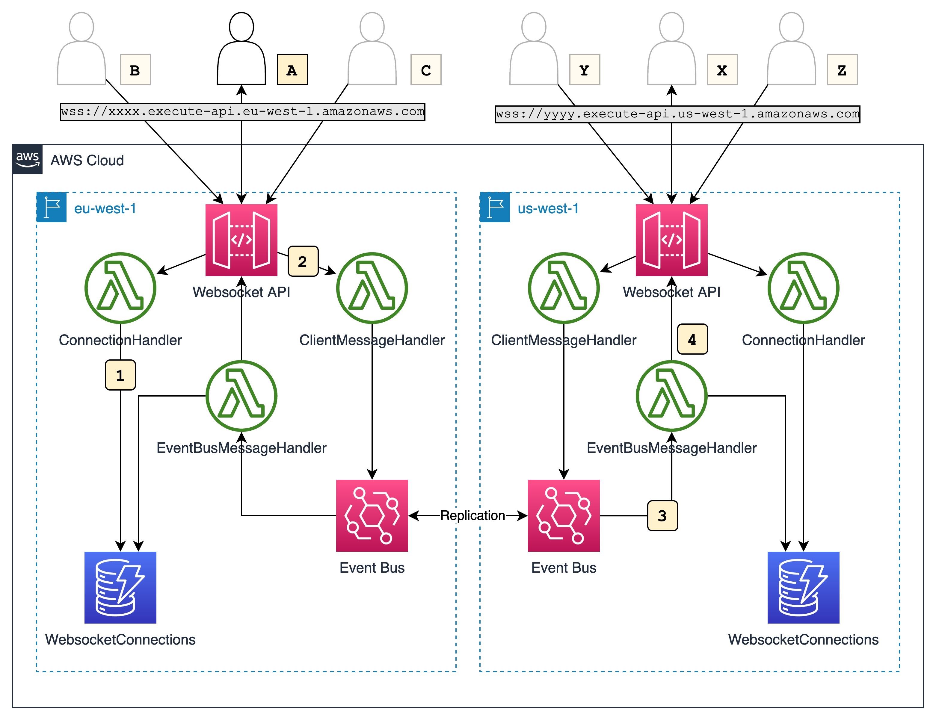
The solution you deploy relies on a Lambda container image to run SQL queries on Db2. While you provide your own Lambda invocation methods and queries, this solution includes the drivers and connection code required to interface with Db2. The following architecture diagram shows this generic solution with no application-specific triggers:
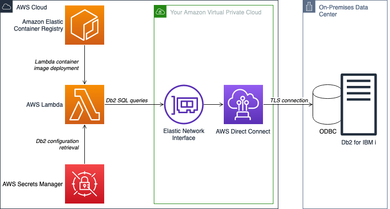
This solution builds a Docker image containerized with Db2 interfacing code. The code consists of a Lambda handler to run the specified database transactions, a base class that helps create database Python functions via Open Database Connectivity (ODBC), and finally a forwarder class to establish encrypted connections with the target database.
Deployment scripts create the Docker image, deploy the image to ECR, and create a Lambda function from the image. Lambda then runs your queries on your target Db2 database. This solution does not include the Lambda invocation trigger, the Amazon VPC, and the AWS Direct Connect connection as part of the deployment, but these components may be necessary depending on your use case. The README in the sample repository shows the complete deployment prerequisites.
To interface with Db2, the Lambda function establishes an ODBC session using a proprietary IBM driver. This enables the use of high-level ODBC functions to manipulate the Db2 database management system.
Even with the proprietary driver, ODBC does not properly support TLS encryption with Db2. During testing, enabling the TLS encryption option can cause issues with database connectivity. To work around this limitation, a forwarding package captures all ODBC traffic and forwards packets using TLS encryption to the database. The forwarder opens a local socket listener on port 8471 for unencrypted loopback connections. Once the Lambda function initializes an unencrypted ODBC connection locally, the forwarding package then captures, encrypts, and forwards all ODBC calls to the target Db2 database. This method allows Lambda to form encrypted connections with your target database while still using ODBC to control transactions.
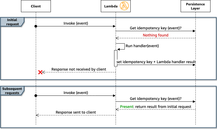
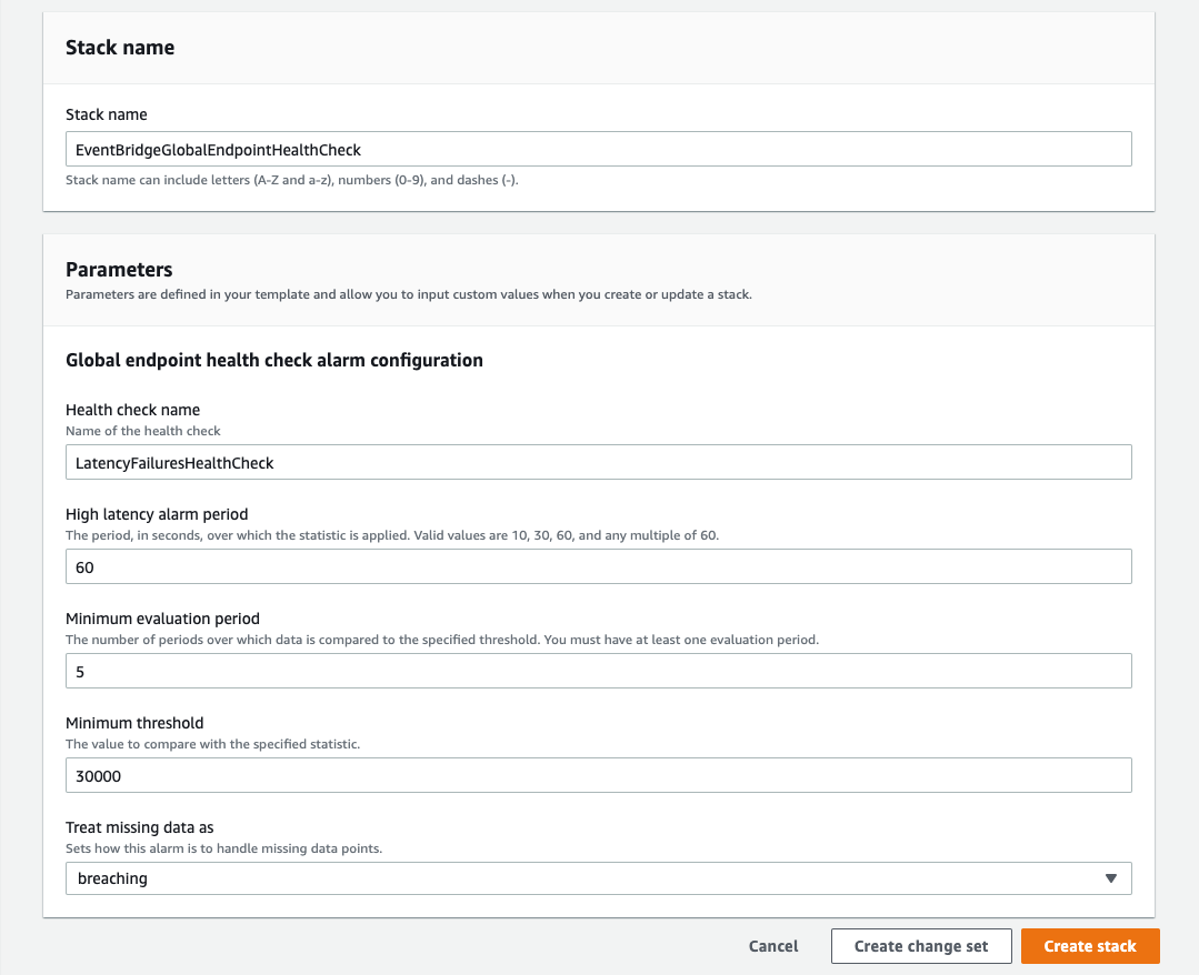
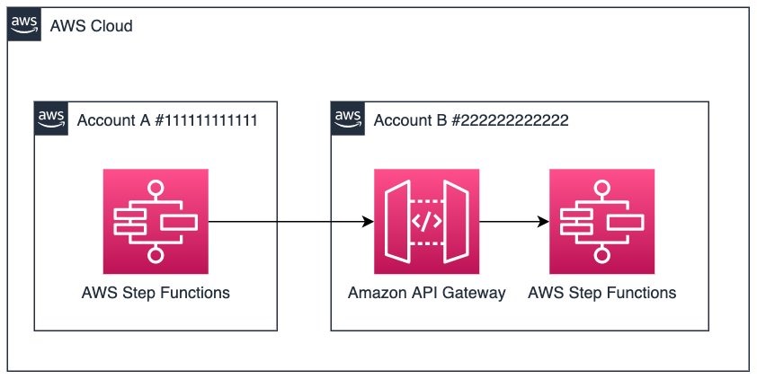
With secure connectivity in place, you can invoke the Lambda function. The function starts the forwarder and retrieves Db2 access credentials from AWS Secrets Manager, as shown in the following diagram. The function then attempts an ODBC loopback connection to send transactions to the forwarder.
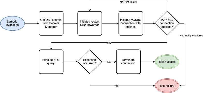
If the connection is successful, the Lambda function runs the queries, and the forwarder sends the queries to the target Db2. However, if the connection fails, it makes a second connection attempt. The second attempt consists of both restarting the forwarder module and the loopback connection. If the second attempt fails again, the function errors out.
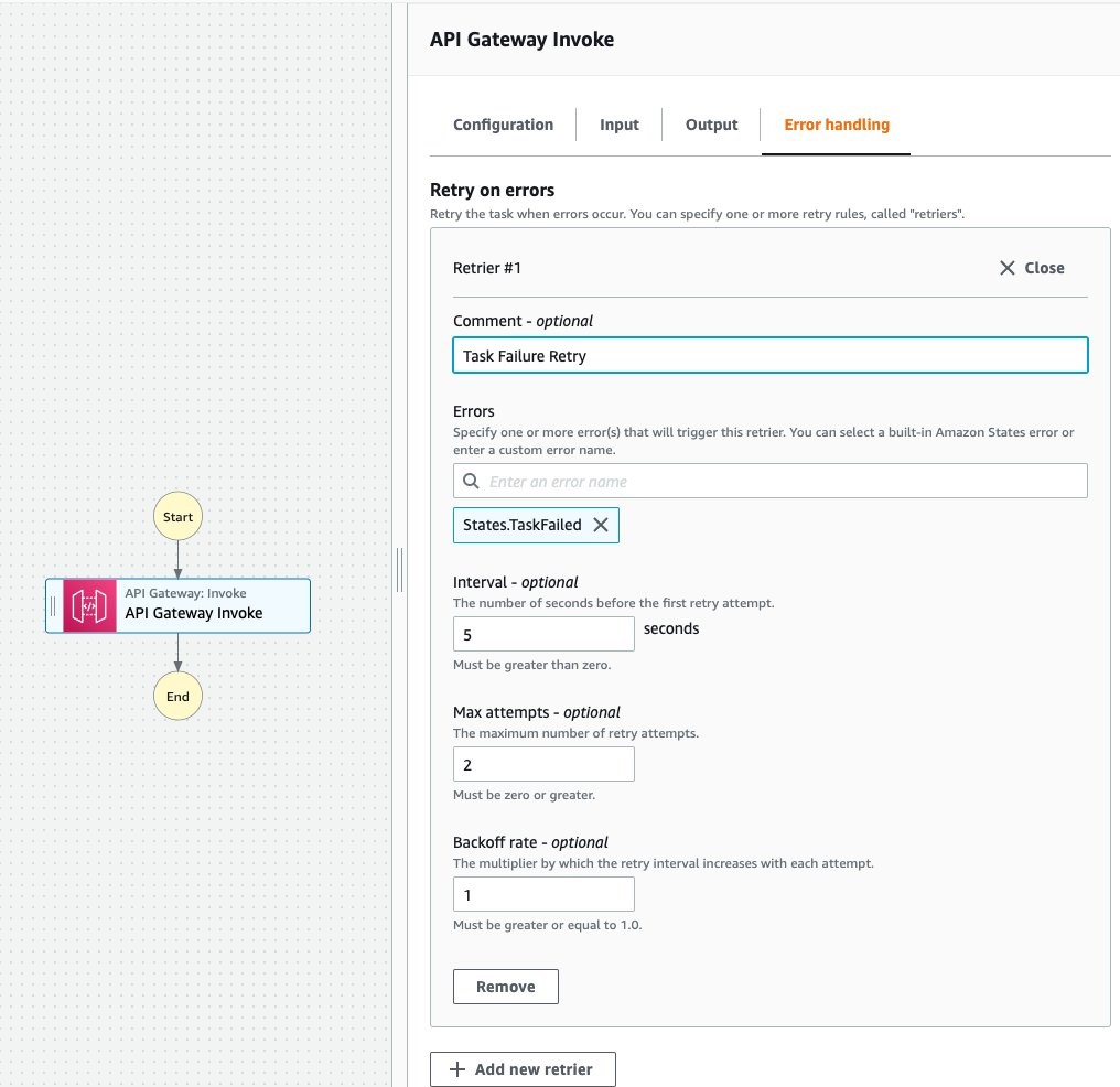
After the transactions complete, a cleanup process runs and the function exits with a success status, unless an exception occurs during the function invocation. If an exception arises during the transaction, the function exits with a failure status. This is an important consideration when building retry mechanisms. You must review Lambda exit statuses to prevent default AWS retry mechanisms from causing unintended invocations.
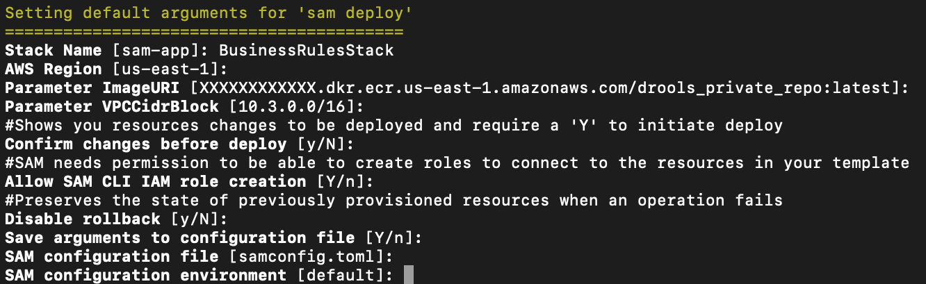
To simplify deployment, the solution contains scripts you can use. Once you provide AWS credentials, the deployment script deploys a base set of infrastructure into AWS, including the ECR repository for the Docker images and the Secrets Manager secret for the Db2 configuration details.
The deployment script also asks for Db2 configuration details. After you finish entering these, the script sends the information to AWS to configure the previously deployed secret.
Once the secret configuration is complete, the script then builds and pushes a base Docker image to the deployed ECR repository. This base image contains a few basic Python prerequisite libraries necessary for the final code, and also the RPM driver for interfacing with Db2 via ODBC.
Finally, the script builds the solution infrastructure and deploys it into the AWS Cloud. Using the base image in ECR, it creates a Lambda function from a new Docker container image containing the SQL queries and the ODBC transaction code. After deployment, the solution is ready for testing and customization for your use case.
Prerequisites
Before deployment, you must have the following:
- The cloned code repository locally.
- A local environment configured for deployment.
- Amazon VPC and networking configured with Db2 access.
You can find detailed prerequisites and associated instructions in the README file.
Deploying the solution
The deployment creates an ECR repository, a Secrets Manager secret, a Lambda function built from a base container image uploaded to the ECR repo, and associated elastic network interfaces (ENIs) for VPC access.
Because of the complexity of the deployment, a combination of Bash and Python scripts automates the process by automatically deploying infrastructure templates, building and pushing container images, and prompting for input where required. Refer to the README included in the repository for detailed instructions.
To deploy:
- Ensure you have met the prerequisites.
- Open the README file in the repository and follow the deployment instructions
- Configure your local AWS CLI environment.
- Configure the project environment variables file.
- Run the deployment scripts.
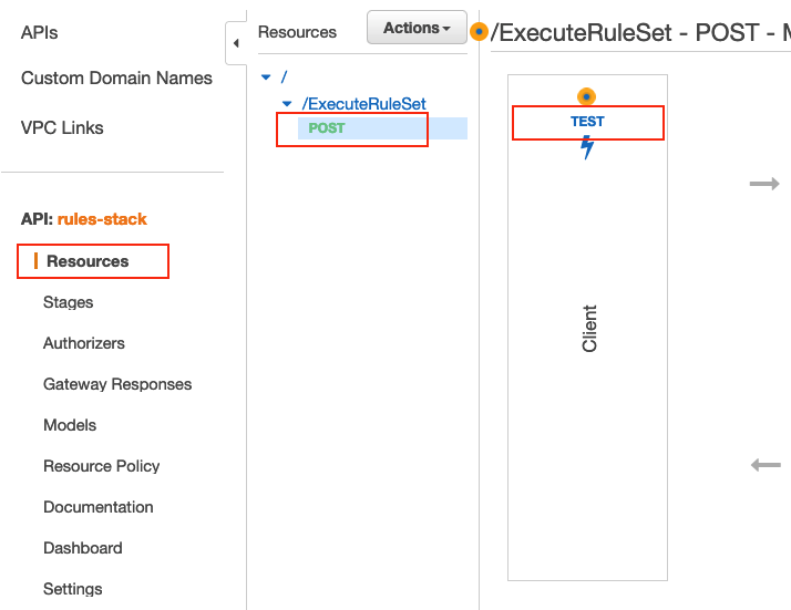
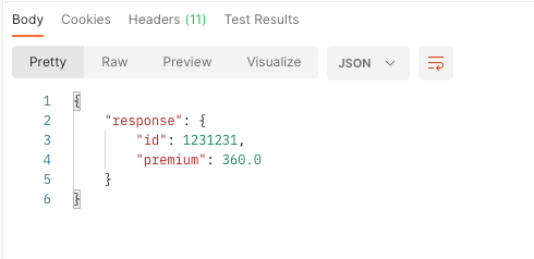
- Test connectivity by invoking the deployed Lambda function
- Change infrastructure and code for specific queries and use cases
Cleanup
To avoid incurring additional charges, ensure that you delete unused resources. The README contains detailed instructions. You may either manually delete the resources provisioned through the AWS Management Console, or use the automated cleanup script in the repository. The deletion of resources may take up to 45 minutes to complete because of the ENIs created for Lambda in your VPC.
Conclusion
In this blog post, you learn how to run external transactions securely on Db2 for IBM i databases using a combination of Amazon ECR and AWS Lambda. By using Docker to package the driver, forwarder, and custom queries, you can execute transactions from Lambda, allowing modern architectures to interface directly with Db2 workloads. Get started by cloning the GitHub repository and following the deployment instructions.
For more serverless learning resources, visit Serverless Land.