Tag Archives: Customer Solutions

Architecture Patterns for Red Hat OpenShift on AWS

Post Syndicated from Ryan Niksch original https://aws.amazon.com/blogs/architecture/architecture-patterns-for-red-hat-openshift-on-aws/

Editor’s note: Although this blog post and its accompanying code make use of the word “Master,” Red Hat is making open source code more inclusive by eradicating “problematic language.” Read more about this.

Introduction

Red Hat OpenShift is an application platform that provides customers with turnkey application platform that is much more than a simple Kubernetes orchestration.

OpenShift customers choose AWS as their cloud of choice because of the efficiency, security, and reliability, scalability, and elasticity it provides. Customers seeking to modernize their business, process, and application stacks are drawn to the rich AWS service and feature sets.

As such, we see some customers migrate from on-premises to AWS or exist in a hybrid context with application workloads running in various locations. For OpenShift customers, this poses a few questions and considerations:

  • What are the recommendations for the best way to deploy OpenShift on AWS?
  • How is this different from what customers were used to on-premises?
  • How does this ensure resilience and availability?
  • Do customers need a multi-region, multi-account approach?

For hybrid customers, there are assumptions and misconceptions:

  • Where does the control plane exist?
  •  Is there replication, and if so, what are the considerations and ramifications?

In this post I will run through some of the more common questions and patterns for OpenShift on AWS, while looking at some of the terminology and conceptual differences of AWS. I’ll explore migration and hybrid use cases and address some misconceptions.

OpenShift building blocks

On AWS, OpenShift 4x is the norm. To that effect, I will focus on OpenShift 4, but many of the considerations will apply to both OpenShift 3 and OpenShift 4.

Let’s unpack some of the OpenShift building blocks. An OpenShift cluster consists of Master, infrastructure, and worker nodes. The Master forms the control plane and infrastructure nodes cater to a routing layer and additional functions, such as logging, monitoring etc. Worker nodes are the nodes that customer application container workloads will exist on.

When deployed on-premises, OpenShift nodes will be placed in separate network subnets. Depending on distance, latency, etc., a single OpenShift cluster may span two data centers that have some nodes in a subnet in one data center and other subnets in a different data center. This applies to customers with data centers within a few miles of each other with high-speed connectivity. An alternative would be an OpenShift cluster in each data center.

AWS concepts and terminology

At AWS, the concept of “region” is a geolocation, such as EMEA (Europe, Middle East, and Africa) or APAC (Asian Pacific) rather than a data center or specific building. An Availability Zone (AZ) is the closest construct on AWS that maps to a physical data center. Within each region you will find multiple (typically three or more) AZs. Note that a single AZ will contain multiple physical data centers but we treat it as a single point of failure. For example, an event that impacts an AZ would be expected to impact all the data centers within that AZ. To this effect, customers should deploy workloads spanning multiple AZs to protect against any event that would impact a single AZ.

Read more about Regions, Availability Zones, and Edge Locations.

Deploying OpenShift

When deploying an OpenShift cluster on AWS, we recommend starting with three Master nodes spread across three AWS AZs and three worker nodes spread across three AZs. This allows for the combination of resilience and availably constructs provided by AWS as well as Red Hat OpenShift. The OpenShift installer provides a means of deploying the underlying AWS infrastructure in two ways: IPI Installer-provisioned infrastructure and UPI user-provisioned infrastructure. Both Red Hat and AWS collect customer feedback and use this to drive recommended patterns that are then included in the OpenShift installer. As such, the OpenShift installer IPI mode becomes a living reference architecture for deploying OpenShift on AWS.

Deploying OpenShift

The installer will require inputs for the environment on which it’s being deployed. In this case, since I am deploying on AWS, I will need to provide the AWS region, AZs, or subnets that related to the AZs, as well as EC2 instance type. The installer will then generate a set of ignition files that will be used during the deployment of OpenShift:

apiVersion: v1
baseDomain: example.com 
controlPlane: 
  hyperthreading: Enabled   
  name: master
  platform:
    aws:
      zones:
      - us-west-2a
      - us-west-2b
      - us-west-2c
      rootVolume:
        iops: 4000
        size: 500
        type: io1
      type: m5.xlarge 
  replicas: 3
compute: 
- hyperthreading: Enabled 
  name: worker
  platform:
    aws:
      rootVolume:
        iops: 2000
        size: 500
        type: io1 
      type: m5.xlarge
      zones:
      - us-west-2a
      - us-west-2b
      - us-west-2c
  replicas: 3
metadata:
  name: test-cluster 
networking:
  clusterNetwork:
  - cidr: 10.128.0.0/14
    hostPrefix: 23
  machineNetwork:
  - cidr: 10.0.0.0/16
  networkType: OpenShiftSDN
  serviceNetwork:
  - 172.30.0.0/16
platform:
  aws:
    region: us-west-2 
    userTags:
      adminContact: jdoe
      costCenter: 7536
pullSecret: '{"auths": ...}' 
fips: false 
sshKey: ssh-ed25519 AAAA... 

What does this look like at scale?

For larger implementations, we would see additional worker nodes spread across three or more AZs. As more worker nodes are added, use of the control plane increases. Initially scaling up the Amazon Elastic Compute Cloud (EC2) instance type to a larger instance type is an effective way of addressing this. It’s possible to add more Master nodes, and we recommend that an odd number of nodes are maintained. It is more common to see scaling out of the infrastructure nodes before there is a need to scale Masters. For large-scale implementations, infrastructure functions such as the router, monitoring, and logging functions can be moved to separate EC2 instances from the Master nodes, as well as from each other. It is important to spread the routing layer across multiple AZs, which is critical to maintaining availability and resilience.

The process of resource separation is now controlled by infrastructure machine sets within OpenShift. An infrastructure machine set would need to be defined, then the infrastructure role edited to be moved from the default to this new infrastructure machine set. Read about this in greater detail.

OpenShift in a multi-account context

Using AWS accounts as a means of separation is a common well-architected pattern. AWS Organizations and AWS Control Tower are services that are commonly adopted as part of a multi-account strategy. This is very much the case when looking to enable teams to use their own accounts and when an account vending process is needed to cater for self-service account provisioning.

OpenShift in a multi-account context

OpenShift clusters are deployed into multiple accounts. An OpenShift dev cluster is deployed into an AWS Dev account. This account would typically have AWS Developer Support associated with it. A separate production OpenShift cluster would be provisioned into an AWS production account with AWS Enterprise Support. Enterprise support provides for faster support case response times, and you get the benefit of dedicated resources such as a technical account manager and solutions architect.

CICD pipelines and processes are then used to control the application life cycle from code to dev to production. The pipelines would push the code to different OpenShift cluster end points at different stages of the life cycle.

Hybrid use case implementation

A common misconception of hybrid implementations is that there is a single cluster or control plan that has worker nodes in various locations. For example, there could be a cluster where the Master and infrastructure nodes are deployed in one location, but also worker nodes registered with this cluster that exist on-premises as well as in the cloud.

Having a single customer control plane for a hybrid implementation, even if technically possible, introduces undesired risks.

There is the potential to take multiple environments with very different resilience characteristics and make them interdependent of each other. This can result in performance and reliability issues, and these may increase not only the possibility of the risk manifesting, but also increase in the impact or blast radius.

Instead, hybrid implementations will see separate OpenShift clusters deployed into various locations. A customer may deploy clusters on-premises to cater for a workload that can’t be migrated to the cloud in the short term. Separate OpenShift clusters can then deployed into accounts in AWS for workloads on the cloud. Customers can also deploy separate OpenShift clusters in different AWS regions to cater for proximity to the consuming customer.

Though adding multiple clusters doesn’t add significant administrative overhead, there is a desire to be able to gain visibility and telemetry to all the deployed clusters from a central location. This may see the OpenShift clusters registered with Red Hat Advanced Cluster Manager for Kubernetes.

Summary

Take advantage of the IPI model, not only as a guide but to also save time. Make AWS Organizations, AWS Control Tower, and the AWS Service catalog part of your cloud and hybrid strategies. These will not only speed up migrations but also form building blocks for a modernized business with a focus of enabling prescriptive self-service. Consider Red Hat advanced cluster manager for multi cluster management.
Automated CloudFormation Testing Pipeline with TaskCat and CodePipeline

Post Syndicated from Raleigh Hansen original https://aws.amazon.com/blogs/devops/automated-cloudformation-testing-pipeline-with-taskcat-and-codepipeline/

Researchers at Academic Medical Centers (AMCs) use programs such as Observational Health Data Sciences and Informatics (OHDSI) and Research Electronic Data Capture (REDCap) to interact with healthcare data. Our internal team at AWS has provided solutions such as OHDSI-on-AWS and REDCap environments on AWS to help clinicians analyze healthcare data in the AWS Cloud. Occasionally, these solutions break due to a change in some portion of the solution (e.g. updated services). The Automated Solutions Testing Pipeline enables our team to take a proactive approach to discovering these breaks and their cause in order to expedite the repair process.

OHDSI-on-AWS provides these AMCs with the ability to store and analyze observational health data in the AWS cloud. REDCap is a web application for managing surveys and databases with HIPAA-compliant environments. Using our solutions, these programs can be spun up easily on the AWS infrastructure using AWS CloudFormation templates.

Updates to AWS services and other program libraries can cause the CloudFormation template to fail during deployment. Other times, the outputs may not be operating correctly, or the template may not work on every AWS region. This can create a negative customer experience. Some customers may discover this kind of break and decide to not move forward with using the solution. Other customers may not even realize the solution is broken, so they might be unknowingly working with an uncooperative environment. Furthermore, we cannot always provide fast support to the customers who contact us about broken solutions. To meet our team’s needs and the needs of our customers, we decided to focus our efforts on taking a CI/CD approach to maintain these solutions. We developed the Automated Testing Pipeline which regularly tests solution deployment and changes to source files.

This post shows the features of the Automated Testing Pipeline and provides resources to help you get started using it with your AWS account.

Overview of Automated Testing Pipeline Solution

The Automated Testing Pipeline solution as a whole is designed to automatically deploy CloudFormation templates, run tests against the deployed environments, send notifications if an issue is discovered, and allow for insightful testing data to be easily explored.

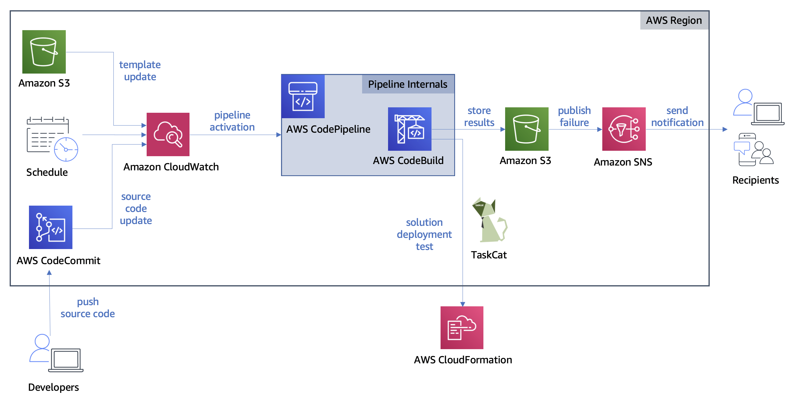
CloudFormation templates to be tested are stored in an Amazon S3 bucket. Custom test scripts and TaskCat deployment configuration are stored in an AWS CodeCommit repository.

The pipeline is triggered in one of three ways: an update to the CloudFormation Template in S3, an Amazon CloudWatch events rule, and an update to the testing source code repository. Once the pipeline has been triggered, AWS CodeBuild pulls the source code to deploy the CloudFormation template, test the deployed environment, and store the results in an S3 bucket. If any failures are discovered, subscribers to the failure topic are notified. The following diagram shows its overall architecture.

Diagram of Automated Testing Pipeline architecture

Diagram of Automated Testing Pipeline architecture

In order to create the Automated Testing Pipeline, two interns collaborated over the course of 5 weeks to produce the architecture and custom test scripts. We divided the work of constructing a serverless architecture and writing out test scripts for the output urls for OHDSI-on-AWS and REDCap environments on AWS.

The following tasks were completed to build out the Automated Testing Pipeline solution:

  • Setup AWS IAM roles for accessing AWS resources securely
  • Create CloudWatch events to trigger AWS CodePipeline
  • Setup CodePipeline and CodeBuild to run TaskCat and testing scripts
  • Configure TaskCat to deploy CloudFormation solutions in various AWS Regions
  • Write test scripts to interact with CloudFormation solutions’ deployed environments
  • Subscribe to receive emails detailing test results
  • Create a CloudFormation template for the Automated Testing Pipeline

The architecture can be extended to test any CloudFormation stack. For this particular use case, we wrote the test scripts specifically to test the urls output by the CloudFormation solutions. The Automated Testing Pipeline has the following features:

  • Deployed in a single AWS Region, with the exception of the tested CloudFormation solution
  • Has a serverless architecture operating at the AWS Region level
  • Deploys a pipeline which can deploy and test the CloudFormation solution
  • Creates CloudWatch events to activate the pipeline on a schedule or when the solution is updated
  • Creates an Amazon SNS topic for notifying subscribers when there are errors
  • Includes code for running TaskCat and scripts to test solution functionality
  • Built automatically in minutes
  • Low in cost with free tier benefits

The pipeline is triggered automatically when an event occurs. These events include a change to the CloudFormation solution template, a change to the code in the testing repository, and an alarm set off by a regular schedule. Additional events can be added in the CloudWatch console.

When the pipeline is triggered, the testing environment is set up by CodeBuild. CodeBuild uses a build specification file kept within our source repository to set up the environment and run the test scripts. We created a CodeCommit repository to host the test scripts alongside the build specification. The build specification includes commands run TaskCat — an open-source tool for testing the deployment of CloudFormation templates. TaskCat provides the ability to test the deployment of the CloudFormation solution, but we needed custom test scripts to ensure that we can interact with the deployed environment as expected. If the template is successfully deployed, CodeBuild handles running the test scripts against the CloudFormation solution environment. In our case, the environment is accessed via urls output by the CloudFormation solution.

We used a Selenium WebDriver for interacting with the web pages given by the output urls. This allowed us to programmatically navigate a headless web browser in the serverless environment and gave us the ability to use text output by JavaScript functions to understand the state of the test. You can see this interaction occurring in the code snippet below.

def log_in(driver, user, passw, link, btn_path, title):
    """Enter username and password then submit to log in

        :param driver: webdriver for Chrome page
        :param user: username as String
        :param passw: password as String
        :param link: url for page being tested as String
        :param btn_path: xpath to submit button
        :param title: expected page title upon successful sign in
        :return: success String tuple if log in completed, failure description tuple String otherwise
    """
    try:
        # post username and password data
        driver.find_element_by_xpath("//input[ @name='username' ]").send_keys(user)
        driver.find_element_by_xpath("//input[ @name='password' ]").send_keys(passw)

        # click sign in button and wait for page update
        driver.find_element_by_xpath(btn_path).click()
    except NoSuchElementException:
        return 'FAILURE', 'Unable to access page elements'

    try:
        WebDriverWait(driver, 20).until(ec.url_changes(link))
        WebDriverWait(driver, 20).until(ec.title_is(title))
    except TimeoutException as e:
        print("Timeout occurred (" + e + ") while attempting to sign in to " + driver.current_url)
        if "Sign In" in driver.title or "invalid user" in driver.page_source.lower():
            return 'FAILURE', 'Incorrect username or password'
        else:
            return 'FAILURE', 'Sign in attempt timed out'

    return 'SUCCESS', 'Sign in complete'

We store the test results in JSON format for ease of parsing. TaskCat generates a dashboard which we customize to display these test results. We are able to insert our JSON results into the dashboard in order to make it easy to find errors and access log files. This dashboard is a static html file that can be hosted on an S3 bucket. In addition, messages are published to topics in SNS whenever an error occurs which provide a link to this dashboard.

Dashboard containing descriptions of tests and their results

Customized TaskCat dashboard

In true CI/CD fashion, this end-to-end design automatically performs tasks that would otherwise be performed manually. We have shown how deploying solutions, testing solutions, notifying maintainers, and providing a results dashboard are all actions handled entirely by the Automated Testing Pipeline.

Getting Started with the Automated Testing Pipeline

Prerequisite tasks to complete before deploying the pipeline:

Once the prerequisite tasks are completed, the pipeline is ready to be deployed. Detailed information about deployment, altering the source code to fit your use case, and troubleshooting issues can be found at the GitHub page for the Automated Testing Pipeline.

For those looking to jump right into deployment, click the Launch Stack button below.

Button to click to deploy the Automated Testing Pipeline via CloudFormation

Tasks to complete after deployment:

  • Subscribe to SNS topic for error messages
  • Update the code to match the parameters and CloudFormation template that were chosen
  • Skip this step if you are testing OHDSI-on-AWS. Upload the desired CloudFormation template to the created source S3 Bucket
  • Push the source code to the created CodeCommit Repository

After the code is pushed to the CodeCommit repository and the CloudFormation template has been uploaded to S3, the pipeline will run automatically. You can visit the CodePipeline console to confirm that the pipeline is running with an “in progress” status.

You may desire to alter various aspects of the Automated Testing Pipeline to better fit your use case. Listed below are some actions you can take to modify the solution to fit your needs:

  • Go to CloudWatch Events and update rules for automatically started the pipeline.
  • Scale out testing by providing custom testing scripts or altering the existing ones.
  • Test a different CloudFormation template by uploading it to the source S3 bucket created and configuring the pipeline accordingly. Custom test scripts will likely be required for this use case.

Challenges Addressed by the Automated Testing Pipeline

The Automated Testing Pipeline directly addresses the challenges we faced with maintaining our OHDSI and REDCap solutions. Additionally, the pipeline can be used whenever there is a need to test CloudFormation templates that are being used on a regular basis or are distributed to other users. Listed below is the set of specific challenges we faced maintaining CloudFormation solutions and how the pipeline addresses them.

Table describing challenges faced with their direct solution offered by Testing Pipeline

The desire to better serve our customers guided our decision to create the Automated Testing Pipeline. For example, we know that source code used to build the OHDSI-on-AWS environment changes on occasion. Some of these changes have caused the environment to stop functioning correctly. This left us with cases where our customers had to either open an issue on GitHub or reach out to AWS directly for support. Our customers depend on OHDSI-on-AWS functioning properly, so fixing issues is of high priority to our team. The ability to run tests regularly allows us to take action without depending on notice from our customers. Now, we can be the first ones to know if something goes wrong and get to fixing it sooner.

“This automation will help us better monitor the CloudFormation-based projects our customers depend on to ensure they’re always in working order.” — James Wiggins, EDU HCLS SA Manager

Cleaning Up

If you decide to quit using the Automated Testing Pipeline, follow the steps below to get rid of the resources associated with it in your AWS account.

  • Delete CloudFormation solution root Stack
  • Delete pipeline CloudFormation Stack
  • Delete ATLAS S3 Bucket if OHDSI-on-AWS was chosen

Deleting the pipeline CloudFormation stack handles removing the resources associated with its architecture. Depending on the CloudFormation template chosen for testing, additional resources associated with it may need to be removed. Visit our GitHub page for more information on removing resources.

Conclusion

The ability to continuously test preexisting solutions on AWS has great benefits for our team and our customers. The automated nature of this testing frees up time for us and our customers, and the dashboard makes issues more visible and easier to resolve. We believe that sharing this story can benefit anyone facing challenges maintaining CloudFormation solutions in AWS. Check out the Getting Started with the Automated Testing Pipeline section of this post to deploy the solution.

Additional Resources

More information about the key services and open-source software used in our pipeline can be found at the following documentation pages:

About the Authors

Raleigh Hansen is a former Solutions Architect Intern on the Academic Medical Centers team at AWS. She is passionate about solving problems and improving upon existing systems. She also adores spending time with her two cats.

Dan Le is a former Solutions Architect Intern on the Academic Medical Centers team at AWS. He is passionate about technology and enjoys doing art and music.

Fundbox: Simplifying Ways to Query and Analyze Data by Different Personas

Post Syndicated from Annik Stahl original https://aws.amazon.com/blogs/architecture/fundbox-simplifying-ways-to-query-and-analyze-data-by-different-personas/

Fundbox is a leading technology platform focused on disrupting the $21 trillion B2B commerce market by building the world’s first B2B payment and credit network. With Fundbox, sellers of all sizes can quickly increase average order volumes (AOV) and improve close rates by offering more competitive net terms and payment plans to their SMB buyers. With heavy investments in machine learning and the ability to quickly analyze the transactional data of SMB’s, Fundbox is reimagining B2B payments and credit products in new category-defining ways.

Learn how how the company simplified the way different personas in the organization query and analyze data by building a self-service data orchestration platform. The platform architecture is entirely serverless, which simplifies the ability to scale and adopt to unpredictable demand. The platform was built using AWS Step Functions, AWS Lambda, Amazon API Gateway, Amazon DynamoDB, AWS Fargate, and other AWS Serverless managed services.

For more content like this, subscribe to our YouTube channels This is My Architecture, This is My Code, and This is My Model, or visit the This is My Architecture on AWS, which has search functionality and the ability to filter by industry, language, and service.
