Cloudflare’s AI Search combines Workers AI, Vectorize, R2, and Browser Run into a fully managed index and retrieval pipeline. Since we launched AI Search over a year ago, we’ve seen developers use it to power a wide range of search use cases, from searching internal documentation to powering search for their websites. We use AI Search ourselves to power search on our own blog and developer docs.
As part of general availability, we’ll start billing for AI Search on November 1, 2026, and continue to offer a generous free tier on all Workers plans.
New: multimodal embedding and retrieval
An image is more than the sentence used to describe it. Product texture, screenshot state, chart relationships, document layout, and fine visual detail can all disappear when pixels are compressed into a caption.
AI Search now preserves both signals: it embeds image pixels directly for visual retrieval while retaining captions for textual understanding. To keep these richer representations efficient, AI Search leverages Matryoshka Representation Learning (MRL), allowing smaller embeddings to retain useful information while keeping storage manageable and search fast.
Although we originally supported retrieval over images, the implementation was naive: we would perform object detection, generate a caption, and then embed that text. This made images searchable, but only through the details captured in the caption. Now, we do both — caption-based understanding and native image retrieval.
Native multimodal retrieval is available today with the Qwen3-VL-Embedding model. At query time, AI Search checks whether your instance’s embedding model supports images. If it does, a query image is embedded directly by that model, landing in the same vector space as your indexed images and text.
If your embedding model is text-only, you can still query with an image. AI Search converts the query image to text with ToMarkdown and searches using the resulting caption. This gives every model basic multimodal support, while models with native image support get the full visual signal.
Caption-based understanding
A small bird with black-and-white markings perched among golden fruit and green leaves
Native Image Retrieval
Can match details omitted from the caption: the geometry of the bird’s white eyebrow stripe, its yellow-green plumage, the mixture of smooth and weathered fruit, the leaves’ deeply ribbed texture, and the image’s warm palette and shallow-focus composition.
The caption is a compressed interpretation of the image. Capturing every potentially useful detail requires long or specialized captions, written with the eventual search query in mind. Native image embeddings preserve visual characteristics without requiring the caption to anticipate which details matter.
This enables searches that are difficult to express precisely with words. You can describe an image you want to find, provide another image to locate visually similar results, or combine both, such as “a bird with similar markings” or “a bird perched on a leafy branch with plums.” It is useful for product discovery, screenshot matching, charts, diagrams, scanned documents, and other collections where color, texture, composition, or spatial relationships matter.
Here’s how a query moves through AI Search. First, the query is optionally rewritten, then embedded (image queries are embedded directly by multimodal models, or captioned first by text-only models). Vector and keyword search run in parallel, and results are fused and optionally reranked. The top chunks are returned, or passed to a generation model to write an answer.
Bigger files and OCR for scanned documents
AI Search now accepts your text files (Markdown, HTML, CSV, JSON and similar) and PDFs up to 10 MiB, up from 4 MiB. Many PDFs are really scanned images with no extractable text. For those, turn on OCR and AI Search reads the text from each page before chunking and embedding it. OCR is available to every account and is billed under the new AI Search pricing as image processing ingestion tokens.
Now in GA: billing and pricing for AI Search
During our August 2026 Agents Week, we announced preview pricing for AI Search. With the product going GA today, we’re announcing billing for AI Search that is going live on November 1, 2026. We’ll send a reminder email before billing is enabled.
AI Search pricing is designed, so you can estimate your bill before you index a single file. You pay for three things: the content you ingest, the data you store, and the queries you run. The work in between (parsing, chunking, embedding with Workers AI models, keyword indexing, and reranking) is included. There are no instance hours, capacity units, or monthly minimums to size up front, and small projects fit inside the free monthly allotment.
Ingestion pricing is based on one rate per token with whichever Workers AI embedding model you pick, and tokens are counted the same way for every model. Switching from a text-only embedding model to a multimodal one doesn't change what you pay to ingest, unless you are also processing images (add-on fee). Storage is priced on the size of data in your indices. Querying is priced based on the type of query (semantic vs. full-text) and how many queries you send.
Estimating your cost comes down to how much content you index, how much you store, and how many queries you expect. Here's the pricing we announced in preview, with one tweak that we’re making: on the free monthly allotment, you will receive 1,000 semantic queries and 1,000 full-text queries (instead of a shared pool of 2,000 queries).
Pricing
Free monthly allotment (all Workers plans)
Ingestion
Base Ingestion
$0.75 / 1M tokens
5M tokens †
Image processing (add-on)
+$0.50 / 1M tokens
5M tokens †
Storage
Stored data
$2.00 / GB-month
10 GB
Query
Semantic (hybrid and vector search)
$0.75 / 1k queries
1,000 queries
Full-text
$0.10 / 1k queries
1,000 queries
Embedding and Reranking
Ingestion and query
Free with select Workers AI models; third-party billed separately
N/A
† A single pool of 5M ingestion tokens per month, covering any file type currently supported (e.g., text, images).
What’s next
Multimodal embedding support is just the first step; we’re building an ingestion pipeline to support full video and audio processing to allow our customers to search their rich media assets.
We’re also refactoring the keyword search engine so that it scales better with your content requirements, particularly for when you have big data stores where the current implementation has limits.
Finally, we’re developing better and simpler ways to enable AI Search and create indexes for websites already running on Cloudflare. This ensures AI agents can discover, explore, and consume content more easily and efficiently.
Stay tuned for these follow-up announcements and more.
AI Search is now generally available to enable and use today. Get started with our new multimodal embeddings, bigger files, OCR features, and our new managed instance pricing. Check out the AI Search developer docs for more information.
During Birthday Week 2025, we announced the Cloudflare Data Platform, a suite of products that ingest, store, and query your analytical data. Today, we’re announcing that the platform is generally available, and we’re giving it a new name: Cloudflare Basin.
Basin is a serverless data analytics platform built on Apache Iceberg, the open standard for data lakes, and R2 Object Storage. The Basin family includes:
Basin Pipelines, formerly Cloudflare Pipelines, receives events from Workers, HTTP, or Cloudflare Logpush, transforms them with SQL, and writes them as Apache Iceberg tables or files in R2.
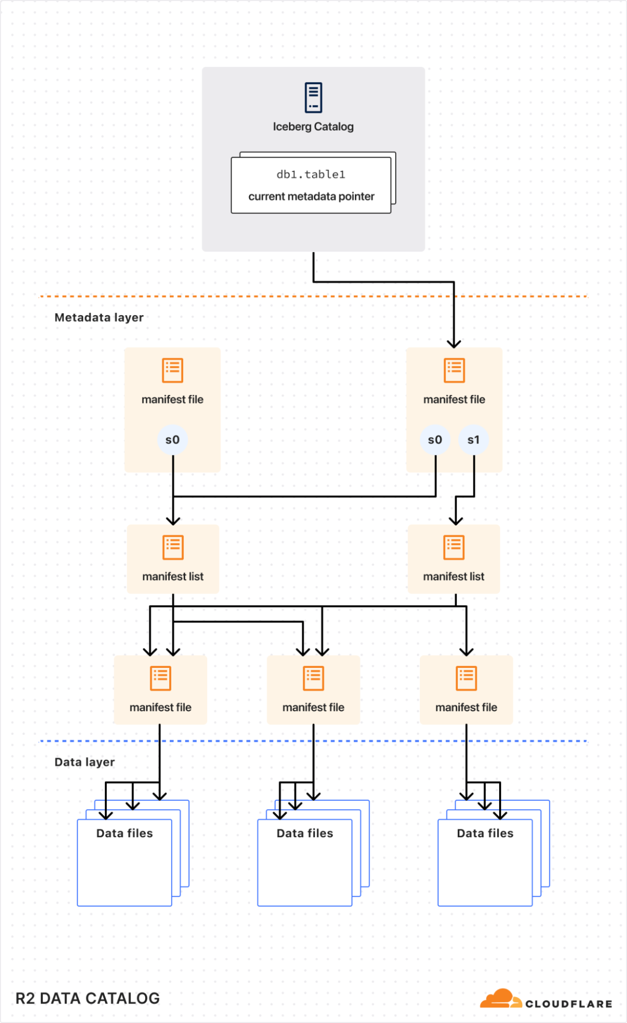
Basin Catalog, formerly R2 Data Catalog, manages Iceberg metadata and automatically maintains tables to keep them fast and cost-efficient.
Basin SQL, formerly R2 SQL, is our serverless, distributed SQL engine for querying Apache Iceberg tables directly on Cloudflare.
Basin brings an end-to-end analytics platform to the Developer Platform, enabling you to collect data from a variety of sources, such as apps, infrastructure, devices, and other Cloudflare services, then query it to answer analytical questions.
We set out to build a data platform last year when we saw two fundamental developments that changed how modern data applications were being built. First, Apache Iceberg emerged as the standard open table format, making data portable across nearly every major query engine. Second, we started seeing developers bring their analytics data to R2 where the lack of egress charges made it practical and cost-efficient to actually access their data from different tools, teams, regions, and cloud providers.
So, when we launched Basin in open beta, developers — including our billing and infrastructure teams at Cloudflare — immediately started adopting these services for a variety of use cases including using real-time data to optimize e-commerce sites, long-term storage and reporting of billing metrics, and ingesting and querying telemetry from Cloudflare’s infrastructure to measure and improve utilization and efficiency.
“We moved our entire company's data pipeline to Basin Pipelines, Catalog, and SQL, replacing a complex AWS S3 and Athena setup with a cleaner, serverless architecture that reliably handles all of our event data. -Dax Raad, Co-Founder, Anomaly
Our early adopters taught us a great deal about what it means to run an analytics platform on the edge. We spent the past year improving Basin around three specific areas that hone in on what makes analytics in Developer Platform unique: speed, openness, and cost efficiency.
Basin is built for speed — whether it’s about getting started or executing large queries. You can create a Basin Catalog, set up a Pipeline to ingest data, and query it with Basin SQL in seconds. This matters as we see more data applications being built from prompts to coding agents, which would otherwise have to wait and poll for resources or data. As datasets grow, Basin Catalog compacts metadata and data files to reduce I/O and generates statistics for query planning. Basin SQL uses those statistics to split queries into smaller tasks and distribute them across Workers, keeping queries fast and consistent as datasets scale.
A large driving force in the development and adoption of Basin is the continued growth we are seeing in the open Apache Iceberg ecosystem. Developers have been rallying around the radical idea that you should own and be in control of your own data — separating the storage layer from the compute layer and allowing you to use the right query engine for the job. With Basin, you can read and write your data using any Iceberg-compatible engine, including PyIceberg, DuckDB, Snowflake, and Apache Spark. That kind of data portability is only possible with free egress, which allows developers to access their data in Cloudflare from the wide variety of tools in the ecosystem, regardless of region or cloud.
“Bobsled is a data product platform that the world's most advanced data teams use to build and distribute AI-ready data to partners, vendors and customers," said Julien Grobbelaar, Head of Platform at Bobsled. "Basin allows us to build data products that can be made accessible in any region of every major data and AI platform, all at production-grade reliability and a fraction of the cost thanks to zero egress fees.”
In addition to free egress, our serverless architecture allows us to offer further cost efficiencies to our customers with usage-based pricing. You are only billed when Basin ingests, processes, or queries your data. Developers can build out analytics for hobby projects at little to no cost, while our pricing scales economically for larger enterprise use cases. There are no hourly charges or separate infrastructure costs to worry about.
If you are ready to get started, refer to the Basin tutorial for a step-by-step guide on how to use Basin Pipelines to deliver events to an Apache Iceberg table managed by Basin Catalog, and query them with Basin SQL. Read on to learn more about Basin and where we are going next.
Why Basin?
We launched these products last year as the Cloudflare Data Platform, which has served us well for the first year of availability. For our GA launch, we decided we needed a new name that encompasses our ambitions for the platform, links together all the products, and is a bit punchier.
A basin is where rivers from many sources come together to a single point. We felt that Basin perfectly captures how the platform is used: Pipelines brings data into Basin Catalog while Basin SQL makes it instantly queryable. A fun fact: roughly 20% of Earth’s land drains into endorheic basins, much like over 20% of the web sits behind Cloudflare’s network.
Today, Basin is made up of three products: Pipelines, Catalog, and SQL, covering ingestion, storage, and querying, and will expand over time with more products managing the rest of the analytical data lifecycle.
Basin Pipelines
Before you can query your data, your events need to be ingested, structured to a schema, and written to object storage. This is the role of Basin Pipelines. It accepts events through HTTP endpoints or Workers bindings, processes them according to a SQL query, and delivers them to Basin Catalog as Apache Iceberg tables or R2 as JSON or Parquet files.
Since our beta launch, users have created tens of thousands of Pipelines for a wide variety of use cases. For example, a common pattern we see is using Pipelines to transform Cloudflare HTTP logs before storing them:
Doing this work during ingestion can significantly reduce the storage footprint, reduce noise from dynamic data sources, and can help prevent sensitive or unnecessary values from being written.
Since the beta, we have greatly expanded the scalability of Pipelines: we now support ingesting up to 3GB/s per stream. We’ve also expanded the feature set and integration with other Cloudflare systems:
Cloudflare Logpush integration: you can transform Cloudflare logs with SQL and store them as compressed Parquet files or Iceberg tables, ready to query with Basin SQL or another engine.
Worker bindings are schema-aware. Running wrangler types generates TypeScript types from a stream's schema, catching missing fields and type mismatches before deployment.
Data quality errors are visible. The dashboard and GraphQL API surface dropped events and distinguish missing fields, type mismatches, parse failures, and null values.
The entire ingestion path can be infrastructure as code. Terraform resources cover the catalog, stream, sink, and the SQL that connects them.
Next we plan to expand Pipelines capabilities even further, including:
Custom partitioning when writing to Basin Catalog
Schema migrations, and updatable configuration and Pipelines SQL
Support for Iceberg V3, including the Variant type for efficient querying of semi-structured data
Stateful processing to support workloads such as streaming aggregations, joins, and incrementally updated materialized views
Basin Catalog
Basin Catalog was the first product we launched in the family last year. Since then, we’ve seen thousands of developers use Basin Catalog for simple use cases such as giving DuckDB a structured way to access analytics data in R2, all the way to developers building complete enterprise data sharing platforms, fully taking advantage of zero egress fees and easy-to-use APIs.
Basin Catalog is the easiest way to get started with Apache Iceberg. Just run:
You instantly get a fully managed Apache Iceberg REST catalog that automatically performs routine maintenance required to keep those tables performant and healthy.
When we announced the Data Platform, Basin Catalog had just added automatic compaction. Since then, it has evolved to maintain healthy tables as your data scales:
Per-table compaction policies let you choose target file sizes based on each table's access pattern.
Automatic snapshot expiration removes old Iceberg snapshots according to a retention policy, while preserving a minimum number of recent snapshots.
Unreferenced data-file cleanup reclaims storage when snapshots expire, without requiring a separate Spark maintenance job.
Manifest optimization consolidates and clusters fragmented manifests by partition before compaction, reducing metadata I/O during query planning.
We have some exciting features in the works for Basin Catalog including:
A new way for compaction to efficiently sort and cluster data for improved query performance
More granular auth controls for namespaces and tables
Jurisdiction support to adhere to data sovereignty and compliance requirements
Basin SQL
Basin SQL is our serverless, distributed query engine for Apache Iceberg tables stored in Basin Catalog. It’s designed for reading large datasets and automatically scales across Cloudflare's global network. There are no clusters or resources to provision, just a readily available API for you and your agents to immediately start querying your data.
At beta launch, Basin SQL was great at filtering and exploring large event and time-series tables. Over the last year, Basin SQL has evolved to support hundreds of functions including:
Standard and approximate aggregations, GROUP BY, HAVING, and schema-discovery commands
More than 190 scalar and aggregate functions across strings, timestamps, regular expressions, cryptography, statistics, arrays, maps, and structs
CASE expressions, common table expressions, casting, arithmetic, and EXPLAIN
Inner, outer, semi, and anti joins; subqueries; self-joins; and multi-table queries
DISTINCT, UNION, INTERSECT, and EXCEPT
Window functions, QUALIFY, grouping sets, rollups, and cubes
A suite of JSON functions
Suppose your Pipeline delivers application events into one table and account data into another. You can now join those tables, aggregate activity by customer, rank the results with a window function, and filter the ranking in one query:
You can run Basin SQL from Wrangler or the API, or open the built-in editor in the Cloudflare dashboard. The editor provides syntax highlighting and autocomplete, a browser for namespaces and tables, query statistics and plans, and exportable results. It makes the path from a new table to a useful answer a matter of seconds.
The team isn’t stopping here and is currently working on:
Advanced statistics and adaptive scheduling to improve performance and efficiency of queries
Full data definition language (DDL) support directly from Basin SQL
Iceberg V3 support including support for the VARIANT and geospatial types
What comes next
Our future vision is that data infrastructure is completely abstracted away. Storage formats, products, and resources are just implementation details — important ones that help enable the important outcomes — but tend to get in the way. We’re building towards a platform where developers start with questions rather than CREATE statements or CLI commands. We’ve laid the foundation for that vision, and now we’re building towards that vision including:
Support for the latest Apache Iceberg spec across the entire platform, unlocking more flexible ways to use your data
Push-button ingestion sources and destinations, with zero-configuration connections across Cloudflare's developer and observability products
Advanced adaptive table-maintenance strategies in Basin Catalog that automatically organize data around real query patterns
Continued expansion of SQL compatibility, performance, and observability for increasingly complex analytical workloads
More ways to continuously process data in real-time and trigger actions based on the signals within the data
Tools for adhering to data compliance and sovereignty rules across the platform
We will continue to build with open standards: using open formats and protocols, contributing improvements to the projects we depend on, and making sure your data remains available to the broader ecosystem.
Get started
Basin Pipelines, Basin Catalog, and Basin SQL are generally available today. You can use them together as an end-to-end platform or adopt the parts that fit your existing architecture.
Follow the getting started tutorial to ingest events, create an Apache Iceberg table in Basin Catalog, and query it with Basin SQL. Visit the Basin documentation for product guides, pricing, limits, and integrations.
Existing Cloudflare Pipelines, R2 Data Catalog, and R2 SQL configurations will continue to work.
As of June 23, 2026, cdnjs, one of the Internet's busiest open-source CDNs, is running exclusively on Cloudflare’s Developer Platform. Along the way, cdnjs surfaced limits in the platform, and the platform grew to meet them.
cdnjs is a free, open-source content delivery network for JavaScript and CSS libraries. Instead of using a bundler or self-hosting jQuery, Bootstrap, or Lodash, you drop a <script> tag pointing to cdnjs.cloudflare.com and the library loads from Cloudflare's edge, instantly, anywhere in the world, with no signup, no API keys, and no rate limits. It's the infrastructure behind a significant portion of “intro to JavaScript” tutorials, CodePen demos, and Stack Overflow answers.
Community-driven, cdnjs is used on roughly 12% of all websites, a 48.3% share of the JavaScript CDN market. It serves an average of 108,000 requests per second, 9 billion per day, across more than 330 Cloudflare data centers, with a 98.6% cache hit rate. Pretty cool, Internet!
In 2011, when bundlers were exotic, npm was barely a year old, and "just drop a <script> tag" was how the web shipped JavaScript, Ryan Kirkman and Thomas Davis built cdnjs as a free, community-run mirror of every popular open-source library.
Cloudflare stepped in to host it free of charge months later, and took over project maintenance in 2019. Back then, Cloudflare didn't have a mature Developer Platform that could fully sustain the entire cdnjs ecosystem. Fifteen years and a lot of building blocks later, the platform is mature enough to run cdnjs end to end, on Workers, Workflows, D1, Queues, Workers Cache, R2, KV, and Containers.
Why cdnjs has 9 billion requests a day
The web has changed beyond recognition from those days. We have ES Modules (ESM), the standardized import / export syntax browsers understand natively. We have import maps, Vite, Bun, Turbopack. We have AI assistants that scaffold entire apps in seconds. Bundlers are everywhere. So why does a CDN for <script> tags still serve 9 billion requests a day?
One reason: LLMs love cdnjs. When ChatGPT, Claude, or Cursor scaffold a quick HTML demo, they reach for cdnjs because their training data is full of it. There have been 15 years of blog posts, GitHub READMEs, tutorial sites, and Q&A threads pointing to cdnjs.cloudflare.com. The URL pattern is consistent and versions are immutable — exactly the kind of dependency a model can produce reliably without hallucinating.
Every file on cdnjs has an SRI hash (we're still working on ensuring all the existing stored hashes match reality due to bugs in the old system), mirrors are auditable, and the whole project is open source. In a world increasingly worried about supply-chain attacks, an immutable, hash-verified mirror of well-known libraries is indispensable.
And it's free, forever, for everyone. No API keys. No rate limits. No "sign up to continue." That's a rare thing on today's Internet, and it's worth protecting.
Why we migrated
We didn't migrate because cdnjs was slow. We migrated because we want to keep improving it.
The previous architecture served users well: 98% cache hit, billions of requests, no outages. But internally, shipping anything new or fixing existing issues in how packages were processed was getting harder. Making a change meant coordinating deployments across GCP Functions, a VM, and Cloudflare. Observability was painful too.
The pain points
In 2020, we migrated cdnjs to serverless, moving file serving onto Cloudflare Workers and KV, with a bare-metal origin as fallback. That change dramatically improved resilience and scalability, and let us pre-compress every asset with Brotli and gzip for smaller, faster responses, but only on the serving side.
The publishing side — the pipeline that watches npm and GitHub for new library versions, downloads them, processes them, and writes the results so cdnjs can serve them — stayed on Google Cloud Platform (GCP). At the time, Cloudflare Workers were designed for fast, short-lived HTTP requests; they didn't yet have the building blocks for a long-running, multi-step pipeline that fetches large tarballs, runs CPU-heavy compression, and orchestrates work over hours. Workflows, Queues, Durable Objects, R2, and Containers didn't exist yet.
So we built the publishing bot on what was available: a chain of GCP Functions, a VM running git-sync, and a GitHub repository as the source of truth. It worked, but six years later, that architecture was showing its age. Here's a diagram of the previous architecture:
The architecture had five pain points. The one that hurt most was observability: debugging meant stitching logs together by hand. We'll start there.
No shared trace A single package update could pass through Cloud Functions, Google Cloud Storage (GCS) object events, Pub/Sub topics, a git-sync VM, and Workers KV before a file reached a user. None of those systems shared a correlation ID. GCP Logging held one half of the story, Cloudflare Logpush held the other, and the two had no common key to join on.
The problem wasn't outright failure, it was partial success. A version that processed cleanly, wrote to KV, and then silently failed to land in the GitHub repo would serve fine for weeks until someone noticed the two stores had diverged. There was no alert for that. There couldn't be, because nothing in the system knew the full pipeline state.
Split-brain storage Files lived in two places at once: Workers KV at the edge (with a bare-metal origin as fallback) and a GitHub repository as the source of truth. The ingestion pipeline wrote to both at the end of every run. Neither was authoritative, and when they drifted, there was no clean way to reconcile them.
Pipeline glued together with object events The ingestion pipeline was a chain of small GCP Cloud Functions, each doing one step and handing off to the next through shared storage. One function fetched the package's release archive from npm and dropped it in a bucket. The bucket firing a "new file" event triggered the next function, which unpacked it and wrote the results somewhere else, triggering the next, and so on. Storage was doing double duty as a message queue, with no dead-letter queue, no backlog visibility, and no clean replay when a step failed.
26 functions for 26 letters Just checking npm for updates required 26 Cloud Functions, one per letter of the alphabet. Each shard had its own deployment and its own logs, and the only way to know if the fleet was healthy was to check all 26.
The GitHub repo GitHub couldn't serve A separate VM ran git-sync, mirroring every processed file into cdnjs/cdnjs. Years of releases pushed it past 1.1TB of packed storage, large enough that GitHub's own archive service refused to generate tarballs or zip downloads for it. Forking became impractical, clones were slow, and the .gitignore had grown to 274 hand-curated entries blocking broken or weirdly-versioned releases. It was a documented graveyard of everything the pipeline couldn't reasonably reject upstream.
A genuine thank you to the GitHub team for hosting this giant for over a decade. They bore with us through years of storage growth, and the project wouldn't have survived without them.
A quieter benefit that came with the migration is having fewer moving parts to secure. Cloud Functions, a git-sync VM, container images, GCS buckets, service-account keys — every one of those was a thing to secure, patch, and audit. Retiring the pipeline closed all of the recently opened cdnjs vulnerabilities.
How we re-built it
The new cdnjs architecture runs entirely on Cloudflare’s Developer Platform.
R2 is the single source of truth for file content. It has no practical size limit, so the files that couldn't fit in KV before, like source maps, big bundles, and font packs, now live alongside everything else. As a bonus, the S3 API makes the entire cdnjs catalog accessible to any S3 client. Maintain a mirror? Open an issue on the cdnjs repository and we'll set you up with read-only credentials.
KV stores only metadata now: package info, version lists, SRI hashes. KV is built for high read volume with infrequent writes, which is exactly the shape of metadata access.
In front of the Worker sits Workers Cache, a tiered cache Cloudflare launched this year. Before, we relied on a separate internal caching layer between the edge and the Worker. That layer is gone now, replaced by one owned by the Developer Platform, the same platform that runs the rest of cdnjs. One less moving part!
The new architecture also extends a long-standing partnership. DigitalOcean has hosted the cdnjs website for years as a sponsor; now it hosts the storage too. Every file published to R2 is mirrored to DigitalOcean Spaces: architecturally a disaster-recovery copy, operationally also a live fallback. The serving worker reads through to it whenever R2 can’t return a file. The chain is cache → R2 → DigitalOcean, so R2 having a bad day doesn't take cdnjs down. A Cloudflare-hosted origin still sits in the chain during the transition, but it will retire once the GitHub backfill lands in R2.
The ingestion pipeline is built on Cloudflare Workflows. Every ten minutes, a cron job triggers PackageUpdatesWorkflow, which checks npm and GitHub for new versions. For each new version found, it spawns a DownloadPackageWorkflow that fetches the tarball into R2, then a ProcessingWorkflow per file that extracts, minifies, and compresses. Finally, PublishingWorkflow writes the results to R2 and KV and updates the Algolia search index.
Because Workflows provides durable execution, the state of each step is preserved. If anything fails — a network timeout, a compression error — the workflow resumes from the last successful step.
The trickier piece is how we glue Workflows to the external compression container. We pre-compress text-based files to streamline the delivery process. But compression is too CPU-intensive for a Worker, so we hand it off to Cloudflare Containers, wait for compression to complete, and then pick up where we left off.
The pipeline has two kinds of waiting:
Per file: Each ProcessingWorkflow writes the uncompressed file to an R2 bucket, sends a job to a Queue, and hibernates. A Rust compression service running in the container picks it up, compresses it, and writes the result to another bucket. An R2 event notification wakes the workflow up so it can continue.
Per package: The parent workflow needs to wait for all its file children before moving on to publish. A package with thousands of files means thousands of children running in parallel. We use a small Durable Object as a counter: a parent increments on each child it spawns, children decrement when they finish. The parent wakes up when the counter reaches zero.
An overview of the new architecture, with R2 as the source of truth and Workflows running the pipeline:
Pushing the limits
Designing the new architecture was one challenge. Migrating the existing catalog into it, without disturbing a single file already in the wild, was another.
We'd actually tried this once before and had to roll back. The plan, back then, was to re-process old packages and write the results directly to R2, but the regenerated files didn't byte-match what KV had been serving. Minifiers and compressors aren't fully deterministic across versions, so the new outputs were correct but had different SRI hashes. For a CDN where users pin those hashes in their HTML, that's a serving break. So we rolled back, and now, we migrated the existing content from KV to R2 as-is instead of regenerating it.
That decision shifted the problem from "re-process millions of files" to "copy millions of files between accounts, without missing any." And that's where we ran into the Workers subrequest limit, capped at 1,000 per invocation on paid plans. A package with thousands of files would burn through it in one go. Parallelizing didn't help, since every Worker hits the same ceiling. So we sharded the migration by package name and fanned the work out across many invocations via Queues, whose at-least-once delivery guarantee meant no package could silently fall out of the migration.
We hit two platform limits during the migration: 1,000 subrequests per Worker invocation and 1,024 steps per Workflow. Instead of just working around them, we asked the Workers and Workflows teams to raise them — which they did. Subrequests now go up to 10 million on paid plans; Workflows now default to 10,000 steps, configurable to 25,000.
The cdnjs pipeline runs on the same building blocks anyone can use: Workers, Workflows, R2, KV, Queues, Containers, and Durable Objects. The limits we hit are limits we lifted for everyone. If the Cloudflare Developer Platform can serve 9 billion requests a day and publish packages with hundreds of thousands of compressed, minified files, it can probably run whatever you're building.
What’s next
There's an obvious next question hiding in all of this: could cdnjs also serve modern, browser-native ES modules? The same packages, transformed on publish, ready to import without a bundler. The architecture doesn't rule it out. The Workflows-plus-Containers pattern that pre-compresses files today would work just as well for transforming them. We're not committing to it, but it's the kind of thing that's now possible to consider, which wasn't true a year ago.
git commit -m "with love" --author="cdnjs team"
We follow every open issue on GitHub and we want your feedback. Don't hesitate to contribute and help make the Internet better for everyone.
In the world of cybersecurity, a single data point is rarely the whole story. Modern attackers don’t just knock on the front door; they probe your APIs, flood your network with “noise” to distract your team, and attempt to slide through applications and servers using stolen credentials.
To stop these multi-vector attacks, you need the full picture. By using Cloudflare Log Explorer to conduct security forensics, you get 360-degree visibility through the integration of 14 new datasets, covering the full surface of Cloudflare’s Application Services and Cloudflare One product portfolios. By correlating telemetry from application-layer HTTP requests, network-layer DDoS and Firewall logs, and Zero Trust Access events, security analysts can significantly reduce Mean Time to Detect (MTTD) and effectively unmask sophisticated, multi-layered attacks.
Read on to learn more about how Log Explorer gives security teams the ultimate landscape for rapid, deep-dive forensics.
The flight recorder for your entire stack
The contemporary digital landscape requires deep, correlated telemetry to defend against adversaries using multiple attack vectors. Raw logs serve as the “flight recorder” for an application, capturing every single interaction, attack attempt, and performance bottleneck. And because Cloudflare sits at the edge, between your users and your servers, all of these events are logged before the requests even reach your infrastructure.
Cloudflare Log Explorer centralizes these logs into a unified interface for rapid investigation.
Log Types Supported
Zone-Scoped Logs
Focus: Website traffic, security events, and edge performance.
HTTP Requests
As the most comprehensive dataset, it serves as the “primary record” of all application-layer traffic, enabling the reconstruction of session activity, exploit attempts, and bot patterns.
Firewall Events
Provides critical evidence of blocked or challenged threats, allowing analysts to identify the specific WAF rules, IP reputations, or custom filters that intercepted an attack.
DNS Logs
Identify cache poisoning attempts, domain hijacking, and infrastructure-level reconnaissance by tracking every query resolved at the authoritative edge.
NEL (Network Error Logging) Reports
Distinguish between a coordinated Layer 7 DDoS attack and legitimate network connectivity issues by tracking client-side browser errors.
Spectrum Events
For non-web applications, these logs provide visibility into L4 traffic (TCP/UDP), helping to identify anomalies or brute-force attacks against protocols like SSH, RDP, or custom gaming traffic.
Page Shield
Track and audit unauthorized changes to your site’s client-side environment such as JavaScript, outbound connections.
Zaraz Events
Examine how third-party tools and trackers are interacting with user data, which is vital for auditing privacy compliance and detecting unauthorized script behaviors.
Account-Scoped Logs
Focus: Internal security, Zero Trust, administrative changes, and network activity.
Access Requests
Tracks identity-based authentication events to determine which users accessed specific internal applications and whether those attempts were authorized.
Audit Logs
Provides a trail of configuration changes within the Cloudflare dashboard to identify unauthorized administrative actions or modifications.
CASB Findings
Identifies security misconfigurations and data risks within SaaS applications (like Google Drive or Microsoft 365) to prevent unauthorized data exposure.
Magic Transit / IPSec Logs
Helps network engineers perform network-level (L3) monitoring such as reviewing tunnel health and view BGP routing changes.
Browser Isolation Logs
Tracks user actions inside an isolated browser session (e.g., copy-paste, print, or file uploads) to prevent data leaks on untrusted sites
Device Posture Results
Details the security health and compliance status of devices connecting to your network, helping to identify compromised or non-compliant endpoints.
DEX Application Tests
Monitors application performance from the user’s perspective, which can help distinguish between a security-related outage and a standard performance degradation.
DEX Device State Events
Provides telemetry on the physical state of user devices, useful for correlating hardware or OS-level anomalies with potential security incidents.
DNS Firewall Logs
Tracks DNS queries filtered through the DNS Firewall to identify communication with known malicious domains or command-and-control (C2) servers.
Email Security Alerts
Logs malicious email activity and phishing attempts detected at the gateway to trace the origin of email-based entry vectors.
Gateway DNS
Monitors every DNS query made by users on your network to identify shadow IT, malware callbacks, or domain-generation algorithms (DGAs).
Gateway HTTP
Provides full visibility into encrypted and unencrypted web traffic to detect hidden payloads, malicious file downloads, or unauthorized SaaS usage.
Gateway Network
Tracks L3/L4 network traffic (non-HTTP) to identify unauthorized port usage, protocol anomalies, or lateral movement within the network.
IPSec Logs
Monitors the status and traffic of encrypted site-to-site tunnels to ensure the integrity and availability of secure network connections.
Magic IDS Detections
Surfaces matches against intrusion detection signatures to alert investigators to known exploit patterns or malware behavior traversing the network.
Network Analytics Logs
Provides high-level visibility into packet-level data to identify volumetric DDoS attacks or unusual traffic spikes targeting specific infrastructure.
Sinkhole HTTP Logs
Captures traffic directed to “sinkholed” IP addresses to confirm which internal devices are attempting to communicate with known botnet infrastructure.
WARP Config Changes
Tracks modifications to the WARP client settings on end-user devices to ensure that security agents haven’t been tampered with or disabled.
WARP Toggle Changes
Specifically logs when users enable or disable their secure connectivity, helping to identify periods where a device may have been unprotected.
Zero Trust Network Session Logs
Logs the duration and status of authenticated user sessions to map out the complete lifecycle of a user’s access within the protected perimeter.
Log Explorer can identify malicious activity at every stage
Get granular application layer visibility with HTTP Requests, Firewall Events, and DNS logs to see exactly how traffic is hitting your public-facing properties.Track internal movement with Access Requests, Gateway logs, and Audit logs. If a credential is compromised, you’ll see where they went. Use Magic IDS and Network Analytics logs to spot volumetric attacks and “East-West” lateral movement within your private network.
Identify the reconnaissance
Attackers use scanners and other tools to look for entry points, hidden directories, or software vulnerabilities. To identify this, using Log Explorer, you can query http_requests for any EdgeResponseStatus codes of 401, 403, or 404 coming from a single IP, or requests to sensitive paths (e.g. /.env, /.git, /wp-admin).
Additionally, magic_ids_detections logs can also be used to identify scanning at the network layer. These logs provide packet-level visibility into threats targeting your network. Unlike standard HTTP logs, these logs focus on signature-based detections at the network and transport layers (IP, TCP, UDP). Query to discover cases where a single SourceIP is triggering multiple unique detections across a wide range of DestinationPort values in a short timeframe. Magic IDS signatures can specifically flag activities like Nmap scans or SYN stealth scans.
Check for diversions
While the attacker is conducting reconnaissance, they may attempt to disguise this with a simultaneous network flood. Pivot to network_analytics_logs to see if a volumetric attack is being used as a smokescreen.
Identify the approach
Once attackers identify a potential vulnerability, they begin to craft their weapon. The attacker sends malicious payloads (e.g. SQL injection or large/corrupt file uploads) to confirm the vulnerability. Review http_requests and/or fw_events to identify any Cloudflare detection tools that have triggered. Cloudflare logs security signals in these datasets to easily identify requests with malicious payloads using fields such as WAFAttackScore, WAFSQLiAttackScore, FraudAttack, ContentScanJobResults, and several more. Review our documentation to get a full understanding of these fields. The fw_events logs can be used to determine whether these requests made it past Cloudflare’s defenses by examining the action, source, and ruleID fields. Cloudflare’s managed rules by default blocks many of these payloads by default. Review Application Security Overview to know if your application is protected.
Showing the Managed rules Insight that displays on Security Overview if the current zone does not have Managed Rules enabled
Audit the identity
Did that suspicious IP manage to log in? Use the ClientIP to search access_requests. If you see a “Decision: Allow” for a sensitive internal app, you know you have a compromised account.
Stop the leak (data exfiltration)
Attackers sometimes use DNS tunneling to bypass firewalls by encoding sensitive data (like passwords or SSH keys) into DNS queries. Instead of a normal request like google.com, the logs will show long, encoded strings. Look for an unusually high volume of queries for unique, long, and high-entropy subdomains by examining the fields: QueryName: Look for strings like h3ldo293js92.example.com, QueryType: Often uses TXT, CNAME, or NULL records to carry the payload, and ClientIP: Identify if a single internal host is generating thousands of these unique requests.
Additionally, attackers may attempt to leak sensitive data by hiding it within non-standard protocols or by using common protocols (like DNS or ICMP) in unusual ways to bypass standard firewalls. Discover this by querying the magic_ids_detections logs to look for signatures that flag protocol anomalies, such as “ICMP tunneling” or “DNS tunneling” detections in the SignatureMessage.
Whether you are investigating a zero-day vulnerability or tracking a sophisticated botnet, the data you need is now at your fingertips.
Correlate across datasets
Investigate malicious activity across multiple datasets by pivoting between multiple concurrent searches. With Log Explorer, you can now work with multiple queries simultaneously with the new Tabs feature. Switch between tabs to query different datasets or Pivot and adjust queries using filtering via your query results.
When you correlate data across multiple Cloudflare log sources, you can detect sophisticated multi-stage attacks that appear benign when viewed in isolation. This cross-dataset analysis allows you to see the full attack chain from reconnaissance to exfiltration.
Session hijacking (token theft)
Scenario: A user authenticates via Cloudflare Access, but their subsequent HTTP_request traffic looks like a bot.
Step 1: Identify high-risk sessions in http_requests.
SELECT RayID, ClientIP, ClientRequestUserAgent, BotScore
FROM http_requests
WHERE date = '2026-02-22'
  AND BotScore < 20
LIMIT 100
Step 2: Copy the RayID and search access_requests to see which user account is associated with that suspicious bot activity.
SELECT Email, IPAddress, Allowed
FROM access_requests
WHERE date = '2026-02-22'
  AND RayID = 'INSERT_RAY_ID_HERE'
Post-phishing C2 beaconing
Scenario: An employee clicked a link in a phishing email which resulted in compromising their workstation. This workstation sends a DNS query for a known malicious domain, then immediately triggers an IDS alert.
Step 1: Find phishing attacks by examining email_security_alerts for violations.
SELECT Timestamp, Threatcategories, To, Alertreason
FROM email_security_alerts
WHERE date = '2026-02-22'
  AND Threatcategories LIKE 'phishing'
Step 2: Use Access logs to correlate the user’s email (To) to their IP Address.
SELECT Email, IPAddress
FROM access_requests
WHERE date = '2026-02-22'
Step 3: Find internal IPs querying a specific malicious domain in gateway_dns logs.
SELECT SrcIP, QueryName, DstIP,
FROM gateway_dns
WHERE date = '2026-02-22'
  AND SrcIP = 'INSERT_IP_FROM_PREVIOUS_QUERY'
  AND QueryName LIKE '%malicious_domain_name%'
Lateral movement (Access → network probing)
Scenario: A user logs in via Zero Trust and then tries to scan the internal network.
Step 1: Find successful logins from unexpected locations in access_requests.
SELECT IPAddress, Email, Country
FROM access_requests
WHERE date = '2026-02-22'
  AND Allowed = true
  AND Country != 'US' -- Replace with your HQ country
Step 2: Check if that IPAddress is triggering network-level signatures in magic_ids_detections.
SELECT SignatureMessage, DestinationIP, Protocol
FROM magic_ids_detections
WHERE date = '2026-02-22'
  AND SourceIP = 'INSERT_IP_ADDRESS_HERE'
Opening doors for more data
From the beginning, Log Explorer was designed with extensibility in mind. Every dataset schema is defined using JSON Schema, a widely-adopted standard for describing the structure and types of JSON data. This design decision has enabled us to easily expand beyond HTTP Requests and Firewall Events to the full breadth of Cloudflare’s telemetry. The same schema-driven approach that powered our initial datasets scaled naturally to accommodate Zero Trust logs, network analytics, email security alerts, and everything in between.
More importantly, this standardization opens the door to ingesting data beyond Cloudflare’s native telemetry. Because our ingestion pipeline is schema-driven rather than hard-coded, we’re positioned to accept any structured data that can be expressed in JSON format. For security teams managing hybrid environments, this means Log Explorer could eventually serve as a single pane of glass, correlating Cloudflare’s edge telemetry with logs from third-party sources, all queryable through the same SQL interface. While today’s release focuses on completing coverage of Cloudflare’s product portfolio, the architectural groundwork is laid for a future where customers can bring their own data sources with custom schemas.
To investigate a multi-vector attack effectively, timing is everything. A delay of even a few minutes in the log availability can be the difference between proactive defense and reactive damage control.
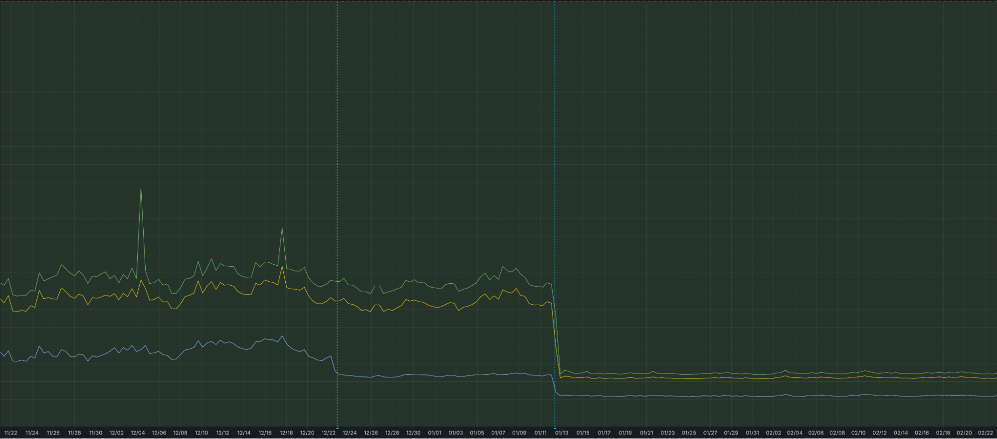
That is why we have optimized our ingestion for better speed and resilience. By increasing concurrency in one part of our ingestion path, we have eliminated bottlenecks that could cause “noisy neighbor” issues, ensuring that one client’s data surge doesn’t slow down another’s visibility. This architectural work has reduced our P99 ingestion latency by approximately 55%, and our P50 by 25%, cutting the time it takes for an event at the edge to become available for your SQL queries.
Grafana chart displaying the drop in ingest latency after architectural upgrades
Follow along for more updates
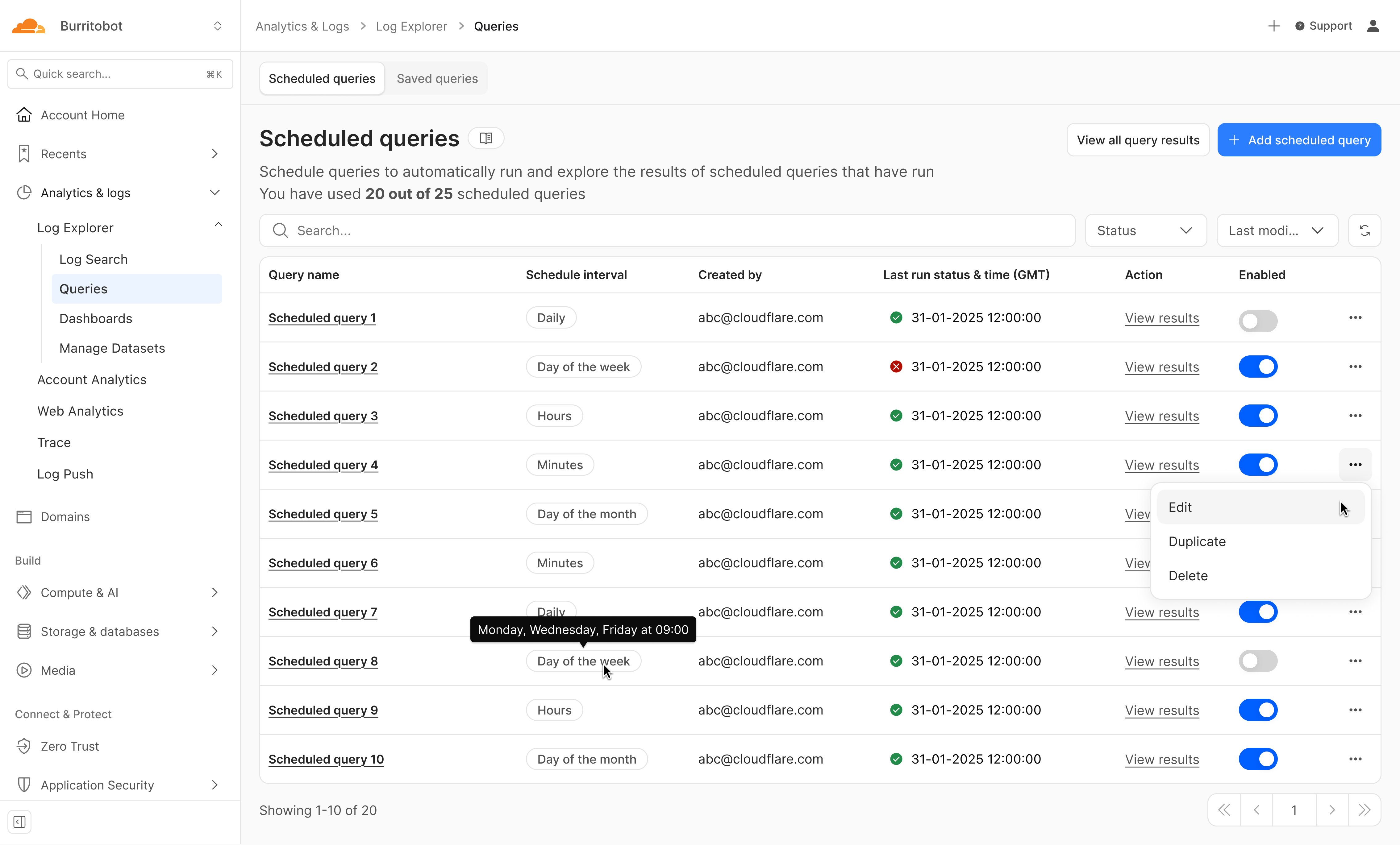
We’re just getting started. We’re actively working on even more powerful features to further enhance your experience with Log Explorer, including the ability to run these detection queries on a custom defined schedule.
Design mockup of upcoming Log Explorer Scheduled Queries feature
To get access to Log Explorer, you can purchase self-serve directly from the dash or for contract customers, reach out for a consultation or contact your account manager. Additionally, you can read more in our Developer Documentation.
Today, we are launching Local Uploads for R2 in open beta. With Local Uploads enabled, object data is automatically written to a storage location close to the client first, then asynchronously copied to where the bucket lives. The data is immediately accessible and stays strongly consistent. Uploads get faster, and data feels global.
For many applications, performance needs to be global. Users uploading media content from different regions, for example, or devices sending logs and telemetry from all around the world. But your data has to live somewhere, and that means uploads from far away have to travel the full distance to reach your bucket.
R2 is object storage built on Cloudflare’s global network. Out of the box, it automatically caches object data globally for fast reads anywhere — all while retaining strong consistency and zero egress fees. This happens behind the scenes whether you’re using the S3 API, Workers Bindings, or plain HTTP. And now with Local Uploads, both reads and writes can be fast from anywhere in the world.
Try it yourself in this demo to see the benefits of Local Uploads.
Ready to try it? Enable Local Uploads in the Cloudflare Dashboard under your bucket’s settings, or with a single Wrangler command on an existing bucket.
75% lower total request duration for global uploads
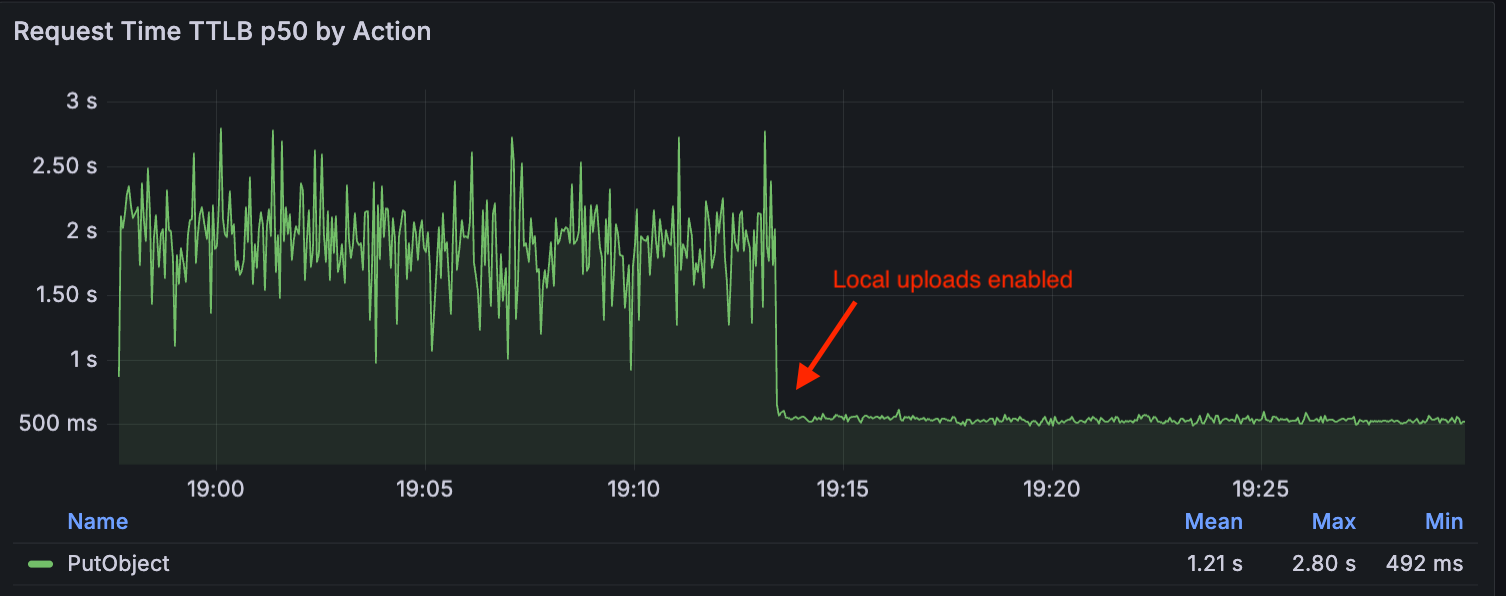
Local Uploads makes upload requests (i.e. PutObject, UploadPart) faster. In both our private beta tests with customers and our synthetic benchmarks, we saw up to 75% reduction in Time to Last Byte (TTLB) when upload requests are made in a different region than the bucket. In these results, TTLB is measured from when R2 receives the upload request to when R2 returns a 200 response.
In our synthetic tests, we measured the impact of Local Uploads by using a synthetic workload to simulate a cross-region upload workflow. We deployed a test client in Western North America and configured an R2 bucket with a location hint for Asia-Pacific. The client performed around 20 PutObject requests per second over 30 minutes to upload objects of 5 MB size.
The following graph compares the p50 (or median) TTLB metrics for these requests, showing the difference in upload request duration — first without Local Uploads (TTLB around 2s), and then with Local Uploads enabled (TTLB around 500ms):
How it works: The distance problem
To understand how Local Uploads can improve upload requests, let’s first take a look at how R2 works. R2’s architecture is composed of multiple components including:
R2 Gateway Worker: The entry point for all API requests that handles authentication and routing logic. It is deployed across Cloudflare’s global network via Cloudflare Workers.
Durable Object Metadata Service: A distributed layer built on Durable Objects used to store and manage object metadata (e.g. object key, checksum).
Distributed Storage Infrastructure: The underlying infrastructure that persistently stores encrypted object data.
Without Local Uploads, here’s what happens when you upload objects to your bucket: The request is first received by the R2 Gateway, close to the user, where it is authenticated. Then, as the client streams bytes of the object data, the data is encrypted and written into the storage infrastructure in the region where the bucket is placed. When this is completed, the Gateway reaches out to the Metadata Service to publish the object metadata, and it returns a success response back to the client after it is committed.
If the client and the bucket are in separate regions, more variability can be introduced in the process of uploading bytes of the object data, due to the longer distance that the request must travel. This could result in slower or less reliable uploads.
A client uploading from Eastern North America to a bucket in Eastern Europe without Local Uploads enabled.
Now, when you make an upload request to a bucket with Local Uploads enabled, there are two cases that are handled:
The client and the bucket region are in the same region
The client and the bucket region are in different regions
In the first case, R2 follows the regular flow, where object data is written to the storage infrastructure for your bucket. In the second case, R2 writes to the storage infrastructure located in the client region while still publishing to the object metadata to the region of the bucket.
Importantly, the object is immediately accessible after the initial write completes. It remains accessible throughout the entire replication process — there’s nowaiting period for background replication to finish before the object can be read.
A client uploading from Eastern North America to a bucket in Eastern Europe with Local Uploads enabled.
Note that this is for non-jurisdiction restricted buckets, and Local Uploads are not available for buckets with jurisdiction restriction (e.g. EU, FedRAMP) enabled.
When to use Local Uploads
Local uploads are built for workloads that receive a lot of upload requests originating from different geographic regions than where your bucket is located. This feature is ideal when:
Your users are globally distributed
Upload performance and reliability is critical to your application
You want to optimize write performance without changing your bucket’s primary location
To understand the geographic distribution of where your read and write requests are initiated, you can visit the Cloudflare Dashboard, and go to your R2 bucket’s Metrics page and view the Request Distribution by Region graph.
How we built Local Uploads
With Local Uploads, object data is written close to the client and then copied to the bucket’s region in the background. We call this copy job a replication task.
Given these replication tasks, we needed an asynchronous processing component for them, which tends to be a great use case for Cloudflare Queues. Queues allow us to control the rate at which we process replication tasks, and it provides built-in failure handling capabilities like retries and dead letter queues. In this case, R2 shards replication tasks across multiple queues per storage region.
Publishing metadata and scheduling replication
When publishing the metadata of an object with Local Uploads enabled, we perform three operations atomically:
Store the object metadata
Create a pending replica key that tracks which replications still need to happen
Create a replication task marker keyed by timestamp, which controls when the task should be sent to the queue
The pending replica key contains the full replication plan: the number of replication tasks, which source location to read from, which destination location to write to, the replication mode and priority, and whether the source should be deleted after successful replication.
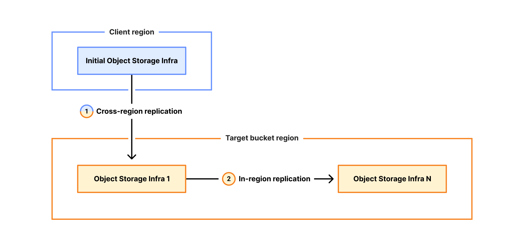
This gives us flexibility in how we move an object’s data. For example, moving data across long geographical distances is expensive. We could try to move all the replicas as fast as possible by processing them in parallel, but this would incur greater cost and pressure the network infrastructure. Instead, we minimize the number of cross-regional data movements by first creating one replica in the target bucket region, and then use this local copy to create additional replicas within the bucket region.
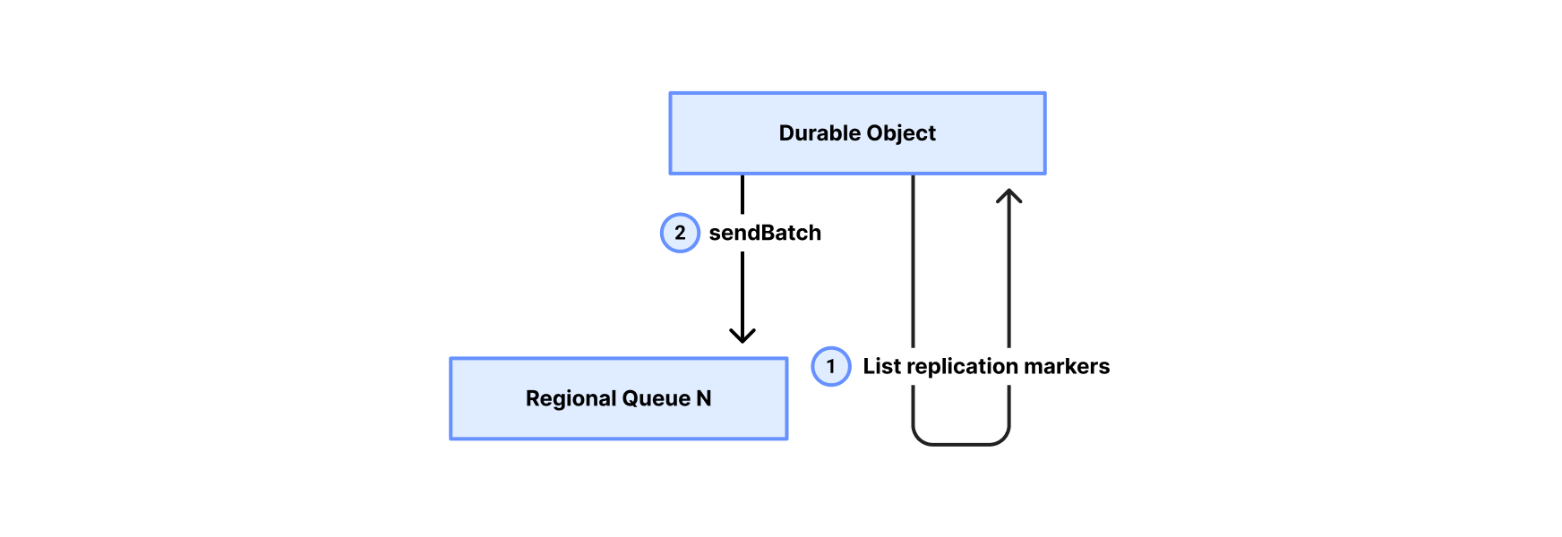
A background process periodically scans the replication task markers and sends them to one of the queues associated with the destination storage region. The markers guarantee at-least-once delivery to the queue — if enqueueing fails or the process crashes, the marker persists and the task will be retried on the next scan. This also allows us to process replications at different times and enqueue only valid tasks. Once a replication task reaches a queue, it is ready to be processed.
Asynchronous replication: Pull model
For the queue consumer, we chose a pull model where a centralized polling service consumes tasks from the regional queues and dispatches them to the Gateway Worker for execution.
Here’s how it works:
Polling service pulls from a regional queue: The consumer service polls the regional queue for replication tasks. It then batches the tasks to create uniform batch sizes based on the amount of data to be moved.
Polling service dispatches to Gateway Worker: The consumer service sends the replication job to the Gateway Worker.
Gateway Worker executes replication: The worker reads object data from the source location, writes it to the destination, and updates metadata in the Durable Object, optionally marking the source location to be garbage collected.
Gateway Worker reports result: On completion, the worker returns the result to the poller, which acknowledges the task to the queue as completed or failed.
By using this pull model approach, we ensure that the replication process remains stable and efficient. The service can dynamically adjust its pace based on real-time system health, guaranteeing that data is safely replicated across regions.
Try it out
Local Uploads is available now in open beta. There is no additional cost to enable Local Uploads. Upload requests made with this feature enabled incur the standard Class A operation costs, same as upload requests made without Local Uploads.
To get started, visit the Cloudflare Dashboard under your bucket’s settings and look for the Local Uploads card to enable, or simply run the following command using Wrangler to enable Local Uploads on a bucket.
Matrix is the gold standard for decentralized, end-to-end encrypted communication. It powers government messaging systems, open-source communities, and privacy-focused organizations worldwide.
For the individual developer, however, the appeal is often closer to home: bridging fragmented chat networks (like Discord and Slack) into a single inbox, or simply ensuring your conversation history lives on infrastructure you control. Functionally, Matrix operates as a decentralized, eventually consistent state machine. Instead of a central server pushing updates, homeservers exchange signed JSON events over HTTP, using a conflict resolution algorithm to merge these streams into a unified view of the room’s history.
But there is a “tax” to running it Traditionally, operating a Matrix homeserver has meant accepting a heavy operational burden. You aren’t just installing software; you are becoming a system administrator. You have to provision virtual private servers (VPS), tune PostgreSQL for heavy write loads, manage Redis for caching, configure reverse proxies, and handle rotation for TLS certificates. It’s a stateful, heavy beast that demands to be fed time and money, whether you are sending one message a day or one million.
We wanted to see if we could eliminate that tax entirely.
Spoiler: We could. In this post, we’ll explain how we ported a complete Matrix homeserver to Cloudflare Workers. The result is a serverless architecture where operations disappear, costs scale to zero when idle, and every connection is protected by post-quantum cryptography by default. You can view the source code and deploy your own instance directly from GitHub.
From Tuwunel to Workers
Our starting point was Tuwunel, a Rust-based Matrix homeserver designed for traditional deployments. PostgreSQL for persistence, Redis for caching, filesystem for media. Porting it to Workers meant questioning every storage assumption we’d taken for granted.
The good news: Rust compiles to WebAssembly, and the core Matrix protocol logic — event authorization, room state resolution, cryptographic verification — translated directly. The workers-rs crate bridges the gap to Cloudflare’s runtime.
The challenge was storage. Traditional homeservers assume strong consistency via a central SQL database. Cloudflare offers a powerful alternative: Durable Objects. This primitive gives us the strong consistency and atomicity required for Matrix state resolution, while still allowing the application to run at the edge.
Here’s how the mapping worked out:
From monolith to serverless
Moving to Cloudflare Workers brings several advantages for a developer: simple deployment, lower costs, low latency, and built-in security.
Easy deployment: A traditional Matrix deployment requires server provisioning, PostgreSQL administration, Redis cluster management, TLS certificate renewal, load balancer configuration, monitoring infrastructure, and on-call rotations.
With Workers, deployment is wrangler deploy. We handle TLS, load balancing, DDoS protection, and global distribution. So there’s no server to patch, no database to vacuum, or certificates to renew.
Usage-based costs: Traditional homeservers cost money whether anyone is using them or not. A small community server handling a few hundred requests per day still requires a typical VPS costing around $20/month running 24/7.
Workers pricing is request-based, so low-traffic homeservers cost just pennies. When usage spikes during active conversations, you pay for what you use. When everyone goes to sleep, costs drop toward zero.
Lower latency globally: A traditional Matrix homeserver in us-east-1 adds 200ms+ latency for users in Asia or Europe. Every sync request, message sent, and typing indicator go round-trip to a single region.
Workers, meanwhile, run in 300+ locations worldwide. When a user in Tokyo sends a message, the Worker executes in Tokyo.
Built-in security: Matrix homeservers can be high-value targets: They handle encrypted communications, store message history, and authenticate users. Traditional deployments require careful hardening: firewall configuration, rate limiting, DDoS mitigation, WAF rules, IP reputation filtering.
We provide all of this by default. The Worker never sees attack traffic, because we filter it first. For a solo developer or small team, achieving this level of hardening on a Linux VPS is a full-time job. On Workers, it is the baseline environment.
An adversary captures your encrypted TLS traffic today and stores it. Years from now, when quantum computers can break classical key exchange algorithms, they decrypt everything retroactively. For a messaging platform handling sensitive communications, this isn’t theoretical. Government agencies and well-funded adversaries are already stockpiling encrypted traffic.
Fortunately, we didn’t have to protect against this by ourselves. Cloudflare deployed post-quantum hybrid key agreement across all TLS 1.3 connections in October 2022. Every connection to our Worker automatically negotiates X25519MLKEM768 — a hybrid combining classical X25519 with ML-KEM, the post-quantum algorithm standardized by NIST.
Classical cryptography relies on mathematical problems that are hard for traditional computers but trivial for quantum computers running Shor’s algorithm. ML-KEM is based on lattice problems that remain hard even for quantum computers. The hybrid approach means both algorithms must fail for the connection to be compromised.
Following a message through the system
Understanding where encryption happens matters for security architecture. When someone sends a message through our homeserver, here’s the actual path:
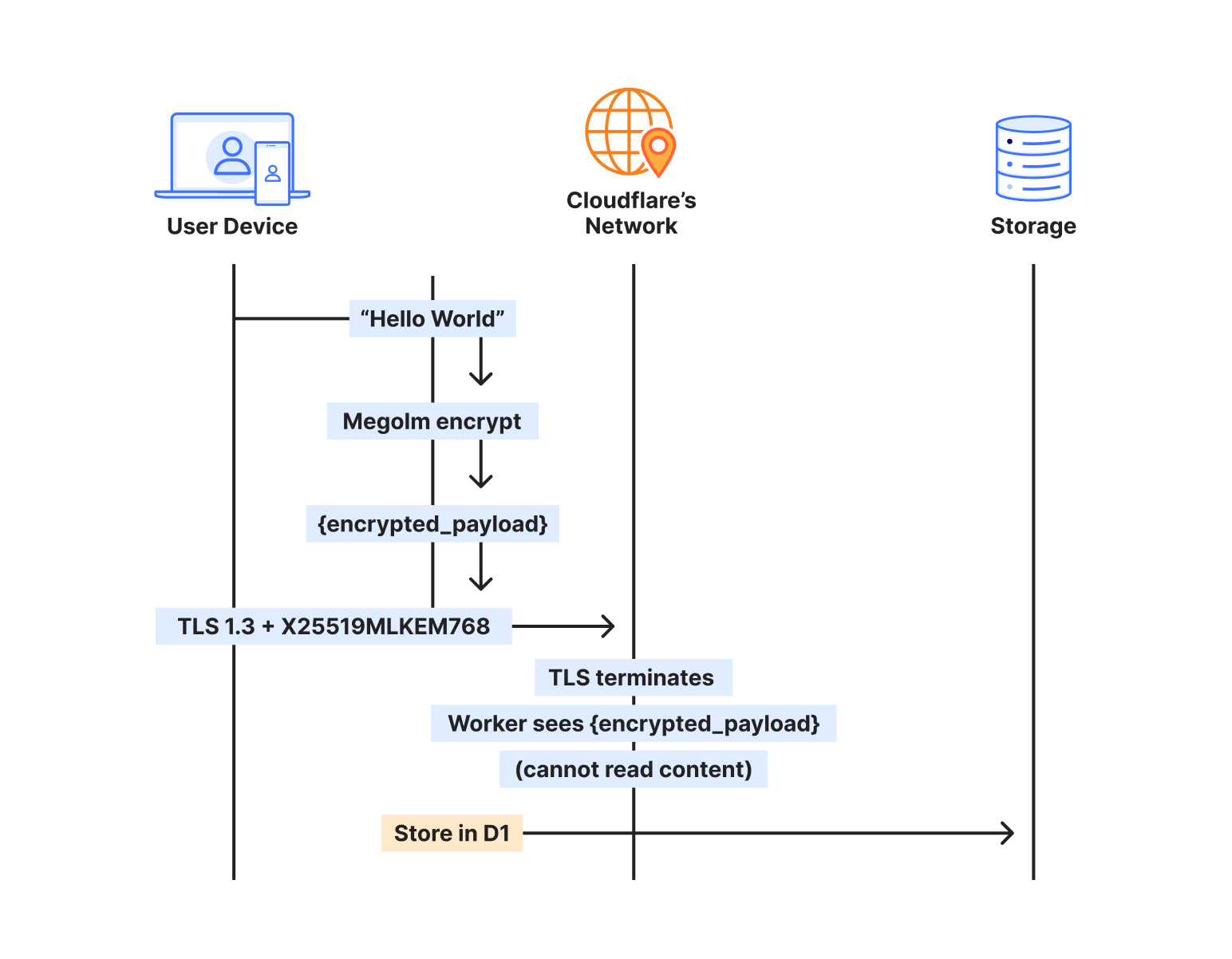
The sender’s client takes the plaintext message and encrypts it with Megolm — Matrix’s end-to-end encryption. This encrypted payload then gets wrapped in TLS for transport. On Cloudflare, that TLS connection uses X25519MLKEM768, making it quantum-resistant.
The Worker terminates TLS, but what it receives is still encrypted — the Megolm ciphertext. We store that ciphertext in D1, index it by room and timestamp, and deliver it to recipients. But we never see the plaintext. The message “Hello, world” exists only on the sender’s device and the recipient’s device.
When the recipient syncs, the process reverses. They receive the encrypted payload over another quantum-resistant TLS connection, then decrypt locally with their Megolm session keys.
Two layers, independent protection
This creates defense in depth through two encryption layers that operate independently:
The transport layer (TLS) protects data in transit. It’s encrypted at the client and decrypted at the Cloudflare edge. With X25519MLKEM768, this layer is now post-quantum.
The application layer (Megolm E2EE) protects message content. It’s encrypted on the sender’s device and decrypted only on recipient devices. This uses classical Curve25519 cryptography.
Here’s why this architecture matters: Even if Matrix E2EE is eventually broken by quantum computers, the message content was never transmitted in a quantum-vulnerable form. The TLS layer that carried the E2EE ciphertext was itself post-quantum secured.
The post-quantum TLS acts as a quantum-resistant envelope around everything, including the classical E2EE layer. This buys time for the Matrix protocol to migrate to post-quantum E2EE algorithms without leaving current communications vulnerable to harvest-now-decrypt-later attacks.
Who sees what
Any Matrix homeserver operator — whether running Synapse on a VPS or this implementation on Workers — can see metadata: which rooms exist, who’s in them, when messages were sent. This is inherent to operating the server. You’re the operator; you control the infrastructure.
What no one in the infrastructure chain can see: message content. The E2EE payload is encrypted on sender devices before it ever hits the network. Cloudflare terminates TLS and passes requests to your Worker, but both see only Megolm ciphertext. Media in encrypted rooms is encrypted client-side before upload. Private keys never leave user devices.
The server processes ciphertext, not conversations. That’s true whether you’re self-hosting on bare metal or running on Workers.
What traditional deployments would need
Achieving post-quantum TLS on a traditional Matrix deployment would require upgrading OpenSSL or BoringSSL to a version supporting ML-KEM, configuring cipher suite preferences correctly, testing client compatibility across all Matrix apps, monitoring for TLS negotiation failures, staying current as PQC standards evolve, and handling clients that don’t support PQC gracefully.
With Workers, it’s automatic. Chrome, Firefox, and Edge all support X25519MLKEM768. Mobile apps using platform TLS stacks inherit this support. The security posture improves as Cloudflare’s PQC deployment expands — no action required on our part.
The storage architecture that made it work
The key insight from porting Tuwunel was that different data needs different consistency guarantees. We use each Cloudflare primitive for what it does best.
D1 for the data model
D1 stores everything that needs to survive restarts and support queries: users, rooms, events, device keys. Over 25 tables covering the full Matrix data model.
CREATE TABLE events (
	event_id TEXT PRIMARY KEY,
	room_id TEXT NOT NULL,
	sender TEXT NOT NULL,
	event_type TEXT NOT NULL,
	state_key TEXT,
	content TEXT NOT NULL,
	origin_server_ts INTEGER NOT NULL,
	depth INTEGER NOT NULL
);
D1’s SQLite foundation meant we could port Tuwunel’s queries with minimal changes. Joins, indexes, and aggregations work as expected.
We learned one hard lesson: D1’s eventual consistency breaks foreign key constraints. A write to rooms might not be visible when a subsequent write to events checks the foreign key — different replicas, different views of the world. We removed all foreign keys and enforce referential integrity in application code.
KV for ephemeral state
OAuth authorization codes live for 10 minutes. Refresh tokens last for a session. None of this needs SQL — it needs fast key-value access with automatic expiration.
// Store OAuth code with 10-minute TTL
kv.put(&format!("oauth_code:{}", code), &token_data)?
	.expiration_ttl(600)
	.execute()
	.await?;
KV’s global distribution means OAuth flows work fast regardless of where users are located.
R2 for media
Matrix media maps directly to R2. Upload an image, get back a content-addressed URL. Egress is free, which matters for a protocol where clients frequently download the same avatars and images.
Durable Objects for atomicity
Some operations can’t tolerate eventual consistency. When a client claims a one-time encryption key, that key must be atomically removed. If two clients claim the same key, encrypted session establishment fails.
Durable Objects provide single-threaded, strongly consistent storage:
#[durable_object]
pub struct UserKeysObject {
	state: State,
	env: Env,
}

impl UserKeysObject {
	async fn claim_otk(&self, algorithm: &str) -> Result<Option<Key>> {
    	// Atomic within single DO - no race conditions possible
    	let mut keys: Vec<Key> = self.state.storage()
        	.get("one_time_keys")
        	.await
        	.ok()
        	.flatten()
        	.unwrap_or_default();

    	if let Some(idx) = keys.iter().position(|k| k.algorithm == algorithm) {
        	let key = keys.remove(idx);
        	self.state.storage().put("one_time_keys", &keys).await?;
        	return Ok(Some(key));
    	}
    	Ok(None)
	}
}
We use UserKeysObject for E2EE key management, RoomObject for real-time room events like typing indicators and read receipts, and UserSyncObject for to-device message queues. The rest flows through D1.
Complete E2EE, complete OAuth
End-to-end encryption is non-negotiable for secure communications. Our implementation supports the full Matrix E2EE stack: device keys, cross-signing keys, one-time keys, fallback keys, key backup, and dehydrated devices.
Modern Matrix clients use OAuth 2.0/OIDC instead of legacy password flows. We implemented a complete OAuth provider: dynamic client registration, PKCE authorization, RS256-signed JWT tokens, token refresh with rotation, and standard OIDC discovery endpoints.
Point Element or any Matrix client at the domain, and it discovers everything automatically.
Sliding Sync for mobile
Traditional Matrix sync transfers megabytes of data on initial connection — every room, every state event, recent timeline for each. This destroys mobile battery and data plans.
Sliding Sync lets clients request exactly what they need. Instead of downloading everything, clients get the 20 most recent rooms with minimal state. As users scroll, they request more ranges. The server tracks position and sends only deltas.
Combined with edge execution, mobile clients can connect and render their room list in under 500ms — even on slow networks.
The comparison
For a homeserver serving a small team:
Traditional (VPS)
Workers
Monthly cost (idle)
$20-50
<$1
Monthly cost (active)
$20-50
$3-10
Global latency
100-300ms
20-50ms
Time to deploy
Hours
Seconds
Maintenance
Weekly
None
DDoS protection
Additional cost
Included
Post-quantum TLS
Complex setup
Automatic
*Based on public rates and metrics published by DigitalOcean, AWS Lightsail, and Linode as of January 15, 2026.
The economics improve further at scale. Traditional deployments require capacity planning and over-provisioning. Workers scale automatically.
The future of decentralized protocols
When we started this project, the goal was simply to see if the pieces would fit. Could a protocol as complex and stateful as Matrix — designed for heavy iron and persistent file systems — actually run on an ephemeral, serverless edge?
The answer is yes, but the implication is bigger than just Matrix.
By mapping traditional stateful components to Cloudflare’s primitives — Postgres to D1, Redis to KV, mutexes to Durable Objects — we proved that complex applications don’t need complex infrastructure. We stripped away the operating system, the database management, and the network configuration, leaving only the application logic and the data itself.
This architecture shifts the paradigm for self-hosting. It turns “running a server” from a chore into a utility. You get the sovereignty of owning your data without the burden of owning the infrastructure.
Matrix on Workers runs in production today, handling real encrypted communications for our team. It is fast, it is cheap, and it is arguably one of the most secure ways to deploy a homeserver today.
Ready to build secure, real-time applications on Workers? Get started withCloudflare Workers and exploreDurable Objects for your own stateful edge applications. Join ourDiscord community to connect with other developers building at the edge.
When you’re dealing with large amounts of data, it’s helpful to get a quick overview — which is exactly what aggregations provide in SQL. Aggregations, known as “GROUP BY queries”, provide a bird’s eye view, so you can quickly gain insights from vast volumes of data.
That’s why we are excited to announce support for aggregations in R2 SQL, Cloudflare’s serverless, distributed, analytics query engine, which is capable of running SQL queries over data stored in R2 Data Catalog. Aggregations will allow users of R2 SQL to spot important trends and changes in the data, generate reports and find anomalies in logs.
This release builds on the already supported filter queries, which are foundational for analytical workloads, and allow users to find needles in haystacks of Apache Parquet files.
In this post, we’ll unpack the utility and quirks of aggregations, and then dive into how we extended R2 SQL to support running such queries over vast amounts of data stored in R2 Data Catalog.
The importance of aggregations in analytics
Aggregations, or “GROUP BY queries”, generate a short summary of the underlying data.
A common use case for aggregations is generating reports. Consider a table called “sales”, which contains historical data of all sales across various countries and departments of some organisation. One could easily generate a report on the volume of sales by department using this aggregation query:
SELECT department, sum(value)
FROM sales
GROUP BY department
The “GROUP BY” statement allows us to split table rows into buckets. Each bucket has a label corresponding to a particular department. Once the buckets are full, we can then calculate “sum(value)” for all rows in each bucket, giving us the total volume of sales performed by the corresponding department.
For some reports, we might only be interested in departments that had the largest volume. That’s where an “ORDER BY” statement comes in handy:
SELECT department, sum(value)
FROM sales
GROUP BY department
ORDER BY sum(value) DESC
LIMIT 10
Here we instruct the query engine to sort all department buckets by their total sales volume in the descending order and only return the top 10 largest.
Finally, we might be interested in filtering out anomalies. For example, we might want to only include departments that had more than five sales total in our report. We can easily do that with a “HAVING” statement:
SELECT department, sum(value), count(*)
FROM sales
GROUP BY department
HAVING count(*) > 5
ORDER BY sum(value) DESC
LIMIT 10
Here we added a new aggregate function to our query — “count(*)” — which calculates how many rows ended up in each bucket. This directly corresponds to the number of sales in each department, so we have also added a predicate in the “HAVING” statement to make sure that we only leave buckets with more than five rows in them.
Two approaches to aggregation: compute sooner or later
Aggregation queries have a curious property: they can reference columns that are not stored anywhere. Consider “sum(value)”: this column is computed by the query engine on the fly, unlike the “department” column, which is fetched from Parquet files stored on R2. This subtle difference means that any query that references aggregates like “sum”, “count” and others needs to be split into two phases.
The first phase is computing new columns. If we are to sort the data by “count(*)” column using “ORDER BY” statement or filter rows based on it using “HAVING” statement, we need to know the values of this column. Once the values of columns like “count(*)” are known, we can proceed with the rest of the query execution.
Note that if the query does not reference aggregate functions in “HAVING” or “ORDER BY”, but still uses them in “SELECT”, we can make use of a trick. Since we do not need the values of aggregate functions until the very end, we can compute them partially and merge results just before we are about to return them to the user.
The key difference between the two approaches is when we compute aggregate functions: in advance, to perform some additional computations on them later; or on the fly, to iteratively build results the user needs.
First, we will dive into building results on the fly — a technique we call “scatter-gather aggregations.” We will then build on top of that to introduce “shuffling aggregations” capable of running extra computations like “HAVING” and “ORDER BY” on top of aggregate functions.
Scatter-gather aggregations
Aggregate queries without “HAVING” and “ORDER BY” can be executed in a fashion similar to filter queries. For filter queries, R2 SQL picks one node to be the coordinator in query execution. This node analyzes the query and consults R2 Data Catalog to figure out which Parquet row groups may contain data relevant to the query. Each Parquet row group represents a relatively small piece of work that a single compute node can handle. Coordinator node distributes the work across many worker nodes and collects results to return them to the user.
In order to execute aggregate queries, we follow all the same steps and distribute small pieces of work between worker nodes. However, this time instead of just filtering rows based on the predicate in the “WHERE” statement, worker nodes also compute pre-aggregates.
Pre-aggregates represent an intermediary state of an aggregation. This is an incomplete piece of data representing a partially computed aggregate function on a subset of data. Multiple pre-aggregates can be merged together to compute the final value of an aggregate function. Splitting aggregate functions into pre-aggregates allows us to horizontally scale computation of aggregation, making use of vast compute resources available in Cloudflare’s network.
For example, pre-aggregate for “count(*)” is simply a number representing the count of rows in a subset of data. Computing the final “count(*)” is as easy as adding these numbers together. Pre-aggregate for “avg(value)” consists of two numbers: “sum(value)” and “count(*)”. The value of “avg(value)” can then be computed by adding together all “sum(value)” values, adding together all “count(*)” values and finally dividing one number by the other.
Once worker nodes have finished computing the pre-aggregates, they stream results to the coordinator node. The coordinator node collects all results, computes final values of aggregate functions from pre-aggregates, and returns the result to the user.
Shuffling, beyond the limits of scatter-gather
Scatter-gather is highly efficient when the coordinator can compute the final result by merging small, partial states from workers. If you run a query like SELECT sum(sales) FROM orders, the coordinator receives a single number from each worker and adds them up. The memory footprint on the coordinator is negligible regardless of how much data resides in R2.
However, this approach becomes inefficient when the query requires sorting or filtering based on the result of an aggregation. Consider this query, which finds the top two departments by sales volume:
SELECT department, sum(sales)
FROM sales
GROUP BY department
ORDER BY sum(sales) DESC
LIMIT 2
Correctly determining the global Top 2 requires knowing the total sales for every department across the entire dataset. Because the data is spread effectively at random across the underlying Parquet files, sales for a specific department are likely split across many different workers. A department might have low sales on every individual worker, excluding it from any local Top 2 list, yet have the highest sales volume globally when summed together.
The diagram below illustrates how a scatter-gather approach would not work for this query. “Dept A” is the global sales leader, but because its sales are evenly spread across workers, it doesn’t make to some local Top 2 lists, and ends up being discarded by the coordinator.
Consequently, when the query orders results by their global aggregation, the coordinator cannot rely on pre-filtered results from workers. It must request the total count for every department from every worker to calculate the global totals before it can sort them. If you are grouping by a high-cardinality column like IP addresses or User IDs, this forces the coordinator to ingest and merge millions of rows, creating a resource bottleneck on a single node.
To solve this, we need shuffling, a way to colocate data for specific groups before the final aggregation occurs.
Shuffling of aggregation data
To address the challenges of random data distribution, we introduce a shuffling stage. Instead of sending results to the coordinator, workers exchange data directly with each other to colocate rows based on their grouping key.
This routing relies on deterministic hash partitioning. When a worker processes a row, it hashes the GROUP BY column to identify the destination worker. Because this hash is deterministic, every worker in the cluster independently agrees on where to send specific data. If “Engineering” hashes to Worker 5, every worker knows to route “Engineering” rows to Worker 5. No central registry is required.
The diagram below illustrates this flow. Notice how “Dept A” starts on Workers 1, 2 and 3. Because the hash function maps “Dept A” to Worker 1, all workers route those rows to that same destination.
Shuffling aggregates produces the correct results. However, this all-to-all exchange creates a timing dependency. If Worker 1 begins calculating the final total for “Dept A” before Worker 3 has finished sending its share of the data, the result will be incomplete.
To address this, we enforce a strict synchronization barrier. The coordinator tracks the progress of the entire cluster while workers buffer their outgoing data and flush it via gRPC streams to their peers. Only when every worker confirms that it has finished processing its input files and flushing its shuffle buffers does the coordinator issue the command to proceed. This barrier guarantees that when the next stage begins, the dataset on each worker is complete and accurate.
Local finalization
Once the synchronization barrier is lifted, every worker holds the complete dataset for its assigned groups. Worker 1 now has 100% of the sales records for “Dept A” and can calculate the final total with certainty.
This allows us to push computational logic like filtering and sorting down to the worker rather than burdening the coordinator. For example, if the query includes HAVING count(*) > 5, the worker can filter out groups that do not meet this criteria immediately after aggregation.
At the end of this stage, each worker produces a sorted, finalized stream of results for the groups it owns.
The streaming merge
The final piece of the puzzle is the coordinator. In the scatter-gather model, the coordinator was responsible for the expensive task of aggregating and sorting the entire dataset. In the shuffling model, its role changes.
Because the workers have already computed the final aggregates and sorted them locally, the coordinator only needs to perform a k-way merge. It opens a stream to every worker and reads the results row by row. It compares the current row from each worker, picks the “winner” based on the sort order, and adds it to the query results that will be sent to the user.
This approach is particularly powerful for LIMIT queries. If a user asks for the top 10 departments, the coordinator merges the streams until it has found the top 10 items and then immediately stops processing. It does not need to load or merge the millions of remaining rows, allowing for greater scale of operation without over-consumption of compute resources.
A powerful engine for processing massive datasets
With the addition of aggregations, R2 SQL transforms from a tool great for filtering data into a powerful engine capable of data processing on massive datasets. This is made possible by implementing distributed execution strategies like scatter-gather and shuffling, where we are able to push the compute to where the data lives, using the scale of Cloudflare’s global compute and network.
Whether you are generating reports, monitoring high-volume logs for anomalies, or simply trying to spot trends in your data, you can now easily do it all within Cloudflare’s Developer Platform without the overhead of managing complex OLAP infrastructure or moving data out of R2.
Try it now
Support for aggregations in R2 SQL is available today. We are excited to see how you use these new functions with data in R2 Data Catalog.
Get Started: Check out our documentation for examples and syntax guides on running aggregation queries.
Join the Conversation: If you have questions, feedback, or want to share what you’re building, join us in the Cloudflare Developer Discord.
Remote bindings are bindings that connect to a deployed resource on your Cloudflare account instead of a locally simulated resource – and recently, we announced that remote bindings are now generally available.
With this launch, you can now connect to deployed resources like R2 buckets and D1 databases while running Worker code on your local machine. This means you can test your local code changes against real data and services, without the overhead of deploying for each iteration.
In this blog post, we’ll dig into the technical details of how we built it, creating a seamless local development experience.
Developing on the Workers platform
A key part of the Cloudflare Workers platform has been the ability to develop your code locally without having to deploy it every time you wanted to test something – though the way we’ve supported this has changed greatly over the years.
We started with wrangler dev running in remote mode. This works by deploying and connecting to a preview version of your Worker that runs on Cloudflare’s network every time you make a change to your code, allowing you to test things out as you develop. However, remote mode isn’t perfect — it’s complex and hard to maintain. And the developer experience leaves a lot to be desired: slow iteration speed, unstable debugging connections, and lack of support for multi-worker scenarios.
Still, the original remote mode remained accessible via a flag: wrangler dev --remote. When using remote mode, all the DX benefits of a fully local experience and the improvements we’ve made over the last few years are bypassed. So why do people still use it? It enables one key unique feature: binding to remote resources while locally developing. When you use local mode to develop a Worker locally, all of your bindings are simulated locally using local (initially empty) data. This is fantastic for iterating on your app’s logic with test data – but sometimes that’s not enough, whether you want to share resources across your team, reproduce bugs tied to real data, or just be confident that your app will work in production with real resources.
Given this, we saw an opportunity: If we could bring the best parts of remote mode (i.e. access to remote resources) to wrangler dev, there’d be one single flow for developing Workers that would enable many use cases, while not locking people out of the advancements we’ve made to local development. And that’s what we did!
As of Wrangler v4.37.0 you can pick on a per-binding basis whether a binding should use remote or local resources, simply by specifying the remote option. It’s important to re-emphasise this—you only need to add remote: true! There’s no complex management of API keys and credentials involved, it all just works using Wrangler’s existing Oauth connection to the Cloudflare API.
The eagle-eyed among you might have realised that some bindings already worked like this, accessing remote resources from local dev. Most prominently, the AI binding was a trailblazer for what a general remote bindings solution could look like. From its introduction, the AI binding always connected to a remote resource, since a true local experience that supports all the different models you can use with Workers AI would be impractical and require a huge upfront download of AI models.
As we realised different products within Workers needed something similar to remote bindings (Images and Hyperdrive, for instance), we ended up with a bit of a patchwork of different solutions. We’ve now unified under a single remote bindings solution that works for all binding types.
How we built it
We wanted to make it really easy for developers to access remote resources without having to change their production Workers code, and so we landed on a solution that required us to fetch data from the remote resource at the point of use in your Worker.
const value = await env.KV.get("some-key")
The above code snippet shows accessing the “some-key” value in the env.KV KV namespace, which is not available locally and needs to be fetched over the network.
So if that was our requirement, how would we get there? For instance, how would we get from a user calling env.KV.put(“key”, “value”) in their Worker to actually storing that in a remote KV store? The obvious solution was perhaps to use the Cloudflare API. We could have just replaced the entire env locally with stub objects that made API calls, transforming env.KV.put() into PUT http:///accounts/{account_id}/storage/kv/namespaces/{namespace_id}/values/{key_name}.
This would’ve worked great for KV, R2, D1, and other bindings with mature HTTP APIs, but it would have been a pretty complex solution to implement and maintain. We would have had to replicate the entire bindings API surface and transform every possible operation on a binding to an equivalent API call. Additionally, some binding operations don’t have an equivalent API call, and wouldn’t be supportable using this strategy.
Instead, we realised that we already had a ready-made API waiting for us — the one we use in production!
How bindings work under the hood in production
Most bindings on the Workers platform boil down to essentially a service binding. A service binding is a link between two Workers that allows them to communicate over HTTP or JSRPC (we’ll come back to JSRPC later).
For example, the KV binding is implemented as a service binding between your authored Worker and a platform Worker, speaking HTTP. The JS API for the KV binding is implemented in the Workers runtime, and translates calls like env.KV.get() to HTTP calls to the Worker that implements the KV service.
Diagram showing a simplified model of how a KV binding works in production
You may notice that there’s a natural async network boundary here — between the runtime translating the env.KV.get() call and the Worker that implements the KV service. We realised that we could use that natural network boundary to implement remote bindings. Instead of the production runtime translating env.KV.get() to an HTTP call, we could have the local runtime (workerd) translate env.KV.get() to an HTTP call, and then send it directly to the KV service, bypassing the production runtime. And so that’s what we did!
Diagram showing a locally run worker with a single KV binding, with a single remote proxy client that communicates to the remote proxy server, which in turn communicates with the remote KV
The above diagram shows a local Worker running with a remote KV binding. Instead of being handled by the local KV simulation, it’s now being handled by a remote proxy client. This Worker then communicates with a remote proxy server connected to the real remote KV resource, ultimately allowing the local Worker to communicate with the remote KV data seamlessly.
Each binding can independently either be handled by a remote proxy client (all connected to the same remote proxy server) or by a local simulation, allowing for very dynamic workflows where some bindings are locally simulated while others connect to the real remote resource, as illustrated in the example below:
The above diagram and config shows a Worker (running on your computer) bound to 3 different resources—two local (KV & R2), and one remote (KV_2)
How JSRPC fits in
The above section deals with bindings that are backed by HTTP connections (like KV and R2), but modern bindings use JSRPC. That means we needed a way for the locally running workerd to speak JSRPC to a production runtime instance.
In a stroke of good luck, a parallel project was going on to make this possible, as detailed in the Cap’n Web blog. We integrated that by making the connection between the local workerd instance and the remote runtime instance communicate over websockets using Cap’n Web, enabling bindings backed by JSRPC to work. This includes newer bindings like Images, as well as JSRPC service bindings to your own Workers.
Remote bindings with Vite, Vitest and the JavaScript ecosystem
We didn’t want to limit this exciting new feature to only wrangler dev. We wanted to support it in our Cloudflare Vite Plugin and vitest-pool-workers packages, as well as allowing any other potential tools and use cases from the JavaScript ecosystem to also benefit from it.
In order to achieve this, the wrangler package now exports utilities such as startRemoteProxySession that allow tools not leveraging wrangler dev to also support remote bindings. You can find more details in the official remote bindings documentation.
How do I try this out?
Just use wrangler dev! As of Wrangler v4.37.0 (@cloudflare/vite-plugin v1.13.0, @cloudflare/vitest-pool-workers v0.9.0), remote bindings are available in all projects, and can be turned on a per-binding basis by adding remote: true to the binding definition in your Wrangler config file.
How do you run SQL queries over petabytes of data… without a server?
We have an answer for that: R2 SQL, a serverless query engine that can sift through enormous datasets and return results in seconds.
This post details the architecture and techniques that make this possible. We’ll walk through our Query Planner, which uses R2 Data Catalog to prune terabytes of data before reading a single byte, and explain how we distribute the work across Cloudflare’s global network, Workers and R2 for massively parallel execution.
From catalog to query
During Developer Week 2025, we launched R2 Data Catalog, a managed Apache Iceberg catalog built directly into your Cloudflare R2 bucket. Iceberg is an open table format that provides critical database features like transactions and schema evolution for petabyte-scale object storage. It gives you a reliable catalog of your data, but it doesn’t provide a way to query it.
Until now, reading your R2 Data Catalog required setting up a separate service like Apache Spark or Trino. Operating these engines at scale is not easy: you need to provision clusters, manage resource usage, and be responsible for their availability, none of which contributes to the primary goal of getting value from your data.
R2 SQL removes that step entirely. It’s a serverless query engine that executes retrieval SQL queries against your Iceberg tables, right where your data lives.
Designing a query engine for petabytes
Object storage is fundamentally different from a traditional database’s storage. A database is structured by design; R2 is an ocean of objects, where a single logical table can be composed of potentially millions of individual files, large and small, with more arriving every second.
Apache Iceberg provides a powerful layer of logical organization on top of this reality. It works by managing the table’s state as an immutable series of snapshots, creating a reliable, structured view of the table by manipulating lightweight metadata files instead of rewriting the data files themselves.
However, this logical structure doesn’t change the underlying physical challenge: an efficient query engine must still find the specific data it needs within that vast collection of files, and this requires overcoming two major technical hurdles:
The I/O problem: A core challenge for query efficiency is minimizing the amount of data read from storage. A brute-force approach of reading every object is simply not viable. The primary goal is to read only the data that is absolutely necessary.
The Compute problem: The amount of data that does need to be read can still be enormous. We need a way to give the right amount of compute power to a query, which might be massive, for just a few seconds, and then scale it down to zero instantly to avoid waste.
Our architecture for R2 SQL is designed to solve these two problems with a two-phase approach: a Query Planner that uses metadata to intelligently prune the search space, and a Query Execution system that distributes the work across Cloudflare’s global network to process the data in parallel.
Query Planner
The most efficient way to process data is to avoid reading it in the first place. This is the core strategy of the R2 SQL Query Planner. Instead of exhaustively scanning every file, the planner makes use of the metadata structure provided by R2 Data Catalog to prune the search space, that is, to avoid reading huge swathes of data irrelevant to a query.
This is a top-down investigation where the planner navigates the hierarchy of Iceberg metadata layers, using stats at each level to build a fast plan, specifying exactly which byte ranges the query engine needs to read.
What do we mean by “stats”?
When we say the planner uses “stats” we are referring to summary metadata that Iceberg stores about the contents of the data files. These statistics create a coarse map of the data, allowing the planner to make decisions about which files to read, and which to ignore, without opening them.
There are two primary levels of statistics the planner uses for pruning:
Partition-level stats: Stored in the Iceberg manifest list, these stats describe the range of partition values for all the data in a given Iceberg manifest file. For a partition on day(event_timestamp), this would be the earliest and latest day present in the files tracked by that manifest.
Column-level stats: Stored in the manifest files, these are more granular stats about each individual data file. Data files in R2 Data Catalog are formatted using the Apache Parquet. For every column of a Parquet file, the manifest stores key information like:
The minimum and maximum values. If a query asks for http_status = 500, and a file’s stats show its http_status column has a min of 200 and a max of 404, that entire file can be skipped.
A count of null values. This allows the planner to skip files when a query specifically looks for non-null values (e.g., WHERE error_code IS NOT NULL) and the file’s metadata reports that all values for error_code are null.
Now, let’s see how the planner uses these stats as it walks through the metadata layers.
Pruning the search space
The pruning process is a top-down investigation that happens in three main steps:
Table metadata and the current snapshot
The planner begins by asking the catalog for the location of the current table metadata. This is a JSON file containing the table’s current schema, partition specs, and a log of all historical snapshots. The planner then fetches the latest snapshot to work with.
2. Manifest list and partition pruning
The current snapshot points to a single Iceberg manifest list. The planner reads this file and uses the partition-level stats for each entry to perform the first, most powerful pruning step, discarding any manifests whose partition value ranges don’t satisfy the query. For a table partitioned by day(event_timestamp), the planner can use the min/max values in the manifest list to immediately discard any manifests that don’t contain data for the days relevant to the query.
3. Manifests and file-level pruning
For the remaining manifests, the planner reads each one to get a list of the actual Parquet data files. These manifest files contain more granular, column-level stats for each individual data file they track. This allows for a second pruning step, discarding entire data files that cannot possibly contain rows matching the query’s filters.
4. File row-group pruning
Finally, for the specific data files that are still candidates, the Query Planner uses statistics stored inside Parquet file’s footers to skip over entire row groups.
The result of this multi-layer pruning is a precise list of Parquet files, and of row groups within those Parquet files. These become the query work units that are dispatched to the Query Execution system for processing.
The Planning pipeline
In R2 SQL, the multi-layer pruning we’ve described so far isn’t a monolithic process. For a table with millions of files, the metadata can be too large to process before starting any real work. Waiting for a complete plan would introduce significant latency.
Instead, R2 SQL treats planning and execution together as a concurrent pipeline. The planner’s job is to produce a stream of work units for the executor to consume as soon as they are available.
The planner’s investigation begins with two fetches to get a map of the table’s structure: one for the table’s snapshot and another for the manifest list.
Starting execution as early as possible
From that point on, the query is processed in a streaming fashion. As the Query Planner reads through the manifest files and subsequently the data files they point to and prunes them, it immediately emits any matching data files/row groups as work units to the execution queue.
This pipeline structure ensures the compute nodes can begin the expensive work of data I/O almost instantly, long before the planner has finished its full investigation.
On top of this pipeline model, the planner adds a crucial optimization: deliberate ordering. The manifest files are not streamed in an arbitrary sequence. Instead, the planner processes them in an order matching by the query’s ORDER BY clause, guided by the metadata stats. This ensures that the data most likely to contain the desired results is processed first.
These two concepts work together to address query latency from both ends of the query pipeline.
The streamed planning pipeline lets us start crunching data as soon as possible, minimizing the delay before the first byte is processed. At the other end of the pipeline, the deliberate ordering of that work lets us finish early by finding a definitive result without scanning the entire dataset.
The next section explains the mechanics behind this “finish early” strategy.
Stopping early: how to finish without reading everything
Thanks to the Query Planner streaming work units in an order matching the ORDER BY clause, the Query Execution system first processes the data that is most likely to be in the final result set.
This prioritization happens at two levels of the metadata hierarchy:
Manifest ordering: The planner first inspects the manifest list. Using the partition stats for each manifest (e.g., the latest timestamp in that group of files), it decides which entire manifest files to stream first.
Parquet file ordering: As it reads each manifest, it then uses the more granular column-level stats to decide the processing order of the individual Parquet files within that manifest.
This ensures a constantly prioritized stream of work units is sent to the execution engine. This prioritized stream is what allows us to stop the query early.
For instance, with a query like … ORDER BY timestamp DESC LIMIT 5, as the execution engine processes work units and sends back results, the planner does two things concurrently:
It maintains a bounded heap of the best 5 results seen so far, constantly comparing new results to the oldest timestamp in the heap.
It keeps a “high-water mark” on the stream itself. Thanks to the metadata, it always knows the absolute latest timestamp of any data file that has not yet been processed.
The planner is constantly comparing the state of the heap to the water mark of the remaining stream. The moment the oldest timestamp in our Top 5 heap is newer than the high-water mark of the remaining stream, the entire query can be stopped.
At that point, we can prove no remaining work unit could possibly contain a result that would make it into the top 5. The pipeline is halted, and a complete, correct result is returned to the user, often after reading only a fraction of the potentially matching data.
Currently, R2 SQL supports ordering on columns that are part of the table’s partition key only. This is a limitation we are working on lifting in the future.
Architecture
Query Execution
Query Planner streams the query work in bite-sized pieces called row groups. A single Parquet file usually contains multiple row groups, but most of the time only a few of them contain relevant data. Splitting query work into row groups allows R2 SQL to only read small parts of potentially multi-GB Parquet files.
The server that receives the user’s request and performs query planning assumes the role of query coordinator. It distributes the work across query workers and aggregates results before returning them to the user.
Cloudflare’s network is vast, and many servers can be in maintenance at the same time. The query coordinator contacts Cloudflare’s internal API to make sure only healthy, fully functioning servers are picked for query execution. Connections between coordinator and query worker go through Cloudflare Argo Smart Routing to ensure fast, reliable connectivity.
Servers that receive query execution requests from the coordinator assume the role of query workers. Query workers serve as a point of horizontal scalability in R2 SQL. With a higher number of query workers, R2 SQL can process queries faster by distributing the work among many servers. That’s especially true for queries covering large amounts of files.
Both the coordinator and query workers run on Cloudflare’s distributed network, ensuring R2 SQL has plenty of compute power and I/O throughput to handle analytical workloads.
Each query worker receives a batch of row groups from the coordinator as well as an SQL query to run on it. Additionally, the coordinator sends serialized metadata about Parquet files containing the row groups. Thanks to that, query workers know exact byte offsets where each row group is located in the Parquet file without the need to read this information from R2.
Apache DataFusion
Internally, each query worker uses Apache DataFusion to run SQL queries against row groups. DataFusion is an open-source analytical query engine written in Rust. It is built around the concept of partitions. A query is split into multiple concurrent independent streams, each working on its own partition of data.
Partitions in DataFusion are similar to partitions in Iceberg, but serve a different purpose. In Iceberg, partitions are a way to physically organize data on object storage. In DataFusion, partitions organize in-memory data for query processing. While logically they are similar – rows grouped together based on some logic – in practice, a partition in Iceberg doesn’t always correspond to a partition in DataFusion.
DataFusion partitions map perfectly to the R2 SQL query worker’s data model because each row group can be considered its own independent partition. Thanks to that, each row group is processed in parallel.
At the same time, since row groups usually contain at least 1000 rows, R2 SQL benefits from vectorized execution. Each DataFusion partition stream can execute the SQL query on multiple rows in one go, amortizing the overhead of query interpretation.
There are two ends of the spectrum when it comes to query execution: processing all rows sequentially in one big batch and processing each individual row in parallel. Sequential processing creates a so-called “tight loop”, which is usually more CPU cache friendly. In addition to that, we can significantly reduce interpretation overhead, as processing a large number of rows at a time in batches means that we go through the query plan less often. Completely parallel processing doesn’t allow us to do these things, but makes use of multiple CPU cores to finish the query faster.
DataFusion’s architecture allows us to achieve a balance on this scale, reaping benefits from both ends. For each data partition, we gain better CPU cache locality and amortized interpretation overhead. At the same time, since many partitions are processed in parallel, we distribute the workload between multiple CPUs, cutting the execution time further.
In addition to the smart query execution model, DataFusion also provides first-class Parquet support.
As a file format, Parquet has multiple optimizations designed specifically for query engines. Parquet is a column-based format, meaning that each column is physically separated from others. This separation allows better compression ratios, but it also allows the query engine to read columns selectively. If the query only ever uses five columns, we can only read them and skip reading the remaining fifty. This massively reduces the amount of data we need to read from R2 and the CPU time spent on decompression.
DataFusion does exactly that. Using R2 ranged reads, it is able to read parts of the Parquet files containing the requested columns, skipping the rest.
DataFusion’s optimizer also allows us to push down any filters to the lowest levels of the query plan. In other words, we can apply filters right as we are reading values from Parquet files. This allows us to skip materialization of results we know for sure won’t be returned to the user, cutting the query execution time further.
Returning query results
Once the query worker finishes computing results, it returns them to the coordinator through the gRPC protocol.
R2 SQL uses Apache Arrow for internal representation of query results. Arrow is an in-memory format that efficiently represents arrays of structured data. It is also used by DataFusion during query execution to represent partitions of data.
In addition to being an in-memory format, Arrow also defines the Arrow IPC serialization format. Arrow IPC isn’t designed for long-term storage of the data, but for inter-process communication, which is exactly what query workers and the coordinator do over the network. The query worker serializes all the results into the Arrow IPC format and embeds them into the gRPC response. The coordinator in turn deserializes results and can return to working on Arrow arrays.
Future plans
While R2 SQL is currently quite good at executing filter queries, we also plan to rapidly add new capabilities over the coming months. This includes, but is not limited to, adding:
Support for complex aggregations in a distributed and scalable fashion;
Tools to help provide visibility in query execution to help developers improve performance;
Support for many of the configuration options Apache Iceberg supports.
In addition to that, we have plans to improve our developer experience by allowing users to query their R2 Data Catalogs using R2 SQL from the Cloudflare Dashboard.
Given Cloudflare’s distributed compute, network capabilities, and ecosystem of developer tools, we have the opportunity to build something truly unique here. We are exploring different kinds of indexes to make R2 SQL queries even faster and provide more functionality such as full text search, geospatial queries, and more.
Try it now!
It’s early days for R2 SQL, but we’re excited for users to get their hands on it. R2 SQL is available in open beta today! Head over to ourgetting started guide to learn how to create an end-to-end data pipeline that processes and delivers events to an R2 Data Catalog table, which can then be queried with R2 SQL.
We’re excited to see what you build! Come share your feedback with us on ourDeveloper Discord.
Many developers, data scientists, and researchers do much of their work in Python notebooks: they’ve been the de facto standard for data science and sharing for well over a decade. Notebooks are popular because they make it easy to code, explore data, prototype ideas, and share results. We use them heavily at Cloudflare, and we’re seeing more and more developers use notebooks to work with data – from analyzing trends in HTTP traffic, querying Workers Analytics Engine through to querying their own Iceberg tables stored in R2.
Traditional notebooks are incredibly powerful — but they were not built with collaboration, reproducibility, or deployment as data apps in mind. As usage grows across teams and workflows, these limitations face the reality of work at scale.
marimo reimagines the notebook experience with these challenges in mind. It’s an open-source reactive Python notebook that’s built to be reproducible, easy to track in Git, executable as a standalone script, and deployable. We have partnered with the marimo team to bring this streamlined, production-friendly experience to Cloudflare developers. Spend less time wrestling with tools and more time exploring your data.
Want to start exploring your Cloudflare data with marimo right now? Head over to notebooks.cloudflare.com. Or, keep reading to learn more about marimo, how we’ve made authentication easy from within notebooks, and how you can use marimo to explore and share notebooks and apps on Cloudflare.
Why marimo?
marimo is an open-source reactive Python notebook designed specifically for working with data, built from the ground up to solve many problems with traditional notebooks.
The core feature that sets marimo apart from traditional notebooks is its reactive execution model, powered by a statically inferred dataflow graph on cells. Run a cell or interact with a UI element, and marimo either runs dependent cells or marks them as stale (your choice). This keeps code and outputs consistent, prevents bugs before they happen, and dramatically increases the speed at which you can experiment with data.
Thanks to reactive execution, notebooks are also deployable as data applications, making them easy to share. While you can run marimo notebooks locally, on cloud servers, GPUs — anywhere you can traditionally run software — you can also run them entirely in the browser with WebAssembly, bringing the cost of sharing down to zero.
Because marimo notebooks are stored as Python, they enjoy all the benefits of software: version with Git, execute as a script or pipeline, test with pytest, inline package requirements with uv, and import symbols from your notebook into other Python modules. Though stored as Python, marimo also supports SQL and data sources like DuckDB, Postgres, and Iceberg-based data catalogs (which marimo’s AI assistant can access, in addition to data in RAM).
To get an idea of what a marimo notebook is like, check out the embedded example notebook below:
Want to create your own notebook to run locally instead? Here’s a quick example that shows you how to authenticate with your Cloudflare account and list the zones you have access to:
mkdir cloudflare-zones-notebook
cd cloudflare-zones-notebook
3. Initialize a new uv project (this creates a .venv and a pyproject.toml):
uv init
4. Add marimo and required dependencies:
uv add marimo
5. Create a file called list-zones.py and paste in the following notebook:
import marimo

__generated_with = "0.14.10"
app = marimo.App(width="full", auto_download=["ipynb", "html"])


@app.cell
def _():
    from moutils.oauth import PKCEFlow
    import requests

    # Start OAuth PKCE flow to authenticate with Cloudflare
    auth = PKCEFlow(provider="cloudflare")

    # Renders login UI in notebook
    auth
    return (auth,)


@app.cell
def _(auth):
    import marimo as mo
    from cloudflare import Cloudflare

    mo.stop(not auth.access_token, mo.md("Please **sign in** using the button above."))
    client = Cloudflare(api_token=auth.access_token)

    zones = client.zones.list()
    [zone.name for zone in zones.result]
    return


if __name__ == "__main__":
    app.run()
6. Open the notebook editor:
uv run marimo edit list-zones.py --sandbox
7. Log in via the OAuth prompt in the notebook. Once authenticated, you’ll see a list of your Cloudflare zones in the final cell.
That’s it! From here, you can expand the notebook to call Workers AI models, query Iceberg tables in R2 Data Catalog, or interact with any Cloudflare API.
How OAuth works in notebooks
Think of OAuth like a secure handshake between your notebook and Cloudflare. Instead of copying and pasting API tokens, you just click “Sign in with Cloudflare” and the notebook handles the rest.
We built this experience using PKCE (Proof Key for Code Exchange), a secure OAuth 2.0 flow that avoids client secrets and protects against code interception attacks. PKCE works by generating a one-time code that’s exchanged for a token after login, without ever sharing a client secret. Learn more about how PKCE works.
The login widget lives in moutils.oauth, a collaboration between Cloudflare and marimo to make OAuth authentication simple and secure in notebooks. To use it, just create a cell like this:
auth = PKCEFlow(provider="cloudflare")

# Renders login UI in notebook
auth
When you run the cell, you’ll see a Sign in with Cloudflare button:
Once logged in, you’ll have a read-only access token you can pass when using the Cloudflare API.
Running marimo on Cloudflare: Workers and Containers
If you have a local notebook you want to share, you can publish it to Workers. This works because marimo can export notebooks to WebAssembly, allowing them to run entirely in the browser. You can get started with just two commands:
If your notebook needs authentication, you can layer in Cloudflare Access for secure, authenticated access.
For notebooks that require more compute, persistent sessions, or long-running tasks, you can deploy marimo on our new container platform. To get started, check out our marimo container example on GitHub.
What’s next for Cloudflare + marimo
This blog post marks just the beginning of Cloudflare’s partnership with marimo. While we’re excited to see how you use our joint WebAssembly-based notebook platform to explore your Cloudflare data, we also want to help you bring serious compute to bear on your data — to empower you to run large scale analyses and batch jobs straight from marimo notebooks. Stay tuned!
Has your browsing experience ever been disrupted by this error page? Sometimes Cloudflare returns “Error 500” when our servers cannot respond to your web request. This inability to respond could have several potential causes, including problems caused by a bug in one of the services that make up Cloudflare’s software stack.
We know that our testing platform will inevitably miss some software bugs, so we built guardrails to gradually and safely release new code before a feature reaches all users. Health Mediated Deployments (HMD) is Cloudflare’s data-driven solution to automating software updates across our global network. HMD works by querying Thanos, a system for storing and scaling Prometheus metrics. Prometheus collects detailed data about the performance of our services, and Thanos makes that data accessible across our distributed network. HMD uses these metrics to determine whether new code should continue to roll out, pause for further evaluation, or be automatically reverted to prevent widespread issues.
Cloudflare engineers configure signals from their service, such as alerting rules or Service Level Objectives (SLOs). For example, the following Service Level Indicator (SLI) checks the rate of HTTP 500 errors over 10 minutes returned from a service in our software stack.
An SLO is a combination of an SLI and an objective threshold. For example, the service returns 500 errors <0.1% of the time.
If the success rate is unexpectedly decreasing where the new code is running, HMD reverts the change in order to stabilize the system, reacting before humans even know what Cloudflare service was broken. Below, HMD recognizes the degradation in signal in an early release stage and reverts the code back to the prior version to limit the blast radius.
Cloudflare’s network serves millions of requests per second across diverse geographies. How do we know that HMD will react quickly the next time we accidentally release code that contains a bug? HMD performs a testing strategy called backtesting, outside the release process, which uses historical incident data to test how long it would take to react to degrading signals in a future release.
We use Thanos to join thousands of small Prometheus deployments into a single unified query layer while keeping our monitoring reliable and cost-efficient. To backfill historical incident metric data that has fallen out of Prometheus’ retention period, we use our object storage solution, R2.
Today, we store 4.5 billion distinct time series for a year of retention, which results in roughly 8 petabytes of data in 17 million objects distributed all over the globe.
Making it work at scale
To give a sense of scale, we can estimate the impact of a batch of backtests:
Each backtest run is made up of multiple SLOs to evaluate a service’s health.
Each SLO is evaluated using multiple queries containing batches of data centers.
Each data center issues anywhere from tens to thousands of requests to R2.
Thus, in aggregate, a batch can translate to hundreds of thousands of PromQL queries and millions of requests to R2. Initially, batch runs would take about 30 hours to complete but through blood, sweat, and tears, we were able to cut this down to 2 hours.
Let’s review how we made this processing more efficient.
Recording rules
HMD slices our fleet of machines across multiple dimensions. For the purposes of this post, let’s refer to them as “tier” and “color”. Given a pair of tier and color, we would use the following PromQL expression to find the machines that make up this combination:
group by (instance, datacenter, tier, color) (
  up{job="node_exporter"}
  * on (datacenter) group_left(tier) datacenter_metadata{tier="tier3"}
  * on (instance) group_left(color) server_metadata{color="green"}
  unless on (instance) (machine_in_maintenance == 1)
  unless on (datacenter) (datacenter_disabled == 1)
)
Most of these series have a cardinality of approximately the number of machines in our fleet. That’s a substantial amount of data we need to fetch from object storage and transmit home for query evaluation, as well as a significant number of series we need to decode and join together.
Since this is a fairly common query that is issued in every HMD run, it makes sense to precompute it. In the Prometheus ecosystem, this is commonly done with recording rules:
Aside from looking much cleaner, this also reduces the load at query time significantly. Since all the joins involved can only have matches within a data center, it is well-defined to evaluate those rules directly in the Prometheus instances inside the data center itself.
Compared to the original query, the cardinality we need to deal with now scales with the size of the release scope instead of the size of the entire fleet.
This is significantly cheaper and also less likely to be affected by network issues along the way, which in turn reduces the amount that we need to retry the query, on average.
Distributed query processing
HMD and the Thanos Querier, depicted above, are stateless components that can run anywhere, with highly available deployments in North America and Europe. Let us quickly recap what happens when we evaluate the SLI expression from HMD in our introduction:
Upon receiving this query from HMD, the Thanos Querier will start requesting raw time series data for the “http_requests_total” metric from its connected Thanos Sidecar and Thanos Store instances all over the world, wait for all the data to be transferred to it, decompress it, and finally compute its result:
While this works, it is not optimal for several reasons. We have to wait for raw data from thousands of data sources all over the world to arrive in one location before we can even start to decompress it, and then we are limited by all the data being processed by one instance. If we double the number of data centers, we also need to double the amount of memory we allocate for query evaluation.
Many SLIs come in the form of simple aggregations, typically to boil down some aspect of the service’s health to a number, such as the percentage of errors. As with the aforementioned recording rule, those aggregations are often distributive — we can evaluate them inside the data center and coalesce the sub-aggregations again to arrive at the same result.
To illustrate, if we had a recording rule per data center, we could rewrite our example like this:
This would solve our problems, because instead of requesting raw time series data for high-cardinality metrics, we would request pre-aggregated query results. Generally, these pre-aggregated results are an order of magnitude less data that needs to be sent over the network and processed into a final result.
However, recording rules come with a steep write-time cost in our architecture, evaluated frequently across thousands of Prometheus instances in production, just to speed up a less frequent ad-hoc batch process. Scaling recording rules alongside our growing set of service health SLIs quickly would be unsustainable. So we had to go back to the drawing board.
It would be great if we could evaluate data center-scoped queries remotely and coalesce their result back again — for arbitrary queries and at runtime. To illustrate, we would like to evaluate our example like this:
This is exactly what Thanos’ distributed query engine is capable of doing. Instead of requesting raw time series data, we request data center scoped aggregates and only need to send those back home where they get coalesced back again into the full query result:
Note that we ensure all the expensive data paths are as short as possible by utilizing R2 location hints to specify the primary access region.
To measure the effectiveness of this approach, we used Cloudprober and wrote probes that evaluate the relatively cheap, but still global, query count(node_uname_info).
In the graph below, the y-axis represents the speedup of the distributed execution deployment relative to the centralized deployment. On average, distributed execution responds 3–5 times faster to probes.
Anecdotally, even slightly more complex queries quickly time out or even crash our centralized deployment, but they still can be comfortably computed by the distributed one. For a slightly more expensive query like count(up) for about 17 million scrape jobs, we had difficulty getting the centralized querier to respond and had to scope it to a single region, which took about 42 seconds:
Meanwhile, our distributed queriers were able to return the full result in about 8 seconds:
Congestion control
HMD batch processing leads to spiky load patterns that are hard to provision for. In a perfect world, it would issue a steady and predictable stream of queries. At the same time, HMD batch queries have lower priority to us than the queries that on-call engineers issue to triage production problems. We tackle both of those problems by introducing an adaptive priority-based concurrency control mechanism. After reading Netflix’s work on adaptive concurrency limits, we implemented a similar proxy to dynamically limit batch request flow when Thanos SLOs start to degrade. For example, one such SLO is its cloudprober failure rate over the last minute:
We apply jitter, a random delay, to smooth query spikes inside the proxy. Since batch processing prioritizes overall query throughput over individual query latency, jitter helps HMD send a burst of queries, while allowing Thanos to process queries gradually over several minutes. This reduces instantaneous load on Thanos, improving overall throughput, even if individual query latency increases. Meanwhile, HMD encounters fewer errors, minimizing retries and boosting batch efficiency.
Our solution simulates how TCP’s congestion control algorithm, additive increase/multiplicative decrease, works. When the proxy server receives a successful request from Thanos, it allows one more concurrent request through next time. If backpressure signals breach defined thresholds, the proxy limits the congestion window proportional to the failure rate.
As the failure rate increases past the “warn” threshold, approaching the “emergency” threshold, the proxy gets exponentially closer to allowing zero additional requests through the system. However, to prevent bad signals from halting all traffic, we cap the loss with a configured minimum request rate.
Columnar experiments
Because Thanos deals with Prometheus TSDB blocks that were never designed for being read over a slow medium like object storage, it does a lot of random I/O. Inspired by this excellent talk, we started storing our time series data in Parquet files, with some promising preliminary results. This project is still too early to draw any robust conclusions, but we wanted to share our implementation with the Prometheus community, so we are publishing our experimental object storage gateway as parquet-tsdb-poc on GitHub.
Conclusion
We built Health Mediated Deployments (HMD) to enable safe and reliable software releases while pushing the limits of our observability infrastructure. Along the way, we significantly improved Thanos’ ability to handle high-load queries, reducing batch runtimes by 15x.
But this is just the beginning. We’re excited to continue working with the observability, resiliency, and R2 teams to push our infrastructure to its limits — safely and at scale. As we explore new ways to enhance observability, one exciting frontier is optimizing time series storage for object storage.
We’re sharing this work with the community as an open-source proof of concept. If you’re interested in exploring Parquet-based time series storage and its potential for large-scale observability, check out the GitHub project linked above.
Apache Iceberg is quickly becoming the standard table format for querying large analytic datasets in object storage. We’re seeing this trend firsthand as more and more developers and data teams adopt Iceberg on Cloudflare R2. But until now, using Iceberg with R2 meant managing additional infrastructure or relying on external data catalogs.
So we’re fixing this. Today, we’re launching the R2 Data Catalog in open beta, a managed Apache Iceberg catalog built directly into your Cloudflare R2 bucket.
If you’re not already familiar with it, Iceberg is an open table format built for large-scale analytics on datasets stored in object storage. With R2 Data Catalog, you get the database-like capabilities Iceberg is known for – ACID transactions, schema evolution, and efficient querying – without the overhead of managing your own external catalog.
R2 Data Catalog exposes a standard Iceberg REST catalog interface, so you can connect the engines you already use, like PyIceberg, Snowflake, and Spark. And, as always with R2, there are no egress fees, meaning that no matter which cloud or region your data is consumed from, you won’t have to worry about growing data transfer costs.
Ready to query data in R2 right now? Jump into the developer docs and enable a data catalog on your R2 bucket in just a few clicks. Or keep reading to learn more about Iceberg, data catalogs, how metadata files work under the hood, and how to create your first Iceberg table.
What is Apache Iceberg?
Apache Iceberg is an open table format for analyzing large datasets in object storage. It brings database-like features – ACID transactions, time travel, and schema evolution – to files stored in formats like Parquet or ORC.
Historically, data lakes were just collections of raw files in object storage. However, without a unified metadata layer, datasets could easily become corrupted, were difficult to evolve, and queries often required expensive full-table scans.
Iceberg solves these problems by:
Providing ACID transactions for reliable, concurrent reads and writes.
Maintaining optimized metadata, so engines can skip irrelevant files and avoid unnecessary full-table scans.
Supporting schema evolution, allowing columns to be added, renamed, or dropped without rewriting existing data.
Iceberg is already widely supported by engines like Apache Spark, Trino, Snowflake, DuckDB, and ClickHouse, with a fast-growing community behind it.
How Iceberg tables are stored
Internally, an Iceberg table is a collection of data files (typically stored in columnar formats like Parquet or ORC) and metadata files (typically stored in JSON or Avro) that describe table snapshots, schemas, and partition layouts.
To understand how query engines interact efficiently with Iceberg tables, it helps to look at an Iceberg metadata file (simplified):
schemas: Iceberg tracks schema changes over time. Engines use schema information to safely read and write data without needing to rewrite underlying files.
snapshots: Each snapshot references a specific set of data files that represent the state of the table at a point in time. This enables features like time travel.
partition-specs: These define how the table is logically partitioned. Query engines leverage this information during planning to skip unnecessary partitions, greatly improving query performance.
By reading Iceberg metadata, query engines can efficiently prune partitions, load only the relevant snapshots, and fetch only the data files it needs, resulting in faster queries.
Why do you need a data catalog?
Although the Iceberg data and metadata files themselves live directly in object storage (like R2), the list of tables and pointers to the current metadata need to be tracked centrally by a data catalog.
Think of a data catalog as a library’s index system. While books (your data) are physically distributed across shelves (object storage), the index provides a single source of truth about what books exist, their locations, and their latest editions. Without this index, readers (query engines) would waste time searching for books, might access outdated versions, or could accidentally shelve new books in ways that make them unfindable.
Similarly, data catalogs ensure consistent, coordinated access, allowing multiple query engines to safely read from and write to the same tables without conflicts or data corruption.
Create your first Iceberg table on R2
Ready to try it out? Here’s a quick example using PyIceberg and Python to get you started. For a detailed step-by-step guide, check out our developer docs.
1. Enable R2 Data Catalog on your bucket:
npx wrangler r2 bucket catalog enable my-bucket
Or use the Cloudflare dashboard: Navigate to R2 Object Storage > Settings > R2 Data Catalog and click Enable.
2. Create a Cloudflare API token with permissions for both R2 storage and the data catalog.
3. Install PyIceberg and PyArrow, then open a Python shell or notebook:
You can now append more data or run queries, just as you would with any Apache Iceberg table.
Pricing
While R2 Data Catalog is in open beta, there will be no additional charges beyond standard R2 storage and operations costs incurred by query engines accessing data. Storage pricing for buckets with R2 Data Catalog enabled remains the same as standard R2 buckets – \$0.015 per GB-month. As always, egress directly from R2 buckets remains \$0.
In the future, we plan to introduce pricing for catalog operations (e.g., creating tables, retrieving table metadata, etc.) and data compaction.
Below is our current thinking on future pricing. We’ll communicate more details around timing well before billing begins, so you can confidently plan your workloads.
Pricing
R2 storage
For standard storage class
$0.015 per GB-month (no change)
R2 Class A operations
$4.50 per million operations (no change)
R2 Class B operations
$0.36 per million operations (no change)
Data Catalog operations
e.g., create table, get table metadata, update table properties
$9.00 per million catalog operations
Data Catalog compaction data processed
$0.05 per GB processed
$4.00 per million objects processed
Data egress
$0 (no change, always free)
What’s next?
We’re excited to see how you use R2 Data Catalog! If you’ve never worked with Iceberg – or even analytics data – before, we think this is the easiest way to get started.
Next on our roadmap is tackling compaction and table optimization. Query engines typically perform better when dealing with fewer, but larger data files. We will automatically re-write collections of small data files into larger files to deliver even faster query performance.
We’re also collaborating with the broad Apache Iceberg community to expand query-engine compatibility with the Iceberg REST Catalog spec.
Today, we’re launching the open beta of Pipelines, our streaming ingestion product. Pipelines allows you to ingest high volumes of structured, real-time data, and load it into our object storage service, R2. You don’t have to manage any of the underlying infrastructure, worry about scaling shards or metadata services, and you pay for the data processed (and not by the hour). Anyone on a Workers paid plan can start using it to ingest and batch data — at tens of thousands of requests per second (RPS) — directly into R2.
But this is just the tip of the iceberg: you often want to transform the data you’re ingesting, hydrate it on-the-fly from other sources, and write it to an open table format (such as Apache Iceberg), so that you can efficiently query that data once you’ve landed it in object storage.
The good news is that we’ve thought about that too, and we’re excited to announce that we’ve acquired Arroyo, a cloud-native, distributed stream processing engine, to make that happen.
With Arroyo and our just announced R2 Data Catalog, we’re getting increasingly serious about building a data platform that allows you to ingest data across the planet, store it at scale, and run compute over it.
However, the true power comes from the processing of data streams between ingestion and when they’re written to sinks like R2. Being able to write SQL that acts on windows of data as it’s being ingested, that can transform & aggregate it, and even extract insights from the data in real-time, turns out to be extremely powerful.
This is where Arroyo comes in, and we’re going to be bringing the best parts of Arroyo into Pipelines and deeply integrate it with Workers, R2, and the rest of our Developer Platform.
The Arroyo origin story
(By Micah Wylde, founder of Arroyo)
We started Arroyo in 2023 to bring real-time (stream) processing to everyone who works with data. Modern companies rely on data pipelines to power their applications and businesses — from user customization, recommendations, and anti-fraud, to the emerging world of AI agents.
But today, most of these pipelines operate in batch, running once per hour, day, or even month. After spending many years working on stream processing at companies like Lyft and Splunk, it was no mystery why: it was just too hard for developers and data scientists to build correct, performant, and reliable pipelines. Large tech companies hire streaming experts to build and operate these systems, but everyone else is stuck waiting for batches to arrive.
When we started, the dominant solution for streaming pipelines — and what we ran at Lyft and Splunk — was Apache Flink. Flink was the first system that successfully combined a fault-tolerant (able to recover consistently from failures), distributed (across multiple machines), stateful (and remember data about past events) dataflow with a graph-construction API. This combination of features meant that we could finally build powerful real-time data applications, with capabilities like windows, aggregations, and joins. But while Flink had the necessary power, in practice the API proved too hard and low-level for non-expert users, and the stateful nature of the resulting services required endless operations.
We realized we would need to build a new streaming engine — one with the power of Flink, but designed for product engineers and data scientists and to run on modern cloud infrastructure. We started with SQL as our API because it’s easy to use, widely known, and declarative. We built it in Rust for speed and operational simplicity (no JVM tuning required!). We constructed an object-storage-native state backend, simplifying the challenge of running stateful pipelines — which each are like a weird, specialized database. And then in the summer of 2023, we open-sourced it. Today, dozens of companies are running Arroyo pipelines with use cases including data ingestion, anti-fraud, IoT observability, and financial trading.
But we always knew that the engine was just one piece of the puzzle. To make streaming as easy as batch, users need to be able to develop and test query logic, backfill on historical data, and deploy serverlessly without having to worry about cluster sizing or ongoing operations. Democratizing streaming ultimately meant building a complete data platform. And when we started talking with Cloudflare, we realized they already had all of the pieces in place: R2 provides object storage for state and data at rest, Cloudflare Queues for data in transit, and Workers to safely and efficiently run user code. And Cloudflare, uniquely, allows us to push these systems all the way to the edge, enabling a new paradigm of local stream processing that will be key for a future of data sovereignty and AI.
That’s why we’re incredibly excited to join with the Cloudflare team to make this vision a reality.
Ingestion at scale
While transformations and a streaming SQL API are on the way for Pipelines, it already solves two critical parts of the data journey: globally distributed, high-throughput ingestion and efficient loading into object storage.
Creating a pipeline is as simple as running one command:
$ npx wrangler@latest pipelines create my-clickstream-pipeline --r2-bucket my-bucket

🌀 Creating pipeline named "my-clickstream-pipeline"
✅ Successfully created pipeline my-clickstream-pipeline with ID
0e00c5ff09b34d018152af98d06f5a1xvc

Id:    0e00c5ff09b34d018152af98d06f5a1xvc
Name:  my-clickstream-pipeline
Sources:
  HTTP:
    Endpoint:        https://0e00c5ff09b34d018152af98d06f5a1xvc.pipelines.cloudflare.com/
    Authentication:  off
    Format:          JSON
  Worker:
    Format:  JSON
Destination:
  Type:         R2
  Bucket:       my-bucket
  Format:       newline-delimited JSON
  Compression:  GZIP
Batch hints:
  Max bytes:     100 MB
  Max duration:  300 seconds
  Max records:   100,000

🎉 You can now send data to your pipeline!

Send data to your pipeline's HTTP endpoint:
curl "https://0e00c5ff09b34d018152af98d06f5a1xvc.pipelines.cloudflare.com/" -d '[{ ...JSON_DATA... }]'
By default, a pipeline can ingest data from two sources – Workers and an HTTP endpoint – and load batched events into an R2 bucket. This gives you an out-of-the-box solution for streaming raw event data into object storage. If the defaults don’t work, you can configure pipelines during creation or anytime after. Options include: adding authentication to the HTTP endpoint, configuring CORS to allow browsers to make cross-origin requests, and specifying output file compression and batch settings.
We’ve built Pipelines for high ingestion volumes from day 1. Each pipeline can scale to ~100,000 records per second (and we’re just getting started here). Once records are written to a Pipeline, they are then durably stored, batched, and written out as files in an R2 bucket. Batching is critical here: if you’re going to act on and query that data, you don’t want your query engine querying millions (or tens of millions) of tiny files. It’s slow (per-file & request overheads), inefficient (more files to read), and costly (more operations). Instead, you want to find the right balance between batch size for your query engine and latency (not waiting too long for a batch): Pipelines allows you to configure this.
To further optimize queries, output files are partitioned by date and time, using the standard Hive partitioning scheme. This can optimize queries even further, because your query engine can just skip data that is irrelevant to the query you’re running. The output in your R2 bucket might look like this:
Hive-partioned files from Pipelines in an R2 bucket
Output files are stored as new-line delimited JSON (NDJSON) — which makes it easy to materialize a stream from these files (hint: in the future you’ll be able to use R2 as a pipeline source too). Finally, the file names are ULIDs – so they’re sorted by time by default.
First you shard, then you shard some more
What makes Pipelines so horizontally scalable and able to acknowledge writes quickly is how we built it: we use Durable Objects and the embedded, zero-latency SQLite storage within each Durable Object to immediately persist data as it’s written, before then processing it and writing it to R2.
For example: imagine you’re an e-commerce or SaaS site and need to ingest website usage data (known as clickstream data), and make it available to your data science team to query. The infrastructure which handles this workload has to be resilient to several failure scenarios. The ingestion service needs to maintain high availability in the face of bursts in traffic. Once ingested, the data needs to be buffered, to minimize downstream invocations and thus downstream cost. Finally, the buffered data needs to be delivered to a sink, with appropriate retry & failure handling if the sink is unavailable. Each step of this process needs to signal backpressure upstream when overloaded. It also needs to scale: up during major sales or events, and down during the quieter periods of the day.
Data engineers reading this post might be familiar with the status quo of using Kafka and the associated ecosystem to handle this. But if you’re an application engineer: you use Pipelines to build an ingestion service without learning about Kafka, Zookeeper, and Kafka streams.
Pipelines horizontal sharding
The diagram above shows how Pipelines splits the control plane, which is responsible for accounting, tracking shards, and Pipelines lifecycle events, and the data path, which is a scalable group of Durable Objects shards.
When a record (or batch of records) is written to Pipelines:
The Pipelines Worker receives the records either through the fetch handler or worker binding.
Contacts the Coordinator, based upon the pipeline_id to get the execution plan: subsequent reads are cached to reduce pressure on the coordinator.
Executes the plan, which first shards to a set of Executors, while are primarily serving to scale read request handling
These then re-shard to another set of executors that are actually handling the writes, beginning with persisting to Durable Object storage, which will be replicated for durability and availability by the Storage Relay Service (SRS).
After SRS, we pass to any configured Transform Workers to customize the data.
The data is batched, written to output files, and compressed (if applicable).
The files are compressed, data is packaged into the final batches, and written to the configured R2 bucket.
Each step of this pipeline can signal backpressure upstream. We do this by leveraging ReadableStreams and responding with 429s when the total number of bytes awaiting write exceeds a threshold. Each ReadableStream is able to cross Durable Object boundaries by using JSRPC calls between Durable Objects. To improve performance, we use RPC stubs for connection reuse between Durable Objects. Each step is also able to retry operations, to handle any temporary unavailability in the Durable Objects or R2.
We also guarantee delivery even while updating an existing pipeline. When you update an existing pipeline, we create a new deployment, including all the shards and Durable Objects described above. Requests are gracefully re-routed to the new pipeline. The old pipeline continues to write data into R2, until all the Durable Object storage is drained. We spin down the old pipeline only after all the data has been written out. This way, you won’t lose data even while updating a pipeline.
You’ll notice there’s one interesting part in here — the Transform Workers — which we haven’t yet exposed. As we work to integrate Arroyo’s streaming engine with Pipelines, this will be a key part of how we hand over data for Arroyo to process.
So, what’s it cost?
During the first phase of the open beta, there will be no additional charges beyond standard R2 storage and operation costs incurred when loading and accessing data. And as always, egress directly from R2 buckets is free, so you can process and query your data from any cloud or region without worrying about data transfer costs adding up.
In the future, we plan to introduce pricing based on volume of data ingested into Pipelines and delivered from Pipelines:
Workers Paid ($5 / month)
Ingestion
First 50 GB per month included
\$0.02 per additional GB
Delivery to R2
First 50 GB per month included
\$0.02 per additional GB
We’re also planning to make Pipelines available on the Workers Free plan as the beta progresses.
We’ll be sharing more as we bring transformations and additional sinks to Pipelines. We’ll provide at least 30 days notice before we make any changes or start charging for usage, which we expect to do by September 15, 2025.
What’s next?
There’s a lot to build here, and we’re keen to build on a lot of the powerful components that Arroyo has built: integrating Workers as UDFs (User-Defined Functions), adding new sources like Kafka clients, and extending Pipelines with new sinks (beyond R2).
We’ll also be integrating Pipelines with our just-launched R2 Data Catalog: enabling you ingest streams of data directly into Iceberg tables and immediately query them, without needing to rely on other systems.
To provide the best experiences, we use technologies like cookies to store and/or access device information. Consenting to these technologies will allow us to process data such as browsing behavior or unique IDs on this site. Not consenting or withdrawing consent, may adversely affect certain features and functions.
Functional
Always active
The technical storage or access is strictly necessary for the legitimate purpose of enabling the use of a specific service explicitly requested by the subscriber or user, or for the sole purpose of carrying out the transmission of a communication over an electronic communications network.
Preferences
The technical storage or access is necessary for the legitimate purpose of storing preferences that are not requested by the subscriber or user.
Statistics
The technical storage or access that is used exclusively for statistical purposes.The technical storage or access that is used exclusively for anonymous statistical purposes. Without a subpoena, voluntary compliance on the part of your Internet Service Provider, or additional records from a third party, information stored or retrieved for this purpose alone cannot usually be used to identify you.
Marketing
The technical storage or access is required to create user profiles to send advertising, or to track the user on a website or across several websites for similar marketing purposes.