Post Syndicated from Micah Wylde original https://blog.cloudflare.com/cloudflare-data-platform/
For Developer Week in April 2025, we announced the public beta of R2 Data Catalog, a fully managed Apache Iceberg catalog on top of Cloudflare R2 object storage. Today, we are building on that foundation with three launches:
-
Cloudflare Pipelines receives events sent via Workers or HTTP, transforms them with SQL, and ingests them into Iceberg or as files on R2
-
R2 Data Catalog manages the Iceberg metadata and now performs ongoing maintenance, including compaction, to improve query performance
-
R2 SQL is our in-house distributed SQL engine, designed to perform petabyte-scale queries over your data in R2
Together, these products make up the Cloudflare Data Platform, a complete solution for ingesting, storing, and querying analytical data tables.
Like all Cloudflare Developer Platform products, they run on our global compute infrastructure. They’re built around open standards and interoperability. That means that you can bring your own Iceberg query engine — whether that’s PyIceberg, DuckDB, or Spark — connect with other platforms like Databricks and Snowflake — and pay no egress fees to access your data.
Analytical data is critical for modern companies. It allows you to understand your user’s behavior, your company’s performance, and alerts you to issues. But traditional data infrastructure is expensive and hard to operate, requiring fixed cloud infrastructure and in-house expertise. We built the Cloudflare Data Platform to be easy enough for anyone to use with affordable, usage-based pricing.
If you’re ready to get started now, follow the Data Platform tutorial for a step-by-step guide through creating a Pipeline that processes and delivers events to an R2 Data Catalog table, which can then be queried with R2 SQL. Or read on to learn about how we got here and how all of this works.
We launched R2 Object Storage in 2021 with a radical pricing strategy: no egress fees — the bandwidth costs that traditional cloud providers charge to get data out — effectively ransoming your data. This was possible because we had already built one of the largest global networks, interconnecting with thousands of ISPs, cloud services, and other enterprises.
Object storage powers a wide range of use cases, from media to static assets to AI training data. But over time, we’ve seen an increasing number of companies using open data and table formats to store their analytical data warehouses in R2.
The technology that enables this is Apache Iceberg. Iceberg is a table format, which provides database-like capabilities (including updates, ACID transactions, and schema evolution) on top of data files in object storage. In other words, it’s a metadata layer that tells clients which data files make up a particular logical table, what the schemas are, and how to efficiently query them.
The adoption of Iceberg across the industry meant users were no longer locked-in to one query engine. But egress fees still make it cost-prohibitive to query data across regions and clouds. R2, with zero-cost egress, solves that problem — users would no longer be locked-in to their clouds either. They could store their data in a vendor-neutral location and let teams use whatever query engine made sense for their data and query patterns.
But users still had to manage all of the metadata and other infrastructure themselves. We realized there was an opportunity for us to solve a major pain point and reduce the friction of storing data lakes on R2. This became R2 Data Catalog, our managed Iceberg catalog.
With the data stored on R2 and metadata managed, that still left a few gaps for users to solve.
How do you get data into your Iceberg tables? Once it’s there, how do you optimize for query performance? And how do you actually get value from your data without needing to self-host a query engine or use another cloud platform?
In the rest of this post, we’ll walk through how the three products that make up the Data Platform solve these challenges.
Analytical data tables are made up of events, things that happened at a particular point in time. They might come from server logs, mobile applications, or IoT devices, and are encoded in data formats like JSON, Avro, or Protobuf. They ideally have a schema — a standardized set of fields — but might just be whatever a particular team thought to throw in there.
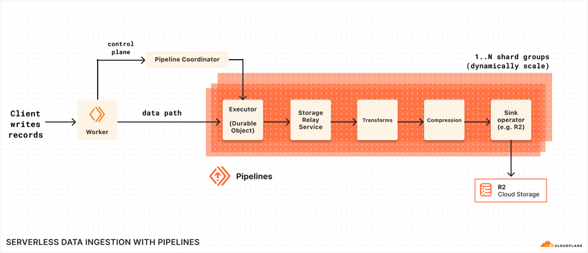
But before you can query your events with Iceberg, they need to be ingested, structured according to a schema, and written into object storage. This is the role of Cloudflare Pipelines.
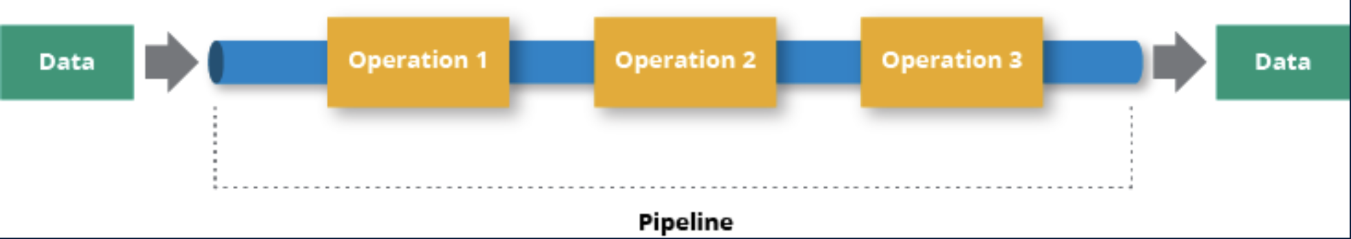
Built on top of Arroyo, a stream processing engine we acquired earlier this year, Pipelines receives events, transforms them with SQL queries, and sinks them to R2 and R2 Data Catalog.
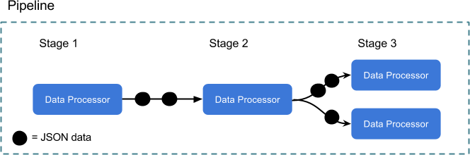
Pipelines is organized around three central objects:
Streams are how you get data into Cloudflare. They’re durable, buffered queues that receive events and store them for processing. Streams can accept events in two ways: via an HTTP endpoint or from a Cloudflare Worker binding.
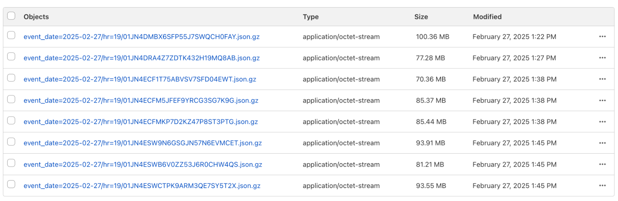
Sinks define the destination for your data. We support ingesting into R2 Data Catalog, as well as writing raw files to R2 as JSON or Apache Parquet. Sinks can be configured to frequently write files, prioritizing low-latency ingestion, or to write less frequent, larger files to get better query performance. In either case, ingestion is exactly-once, which means that we will never duplicate or drop events on their way to R2.
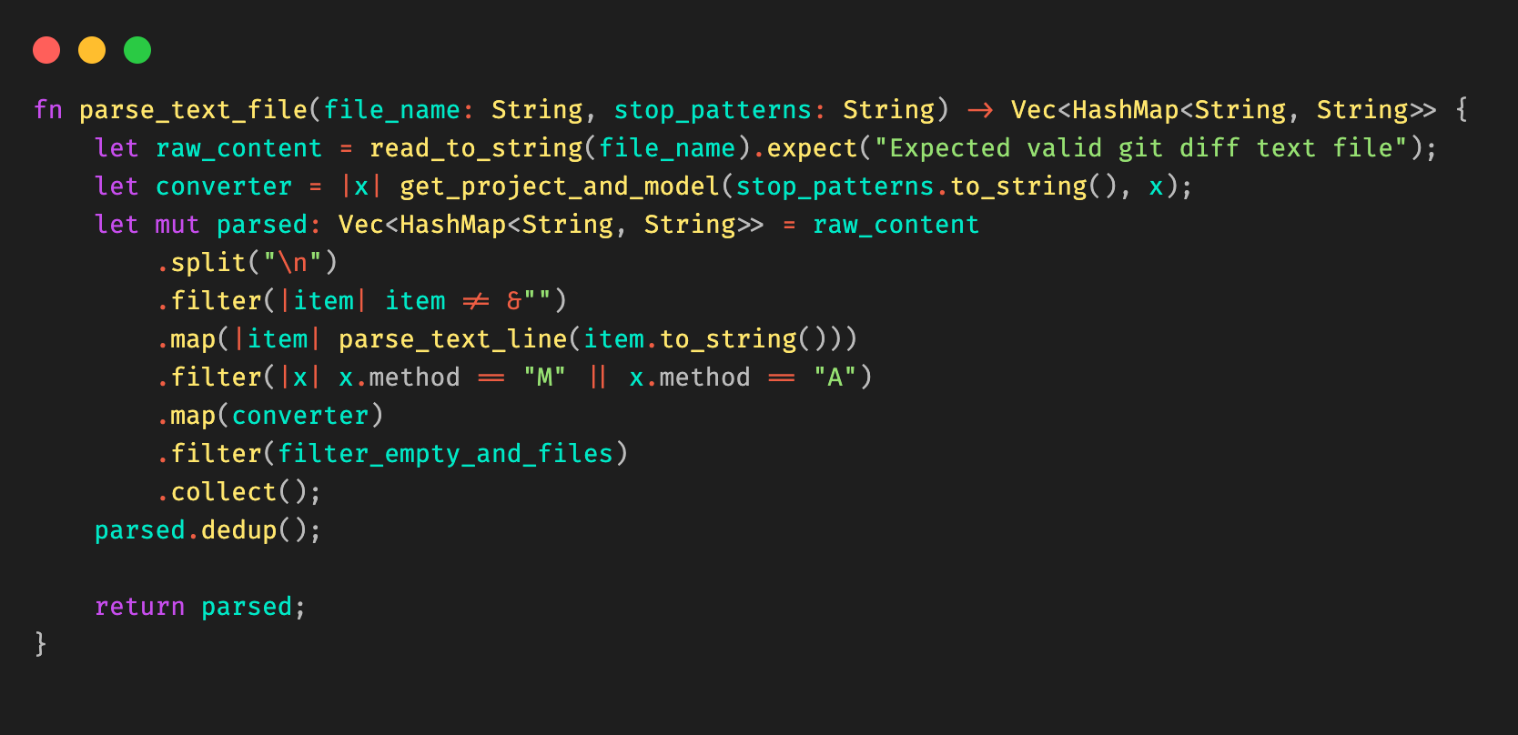
Pipelines connect streams and sinks via SQL transformations, which can modify events before writing them to storage. This enables you to shift left, pushing validation, schematization, and processing to your ingestion layer to make your queries easy, fast, and correct.

For example, here’s a pipeline that ingests events from a clickstream data source and writes them to Iceberg:
INSERT into events_table
SELECT
  user_id,
  lower(event) AS event_type,
  to_timestamp_micros(ts_us) AS event_time,
  regexp_match(url, '^https?://([^/]+)')[1]  AS domain,
  url,
  referrer,
  user_agent
FROM events_json
WHERE event = 'page_view'
  AND NOT regexp_like(user_agent, '(?i)bot|spider');
SQL transformations are very powerful and give you full control over how data is structured and written into the table. For example, you can
-
Schematize and normalize your data, even using JSON functions to extract fields from arbitrary JSON
-
Filter out events or split them into separate tables with their own schemas
-
Redact sensitive information before storage with regexes
-
Unroll nested arrays and objects into separate events
Initially, Pipelines supports stateless transformations. In the future, we’ll leverage more of Arroyo’s stateful processing capabilities to support aggregations, incrementally-updated materialized views, and joins.
Cloudflare Pipelines is available today in open beta. You can create a pipeline using the dashboard, Wrangler, or the REST API. To get started, check out our developer docs.
We aren’t currently billing for Pipelines during the open beta. However, R2 storage and operations incurred by sinks writing data to R2 are billed at standard rates. When we start billing, we anticipate charging based on the amount of data read, the amount of data processed via SQL transformations, and data delivered.
We launched the open beta of R2 Data Catalog in April and have been amazed by the response. Query engines like DuckDB have added native support, and we’ve seen useful integrations like marimo notebooks.
It makes getting started with Iceberg easy. There’s no need to set up a database cluster, connect to object storage, or manage any infrastructure. You can create a catalog with a couple of Wrangler commands:
$ npx wrangler bucket create mycatalog
$ npx wrangler r2 bucket catalog enable mycatalog
This provisions a data lake that can scale to petabytes of storage, queryable by whatever engine you want to use with zero egress fees.
But just storing the data isn’t enough. Over time, as data is ingested, the number of underlying data files that make up a table will grow, leading to slower and slower query performance.
This is a particular problem with low-latency ingestion, where the goal is to have events queryable as quickly as possible. Writing data frequently means the files are smaller, and there are more of them. Each file needed for a query has to be listed, downloaded, and read. The overhead of too many small files can dominate the total query time.
The solution is compaction, a periodic maintenance operation performed automatically by the catalog. Compaction rewrites small files into larger files which reduces metadata overhead and increases query performance.
Today we are launching compaction support in R2 Data Catalog. Enabling it for your catalog is as easy as:
$ npx wrangler r2 bucket catalog compaction enable mycatalogWe’re starting with support for small-file compaction, and will expand to additional compaction strategies in the future. Check out the compaction documentation to learn more about how it works and how to enable it.
At this time, during open beta, we aren’t billing for R2 Data Catalog. Below is our current thinking on future pricing:
|
Pricing* |
|
|
R2 storage For standard storage class |
$0.015 per GB-month (no change) |
|
R2 Class A operations |
$4.50 per million operations (no change) |
|
R2 Class B operations |
$0.36 per million operations (no change) |
|
Data Catalog operations e.g., create table, get table metadata, update table properties |
$9.00 per million catalog operations |
|
Data Catalog compaction data processed |
$0.005 per GB processed $2.00 per million objects processed |
|
Data egress |
$0 (no change, always free) |
*prices subject to change prior to General Availability
We will provide at least 30 days notice before billing starts or if anything changes.
Having data in R2 Data Catalog is only the first step; the real goal is getting insights and value from it. Traditionally, that means setting up and managing DuckDB, Spark, Trino, or another query engine, adding a layer of operational overhead between you and those insights. What if instead you could run queries directly on Cloudflare?
Now you can. We’ve built a query engine specifically designed for R2 Data Catalog and Cloudflare’s edge infrastructure. We call it R2 SQL, and it’s available today as an open beta.
With Wrangler, running a query on an R2 Data Catalog table is as easy as
$ npx wrangler r2 sql query "{WAREHOUSE}" "\
  SELECT user_id, url FROM events \
  WHERE domain = 'mywebsite.com'"
Cloudflare’s ability to schedule compute anywhere on its global network is the foundation of R2 SQL’s design. This lets us process data directly where it lives, instead of requiring you to manage centralized clusters for your analytical workloads.
R2 SQL is tightly integrated with R2 Data Catalog and R2, which allows the query planner to go beyond simple storage scanning and make deep use of the rich statistics stored in the R2 Data Catalog metadata. This provides a powerful foundation for a new class of query optimizations, such as auxiliary indexes or enabling more complex analytical functions in the future.
The result is a fully serverless experience for users. You can focus on your SQL without needing a deep understanding of how the engine operates. If you are interested in how R2 SQL works, the team has written a deep dive into how R2 SQL’s distributed query engine works at scale.
The open beta is an early preview of R2 SQL querying capabilities, and is initially focused around filter queries. Over time, we will be expanding its capabilities to cover more SQL features, like complex aggregations.
We’re excited to see what our users do with R2 SQL. To try it out, see the documentation and tutorials. During the beta, R2 SQL usage is not currently billed, but R2 storage and operations incurred by queries are billed at standard rates. We plan to charge for the volume of data scanned by queries in the future and will provide notice before billing begins.
Today, you can use the Cloudflare Data Platform to ingest events into R2 Data Catalog and query them via R2 SQL. In the first half of 2026, we’ll be expanding on the capabilities in all of these products, including:
-
Integration with Logpush, so you can transform, store, and query your logs directly within Cloudflare
-
User-defined functions via Workers, and stateful processing support for streaming transformations
-
Expanding the featureset of R2 SQL to cover aggregations and joins
In the meantime, you can get started with the Cloudflare Data Platform by following the tutorial to create an end-to-end analytical data system, from ingestion with Pipelines, through storage in R2 Data Catalog, and querying with R2 SQL.
We’re excited to see what you build! Come share your feedback with us on our Developer Discord.