Post Syndicated from Explosm.net original https://explosm.net/comics/a-proposal
New Cyanide and Happiness Comic
Post Syndicated from Explosm.net original https://explosm.net/comics/a-proposal
New Cyanide and Happiness Comic
Post Syndicated from The History Guy: History Deserves to Be Remembered original https://www.youtube.com/watch?v=3b8K1cibbL4
Post Syndicated from Bruce Schneier original https://www.schneier.com/blog/archives/2026/02/ai-found-twelve-new-vulnerabilities-in-openssl.html
The title of the post is”What AI Security Research Looks Like When It Works,” and I agree:
In the latest OpenSSL security release> on January 27, 2026, twelve new zero-day vulnerabilities (meaning unknown to the maintainers at time of disclosure) were announced. Our AI system is responsible for the original discovery of all twelve, each found and responsibly disclosed to the OpenSSL team during the fall and winter of 2025. Of those, 10 were assigned CVE-2025 identifiers and 2 received CVE-2026 identifiers. Adding the 10 to the three we already found in the Fall 2025 release, AISLE is credited for surfacing 13 of 14 OpenSSL CVEs assigned in 2025, and 15 total across both releases. This is a historically unusual concentration for any single research team, let alone an AI-driven one.
These weren’t trivial findings either. They included CVE-2025-15467, a stack buffer overflow in CMS message parsing that’s potentially remotely exploitable without valid key material, and exploits for which have been quickly developed online. OpenSSL rated it HIGH severity; NIST‘s CVSS v3 score is 9.8 out of 10 (CRITICAL, an extremely rare severity rating for such projects). Three of the bugs had been present since 1998-2000, for over a quarter century having been missed by intense machine and human effort alike. One predated OpenSSL itself, inherited from Eric Young’s original SSLeay implementation in the 1990s. All of this in a codebase that has been fuzzed for millions of CPU-hours and audited extensively for over two decades by teams including Google’s.
In five of the twelve cases, our AI system directly proposed the patches that were accepted into the official release.
AI vulnerability finding is changing cybersecurity, faster than expected. This capability will be used by both offense and defense.
More.
Post Syndicated from Nathan Liefting original https://blog.zabbix.com/sending-snmp-traps-from-one-source-to-multiple-zabbix-hosts/31281/

Let’s say you are working in an environment with hundreds or thousands of devices. All of these devices are managed from a nice simple management server, ready for you to configure.
However, you want to start monitoring this stack of devices as well. That could mean hundreds or even thousands of devices to configure.
Not only that, these management servers and associated platforms (usually found on DAS or other Network equipment) often include monitoring tools such as API to discover resources and SNMP to receive traps.
Let’s paint a picture here, as it speaks more than words in these technical setups.
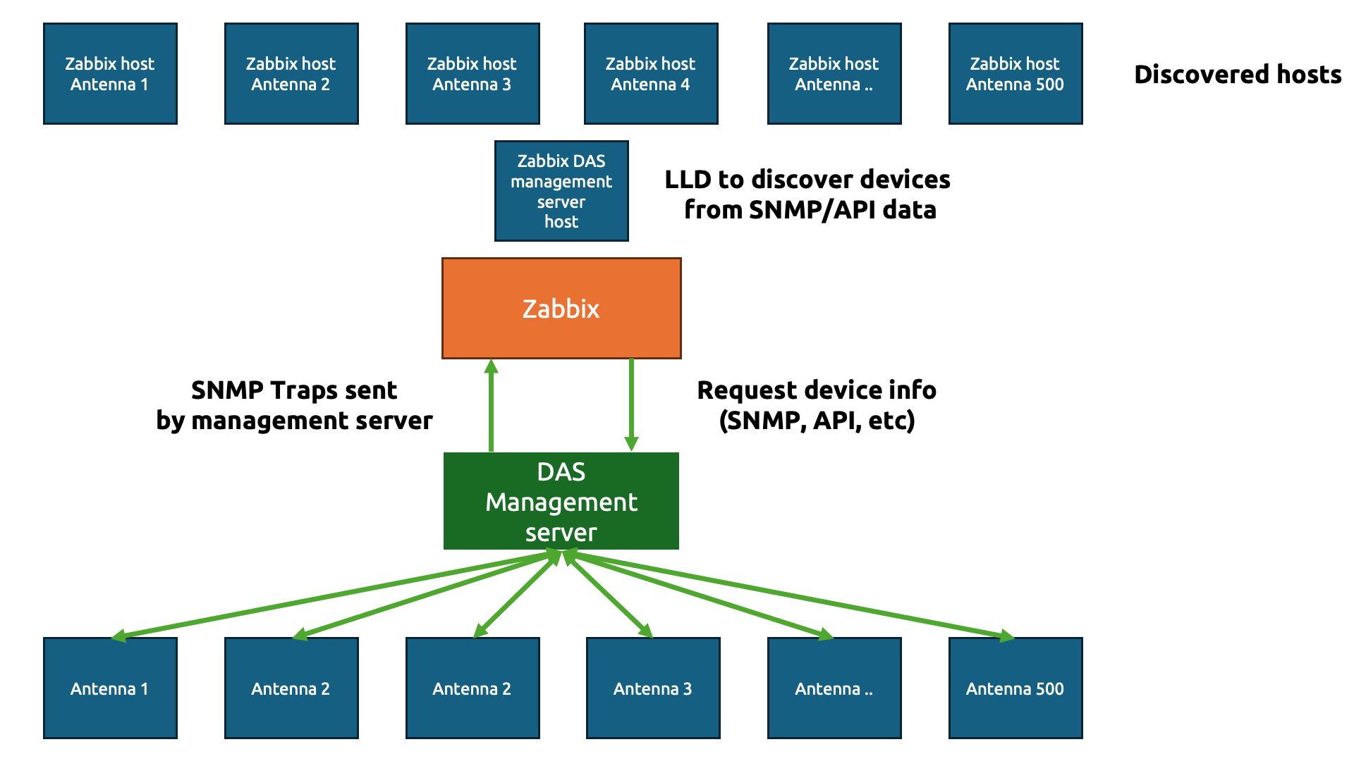
The goal here is simple – we are going to do the usual IT engineer trick and be as lazy as possible to get to the simplest solution (please tell me that isn’t just me!)
We only want to create a simple template (technically two) to gather data from those hundreds or thousands of physical devices. In Zabbix, we start with a template to gather the information about the devices. Let’s say we gather the antenna details using an API and the JSON output looks something like this:
{
"data": [
{
"device_name": "Antenna 1",
"model": "AX-900",
"location": "Roof Sector A",
"serial_number": "SN-A1-001"
},
{
"device_name": "Antenna 2",
"model": "AX-900",
"location": "Roof Sector B",
"serial_number": "SN-A2-002"
},
{
"device_name": "Antenna 3",
"model": "BX-450",
"location": "Basement Level 1",
"serial_number": "SN-A3-003"
}
]
}
Perfect JSON for us to parse through in Zabbix. Now, we need to create our host to collect the DAS management server data first.
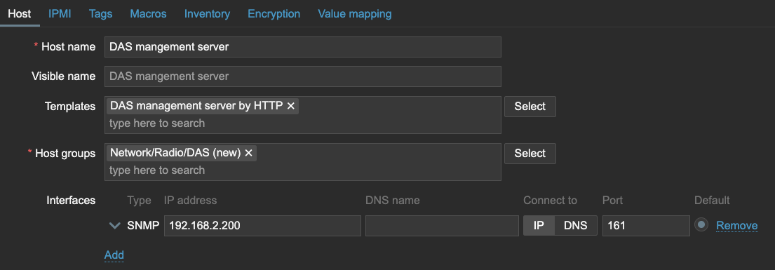
We can use that host to get the data with an item in Zabbix and then send it straight over to Low-Level Discovery.
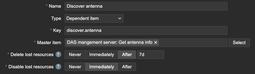
Of course, we need to make sure to capture the name of the antenna devices using JSONPath.

Within this Low-Level Discovery rule, we can then create our Host prototype. Interestingly, since the DAS management server will be sending over all of the data, we should inherit the SNMP interface. All of the Antenna devices will have the same IP address as the DAS management server on this interface, but this will be important later for our SNMP traps.
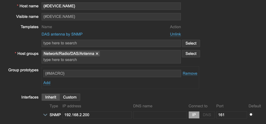
I also want to store the LLD macro {#DEVICE.NAME} as a User macro {$DEVICE.NAME}, which will be important when we create our Antenna template.

Now, let’s see what happens when LLD runs. All of the Antenna are discovered and added to our Zabbix environment. The template DAS Antenna by SNMP is hooked up to the host and all of them have the SNMP interface, just like the DAS management server.

On the template DAS antenna by SNMP, let’s create the SNMP trap item.
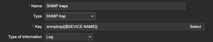
This is where we need the macro we used earlier. The macro will serve as a (part of) the snmptrap item key. Since the SNMP trap items use REGEX to match traps, we can filter only the traps that are related to our device information. We can even extend this further by matching specific OIDs, but only if our Macro is also present after the OID or somewhere else in the trap for example.

The trick here is quite simple. Zabbix matches SNMP trap information based on the IP address.
2025-01-30 10:04:23 2024-01-30
10:04:21 2025-01-30T10:04:21+0200 UDP: [192.168.2.200]:56585->[192.168.2.41]:162
DISMAN-EVENT-MIB::1.3.6.1.5.1.51.1.1 = Antenna 1
As long as the host SNMP IP address matches the IP address within the trap and the REGEX in your SNMP trap item, Zabbix will process the trap, even if it is across 500 hosts. Be careful however, as this also means that you could be duplicating traps if your SNMP trap item REGEX isn’t strict enough.
Another thing is to be mindful of the amount of traps being processed in combination with complex regular expressions. The SNMP trap process within Zabbix server and proxy is a single threaded process. A ticket for improvement is open here.
I hope you enjoyed reading this short example! If you have any questions or need help configuring anything on your Zabbix setup feel free to contact me and the team at Opensource ICT Solutions.
Nathan Liefting

The post Sending SNMP Traps from One Source to Multiple Zabbix Hosts appeared first on Zabbix Blog.
Post Syndicated from The Atlantic original https://www.youtube.com/watch?v=Uplo4EcK110
Post Syndicated from The Atlantic original https://www.youtube.com/watch?v=FSUHZVh-Uzs
Post Syndicated from The Atlantic original https://www.youtube.com/watch?v=eeuS8yc0osc
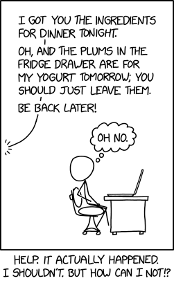
Post Syndicated from xkcd.com original https://xkcd.com/3209/
Post Syndicated from Let's Encrypt original https://letsencrypt.org/2026/02/18/dns-persist-01.html
When you request a certificate from Let’s Encrypt, our servers validate that you control the hostnames in that certificate using ACME challenges. For subscribers who need wildcard certificates or who prefer not to expose infrastructure to the public Internet, the DNS-01 challenge type has long been the only choice. DNS-01 works well. It is widely supported and battle-tested, but it comes with operational costs: DNS propagation delays, recurring DNS updates at renewal time, and automation that often requires distributing DNS credentials throughout your infrastructure.
We are implementing support for a new ACME challenge type, DNS-PERSIST-01, based on a new IETF draft specification. As the name implies, it uses DNS as the validation mechanism, but replaces repeated demonstrations of control with a persistent authorization record bound to a specific ACME account and CA. The draft describes this method as being “particularly suited for environments where traditional challenge methods are impractical, such as IoT deployments, multi-tenant platforms, and scenarios requiring batch certificate operations”.
With DNS-01, validation relies on a one-time token generated by us. Your ACME client publishes a TXT record containing that token at _acme-challenge.<YOUR_DOMAIN>, and we query DNS to confirm that it matches the expected value. Because each authorization requires a new token, DNS updates become part of the issuance workflow. The benefit is that each successful validation provides fresh proof that you currently control DNS for the name being issued.
In practice, this often means DNS API credentials live somewhere in your issuance pipeline, validation attempts involve waiting for DNS propagation, and DNS changes happen frequently — sometimes many times per day in large deployments. Many subscribers accept these tradeoffs, but others would prefer to keep DNS updates and sensitive credentials out of their issuance path.
DNS-PERSIST-01 approaches validation differently. Instead of publishing a new challenge record for each issuance, you publish a standing authorization in the form of a TXT record that identifies both the CA and the specific ACME account you authorize to issue for this domain.
For the hostname example.com, the record would live at _validation-persist.example.com:
_validation-persist.example.com. IN TXT (
  "letsencrypt.org;"
  " accounturi=https://acme-v02.api.letsencrypt.org/acme/acct/1234567890"
)
Once this record exists, it can be reused for new issuance and all subsequent renewals. Operationally, this removes DNS changes from the critical path.
With DNS-01, the sensitive asset is DNS write access. In many deployments, DNS API credentials are distributed throughout issuance and renewal pipelines, increasing the number of places an attacker might compromise them. DNS-PERSIST-01 instead binds authorization directly to an ACME account, allowing DNS write access to remain more tightly controlled after initial setup. The tradeoff is that, because the authorization record persists over time, protecting the ACME account key becomes the central concern.
DNS-PERSIST-01 also introduces explicit scope controls. Without additional parameters, authorization applies only to the validated Fully Qualified Domain Name (FQDN) and remains valid indefinitely.
Adding policy=wildcard broadens the authorization scope to include the validated FQDN, wildcard certificates such as *.example.com, and subdomains whose suffix matches the validated FQDN:
_validation-persist.example.com. IN TXT (
  "letsencrypt.org;"
  " accounturi=https://acme-v02.api.letsencrypt.org/acme/acct/1234567890;"
  " policy=wildcard"
)
Subscribers who aren’t comfortable with authorization persisting indefinitely can include an optional persistUntil timestamp. This limits how long the record may be used for new validations, but also means it must be updated or replaced before it expires. Anyone using this feature should ensure they have adequate reminders or monitoring in place so that authorization does not expire unexpectedly. The timestamp is expressed as UTC seconds since 1970-01-01:
_validation-persist.example.com. IN TXT (
  "letsencrypt.org;"
  " accounturi=https://acme-v02.api.letsencrypt.org/acme/acct/1234567890;"
  " persistUntil=1767225600"
)
Multiple CAs can be simultaneously authorized by publishing multiple TXT records at _validation-persist.<YOUR_DOMAIN>, each containing the issuer-domain-name of the CA you intend to authorize. During validation, each CA queries the same DNS label and evaluates only the records that match its own issuer-domain-name.
The CA/Browser Forum ballot SC-088v3, defining “3.2.2.4.22 DNS TXT Record with Persistent Value”, passed unanimously in October 2025, and the IETF ACME working group adopted the draft that same month. While the document remains an active IETF draft, the core mechanisms described here are not expected to change substantially.
Support for the draft specification is available now in Pebble, a miniature version of Boulder, our production CA software. Work is also in progress on a lego-cli client implementation to make it easier for subscribers to experiment with and adopt. Staging rollout is planned for late Q1 2026, with a production rollout targeted for some time in Q2 2026.
Post Syndicated from Симеон Иванов original https://www.toest.bg/putnata-bezopasnost-otvad-znatsite/

Един ден бях съборен на земята от внезапно отворена автомобилна врата. Шофьорът просто слезе от колата си, без да погледне в огледалото – действие, което би отнело по-малко от секунда, но може да промени нечий ден, а понякога и живот. Инцидентът беше резултат не от агресия или превишена скорост, а от подценяване на риска и липса на изградени навици за внимание.
Тази ситуация ясно показва колко уязвими са пешеходците и велосипедистите и колко често инцидентите възникват не заради грубо нарушение, а поради комбинация от среда, организация на движението и човешко поведение. Именно в резултат на тази случка осъзнах колко важен е системният поглед към пътната безопасност.
Пътната безопасност започва от ежедневните, на пръв поглед дребни решения – несъобразяване с обстановката, недоглеждане при спиране и потегляне, прибързани маневри без достатъчна видимост, непредвиждане на действията на останалите участници в движението или рискови физически действия около автомобила. Именно тези „малки“ пропуски често стоят в основата на тежки последици. Обществено известните трагични случаи – катастрофи с висока скорост в населени места, преминаване на червен сигнал, шофиране след употреба на алкохол или отнемане на предимство на пешеходна пътека – показват, че правилата са били ясни, но съзнателно или поради небрежност са били пренебрегнати. Причината рядко е в липсата на регулации; по-често тя се крие в подценяването на риска, в самоувереността и импулсивните решения зад волана.
Истинската превенция изисква повече от страх от глоба – нужни са зачитане на правилата, активно наблюдение на средата, способност да предвиждаме опасностите и толерантност към останалите на пътя. Възпитаването в нея започва рано: чрез системно обучение по пътна безопасност още в детска възраст, чрез личния пример на родителите и чрез ясни обществени стандарти за поведение. Всеки водач трябва да си зададе прост, но неудобен въпрос: спазвам ли правилата само когато има контрол, или защото осъзнавам, че всяко мое действие може да струва нечий живот? Отговорът му е ключът към реалното намаляване на риска – не новите табели, а личната дисциплина и зрелостта на обществото правят пътя по-безопасен.
Често пътната безопасност се свежда до видими елементи – пътни знаци, маркировка, ограничения на скоростта. Подобно разбиране споделят и експерти от бранша. То обаче е ограничено, защото става въпрос за много по-дълбок и комплексен процес. Реалната безопасност се поражда не от една изолирана мярка – знак, маркирана пешеходна пътека, нови стълбове на светофара или цъфнал прожектор над пешеходната пътека, а от начина, по който всички елементи на транспортната система работят заедно.
Когато липсва синхрон между инфраструктурата, управлението на трафика и реалното човешко поведение, дори формално „правилните“ решения могат да създадат риск. Затова съвременният подход към пътната безопасност стъпва върху две ключови идеи – проактивност и холистично мислене.
Проактивната пътна безопасност означава промяна в начина на мислене. Вместо да реагираме след инцидент (реактивно), трябва да се научим да разпознаваме потенциалните опасности предварително (проактивно). Това включва анализ на конфликтните точки, наблюдение на реалното поведение на участниците в движението и оценка на средата, в която това поведение се осъществява.
В рамките на концепцията за проактивна безопасност акцентът се поставя върху управлението на риска още на етап проектиране, а не върху ограничаването на последствията след настъпване на инцидент. Теорията за самообясняващата се инфраструктура предлага именно такъв превантивен инструментариум, при който пътната среда чрез начина на проектиране на улицата насочва участниците към безопасно поведение.
Например стесняването на пътните ленти в градска среда и прилагането на визуално „успокояване“ на движението (чрез дървесна растителност, паркиране по протежение на улицата или промяна в настилката) водят до естествено намаляване на скоростта, без да е необходим допълнителен контрол. Повдигнатите пешеходни пътеки и кръстовища ограничават риска от тежки инциденти, като физически принуждават водачите да намаляват скоростта в конфликтните точки. Ясното физическо отделяне на велосипедните алеи от автомобилния трафик чрез бордюри или зелени ивици ограничава възможността за странични сблъсъци, а обособяването на трамвайни трасета в самостоятелно платно, трамвайни перони и „виенски спирки“ (каквито например бяха направени на ул. „Алабин“ при бул. „Македония“ в София) елиминира взаимодействието с автомобилния поток.
Допълнително, ограничаването на дългите прави участъци в зони с интензивно пешеходно движение предотвратява неосъзнатото увеличаване на скоростта. По този начин рискът се намалява системно и предварително чрез самата структура на средата, която формира правилни очаквания и поведенчески модели, вместо да се разчита основно на санкции или на последващи компенсаторни мерки.
 Силвия Чакърова

Следващи по вид, но не и по важност инструменти за минимизиране на риска са системите за управление на трафика – светофарите. Често те се възприемат като чисто технически елемент, като поредната спънка по пътя на скоростните отсечки, но влиянието им върху безопасността е силно подценявано. Светофарите не просто регулират потоците – те структурират поведението, създават ритъм и формират очаквания у водачите, пешеходците и велосипедистите.
Добре проектираната светофарна уредба намалява несигурността. Тя ясно определя кой, кога и как преминава, като ограничава импровизацията и рисковите решения. Коректната оптимизация на фазите, междинните времена и координацията между кръстовищата води не само до по-добра пропускателна способност, но и до реално намаляване на пътнотранспортните произшествия, и по-специално на тежките, които са в резултат от несъобразена скорост, за каквато предразполага естествено средата.
Холистичното мислене в пътната безопасност трябва да ни изведе извън рамките на отделния елемент. Инфраструктурата, превозните средства и участниците в движението са взаимнозависими. Често проблемът не е само в шофьора или само в пътя, а става дума за съчетание от фактори.
Разглеждан като жива система, пътят изисква интегриран набор от мерки, които едновременно управляват риска, моделират поведението и отчитат социалния и пространствения контекст. Холистичният подход се основава на разбирането, че безопасността възниква от взаимодействието между инфраструктурата, участниците в движението и градската среда, поради което решенията следва да бъдат системни и взаимно подкрепящи се.
На стратегическо ниво това включва прилагането на концепции като „Безопасна система“ (Safe System Approach) и „Визия нула“ (Vision Zero), в които се приема, че човешките грешки са неизбежни и инфраструктурата трябва да бъде проектирана така, че да не допуска те да водят до фатални последствия. В практическо измерение това се реализира чрез класификация на уличната мрежа според функцията ѝ (например транзитна, разпределителна, локална), като всяка категория има ясно разпознаваем профил и режим на движение.
Сред конкретните пространствени и организационни мерки може да се посочат:
Холистичният подход предполага и координация между транспортно планиране, градоустройство, ландшафтна архитектура и политики за обществено здраве. Озеленяването, активните партерни етажи (например с витрини или с гледащи към улицата балкони), доброто осветление и социалният контрол също допринасят за усещането за безопасност и за реалното намаляване на риска.
В този смисъл пътят не е просто инженерно съоръжение, а динамична градска екосистема, в която устойчивата безопасност се постига чрез съгласувани, последователни и дългосрочни решения.
Като инженер по транспортно строителство и одитор по пътна безопасност мога да кажа, че в одитите често се среща несъгласуваност между различните решения. Например едно кръстовище може да отговаря на всички нормативни изисквания, но ако светофарните фази не отчитат реалните пешеходни потоци или поведението на велосипедистите, рискът остава висок. Холистичният подход изисква не просто спазване на стандартите, а разбиране на реалното използване на пространството.
Светофарните уредби отново са ключов елемент. Те могат и трябва да се адаптират към конкретния контекст – училищни зони, райони с интензивно велосипедно движение или пространства с висока пешеходна активност. Управлението на трафика за мен не е статичен процес, а динамична дейност, която трябва да се развива заедно с града.
Прилагането на утвърдени добри практики в областта на пътната безопасност изисква не само познаване на концепциите, но и прецизно техническо оразмеряване и съобразяване с конкретния контекст. В противен случай съществува риск от формално внедряване на мерки, без да се постигне реален и устойчив ефект.
Една от добрите практики, които смятам за особено ценни в градска среда, е т.нар. самообясняваща се инфраструктура, или Self-Explaining Roads (SER). Това е подход за проектиране на пътната инфраструктура, при който самият път „подсказва“ на водачите как да се държат. Идеята е пътната среда сама да насочва към правилно поведение, без да разчита единствено на знаци и санкции.
Например въвеждането на зони с ограничение до 30 км/ч е доказано ефективно за намаляване на тежестта на произшествията, тъй като при такава скорост вероятността от фатален изход при удар на пешеходец е значително по-ниска, отколкото при 50 км/ч. Практическият резултат обаче зависи и от фактори като широчината на пътя и дали има ограничени прави участъци, повдигнати кръстовища, какви са тротоарите и т.н. Следователно ефективността на мярката зависи от съответствието между регулацията и физическата среда.
Сходна е ситуацията при велосипедните алеи. За да функционират безопасно, те трябва да отговарят на определени условия. В противен случай правилната мярка губи значителна част от потенциала си поради непълна интеграция в мрежата.
Концепцията за споделено пространство (shared space) показва добри резултати в зони с ниска интензивност на движение (през които обикновено преминават под 4000–6000 моторни превозни средства на ден), където взаимодействието между участниците регулира поведението. При участъци с натоварен трафик или при уязвими групи, като хора със зрителни затруднения обаче, липсата на ясно разграничени зони може да доведе до несигурност и повишен субективен риск.
 Ивелина Гаджева

Тези примери показват, че добрите практики не са универсални решения, а инструменти, чиято ефективност зависи от функцията на улицата, интензивността и състава на движението, както и от градската среда. Устойчивото управление на риска изисква техническа обоснованост, последователност и съгласуваност между отделните мерки. Именно осъзнаването на реалните граници на всяка интервенция превръща добрата практика в професионално и дългосрочно решение.
В същото време съм убеден, че няма универсални решения. Адаптивните системи за управление на трафика имат огромен потенциал, но изискват качествени данни, постоянна поддръжка и добре обучени специалисти. Без тези условия те могат да загубят своята ефективност или дори да създадат нови конфликтни ситуации. Затова всяко решение трябва да бъде оценявано спрямо конкретния контекст, а не прилагано механично.
Дори най-добре проектираната система не може да предотврати изцяло инцидентите. Затова вторият основен стълб на съвременната пътна безопасност е минимизирането на последствията. Това включва както пасивната безопасност на превозните средства (например въздушни възглавници, системи за следене на дистанцията до предния автомобил, следене на пътните ленти и знаци и пр.), така и инфраструктурни решения, които ограничават енергията на сблъсъка.
В контекста на проактивната безопасност и системния подход към проектирането следва да се разглеждат и инфраструктурни решения, които целенасочено ограничават енергията на сблъсъка. Дори сравнително малко намаляване на скоростта води до съществено редуциране на енергията, която се предава върху човешкото тяло при удар. Следователно ролята на инфраструктурата не е единствено да предотвратява конфликти, но и да ограничава последствията в случаите, когато грешки все пак настъпят.
Ограничаването на енергията на сблъсъка може да се постигне и чрез пространствено разделяне на потоците, както вече стана дума по-горе. Физическото отделяне на велосипедисти и пешеходци от автомобилното движение, обособяването на трамвайни трасета или прилагането на средни разделителни ивици намаляват вероятността от директен страничен или челeн удар с голяма сила. Кръговите кръстовища трансформират потенциалните челни конфликти в странични – с по-ниска относителна скорост и по-лек удар.
Допълнителен аспект е използването на елементи като еластични огради (мантинели), ударопоглъщащи буфери пред твърди препятствия. Управлението на трафика и светофарните уредби са сред най-мощните инструменти за намаляване на риска, когато се използват професионално и в синергия с останалите елементи на уличната инфраструктура.
По този начин инфраструктурата става активен инструмент за намаляване на силата на удара. Тя не разчита единствено на предотвратяване на грешки, а приема тяхната неизбежност и цели да поддържа силата на евентуалния сблъсък в граници, които минимизират тежките и фаталните последствия. Именно това разбиране е в основата на съвременните подходи към устойчив модел на безопасност.
проактивната и холистична система за пътна безопасност не е абстрактна концепция, а необходимост. Тя изисква експертно мислене, последователност и дълбоко разбиране на човешкото поведение.
В крайна сметка безопасността на пътя не зависи от един знак или една система, а от качеството на цялостния подход – от начина, по който планираме, проектираме и управляваме движението, и от отговорността, която носим като специалисти и участници в тази обща система.
В настоящата ни съвместна поредица с „Екипът на София“ обсъждаме планирането, озеленяването, архитектурата, инфраструктурата, мобилността и още много други градски теми, описваме добрите примери и търсим възможните решения за подобряването на качеството на живот в нашите градове.

Post Syndicated from The Atlantic original https://www.youtube.com/shorts/DeZTHZtre9Q
Post Syndicated from Felix John original https://aws.amazon.com/blogs/big-data/amazon-managed-service-for-apache-flink-application-lifecycle-management-with-terraform/
In this post, you’ll learn how to use Terraform to automate and streamline your Apache Flink application lifecycle management on Amazon Managed Service for Apache Flink. We’ll walk you through the complete lifecycle including deployment, updates, scaling, and troubleshooting common issues.
Managing Apache Flink applications through their entire lifecycle from initial deployment to scaling or updating can be complex and error-prone when done manually. Teams often struggle with inconsistent deployments across environments, difficulty tracking configuration changes over time, and complex rollback procedures when issues arise.
Infrastructure as Code (IaC) addresses these challenges by treating infrastructure configuration as code that can be versioned, tested, and automated. While there are different IaC tools available including AWS CloudFormation or AWS Cloud Development Kit (AWS CDK), we focus on HashiCorp Terraform to automate the complete lifecycle management of Apache Flink applications on Amazon Managed Service for Apache Flink.
Managed Service for Apache Flink allows you to run Apache Flink jobs at scale without worrying about managing clusters and provisioning resources. You can focus on developing your Apache Flink using your Integrated Development Environment (IDE) of choice, building and packaging the application using standard build and CI/CD tools. Once your application is packaged and uploaded to Amazon S3, you can deploy and run it with a serverless experience.
While you can control your Managed Service for Apache Flink applications directly using the AWS Console, CLI, or SDKs, Terraform provides key advantages such as version control of your application configuration, consistency across environments, and seamless CI/CD integration. This post builds upon our two-part blog series “Deep dive into the Amazon Managed Service for Apache Flink application lifecycle – Part 1” and “Part 2” that discusses the general lifecycle concepts of Apache Flink applications.
We use the sample code published on the GitHub repository to demonstrate the lifecycle management. Note that this is not a production-ready solution.
Before you can manage your Apache Flink applications with Terraform, you need to set up your execution environment. In this section, we’ll cover how to configure Terraform state management and credential handling. The Terraform AWS provider supports Managed Service for Apache Flink through the aws_kinesis_analyticsv2_application resource (using the legacy name “Kinesis Analytics V2“).
Terraform uses a state file to track the resources it manages. In Terraform, storing the state file in Amazon S3 is a best practice for teams working collaboratively because it provides a centralised, durable, and secure location for tracking infrastructure changes. However, since multiple engineers or CI/CD pipelines may run Terraform simultaneously, state locking is essential to prevent race conditions where concurrent executions could corrupt the state. S3 as backend is commonly used for state storage and locking, ensuring that only one Terraform process can modify the state at a time, thus maintaining infrastructure consistency and avoiding deployment conflicts.
To run Terraform inside a Docker container while ensuring that it has access to the necessary AWS credentials and infrastructure code, we follow a structured approach. This process involves exporting AWS credentials, mounting required directories, and executing Terraform commands inside a Docker container. Let’s break this down step by step. Before running Terraform, we need to make sure that our Docker container has access to the required AWS credentials. Since we are using temporary credentials, we generate them using the AWS CLI with the following command:
aws configure export-credentials --profile $AWS_PROFILE --format env-no-export > .env.dockerThis command does the following:
$AWS_PROFILE)..env.docker in a format suitable for Docker.--format env-no-export option displays credentials as non-exported shell variablesThis file (.env.docker) will later be used to pass credentials into the Docker container
Running Terraform inside a Docker container provides a consistent, portable, and isolated environment for managing infrastructure without requiring Terraform to be installed directly on the local machine. This approach ensures that Terraform runs in a controlled environment, reducing dependency conflicts and improving security. To execute Terraform within a Docker container, we use a docker run command that mounts the necessary directories and passes AWS credentials, allowing Terraform to apply infrastructure changes seamlessly.
The Terraform configuration files are stored in a local terraform folder, which is virtually attached to the container using the -v flag. This allows the containerised Terraform instance to access and modify infrastructure code as if it were running locally.
To run Terraform in Docker, the following command is executed:
Breaking down this command step by step:
--env-file .env.docker provides the AWS credentials required for Terraform to authenticate.--rm -it runs the container interactively and is removed after execution to prevent clutter.-v ./terraform:/home/flink-project/terraform mounts the Terraform directory into the container, making the configuration files accessible.-v ./build.sh:/home/flink-project/build.sh mounts the build.sh script, which contains the logic to build JAR file for flink and execute Terraform commands.msf-terraform is the Docker image used, which has Terraform pre-installed.bash build.sh apply runs the build.sh script inside the container, passing apply as an argument to trigger the Terraform apply process.Inside the container, build.sh typically includes commands such as terraform init to initialise the Terraform working directory and terraform apply to apply infrastructure changes. Since the Terraform execution happens entirely within the container, there is no need to install Terraform locally, and the process remains consistent across different systems. This method is particularly beneficial for teams working in collaborative environments, as it standardises Terraform execution and allows for reproducibility across development, staging, and production environments.
In this section, we walk through each phase of the Apache Flink application lifecycle and understand how you can implement these operations using Terraform. While these operations are usually fully automated as part of a CI/CD pipeline, you will execute the individual steps manually from the command line for demonstration purposes. There are many ways to run Terraform depending on your organization’s tooling and infrastructure setup, but for this demonstration, we run Terraform in a container alongside the application build to simplify dependency management. In real-world scenarios, you would typically have separate CI/CD stages for building your application and deploying with Terraform, with distinct configurations for each environment. Since every organization has different CI/CD tooling and approaches, we keep these implementation details out of scope and focus on the core Terraform operations.
For a comprehensive deep dive into Apache Flink application lifecycle operations, refer to our previous two-part blog series.
To get started you want to create your Apache Flink application running on Managed Service for Apache Flink. You should execute the following Docker command:
This command will complete the following operations by executing the bash script build.sh:
terraform/config.tfvars.jsonterraform applyTerraform fully covers this operation. You can check the running Apache Flink application using AWS CLI or inside the Managed Apache Flink Console after Terraform completes with Apply Complete! Terraform is expecting the Apache Flink artifact, i.e. the JAR file to be packaged and copied to S3. This operation is usually part of the CI/CD pipeline and executed before invoking the terraform apply. Here, the operation is specified in the build.sh script.
You have successfully created and started the Flink application. However, you realize that you have to make a change to the Flink application code. Let’s make a code change to the application code in flink/ and see how to build and deploy it. After making the necessary changes, you simply have to run the following Docker command again that builds the JAR file, uploads it to S3 and deploys the Apache Flink application using Terraform:
This phase of the lifecycle is fully supported by Terraform as long as both applications are state compatible, meaning that the operators of the upgraded Apache Flink application are able to restore the state from the snapshot that is taken from the old application version, before Managed Service for Apache Flink stops and deploys the change. For example, removing a stateful operator without enabling the allowNonRestoredState flag or changing an operator’s UID could prevent the new application from restoring from the snapshot. For more information on state compatibility, refer to Upgrading Applications and Flink Versions. For an example of state incompatibility, and strategies for handling state incompatibility, refer to Introducing the new Amazon Kinesis source connector for Apache Flink.
You also need to be careful with deploying code changes that contain bugs preventing the Apache Flink job from starting. For more information, refer to failure mode (a) – a problem prevents the application code from being deployed under When starting or updating the application goes wrong. For instance, this can be simulated by setting the mainClass in flink/pom.xml mistakenly to com.amazonaws.services.msf.WrongJob. Similar to before you build the JAR, upload it and run the terraform apply by running the Docker command from above. However, Terraform now fails to correctly apply the changes and throws an error message as the Apache Flink application fails to correctly update. Finally, the application status moves to READY.

To remedy the issue, you have to change the value of mainClass back to the original one and deploy the changes to Managed Service for Apache Flink. The Apache Flink application remains in READY status and doesn’t start automatically, as this was its state before applying the fix. Note that Terraform does not try to start the application when you deploy a change. You will have to manually start the Flink application using the AWS CLI or through the Managed Apache Flink Console.
As detailed in Part 2 of the companion blog, there is a second failure scenario where the application starts successfully, but the job becomes stuck in a continuous fail-and-restart loop. A code change can also cause this failure mode. We will cover the second error scenario when we cover deploying configuration changes.
As part of the lifecycle management of your Apache Flink application, you may need to explicitly rollback to a previous running application version. This is particularly useful when a newly deployed application version with application code changes exhibits unexpected behaviour and you want to explicitly rollback the application. Currently, Terraform does not support explicit rollbacks of your Apache Flink application running in Managed Service for Apache Flink. You will have to resort to therollbackApplication API through the AWS CLI or the Managed Service for Apache Flink Console to revert the application to the previous running version.
When you perform the explicit rollback, Terraform will initially not be aware of the changes. More specifically, the S3 path to the JAR file in the Managed Service for Apache Flink service (see left part of the image below) is different to the S3 path denoted in the terraform.tfstate file stored in Amazon S3 (see the right part of the image below). Fortunately, Terraform will always perform refreshing actions that include reading the current settings from all managed remote objects and updating the Terraform state to match as part of creating a plan in both terraform plan and terraform apply commands.
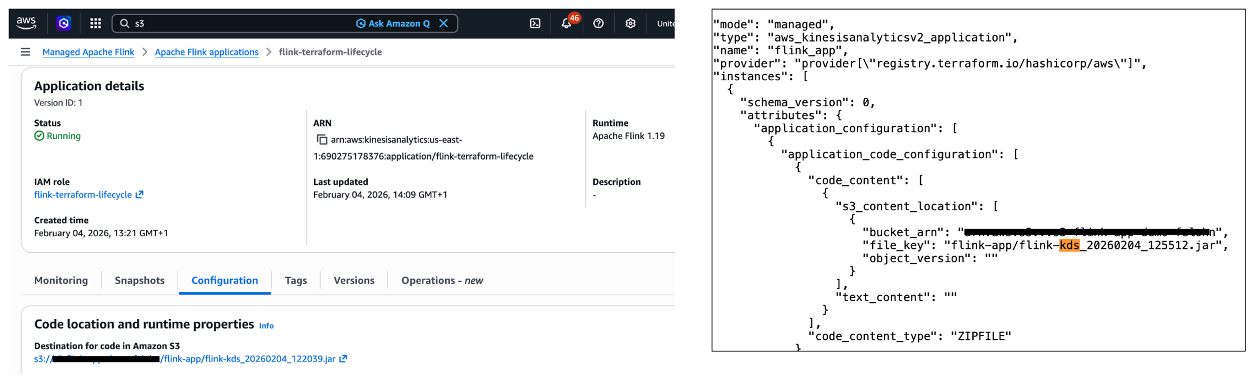
In summary, while you can not perform a manual rollback using Terraform, Terraform will automatically refresh the state when deploying a change using terraform apply.
You have already made changes to the application code of your Apache Flink application. What about making changes to the config of the application, e.g., changing runtime parameters? Imagine you want to change the application logging level of your running Apache Flink application. To change the logging level from ERROR to INFO, you have to change the value for flink_app_monitoring_metrics_level in the terraform/config.tfvars.json to INFO. To deploy the config changes, you need to run the docker run command again as done in the previous sections. This scenario works as expected and is fully covered by Terraform.
What happens when the Apache Flink application deploys successfully but fails and restarts during execution? For more information, please refer to failure mode (b) – the application is started, the job is stuck in a fail-and-restart loop under When starting or updating the application goes wrong. Note that this failure mode can happen when making code changes as well.
In the following example, we apply a wrong configuration change preventing the Kinesis connector from initialising correctly, ultimately putting the job in a fail-and-restart loop. To simulate this failure scenario, you’ll need to modify the Kinesis stream configuration by changing the stream name to a non-existent one. This change is made in the terraform/config.tfvars.json file, specifically altering the stream.name value under flink_app_environment_variables. When you deploy with this invalid configuration, the initial deployment will appear successful, showing an Apply Complete! message. The Flink application status will also show as RUNNING. However, the actual behaviour reveals problems. If you check the Flink Dashboard, you’ll see the application is continuously failing and restarting. Also, you will see a warning message about the application requiring attention in the AWS Console.
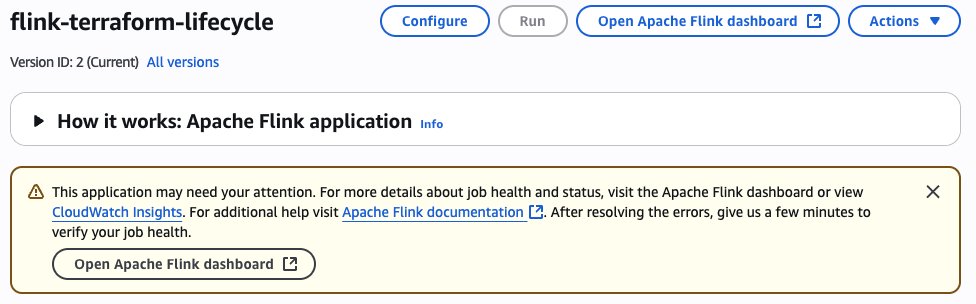
As detailed in the section Monitoring Apache Flink application operations in the companion blog (part 2), you can monitor the FullRestarts metric to detect the fail-and-restart loop.
Reverting the changes made to the environment variable and deploying the changes will result in Terraform showing the following error message: Failed to take snapshot for the application flink-terraform-lifecycle at this moment. The application is currently experiencing downtime.

You have to force-stop without a snapshot and restart the application with a snapshot to get your Flink application back to a properly functioning state. You should constantly monitor the application state of your Apache Flink application to detect any issues.
Another common operation in the lifecycle of your Apache Flink application is scaling the application up or down by adjusting the parallelism. This operation changes the number of Kinesis Processing Units (KPUs) allocated to your application. Let’s look at two different scaling scenarios and how they are handled by Terraform.
In the first scenario, you want to change the parallelism of your running Apache Flink application within the default parallelism quota. To do this, you need to modify the value for flink_app_parallelism in the terraform/config.tfvars.json file. After updating the parallelism value, you deploy the changes by running the Docker command as done in the previous sections:
This scenario works as expected and is fully covered by Terraform. The application will be updated with the new parallelism setting, and Managed Service for Apache Flink will adjust the allocated KPUs accordingly. Note that there is a default quota of 64 KPUs for a single Managed Service for Apache Flink application, which must be raised proactively via a quota increase request if you need to scale your Managed Service for Apache Flink application beyond 64 KPUs. For more information, refer to Managed Service for Apache Flink quota.
Less common change deployments which require special handling In this section we analyze some less common change deployment scenarios which require some special handling.
Removing an operator from your Apache Flink application requires special consideration, particularly regarding state management. When you remove an operator, the state from that operator still exists in the latest snapshot, but there’s no longer a corresponding operator to restore it. Let’s take a closer look at this scenario and understand how you can handle it properly. First, you need to make sure that the parameter AllowNonRestoredState is set to True. This parameter specifies whether the runtime is allowed to skip a state that cannot be mapped to the new program, when restoring from a snapshot. Allowing non-restored state is required to successfully update an Apache Flink application when you dropped an operator. To enable the AllowNonRestoredState, you need to set the configuration value for flink_app_allow_non_restored_state to true in terraform/config.tfvars.json. Then, you can go ahead and remove an operator: For example, you can directly have the sourceStream write to the sink connector in flink/src/main/java/com/amazonaws/services/msf/StreamingJob.java. Change code line 146 from windowedStream.sinkTo(sink).uid("kinesis-sink")to sourceStream.sinkTo(sink).uid("kinesis-sink"). Make sure that you have commented out the entire windowedStream code block (lines 103 to 140).
This change will remove the windowed computation and directly connect the source stream to the sink, effectively removing the stateful operation. After removing the operator from your Flink application code, you deploy the changes using the Docker command as previously done. However, the deployment fails with the following error message: Could not execute application. As a result, the Apache Flink application moves to the READY state. To recover from this situation, you need to restart the Apache Flink application using the latest snapshot for the application to successfully start and move to RUNNING status. Importantly, you need to make sure that AllowNonRestoredState is enabled. Otherwise, the application will fail to start as it cannot restore the state for the removed operator.
During the lifecycle management of your Apache Flink application, you might encounter scenarios where code changes break state compatibility. This typically happens when you modify stateful operators in ways that prevent them from restoring their state from previous snapshots.
A common example of breaking state compatibility is changing the UID of a stateful operator (such as an aggregation or windowing operator) in your application code. To safeguard against such breaking changes, you can enable the automatic system rollback feature in Managed Service for Apache Flink as described in the subsection Rollback under Lifecycle of an application in Managed Service for Apache Flink previously. This feature is disabled by default and can be enabled using the AWS Management Console or invoking the UpdateApplication API operation. There is no way in Terraform to enable system rollback.
Next, let’s demonstrate this by breaking the state compatibility of your Apache Flink application by changing the UID of a stateful operator, e.g., the string windowed-avg-price in line 140 of flink/src/main/java/com/amazonaws/services/msf/StreamingJob.java to windowed-avg-price-v2 and deploy the changes as before. You will encounter the following error:
Error: waiting for Kinesis Analytics v2 Application (flink-terraform-lifecycle) operation (*) success: unexpected state ‘FAILED’, wanted target ‘SUCCESSFUL’. last error: org.apache.flink.runtime.rest.handler.RestHandlerException: Could not execute application.
At this point, Managed Service for Apache Flink automatically rolls back the application to the previous snapshot with the previous JAR file, maintaining your application’s availability as you have enabled system-rollback capability. Terraform will initially be not aware of the performed rollback. Fortunately, as we have already witnessed in subsection Manual rollback application code to previous application code, Terraform will automatically refresh the state when we change UID to the previous value and deploy the changes.
Managed Service for Apache Flink supports in-place upgrade to new Flink runtime versions. See the documentation for more details. Updating the application dependencies and any required code changes is a responsibility of the user. Once you have updated the code artifact, the service is able to upgrade the runtime of your running application in-place, without data loss. Let’s examine how Terraform handles Flink version upgrades.
To upgrade your Apache Flink application from version 1.19.1 to 1.20, you need to:
flink/pom.xml to version 1.20.0 (flink.version to 1.20.1 and flink.connector.version to 5.0.0-1.20 in <properties>)flink_app_runtime_environment to FLINK-1_20 in terraform/config.tfvars.jsondocker run commandTerraform successfully performs an in-place upgrade of your Flink application. You will receive the following message: Apply complete! Resources: 0 added, 1 changed, 0 destroyed.
Let’s take a closer look at operations that are currently not supported by Terraform.
Terraform provides the start_application parameter, indicating whether to start or stop the application. You can set this parameter using flink_app_start in config.tfvars.json to stop your running Apache Flink application. However, this will only work if the current configuration value is set to true. In other words, Terraform only responds to the change in the parameter value, not the absolute value itself. After Terraform applies this change, your Apache Flink application will stop and its application status will move to READY. Similarly, restarting the application requires changing the flink_app_start value back to true, but this will only take effect if the current configuration value is false. Terraform will then restart your application, moving it back to the RUNNING state.
In summary, you cannot start or stop your Apache Flink application without making any configuration change in Terraform. You have to use AWS CLI, AWS SDK or AWS Console to start or stop your application.
Similar to the previous section, Terraform requires an actual configuration change of application_restore_type to trigger a restart with different snapshot settings. Simply reapplying the same configuration values won’t initiate a restart from a different snapshot or no snapshot. You have to use AWS CLI, AWS SDK or AWS Console to restart your application from an older snapshot.
Terraform does not support performing a manual rollback nor automatic system rollback. In addition, Terraform will also not be aware when such a rollback is taking place. The state information will be outdated, e.g. S3 path information. However, Terraform automatically performs refreshing actions to read settings from all managed remote objects and updates the Terraform state to match. Consequently, you can have Terraform refresh the Terraform state by successfully running a terraform apply command.
In this post, we demonstrated how to use Terraform to automate the lifecycle management of your Apache Flink applications on Managed Service for Apache Flink. We walked through fundamental operations including creating, updating, and scaling applications, explored how Terraform handles various failure scenarios and examined advanced scenarios such as removing operators and performing in-place runtime upgrades. We also identified operations that are currently not supported by Terraform.
For more information, see Run a Managed Service for Apache Flink application and our two-part blog on Deep dive into the Amazon Managed Service for Apache Flink application lifecycle.
Post Syndicated from Anirudh Chawla original https://aws.amazon.com/blogs/big-data/build-a-data-pipeline-from-google-search-console-to-amazon-redshift-using-aws-glue/
Google Search Console (GSC) is a service offered by Google that helps you monitor, maintain, and troubleshoot your site’s presence in Google Search results. It provides you unique insights directly from Google about how the search engine sees your site, helping you improve your performance in Search Engine Results Pages (SERPs).
When there is a need to merge Google Search Console data with multiple data sources or conduct complex performance analysis, traditional methods can become time-consuming and error-prone. This is where Amazon Redshift and AWS Glue offer a comprehensive data integration solution.
In this post, we explore how AWS Glue extract, transform, and load (ETL) capabilities connect Google applications and Amazon Redshift, helping you unlock deeper insights and drive data-informed decisions through automated data pipeline management. We walk you through the process of using AWS Glue to integrate data from Google Search Console and write it to Amazon Redshift.
AWS Glue is a serverless data integration service that helps discover, prepare, and combine data for analytics, machine learning (ML), and application development. You can use AWS Glue to create, run, and monitor data integration and ETL pipelines and catalog your assets across multiple data stores.
Amazon Redshift is a fast, scalable, and fully managed cloud data warehouse that lets you to process and run complex SQL analytics workloads on structured and semi-structured data. It also helps you securely access your data in operational databases, data lakes, or third-party datasets with minimal movement or copying of data. Tens of thousands of customers use Amazon Redshift to process large amounts of data, modernize their data analytics workloads, and provide insights for their business users.
The following diagram illustrates the architecture that we implement in this post.
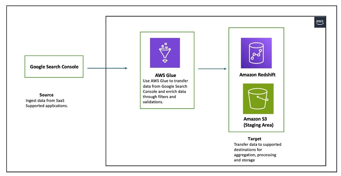
The workflow consists of an AWS Glue job reading data from Google Search Console for the three entities that Google Search Console supports (Search Analytics, Sites, and Sitemaps), and writing the data in a Redshift provisioned cluster. AWS Glue supports Google Search Console API v3.
In the following sections, we walk through the following steps to configure AWS Glue to set up a connection between Google Search Console and Amazon Redshift for data migration:
Before starting this walkthrough, you must have the following prerequisites in place:
To connect to Google Search Console, AWS Glue requires OAuth 2.0 for authentication. You must create an OAuth 2.0 client ID, which AWS Glue uses when requesting an OAuth 2.0 access token. To create an OAuth 2.0 client ID in the Google Cloud Platform console, follow these steps:
You can use AWS Glue to transfer data from supported sources into your Redshift databases. You need an IAM role because AWS Glue needs authorization to write into Redshift databases. To create a role, complete the following steps:
Modify the S3 bucket name that you are using as the staging bucket. Additionally, AWS Glue must have access to specific AWS owned S3 buckets for hosting AWS Glue transforms. In this example, the IAM policy uses aws-glue-studio-transforms-510798373988-prod-us-east-1, which is the AWS owned bucket in the us-east-1 Region. Refer to Review IAM permissions needed for ETL jobs for the appropriate bucket name for your Region.
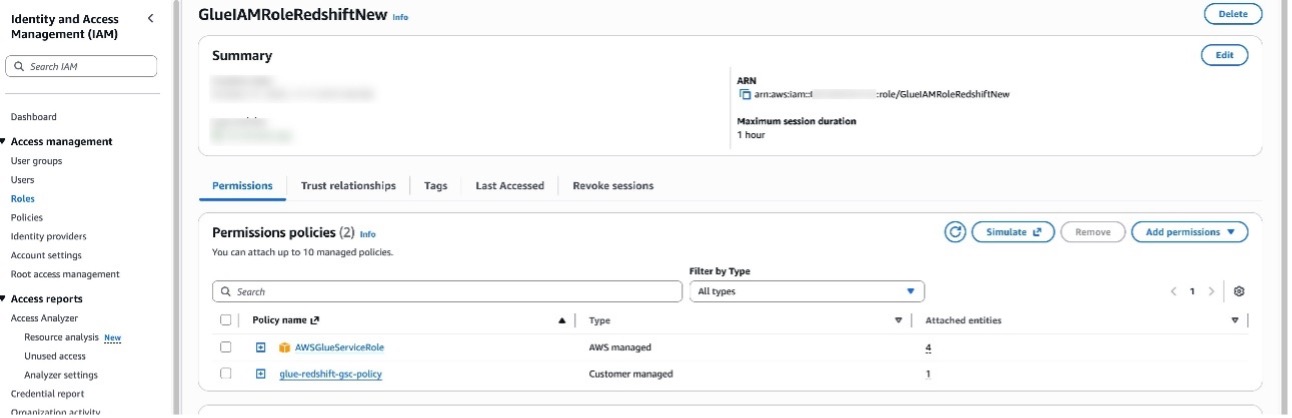
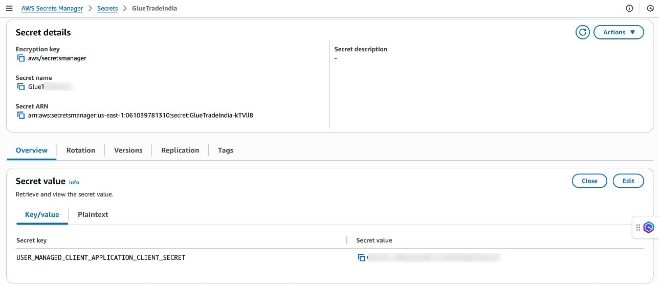
Complete the following steps to create a Secrets Manager secret:
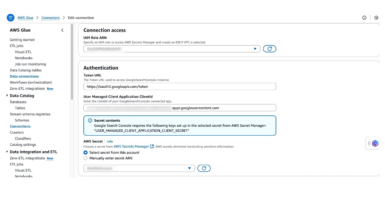
To create a connection to Google Search Console in AWS Glue, follow these steps:
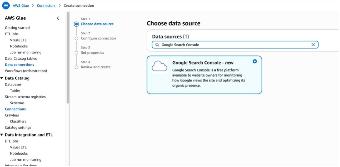
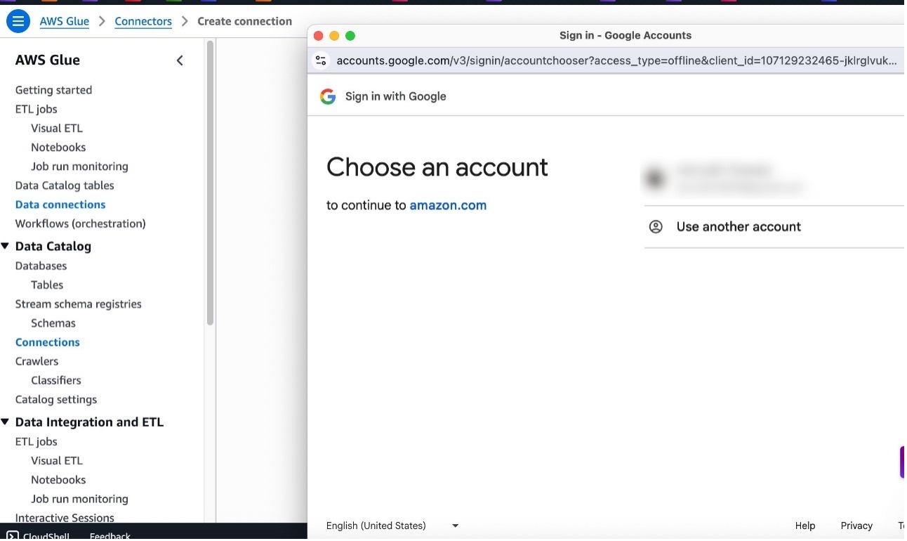
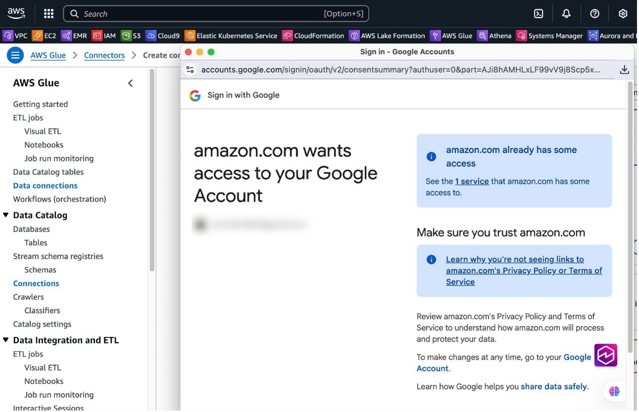
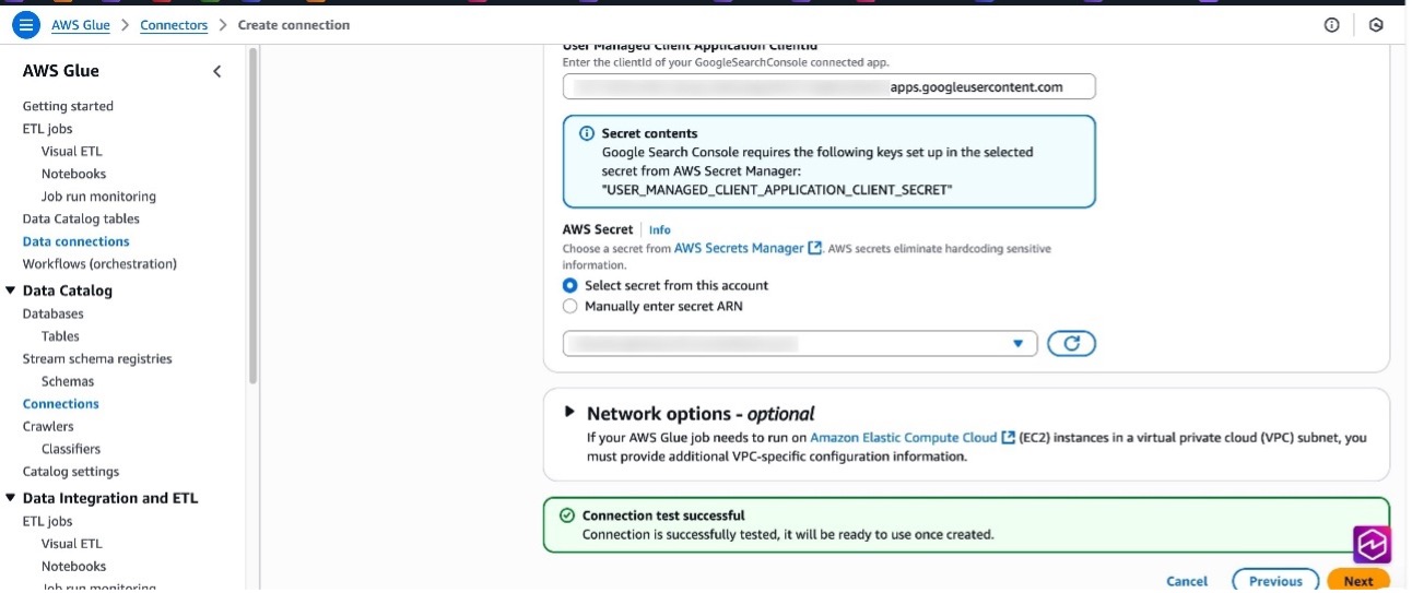
If the user has authorized access, the connection test will be successful.
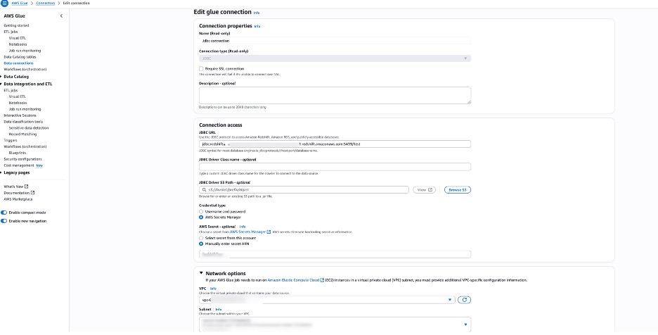
Complete the following steps to set up an AWS Glue connection for Amazon Redshift. Refer to Redshift connections for more information.
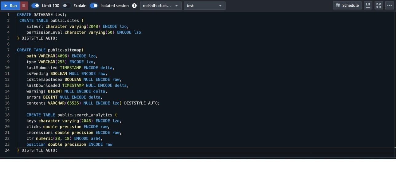
To set up table and permissions in Amazon Redshift, follow these steps:
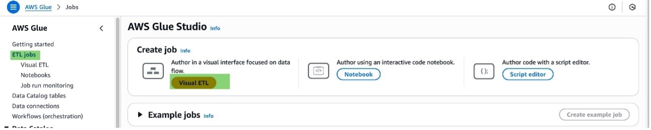
To create a data flow in AWS Glue, follow these steps:
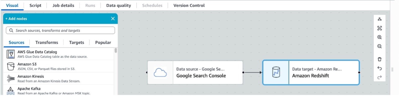
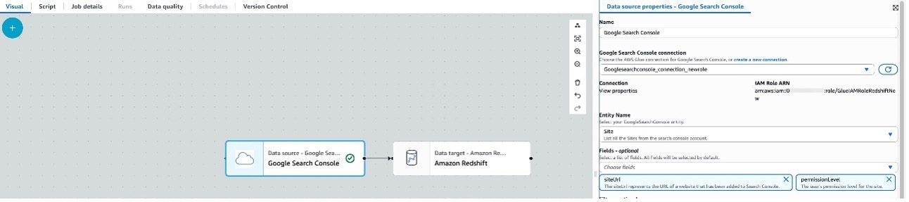
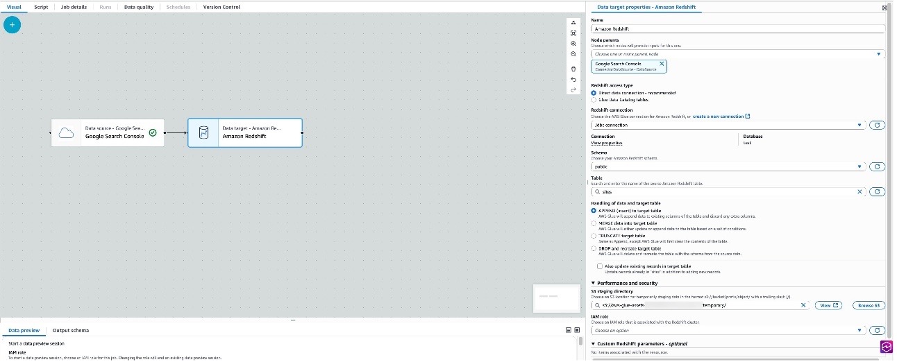

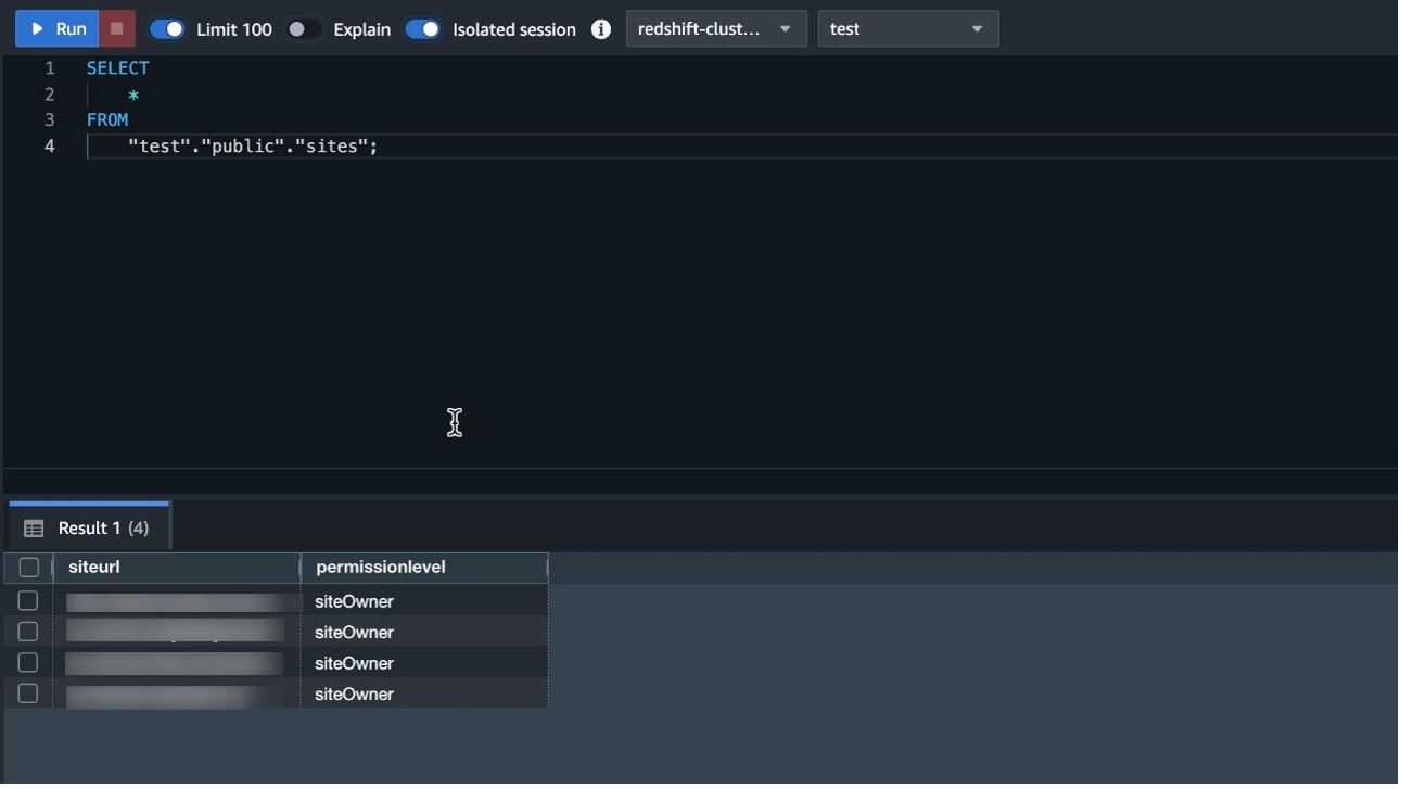
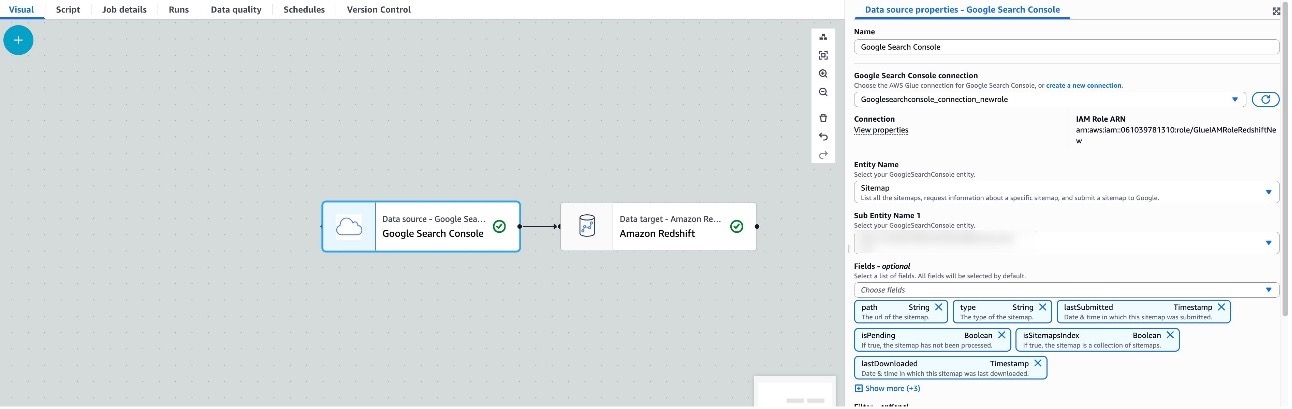
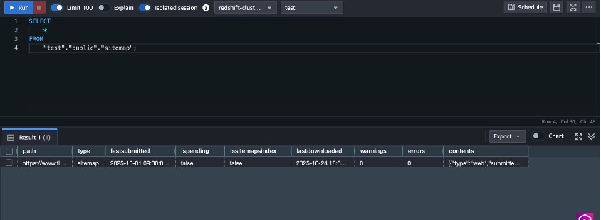
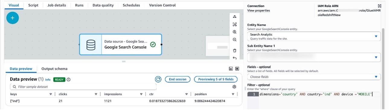
The Search Analytics entity provides support for multiple filters that can be used to view the traffic data for the sites. The following examples show use of some filter predicates you can use that Google Search Console connections support.
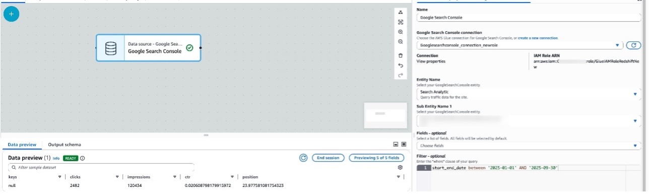
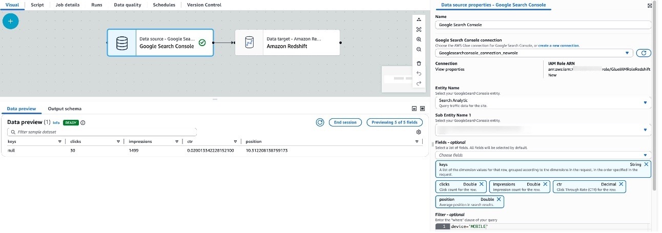
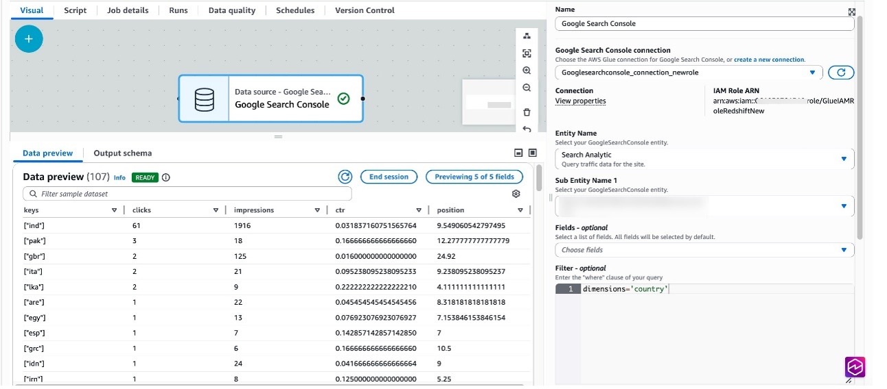
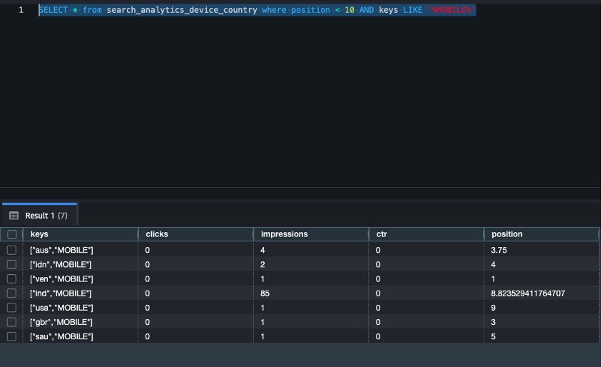
In this section, we run analytical queries using aggregated data across different search entities.
List all countries where site position is less than 10 and device type is MOBILE:
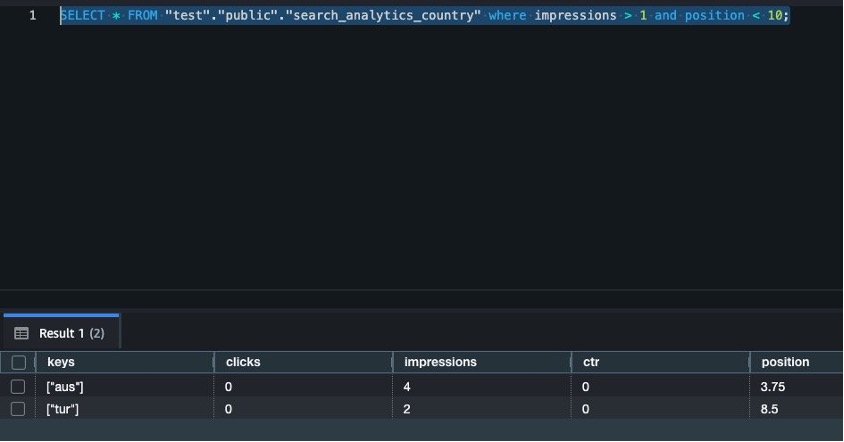
List all countries where impressions are greater than 1 and position is less than 10:
To avoid incurring charges, clean up the resources in your AWS account by completing the following steps:
In this post, we walked you through the process of using AWS Glue to integrate data from Google Search Console and write it to Amazon Redshift, a petabyte-scale data warehouse. Whether you’re archiving historical data, performing complex analytics, or preparing data for machine learning, this connector streamlines the process and helps create an integrated data pipeline.
For more information, refer to AWS Glue support for Google Search Console.
Post Syndicated from John Lee original https://www.servethehome.com/this-is-the-ampere-ampereone-m-a192-32m-192-core-12-channel-ddr5-arm-cpu/
This is the Ampere AmpereOne M chip, a 192-core Arm-based CPU with 12-channels of DDR5 and PCIe Gen5 connectivity
The post This is the Ampere AmpereOne M A192-32M 192 Core 12-Channel DDR5 Arm CPU appeared first on ServeTheHome.
Post Syndicated from Rapid7 original https://www.rapid7.com/blog/post/cds-cloud-security-rapid7-contender-cloud-native-application-protection-cnapp-2026
We are excited to share Rapid7’s recognition in The Forrester Wave™: Cloud Native Application Protection Solutions (CNAPP), Q1 2026 [1]. We see this acknowledgment as a milestone that highlights our strategic evolution and continued drive to help security teams shift from reactive defense to proactive, preemptive response.
Threat actors today know that organizations with static, moment-in-time snapshots of their environments struggle to identify misconfigurations, overprivileged identities, and vulnerabilities in cloud environments. It’s why effective cloud security has shifted from isolated tools that lock down a single container or run a standalone scanner, to platforms that are an integral part of a broader continuous exposure management and threat detection and response (TDR) strategy.
As noted, one of the most critical challenges for modern security teams is protecting their technology stacks with fragmented security tools. That’s why integrations are so important. The Forrester report states: “Rapid7’s outstanding third-party solution integration includes asset management, third-party solutions, bidirectional integration with ticketing systems, SIEM integration, and SOAR and ASPM tool integrations.”
To us, this recognition reflects our belief that by integrating deeply with remediation workflows, whether it’s automated ticketing or advanced application security posture management (ASPM), we eliminate the silos that prevent cloud security from becoming a seamless part of an organization’s security operations.
Cloud security does not live in a vacuum; security leaders need to understand the potential impact of cloud or container vulnerabilities and misconfigurations within the wider business and cybersecurity program. Security operations teams need cloud alerts with the relevant context delivered to their tools and workflows. This is why bidirectional integrations and automation are critical in modern security platforms.
Forrester’s evaluation notes: “[Rapid7’s] solid innovation focuses on delivering a unified CNAPP [platform] that helps users protect cloud workloads using temporal intelligence and trending.”
We believe this finding underscores our ability to arm security teams with threat and business-centric context. We show how exposures and misconfigurations evolve over time. This empowers organizations to go beyond static snapshots of risk to achieve more proactive and effective remediation. At the core of this capability is our ability to deliver customers an expansive, continuous view of their attack surfaces. Whether an organization monitors their environment with Rapid7 or they utilize third-party scanners, our Command Platform ingests these findings and translates them into actionable remediation plans that set the foundation for automated mobilization.
Since our participation in Forrester’s evaluation process for this report, we have continued to introduce several important new features and innovations. These updates support our customers’ cloud security requirements.
In January 2026, we announced a strategic partnership with ARMO, the creators of Kubescape, to integrate runtime cloud and application security into the Rapid7 Exposure Command Platform.
Security teams are tired of seeing attacks only after the damage is done. By integrating ARMO’s continuous kernel-level observability (eBPF) into our platform, teams now have visibility into cloud behavior, enabling them to differentiate normal cloud activity from legitimate threats at runtime. They can then automatically terminate malicious processes or pause compromised containers to prevent lateral movement.
With Rapid7 cloud security, organizations can shift from seeing ‘potential’ risk to mitigating ‘active’ threats, fully completing the loop between preemptive security and proactive response.
⠀
[1] The Forrester Wave™: Cloud Native Application Protection Solutions (CNAPP), Q1 2026, Forrester Research, Inc., February 17, 2026.
Forrester does not endorse any company, product, brand, or service included in its research publications and does not advise any person to select the products or services of any company or brand based on the ratings included in such publications. Information is based on the best available resources. Opinions reflect judgment at the time and are subject to change. For more information, read about Forrester’s objectivity here .
Post Syndicated from jzb original https://lwn.net/Articles/1058643/
Various forms of tools, colloquially known as “AI”, have been
rapidly pervading all aspects of open-source development. Many
developers are embracing LLM tools for code creation and review. Some
project maintainers complain about suffering from a deluge of slop-laden pull
requests, as well as fabricated bug and security
reports. Too many projects are reeling from scraperbot attacks that
effectively DDoS important infrastructure. But an AI bot flaming an
open-source maintainer was not on our bingo card for 2026; that seemed
a bit too far-fetched. However, it appears that is just what happened
recently after a project rejected a bot-driven pull request.
Post Syndicated from jzb original https://lwn.net/Articles/1059187/
Version
6.6.0 of KDE’s Plasma desktop environment has been
released. Notable additions in this release include the ability to
create global themes for Plasma, an “extract text” feature in the Spectacle screenshot
utility, accessibility improvements, and a new on-screen keyboard. See
the changelog
for a full list of new features, enhancements, and bug fixes.
The release is dedicated to the memory of Björn Balazs, a KDE
contributor who passed away in September 2025. “Björn’s drive to
“
help people achieve the privacy and control over technology that he
believed they deserved is the stuff FLOSS legends are made of.
Post Syndicated from LastWeekTonight original https://www.youtube.com/shorts/bg-Yezisct4
Post Syndicated from jzb original https://lwn.net/Articles/1059184/
In December 2025, Canonical announced a plan to
develop a universal Public Key Infrastructure called upki. Jon Seager has published
an update about the project with instructions on trying it
out.
In the few weeks since we announced upki, the core revocation engine
has been established and is now functional, the CRLite mirroring tool
is working and a production deployment in Canonical’s datacentres is
ongoing. We’re now preparing for an alpha release and remain on track
for an opt-in preview for Ubuntu 26.04 LTS.
Post Syndicated from jzb original https://lwn.net/Articles/1059176/
Security updates have been issued by AlmaLinux (gimp, go-toolset:rhel8, and golang), Debian (roundcube), Fedora (gnupg2, libpng, and rsync), Mageia (dcmtk and usbmuxd), Oracle (gcc-toolset-14-binutils, gimp, gnupg2, go-toolset:ol8, golang, kernel, and openssl), Slackware (libssh, lrzip, and mozilla), SUSE (abseil-cpp, chromium, curl, elemental-toolkit, elemental-operator, expat, freerdp, iperf, libnvidia-container, libsoup, libxml2, net-snmp, openCryptoki, openssl-3, patch, protobuf, python-urllib3, python-xmltodict, python311, screen, systemd, and util-linux), and Ubuntu (alsa-lib, gnutls28, and linux-aws, linux-oracle).