Tag Archives: EC2 instances

Secure Connectivity from Public to Private: Introducing EC2 Instance Connect Endpoint

Post Syndicated from Sheila Busser original https://aws.amazon.com/blogs/compute/secure-connectivity-from-public-to-private-introducing-ec2-instance-connect-endpoint-june-13-2023/

This blog post is written by Ariana Rahgozar, Solutions Architect, and Kenneth Kitts, Sr. Technical Account Manager, AWS.

Imagine trying to connect to an Amazon Elastic Compute Cloud (Amazon EC2) instance within your Amazon Virtual Private Cloud (Amazon VPC) over the Internet. Typically, you’d first have to connect to a bastion host with a public IP address that your administrator set up over an Internet Gateway (IGW) in your VPC, and then use port forwarding to reach your destination.

Today we launched Amazon EC2 Instance Connect (EIC) Endpoint, a new feature that allows you to connect securely to your instances and other VPC resources from the Internet. With EIC Endpoint, you no longer need an IGW in your VPC, a public IP address on your resource, a bastion host, or any agent to connect to your resources. EIC Endpoint combines identity-based and network-based access controls, providing the isolation, control, and logging needed to meet your organization’s security requirements. As a bonus, your organization administrator is also relieved of the operational overhead of maintaining and patching bastion hosts for connectivity. EIC Endpoint works with the AWS Management Console and AWS Command Line Interface (AWS CLI). Furthermore, it gives you the flexibility to continue using your favorite tools, such as PuTTY and OpenSSH.

In this post, we provide an overview of how the EIC Endpoint works and its security controls, guide you through your first EIC Endpoint creation, and demonstrate how to SSH to an instance from the Internet over the EIC Endpoint.

EIC Endpoint product overview

EIC Endpoint is an identity-aware TCP proxy. It has two modes: first, AWS CLI client is used to create a secure, WebSocket tunnel from your workstation to the endpoint with your AWS Identity and Access Management (IAM) credentials. Once you’ve established a tunnel, you point your preferred client at your loopback address (127.0.0.1 or localhost) and connect as usual. Second, when not using the AWS CLI, the Console gives you secure and seamless access to resources inside your VPC. Authentication and authorization is evaluated before traffic reaches the VPC. The following figure shows an illustration of a user connecting via an EIC Endpoint:

Figure 1 shows a user connecting to private EC2 instances within a VPC through an EIC Endpoint

Figure 1. User connecting to private EC2 instances through an EIC Endpoint

EIC Endpoints provide a high degree of flexibility. First, they don’t require your VPC to have direct Internet connectivity using an IGW or NAT Gateway. Second, no agent is needed on the resource you wish to connect to, allowing for easy remote administration of resources which may not support agents, like third-party appliances. Third, they preserve existing workflows, enabling you to continue using your preferred client software on your local workstation to connect and manage your resources. And finally, IAM and Security Groups can be used to control access, which we discuss in more detail in the next section.

Prior to the launch of EIC Endpoints, AWS offered two key services to help manage access from public address space into a VPC more carefully. First is EC2 Instance Connect, which provides a mechanism that uses IAM credentials to push ephemeral SSH keys to an instance, making long-lived keys unnecessary. However, until now EC2 Instance Connect required a public IP address on your instance when connecting over the Internet. With this launch, you can use EC2 Instance Connect with EIC Endpoints, combining the two capabilities to give you ephemeral-key-based SSH to your instances without exposure to the public Internet. As an alternative to EC2 Instance Connect and EIC Endpoint based connectivity, AWS also offers Systems Manager Session Manager (SSM), which provides agent-based connectivity to instances. SSM uses IAM for authentication and authorization, and is ideal for environments where an agent can be configured to run.

Given that EIC Endpoint enables access to private resources from public IP space, let’s review the security controls and capabilities in more detail before discussing creating your first EIC Endpoint.

Security capabilities and controls

Many AWS customers remotely managing resources inside their VPCs from the Internet still use either public IP addresses on the relevant resources, or at best a bastion host approach combined with long-lived SSH keys. Using public IPs can be locked down somewhat using IGW routes and/or security groups. However, in a dynamic environment those controls can be hard to manage. As a result, careful management of long-lived SSH keys remains the only layer of defense, which isn’t great since we all know that these controls sometimes fail, and so defense-in-depth is important. Although bastion hosts can help, they increase the operational overhead of managing, patching, and maintaining infrastructure significantly.

IAM authorization is required to create the EIC Endpoint and also to establish a connection via the endpoint’s secure tunneling technology. Along with identity-based access controls governing who, how, when, and how long users can connect, more traditional network access controls like security groups can also be used. Security groups associated with your VPC resources can be used to grant/deny access. Whether it’s IAM policies or security groups, the default behavior is to deny traffic unless it is explicitly allowed.

EIC Endpoint meets important security requirements in terms of separation of privileges for the control plane and data plane. An administrator with full EC2 IAM privileges can create and control EIC Endpoints (the control plane). However, they cannot use those endpoints without also having EC2 Instance Connect IAM privileges (the data plane). Conversely, DevOps engineers who may need to use EIC Endpoint to tunnel into VPC resources do not require control-plane privileges to do so. In all cases, IAM principals using an EIC Endpoint must be part of the same AWS account (either directly or by cross-account role assumption). Security administrators and auditors have a centralized view of endpoint activity as all API calls for configuring and connecting via the EIC Endpoint API are recorded in AWS CloudTrail. Records of data-plane connections include the IAM principal making the request, their source IP address, the requested destination IP address, and the destination port. See the following figure for an example CloudTrail entry.

Figure 2 shows a sample cloud trail entry for SSH data-plane connection for an IAMUser. Specific entry:  Figure 2. Partial CloudTrail entry for an SSH data-plane connection

EIC Endpoint supports the optional use of Client IP Preservation (a.k.a Source IP Preservation), which is an important security consideration for certain organizations. For example, suppose the resource you are connecting to has network access controls that are scoped to your specific public IP address, or your instance access logs must contain the client’s “true” IP address. Although you may choose to enable this feature when you create an endpoint, the default setting is off. When off, connections proxied through the endpoint use the endpoint’s private IP address in the network packets’ source IP field. This default behavior allows connections proxied through the endpoint to reach as far as your route tables permit. Remember, no matter how you configure this setting, CloudTrail records the client’s true IP address.

EIC Endpoints strengthen security by combining identity-based authentication and authorization with traditional network-perimeter controls and provides for fine-grained access control, logging, monitoring, and more defense in depth. Moreover, it does all this without requiring Internet-enabling infrastructure in your VPC, minimizing the possibility of unintended access to private VPC resources.

Getting started

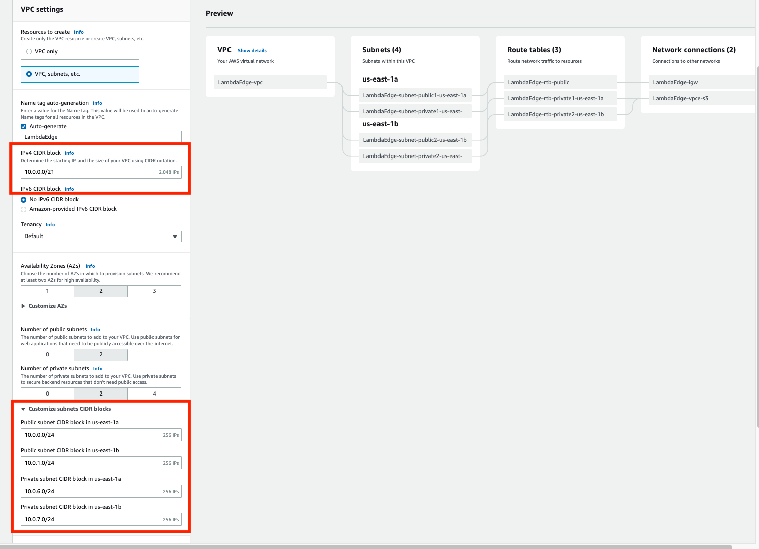
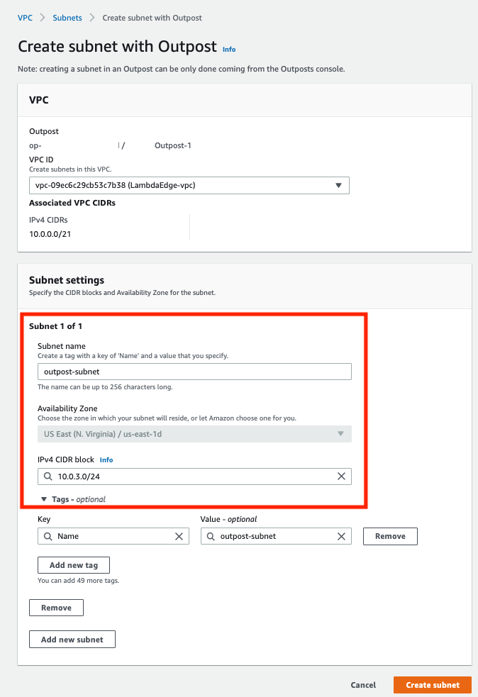
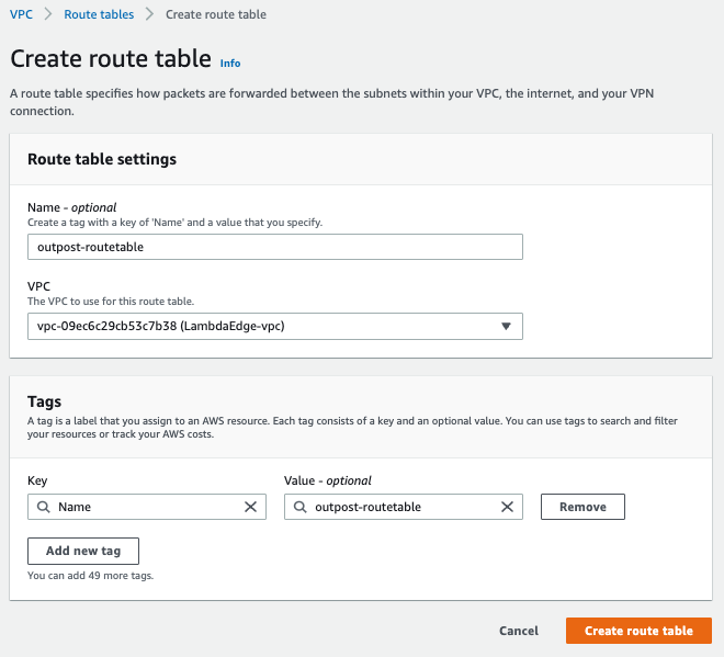
Creating your EIC Endpoint

Only one endpoint is required per VPC. To create or modify an endpoint and connect to a resource, a user must have the required IAM permissions, and any security groups associated with your VPC resources must have a rule to allow connectivity. Refer to the following resources for more details on configuring security groups and sample IAM permissions.

The AWS CLI or Console can be used to create an EIC Endpoint, and we demonstrate the AWS CLI in the following. To create an EIC Endpoint using the Console, refer to the documentation.

Creating an EIC Endpoint with the AWS CLI

To create an EIC Endpoint with the AWS CLI, run the following command, replacing [SUBNET] with your subnet ID and [SG-ID] with your security group ID:

aws ec2 create-instance-connect-endpoint \
    --subnet-id [SUBNET] \
    --security-group-id [SG-ID]

After creating an EIC Endpoint using the AWS CLI or Console, and granting the user IAM permission to create a tunnel, a connection can be established. Now we discuss how to connect to Linux instances using SSH. However, note that you can also use the OpenTunnel API to connect to instances via RDP.

Connecting to your Linux Instance using SSH

With your EIC Endpoint set up in your VPC subnet, you can connect using SSH. Traditionally, access to an EC2 instance using SSH was controlled by key pairs and network access controls. With EIC Endpoint, an additional layer of control is enabled through IAM policy, leading to an enhanced security posture for remote access. We describe two methods to connect via SSH in the following.

One-click command

To further reduce the operational burden of creating and rotating SSH keys, you can use the new ec2-instance-connect ssh command from the AWS CLI. With this new command, we generate ephemeral keys for you to connect to your instance. Note that this command requires use of the OpenSSH client. To use this command and connect, you need IAM permissions as detailed here.

Once configured, you can connect using the new AWS CLI command, shown in the following figure:
Figure 3 shows the AWS CLI view if successfully connecting to your instance using the one-click command. When running the command, you are prompted to connect and can access your instance.

Figure 3. AWS CLI view upon successful SSH connection to your instance

To test connecting to your instance from the AWS CLI, you can run the following command where [INSTANCE] is the instance ID of your EC2 instance:

aws ec2-instance-connect ssh --instance-id [INSTANCE]

Note that you can still use long-lived SSH credentials to connect if you must maintain existing workflows, which we will show in the following. However, note that dynamic, frequently rotated credentials are generally safer.

Open-tunnel command

You can also connect using SSH with standard tooling or using the proxy command. To establish a private tunnel (TCP proxy) to the instance, you must run one AWS CLI command, which you can see in the following figure:

Figure 4 shows the AWS CLI view after running the aws ec2-instance-connect open-tunnel command and connecting to your instance.Figure 4. AWS CLI view after running new SSH open-tunnel command, creating a private tunnel to connect to our EC2 instance

You can run the following command to test connectivity, where [INSTANCE] is the instance ID of your EC2 instance and [SSH-KEY] is the location and name of your SSH key. For guidance on the use of SSH keys, refer to our documentation on Amazon EC2 key pairs and Linux instances.

ssh ec2-user@[INSTANCE] \
    -i [SSH-KEY] \
    -o ProxyCommand='aws ec2-instance-connect open-tunnel \
    --instance-id %h'

Once we have our EIC Endpoint configured, we can SSH into our EC2 instances without a public IP or IGW using the AWS CLI.

Conclusion

EIC Endpoint provides a secure solution to connect to your instances via SSH or RDP in private subnets without IGWs, public IPs, agents, and bastion hosts. By configuring an EIC Endpoint for your VPC, you can securely connect using your existing client tools or the Console/AWS CLI. To learn more, visit the EIC Endpoint documentation.

Building Sustainable, Efficient, and Cost-Optimized Applications on AWS

Post Syndicated from Sheila Busser original https://aws.amazon.com/blogs/compute/building-sustainable-efficient-and-cost-optimized-applications-on-aws/

This blog post is written by Isha Dua Sr. Solutions Architect AWS, Ananth Kommuri Solutions Architect AWS, and Dr. Sam Mokhtari Sr. Sustainability Lead SA WA for AWS.

Today, more than ever, sustainability and cost-savings are top of mind for nearly every organization. Research has shown that AWS’ infrastructure is 3.6 times more energy efficient than the median of U.S. enterprise data centers and up to five times more energy efficient than the average in Europe. That said, simply migrating to AWS isn’t enough to meet the Environmental, Social, Governance (ESG) and Cloud Financial Management (CFM) goals that today’s customers are setting. In order to make conscious use of our planet’s resources, applications running on the cloud must be built with efficiency in mind.

That’s because cloud sustainability is a shared responsibility. At AWS, we’re responsible for optimizing the sustainability of the cloud – building efficient infrastructure, enough options to meet every customer’s needs, and the tools to manage it all effectively. As an AWS customer, you’re responsible for sustainability in the cloud – building workloads in a way that minimizes the total number of resource requirements and makes the most of what must be consumed.

Most AWS service charges are correlated with hardware usage, so reducing resource consumption also has the added benefit of reducing costs. In this blog post, we’ll highlight best practices for running efficient compute environments on AWS that maximize utilization and decrease waste, with both sustainability and cost-savings in mind.

First: Measure What Matters

Application optimization is a continuous process, but it has to start somewhere. The AWS Well Architected Framework Sustainability pillar includes an improvement process that helps customers map their journey and understand the impact of possible changes. There is a saying “you can’t improve what you don’t measure.”, which is why it’s important to define and regularly track metrics which are important to your business. Scope 2 Carbon emissions, such as those provided by the AWS Customer Carbon Footprint Tool, are one metric that many organizations use to benchmark their sustainability initiatives, but they shouldn’t be the only one.

Even after AWS meets our 2025 goal of powering our operations with 100% renewable energy, it’s still be important to maximize the utilization and minimize the consumption of the resources that you use. Just like installing solar panels on your house, it’s important to limit your total consumption to ensure you can be powered by that energy. That’s why many organizations use proxy metrics such as vCPU Hours, storage usage, and data transfer to evaluate their hardware consumption and measure improvements made to infrastructure over time.

In addition to these metrics, it’s helpful to baseline utilization against the value delivered to your end-users and customers. Tracking utilization alongside business metrics (orders shipped, page views, total API calls, etc) allows you to normalize resource consumption with the value delivered to your organization. It also provides a simple way to track progress towards your goals over time. For example, if the number of orders on your ecommerce site remained constant over the last month, but your AWS infrastructure usage decreased by 20%, you can attribute the efficiency gains to your optimization efforts, not changes in your customer behavior.

Utilize all of the available pricing models

Compute tasks are the foundation of many customers’ workloads, so it typically sees biggest benefit by optimization. Amazon EC2 provides resizable compute across a wide variety of compute instances, is well-suited to virtually every use case, is available via a number of highly flexible pricing options. One of the simplest changes you can make to decrease your costs on AWS is to review the purchase options for the compute and storage resources that you already use.

Amazon EC2 provides multiple purchasing options to enable you to optimize your costs based on your needs. Because every workload has different requirements, we recommend a combination of purchase options tailored for your specific workload needs. For steady-state workloads that can have a 1-3 year commitment, using Compute Savings Plans helps you save costs, move from one instance type to a newer, more energy-efficient alternative, or even between compute solutions (e.g., from EC2 instances to AWS Lambda functions, or AWS Fargate).

EC2 Spot instances are another great way to decrease cost and increase efficiency on AWS. Spot Instances make unused Amazon EC2 capacity available for customers at discounted prices. At AWS, one of our goals it to maximize utilization of our physical resources. By choosing EC2 Spot instances, you’re running on hardware that would otherwise be sitting idle in our datacenters. This increases the overall efficiency of the cloud, because more of our physical infrastructure is being used for meaningful work. Spot instances use market-based pricing that changes automatically based on supply and demand. This means that the hardware with the most spare capacity sees the highest discounts, sometimes up to XX% off on-demand prices, to encourage our customers to choose that configuration.

Savings Plans are ideal for predicable, steady-state work. On-demand is best suited for new, stateful, and spiky workloads which can’t be instance, location, or time flexible. Finally, Spot instances are a great way to supplement the other options for applications that are fault tolerant and flexible. AWS recommends using a mix of pricing models based on your workload needs and ability to be flexible.

By using these pricing models, you’re creating signals for your future compute needs, which helps AWS better forecast resource demands, manage capacity, and run our infrastructure in a more sustainable way.

Choose efficient, purpose-built processors whenever possible

Choosing the right processor for your application is as equally important consideration because under certain use cases a more powerful processor can allow for the same level of compute power with a smaller carbon footprint. AWS has the broadest choice of processors, such as Intel – Xeon scalable processors, AMD – AMD EPYC processors, GPU’s FPGAs, and Custom ASICs for Accelerated Computing.

AWS Graviton3, AWS’s latest and most power-efficient processor, delivers 3X better CPU performance per-watt than any other processor in AWS, provides up to 40% better price performance over comparable current generation x86-based instances for various workloads, and helps customers reduce their carbon footprint. Consider transitioning your workload to Graviton-based instances to improve the performance efficiency of your workload (see AWS Graviton Fast Start and AWS Graviton2 for ISVs). Note the considerations when transitioning workloads to AWS Graviton-based Amazon EC2 instances.

For machine learning (ML) workloads, use Amazon EC2 instances based on purpose-built Amazon Machine Learning (Amazon ML) chips, such as AWS TrainiumAWS Inferentia, and Amazon EC2 DL1.

Optimize for hardware utilization

The goal of efficient environments is to use only as many resources as required in order to meet your needs. Thankfully, this is made easier on the cloud because of the variety of instance choices, the ability to scale dynamically, and the wide array of tools to help track and optimize your cloud usage. At AWS, we offer a number of tools and services that can help you to optimize both the size of individual resources, as well as scale the total number of resources based on traffic and load.

Two of the most important tools to measure and track utilization are Amazon CloudWatch and the AWS Cost & Usage Report (CUR). With CloudWatch, you can get a unified view of your resource metrics and usage, then analyze the impact of user load on capacity utilization over time. The Cost & Usage Report (CUR) can help you understand which resources are contributing the most to your AWS usage, allowing you to fine-tune your efficiency and save on costs. CUR data is stored in S3, which allows you to query it with tools like Amazon Athena or generate custom reports in Amazon QuickSight or integrate with AWS Partner tools for better visibility and insights.

An example of a tool powered by CUR data is the AWS Cost Intelligence Dashboard. The Cost Intelligence Dashboard provides a detailed, granular, and recommendation-driven view of your AWS usage. With its prebuilt visualizations, it can help you identify which service and underlying resources are contributing the most towards your AWS usage, and see the potential savings you can realize by optimizing. It even provides right sizing recommendations and the appropriate EC2 instance family to help you optimize your resources.

Cost Intelligence Dashboard is also integrated with AWS Compute Optimizer, which makes instance type and size recommendations based on workload characteristics. For example, it can identify if the workload is CPU-intensive, if it exhibits a daily pattern, or if local storage is accessed frequently. Compute Optimizer then infers how the workload would have performed on various hardware platforms (for example, Amazon EC2 instance types) or using different configurations (for example, Amazon EBS volume IOPS settings, and AWS Lambda function memory sizes) to offer recommendations. For stable workloads, check AWS Compute Optimizer at regular intervals to identify right-sizing opportunities for instances. By right sizing with Compute Optimizer, you can increase resource utilization and reduce costs by up to 25%. Similarly, Lambda Power Tuning can help choose the memory allocated to Lambda functions is an optimization process that balances speed (duration) and cost while lowering your carbon emission in the process.

CloudWatch metrics are used to power EC2 Autoscaling, which can automatically choose the right instance to fit your needs with attribute-based instance selection and scale your entire instance fleet up and down based on demand in order to maintain high utilization. AWS Auto Scaling makes scaling simple with recommendations that let you optimize performance, costs, or balance between them. Configuring and testing workload elasticity will help save money, maintain performance benchmarks, and reduce the environmental impact of workloads. You can utilize the elasticity of the cloud to automatically increase the capacity during user load spikes, and then scale down when the load decreases. Amazon EC2 Auto Scaling allows your workload to automatically scale up and down based on demand. You can set up scheduled or dynamic scaling policies based on metrics such as average CPU utilization or average network in or out. Then, you can integrate AWS Instance Scheduler and Scheduled scaling for Amazon EC2 Auto Scaling to schedule shut downs and terminate resources that run only during business hours or on weekdays to further reduce your carbon footprint.

Design applications to minimize overhead and use fewer resources

Using the latest Amazon Machine Image (AMI) gives you updated operating systems, packages, libraries, and applications, which enable easier adoption as more efficient technologies become available. Up-to-date software includes features to measure the impact of your workload more accurately, as vendors deliver features to meet their own sustainability goals.

By reducing the amount of equipment that your company has on-premises and using managed services, you can help facilitate the move to a smaller, greener footprint. Instead of buying, storing, maintaining, disposing of, and replacing expensive equipment, businesses can purchase services as they need that are already optimized with a greener footprint. Managed services also shift responsibility for maintaining high average utilization and sustainability optimization of the deployed hardware to AWS. Using managed services will help distribute the sustainability impact of the service across all of the service tenants, thereby reducing your individual contribution. The following services help reduce your environmental impact because capacity management is automatically optimized.

 AWS  Managed Service   Recommendation for sustainability improvement

Amazon Aurora

You can use Amazon  Aurora Serverless to automatically start up, shut down, and scale capacity up or down based on your application’s needs.

Amazon Redshift

You can use Amazon Redshift Serverless to run and scale data warehouse capacity.

AWS Lambda

You can Migrate AWS Lambda functions to Arm-based AWS Graviton2 processors.

Amazon ECS

You can run Amazon ECS on AWS Fargate to avoid the undifferentiated heavy lifting by leveraging sustainability best practices AWS put in place for management of the control plane.

Amazon EMR

You can use EMR Serverless to avoid over- or under-provisioning resources for your data processing jobs.

AWS Glue

You can use Auto-scaling for AWS Glue to enable on-demand scaling up and scaling down of the computing resources.

 Centralized data centers consume a lot of energy, produce a lot of carbon emissions and cause significant electronic waste. While more data centers are moving towards green energy, an even more sustainable approach (alongside these so-called “green data centers”) is to actually cut unnecessary cloud traffic, central computation and storage as much as possible by shifting computation to the edge. Edge Computing stores and uses data locally, on or near the device it was created on. This reduces the amount of traffic sent to the cloud and, at scale, can limit the overall energy used and carbon emissions.

Use storage that best supports how your data is accessed and stored to minimize the resources provisioned while supporting your workload. Solid state devices (SSDs) are more energy intensive than magnetic drives and should be used only for active data use cases. You should look into using ephemeral storage whenever possible and categorize, centralize, deduplicate, and compress persistent storage.

AWS OutpostsAWS Local Zones and AWS Wavelength services deliver data processing, analysis, and storage close to your endpoints, allowing you to deploy APIs and tools to locations outside AWS data centers. Build high-performance applications that can process and store data close to where it’s generated, enabling ultra-low latency, intelligent, and real-time responsiveness. By processing data closer to the source, edge computing can reduce latency, which means that less energy is required to keep devices and applications running smoothly. Edge computing can help to reduce the carbon footprint of data centers by using renewable energy sources such as solar and wind power.

Conclusion

In this blog post, we discussed key methods and recommended actions you can take to optimize your AWS compute infrastructure for resource efficiency. Using the appropriate EC2 instance types with the right size, processor, instance storage and pricing model can enhance the sustainability of your applications. Use of AWS managed services, options for edge computing and continuously optimizing your resource usage can further improve the energy efficiency of your workloads. You can also analyze the changes in your emissions over time as you migrate workloads to AWS, re-architect applications, or deprecate unused resources using the Customer Carbon Footprint Tool.

Ready to get started? Check out the AWS Sustainability page to find out more about our commitment to sustainability and learn more about renewable energy usage, case studies on sustainability through the cloud, and more.

Running AI-ML Object Detection Model to Process Confidential Data using Nitro Enclaves

Post Syndicated from Sheila Busser original https://aws.amazon.com/blogs/compute/running-ai-ml-object-detection-model-to-process-confidential-data-using-nitro-enclaves/

This blog post was written by, Antoine Awad, Solutions Architect, Kevin Taylor, Senior Solutions Architect and Joel Desaulniers, Senior Solutions Architect.

Machine Learning (ML) models are used for inferencing of highly sensitive data in many industries such as government, healthcare, financial, and pharmaceutical. These industries require tools and services that protect their data in transit, at rest, and isolate data while in use. During processing, threats may originate from the technology stack such as the operating system or programs installed on the host which we need to protect against. Having a process that enforces the separation of roles and responsibilities within an organization minimizes the ability of personnel to access sensitive data. In this post, we walk you through how to run ML inference inside AWS Nitro Enclaves to illustrate how your sensitive data is protected during processing.

We are using a Nitro Enclave to run ML inference on sensitive data which helps reduce the attack surface area when the data is decrypted for processing. Nitro Enclaves enable you to create isolated compute environments within Amazon EC2 instances to protect and securely process highly sensitive data. Enclaves have no persistent storage, no interactive access, and no external networking. Communication between your instance and your enclave is done using a secure local channel called a vsock. By default, even an admin or root user on the parent instance will not be able to access the enclave.

Overview

Our example use-case demonstrates how to deploy an AI/ML workload and run inferencing inside Nitro Enclaves to securely process sensitive data. We use an image to demonstrate the process of how data can be encrypted, stored, transferred, decrypted and processed when necessary, to minimize the risk to your sensitive data. The workload uses an open-source AI/ML model to detect objects in an image, representing the sensitive data, and returns a summary of the type of objects detected. The image below is used for illustration purposes to provide clarity on the inference that occurs inside the Nitro Enclave. It was generated by adding bounding boxes to the original image based on the coordinates returned by the AI/ML model.

Image of airplanes with bounding boxes

Figure 1 – Image of airplanes with bounding boxes

To encrypt this image, we are using a Python script (Encryptor app – see Figure 2) which runs on an EC2 instance, in a real-world scenario this step would be performed in a secure environment like a Nitro Enclave or a secured workstation before transferring the encrypted data. The Encryptor app uses AWS KMS envelope encryption with a symmetrical Customer Master Key (CMK) to encrypt the data.

Image Encryption with AWS KMS using Envelope Encryption

Figure 2 – Image Encryption with AWS KMS using Envelope Encryption

Note, it’s also possible to use asymmetrical keys to perform the encryption/decryption.

Now that the image is encrypted, let’s look at each component and its role in the solution architecture, see Figure 3 below for reference.

  1. The Client app reads the encrypted image file and sends it to the Server app over the vsock (secure local communication channel).
  2. The Server app, running inside a Nitro Enclave, extracts the encrypted data key and sends it to AWS KMS for decryption. Once the data key is decrypted, the Server app uses it to decrypt the image and run inference on it to detect the objects in the image. Once the inference is complete, the results are returned to the Client app without exposing the original image or sensitive data.
  3. To allow the Nitro Enclave to communicate with AWS KMS, we use the KMS Enclave Tool which uses the vsock to connect to AWS KMS and decrypt the encrypted key.
  4. The vsock-proxy (packaged with the Nitro CLI) routes incoming traffic from the KMS Tool to AWS KMS provided that the AWS KMS endpoint is included on the vsock-proxy allowlist. The response from AWS KMS is then sent back to the KMS Enclave Tool over the vsock.

As part of the request to AWS KMS, the KMS Enclave Tool extracts and sends a signed attestation document to AWS KMS containing the enclave’s measurements to prove its identity. AWS KMS will validate the attestation document before decrypting the data key. Once validated, the data key is decrypted and securely returned to the KMS Tool which securely transfers it to the Server app to decrypt the image.

Solution architecture diagram for this blog post

Figure 3 – Solution architecture diagram for this blog post

Environment Setup

Prerequisites

Before we get started, you will need the following prequisites to deploy the solution:

  1. AWS account
  2. AWS Identity and Access Management (IAM) role with appropriate access

AWS CloudFormation Template

We are going to use AWS CloudFormation to provision our infrastructure.

  1. Download the CloudFormation (CFN) template nitro-enclave-demo.yaml. This template orchestrates an EC2 instance with the required networking components such as a VPC, Subnet and NAT Gateway.
  2. Log in to the AWS Management Console and select the AWS Region where you’d like to deploy this stack. In the example, we select Canada (Central).
  3. Open the AWS CloudFormation console at: https://console.aws.amazon.com/cloudformation/
  4. Choose Create Stack, Template is ready, Upload a template file. Choose File to select nitro-enclave-demo.yaml that you saved locally.
  5. Choose Next, enter a stack name such as NitroEnclaveStack, choose Next.
  6. On the subsequent screens, leave the defaults, and continue to select Next until you arrive at the Review step
  7. At the Review step, scroll to the bottom and place a checkmark in “I acknowledge that AWS CloudFormation might create IAM resources with custom names.” and click “Create stack”
  8. The stack status is initially CREATE_IN_PROGRESS. It will take around 5 minutes to complete. Click the Refresh button periodically to refresh the status. Upon completion, the status changes to CREATE_COMPLETE.
  9. Once completed, click on “Resources” tab and search for “NitroEnclaveInstance”, click on its “Physical ID” to navigate to the EC2 instance
  10. On the Amazon EC2 page, select the instance and click “Connect”
  11. Choose “Session Manager” and click “Connect”

EC2 Instance Configuration

Now that the EC2 instance has been provisioned and you are connected to it, follow these steps to configure it:

  1. Install the Nitro Enclaves CLI which will allow you to build and run a Nitro Enclave application:
    sudo amazon-linux-extras install aws-nitro-enclaves-cli -y
    sudo yum install aws-nitro-enclaves-cli-devel -y
    
  2. Verify that the Nitro Enclaves CLI was installed successfully by running the following command:
    nitro-cli --version

    Nitro Enclaves CLI

  3. To download the application from GitHub and build a docker image, you need to first install Docker and Git by executing the following commands:
    sudo yum install git -y
    sudo usermod -aG ne ssm-user
    sudo usermod -aG docker ssm-user
    sudo systemctl start docker && sudo systemctl enable docker
    

Nitro Enclave Configuration

A Nitro Enclave is an isolated environment which runs within the EC2 instance, hence we need to specify the resources (CPU & Memory) that the Nitro Enclaves allocator service dedicates to the enclave.

  1. Enter the following commands to set the CPU and Memory available for the Nitro Enclave allocator service to allocate to your enclave container:
    ALLOCATOR_YAML=/etc/nitro_enclaves/allocator.yaml
    MEM_KEY=memory_mib
    DEFAULT_MEM=20480
    sudo sed -r "s/^(\s*${MEM_KEY}\s*:\s*).*/\1${DEFAULT_MEM}/" -i "${ALLOCATOR_YAML}"
    sudo systemctl start nitro-enclaves-allocator.service && sudo systemctl enable nitro-enclaves-allocator.service
    
  2. To verify the configuration has been applied, run the following command and note the values for memory_mib and cpu_count:
    cat /etc/nitro_enclaves/allocator.yaml

    Enclave Configuration File

Creating a Nitro Enclave Image

Download the Project and Build the Enclave Base Image

Now that the EC2 instance is configured, download the workload code and build the enclave base Docker image. This image contains the Nitro Enclaves Software Development Kit (SDK) which allows an enclave to request a cryptographically signed attestation document from the Nitro Hypervisor. The attestation document includes unique measurements (SHA384 hashes) that are used to prove the enclave’s identity to services such as AWS KMS.

  1. Clone the Github Project
    cd ~/ && git clone https://github.com/aws-samples/aws-nitro-enclaves-ai-ml-object-detection.git
  2. Navigate to the cloned project’s folder and build the “enclave_base” image:
    cd ~/aws-nitro-enclaves-ai-ml-object-detection/enclave-base-image
    sudo docker build ./ -t enclave_base

    Note: The above step will take approximately 8-10 minutes to complete.

Build and Run The Nitro Enclave Image

To build the Nitro Enclave image of the workload, build a docker image of your application and then use the Nitro CLI to build the Nitro Enclave image:

  1. Download TensorFlow pre-trained model:
    cd ~/aws-nitro-enclaves-ai-ml-object-detection/src
    mkdir -p models/faster_rcnn_openimages_v4_inception_resnet_v2_1 && cd models/
    wget -O tensorflow-model.tar.gz https://tfhub.dev/google/faster_rcnn/openimages_v4/inception_resnet_v2/1?tf-hub-format=compressed
    tar -xvf tensorflow-model.tar.gz -C faster_rcnn_openimages_v4_inception_resnet_v2_1
  2. Navigate to the use-case folder and build the docker image for the application:
    cd ~/aws-nitro-enclaves-ai-ml-object-detection/src
    sudo docker build ./ -t nitro-enclave-container-ai-ml:latest
  3. Use the Nitro CLI to build an Enclave Image File (.eif) using the docker image you built in the previous step:
    sudo nitro-cli build-enclave --docker-uri nitro-enclave-container-ai-ml:latest --output-file nitro-enclave-container-ai-ml.eif
  4. The output of the previous step produces the Platform configuration registers or PCR hashes and a nitro enclave image file (.eif). Take note of the PCR0 value, which is a hash of the enclave image file.Example PCR0:
    {
        "Measurements": {
            "PCR0": "7968aee86dc343ace7d35fa1a504f955ee4e53f0d7ad23310e7df535a187364a0e6218b135a8c2f8fe205d39d9321923"
            ...
        }
    }
  5. Launch the Nitro Enclave container using the Enclave Image File (.eif) generated in the previous step and allocate resources to it. You should allocate at least 4 times the EIF file size for enclave memory. This is necessary because the tmpfs filesystem uses half of the memory and the remainder of the memory is used to uncompress the initial initramfs where the application executable resides. For CPU allocation, you should allocate CPU in full cores i.e. 2x vCPU for x86 hyper-threaded instances.
    In our case, we are going to allocate 14GB or 14,366 MB for the enclave:

    sudo nitro-cli run-enclave --cpu-count 2 --memory 14336 --eif-path nitro-enclave-container-ai-ml.eif

    Note: Allow a few seconds for the server to boot up prior to running the Client app in the below section “Object Detection using Nitro Enclaves”.

Update the KMS Key Policy to Include the PCR0 Hash

Now that you have the PCR0 value for your enclave image, update the KMS key policy to only allow your Nitro Enclave container access to the KMS key.

  1. Navigate to AWS KMS in your AWS Console and make sure you are in the same region where your CloudFormation template was deployed
  2. Select “Customer managed keys”
  3. Search for a key with alias “EnclaveKMSKey” and click on it
  4. Click “Edit” on the “Key Policy”
  5. Scroll to the bottom of the key policy and replace the value of “EXAMPLETOBEUPDATED” for the “kms:RecipientAttestation:PCR0” key with the PCR0 hash you noted in the previous section and click “Save changes”

AI/ML Object Detection using a Nitro Enclave

Now that you have an enclave image file, run the components of the solution.

Requirements Installation for Client App

  1. Install the python requirements using the following command:
    cd ~/aws-nitro-enclaves-ai-ml-object-detection/src
    pip3 install -r requirements.txt
  2. Set the region that your CloudFormation stack is deployed in. In our case we selected Canada (Centra)
    CFN_REGION=ca-central-1
  3. Run the following command to encrypt the image using the AWS KMS key “EnclaveKMSKey”, make sure to replace “ca-central-1” with the region where you deployed your CloudFormation template:
    python3 ./envelope-encryption/encryptor.py --filePath ./images/air-show.jpg --cmkId alias/EnclaveKMSkey --region $CFN_REGION
  4. Verify that the output contains: file encrypted? True
    Note: The previous command generates two files: an encrypted image file and an encrypted data key file. The data key file is generated so we can demonstrate an attempt from the parent instance at decrypting the data key.

Launching VSock Proxy

Launch the VSock Proxy which proxies requests from the Nitro Enclave to an external endpoint, in this case, to AWS KMS. Note the file vsock-proxy-config.yaml contains a list of endpoints which allow-lists the endpoints that an enclave can communicate with.

cd ~/aws-nitro-enclaves-ai-ml-object-detection/src
vsock-proxy 8001 "kms.$CFN_REGION.amazonaws.com" 443 --config vsock-proxy-config.yaml &

Object Detection using Nitro Enclaves

Send the encrypted image to the enclave to decrypt the image and use the AI/ML model to detect objects and return a summary of the objects detected:

cd ~/aws-nitro-enclaves-ai-ml-object-detection/src
python3 client.py --filePath ./images/air-show.jpg.encrypted | jq -C '.'

The previous step takes around a minute to complete when first called. Inside the enclave, the server application decrypts the image, runs it through the AI/ML model to generate a list of objects detected and returns that list to the client application.

Parent Instance Credentials

Attempt to Decrypt Data Key using Parent Instance Credentials

To prove that the parent instance is not able to decrypt the content, attempt to decrypt the image using the parent’s credentials:

cd ~/aws-nitro-enclaves-ai-ml-object-detection/src
aws kms decrypt --ciphertext-blob fileb://images/air-show.jpg.data_key.encrypted --region $CFN_REGION

Note: The command is expected to fail with AccessDeniedException, since the parent instance is not allowed to decrypt the data key.

Cleaning up

  1. Open the AWS CloudFormation console at: https://console.aws.amazon.com/cloudformation/.
  2. Select the stack you created earlier, such as NitroEnclaveStack.
  3. Choose Delete, then choose Delete Stack.
  4. The stack status is initially DELETE_IN_PROGRESS. Click the Refresh button periodically to refresh its status. The status changes to DELETE_COMPLETE after it’s finished and the stack name no longer appears in your list of active stacks.

Conclusion

In this post, we showcase how to process sensitive data with Nitro Enclaves using an AI/ML model deployed on Amazon EC2, as well as how to integrate an enclave with AWS KMS to restrict access to an AWS KMS CMK so that only the Nitro Enclave is allowed to use the key and decrypt the image.

We encrypt the sample data with envelope encryption to illustrate how to protect, transfer and securely process highly sensitive data. This process would be similar for any kind of sensitive information such as personally identifiable information (PII), healthcare or intellectual property (IP) which could also be the AI/ML model.

Dig deeper by exploring how to further restrict your AWS KMS CMK using additional PCR hashes such as PCR1 (hash of the Linux kernel and bootstrap), PCR2 (Hash of the application), and other hashes available to you.

Also, try our comprehensive Nitro Enclave workshop which includes use-cases at different complexity levels.

Running AWS Lambda functions on AWS Outposts using AWS IoT Greengrass

Post Syndicated from Sheila Busser original https://aws.amazon.com/blogs/compute/running-aws-lambda-functions-on-aws-outposts-using-aws-iot-greengrass/

This blog post is written by Adam Imeson, Sr. Hybrid Edge Specialist Solution Architect.

Today, AWS customers can deploy serverless applications in AWS Regions using a variety of AWS services. Customers can also use AWS Outposts to deploy fully managed AWS infrastructure at virtually any datacenter, colocation space, or on-premises facility.

AWS Outposts extends the cloud by bringing AWS services to customers’ premises to support their hybrid and edge workloads. This post will describe how to deploy Lambda functions on an Outpost using AWS IoT Greengrass.

Consider a customer who has built an application that runs in an AWS Region and depends on AWS Lambda. This customer has a business need to enter a new geographic market, but the nearest AWS Region is not close enough to meet application latency or data residency requirements. AWS Outposts can help this customer extend AWS infrastructure and services to their desired geographic region. This blog post will explain how a customer can move their Lambda-dependent application to an Outpost.

Overview

In this walkthrough you will create a Lambda function that can run on AWS IoT Greengrass and deploy it on an Outpost. This architecture results in an AWS-native Lambda function running on the Outpost.

Architecture overview - Lambda functions on AWS Outposts

Deploying Lambda functions on Outposts rack

Prerequisites: Building a VPC

To get started, build a VPC in the same Region as your Outpost. You can do this with the create VPC option in the AWS console. The workflow allows you to set up a VPC with public and private subnets, an internet gateway, and NAT gateways as necessary. Do not consume all of the available IP space in the VPC with your subnets in this step, because you will still need to create Outposts subnets after this.

Now, build a subnet on your Outpost. You can do this by selecting your Outpost in the Outposts console and choosing Create Subnet in the drop-down Actions menu in the top right.

Confirm subnet details

Choose the VPC you just created and select a CIDR range for your new subnet that doesn’t overlap with the other subnets that are already in the VPC. Once you’ve created the subnet, you need to create a new subnet route table and associate it with your new subnet. Go into the subnet route tables section of the VPC console and create a new route table. Associate the route table with your new subnet. Add a 0.0.0.0/0 route pointing at your VPC’s internet gateway. This sets the subnet up as a public subnet, which for the purposes of this post will make it easier to access the instance you are about to build for Greengrass Core. Depending on your requirements, it may make more sense to set up a private subnet on your Outpost instead. You can also add a route pointing at your Outpost’s local gateway here. Although you won’t be using the local gateway during this walkthrough, adding a route to the local gateway makes it possible to trigger your Outpost-hosted Lambda function with on-premises traffic.

Create a new route table

Associate the route table with the new subnet

Add a 0.0.0.0/0 route pointing at your VPC’s internet gateway

Setup: Launching an instance to run Greengrass Core

Create a new EC2 instance in your Outpost subnet. As long as your Outpost has capacity for your desired instance type, this operation will proceed the same way as any other EC2 instance launch. You can check your Outpost’s capacity in the Outposts console or in Amazon CloudWatch:

I used a c5.large instance running Amazon Linux 2 with 20 GiB of Amazon EBS storage for this walkthough. You can pick a different instance size or a different operating system in accordance with your application’s needs and the AWS IoT Greengrass documentation. For the purposes of this tutorial, we assign a public IP address to the EC2 instance on creation.

Step 1: Installing the AWS IoT Greengrass Core software

Once your EC2 instance is up and running, you will need to install the AWS IoT Greengrass Core software on the instance. Follow the AWS IoT Greengrass documentation to do this. You will need to do the following:

  1. Ensure that your EC2 instance has appropriate AWS permissions to make AWS API calls. You can do this by attaching an instance profile to the instance, or by providing AWS credentials directly to the instance as environment variables, as in the Greengrass documentation.
  2. Log in to your instance.
  3. Install OpenJDK 11. For Amazon Linux 2, you can use sudo amazon-linux-extras install java-openjdk11 to do this.
  4. Create the default system user and group that runs components on the device, with
    sudo useradd —system —create-home ggc_user
    sudo groupadd —system ggc_group
  5. Edit the /etc/sudoers file with sudo visudosuch that the entry for the root user looks like root ALL=(ALL:ALL) ALL
  6. Enable cgroups and enable and mount the memory and devices cgroups. In Amazon Linux 2, you can do this with the grubby utility as follows:
    sudo grubby --args="cgroup_enable=memory cgroup_memory=1 systemd.unified_cgroup_hierarchy=0" --update-kernel /boot/vmlinuz-$(uname -r)
  7. Type sudo reboot to reboot your instance with the cgroup boot parameters enabled.
  8. Log back in to your instance once it has rebooted.
  9. Use this command to download the AWS IoT Greengrass Core software to the instance:
    curl -s https://d2s8p88vqu9w66.cloudfront.net/releases/greengrass-nucleus-latest.zip > greengrass-nucleus-latest.zip
  10. Unzip the AWS IoT Greengrass Core software:
    unzip greengrass-nucleus-latest.zip -d GreengrassInstaller && rm greengrass-nucleus-latest.zip
  11. Run the following command to launch the installer. Replace each argument with appropriate values for your particular deployment, particularly the aws-region and thing-name arguments.
    sudo -E java -Droot="/greengrass/v2" -Dlog.store=FILE \
    -jar ./GreengrassInstaller/lib/Greengrass.jar \
    --aws-region region \
    --thing-name MyGreengrassCore \
    --thing-group-name MyGreengrassCoreGroup \
    --thing-policy-name GreengrassV2IoTThingPolicy \
    --tes-role-name GreengrassV2TokenExchangeRole \
    --tes-role-alias-name GreengrassCoreTokenExchangeRoleAlias \
    --component-default-user ggc_user:ggc_group \
    --provision true \
    --setup-system-service true \
    --deploy-dev-tools true
  12. You have now installed the AWS IoT Greengrass Core software on your EC2 instance. If you type sudo systemctl status greengrass.service then you should see output similar to this:

Step 2: Building and deploying a Lambda function

Now build a Lambda function and deploy it to the new Greengrass Core instance. You can find example local Lambda functions in the aws-greengrass-lambda-functions GitHub repository. This example will use the Hello World Python 3 function from that repo.

  1. Create the Lambda function. Go to the Lambda console, choose Create function, and select the Python 3.8 runtime:

  1. Choose Create function at the bottom of the page. Once your new function has been created, copy the code from the Hello World Python 3 example into your function:

  1. Choose Deploy to deploy your new function’s code.
  2. In the top right, choose Actions and select Publish new version. For this particular function, you would need to create a deployment package with the AWS IoT Greengrass SDK for the function to work on the device. I’ve omitted this step for brevity as it is not a main focus of this post. Please reference the Lambda documentation on deployment packages and the Python-specific deployment package docs if you want to pursue this option.

  1. Go to the AWS IoT Greengrass console and choose Components in the left-side pop-in menu.
  2. On the Components page, choose Create component, and then Import Lambda function. If you prefer to do this programmatically, see the relevant AWS IoT Greengrass documentation or AWS CloudFormation documentation.
  3. Choose your new Lambda function from the drop-down.

Create component

  1. Scroll to the bottom and choose Create component.
  2. Go to the Core devices menu in the left-side nav bar and select your Greengrass Core device. This is the Greengrass Core EC2 instance you set up earlier. Make a note of the core device’s name.

  1. Use the left-side nav bar to go to the Deployments menu. Choose Create to create a new deployment, which will place your Lambda function on your Outpost-hosted core device.
  2. Give the deployment a name and select Core device, providing the name of your core device. Choose Next.

  1. Select your Lambda function and choose Next.

  1. Choose Next again, on both the Configure components and Configure advanced settings On the last page, choose Deploy.

You should see a green message at the top of the screen indicating that your configuration is now being deployed.

Clean up

  1. Delete the Lambda function you created.
  2. Terminate the Greengrass Core EC2 instance.
  3. Delete the VPC.

Conclusion

Many customers use AWS Outposts to expand applications into new geographies. Some customers want to run Lambda-based applications on Outposts. This blog post shows how to use AWS IoT Greengrass to build Lambda functions which run locally on Outposts.

To learn more about Outposts, please contact your AWS representative and visit the Outposts homepage and documentation.

Amazon EC2 DL1 instances Deep Dive

Post Syndicated from Sheila Busser original https://aws.amazon.com/blogs/compute/amazon-ec2-dl1-instances-deep-dive/

This post is written by Amr Ragab, Principal Solutions Architect, Amazon EC2.

AWS is excited to announce that the new Amazon Elastic Compute Cloud (Amazon EC2) DL1 instances are now generally available in US-East (N. Virginia) and US-West (Oregon). DL1 provides up to 40% better price performance for training deep learning models as compared to current generation GPU-based EC2 instances. The dl1.24xlarge instance type features eight Intel-Habana Gaudi accelerators, which are custom-built to train deep learning models. Each Gaudi accelerator has 32 GB of high bandwidth memory (HBM2) and a peer-to-peer bidirectional bandwidth of 100 Gbps RoCE, for a total bidirectional interconnect bandwidth of 700 Gbps per card. Further instance specifications are as follows:

Instance Size vCPU Instance Memory (GiB) Gaudi Accelerators Network Bandwidth (Gbps) Total Accelerator Interconnect (Gbs) Local Instance Storage EBS Bandwidth (Gbps)
d1.24xlarge 96 768 8 4×100 Gbps 700 4x1TB NVMe 19

Instance Architecture

System architecture of the amazon ec2 dl1 instances.

As the preceding instance architecture indicates, pairs of Gaudi accelerators (e.g., Gaudi0 and Gaudi1) are attached directly through a PCIe Gen3x16 link. Additionally, peer-to-peer networking via 100 Gbps RoCEv2 links – with seven active links per card – provides a torus configuration with a total of 700 Gbps of interconnect bandwidth per card. This topology is a separate interconnect outside of the two NUMA domains. Furthermore, the instance supports four EFA ENIs and 4x1TB of local NVMe SSD storage. We will provide a peer-direct driver over EFA, which will let you utilize high throughput, low latency peer-direct networking between accelerators across multiple instances to efficiently scale multi-node distributed training workloads.

Quick Start

Quickly get started with DL1 and SynapseAI SDK through with the following options:

1) Habana Deep Learning AMIs provided by AWS.

2) AWS Marketplace AMIs provided by Habana.

3) Using Packer to build a custom Amazon Machine Images (AMI) provided by this GitHub repo. This repo also provides build scripts to create Amazon Elastic Container Service (Amazon ECS) and Amazon Elastic Kubernetes Service (Amazon EKS) AMIs.

After selecting an AMI, launch a dl1.24xlarge instance in either us-east-1 or us-west-2. To help identify in which availability zone(s) dl1.24xlarge is available, run the following command:

aws ec2 describe-instance-type-offerings \
--location-type availability-zone \
--filters Name=instance-type,Values=dl1.24xlarge \
--region us-west-2 \
--output table

Once launched, you can connect to the instance over SSH (with the correct security group attached).

Habana Collectives Communication Library (HCL/HCCL)

As part of the Habana SynapseAI SDK, Habana Gaudi’s use the HCCL library for handling the collectives between HPUs. Get more information on HCCL here. On DL1 through the HCL-tests, we can confirm close to 700 Gbps (689 Gbps) per card for the collectives tested as follows.

You can confirm these tests by cloning the github repo here.

Habana DL1 HCCL tests.

Amazon EKS Quick Start

Support for DL1 on Amazon EKS is available today with Amazon EKS versions > 1.19. The following is a quick start to get up and running quickly with DL1.

The following dependencies will be needed:

eksctl – You need version 0.70.0+ of eksctl.
kubectl – You use Kubernetes version 1.20 in this post.

Create EKS cluster:

eksctl create cluster --region us-east-1 --without-nodegroup \
--vpc-public-subnets subnet-037d8e430963c2d3e,subnet-0abe898359a7d43e9

Nodegroup configuration – save the following codeblock to a file called dl1-managed-ng.yaml. Replace the AMI ID in the code block with the AMI created earlier.

apiVersion: eksctl.io/v1alpha5
kind: ClusterConfig

metadata:
  name: fabulous-rainbow-1635807811
  region: us-west-2

vpc:
  id: vpc-34f1894c
  subnets:
    public:
      endpoint-one:
        id: subnet-4532e73d
      endpoint-two:
        id: subnet-8f8b7dc5

managedNodeGroups:
  - name: dl1-ng-1d
    instanceType: dl1.24xlarge
    volumeSize: 200
    instancePrefix: dl1-ng-1d-worker
    ami: ami-072c632cbbc2255b3
    iam:
      withAddonPolicies:
        imageBuilder: true
        autoScaler: true
        ebs: true
        fsx: true
        cloudWatch: true
    ssh:
      allow: true
      publicKeyName: amrragab-aws
    subnets:
    - endpoint-one
    minSize: 1
    desiredCapacity: 1
    maxSize: 4
    overrideBootstrapCommand: |
      #!/bin/bash
      /etc/eks/bootstrap.sh fabulous-rainbow-1635807811

Create the managed nodegroup with the following command:

eksctl create nodegroup -f dl1-managed-ng.yaml

Once the nodegroup has been completed, you must apply the habana-k8s-device-plugin

kubectl create -f https://vault.habana.ai/artifactory/docker-k8s-device-plugin/habana-k8s-device-plugin.yaml

Once completed, you should see the Gaudi devices as an allocatable resource in your EKS
cluster, presenting 8 Gaudi accelerators per DL1 node in the cluster.

Allocatable:

attachable-volumes-aws-ebs: 39
cpu:                        95690m
ephemeral-storage:          192188443124
habana.ai/gaudi:            8
hugepages-1Gi:              0
hugepages-2Mi:              30000Mi
memory:                     753055132Ki
pods:                       15

Example Distributed Machine Learning (ML) Workloads

The following tables are examples of Mixed Precision/FP32 training results comparing DL1 to the common GPU instances used for ML training.

Model: ResNet50
Framework: TensorFlow 2
Dataset: Imagenet2012
GitHub: https://github.com/HabanaAI/Model-
References/tree/master/TensorFlow/computer_vision/Resnets/resnet_keras

Instance Type Batch Size
Mixed Precision Training Throughput (images/sec)
8x Gaudi – 32 GB (dl1.24xlarge) 256 13036
8x A100 – 40 GB (p4d.24xlarge) 256 17921
8x V100 – 32 GB (p3dn.24xlarge) 256 9685
8x V100 – 16GB (p3.16xlarge) 256 8945

Model: Bert Large – Pretraining
Framework: Pytorch 1.9
Dataset: Wikipedia/BooksCorpus
GitHub: https://github.com/HabanaAI/Model-References/tree/master/PyTorch/nlp/bert

Instance Type Batch Size
@128 Sequence
Length
Mixed Precision Training Throughput (seq/sec)
8x Gaudi – 32 GB (dl1.24xlarge) 256 1318
8x A100 – 40 GB (p4d.24xlarge) 8192 2979
8x V100 – 32 GB (p3dn.24xlarge) 8192 1458
8x V100 – 16GB (p3.16xlarge) 8192 1013

You can find a more comprehensive list of ML models supported with performance data here. Support for containers with TensorFlow and Pytorch are also available. Furthermore, you can stay up-to-date with the operator support for TensorFlow and Pytorch.

CONCLUSION

We are excited to innovate on behalf of our customers and provide a diverse choice in ML accelerators with DL1 instances. The DL1 instances powered by Gaudi accelerators can provide up to 40% better price performance for training deep learning models as compared to current generation GPU-based EC2 instances. DL1 instances use the Habana SynapseAI SDK with framework support in Pytorch and TensorFlow. Additional future support for EFA with peer direct HPUs across nodes will also be supported. Now it’s time to go power up your ML workloads with Amazon EC2 DL1 instances.