All posts by Talia Nassi

Benefits of migrating to event-driven architecture

Post Syndicated from Talia Nassi original https://aws.amazon.com/blogs/compute/benefits-of-migrating-to-event-driven-architecture/

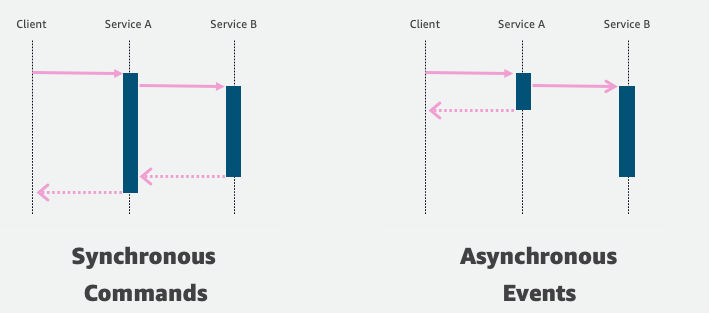
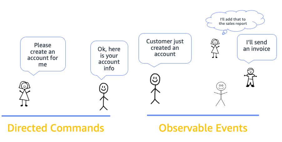
Two common options when building applications are request-response and event-driven architecture. In request-response architecture, an application’s components communicate via API calls. The client sends a request and expects a response before performing the next task. In event-driven architecture, the client generates an event and can immediately move on to its next task. Different parts of the application then respond to the event as needed.

events

In this post, you learn about reasons to consider moving from request-response architecture to an event-driven architecture.

Challenges with request-response architecture

When starting to a build a new application, many developers default to a request-response architecture. A request-response architecture may tightly integrate components and those components communicate via synchronous calls. While a request-response approach is often easier to get started with, it can become challenging as your application grows in complexity.

In this post, I review an example request-response ecommerce application and demonstrate the challenges of tightly coupled integrations. Then I show you how building the same application with an event-driven architecture can give you increased scalability, fault tolerance, and developer velocity.

Close coordination between microservices

In a typical ecommerce application that uses a synchronous API, the client makes a request to place an order and the order service sends the request downstream to an invoice service. If successful, the order service responds with a success message or confirmation number.

In this initial stage, this is a straightforward connection between the two services. The challenge comes when you add more services that integrate with the order service.

picture

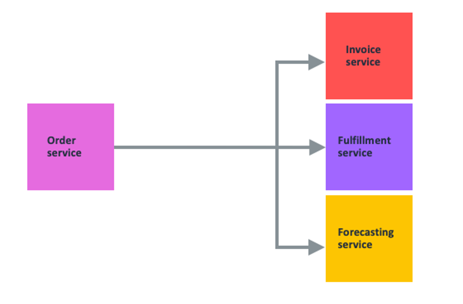
If you add a fulfillment service and a forecasting service, the order service has more responsibilities and more complexity. The order service must know how to call each service’s API, from the API call structure to the API’s retry semantics. If there are any backwards incompatible changes to the APIs, the order service team must update them. The system forwards heavy traffic spikes to the order service’s dependency, which may not have the same scaling capabilities. Also, dependent services may transmit errors back up the stack to the client.

Error handling and retries

Now, you add new downstream services for fulfillment and shipping orders to the ecommerce application.

architecture

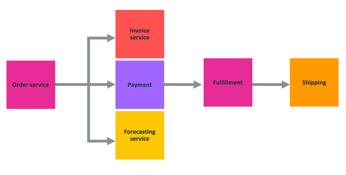
In the happy path, everything works as expected: The order service triggers invoicing, payment systems, and updates forecasting. Once payment clears, this triggers the fulfillment and packing of the order, and then informs the shipping service to request tracking information.

However, if the fulfillment center cannot find the product because they are out of stock, then fulfillment might have to alert the invoice service, then reverse the payment or issue a refund. If fulfillment fails, then the system that triggers shipping might fail as well. Forecasting must also be updated to reflect the change. This remediation workflow is all just to address one of the many potential “unhappy paths” that can occur in this API-driven ecommerce application.

Close coordination between development teams

In a synchronously integrated application, teams must coordinate any new services that are added to the application. This can slow down each development team’s ability to release new features. Imagine your team works on the payment service but you weren’t told that another team added a new rewards service. What now happens when the fulfillment service errors?

Fulfillment may orchestrate all the other services. Your payments team gets a message and you undo the payment, but you may not know who handles retries and error logic. If the rewards service changes vendors and has a new API, and does not tell your team, you may not be aware of the new service.

Ultimately, it can be hard to coordinate these orchestrations and workflows as systems become more complex and management adds more services. This is one reason that it can be beneficial to migrate to event-driven architecture.

Benefits of event-driven architecture

Event-driven architecture can help solve the problems of the close coordination of microservices, error handling and retries, and coordination between development teams.

Close coordination between microservices

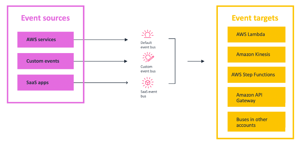
In event-driven architecture, the publisher emits an event, which is acknowledged by the event bus. The event bus routes events to subscribers, which process events with self-contained business logic. There is no direct communication between publishers and subscribers.

Decoupled applications enable teams to act more independently, which can increase their velocity. For example, with an API-based integration, if your team wants to know about a change that happened in another team’s microservice, you might have to ask that team to make an API call to your service. Consequently, you may have to account for authentication, coordination with the other team over the structure of the API call. This causes back and forth between teams, which slows down development time. With an event-driven application, you can subscribe to events sent from your microservice and the event bus (for example, Amazon EventBridge) takes care of routing the event and handling authentication.

Error handling and retries

Another reason to migrate to event-driven architecture is to handle unpredictable traffic. Ecommerce websites like Amazon.com have variable amounts of traffic depending on the day. Once you place an order, several things happen.

First, Amazon checks your credit card to make sure that funds are available. Then, Amazon has to pack the merchandise and load onto trucks. That all happens in an Amazon fulfillment center. There is no synchronous API call for the Amazon backend to package and ship products. After the system confirms your payment, the front end puts together some information describing the event and puts your account number, credit card info, and what you bought in a packaged event and put it into the cloud and onto a queue. Later, another piece of software removes the event from the queue and starts the packaging and shipping.

The key point about this process is that these processes can all run at different rates. Normally, the rate at which customers place orders and the rate at which the warehouses can get the boxes packed are roughly equivalent. However, on busy days like Prime Day, customers place orders much more quickly than the warehouses can operate.

Ecommerce applications, like Amazon.com, must be able to scale up to handle unpredictable traffic. When a customer places an order, an event bus like Amazon EventBridge receives the event and all of the downstream microservices are able to select the order event for processing. Because each of the microservices can fail independently, there are no single points of failure.

Loose coordination between development teams

Event-driven architectures promote development team independence due to loose coupling between publishers and subscribers. Applications can subscribe to events with routing requirements and business logic that are separate from the publisher and other subscribers. This allows publishers and subscribers to change independently of each other, providing more flexibility to the overall architecture.

Decoupled applications also allow you to build new features faster. Adding new features or extending existing ones can be simpler with event-driven architectures because you either add new events, or modify existing ones. This process removes complexity in your application.

Conclusion

In this post, you learn about the challenges of developing applications with request-response architecture. In request-response architecture, the client must send a request and wait for a response before moving on to its next task. As applications grow in complexity, this tightly coupled architecture can cause issues. Event-driven architectures can increase scalability, fault tolerance, and developer velocity by decoupling components of your application.

For more serverless content, go to serverlessland.com.

Working with events and the Amazon EventBridge schema registry

Post Syndicated from Talia Nassi original https://aws.amazon.com/blogs/compute/working-with-events-and-amazon-eventbridge-schema-registry/

Event-driven architecture, at its core, is driven by producers creating events and subscribers being made aware of those events and acting upon them. An event is a data representation of something that happened elsewhere in the application or from an outside producer. When building event-driven applications, it is critical to determine what events exist in the application, who produces them, and who subscribes and react to them.

The first step in identifying these events is to work through the process of event discovery. In this process, you decide the events that the event source produces, and what parts of the application must know about those events. Events schemas describe the structure of an event and fields included in the event. If the event’s contents match the event target’s requirements, the service sends the event to the target. If you have an existing application that you want to discover event schemas automatically for you, can enable EventBridge schema discovery. If you are building a new application, you can conduct an event discovery exercise.

An event bus connects the event to the subscriber. The event bus at AWS is Amazon EventBridge. Use EventBridge to choreograph interactions between event sources and event targets.

In this post, you learn how to perform an event discovery exercise with your team. It shows how to create a schema registry with EventBridge, and how to represent the event as an object in your code to use in your application.

Event discovery

In the event discovery phase, all business stakeholders of an application come together and write down all the possible events that can happen. For example, possible events for an ecommerce application include: Account Created, Item added to cart, Order Placed. Write events in Noun + Past Tense Verb format.

Events
Account Created
Item Added
Order Placed

Notice that events are not technical or focused on implementation; rather they are real-world things that happened in your system. This is because everyone, from developers to product owners, must understand them. In the event discovery phase, events act as your business requirements. Later, developers then translate those requirements into code.

Once you have the events laid out, you decide who is interested in each event. For example, consider the events listed for the ecommerce application: Account Created, Item Added to cart, and Order Placed.

Events Subscribers
Account Created

Marketing team

Security team

Item Added Inventory team
Order Placed Fulfillment team

Whenever a user creates an account, the marketing team subscribes to that event to send the account holder promotions. The security team encrypts the account holder’s user name and password into a database to save the account credentials. Whenever a user places an order, the system sends an email notification with the order details to stakeholders. The system also sends a message to the fulfillment team to start packing and shipping the order. This approach decouples the interactions between all of these services. This decoupling is beneficial because it increases developer independence by reducing the dependencies on other teams to write integrations.

Once the initial event schema planning is complete, you want to ensure that developers can continue to build new features without needing to coordinate with other teams closely on event schemas. For this reason, \EventBridge’s schema registry and automated schema discovery can help developers quickly build new features based on their application’s events.

You use EventBridge schema registries to search for, find, and track different schemas generated by your application. You can also automatically find schemas with the automated schema registry.

EventBridge schema registry and discovery

Applications can have many different types of events. Events generated from AWS services, third-party SaaS applications, and your custom applications.

With so many event sources, it can be challenging to know what to expect when consuming events. A schema represents the structure of an event. It describes what happened in the event, where the event came from, and the timestamp. The event schema is important for developers as it shows what data contained in the event, and allows them to write code based on that data.

For example, an Order Placed event might always contain a list of items in the order as an array, and a user ID as an integer. EventBridge helps automate the manual process of finding and documenting schemas. There are two capabilities to highlight: Schema registry and schema discovery.

A schema registry is a repository that stores a collection of schemas. You can use a schema registry to search for, find, and track different schemas used and generated by your application. AWS automatically stores schemas for all AWS sources for EventBridge in your schema registry. SaaS partner and custom schemas can be generated and added to the registry using the schema discovery feature. A schema registry enables you to use events as objects in your code more easily.

Adding an event to the EventBridge schema registry

In this tutorial, you create an Account Created event, which includes a user’s name and email address.

  1. Navigate to the Amazon EventBridge console and choose Schemas from the left panel.step 1There are three types of schemas represented in the tabs: AWS event schema registry, discovered schema registry, and custom schema registry.When you choose AWS event schema registry, you can search for any AWS service or event that is supported by EventBridge. There, you can view the schema for that event.
    pic 2

  2. To create a custom schema registry for your application, navigate to the custom schema registry tab and choose Create registry.
  3. Enter a name for the registry and then choose Create.
  4. There are currently no schemas in the registry. Choose Create custom schema to create one.
  5. Choose your registry as the destination and call the schema “user”. You can choose to load the schema template using an OpenAPI format from the Load Template option. You can then manually enter data for each of the fields.
  6. Alternatively, you can have the service discover the schema from JSON. Remember that events are written in JSON. Choose the Discover from JSON tab and enter the following code:{"id": 1, "name": "Talia Nassi", "emailAddress": "[email protected]"}
  7. Choose Discover schema.
  8. EventBridge extrapolates the schema from this information. The schema shows that the ID is a number, the name is a string, and the email address is a string. Choose Create to create the schema.
  9. When you choose your schema from the schema registry, you can see the structure of the event you just created.

Representing events as objects in your code with code bindings

Once a schema is added to the registry, you can download a code binding, which allows you to represent the event as an object in your code. You can take advantage of IDE features such as validation and auto-complete. Code bindings are available for Java, Python, or TypeScript programming languages. You can download bindings from the Amazon EventBridge Console, or directly from your IDE with the AWS Toolkit plugin for IntelliJ and Visual Studio Code.

Choose the programming language you prefer, then choose Download. This downloads the code binding to your local machine.

You can also choose to download code bindings directly to your IDE with the AWS Toolkit. This tutorial uses VS Code but you can also use IntelliJ.

  1. Ensure you have VS Code installed.
  2. Navigate to the VS Code marketplace and search for AWS and install the AWS Toolkit. You may have to restart VS Code.
  3. Choose a profile to connect to AWS. Set the Region to the same Region that you created the schema in. You see this icon on the left panel when you access the AWS Explorer:
  4. Choose Schemas from the left panel, then choose your schema, myRegistry. Open user by right clicking and choosing View Schema.
  5. You can now use this event object in your code.

Conclusion

In this post, you learn about event discovery, schema registry, and schema discovery. Event discovery is essential when creating event-driven applications because it allows the team to see which events are created by your application, and who needs to subscribe to those events.

Events have specific structures, called schemas. Your schema registry includes all of the schemas for your events. You can use the schema registry to search for events produced by other teams, which can make development faster. You learn how to create a custom schema registry, and how to download code bindings to use events in your code.

For more information, visit Serverless Land.

Building an event-driven application with Amazon EventBridge

Post Syndicated from Talia Nassi original https://aws.amazon.com/blogs/compute/building-an-event-driven-application-with-amazon-eventbridge/

In event-driven architecture, services interact with each other through events. An event is something that happened in your application (for example, an item was put into a cart, a new order was placed). Events are JSON objects that tell you information about something that happened in your application. In event-driven architecture, each component of the application raises an event whenever anything changes. Other components listen and decide what to do with it and how they would like to react.

When you build applications with event-driven architecture, you decouple your event sources and event targets. This can enable teams to act more independently, because your services are loosely coupled. When you add new features to your applications, you raise new events and then decide on the event source and event target. The event source is what emits the event, and the event target is what subscribes to or receives the event. Decoupling event sources and event targets can greatly speed up development time, and it can simplify making changes to your application.

Decoupling your application can allow for more seamless cross-team collaboration. For example, let’s say you are a developer at an ecommerce company and you are building a serverless ecommerce application. Your team is in charge of the account creation and authentication process. You build the login workflow, and raise an event when a new user creates an account.

When the event is raised, other teams can be alerted. The marketing team can listen for the Account Created event and act on it (for example, send promotional emails). In this decoupled architecture, event producers and consumers don’t have to know about each other. They only have to listen to events and act accordingly when they are interested in an event. This can speed up development by reducing the complexity caused by building new features.

In AWS, events are choreographed through Amazon EventBridge rules. A rule matches incoming events from an event source and sends them to event targets for processing.

eventbridge architecture

EventBridge accepts events from many different event sources, including over 200 AWS services, custom events from your Lambda functions or applications, and third-party SaaS applications. You specify an action to take when EventBridge receives an event that matches the event pattern in the rule. When an event matches, Amazon EventBridge sends the event to the specified target and triggers the action defined in the rule.

To route events from these sources to the correct target, the events must be placed on a corresponding event bus. There are three types of event buses. The first type is the default bus, which is always available in every account, and it’s where AWS events are routed to. The second type is a custom event bus. You can create custom event buses for your own applications to meet your business needs. Lastly, you can also create SaaS event buses, which are created when you configure SaaS applications as an event source.

There are many potential event targets. Event targets are what the event bus route to once a corresponding event happens. Targets include AWS Lambda, Amazon Kinesis, AWS Step Functions, Amazon API Gateway, and even event buses in other accounts. This flexible design allows you to create a wide variety of integration patterns based on your specific needs.

Configuring events with Amazon EventBridge

This tutorial sends an event from Amazon S3 (the event source) to AWS Lambda (the event target) using an event rule.

In this tutorial, you learn how to configure events with Amazon EventBridge by deploying an AWS Serverless Application Model template. The AWS Serverless Application Model (AWS SAM) is an open-source framework for building serverless applications. It provides shorthand syntax to express functions, APIs, databases, and event source mappings. AWS SAM is an extension of AWS CloudFormation, which is the AWS infrastructure as code tool. You define resources using CloudFormation in your AWS SAM template and use the full suite of resources, intrinsic functions, and other template features that are available in AWS CloudFormation.

First, you upload images to an S3 bucket. This raises an event, which invokes a Lambda function, which resizes the image and places it in a different S3 bucket.

Prerequisites:

  1. AWS SAM CLI (If you use AWS Cloud9, this is installed for you)

To configure events with Amazon EventBridge:

  1. Navigate to the Serverlessland Patterns Collection and choose the pattern Amazon S3 to Amazon EventBridge to AWS Lambda. This AWS SAM template deploys an S3 bucket, a Lambda function, an EventBridge rule, and the IAM resources required to run the application.
  2. Copy and paste the cloning instructions in your terminal.
  3. Run sam deploy --guided to deploy the pattern.
  4. You see the success message:
  5. Navigate to the EventBridge console and choose Rules from the left panel. Then choose the rule that was created by AWS SAM (starting with sam-app)
    The event source is S3 and the rule is invoked when an image is put into the source bucket in S3. Next, notice that the event target is the Lambda function that you created from the AWS SAM template.
  6. Navigate to the S3 console and choose Buckets on the left panel. Then choose the bucket that was created for you (starting with sam-app). Choose the Properties tab, and note that the integration with EventBridge is on.
  7. From the Objects tab, choose Upload, and upload an image.

  8. Navigate to the Lambda console and choose your Lambda function (starting with sam-app). Select the Monitor tab, and choose View Logs in CloudWatch.
  9. You can see the event that triggered the Lambda function in the logs:

Adding more event rules to your application

In the previous example, you add an EventBridge rule that routes events from S3 (the event source) to Lambda (the event target) using an event bus. Now, add another rule:

  1. From the EventBridge console, choose Rules, and then choose Create rule.
  2. Enter a name and description for the rule.
  3. Define the event pattern that is used to invoke the event targets. For Service provider, choose AWS, and for Service name choose S3. For Event type, choose Amazon S3 event notification, and in the event dropdown choose Object created. You are configuring the event source to be an object created in your S3 bucket.
  4. Select either the default AWS event bus or a custom event bus.
  5. Select the event target. In this example, configure an Amazon CloudWatch log group. Enter any name for the log group, which is created automatically.
  6. Choose Create.
  7. Upload an image to the S3 bucket, as shown in step 7 above.
  8. Navigate to the Amazon CloudWatch console and choose Log groups from the left panel. Choose the log group, and then choose a log stream.
  9. The event is logged to CloudWatch Logs.

Adding a second event rule did not change the event source’s behavior or affect other event targets.

Conclusion

This post is a brief introduction of event-driven architecture, and walks through a tutorial where you create an event-driven application with the Serverlessland Patterns Collection. You also add two different event rules to your event bus.

For more serverless learning resources, visit Serverless Land.

Getting Started with Event-Driven Architecture

Post Syndicated from Talia Nassi original https://aws.amazon.com/blogs/compute/getting-started-with-event-driven-architecture/

In modern application development, event-driven architecture is becoming more prominent because it can make building applications in the cloud easier. Event-driven architecture can allow you to decouple your services, which increases developer velocity, and can make it easier for you to debug applications. It also can help remove the bottleneck that occurs when features expand across different teams, which allows teams to progress more independently.

One way to think about how an application works is as a system that reacts to events from other places, like from within your application. In this approach, you focus on the system’s interaction with its surroundings as a transmission of events. The application receives and creates events. Inputs to the application and outputs from the application act as events. At its core, this is event-driven architecture.

API-driven architecture vs. event-driven architecture

Commands/APIs Events
Synchronous Asynchronous

Has an intent

Directed to a target

It’s a fact

Happened in the past

“CreateAccount”

“AddProduct”

“AccountCreated”

“ProductAdded”

A common way of making components of an application work together is through an API-driven, request-response architecture where you have requests and responses. For example, you query a list of orders from an Orders API, and the Orders API responds with a list of orders. This is an example of synchronous architecture. The system asking for the orders waits for the response. You cannot move on until the response comes back. In this approach, you send commands that are directed to a target (for example, “place this order” or “add this record to the database”).

sync vs async

In a synchronous model, the client makes a request to Service A. Service A calls Service B, but then Service A waits for Service B to respond before it continues on and eventually responds to the client.

In asynchronous, event-driven architecture, there is no response path. The service surfaces the event and then immediately moves forward. The trade-off here is that there’s no direct channel for Service B to pass back information to Service A, besides confirming it received the event. But in many cases, you don’t need that explicit coupling between the request and response channels.

An event is something that happened. For example, a new account is created, or an item is dropped into an Amazon S3 bucket. Events are immutable, which means you cannot change them. Once an event happens, you cannot undo it. For example, if there is an event raised when an order is placed, there can be another event for an order being cancelled. Events can come from various places such as messaging systems or databases.

Events are JSON objects that tell you information about something that happened in your application. In event-driven architecture, events represent facts. Each component of the application raises an event whenever anything changes. Other components listen and decide what to do with it and how they would like to react.

event

In the event above, S3 raises the event when you put the image into an Amazon S3 bucket. The event source is an S3 bucket named sam-app-sourcebucket. The object that is put into the bucket is called “brad.jpeg”.

Request-driven applications typically use directed commands to coordinate downstream functions to complete an activity and are often tightly coupled. This makes it harder to determine when errors occur in your application. Event-driven applications create events that are observable by other services and systems. However, the event producer is unaware of which consumers, if any, are listening. Typically, these are loosely coupled.

Events are observable. Any service that is authorized can watch an event. Consider a coffee shop example where there is a barista, who makes coffee, and a pastry chef, who makes pastries. When a customer enters the coffee shop and orders a cup of coffee, the barista starts to make the coffee, and the pastry chef takes no action.

However, if a customer comes in to the coffee shop and orders a chocolate croissant, then the pastry chef starts making the chocolate croissant, and the barista takes no action. The pastry chef is only interested in orders relating to pastries and the barista is only interested in events relating to coffee.

In an ecommerce application, like Amazon.com, there are different departments that respond to different events. You can place orders through Whole Foods, Amazon Fresh, and Amazon.com. When you place an order with Amazon Fresh, the subscribers to that event take action and fulfill your order.

event

Event-driven architecture and command-driven architecture also differ in the ways that they store state. In a typical command-driven architecture, you have only one component store a particular piece of data, and other components ask that component for the data when needed.

In event-driven architecture, every component stores all the data it needs and listens to update events for that data. In command-driven architecture, the component that stores the data is responsible for updating it. In event-driven architecture, all it has to do is ensure new events are raised on the updates.

Benefits of using event-driven architecture

Decoupling event sources and event targets

Many applications are built in a monolith, where the components are tightly coupled, and are highly dependent on each other. This proves to be problematic when there are bugs and you are trying to pinpoint exactly what part of the application is failing. Decoupled architectures are composed of components or services that are loosely coupled. In an event-driven, decoupled architecture, you broadcast events without caring who responds to them. This saves time because events can be queued and forwarded whenever the receiver is ready to process them. This allows for building scalable, highly modifiable systems.

Decoupled applications enable teams to act more independently, which increases their velocity. For example, with an API-based integration, if my team wants to know about some change that happened in another team’s microservice, I have to ask that team to make an API call to my service. That means I have to deal with authentication, coordination with the other team over the structure of the API call, etc. This causes back and forth between teams, which slows down development time. With an event-driven application, you can subscribe to events sent from a microservice and the event router (for example, Amazon EventBridge) takes care of routing the event and handling authentication.

Decoupled applications also allow you to build new features faster. Adding new features or extending existing ones is simpler with event-driven architectures. This is because you only have to choose the event you need to trigger your new feature, and subscribe to it. There’s no need to modify any of your existing services to add new functionality.

Write less code

When you build applications using event-driven architecture, often you write less code because you only need to consider new events, as well as which service is subscribed to those events. For example, if you are building new features for your application, all you have to do is consider the existing events and then add senders and receivers as necessary. In this way, you speed up development time because each functional unit is smaller and there is often less code.

Better extensibility

In the example above, you built a highly extensible application. Other teams can extend features and add functionality without impacting other microservices. By publishing events using EventBridge, this application integrates with existing systems, but also enables any future application to integrate as an event consumer. Producers of events have no knowledge of event consumers, which can help simplify the microservice logic.

Enhancing team collaboration

A common process to build applications is to work with your product managers and business stakeholders to gather requirements. Developers then translate those requirements into code. However, there may be a disconnect between the product requirements and the code. When you use events, everyone in the business understands the logic. You define the events in an application (for example, a customer adds an item to their shopping cart or a customer account is created) and that becomes your product requirements. Whenever that action happens, it produces an event, and whoever is interested can take action on that event.

For example, a marketing manager could be interested whenever a customer creates a new account. One way to choreograph this in event-driven architecture is to have a Marketing event bus that listens for the New Account event. There could also be other teams that are interested, such as the Analytics team, who also subscribe to that event. Each team/service can subscribe to events that are relevant to them. Event-driven architecture is a great way for businesses to describe their business problems and represent them.

Conclusion

This post introduces events, and then compares event-driven architecture to command-driven, request-response architecture. It also explains the benefits of event-driven architecture, including decoupling event sources and targets, writing less code, having better extensibility, and enhancing team collaboration.

For more serverless learning resources, visit Serverless Land.

Publishing messages in batch to Amazon SNS topics

Post Syndicated from Talia Nassi original https://aws.amazon.com/blogs/compute/publishing-messages-in-batch-to-amazon-sns-topics/

This post is written by Heeki Park (Principal Solutions Architect, Serverless Specialist), Marc Pinaud (Senior Product Manager, Amazon SNS), Amir Eldesoky (Software Development Engineer, Amazon SNS), Jack Li (Software Development Engineer, Amazon SNS), and William Nguyen (Software Development Engineer, Amazon SNS).

Today, we are announcing the ability for AWS customers to publish messages in batch to Amazon SNS topics. Until now, you were only able to publish one message to an SNS topic per Publish API request. With the new PublishBatch API, you can send up to 10 messages at a time in a single API request. This reduces cost for API requests by up to 90%, as you need fewer API requests to publish the same number of messages.

Introducing the PublishBatch API

Consider a log processing application where you process system logs and have different requirements for downstream processing. For example, you may want to do inference on
incoming log data, populate an operational Amazon OpenSearch Service environment, and store log data in an enterprise data lake.

Systems send log data to a standard SNS topic, and Amazon SQS queues and Amazon Kinesis Data Firehose are configured as subscribers. An AWS Lambda function subscribes to the first SQS queue and uses machine learning models to perform inference to detect security incidents or system access anomalies. A Lambda function subscribes to the second SQS queue and emits those log entries to an Amazon OpenSearch Service cluster. The workload uses Kibana dashboards to visualize log data. An Amazon Kinesis Data Firehose delivery stream subscribes to the SNS topic and archives all log data into Amazon S3. This allows data scientists to conduct further investigation and research on those logs.

To do this, the following Java code publishes a set of log messages. In this code, you construct a publish request for a single message to an SNS topic and submit that request via the publish() method:

// tab 1: standard publish example
private static AmazonSNS snsClient;
private static final String MESSAGE_PAYLOAD = " 192.168.1.100 - - [28/Oct/2021:10:27:10 -0500] "GET /index.html HTTP/1.1" 200 3395";

PublishRequest request = new PublishRequest()
    .withTopicArn(topicArn)
    .withMessage(MESSAGE_PAYLOAD);
PublishResult response = snsClient.publish(request);

// tab 2: fifo publish example
private static AmazonSNS snsClient;
private static final String MESSAGE_PAYLOAD = " 192.168.1.100 - - [28/Oct/2021:10:27:10 -0500] "GET /index.html HTTP/1.1" 200 3395";
private static final String MESSAGE_FIFO_GROUP = "server1234";

PublishRequest request = new PublishRequest()
    .withTopicArn(topicArn)
    .withMessage(MESSAGE_PAYLOAD)
    .withMessageGroupId(MESSAGE_FIFO_GROUP)
    .withMessageDeduplicationId(UUID.randomUUID().toString());
PublishResult response = snsClient.publish(request);

If you extended the example above and had 10 log lines that each needed to be published as a message, you would have to write code to construct 10 publish requests, and subsequently submit each of those requests via the publish() method.

With the new ability to publish batch messages, you write the following new code. In the code below, you construct a list of publish entries first, then create a single publish batch request, and subsequently submit that batch request via the new publishBatch() method. In the code below, you use a sample helper method getLoggingPayload(i) to get the appropriate payload for the message, which you can replace with your own business logic.

// tab 1: standard publish example
private static final String MESSAGE_BATCH_ID_PREFIX = "server1234-batch-id-";

List<PublishBatchRequestEntry> entries = IntStream.range(0, 10)
.mapToObj(i -> {
new PublishBatchRequestEntry()
.withId(MESSAGE_BATCH_ID_PREFIX + i)
.withMessage(getLoggingPayload(i));
})
.collect(Collectors.toList());
PublishBatchRequest request = new PublishBatchRequest()
.withTopicArn(topicArn)
.withPublishBatchRequestEntries(entries);
PublishBatchResult response = snsClient.publishBatch(request);

// tab 2: fifo publish example
private static final String MESSAGE_BATCH_ID_PREFIX = "server1234-batch-id-";
private static final String MESSAGE_FIFO_GROUP = "server1234";


List<PublishBatchRequestEntry> entries = IntStream.range(0, 10)
.mapToObj(i -> {
new PublishBatchRequestEntry()
.withId(MESSAGE_BATCH_ID_PREFIX + i)
.withMessage(getLoggingPayload(i))
.withMessageGroupId(MESSAGE_FIFO_GROUP)
.withMessageDeduplicationId(UUID.randomUUID().toString());
})
.collect(Collectors.toList());
PublishBatchRequest request = new PublishBatchRequest()
.withTopicArn(topicArn)
.withPublishBatchRequestEntries(entries);
PublishBatchResult response = snsClient.publishBatch(request);

In the list of publish requests, the application must assign a unique batch ID (up to 80 characters) to each publish request within that batch. When the SNS service successfully receives a message, the SNS service assigns a unique message ID and returns that message ID in the response object.

If publishing to a FIFO topic, the SNS service additionally returns a sequence number in the response. When publishing a batch of messages, the PublishBatchResult object returns a list of response objects for successful and failed messages. If you iterate through the list of response objects for successful messages, you might see the following:

// tab 1: standard publish output
{
"Id": "server1234-batch-id-0",
"MessageId": "fcaef5b3-e9e3-5c9e-b761-ac46c4a779bb",
...
}

// tab 2: fifo publish output
{
"Id": "server1234-batch-id-0",
"MessageId": "fcaef5b3-e9e3-5c9e-b761-ac46c4a779bb",
"SequenceNumber": "10000000000000003000",
...
}

When receiving the message from SNS in the SQS queue, the application reads the following message:

// tab 1: standard publish output
{
"Type" : "Notification",
"MessageId" : "fcaef5b3-e9e3-5c9e-b761-ac46c4a779bb",
"TopicArn" : "arn:aws:sns:us-east-1:112233445566:publishBatchTopic",
"Message" : "payload-0",
"Timestamp" : "2021-10-28T22:58:12.862Z",
"UnsubscribeURL" : "http://sns.us-east-1.amazon.com/?Action=Unsubscribe&SubscriptionArn=arn:aws:sns:us-east-1:112233445566:publishBatchTopic:ff78260a-0953-4b60-9c2c-122ebcb5fc96"
}

// tab 2: fifo publish output
{
"Type" : "Notification",
"MessageId" : "fcaef5b3-e9e3-5c9e-b761-ac46c4a779bb",
"SequenceNumber" : "10000000000000003000",
"TopicArn" : "arn:aws:sns:us-east-1:112233445566:publishBatchTopic",
"Message" : "payload-0",
"Timestamp" : "2021-10-28T22:58:12.862Z",
"UnsubscribeURL" : "http://sns.us-east-1.amazon.com/?Action=Unsubscribe&SubscriptionArn=arn:aws:sns:us-east-1:112233445566:publishBatchTopic.fifo:ff78260a-0953-4b60-9c2c-122ebcb5fc96"
}

In the standard publish example, the MessageId of fcaef5b3-e9e3-5c9e-b761-ac46c4a779bb is propagated down to the message in SQS. In the FIFO publish example, the SequenceNumber of 10000000000000003000 is also propagated down to the message in SQS.

Handling errors and quotas

When publishing messages in batch, the application must handle errors that may have occurred during the publish batch request. Errors can occur at two different levels. The first is when publishing the batch request to the SNS topic. For example, if the application does not specify a unique message batch ID, it fails with the following error:

com.amazonaws.services.sns.model.BatchEntryIdsNotDistinctException: Two or more batch entries in the request have the same Id. (Service: AmazonSNS; Status Code: 400; Error Code: BatchEntryIdsNotDistinct; Request ID: 44cdac03-eeac-5760-9264-f5f99f4914ad; Proxy: null)

The second is within the batch request at the message level. The application must inspect the returned PublishBatchResult object by iterating through successful and failed responses:

PublishBatchResult publishBatchResult = snsClient.publishBatch(request);
publishBatchResult.getSuccessful().forEach(entry -> {
System.out.println(entry.toString());
});

publishBatchResult.getFailed().forEach(entry -> {
System.out.println(entry.toString());
});

With respect to quotas, the overall message throughput for an SNS topic remains the same. For example, in US East (N. Virginia), standard topics support up to 30,000 messages per second. Before this feature, 30,000 messages also meant 30,000 API requests per second. Because SNS now supports up to 10 messages per request, you can publish the same number of messages using only 3,000 API requests. With FIFO topics, the message throughput remains the same at 300 messages per second, but you can now send that volume of messages using only 30 API requests, thus reducing your messaging costs with SNS.

Conclusion

SNS now supports the ability to publish up to 10 messages in a single API request, reducing costs for publishing messages into SNS. Your applications can validate the publish status of each of the messages sent in the batch and handle failed publish requests accordingly. Message throughput to SNS topics remains the same for both standard and FIFO topics.

Learn more about this ability in the SNS Developer Guide.
Learn more about the details of the API request in the SNS API reference.
Learn more about SNS quotas.

For more serverless learning resources, visit Serverless Land.

Token-based authentication for iOS applications with Amazon SNS

Post Syndicated from Talia Nassi original https://aws.amazon.com/blogs/compute/token-based-authentication-for-ios-applications-with-amazon-sns/

This post is co-written by Karen Hong, Software Development Engineer, AWS Messaging.

To use Amazon SNS to send mobile push notifications, you must provide a set of credentials for connecting to the supported push notification service (see prerequisites for push). For the Apple Push Notification service (APNs), SNS now supports using token-based authentication (.p8), in addition to the existing certificate-based method.

You can now use a .p8 file to create or update a platform application resource through the SNS console or programmatically. You can publish messages (directly or from a topic) to platform application endpoints configured for token-based authentication.

In this tutorial, you set up an example iOS application. You retrieve information from your Apple developer account and learn how to register a new signing key. Next, you use the SNS console to set up a platform application and a platform endpoint. Finally, you test the setup and watch a push notification arrive on your device.

Advantages of token-based authentication

Token-based authentication has several benefits compared to using certificates. The first is that you can use the same signing key from multiple provider servers (iOS,VoIP, and MacOS), and you can use one signing key to distribute notifications for all of your company’s application environments (sandbox, production). In contrast, a certificate is only associated with a particular subset of these channels.

A pain point for customers using certificate-based authentication is the need to renew certificates annually, an inconvenient procedure which can lead to production issues when forgotten. Your signing key for token-based authentication, on the other hand, does not expire.

Token-based authentication improves the security of your certificates. Unlike certificate-based authentication, the credential does not transfer. Hence, it is less likely to be compromised. You establish trust through encrypted tokens that are frequently regenerated. SNS manages the creation and management of these tokens.

You configure APNs platform applications for use with both .p8 and .p12 certificates, but only 1 authentication method is active at any given time.

Setting up your iOS application

To use token-based authentication, you must set up your application.

Prerequisites: An Apple developer account

  1. Create a new XCode project. Select iOS as the platform and use the App template.
    xcode project
  2. Select your Apple Developer Account team and your organization identifier.
    vscode details
  3. Go to Signing & Capabilities and select + Capability. This step creates resources on your Apple Developer Account.
    step 3
  4. Add the Push Notification Capability.
  5. In SNSPushDemoApp.swift , add the following code to print the device token and receive push notifications.
    import SwiftUI
    
    @main
    struct SNSPushDemoApp: App {
        
        @UIApplicationDelegateAdaptor private var appDelegate: AppDelegate
        
        var body: some Scene {
            WindowGroup {
                ContentView()
            }
        }
    }
    
    class AppDelegate: NSObject, UIApplicationDelegate, UNUserNotificationCenterDelegate {
        
        func application(_ application: UIApplication,
                         didFinishLaunchingWithOptions launchOptions: [UIApplication.LaunchOptionsKey : Any]? = nil) -> Bool {
            UNUserNotificationCenter.current().delegate = self
            return true
        }
        
        func application(_ application: UIApplication,
                         didRegisterForRemoteNotificationsWithDeviceToken deviceToken: Data) {
            let tokenParts = deviceToken.map { data in String(format: "%02.2hhx", data) }
            let token = tokenParts.joined()
            print("Device Token: \(token)")
        };
        
        func application(_ application: UIApplication, didFailToRegisterForRemoteNotificationsWithError error: Error) {
           print(error.localizedDescription)
        }
        
        func userNotificationCenter(_ center: UNUserNotificationCenter, willPresent notification: UNNotification, withCompletionHandler completionHandler: @escaping (UNNotificationPresentationOptions) -> Void) {
            completionHandler([.banner, .badge, .sound])
        }
    }
    
  6. In ContentView.swift, add the code to request authorization for push notifications and register for notifications.
    import SwiftUI
    
    struct ContentView: View {
        init() {
            requestPushAuthorization();
        }
        
        var body: some View {
            Button("Register") {
                registerForNotifications();
            }
        }
    }
    
    struct ContentView_Previews: PreviewProvider {
        static var previews: some View {
            ContentView()
        }
    }
    
    func requestPushAuthorization() {
        UNUserNotificationCenter.current().requestAuthorization(options: [.alert, .badge, .sound]) { success, error in
            if success {
                print("Push notifications allowed")
            } else if let error = error {
                print(error.localizedDescription)
            }
        }
    }
    
    func registerForNotifications() {
        UIApplication.shared.registerForRemoteNotifications()
    }
    
  7. Build and run the app on an iPhone. The push notification feature does not work with a simulator.
  8. On your phone, select allow notifications when the prompt appears. The debugger prints out “Push notifications allowed” if it is successful.
    allow notifications
  9. On your phone, choose the Register button. The debugger prints out the device token.
  10. You have set up an iOS application that can receive push notifications and prints the device token. We can now use this app to test sending push notifications with SNS configured for token-based authentication.

Retrieving your Apple resources

After setting up your application, you retrieve your Apple resources from your Apple developer account. There are four pieces of information you need from your Apple Developer Account: Bundle ID, Team ID, Signing Key, and Signing Key ID.

The signing key and signing key ID are credentials that you manage through your Apple Developer Account. You can register a new key by selecting the Keys tab under the Certificates, Identifiers & Profiles menu. Your Apple developer account provides the signing key in the form of a text file with a .p8 extension.

certs

Find the team ID under Membership Details. The bundle ID is the unique identifier that you set up when creating your application. Find this value in the Identifiers section under the Certificates, Identifiers & Profiles menu.

Amazon SNS uses a token constructed from the team ID, signing key, and signing key ID to authenticate with APNs for every push notification that you send. Amazon SNS manages tokens on your behalf and renews them when necessary (within an hour). The request header includes the bundle ID and helps identify where the notification goes.

Creating a new platform application using APNs token-based authentication

Prerequisites

In order to implement APNs token-based authentication, you must have:

  • An Apple Developer Account
  • A mobile application

To create a new platform application:

  1. Navigate to the Amazon SNS console and choose Push notifications. Then choose Create platform application.
    sns console
  2. Enter a name for your application. In the Push notification platform dropdown, choose Apple iOS/VoIP/Mac.
    sns name
  3. For the Push service, choose iOS, and for the Authentication method, choose Token. Select the check box labeled Used for development in sandbox. Then, input the fields from your Apple Developer Account.
    step 3
  4. You have successfully created a platform application using APNs token-based authentication.

Creating a new platform endpoint using APNs token-based authentication

A platform application stores credentials, sending configuration, and other settings but does not contain an exact sending destination. Create a platform endpoint resource to store the information to allow SNS to target push notifications to the proper application on the correct mobile device.

Any iOS application that is capable of receiving push notifications must register with APNs. Upon successful registration, APNs returns a device token that uniquely identifies an instance of an app. SNS needs this device token in order to send to that app. Each platform endpoint belongs to a specific platform application and uses the credentials and settings set in the platform application to complete the sending.

In this tutorial, you create the platform endpoint manually through the SNS console. In a real system, upon receiving the device token, you programmatically call SNS from your application server to create or update your platform endpoints.

These are the steps to create a new platform endpoint:

  1. From the details page of the platform application in the SNS console, choose Create application endpoint.
    appliation endpont
  2. From the iOS app that you set up previously, find the device token in the application logs. Enter the device token and choose Create application endpoint.
    application endpont details
  3. You have successfully created a platform application endpoint.
    application endpoint

Testing a push notification from your device

In this section, you test a push notification from your device.

  1. From the details page of the application endpoint you just created, (this is the page you end up at immediately after creating the endpoint), choose Publish message.
  2. Enter a message to send and choose Publish message.
    testing app
  3. The notification arrives on your iOS app.
    testing the app

Conclusion

Developers sending mobile push notifications can now use a .p8 key to authenticate an Apple device endpoint. Token-based authentication is more secure, and reduces operational burden of renewing the certificates every year. In this post, you learn how to set up your iOS application for mobile push using token-based authentication, by creating and configuring a new platform endpoint in the Amazon SNS console.

To learn more about APNs token-based authentication with Amazon SNS, visit the Amazon SNS Developer Guide. For more serverless content, visit Serverless Land.

Getting started with testing serverless applications

Post Syndicated from Talia Nassi original https://aws.amazon.com/blogs/compute/getting-started-with-testing-serverless-applications/

Testing is an essential step in the software development lifecycle. Through the different types of tests, you validate user experience, performance, and detect bugs in your code. Features should not be considered done until all of the corresponding tests are written.

The distributed nature of serverless architectures separates your application logic from other concerns like state management, request routing, workflow orchestration, and queue polling.

In this post, I cover the three main types of testing developers do when building applications. I also go through what changes and what stays the same when building serverless applications with AWS Lambda, in addition to the challenges of testing serverless applications.

The challenges of testing serverless applications

To test your code fully using managed services, you need to emulate the cloud environment on your local machine. However, this is usually not practical.

Secondly, using many managed services for event-driven architecture means you must also account for external resources like queues, database tables, and event buses. This means you write more integration tests than unit tests, altering the standard testing pyramid. Building more integration tests can impact the maintenance of your tests or slow your testing speed.

Lastly, with synchronous workloads, such as a traditional web service, you make a request and assert on the response. The test doesn’t need to do anything special because the thread is blocked until the response returns.

However, in the case of event-driven architectures, state changes are driven by events flowing from one resource to another. Your tests must detect side effects in downstream components and these might not be immediate. This means that the tests must tolerate asynchronous behaviors, which can make for more complicated and slower-running tests.

Unit testing

Unit tests validate individual units of your code, independent from any other components. Unit tests check the smallest unit of functionality and should only have one reason to fail – the unit is not correctly implemented.

Unit tests generally cover the smallest units of functionality although the size of each unit can vary. For example, a number of functions may provide a coherent piece of behavior and you may want to test them as a single unit. In this case, your unit test might call an entry-point function that invokes several others to do its job. You test these functions together as a single unit.

unit testing

Integration Testing

One good practice to test how services interact with each other is to write integration tests that mock the behavior of your services in the cloud.

The point of integration tests is to make sure that two components of your application work together properly. Integration tests are important in serverless applications because they rely heavily on integrations of different services. Unless you are testing in production, the most efficient way to run automated integration tests is to emulate your services in the cloud.

This can be done with tools like moto. Moto mocks calls to AWS automatically without requiring any other dependencies. Another useful tool is localstack. Localstack allows you to mock certain AWS service APIs on your local machine that you can use for testing the integration of two or more services.

You can also configure test events and manually test directly from the Lambda console. Remember that when you test a Lambda function, you are not only testing the business logic. You must also mock its payload and call a function invoke. There are over 200 event sources that can trigger Lambda functions. Each service has its own unique event format, and contains data about the resource or request that invoked the function. Find the full list of test events in the AWS documentation.

To configure a test event for AWS Lambda:

  1. Navigate to the Lambda console and choose the function. From the Test dropdown, choose Configure Test Event.step 1
  2. Choose Create a new Test Event and select the template for the service you want to act as the trigger for your Lambda function. In this example, you choose Amazon DynamoDB Update.
    step 2
  3. Save the test event and choose Test in the Code source section. Each user can create up to 10 test events per function. Those test events are private to you. Lambda runs the function on your behalf. The function handler receives and then processes the sample event.
    step 3
  4. The Execution result shows the execution status as succeeded.

End-to-end testing

When testing your serverless applications end-to-end, it’s important to understand your user and data flows. The most important business-critical flows of your software are what should be tested end-to-end in your UI.

From a business perspective, these should be the most valuable user and data flows that occur in your product. Another resource to utilize is data from your customers. From your analytics platform, find the actions that users are doing the most in production.

End-to-end tests should be running in your build pipeline and act as blockers if one of them fails. They should also be updated as new features are added to your product.

The testing pyramid

testing pyramid

The standard testing pyramid above on the left indicates that systems should have more unit tests than any other type of test, then a medium number of integration tests, and the least number of end-to-end tests.

However, when testing serverless applications, this standard shifts to a hexagonal structure on the right because it’s mostly made up of two or more AWS services talking to each other. You can mock out those integrations with tools such as moto or localstack.

Add automated tests to your CI/CD pipeline

As serverless applications scale, having automated tests is essential in getting fast feedback on the current state of your product. It is not scalable to test everything manually, so investing in an automation tool to run your tests is essential.

All of the tests in your build pipeline, including unit, integration, and end-to-end tests should be blocking in your CI/CD pipeline. This means if one of them fails, it should block the promotion of that code into production. And remember – there’s no such thing as a flakey test. Either the test does what it’s supposed to do, or it doesn’t.

Narrowly scope your tests

Testing asynchronous processes can be tricky. Not only must you monitor different parts of your system, you also need to know when to stop waiting and end the test. When there are multiple asynchronous steps, the delays add up to a longer-running test. It’s also more difficult to estimate how long we should wait before ending. There are two approaches to mitigate these issues.

Firstly, write separate, more narrowly-scoped tests over each asynchronous step. This limits the possible causes of asynchronous test failure you need to investigate. Also, with fewer asynchronous steps, these tests will run quicker and it will be easier to estimate how long to wait before timing out.

Secondly, verify as much of your system as possible using synchronous tests. Then, you only need asynchronous tests to verify residual concerns that aren’t already covered. Synchronous tests are also easier to diagnose when they fail, so you want to catch as many issues with them as possible before running your asynchronous tests.

Conclusion

In this blog post, you learn the three types of testing – unit testing, integration testing, and end-to-end testing. Then you learn how to configure test events with Lambda. I then cover the shift from the standard testing pyramid to the hexagonal testing pyramid for serverless, and why more integration tests are necessary. Then you learn a few best practices to keep in mind for getting started with testing your serverless applications.

For more information on serverless, head to Serverless Land.

Authenticating and authorizing Amazon MQ users with Lightweight Directory Access Protocol

Post Syndicated from Talia Nassi original https://aws.amazon.com/blogs/compute/authenticating-and-authorizing-amazon-mq-users-with-lightweight-directory-access-protocol/

This post is written by Dominic Gagné and Mithun Mallick.

Amazon MQ is a managed message broker service for Apache ActiveMQ and RabbitMQ that simplifies setting up and operating message brokers in the AWS Cloud. Integrating an Amazon MQ broker with a Lightweight Directory Access Protocol (LDAP) server allows you to manage credentials and permissions for users in a single location. There is also the added benefit of not requiring a message broker reboot for new authorization rules to take effect.

This post explores concepts around Amazon MQ’s authentication and authorization model. It covers the steps to set up Amazon MQ access for a Microsoft Active Directory user.

Authentication and authorization

Amazon MQ for ActiveMQ uses native ActiveMQ authentication to manage user permissions by default. Users are created within Amazon MQ to allow broker access, and are mapped to read, write, and admin operations on various destinations. This local user model is referred to as the simple authentication type.

As an alternative to simple authentication, you can maintain broker access control authorization rules within an LDAP server on a per-destination or destination set basis. Wildcards are also supported for rules that apply to multiple destinations.

The LDAP integration feature uses the ActiveMQ standard Java Authentication and Authorization Service (JAAS) plugin. Additional details on the plugin can be found within ActiveMQ security documentation. Authentication details are defined as part of the ldapServerMetadata attribute. Authorization settings are configured as part of the cachedLDAPAuthorizationMap node in the broker’s activemq.xml configuration.

Here is an overview of the integration:

overview graph

  1. Client requests access to a queue or topic.
  2. Authenticate and authorize the client via JAAS.
  3. Grant or deny Access to the specified queue or topic.
  4. If access is granted, allow the client to read, write, or create.

Integration with LDAP

ActiveMQ integration with LDAP sets up a secure LDAP access connection between an Amazon MQ for ActiveMQ broker and a Microsoft Active Directory server. You can also use other implementations of LDAP as the directory server, such as OpenLDAP.

Amazon MQ encrypts all data between a broker and LDAP server, and enforces secure LDAP (LDAPS) via public certificates. Unsecured LDAP on port 389 is not supported; traffic must communicate via the secure LDAP port 636. In this example, a Microsoft Active Directory server has LDAPS configured with a public certificate. To set up a Simple AD server with LDAPS and a public certificate, read this blog post.

To integrate with a Microsoft Active Directory server:

  1. Configure users in the Microsoft Active Directory directory information tree (DIT) structure for client authentication to the broker.
  2. Configure destinations in the Microsoft Active Directory DIT structure to allow destination-level authorization for individual users or entire groups.
  3. Create an ActiveMQ configuration to allow authorization via LDAP.
  4. Create a broker and perform a basic test to validate authentication and authorization access for a test user.

Configuring Microsoft Active Directory for client authentication

Create the hierarchy structure within the Microsoft Active Directory DIT to provision users. The server must be part of the domain and has a domain admin user. The domain admin user is needed in the broker configuration.

In this DIT, the domain corp.example.com is used, though you can use any domain name. An organizational unit (OU) named corp exists under the root. ActiveMQ related entities are defined under the corp OU.

This OU is the user base that the broker uses to search for users when performing authentication operations. Represented as LDIF, the user base is:

OU=Users,OU=corp,DC=corp,DC=example,DC=com

To create this OU and user:

  1. Log on to the Windows Server using a domain admin user.
  2. Open Active Directory Users and Computers by running dsa.msc from the command line.
  3. Choose corp and create an OU named Users, located within corp.
  4. Select the Users OU and enter the name mquser.
  5. Deselect the option to change password on next logon.
  6. Finally, choose Next to create the user.

Because the ActiveMQ source code hardcodes the attribute name for users to uid, make sure that each user has this attribute set. For simplicity, use the user’s connection user name. For more information, see the ActiveMQ source code and knowledgebase article.

Users must belong to the amazonmq-console-admins group to enable console access. Members of this group can create and delete any destinations via the console, regardless of other authorization rules in place. Access to this group should be granted sparingly.

Configuring Microsoft Active Directory for authorization

Now that our broker knows where to search for users, configure the DIT such that the broker can search for user permissions relating to authorization.

Back in the root OU corp where the Users OU was previously created:

  1. Create a new OU named Destination.
  2. Within the Destination OU, create an OU for each type of destination that ActiveMQ offers. These are Queue, Topic, and Temp.

For each destination that you want to allow authorization:

  1. Add an OU under the type of destination.
  2. Provide the name of the destination as the name of the OU. Wildcards are also supported, as found in ActiveMQ documentation.

This example shows three OUs that require authorization. These are DEMO.MYQUEUE, DEMO.MYSECONDQUEUE, and DEMO.EVENTS.$. The queue search base, which provides authorization information for destinations of type Queue, has the following location in the DIT:

OU=Queue,OU=Destination,OU=corp,DC=corp,DC=example,DC=com

Note the DEMO.EVENTS.$ wildcard queue name. Permissions in that OU apply to all queue names matching that wildcard.

Within each OU representing a destination or wildcard destination set, create three security groups. These groups relate to specific permissions on the relevant destination, using the same admin, read, and write permissions rules as ActiveMQ documentation describes.

There is a conflict with the group name “admin”. Legacy “pre-Windows 2000” rules do not allow groups to share the same name, even in different locations of the DIT. The value in the “pre-Windows 2000” text box does not impact the setup but it must be globally unique. In the following screenshot, a uuid suffix is appended to each admin group name.

Adding a user to the admin security group for a particular destination enables the user to create and delete that topic. Adding them to the read security group enables them to read from the destination, and adding them to the write group enables them to write to the destination.

In this example, mquser is added to the admin and write groups for the queue DEMO.MYQUEUE. Later, you test this user’s authorization permissions to confirm that the integration works as expected.

In addition to adding individual users to security group permissions, you can add entire groups. Because ActiveMQ hardcodes attribute names for groups, ensure that the group has the object class groupOfNames, as shown in the ActiveMQ source code.

To do this, follow the same process as with the UID for users. See the knowledgebase article for additional information.

The LDAP server is now compatible with ActiveMQ. Next, create a broker and configure LDAP values based on the LDAP deployment.

Creating a configuration to enable authorization via LDAP

Authorization rules in ActiveMQ are sourced from the broker’s activemq.xml configuration file.

  1. Begin by navigating to the Amazon MQ console to create a configuration with the Authentication Type set as LDAP.
  2. Edit this configuration to include the cachedLDAPAuthorizationMap, which is the node used to configure the locations in the LDAP DIT where authorization rules are stored. For more information on this topic, visit ActiveMQ documentation.
  3. Within the cachedLDAPAuthorizationMap in the broker’s configuration,Add the location of the OUs related to authorization in the broker’s configuration.
  4. Under the authorizationPlugin tag, enter a cachedLDAPAuthorizationMap node.
  5. Do not specify connectionUrl, connectionUsername, or connectionPassword. These values are filled in using the LDAP Server Metadata specified when creating the broker. If you specify these values, they are ignored.An example cachedLDAPAuthorizationMap is presented in the following image:

Creating a broker and testing Active Directory integration

Start by creating a broker using the default durability optimized storage.

  1. Select a Single-instance broker. You can use Active/standby broker or Network of Brokers if required.
  2. Choose Next.
  3. In the next page, under Configure Settings, set a name for the broker.
  4. Select an instance type.
  5. In the ActiveMQ Access section, select LDAP Authentication & Authorization.The input fields display parameters for connecting with the LDAP server. The service account must be associated with a user that can bind to your LDAP server. The server does not need to be public but the domain name must be publicly resolvable.
  6. The next section of the page includes the search configuration for Active Directory users who are authorized to access the queues and topics. The values depend on the org structure created in the Active Directory setup. These values are based on your DIT.
  7. Once users and role search metadata are provided, configure the broker to launch with the configuration created in the previous section (named my-ldap-authorization-conf). Do this by selecting the Additional Settings drop-down and choose the correct configuration file.
  8. Use the configuration where you defined cachedLDAPAuthorizationMap. This enables the broker to enforce read/write/admin permissions for client connections to the broker. These are defined in the LDAP server’s Destination OU.

Once the broker is running, authentication and authorization rules are enforced using the users and authorization rules defined in the configured LDAP server. During the Microsoft Active Directory setup, mquser is added to the admin and write groups for the queue DEMO.MYQUEUE. This means mquser can create and write to the queue DEMO.MYQUEUE but cannot perform any actions on other queues.

Test this by writing to the queue:

The client can connect to the broker and send messages to the queue DEMO.MYQUEUE using the credentials for mquser.

Conclusion

This post shows the steps to integrate an LDAP server with an Amazon MQ broker. After the integration, you can manage authentication and authorization rules for your users, without rebooting the broker.

For more serverless learning resources, visit Serverless Land.


Using Amazon MQ for RabbitMQ as an event source for Lambda

Post Syndicated from Talia Nassi original https://aws.amazon.com/blogs/compute/using-amazon-mq-for-rabbitmq-as-an-event-source-for-lambda/

Amazon MQ for RabbitMQ (ARMQ) is an AWS managed version of RabbitMQ. The service manages the provisioning, setup, and maintenance of RabbitMQ, reducing operational overhead for companies.

Now, with ARMQ as an event source for AWS Lambda, you can process messages from the service. This allows you to integrate ARMQ with downstream serverless workflows without having to manage the resources used to run the cluster itself.

RabbitMQ is one of the two engines for Amazon MQ. The other one is ActiveMQ. Both of these message brokers can now be used as an event source for AWS Lambda.

In this blog post, I explain how to set up a RabbitMQ broker and networking configuration. I also show how to create a Lambda function that is invoked by messages from Amazon MQ queues.

RabbitMQ overview

RabbitMQ is an open-source message broker to which applications connect in order to transfer a message or messages between services. An example application might send a message from one service to another. If there is no queue in between the two services, and the message is not received from the consumer, data could be lost. Queues wait for a successful confirmation from the consumer before deleting messages.

The Lambda event source uses a poller for the RabbitMQ broker that constantly polls for new messages. The poller exists between the queue and Lambda and it is managed by the Lambda service. By default, it polls RabbitMQ every 100 ms to check for messages. Once a defined batch size is reached, the poller invokes the function with the entire set of messages.

Configuring Amazon MQ for RabbitMQ as an event source for Lambda

To use Amazon MQ for RabbitMQ as a highly available service, it must be configured to run in a minimum of two Availability Zones in your preferred Region. You can also run a single broker in one Availability Zone for development and test purposes.

There are three main tasks to configure ARMQ as an event source for Lambda:

  • Set up AWS Secrets Manager.
  • Deploy an AWS SAM template that creates the necessary resources.
  • Create a queue on the broker.

Setting up AWS Secrets Manager

The Lambda service needs access to your Amazon MQ broker. In this step, you create a user name and password that is used to log in to RabbitMQ. To avoid exposing secrets in plaintext in the Lambda function, it’s best practice to use a service like Secrets Manager.

  1. Navigate to the Secrets Manager console and choose Store a new secret.
    secrets manager
  2. For Secret type, choose Other type of secrets. In the Secret key/value, enter username for the first key and password for the second key.
  3. Enter the corresponding values to use to access your RabbitMQ account. Choose Next.
    secrets manager
  4. For Secret name, enter ‘MQAccess’ and choose Next.
    secret name
  5. Keep the default setting for the automatic rotation: Disable automatic rotation. Choose Next.
  6. Review your secret information and choose Store.

Build the Lambda function and associated permissions with AWS SAM

In this step, you use AWS SAM to create the necessary resources that are deployed for your application. You can use AWS Cloud9 or your own text editor. (If you use your own text editor, be sure you have the AWS SAM CLI installed.

  1. In the terminal, enter:
    sam init
  2. Choose option 1: AWS Quick Start Templates. Then choose option 1: Zip (artifact is a zip uploaded to S3). Choose your preferred runtime. In this tutorial, use python3.7.
    sam init
  3. In the Secrets Manager console, copy the Secret ARN.
    secret arn
  4. In the template.yaml file that is created, paste the following code. This AWS SAM template deploys an Amazon MQ for RabbitMQ broker, and a Lambda function with the corresponding event source mapping and permissions. Replace the last line of the template with the secret ARN from step 3.
    AWSTemplateFormatVersion: '2010-09-09'
    Transform: AWS::Serverless-2016-10-31
    Description: ARMQ Example
    
    Resources:
      MQBroker:
        Type: AWS::AmazonMQ::Broker
        Properties: 
          AutoMinorVersionUpgrade: false
          BrokerName: myQueue
          DeploymentMode: SINGLE_INSTANCE
          EngineType: RABBITMQ
          EngineVersion: "3.8.11"
          HostInstanceType: mq.m5.large
          PubliclyAccessible: true
          Users:
            - Password: '{{resolve:secretsmanager:MQAccess:SecretString:password}}'
              Username: '{{resolve:secretsmanager:MQAccess:SecretString:username}}'
              
      MQConsumer:
        Type: AWS::Serverless::Function 
        Properties:
          CodeUri: hello_world/
          Timeout: 3
          Handler: app.lambda_handler
          Runtime: python3.7
          Policies:
            - Version: '2012-10-17'
              Statement:
                - Effect: Allow
                  Resource: '*'
                  Action:
                  - mq:DescribeBroker
                  - secretsmanager:GetSecretValue
                  - ec2:CreateNetworkInterface
                  - ec2:DescribeNetworkInterfaces
                  - ec2:DescribeVpcs
                  - ec2:DeleteNetworkInterface
                  - ec2:DescribeSubnets
                  - ec2:DescribeSecurityGroups
          Events:
            MQEvent:
              Type: MQ
              Properties:
                Broker: !GetAtt MQBroker.Arn
                Queues:
                  - myQueue
                SourceAccessConfigurations:
                  - Type: BASIC_AUTH
                    URI: <your_secret_arn>
  5. In the app.py file, replace the existing code with the following. This Lambda function decrypts the messages sent to the queue from the RabbitMQ broker:
    import json
    import logging as log
    import base64
    def lambda_handler(event, context):
        print("Target Lambda function invoked")
        print(event)
        if 'rmqMessagesByQueue' not in event:
            print("Invalid event data")
            return {
                'statusCode': 404
            }
        print(f'Div Data received from event source: ')
        for queue in event["rmqMessagesByQueue"]:
            messageCnt = len(event['rmqMessagesByQueue'][queue])
            print(f'Total messages received from event source: {messageCnt}' )
            for message in event['rmqMessagesByQueue'][queue]:
                data = base64.b64decode(message['data'])
                print(data)
        return {
            'statusCode': 200,
            'body': json.dumps('Hello from Lambda!')
        }
    
  6. Run sam deploy --guided and wait for the confirmation message. This deploys all of the resources.
    sam deploy

Creating a queue on the broker

The poller created by the Lambda service subscribes to a queue on the broker. In this step, you create a new queue:

  1. Navigate to the Amazon MQ console and choose the newly created broker.
  2. In the Connections panel, locate the URL for the RabbitMQ web console.
  3. Sign in with the credentials you created and stored in the Secrets Manager earlier.
  4. Select Queues from the top panel and then choose Add a new queue.
    new queue
  5. Enter ‘myQueue’ as the name for the queue and choose Add queue. (This must match exactly as that is the name you hardcoded in the AWS SAM template). Keep the other configuration options as default.myqueue

Testing the event source mapping

  1. In the RabbitMQ web console, choose Queues to confirm that the Lambda service is configured to consume events.
    rabbitmq console
  2. Choose the name of the queue. Under the Publish message tab, enter a message, and choose Publish message to send.
    publish message
  3. You see a confirmation message.
    confirmation message
  4. In the MQconsumer Lambda function, select the Monitoring tab and then choose View logs in CloudWatch. The log streams show that the Lambda function is invoked by Amazon MQ and you see the message Hello World in the logs.
    Cloudwatch Logs

A single Lambda function consumes messages from a single queue in an Amazon MQ broker. You control the rate of message processing by using the Batch size property in the event source mapping. The Lambda service limits the concurrency to five execution environments per queue.

Conclusion

Amazon MQ provides a fully managed, highly available message broker service for RabbitMQ. Now, Lambda supports Amazon MQ as an event source, and you can invoke Lambda functions from messages in Amazon MQ queues to integrate into your downstream serverless workflows.

In this post, I give an overview of how to set up an Amazon MQ for RabbitMQ broker. I explain how to create credentials for the RabbitMQ broker and store them in AWS Secrets Manager. I also show how to use AWS SAM templates to deploy the necessary resources to use ARMQ as an event source for AWS Lambda. Then I show how to send a test message to the queue and view the output in the Amazon CloudWatch Logs for the Lambda function.

For more serverless learning resources, visit https://serverlessland.com, and to view the RabbitMQ to Lambda pattern, visit the Serverlessland Patterns Website.

Exploring serverless patterns for Amazon DynamoDB

Post Syndicated from Talia Nassi original https://aws.amazon.com/blogs/compute/exploring-serverless-patterns-for-amazon-dynamodb/

Amazon DynamoDB is a fully managed, serverless NoSQL database. In this post, you learn about the different DynamoDB patterns used in serverless applications, and use the recently launched Serverless Patterns Collection to configure DynamoDB as an event source for AWS Lambda.

Benefits of using DynamoDB as a serverless developer

DynamoDB is a serverless service that automatically scales up and down to adjust for capacity and maintain performance. It also has built-in high availability and fault tolerance. DynamoDB provides both provisioned and on-demand capacity modes so that you can optimize costs by specifying capacity per table, or paying for only the resources you consume. You are not provisioning, patching, or maintaining any servers.

Serverless patterns with DynamoDB

The recently launched Serverless Patterns Collection is a repository of serverless architecture examples that demonstrate integrating two or more AWS services. Each pattern uses either the AWS Serverless Application Model (AWS SAM) or AWS Cloud Development Kit (AWS CDK). These simplify the creation and configuration of the services referenced.

There are currently four patterns that use DynamoDB:

Amazon API Gateway REST API to Amazon DynamoDB

This pattern creates an Amazon API Gateway REST API that integrates with an Amazon DynamoDB table named “Music”. The API includes an API key and usage plan. The DynamoDB table includes a global secondary index named “Artist-Index”. The API integrates directly with the DynamoDB API and supports PutItem and Query actions. The REST API uses an AWS Identity and Access Management (IAM) role to provide full access to the specific DynamoDB table and index created by the AWS CloudFormation template. Use this pattern to store items in a DynamoDB table that come from the specified API.

AWS Lambda to Amazon DynamoDB

This pattern deploys a Lambda function, a DynamoDB table, and the minimum IAM permissions required to run the application. A Lambda function uses the AWS SDK to persist an item to a DynamoDB table.

AWS Step Functions to Amazon DynamoDB

This pattern deploys a Step Functions workflow that accepts a payload and puts the item in a DynamoDB table. Additionally, this workflow also shows how to read an item directly from the DynamoDB table, and contains the minimum IAM permissions required to run the application.

Amazon DynamoDB to AWS Lambda

This pattern deploys the following Lambda function, DynamoDB table, and the minimum IAM permissions required to run the application. The Lambda function is invoked whenever items are written or updated in the DynamoDB table. The changes are then sent to a stream. The Lambda function polls the DynamoDB stream. The function is invoked with a payload containing the contents of the table item that changed. We use this pattern in the following steps.

AWSTemplateFormatVersion: '2010-09-09'
Transform: 'AWS::Serverless-2016-10-31'
Description: An Amazon DynamoDB trigger that logs the updates made to a table.
Resources:
  DynamoDBProcessStreamFunction:
    Type: 'AWS::Serverless::Function'
    Properties:
      Handler: app.handler
      Runtime: nodejs14.x
      CodeUri: src/
      Description: An Amazon DynamoDB trigger that logs the updates made to a table.
      MemorySize: 128
      Timeout: 3
      Events:
        MyDynamoDBtable:
          Type: DynamoDB
          Properties:
            Stream: !GetAtt MyDynamoDBtable.StreamArn
            StartingPosition: TRIM_HORIZON
            BatchSize: 100
  MyDynamoDBtable:
    Type: 'AWS::DynamoDB::Table'
    Properties:
      AttributeDefinitions:
        - AttributeName: id
          AttributeType: S
      KeySchema:
        - AttributeName: id
          KeyType: HASH
      ProvisionedThroughput:
        ReadCapacityUnits: 5
        WriteCapacityUnits: 5
      StreamSpecification:
        StreamViewType: NEW_IMAGE

Setting up the Amazon DynamoDB to AWS Lambda Pattern

Prerequisites

For this tutorial, you need:

Downloading and testing the pattern

  1. From the Serverless Patterns home page, choose Amazon DynamoDB from the Filters menu. Then choose the DynamoDB to Lambda pattern.
    DynamoDB to Lambda Pattern
  2. Clone the repository and change directories into the pattern’s directory.git clone https://github.com/aws-samples/serverless-patterns/
    cd serverless-patterns/dynamodb-lambda

    Download instructions

  3. Run sam deploy –guided. This deploys your application. Keeping the responses blank chooses the default options displayed in the brackets.
    sam deploy instructions
  4. You see the following confirmation message once your stack is created.
    sam confirmation message
  5. Navigate to the DynamoDB Console and choose Tables. Select the newly created table. Newly created DynamoDB table
  6. Choose the Items tab and choose Create Item.
    Create Item
  7. Add an item and choose Save.
    Add item to table
  8. You see that item now in the DynamoDB table.
    DynamoDB table
  9. Navigate to the Lambda console and choose your function.
  10. From the Monitor tab choose View logs in CloudWatch.
    cloudwatch logs
  11. You see the new image inserted into the DynamoDB table.
    Cloudwatch Logs

Anytime a new item is added to the DynamoDB table, the invoked Lambda function logs the event in Amazon Cloudwatch Logs.

Configuring the event source mapping for the DynamoDB table

An event source mapping defines how a particular service invokes a Lambda function. It defines how that service is going to invoke the function. In this post, you use DynamoDB as the event source for Lambda. There are a few specific attributes of a DynamoDB trigger.

The batch size controls how many items can be sent for each Lambda invocation. This template sets the batch size to 100, as shown in the following deployed resource. The batch window indicates how long to wait until it invokes the Lambda function.

These configurations are beneficial because they increase your capabilities of what the DynamoDB table can do. In a traditional trigger for a database, the trigger gets invoked once per row per trigger action. With this batching capability, you can control the size of each payload and how frequently the function is invoked.

Trigger screenshot

Using DynamoDB capacity modes

DynamoDB has two read/write capacity modes for processing reads and writes on your tables: provisioned and on-demand. The read/write capacity mode controls how you pay for read and write throughput and how you manage capacity.

With provisioned mode, you specify the number of reads and writes per second that you require for your application. You can use automatic scaling to adjust the table’s provisioned capacity automatically in response to traffic changes. This helps to govern your DynamoDB use to stay at or below a defined request rate to obtain cost predictability.

Provisioned mode is a good option if you have predictable application traffic, or you run applications whose traffic is consistent or ramps gradually. To use provisioned mode in a DynamoDB table, enter ProvisionedThroughput as a property, and then define the read and write capacity:

 MyDynamoDBtable:
    Type: 'AWS::DynamoDB::Table'
    Properties:
      AttributeDefinitions:
        - AttributeName: id
          AttributeType: S
      KeySchema:
        - AttributeName: id
          KeyType: HASH
      ProvisionedThroughput:
        ReadCapacityUnits: 5
        WriteCapacityUnits: 5
      StreamSpecification:
        StreamViewType: NEW_IMAGE

With on-demand mode, DynamoDB accommodates workloads as they ramp up or down. If a workload’s traffic level reaches a new peak, DynamoDB adapts rapidly to accommodate the workload.

On-demand mode is a good option if you create new tables with unknown workload, or you have unpredictable application traffic. Additionally, it can be a good option if you prefer paying for only what you use. To use on-demand mode for a DynamoDB table, in the properties section of the template.yaml file, enter BillingMode: PAY_PER_REQUEST.

ApplicationTable:
    Type: AWS::DynamoDB::Table
    Properties:
      TableName: !Ref ApplicationTableName
      BillingMode: PAY_PER_REQUEST    
      StreamSpecification:
        StreamViewType: NEW_AND_OLD_IMAGES  

Stream specification

When DynamoDB sends the payload to Lambda, you can decide the view type of the stream. There are three options: new images, old images, and new and old images. To view only the new updated changes to the table, choose NEW_IMAGES as the StreamViewType. To view only the old change to the table, choose OLD_IMAGES as the StreamViewType. To view both the old image and new image, choose NEW_AND_OLD_IMAGES as the StreamViewType.

ApplicationTable:
    Type: AWS::DynamoDB::Table
    Properties:
      TableName: !Ref ApplicationTableName
      BillingMode: PAY_PER_REQUEST    
      StreamSpecification:
        StreamViewType: NEW_AND_OLD_IMAGES  

Cleanup

Once you have completed this tutorial, be sure to remove the stack from CloudFormation with the commands shown below.

cleanup

Submit a pattern to the Serverless Land Patterns Collection

While there are many patterns available to use from the Serverless Land website, there is also the option to create your own pattern and submit it. From the Serverless Patterns Collection main page, choose Submit a Pattern.

There you see guidance on how to submit. We have added many patterns from the community and we are excited to see what you build!

Conclusion

In this post, I explain the benefits of using DynamoDB patterns, and the different configuration settings, including batch size and batch window, that you can use in your pattern. I explain the difference between the two capacity modes, and I also show you how to configure a DynamoDB stream as an event source for Lambda by using the existing serverless pattern.

For more serverless learning resources, visit Serverless Land.