Post Syndicated from Vikas Bajaj original https://aws.amazon.com/blogs/big-data/multi-tenancy-apache-kafka-clusters-in-amazon-msk-with-iam-access-control-and-kafka-quotas-part-1/
With Amazon Managed Streaming for Apache Kafka (Amazon MSK), you can build and run applications that use Apache Kafka to process streaming data. To process streaming data, organizations either use multiple Kafka clusters based on their application groupings, usage scenarios, compliance requirements, and other factors, or a dedicated Kafka cluster for the entire organization. It doesn’t matter what pattern is used, Kafka clusters are typically multi-tenant, allowing multiple producer and consumer applications to consume and produce streaming data simultaneously.
With multi-tenant Kafka clusters, however, one of the challenges is to make sure that data consumer and producer applications don’t overuse cluster resources. There is a possibility that a few poorly behaved applications may overuse cluster resources, affecting the well-behaved applications as a result. Therefore, teams who manage multi-tenant Kafka clusters need a mechanism to prevent applications from overconsuming cluster resources in order to avoid issues. This is where Kafka quotas come into play. Kafka quotas control the amount of resources client applications can use within a Kafka cluster.
In Part 1 of this two-part series, we explain the concepts of how to enforce Kafka quotas in MSK multi-tenant Kafka clusters while using AWS Identity and Access Management (IAM) access control for authentication and authorization. In Part 2, we cover detailed implementation steps along with sample Kafka client applications.
Brief introduction to Kafka quotas
Kafka quotas control the amount of resources client applications can use within a Kafka cluster. It’s possible for the multi-tenant Kafka cluster to experience performance degradation or a complete outage due to resource constraints if one or more client applications produce or consume large volumes of data or generate requests at a very high rate for a continuous period of time, monopolizing Kafka cluster’s resources.
To prevent applications from overwhelming the cluster, Apache Kafka allows configuring quotas that determine how much traffic each client application produces and consumes per Kafka broker in a cluster. Kafka brokers throttle the client applications’ requests in accordance with their allocated quotas. Kafka quotas can be configured for specific users, or specific client IDs, or both. The client ID is a logical name defined in the application code that Kafka brokers use to identify which application sent messages. The user represents the authenticated user principal of a client application in a secure Kafka cluster with authentication enabled.
There are two types of quotas supported in Kafka:
- Network bandwidth quotas – The byte-rate thresholds define how much data client applications can produce to and consume from each individual broker in a Kafka cluster measured in bytes per second.
- Request rate quotas – This limits the percentage of time each individual broker spends processing client applications requests.
Depending on the business requirements, you can use either of these quota configurations. However, the use of network bandwidth quotas is common because it allows organizations to cap platform resources consumption according to the amount of data produced and consumed by applications per second.
Because this post uses an MSK cluster with IAM access control, we specifically discuss configuring network bandwidth quotas based on the applications’ client IDs and authenticated user principals.
Considerations for Kafka quotas
Keep the following in mind when working with Kafka quotas:
- Enforcement level – Quotas are enforced at the broker level rather than at the cluster level. Suppose there are six brokers in a Kafka cluster and you specify a 12 MB/sec produce quota for a client ID and user. The producer application using the client ID and user can produce a max of 12MB/sec on each broker at the same time, for a total of max 72 MB/sec across all six brokers. However, if leadership for every partition of a topic resides on one broker, the same producer application can only produce a max of 12 MB/sec. Due to the fact that throttling occurs per broker, it’s essential to maintain an even balance of topics’ partitions leadership across all the brokers.
- Throttling – When an application reaches its quota, it is throttled, not failed, meaning the broker doesn’t throw an exception. Clients who reach their quota on a broker will begin to have their requests throttled by the broker to prevent exceeding the quota. Instead of sending an error when a client exceeds a quota, the broker attempts to slow it down. Brokers calculate the amount of delay necessary to bring clients under quotas and delay responses accordingly. As a result of this approach, quota violations are transparent to clients, and clients don’t have to implement any special backoff or retry policies. However, when using an asynchronous producer and sending messages at a rate greater than the broker can accept due to quota, the messages will be queued in the client application memory first. The client will eventually run out of buffer space if the rate of sending messages continues to exceed the rate of accepting messages, causing the next
Producer.send()call to be blocked.Producer.send()will eventually throw aTimeoutExceptionif the timeout delay isn’t sufficient to allow the broker to catch up to the producer application. - Shared quotas – If more than one client application has the same client ID and user, the quota configured for the client ID and user will be shared among all those applications. Suppose you configure a produce quota of 5 MB/sec for the combination of
client-id="marketing-producer-client"anduser="marketing-app-user". In this case, all producer applications that havemarketing-producer-clientas a client ID andmarketing-app-useras an authenticated user principal will share the 5 MB/sec produce quota, impacting each other’s throughput. - Produce throttling – The produce throttling behavior is exposed to producer clients via client metrics such as
produce-throttle-time-avgandproduce-throttle-time-max. If these are non-zero, it indicates that the destination brokers are slowing the producer down and the quotas configuration should be reviewed. - Consume throttling – The consume throttling behavior is exposed to consumer clients via client metrics such as
fetch-throttle-time-avgandfetch-throttle-time-max. If these are non-zero, it indicates that the origin brokers are slowing the consumer down and the quotas configuration should be reviewed.
Note that client metrics are metrics exposed by clients connecting to Kafka clusters.
- Quota configuration – It’s possible to configure Kafka quotas either statically through the Kafka configuration file or dynamically through
kafka-config.shor the Kafka Admin API. The dynamic configuration mechanism is much more convenient and manageable because it allows quotas for the new producer and consumer applications to be configured at any time without having to restart brokers. Even while application clients are producing or consuming data, dynamic configuration changes take effect in real time. - Configuration keys – With the
kafka-config.shcommand-line tool, you can set dynamic consume, produce, and request quotas using the following three configuration keys, respectively:consumer_byte_rate,producer_byte_rate, andrequest_percentage.
For more information about Kafka quotas, refer to Kafka documentation.
Enforce network bandwidth quotas with IAM access control
Following our understanding of Kafka quotas, let’s look at how to enforce them in an MSK cluster while using IAM access control for authentication and authorization. IAM access control in Amazon MSK eliminates the need for two separate mechanisms for authentication and authorization.
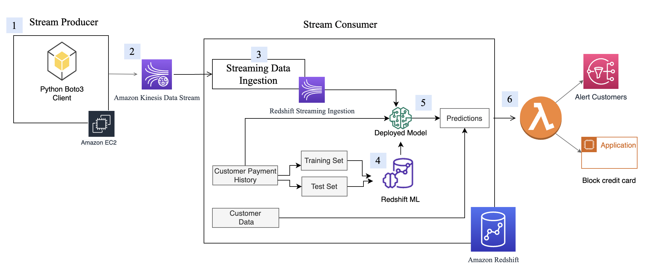
The following figure shows an MSK cluster that is configured to use IAM access control in the demo account. Each producer and consumer application has a quota that determines how much data they can produce or consume in bytes per second. For example, ProducerApp-1 has a produce quota of 1024 bytes/sec, and ConsumerApp-1 and ConsumerApp-2 each have a consume quota of 5120 and 1024 bytes/sec, respectively. It’s important to note that Kafka quotas are set on the Kafka cluster rather than in the client applications.

The preceding figure illustrates how Kafka client applications (ProducerApp-1, ConsumerApp-1, and ConsumerApp-2) access Topic-B in the MSK cluster by assuming write and read IAM roles. The workflow is as follows:
- P1 –
ProducerApp-1(via itsProducerApp-1-RoleIAM role) assumes theTopic-B-Write-RoleIAM role to send messages toTopic-Bin the MSK cluster. - P2 – With the
Topic-B-Write-RoleIAM role assumed,ProducerApp-1begins sending messages toTopic-B. - C1 –
ConsumerApp-1(via itsConsumerApp-1-RoleIAM role) andConsumerApp-2(via itsConsumerApp-2-RoleIAM role) assume theTopic-B-Read-RoleIAM role to read messages fromTopic-Bin the MSK cluster. - C2 – With the
Topic-B-Read-RoleIAM role assumed,ConsumerApp-1andConsumerApp-2start consuming messages fromTopic-B.
ConsumerApp-1 and ConsumerApp-2 are two separate consumer applications. They do not belong to the same consumer group.
Configuring client IDs and understanding authenticated user principal
As explained earlier, Kafka quotas can be configured for specific users, specific client IDs, or both. Let’s explore client ID and user concepts and configurations required for Kafka quota allocation.
Client ID
A client ID representing an application’s logical name can be configured within an application’s code. In Java applications, for example, you can set the producer’s and consumer’s client IDs using ProducerConfig.CLIENT_ID_CONFIG and ConsumerConfig.CLIENT_ID_CONFIG configurations, respectively. The following code snippet illustrates how ProducerApp-1 sets the client ID to this-is-me-producerapp-1 using ProducerConfig.CLIENT_ID_CONFIG:
User
The user refers to an authenticated user principal of the client application in the Kafka cluster with authentication enabled. As shown in the solution architecture, producer and consumer applications assume the Topic-B-Write-Role and Topic-B-Read-Role IAM roles, respectively, to perform write and read operations on Topic-B. Therefore, their authenticated user principal will look like the following IAM identifier:
For more information, refer to IAM identifiers.
The role session name is a string identifier that uniquely identifies a session when IAM principals, federated identities, or applications assume an IAM role. In our case, ProducerApp-1, ConsumerApp-1, and ConsumerApp-2 applications assume an IAM role using the AWS Security Token Service (AWS STS) SDK, and provide a role session name in the AWS STS SDK call. For example, if ProducerApp-1 assumes the Topic-B-Write-Role IAM role and uses this-is-producerapp-1-role-session as its role session name, its authenticated user principal will be as follows:
The following is an example code snippet from the ProducerApp-1 application using this-is-producerapp-1-role-session as the role session name while assuming the Topic-B-Write-Role IAM role using the AWS STS SDK:
Configure network bandwidth (produce and consume) quotas
The following commands configure the produce and consume quotas dynamically for client applications based on their client ID and authenticated user principal in the MSK cluster configured with IAM access control.
The following code configures the produce quota:
The producer_byes_rate refers to the number of messages, in bytes, that a producer client identified by client ID and user is allowed to produce to a single broker per second. The option --command-config points to config_iam.properties, which contains the properties required for IAM access control.
The following code configures the consume quota:
The consumer_bytes_rate refers to the number of messages, in bytes, that a consumer client identified by client ID and user allowed to consume from a single broker per second.
Let’s look at some example quota configuration commands for ProducerApp-1, ConsumerApp-1, and ConsumerApp-2 client applications:
- ProducerApp-1 produce quota configuration – Let’s assume
ProducerApp-1hasthis-is-me-producerapp-1configured as the client ID in the application code and usesthis-is-producerapp-1-role-sessionas the role session name when assuming theTopic-B-Write-RoleIAM role. The following command sets the produce quota forProducerApp-1to 1024 bytes per second:
- ConsumerApp-1 consume quota configuration – Let’s assume
ConsumerApp-1hasthis-is-me-consumerapp-1configured as the client ID in the application code and usesthis-is-consumerapp-1-role-sessionas the role session name when assuming theTopic-B-Read-RoleIAM role. The following command sets the consume quota forConsumerApp-1to 5120 bytes per second:
ConsumerApp-2 consume quota configuration – Let’s assume ConsumerApp-2 has this-is-me-consumerapp-2 configured as the client ID in the application code and uses this-is-consumerapp-2-role-session as the role session name when assuming the Topic-B-Read-Role IAM role. The following command sets the consume quota for ConsumerApp-2 to 1024 bytes per second per broker:
As a result of the preceding commands, the ProducerApp-1, ConsumerApp-1, and ConsumerApp-2 client applications will be throttled by the MSK cluster using IAM access control if they exceed their assigned produce and consume quotas, respectively.
Implement the solution
Part 2 of this series showcases the step-by-step detailed implementation of Kafka quotas configuration with IAM access control along with the sample producer and consumer client applications.
Conclusion
Kafka quotas offer teams the ability to set limits for producer and consumer applications. With Amazon MSK, Kafka quotas serve two important purposes: eliminating guesswork and preventing issues caused by poorly designed producer or consumer applications by limiting their quota, and allocating operational costs of a central streaming data platform across different cost centers and tenants (application and product teams).
In this post, we learned how to configure network bandwidth quotas within Amazon MSK while using IAM access control. We also covered some sample commands and code snippets to clarify how the client ID and authenticated principal are used when configuring quotas. Although we only demonstrated Kafka quotas using IAM access control, you can also configure them using other Amazon MSK-supported authentication mechanisms.
In Part 2 of this series, we demonstrate how to configure network bandwidth quotas with IAM access control in Amazon MSK and provide you with example producer and consumer applications so that you can see them in action.
Check out the following resources to learn more:
- Apache Kafka Quotas
- Providing access to an IAM user in another AWS account that you own
- Amazon MSK IAM access control
- Amazon MSK Library for AWS Identity and Access Management GitHub repo
About the Author
 Vikas Bajaj is a Senior Manager, Solutions Architects, Financial Services at Amazon Web Services. Having worked with financial services organizations and digital native customers, he advises financial services customers in Australia on technology decisions, architectures, and product roadmaps.


 Vikas Bajaj is a Senior Manager, Solutions Architects, Financial Services at Amazon Web Services. With over two decades of experience in financial services and working with digital-native businesses, he advises customers on product design, technology roadmaps, and application architectures.

 Nagarjuna Koduru is a Principal Engineer in AWS, currently working for AWS Managed Streaming For Kafka (MSK). He led the teams that built MSK Serverless and MSK Tiered storage products. He previously led the team in Amazon JustWalkOut (JWO) that is responsible for realtime tracking of shopper locations in the store. He played pivotal role in scaling the stateful stream processing infrastructure to support larger store formats and reducing the overall cost of the system. He has keen interest in stream processing, messaging and distributed storage infrastructure.
 Masudur Rahaman Sayem is a Streaming Data Architect at AWS. He works with AWS customers globally to design and build data streaming architectures to solve real-world business problems. He specializes in optimizing solutions that use streaming data services and NoSQL. Sayem is very passionate about distributed computing.


 Manish Virwani is a Sr. Solutions Architect at AWS. He has more than a decade of experience designing and implementing large-scale big data and analytics solutions. He provides technical guidance, design advice, and thought leadership to some of the key AWS customers and partners.
 Indira Balakrishnan is a Principal Solutions Architect in the AWS Analytics Specialist SA Team. She is passionate about helping customers build cloud-based analytics solutions to solve their business problems using data-driven decisions. Outside of work, she volunteers at her kids’ activities and spends time with her family.
 Sekar Srinivasan is a Sr. Specialist Solutions Architect at AWS focused on Big Data and Analytics. Sekar has over 20 years of experience working with data. He is passionate about helping customers build scalable solutions modernizing their architecture and generating insights from their data. In his spare time he likes to work on non-profit projects focused on underprivileged Children’s education.
 Chandra Dhandapani is a Senior Solutions Architect at AWS, where he specializes in creating solutions for customers in Analytics, AI/ML, and Databases. He has a lot of experience in building and scaling applications across different industries including Healthcare and Fintech. Outside of work, he is an avid traveler and enjoys sports, reading, and entertainment.
 Amit Kumar Agrawal is a Senior Solutions Architect at AWS, based out of San Francisco Bay Area. He works with large strategic ISV customers to architect cloud solutions that address their business challenges. During his free time he enjoys exploring the outdoors with his family.
 Viral Shah is a Analytics Sales Specialist working with AWS for 5 years helping customers to be successful in their data journey. He has over 20+ years of experience working with enterprise customers and startups, primarily in the data and database space. He loves to travel and spend quality time with his family.


 Ali Alemi is a Streaming Specialist Solutions Architect at AWS. Ali advises AWS customers with architectural best practices and helps them design real-time analytics data systems that are reliable, secure, efficient, and cost-effective. He works backward from customers’ use cases and designs data solutions to solve their business problems. Prior to joining AWS, Ali supported several public sector customers and AWS consulting partners in their application modernization journey and migration to the cloud.
 Rajeev Chakrabarti is a Kinesis specialist solutions architect.


 Masudur Rahaman Sayem is a Streaming Data Architect at AWS. He works with AWS customers globally to design and build data streaming architectures to solve real-world business problems. He specializes in optimizing solutions that use streaming data services and NoSQL. Sayem is very passionate about distributed computing.
 Akeef Khan is a Solutions Architect at Amazon Web Services. He helps SMB Greenfield customers adopt the cloud. Whilst being a generalist SA, Akeef is passionate about networking.


 Mahesh Pasupuleti is a VP of Data & Machine Learning Engineering at Poshmark. He has helped several startups succeed in different domains, including media streaming, healthcare, the financial sector, and marketplaces. He loves software engineering, building high performance teams, and strategy, and enjoys gardening and playing badminton in his free time.
 Gaurav Shah is Director of Data Engineering and ML at Poshmark. He and his team help build data-driven solutions to drive growth at Poshmark.
 Raghu Mannam is a Sr. Solutions Architect at AWS in San Francisco. He works closely with late-stage startups, many of which have had recent IPOs. His focus is end-to-end solutioning including security, DevOps automation, resilience, analytics, machine learning, and workload optimization in the cloud.
 Deepesh Malviya is Solutions Architect Manager on the AWS Data Lab team. He and his team help customers architect and build data, analytics, and machine learning solutions to accelerate their key initiatives as part of the AWS Data Lab.


 Kalyan Janaki is Senior Big Data & Analytics Specialist with Amazon Web Services. He helps customers architect and build highly scalable, performant, and secure cloud-based solutions on AWS.


 Ajit Puthiyavettle is a Solution Architect working with enterprise clients, architecting solutions to achieve business outcomes. He is passionate about solving customer challenges with innovative solutions. His experience is with leading DevOps and security teams for enterprise and SaaS (Software as a Service) companies. Recently he is focussed on helping customers with Security, ML and HCLS workload.
 Usama Naseem is a Senior Product Manager for Amazon MSK and focuses on MSK Serverless. Previously, he held product management roles for AWS Lambda and Amazon Fresh. He is passionate about giving customers the tools to build real-time applications in the cloud. Outside of work, he continues to be under the delusion that he will be the best squash player in the world one day.


 Babu Srinivasan is a Senior Partner Solutions Architect at MongoDB. In his current role, he is working with AWS to build the technical integrations and reference architectures for the AWS and MongoDB solutions. He has more than two decades of experience in Database and Cloud technologies . He is passionate about providing technical solutions to customers working with multiple Global System Integrators(GSIs) across multiple geographies.
 Robert Walters is currently a Senior Product Manager at MongoDB. Previous to MongoDB, Rob spent 17 years at Microsoft working in various roles, including program management on the SQL Server team, consulting, and technical pre-sales. Rob has co-authored three patents for technologies used within SQL Server and was the lead author of several technical books on SQL Server. Rob is currently an active blogger on MongoDB Blogs.