Tag Archives: networking

A story about AF_XDP, network namespaces and a cookie

Post Syndicated from Bastien Dhiver original https://blog.cloudflare.com/a-story-about-af-xdp-network-namespaces-and-a-cookie/

A story about AF_XDP, network namespaces and a cookie

A story about AF_XDP, network namespaces and a cookie

A crash in a development version of flowtrackd (the daemon that powers our Advanced TCP Protection) highlighted the fact that libxdp (and specifically the AF_XDP part) was not Linux network namespace aware.

This blogpost describes the debugging journey to find the bug, as well as a fix.

flowtrackd is a volumetric denial of service defense mechanism that sits in the Magic Transit customer’s data path and protects the network from complex randomized TCP floods. It does so by challenging TCP connection establishments and by verifying that TCP packets make sense in an ongoing flow.

It uses the Linux kernel AF_XDP feature to transfer packets from a network device in kernel space to a memory buffer in user space without going through the network stack. We use most of the helper functions of the C libbpf with the Rust bindings to interact with AF_XDP.

In our setup, both the ingress and the egress network interfaces are in different network namespaces. When a packet is determined to be valid (after a challenge or under some thresholds), it is forwarded to the second network interface.

For the rest of this post the network setup will be the following:

A story about AF_XDP, network namespaces and a cookie

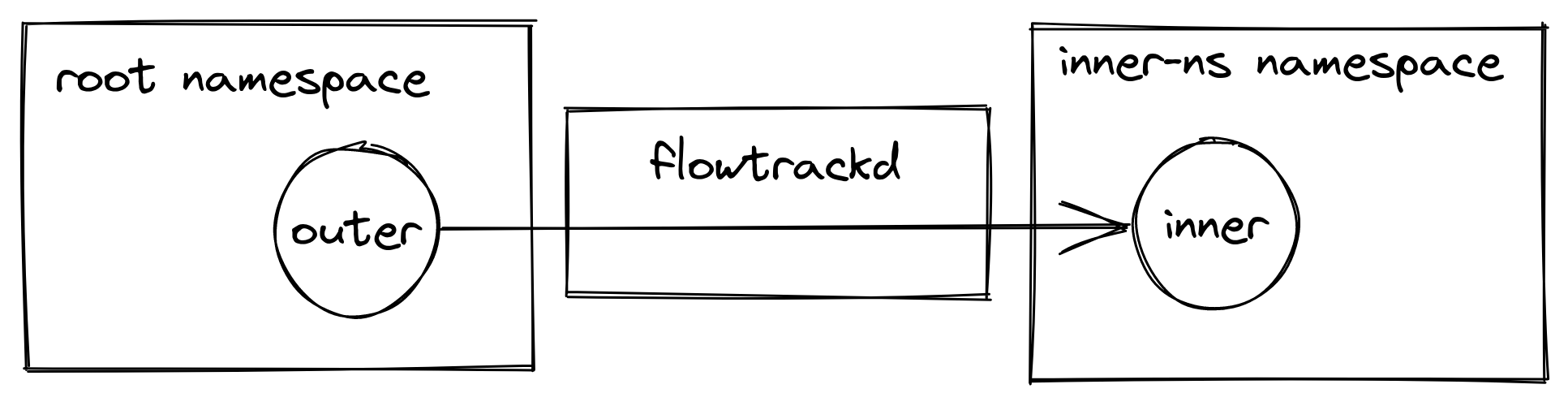
e.g. eyeball packets arrive at the outer device in the root network namespace, they are picked up by flowtrackd and then forwarded to the inner device in the inner-ns namespace.

AF_XDP

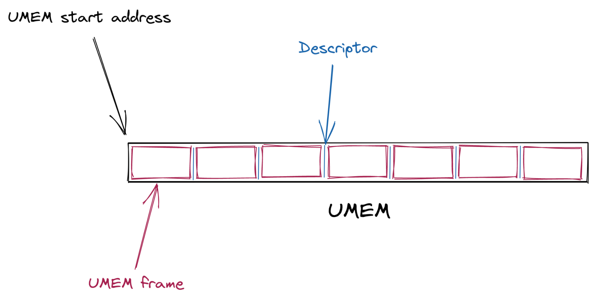
The kernel and the userspace share a memory buffer called the UMEM. This is where packet bytes are written to and read from.

The UMEM is split in contiguous equal-sized “frames” that are referenced by “descriptors” which are just offsets from the start address of the UMEM.

A story about AF_XDP, network namespaces and a cookie

The interactions and synchronization between the kernel and userspace happen via a set of queues (circular buffers) as well as a socket from the AF_XDP family.

Most of the work is about managing the ownership of the descriptors. Which descriptors the kernel owns and which descriptors the userspace owns.

The interface provided for the ownership management are a set of queues:

Queue User space Kernel space Content description
COMPLETION Consumes Produces Frame descriptors that have successfully been transmitted
FILL Produces Consumes Frame descriptors ready to get new packet bytes written to
RX Consumes Produces Frame descriptors of a newly received packet
TX Produces Consumes Frame descriptors to be transmitted

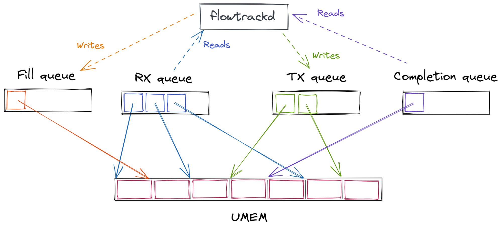
When the UMEM is created, a FILL and a COMPLETION queue are associated with it.

An RX and a TX queue are associated with the AF_XDP socket (abbreviated Xsk) at its creation. This particular socket is bound to a network device queue id. The userspace can then poll() on the socket to know when new descriptors are ready to be consumed from the RX queue and to let the kernel deal with the descriptors that were set on the TX queue by the application.

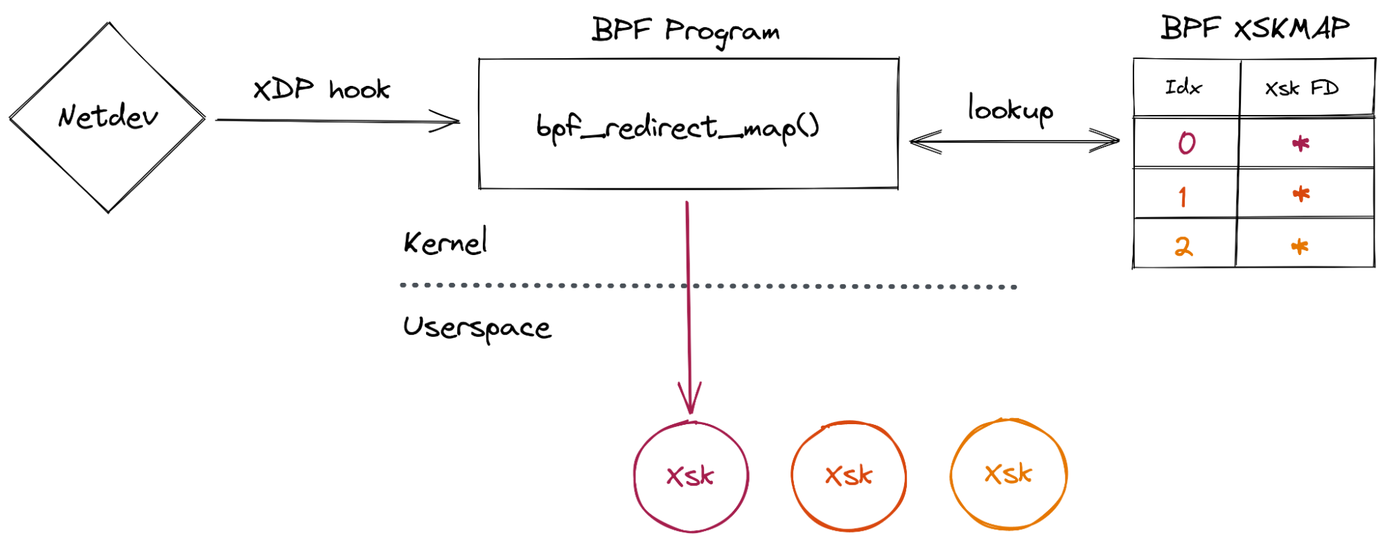
The last plumbing operation to be done to use AF_XDP is to load a BPF program attached with XDP on the network device we want to interact with and insert the Xsk file descriptor into a BPF map (of type XSKMAP). Doing so will enable the BPF program to redirect incoming packets (with the bpf_redirect_map() function) to a specific socket that we created in userspace:

A story about AF_XDP, network namespaces and a cookie

Once everything has been allocated and strapped together, what I call “the descriptors dance” can start. While this has nothing to do with courtship behaviors it still requires a flawless execution:

When the kernel receives a packet (more specifically the device driver), it will write the packet bytes to a UMEM frame (from a descriptor that the userspace put in the FILL queue) and then insert the frame descriptor in the RX queue for the userspace to consume. The userspace can then read the packet bytes from the received descriptor, take a decision, and potentially send it back to the kernel for transmission by inserting the descriptor in the TX queue. The kernel can then transmit the content of the frame and put the descriptor from the TX to the COMPLETION queue. The userspace can then “recycle” this descriptor in the FILL or TX queue.

The overview of the queue interactions from the application perspective is represented on the following diagram (note that the queues contain descriptors that point to UMEM frames):

A story about AF_XDP, network namespaces and a cookie

flowtrackd I/O rewrite project

To increase flowtrackd performance and to be able to scale with the growth of the Magic Transit product we decided to rewrite the I/O subsystem.

There will be a public blogpost about the technical aspects of the rewrite.

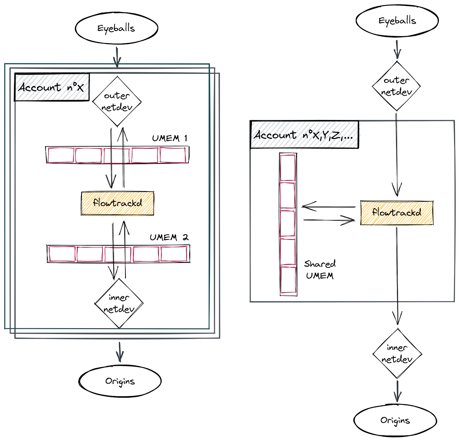
Prior to the rewrite, each customer had a dedicated flowtrackd instance (Unix process) that attached itself to dedicated network devices. A dedicated UMEM was created per network device (see schema on the left side below). The packets were copied from one UMEM to the other.

In this blogpost, we will only focus on the new usage of the AF_XDP shared UMEM feature which enables us to handle all customer accounts with a single flowtrackd instance per server and with a single shared UMEM (see schema on the right side below).

A story about AF_XDP, network namespaces and a cookie

The Linux kernel documentation describes the additional plumbing steps to share a UMEM across multiple AF_XDP sockets:

A story about AF_XDP, network namespaces and a cookie

Followed by the instructions for our use case:

A story about AF_XDP, network namespaces and a cookie

Hopefully for us a helper function in libbpf does it all for us: xsk_socket__create_shared()

A story about AF_XDP, network namespaces and a cookie

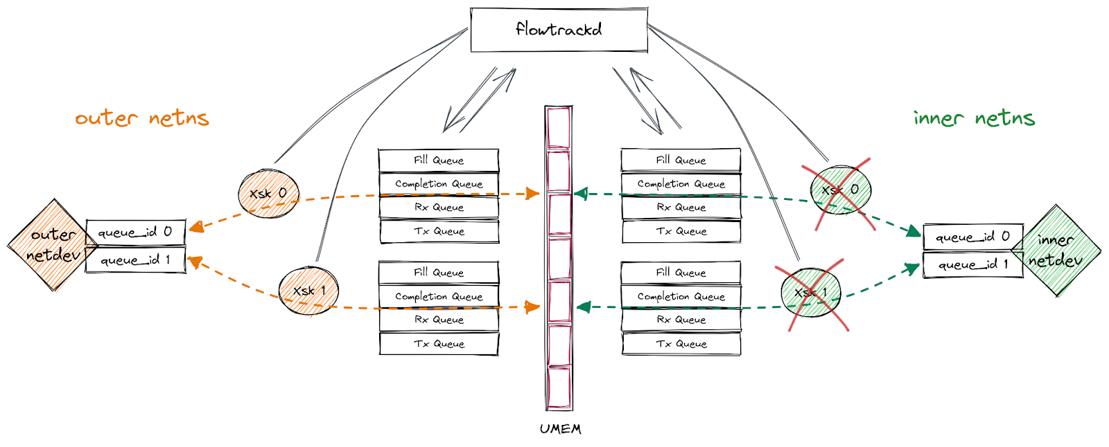
The final setup is the following: Xsks are created for each queue of the devices in their respective network namespaces. flowtrackd then handles the descriptors like a puppeteer while applying our DoS mitigation logic on the packets that they reference with one exception… (notice the red crosses on the diagram):

A story about AF_XDP, network namespaces and a cookie

What “Invalid argument” ??!

We were happily near the end of the rewrite when, suddenly, after porting our integration tests in the CI, flowtrackd crashed!

The following errors was displayed:

[...]
Thread 'main' panicked at 'failed to create Xsk: Libbpf("Invalid argument")', flowtrack-io/src/packet_driver.rs:144:22
note: run with `RUST_BACKTRACE=1` environment variable to display a backtrace

According to the line number, the first socket was created with success and flowtrackd crashed when the second Xsk was created:

A story about AF_XDP, network namespaces and a cookie

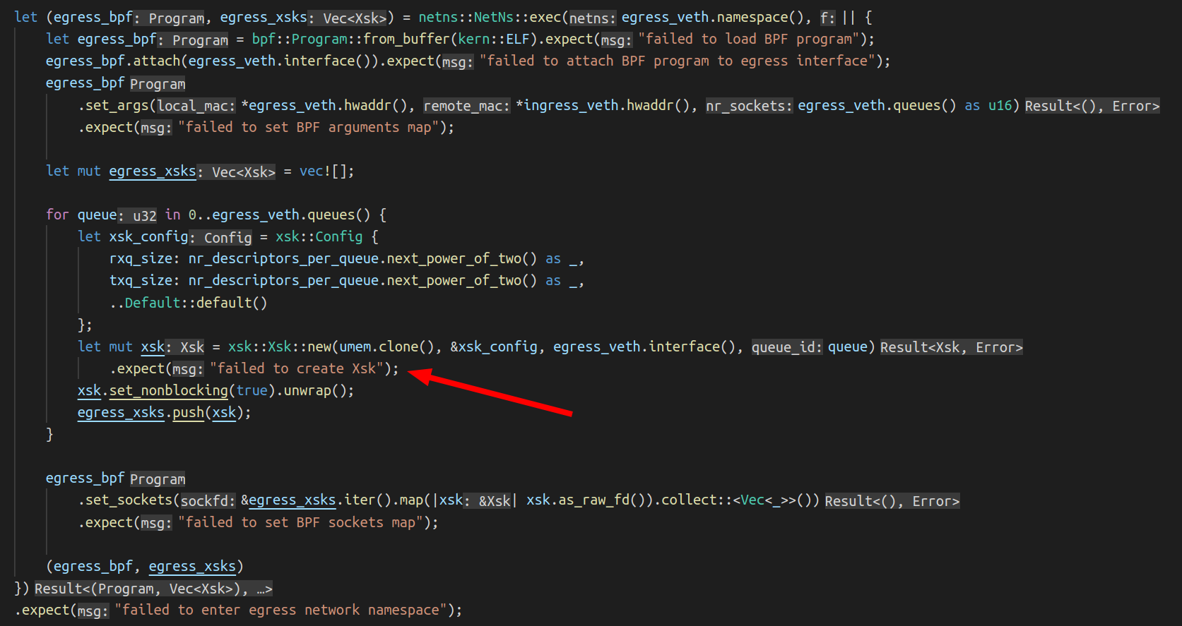
Here is what we do: we enter the network namespace where the interface sits, load and attach the BPF program and for each queue of the interface, we create a socket. The UMEM and the config parameters are the same with the ingress Xsk creation. Only the ingress_veth and egress_veth are different.

This is what the code to create an Xsk looks like:

A story about AF_XDP, network namespaces and a cookie

The call to the libbpf function xsk_socket__create_shared() didn’t return 0.

The libxdp manual page doesn’t help us here…

Which argument is “invalid”? And why is this error not showing up when we run flowtrackd locally but only in the CI?

We can try to reproduce locally with a similar network setup script used in the CI:

#!/bin/bash
 
set -e -u -x -o pipefail
 
OUTER_VETH=${OUTER_VETH:=outer}
TEST_NAMESPACE=${TEST_NAMESPACE:=inner-ns}
INNER_VETH=${INNER_VETH:=inner}
QUEUES=${QUEUES:=$(grep -c ^processor /proc/cpuinfo)}
 
ip link delete $OUTER_VETH &>/dev/null || true
ip netns delete $TEST_NAMESPACE &>/dev/null || true
ip netns add $TEST_NAMESPACE
ip link \
  add name $OUTER_VETH numrxqueues $QUEUES numtxqueues $QUEUES type veth \
  peer name $INNER_VETH netns $TEST_NAMESPACE numrxqueues $QUEUES numtxqueues $QUEUES
ethtool -K $OUTER_VETH tx off rxvlan off txvlan off
ip link set dev $OUTER_VETH up
ip addr add 169.254.0.1/30 dev $OUTER_VETH
ip netns exec $TEST_NAMESPACE ip link set dev lo up
ip netns exec $TEST_NAMESPACE ethtool -K $INNER_VETH tx off rxvlan off txvlan off
ip netns exec $TEST_NAMESPACE ip link set dev $INNER_VETH up
ip netns exec $TEST_NAMESPACE ip addr add 169.254.0.2/30 dev $INNER_VETH

For the rest of the blogpost, we set the number of queues per interface to 1. If you have questions about the set command in the script, check this out.

Not much success triggering the error.

What differs between my laptop setup and the CI setup?

I managed to find out that when the outer and inner interface index numbers are the same then it crashes. Even though the interfaces don’t have the same name, and they are not in the same network namespace. When the tests are run by the CI, both interfaces got index number 5 which was not the case on my laptop since I have more interfaces:

$ ip -o link | cut -d' ' -f1,2
1: lo:
2: wwan0:
3: wlo1:
4: virbr0:
7: br-ead14016a14c:
8: docker0:
9: br-bafd94c79ff4:
29: outer@if2:

We can edit the script to set a fixed interface index number:

ip link \
  add name $OUTER_VETH numrxqueues $QUEUES numtxqueues $QUEUES index 4242 type veth \
  peer name $INNER_VETH netns $TEST_NAMESPACE numrxqueues $QUEUES numtxqueues $QUEUES index 4242

And we can now reproduce the issue locally!

Interesting observation: I was not able to reproduce this issue with the previous flowtrackd version. Is this somehow related to the shared UMEM feature that we are now using?

Back to the “invalid” argument. strace to the rescue:

sudo strace -f -x ./flowtrackd -v -c flowtrackd.toml --ingress outer --egress inner --egress-netns inner-ns
 
[...]
 
// UMEM allocation + first Xsk creation
 
[pid 389577] brk(0x55b485819000)        = 0x55b485819000
[pid 389577] mmap(NULL, 8396800, PROT_READ|PROT_WRITE, MAP_PRIVATE|MAP_ANONYMOUS, -1, 0) = 0x7f85037fe000
 
[pid 389577] socket(AF_XDP, SOCK_RAW|SOCK_CLOEXEC, 0) = 9
[pid 389577] setsockopt(9, SOL_XDP, XDP_UMEM_REG, "\x00\xf0\x7f\x03\x85\x7f\x00\x00\x00\x00\x80\x00\x00\x00\x00\x00\x00\x08\x00\x00\x00\x00\x00\x00\x00\x00\x00\x00\x00\x00\x00\x00", 32) = 0
[pid 389577] setsockopt(9, SOL_XDP, XDP_UMEM_FILL_RING, [2048], 4) = 0
[pid 389577] setsockopt(9, SOL_XDP, XDP_UMEM_COMPLETION_RING, [2048], 4) = 0
[pid 389577] getsockopt(9, SOL_XDP, XDP_MMAP_OFFSETS, "\x00\x00\x00\x00\x00\x00\x00\x00\x80\x00\x00\x00\x00\x00\x00\x00\x40\x01\x00\x00\x00\x00\x00\x00\xc4\x00\x00\x00\x00\x00\x00\x00"..., [128]) = 0
[pid 389577] mmap(NULL, 16704, PROT_READ|PROT_WRITE, MAP_SHARED|MAP_POPULATE, 9, 0x100000000) = 0x7f852801b000
[pid 389577] mmap(NULL, 16704, PROT_READ|PROT_WRITE, MAP_SHARED|MAP_POPULATE, 9, 0x180000000) = 0x7f8528016000
[...]
[pid 389577] setsockopt(9, SOL_XDP, XDP_RX_RING, [2048], 4) = 0
[pid 389577] setsockopt(9, SOL_XDP, XDP_TX_RING, [2048], 4) = 0
[pid 389577] getsockopt(9, SOL_XDP, XDP_MMAP_OFFSETS, "\x00\x00\x00\x00\x00\x00\x00\x00\x80\x00\x00\x00\x00\x00\x00\x00\x40\x01\x00\x00\x00\x00\x00\x00\xc4\x00\x00\x00\x00\x00\x00\x00"..., [128]) = 0
[pid 389577] mmap(NULL, 33088, PROT_READ|PROT_WRITE, MAP_SHARED|MAP_POPULATE, 9, 0) = 0x7f850377e000
[pid 389577] mmap(NULL, 33088, PROT_READ|PROT_WRITE, MAP_SHARED|MAP_POPULATE, 9, 0x80000000) = 0x7f8503775000
[pid 389577] bind(9, {sa_family=AF_XDP, sa_data="\x08\x00\x92\x10\x00\x00\x00\x00\x00\x00\x00\x00\x00\x00"}, 16) = 0
 
[...]
 
// Second Xsk creation
 
[pid 389577] socket(AF_XDP, SOCK_RAW|SOCK_CLOEXEC, 0) = 62
[...]
[pid 389577] setsockopt(62, SOL_XDP, XDP_RX_RING, [2048], 4) = 0
[pid 389577] setsockopt(62, SOL_XDP, XDP_TX_RING, [2048], 4) = 0
[pid 389577] getsockopt(62, SOL_XDP, XDP_MMAP_OFFSETS, "\x00\x00\x00\x00\x00\x00\x00\x00\x80\x00\x00\x00\x00\x00\x00\x00\x40\x01\x00\x00\x00\x00\x00\x00\xc4\x00\x00\x00\x00\x00\x00\x00"..., [128]) = 0
[pid 389577] mmap(NULL, 33088, PROT_READ|PROT_WRITE, MAP_SHARED|MAP_POPULATE, 62, 0) = 0x7f85036e4000
[pid 389577] mmap(NULL, 33088, PROT_READ|PROT_WRITE, MAP_SHARED|MAP_POPULATE, 62, 0x80000000) = 0x7f85036db000
[pid 389577] bind(62, {sa_family=AF_XDP, sa_data="\x01\x00\x92\x10\x00\x00\x00\x00\x00\x00\x09\x00\x00\x00"}, 16) = -1 EINVAL (Invalid argument)
 
[pid 389577] munmap(0x7f85036db000, 33088) = 0
[pid 389577] munmap(0x7f85036e4000, 33088) = 0
[pid 389577] close(62)                  = 0
[pid 389577] write(2, "thread '", 8thread ')    = 8
[pid 389577] write(2, "main", 4main)        = 4
[pid 389577] write(2, "' panicked at '", 15' panicked at ') = 15
[pid 389577] write(2, "failed to create Xsk: Libbpf(\"In"..., 48failed to create Xsk: Libbpf("Invalid argument")) = 48
[...]

Ok, the second bind() syscall returns the EINVAL value.

The sa_family is the right one. Is something wrong with sa_data="\x01\x00\x92\x10\x00\x00\x00\x00\x00\x00\x09\x00\x00\x00" ?

Let’s look at the bind syscall kernel code:

err = sock->ops->bind(sock, (struct sockaddr *) &address, addrlen);

The bind function of the protocol specific socket operations gets called. Searching for “AF_XDP” in the code, we quickly found the bind function call related to the AF_XDP socket address family.

So, where in the syscall could this value be returned?

First, let’s examine the syscall parameters to see if the libbpf xsk_socket__create_shared() function sets weird values for us.

We use the pahole tool to print the structure definitions:

$ pahole sockaddr
struct sockaddr {
        sa_family_t                sa_family;            /*     0     2 */
        char                       sa_data[14];          /*     2    14 */
 
        /* size: 16, cachelines: 1, members: 2 */
        /* last cacheline: 16 bytes */
};
 
$ pahole sockaddr_xdp
struct sockaddr_xdp {
        __u16                      sxdp_family;          /*     0     2 */
        __u16                      sxdp_flags;           /*     2     2 */
        __u32                      sxdp_ifindex;         /*     4     4 */
        __u32                      sxdp_queue_id;        /*     8     4 */
        __u32                      sxdp_shared_umem_fd;  /*    12     4 */
 
        /* size: 16, cachelines: 1, members: 5 */
        /* last cacheline: 16 bytes */
};

Translation of the arguments of the bind syscall (the 14 bytes of sa_data) for the first bind() call:

Struct member Big Endian value Decimal Meaning Observation
sxdp_flags \x08\x00 8 XDP_USE_NEED_WAKEUP expected
sxdp_ifindex \x92\x10\x00\x00 4242 The network interface index expected
sxdp_queue_id \x00\x00\x00\x00 0 The network interface queue id expected
sxdp_shared_umem_fd \x00\x00\x00\x00 0 The umem is not shared yet expected

Second bind() call:

Struct member Big Endian value Decimal Meaning Observation
sxdp_flags \x01\x00 1 XDP_SHARED_UMEM expected
sxdp_ifindex \x92\x10\x00\x00 4242 The network interface index expected
sxdp_queue_id \x00\x00\x00\x00 0 The network interface queue id expected
sxdp_shared_umem_fd \x09\x00\x00\x00 9 File descriptor of the first AF_XDP socket associated to the UMEM expected

The arguments look good…

We could statically try to infer where the EINVAL was returned looking at the source code. But this analysis has its limits and can be error-prone.

Overall, it seems that the network namespaces are not taken into account somewhere because it seems that there is some confusion with the interface indexes.

Is the issue on the kernel-side?

Digging deeper

It would be nice if we had step-by-step runtime inspection of code paths and variables.

Let’s:

  • Compile a Linux kernel version closer to the one used on our servers (5.15) with debug symbols.
  • Generate a root filesystem for the kernel to boot.
  • Boot in QEMU.
  • Attach gdb to it and set a breakpoint on the syscall.
  • Check where the EINVAL value is returned.

We could have used buildroot with a minimal reproduction code, but it wasn’t funny enough. Instead, we install a minimal Ubuntu and load our custom kernel. This has the benefit of having a package manager if we need to install other debugging tools.

Let’s install a minimal Ubuntu server 21.10 (with ext4, no LVM and a ssh server selected in the installation wizard):

qemu-img create -f qcow2 ubuntu-21.10-live-server-amd64.qcow2 20G
 
qemu-system-x86_64 \
  -smp $(nproc) \
  -m 4G \
  -hda ubuntu-21.10-live-server-amd64.qcow2 \
  -cdrom /home/bastien/Downloads/ubuntu-21.10-live-server-amd64.iso \
  -enable-kvm \
  -cpu host \
  -net nic,model=virtio \
  -net user,hostfwd=tcp::10022-:22

And then build a kernel (link and link) with the following changes in the menuconfig:

  • Cryptographic API -> Certificates for signature checking -> Provide system-wide ring of trusted keys
    • change the additional string to be EMPTY ("")
  • Device drivers -> Network device support -> Virtio network driver
    • Set to Enable
  • Device Drivers -> Network device support -> Virtual ethernet pair device
    • Set to Enable
  • Device drivers -> Block devices -> Virtio block driver
    • Set to Enable

git clone git://git.kernel.org/pub/scm/linux/kernel/git/stable/linux.git && cd linux/
git checkout v5.15
make menuconfig
make -j$(nproc) bzImage

We can now run Ubuntu with our custom kernel waiting for gdb to be connected:

qemu-system-x86_64 \
  -kernel /home/bastien/work/linux/arch/x86_64/boot/bzImage \
  -append "root=/dev/sda2 console=ttyS0 nokaslr" \
  -nographic \
  -smp $(nproc) \
  -m 8G \
  -hda ubuntu-21.10-live-server-amd64.qcow2 \
  -boot c \
  -cpu host \
  -net nic,model=virtio \
  -net user,hostfwd=tcp::10022-:22 \
  -enable-kvm \
  -s -S

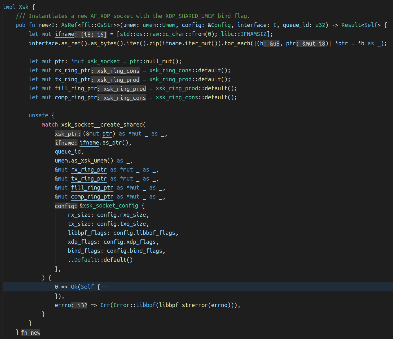
And we can fire up gdb and set a breakpoint on the xsk_bind function:

$ gdb  -ex "add-auto-load-safe-path $(pwd)" -ex "file vmlinux" -ex "target remote :1234" -ex "hbreak start_kernel" -ex "continue"
(gdb) b xsk_bind
(gdb) continue

After executing the network setup script and running flowtrackd, we hit the xsk_bind breakpoint:

A story about AF_XDP, network namespaces and a cookie

We continue to hit the second xsk_bind breakpoint (the one that returns EINVAL) and after a few next and step commands, we find which function returned the EINVAL value:

A story about AF_XDP, network namespaces and a cookie

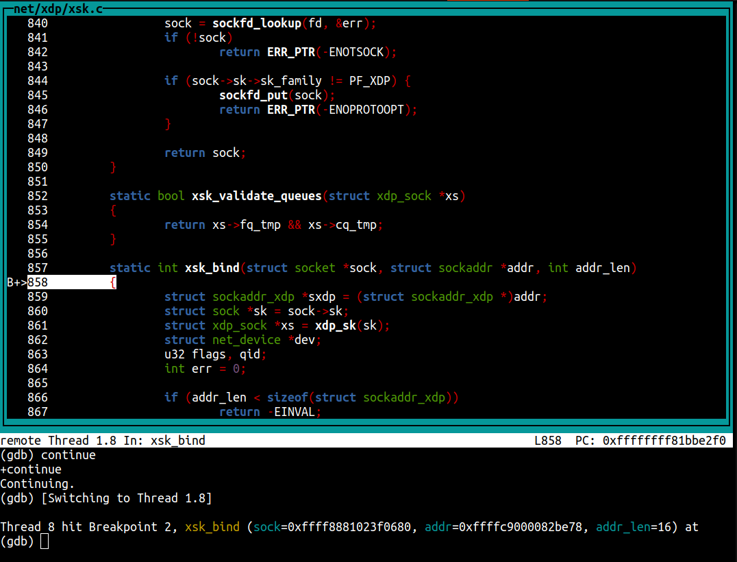
In our Rust code, we allocate a new FILL and a COMPLETION queue for each queue id of the device prior to calling xsk_socket__create_shared(). Why are those set to NULL? Looking at the code, pool->fq comes from a struct field named fq_tmp that is accessed from the sock pointer (print ((struct xdp_sock *)sock->sk)->fq_tmp). The field is set in the first call to xsk_bind() but isn’t in the second call. We note that at the end of the xsk_bind() function, fq_tmp and cq_tmp are set to NULL as per this comment: “FQ and CQ are now owned by the buffer pool and cleaned up with it.”.

Something is definitely going wrong in libbpf because the FILL queue and COMPLETION queue pointers are missing.

Back to the libbpf xsk_socket__create_shared() function to check where the queues are set for the socket and we quickly notice two functions that interact with the FILL and COMPLETION queues:

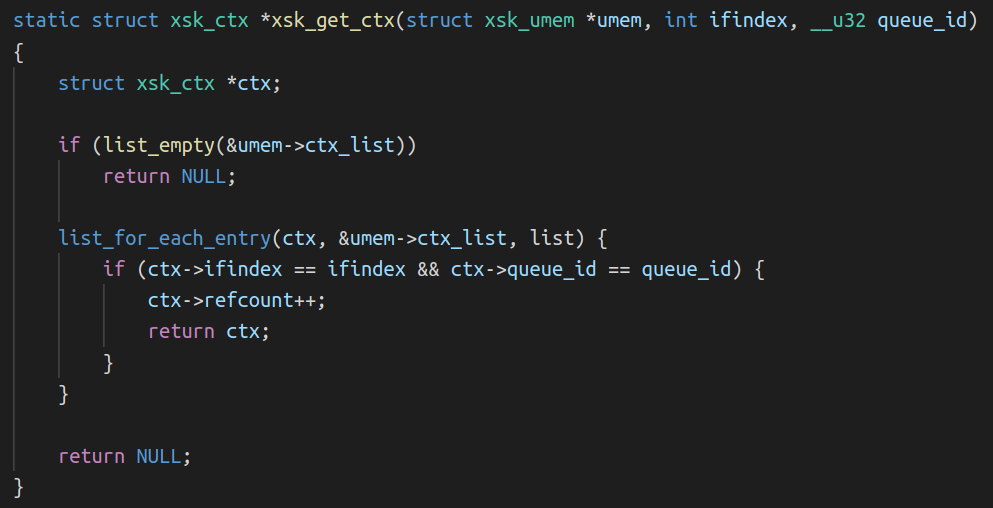
The first function called is xsk_get_ctx():

A story about AF_XDP, network namespaces and a cookie

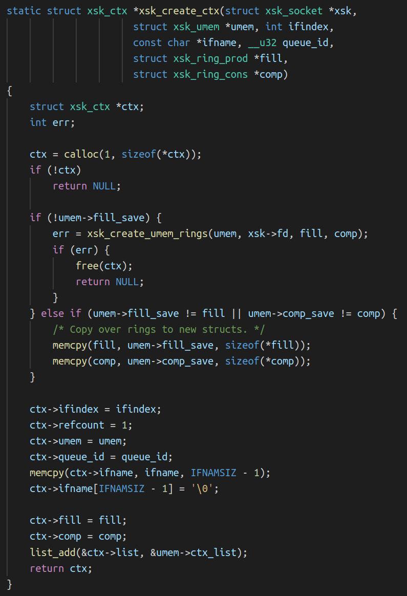
The second is xsk_create_ctx():

A story about AF_XDP, network namespaces and a cookie

Remembering our setup, can you spot what the issue is?

The bug / missing feature

The issue is in the comparison performed in the xsk_get_ctx() to find the right socket context structure associated with the (ifindex, queue_id) pair in the linked-list. The UMEM being shared across Xsks, the same umem->ctx_list linked list head is used to find the sockets that use this UMEM. Remember that in our setup, flowtrackd attaches itself to two network devices that live in different network namespaces. Using the interface index and the queue_id to find the right context (FILL and COMPLETION queues) associated to a socket is not sufficient because another network interface with the same interface index can exist at the same time in another network namespace.

What can we do about it?

We need to tell apart two network devices “system-wide”. That means across the network namespace boundaries.

Could we fetch and store the network namespace inode number of the current process (stat -c%i -L /proc/self/ns/net) at the context creation and then use it in the comparison? According to man 7 inode: “Each file in a filesystem has a unique inode number. Inode numbers are guaranteed to be unique only within a filesystem”. However, inode numbers can be reused:

# ip netns add a
# stat -c%i /run/netns/a
4026532570
# ip netns delete a
# ip netns add b
# stat -c%i /run/netns/b
4026532570

Here are our options:

  • Do a quick hack to ensure that the interface indexes are not the same (as done in the integration tests).
  • Explain our use case to the libbpf maintainers and see how the API for the xsk_socket__create_shared() function should change. It could be possible to pass an opaque “cookie” as a parameter at the socket creation and pass it to the functions that access the socket contexts.
  • Take our chances and look for Linux patches that contain the words “netns” and “cookie”

Well, well, well: [PATCH bpf-next 3/7] bpf: add netns cookie and enable it for bpf cgroup hooks

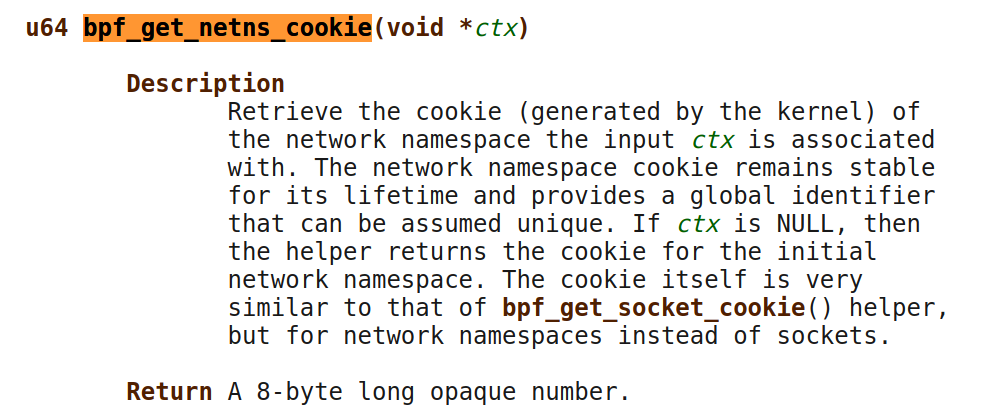
This is almost what we need! This patch adds a kernel function named bpf_get_netns_cookie() that would get us the network namespace cookie linked to a socket:

A story about AF_XDP, network namespaces and a cookie

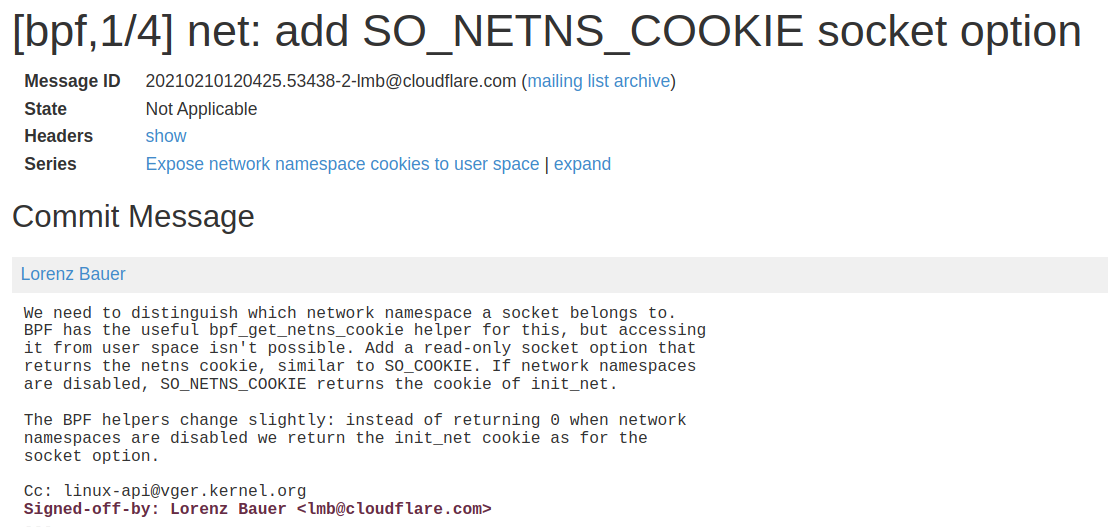
A second patch enables us to get this cookie from userspace:

A story about AF_XDP, network namespaces and a cookie

I know this Lorenz from somewhere 😀

Note that this patch was shipped with the Linux v5.14 release.

We have more guaranties now:

  • The cookie is generated for us by the kernel.
  • There is a strong bound to the socket from its creation (the netns cookie value is present in the socket structure).
  • The network namespace cookie remains stable for its lifetime.
  • It provides a global identifier that can be assumed unique and not reused.

A patch

At the socket creation, we retrieve the netns_cookie from the Xsk file descriptor with getsockopt(), insert it in the xsk_ctx struct and add it in the comparison performed in xsk_get_ctx().

Our initial patch was tested on Linux v5.15 with libbpf v0.8.0.

Testing the patch

We keep the same network setup script, but we set the number of queues per interface to two (QUEUES=2). This will help us check that two sockets created in the same network namespace have the same netns_cookie.

After recompiling flowtrackd to use our patched libbpf, we can run it inside our guest with gdb and set breakpoints on xsk_get_ctx as well as xsk_create_ctx. We now have two instances of gdb running at the same time, one debugging the system and the other debugging the application running in that system. Here is the gdb guest view:

A story about AF_XDP, network namespaces and a cookie

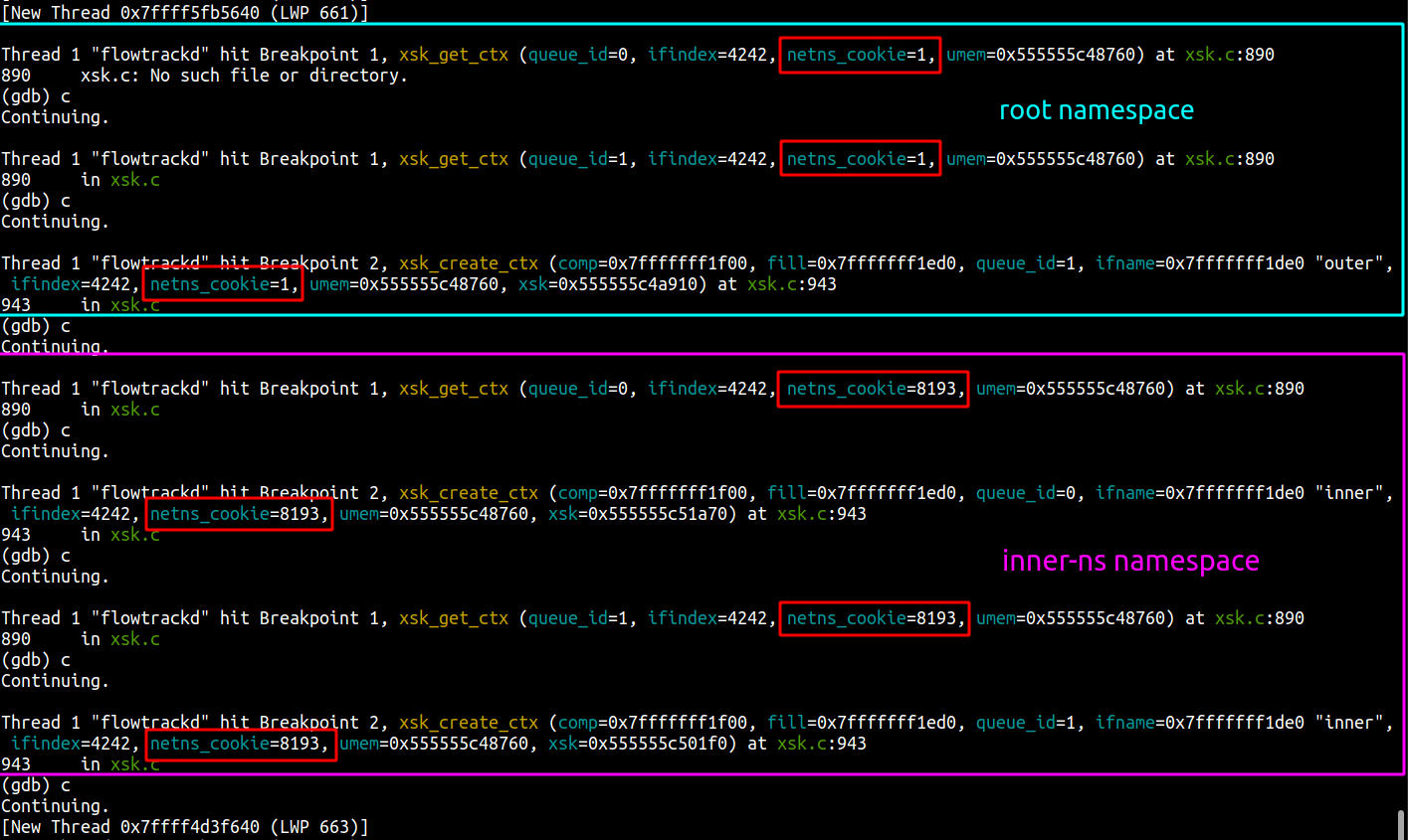
Here is the gdb system view:

A story about AF_XDP, network namespaces and a cookie

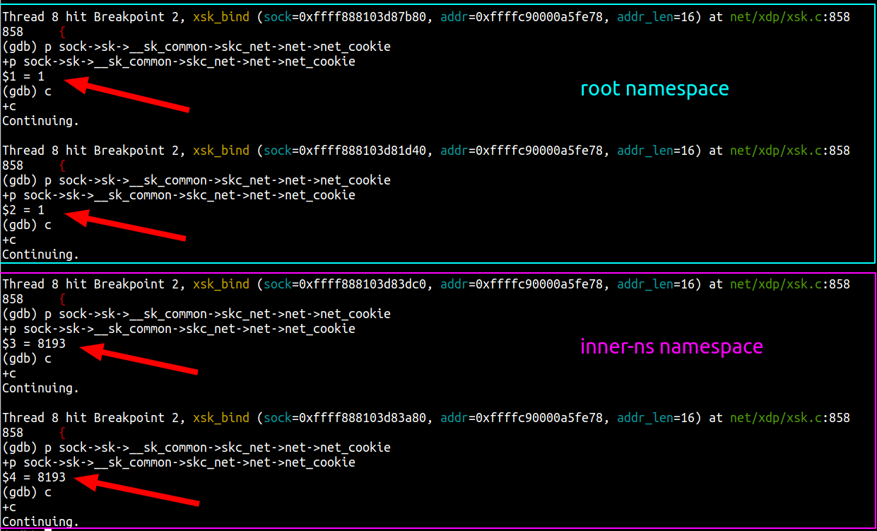
We can see that the netns_cookie value for the first two Xsks is 1 (root namespace) and the net_cookie value for the two other Xsks is 8193 (inner-ns namespace).

flowtrackd didn’t crash and is behaving as expected. It works!

Conclusion

Situation

Creating AF_XDP sockets with the XDP_SHARED_UMEM flag set fails when the two devices’ ifindex (and the queue_id) are the same. This can happen with devices in different network namespaces.

In the shared UMEM mode, each Xsk is expected to have a dedicated fill and completion queue. Context data about those queues are set by libbpf in a linked-list stored by the UMEM object. The comparison performed to pick the right context in the linked-list only takes into account the device ifindex and the queue_id which can be the same when devices are in different network namespaces.

Resolution

We retrieve the netns_cookie associated with the socket at its creation and add it in the comparison operation.

The fix has been submitted and merged in libxdp which is where the AF_XDP parts of libbpf now live.

We’ve also backported the fix in libbpf and updated the libbpf-sys Rust crate accordingly.

Configuring low latency connectivity between AWS Outposts rack and on-premises data using CoIP

Post Syndicated from Sheila Busser original https://aws.amazon.com/blogs/compute/configuring-low-latency-connectivity-between-aws-outposts-rack-using-coip-and-on-premises-data/

This blog post is written by, Leonardo Azize Martins, Cloud Infrastructure Architect, Professional Services.

AWS Outposts rack enables applications that need to run on-premises due to low latency, local data processing, or local data storage needs by connecting Outposts rack to your on-premises network via the local gateway (LGW).

Each Outpost rack includes a local gateway to provide low latency connectivity between the Outpost and any local data sources, end users, local machinery and equipment, or local databases. If you have an Outpost rack, you can include a local gateway as the target in your VPC subnet route table where the destination is your on-premises network. Local gateways are only available for Outposts rack and can only be used in route tables where the VPC has been associated with an LGW.

In a previous blog post on connecting AWS Outposts to on-premises data sources, you learned the different use cases to use AWS Outposts connected with your local network. In this post, you will dive deep into local gateway usage and specific details about it. You will learn how to use Outpost local gateway when it is configured as Customer-owned IP addresses (CoIP) mode. You will also learn how to integrate it with your Amazon Virtual Private Cloud (Amazon VPC) and how different routes work regarding Amazon Elastic Compute Cloud (Amazon EC2) instances running on Outposts.

Overview of solution

The primary role of a local gateway is to provide connectivity from an Outpost to your local on-premises LAN. It also provides AWS Outposts connectivity to the internet through your on-premises network via the LGW, so you don’t need to rely on an internet gateway (IGW). The local gateway can also provide a data plane path back to the AWS Region. If you already have connectivity between your LAN and the Region through AWS Site-to-Site VPN or AWS Direct Connect, you can use the same path to connect from the Outpost to the AWS Region privately.

Outpost subnet

Public subnets and private subnets are important concepts to understand for Outposts networking. A public subnet has a route to an internet gateway. The same concept applies to Outpost subnets, when a public subnet exists on Outposts, it will have a route to an internet gateway, which will use a service link as a communication path between an Outpost and the internet gateway in the parent AWS Region.

Outpost public route via internet gateway

A private subnet does not have a direct route to the internet gateway. It will only be local inside the VPC, or it could have a route to a Network Address Translation (NAT) gateway. In both cases, the communication between Outpost subnets and AWS Region subnets will be done via the service link.

Outpost private route via NAT gateway

Your subnet can be private and only be allowed to communicate with your on-premises network. You just need a route pointing to the LGW.

Outpost private route via LGW

You can also provide internet connectivity to your Outpost subnets via LGW. In this case, it will not use the service link. As soon as it traverses the LGW and goes to your next hop, it will follow your routing flow to the internet.

Outpost public route via LGW

Routing

By default, every Outpost subnet inherits the main route table from its VPC. You can create a custom route table and associate it with an Outpost subnet. You can include a local gateway as the target when the destination is your on-premises network. A local gateway can only be used in VPC and subnet route tables that are exclusively associated with an Outpost subnet. If the route table is associated with an Outpost subnet and a Region subnet, it will not allow you to add a local gateway as the target.

Error message: addition of a local gateway as the target is denied

Local gateways are also not supported in the main route table.

Error message: routes that target local gateways not supported in main route table

The local gateway advertises Outpost IP address ranges to your on-premises network via BGP. In the other direction, from an on-premises network to the Outpost, it doesn’t use BGP, which means there is no propagation. You need to configure your VPC route table with static routes.

As of this writing, the LGW does not support jumbo frame.

Outposts IP addresses

Outposts can be configured in customer-owned IP (CoIP) mode.

Customer-owned IP

During the installation process, uses information that you provide about your on-premises network to create an address pool, which is known as a customer-owned IP address pool (CoIP pool). AWS then assigns it to the local gateway for use and advertises back to your on-premises network through BGP.

CoIP addresses provide local or external connectivity to resources in your Outpost subnets through your on-premises network. You can assign these IP addresses to resources on your Outpost, such as an EC2 instance, by allocating a new Elastic IP address from the customer-owned IP pool and then assigning this new Elastic IP address to your EC2 instance.

A local gateway serves as NAT for EC2 instances that have been assigned addresses from your customer-owned IP pool.

You can optionally share your customer-owned pool with multiple AWS accounts in your AWS Organizations using the AWS Resource Access Manager (RAM). After you share the pool, participants can allocate and associate Elastic IP addresses from the customer-owned IP pool.

Communication between your Outpost and on-premises network will use the CoIP Elastic IP addresses to address instances in the Outpost; the VPC CIDR range is not used.

Walkthrough

You will follow the steps required to configure your VPC to use LGW configured as CoIP, including:

  • Associate your VPC with the LGW route table.
  • Create an Outposts subnet.
  • Create and associate the VPC route table with the subnet.
  • Add a route to on-premises network with LGW as the target.

Prerequisites

For this walkthrough, you should have the following prerequisites:

  • An AWS account.
  • An Outpost that consists of one or more Outposts racks configured in CoIP mode.

Associate VPC with LGW route table

Use the following procedure to associate a VPC with the LGW route table. You can’t associate VPCs that have a CIDR block conflict.

  1. Open the AWS Outposts console.
  2. In the navigation pane, choose Local gateway route tables.
  3. Select the route table and then choose Actions, Associate VPC.
  4. For VPC ID, select the VPC to associate with the local gateway route table.
  5. Choose Associate VPC.

Create an Outpost subnet

You can add Outpost subnets to any VPC in the parent AWS Region for the Outpost. When you do so, the VPC also spans the Outpost.

  1. Open the AWS Outposts console.
  2. On the navigation pane, choose Outposts.
  3. Select the Outpost, and then choose Actions, Create subnet.
  4. Select the VPC and specify an IP address range for the subnet.
  5. Choose Create.

Create and associate VPC route table with the Outpost subnet

You can create a custom route table for your VPC using the Amazon VPC console. It is a best practice to have one specific route table for each subnet.

  1. Open the Amazon VPC console.
  2. In the navigation pane, choose Route Tables.
  3. Choose Create route table.
  4. For VPC, choose your VPC.
  5. Choose Create.
  6. On the Subnet associations tab, choose Edit subnet associations.
  7. Select the check box for the subnet to associate with the route table and then choose Save associations.

Add a route to on-premises network with LGW as the target

You can add a route to a route table using the Amazon VPC console.

  1. Open the Amazon VPC console.
  2. In the navigation pane, choose Route Tables and select
  3. Choose Actions, Edit routes.
  4. Choose Add route. For Destination, enter the destination CIDR block, a single IP address, or the ID of a prefix list.
  5. Choose Save routes.

Allocate and associate a customer-owned IP address

  1. Open the Amazon EC2 console.
  2. In the navigation pane, choose Elastic IPs.
  3. Choose Allocate new address.
  4. For Network Border Group, select the location from which the IP address is advertised.
  5. For Public IPv4 address pool, choose Customer owned IPv4 address pool.
  6. For Customer owned IPv4 address pool, select the pool that you configured.
  7. Choose Allocate and close the confirmation screen.
  8. In the navigation pane, choose Elastic IPs.
  9. Select an Elastic IP address and choose Actions, Associate address.
  10. Select the instance from Instance and then choose Associate.

For more information about Launch an instance on your Outpost, refer to the AWS Outposts User Guide.

Allocate Elastic IP address

Cleaning up

To avoid incurring future charges, delete the resources, like EC2 instances.

Conclusion

In this post, I covered how to use the Outposts rack local gateway to communicate with your on-premises network. You learned how a subnet route table can influence the connectivity of public or private Outpost instances.

To learn more, check out our Outposts local gateway documentation and the networking reference architecture.

Cloudflare Radar’s new ASN pages

Post Syndicated from Celso Martinho original https://blog.cloudflare.com/asn-on-radar/

Cloudflare Radar’s new ASN pages

Cloudflare Radar’s new ASN pages

An AS, or Autonomous System, is a group of routable IP prefixes belonging to a single entity, and is one of the key building blocks of the Internet. Internet providers, public clouds, governments, and other organizations have one or more ASes that they use to connect their users or systems to the rest of the Internet by advertising how to reach them.

Per AS traffic statistics and trends help when we need insight into unusual events, like Internet outages, infrastructure anomalies, targeted attacks, or any other changes from service providers.

Today, we are opening more of our data and launching the Cloudflare Radar pages for Autonomous Systems. When navigating to a country or region page on Cloudflare Radar you will see a list of five selected ASes for that country or region. But you shouldn’t feel limited to those, as you can deep dive into any AS by plugging its ASN (Autonomous System Number) into the Radar URL (https://radar.cloudflare.com/asn/<number>). We have excluded some statistical trends from ASes with small amounts of traffic as that data would be difficult to interpret.

Cloudflare Radar’s new ASN pages

The AS page is similar to the country page on Cloudflare Radar. You can find traffic levels, protocol use, and security details such as application and network-level DDoS attack information. Additionally, we show a geographical distribution map of the traffic and the volume of BGP announcements we see for the list of prefixes associated with the specific AS.

Cloudflare Radar’s new ASN pages

A sudden increase in BGP announcements often suggests disruptive changes to the Internet in the region or institution associated with the AS. Spikes in BGP announcements were visible when the submarine cable was cut in Tonga in 2022, on the Facebook outage in October 2021, and when governments limited the Internet access in their countries (as seen in Sudan and Syria in 2021).

Cloudflare Radar’s new ASN pages

At Cloudflare, we are committed to keep increasing transparency on the inner workings of the Internet, so that we can all do our part in keeping the Internet more open and secure for everyone. Keep an eye on Cloudflare Radar for more insights like these.

How to stop running out of ephemeral ports and start to love long-lived connections

Post Syndicated from Marek Majkowski original https://blog.cloudflare.com/how-to-stop-running-out-of-ephemeral-ports-and-start-to-love-long-lived-connections/

How to stop running out of ephemeral ports and start to love long-lived connections

Often programmers have assumptions that turn out, to their surprise, to be invalid. From my experience this happens a lot. Every API, technology or system can be abused beyond its limits and break in a miserable way.

It’s particularly interesting when basic things used everywhere fail. Recently we’ve reached such a breaking point in a ubiquitous part of Linux networking: establishing a network connection using the connect() system call.

Since we are not doing anything special, just establishing TCP and UDP connections, how could anything go wrong? Here’s one example: we noticed alerts from a misbehaving server, logged in to check it out and saw:

marek@:~# ssh 127.0.0.1
ssh: connect to host 127.0.0.1 port 22: Cannot assign requested address

You can imagine the face of my colleague who saw that. SSH to localhost refuses to work, while she was already using SSH to connect to that server! On another occasion:

marek@:~# dig cloudflare.com @1.1.1.1
dig: isc_socket_bind: address in use

This time a basic DNS query failed with a weird networking error. Failing DNS is a bad sign!

In both cases the problem was Linux running out of ephemeral ports. When this happens it’s unable to establish any outgoing connections. This is a pretty serious failure. It’s usually transient and if you don’t know what to look for it might be hard to debug.

The root cause lies deeper though. We can often ignore limits on the number of outgoing connections. But we encountered cases where we hit limits on the number of concurrent outgoing connections during normal operation.

In this blog post I’ll explain why we had these issues, how we worked around them, and present an userspace code implementing an improved variant of connect() syscall.

Outgoing connections on Linux part 1 – TCP

Let’s start with a bit of historical background.

Long-lived connections

Back in 2014 Cloudflare announced support for WebSockets. We wrote two articles about it:

If you skim these blogs, you’ll notice we were totally fine with the WebSocket protocol, framing and operation. What worried us was our capacity to handle large numbers of concurrent outgoing connections towards the origin servers. Since WebSockets are long-lived, allowing them through our servers might greatly increase the concurrent connection count. And this did turn out to be a problem. It was possible to hit a ceiling for a total number of outgoing connections imposed by the Linux networking stack.

In a pessimistic case, each Linux connection consumes a local port (ephemeral port), and therefore the total connection count is limited by the size of the ephemeral port range.

Basics – how port allocation works

When establishing an outbound connection a typical user needs the destination address and port. For example, DNS might resolve cloudflare.com to the ‘104.1.1.229’ IPv4 address. A simple Python program can establish a connection to it with the following code:

cd = socket.socket(AF_INET, SOCK_STREAM)
cd.connect(('104.1.1.229', 80))

The operating system’s job is to figure out how to reach that destination, selecting an appropriate source address and source port to form the full 4-tuple for the connection:

How to stop running out of ephemeral ports and start to love long-lived connections

The operating system chooses the source IP based on the routing configuration. On Linux we can see which source IP will be chosen with ip route get:

$ ip route get 104.1.1.229
104.1.1.229 via 192.168.1.1 dev eth0 src 192.168.1.8 uid 1000
	cache

The src parameter in the result shows the discovered source IP address that should be used when going towards that specific target.

The source port, on the other hand, is chosen from the local port range configured for outgoing connections, also known as the ephemeral port range. On Linux this is controlled by the following sysctls:

$ sysctl net.ipv4.ip_local_port_range net.ipv4.ip_local_reserved_ports
net.ipv4.ip_local_port_range = 32768    60999
net.ipv4.ip_local_reserved_ports =

The ip_local_port_range sets the low and high (inclusive) port range to be used for outgoing connections. The ip_local_reserved_ports is used to skip specific ports if the operator needs to reserve them for services.

Vanilla TCP is a happy case

The default ephemeral port range contains more than 28,000 ports (60999+1-32768=28232). Does that mean we can have at most 28,000 outgoing connections? That’s the core question of this blog post!

In TCP the connection is identified by a full 4-tuple, for example:

full 4-tuple 192.168.1.8 32768 104.1.1.229 80

In principle, it is possible to reuse the source IP and port, and share them against another destination. For example, there could be two simultaneous outgoing connections with these 4-tuples:

full 4-tuple #A 192.168.1.8 32768 104.1.1.229 80
full 4-tuple #B 192.168.1.8 32768 151.101.1.57 80

This “source two-tuple” sharing can happen in practice when establishing connections using the vanilla TCP code:

sd = socket.socket(SOCK_STREAM)
sd.connect( (remote_ip, remote_port) )

But slightly different code can prevent this sharing, as we’ll discuss.

In the rest of this blog post, we’ll summarise the behaviour of code fragments that make outgoing connections showing:

  • The technique’s description
  • The typical `errno` value in the case of port exhaustion
  • And whether the kernel is able to reuse the {source IP, source port}-tuple against another destination

The last column is the most important since it shows if there is a low limit of total concurrent connections. As we’re going to see later, the limit is present more often than we’d expect.

technique description errno on port exhaustion possible src 2-tuple reuse
connect(dst_IP, dst_port) EADDRNOTAVAIL yes (good!)

In the case of generic TCP, things work as intended. Towards a single destination it’s possible to have as many connections as an ephemeral range allows. When the range is exhausted (against a single destination), we’ll see EADDRNOTAVAIL error. The system also is able to correctly reuse local two-tuple {source IP, source port} for ESTABLISHED sockets against other destinations. This is expected and desired.

Manually selecting source IP address

Let’s go back to the Cloudflare server setup. Cloudflare operates many services, to name just two: CDN (caching HTTP reverse proxy) and WARP.

For Cloudflare, it’s important that we don’t mix traffic types among our outgoing IPs. Origin servers on the Internet might want to differentiate traffic based on our product. The simplest example is CDN: it’s appropriate for an origin server to firewall off non-CDN inbound connections. Allowing Cloudflare cache pulls is totally fine, but allowing WARP connections which contain untrusted user traffic might lead to problems.

To achieve such outgoing IP separation, each of our applications must be explicit about which source IPs to use. They can’t leave it up to the operating system; the automatically-chosen source could be wrong. While it’s technically possible to configure routing policy rules in Linux to express such requirements, we decided not to do that and keep Linux routing configuration as simple as possible.

Instead, before calling connect(), our applications select the source IP with the bind() syscall. A trick we call “bind-before-connect”:

sd = socket.socket(SOCK_STREAM)
sd.bind( (src_IP, 0) )
sd.connect( (dst_IP, dst_port) )

technique description errno on port exhaustion possible src 2-tuple reuse
bind(src_IP, 0)
connect(dst_IP, dst_port)
EADDRINUSE no (bad!)

This code looks rather innocent, but it hides a considerable drawback. When calling bind(), the kernel attempts to find an unused local two-tuple. Due to BSD API shortcomings, the operating system can’t know what we plan to do with the socket. It’s totally possible we want to listen() on it, in which case sharing the source IP/port with a connected socket will be a disaster! That’s why the source two-tuple selected when calling bind() must be unique.

Due to this API limitation, in this technique the source two-tuple can’t be reused. Each connection effectively “locks” a source port, so the number of connections is constrained by the size of the ephemeral port range. Notice: one source port is used up for each connection, no matter how many destinations we have. This is bad, and is exactly the problem we were dealing with back in 2014 in the WebSockets articles mentioned above.

Fortunately, it’s fixable.

IP_BIND_ADDRESS_NO_PORT

Back in 2014 we fixed the problem by setting the SO_REUSEADDR socket option and manually retrying bind()+ connect() a couple of times on error. This worked ok, but later in 2015 Linux introduced a proper fix: the IP_BIND_ADDRESS_NO_PORT socket option. This option tells the kernel to delay reserving the source port:

sd = socket.socket(SOCK_STREAM)
sd.setsockopt(IPPROTO_IP, IP_BIND_ADDRESS_NO_PORT, 1)
sd.bind( (src_IP, 0) )
sd.connect( (dst_IP, dst_port) )

technique description errno on port exhaustion possible src 2-tuple reuse
IP_BIND_ADDRESS_NO_PORT
bind(src_IP, 0)

connect(dst_IP, dst_port)
EADDRNOTAVAIL yes (good!)

This gets us back to the desired behavior. On modern Linux, when doing bind-before-connect for TCP, you should set IP_BIND_ADDRESS_NO_PORT.

Explicitly selecting a source port

Sometimes an application needs to select a specific source port. For example: the operator wants to control full 4-tuple in order to debug ECMP routing issues.

Recently a colleague wanted to run a cURL command for debugging, and he needed the source port to be fixed. cURL provides the --local-port option to do this¹ :

$ curl --local-port 9999 -4svo /dev/null https://cloudflare.com/cdn-cgi/trace
*   Trying 104.1.1.229:443...

In other situations source port numbers should be controlled, as they can be used as an input to a routing mechanism.

But setting the source port manually is not easy. We’re back to square one in our hackery since IP_BIND_ADDRESS_NO_PORT is not an appropriate tool when calling bind() with a specific source port value. To get the scheme working again and be able to share source 2-tuple, we need to turn to SO_REUSEADDR:

sd = socket.socket(SOCK_STREAM)
sd.setsockopt(socket.SOL_SOCKET, socket.SO_REUSEADDR, 1)
sd.bind( (src_IP, src_port) )
sd.connect( (dst_IP, dst_port) )

Our summary table:

technique description errno on port exhaustion possible src 2-tuple reuse
SO_REUSEADDR
bind(src_IP, src_port)

connect(dst_IP, dst_port)
EADDRNOTAVAIL yes (good!)

Here, the user takes responsibility for handling conflicts, when an ESTABLISHED socket sharing the 4-tuple already exists. In such a case connect will fail with EADDRNOTAVAIL and the application should retry with another acceptable source port number.

Userspace connectx implementation

With these tricks, we can implement a common function and call it connectx. It will do what bind()+connect() should, but won’t have the unfortunate ephemeral port range limitation. In other words, created sockets are able to share local two-tuples as long as they are going to distinct destinations:

def connectx((source_IP, source_port), (destination_IP, destination_port)):

We have three use cases this API should support:

user specified technique
{_, _, dst_IP, dst_port} vanilla connect()
{src_IP, _, dst_IP, dst_port} IP_BIND_ADDRESS_NO_PORT
{src_IP, src_port, dst_IP, dst_port} SO_REUSEADDR

The name we chose isn’t an accident. MacOS (specifically the underlying Darwin OS) has exactly that function implemented as a connectx() system call (implementation):

How to stop running out of ephemeral ports and start to love long-lived connections

It’s more powerful than our connectx code, since it supports TCP Fast Open.

Should we, Linux users, be envious? For TCP, it’s possible to get the right kernel behaviour with the appropriate setsockopt/bind/connect dance, so a kernel syscall is not quite needed.

But for UDP things turn out to be much more complicated and a dedicated syscall might be a good idea.

Outgoing connections on Linux – part 2 – UDP

In the previous section we listed three use cases for outgoing connections that should be supported by the operating system:

  • Vanilla egress: operating system chooses the outgoing IP and port
  • Source IP selection: user selects outgoing IP but the OS chooses port
  • Full 4-tuple: user selects full 4-tuple for the connection

We demonstrated how to implement all three cases on Linux for TCP, without hitting connection count limits due to source port exhaustion.

It’s time to extend our implementation to UDP. This is going to be harder.

For UDP, Linux maintains one hash table that is keyed on local IP and port, which can hold duplicate entries. Multiple UDP connected sockets can not only share a 2-tuple but also a 4-tuple! It’s totally possible to have two distinct, connected sockets having exactly the same 4-tuple. This feature was created for multicast sockets. The implementation was then carried over to unicast connections, but it is confusing. With conflicting sockets on unicast addresses, only one of them will receive any traffic. A newer connected socket will “overshadow” the older one. It’s surprisingly hard to detect such a situation. To get UDP connectx() right, we will need to work around this “overshadowing” problem.

Vanilla UDP is limited

It might come as a surprise to many, but by default, the total count for outbound UDP connections is limited by the ephemeral port range size. Usually, with Linux you can’t have more than ~28,000 connected UDP sockets, even if they point to multiple destinations.

Ok, let’s start with the simplest and most common way of establishing outgoing UDP connections:

sd = socket.socket(SOCK_DGRAM)
sd.connect( (dst_IP, dst_port) )

technique description errno on port exhaustion possible src 2-tuple reuse risk of overshadowing
connect(dst_IP, dst_port) EAGAIN no (bad!) no

The simplest case is not a happy one. The total number of concurrent outgoing UDP connections on Linux is limited by the ephemeral port range size. On our multi-tenant servers, with potentially long-lived gaming and H3/QUIC flows containing WebSockets, this is too limiting.

On TCP we were able to slap on a setsockopt and move on. No such easy workaround is available for UDP.

For UDP, without REUSEADDR, Linux avoids sharing local 2-tuples among UDP sockets. During connect() it tries to find a 2-tuple that is not used yet. As a side note: there is no fundamental reason that it looks for a unique 2-tuple as opposed to a unique 4-tuple during ‘connect()’. This suboptimal behavior might be fixable.

SO_REUSEADDR is hard

To allow local two-tuple reuse we need the SO_REUSEADDR socket option. Sadly, this would also allow established sockets to share a 4-tuple, with the newer socket overshadowing the older one.

sd = socket.socket(SOCK_DGRAM)
sd.setsockopt(socket.SOL_SOCKET, socket.SO_REUSEADDR, 1)
sd.connect( (dst_IP, dst_port) )

technique description errno on port exhaustion possible src 2-tuple reuse risk of overshadowing
SO_REUSEADDR
connect(dst_IP, dst_port)
EAGAIN yes yes (bad!)

In other words, we can’t just set SO_REUSEADDR and move on, since we might hit a local 2-tuple that is already used in a connection against the same destination. We might already have an identical 4-tuple connected socket underneath. Most importantly, during such a conflict we won’t be notified by any error. This is unacceptably bad.

Detecting socket conflicts with eBPF

We thought a good solution might be to write an eBPF program to detect such conflicts. The idea was to put a code on the connect() syscall. Linux cgroups allow the BPF_CGROUP_INET4_CONNECT hook. The eBPF is called every time a process under a given cgroup runs the connect() syscall. This is pretty cool, and we thought it would allow us to verify if there is a 4-tuple conflict before moving the socket from UNCONNECTED to CONNECTED states.

Here is how to load and attach our eBPF

bpftool prog load ebpf.o /sys/fs/bpf/prog_connect4  type cgroup/connect4
bpftool cgroup attach /sys/fs/cgroup/unified/user.slice connect4 pinned /sys/fs/bpf/prog_connect4

With such a code, we’ll greatly reduce the probability of overshadowing:

technique description errno on port exhaustion possible src 2-tuple reuse risk of overshadowing
INET4_CONNECT hook
SO_REUSEADDR
connect(dst_IP, dst_port)
manual port discovery, EPERM on conflict yes yes, but small

However, this solution is limited. First, it doesn’t work for sockets with an automatically assigned source IP or source port, it only works when a user manually creates a 4-tuple connection from userspace. Then there is a second issue: a typical race condition. We don’t grab any lock, so it’s technically possible a conflicting socket will be created on another CPU in the time between our eBPF conflict check and the finish of the real connect() syscall machinery. In short, this lockless eBPF approach is better than nothing, but fundamentally racy.

Socket traversal – SOCK_DIAG ss way

There is another way to verify if a conflicting socket already exists: we can check for connected sockets in userspace. It’s possible to do it without any privileges quite effectively with the SOCK_DIAG_BY_FAMILY feature of netlink interface. This is the same technique the ss tool uses to print out sockets available on the system.

The netlink code is not even all that complicated. Take a look at the code. Inside the kernel, it goes quickly into a fast __udp_lookup() routine. This is great – we can avoid iterating over all sockets on the system.

With that function handy, we can draft our UDP code:

sd = socket.socket(SOCK_DGRAM)
sd.setsockopt(socket.SOL_SOCKET, socket.SO_REUSEADDR, 1)
cookie = sd.getsockopt(socket.SOL_SOCKET, SO_COOKIE, 8)
sd.bind( src_addr )
c, _ = _netlink_udp_lookup(family, src_addr, dst_addr)
if c != cookie:
    raise OSError(...)
sd.connect( dst_addr )

This code has the same race condition issue as the connect inet eBPF hook before. But it’s a good starting point. We need some locking to avoid the race condition. Perhaps it’s possible to do it in the userspace.

SO_REUSEADDR as a lock

Here comes a breakthrough: we can use SO_REUSEADDR as a locking mechanism. Consider this:

sd = socket.socket(SOCK_DGRAM)
cookie = sd.getsockopt(socket.SOL_SOCKET, SO_COOKIE, 8)
sd.setsockopt(socket.SOL_SOCKET, socket.SO_REUSEADDR, 1)
sd.bind( src_addr )
sd.setsockopt(socket.SOL_SOCKET, socket.SO_REUSEADDR, 0)
c, _ = _netlink_udp_lookup(family, src_addr, dst_addr)
if c != cookie:
    raise OSError()
sd.connect( dst_addr )
sd.setsockopt(socket.SOL_SOCKET, socket.SO_REUSEADDR, 1)

The idea here is:

  • We need REUSEADDR around bind, otherwise it wouldn’t be possible to reuse a local port. It’s technically possible to clear REUSEADDR after bind. Doing this technically makes the kernel socket state inconsistent, but it doesn’t hurt anything in practice.
  • By clearing REUSEADDR, we’re locking new sockets from using that source port. At this stage we can check if we have ownership of the 4-tuple we want. Even if multiple sockets enter this critical section, only one, the newest, can win this verification. This is a cooperative algorithm, so we assume all tenants try to behave.
  • At this point, if the verification succeeds, we can perform connect() and have a guarantee that the 4-tuple won’t be reused by another socket at any point in the process.

This is rather convoluted and hacky, but it satisfies our requirements:

technique description errno on port exhaustion possible src 2-tuple reuse risk of overshadowing
REUSEADDR as a lock EAGAIN yes no

Sadly, this schema only works when we know the full 4-tuple, so we can’t rely on kernel automatic source IP or port assignments.

Faking source IP and port discovery

In the case when the user calls ‘connect’ and specifies only target 2-tuple – destination IP and port, the kernel needs to fill in the missing bits – the source IP and source port. Unfortunately the described algorithm expects the full 4-tuple to be known in advance.

One solution is to implement source IP and port discovery in userspace. This turns out to be not that hard. For example, here’s a snippet of our code:

def _get_udp_port(family, src_addr, dst_addr):
    if ephemeral_lo == None:
        _read_ephemeral()
    lo, hi = ephemeral_lo, ephemeral_hi
    start = random.randint(lo, hi)
    ...

Putting it all together

Combining the manual source IP, port discovery and the REUSEADDR locking dance, we get a decent userspace implementation of connectx() for UDP.

We have covered all three use cases this API should support:

user specified comments
{_, _, dst_IP, dst_port} manual source IP and source port discovery
{src_IP, _, dst_IP, dst_port} manual source port discovery
{src_IP, src_port, dst_IP, dst_port} just our “REUSEADDR as lock” technique

Take a look at the full code.

Summary

This post described a problem we hit in production: running out of ephemeral ports. This was partially caused by our servers running numerous concurrent connections, but also because we used the Linux sockets API in a way that prevented source port reuse. It meant that we were limited to ~28,000 concurrent connections per protocol, which is not enough for us.

We explained how to allow source port reuse and prevent having this ephemeral-port-range limit imposed. We showed an userspace connectx() function, which is a better way of creating outgoing TCP and UDP connections on Linux.

Our UDP code is more complex, based on little known low-level features, assumes cooperation between tenants and undocumented behaviour of the Linux operating system. Using REUSEADDR as a locking mechanism is rather unheard of.

The connectx() functionality is valuable, and should be added to Linux one way or another. It’s not trivial to get all its use cases right. Hopefully, this blog post shows how to achieve this in the best way given the operating system API constraints.

___

¹ On a side note, on the second cURL run it fails due to TIME-WAIT sockets: “bind failed with errno 98: Address already in use”.

One option is to wait for the TIME_WAIT socket to die, or work around this with the time-wait sockets kill script. Killing time-wait sockets is generally a bad idea, violating protocol, unneeded and sometimes doesn’t work. But hey, in some extreme cases it’s good to know what’s possible. Just saying.

Protect your remote workforce by using a managed DNS firewall and network firewall

Post Syndicated from Patrick Duffy original https://aws.amazon.com/blogs/security/protect-your-remote-workforce-by-using-a-managed-dns-firewall-and-network-firewall/

More of our customers are adopting flexible work-from-home and remote work strategies that use virtual desktop solutions, such as Amazon WorkSpaces and Amazon AppStream 2.0, to deliver their user applications. Securing these workloads benefits from a layered approach, and this post focuses on protecting your users at the network level. Customers can now apply these security measures by using Route 53 Resolver DNS Firewall and AWS Network Firewall, two managed services that provide layered protection for the customer’s virtual private cloud (VPC). This blog post provides recommendations for how you can build network protection for your remote workforce by using DNS Firewall and Network Firewall.

Overview

DNS Firewall helps you block DNS queries that are made for known malicious domains, while allowing DNS queries to trusted domains. DNS Firewall has a simple deployment model that makes it straightforward for you to start protecting your VPCs by using managed domain lists, as well as custom domain lists. With DNS Firewall, you can filter and regulate outbound DNS requests. The service inspects DNS requests that are handled by Route 53 Resolver and applies actions that you define to allow or block requests.

DNS Firewall consists of domain lists and rule groups. Domain lists include custom domain lists that you create and AWS managed domain lists. Rule groups are associated with VPCs and control the response for domain lists that you choose. You can configure rule groups at scale by using AWS Firewall Manager. Rule groups process in priority order and stop processing after a rule is matched.

Network Firewall helps customers protect their VPCs by protecting the workload at the network layer. Network Firewall is an automatically scaling, highly available service that simplifies deployment and management for network administrators. With Network Firewall, you can perform inspection for inbound traffic, outbound traffic, traffic between VPCs, and traffic between VPCs and AWS Direct Connect or AWS VPN traffic. You can deploy stateless rules to allow or deny traffic based on the protocol, source and destination ports, and source and destination IP addresses. Additionally, you can deploy stateful rules that allow or block traffic based on domain lists, standard rule groups, or Suricata compatible intrusion prevention system (IPS) rules.

To configure Network Firewall, you need to create Network Firewall rule groups, a Network Firewall policy, and finally, a network firewall. Rule groups consist of stateless and stateful rule groups. For both types of rule groups, you need to estimate the capacity when you create the rule group. See the Network Firewall Developer Guide to learn how to estimate the capacity that is needed for the stateless and stateful rule engines.

This post shows you how to configure DNS Firewall and Network Firewall to protect your workload. You will learn how to create rules that prevent DNS queries to unapproved DNS servers, and that block resources by protocol, domain, and IP address. For the purposes of this post, we’ll show you how to protect a workload consisting of two Microsoft Active Directory domain controllers, an application server running QuickBooks, and Amazon WorkSpaces to deliver the QuickBooks application to end users, as shown in Figure 1.
 

Figure 1: An example architecture that includes domain controllers and QuickBooks hosted on EC2 and Amazon WorkSpaces for user virtual desktops

Figure 1: An example architecture that includes domain controllers and QuickBooks hosted on EC2 and Amazon WorkSpaces for user virtual desktops

Configure DNS Firewall

DNS Firewall domain lists currently include two managed lists to block malware and botnet command-and-control networks, and you can also bring your own list. Your list can include any domain names that you have found to be malicious and any domains that you don’t want your workloads connecting to.

To configure DNS Firewall domain lists (console)

  1. Open the Amazon VPC console.
  2. In the navigation pane, under DNS Firewall, choose Domain lists.
  3. Choose Add domain list to configure a customer-owned domain list.
  4. In the domain list builder dialog box, do the following.
    1. Under Domain list name, enter a name.
    2. In the second dialog box, enter the list of domains you want to allow or block.
    3. Choose Add domain list.

When you create a domain list, you can enter a list of domains you want to block or allow. You also have the option to upload your domains by using a bulk upload. You can use wildcards when you add domains for DNS Firewall. Figure 2 shows an example of a custom domain list that matches the root domain and any subdomain of box.com, dropbox.com, and sharefile.com, to prevent users from using these file sharing platforms.
 

Figure 2: Domains added to a customer-owned domain list

Figure 2: Domains added to a customer-owned domain list

To configure DNS Firewall rule groups (console)

  1. Open the Amazon VPC console.
  2. In the navigation pane, under DNS Firewall, choose Rule group.
  3. Choose Create rule group to apply actions to domain lists.
  4. Enter a rule group name and optional description.
  5. Choose Add rule to add a managed or customer-owned domain list, and do the following.
    1. Enter a rule name and optional description.
    2. Choose Add my own domain list or Add AWS managed domain list.
    3. Select the desired domain list.
    4. Choose an action, and then choose Next.
  6. (Optional) Change the rule priority.
  7. (Optional) Add tags.
  8. Choose Create rule group.

When you create your rule group, you attach rules and set an action and priority for the rule. You can set rule actions to Allow, Block, or Alert. When you set the action to Block, you can return the following responses:

  • NODATA – Returns no response.
  • NXDOMAIN – Returns an unknown domain response.
  • OVERRIDE – Returns a custom CNAME response.

Figure 3 shows rules attached to the DNS firewall.
 

Figure 3: DNS Firewall rules

Figure 3: DNS Firewall rules

To associate your rule group to a VPC (console)

  1. Open the Amazon VPC console.
  2. In the navigation pane, under DNS Firewall, choose Rule group.
  3. Select the desired rule group.
  4. Choose Associated VPCs, and then choose Associate VPC.
  5. Select one or more VPCs, and then choose Associate.

The rule group will filter your DNS requests to Route 53 Resolver. Set your DNS servers forwarders to use your Route 53 Resolver.

To configure logging for your firewall’s activity, navigate to the Route 53 console and select your VPC under the Resolver section. You can configure multiple logging options, if required. You can choose to log to Amazon CloudWatch, Amazon Simple Storage Service (Amazon S3), or Amazon Kinesis Data Firehose. Select the VPC that you want to log queries for and add any tags that you require.

Configure Network Firewall

In this section, you’ll learn how to create Network Firewall rule groups, a firewall policy, and a network firewall.

Configure rule groups

Stateless rule groups are straightforward evaluations of a source and destination IP address, protocol, and port. It’s important to note that stateless rules don’t perform any deep inspection of network traffic.

Stateless rules have three options:

  • Pass – Pass the packet without further inspection.
  • Drop – Drop the packet.
  • Forward – Forward the packet to stateful rule groups.

Stateless rules inspect each packet in isolation in the order of priority and stop processing when a rule has been matched. This example doesn’t use a stateless rule, and simply uses the default firewall action to forward all traffic to stateful rule groups.

Stateful rule groups support deep packet inspection, traffic logging, and more complex rules. Stateful rule groups evaluate traffic based on standard rules, domain rules or Suricata rules. Depending on the type of rule that you use, you can pass, drop, or create alerts on the traffic that is inspected.

To create a rule group (console)

  1. Open the Amazon VPC console.
  2. In the navigation pane, under AWS Network Firewall, choose Network Firewall rule groups.
  3. Choose Create Network Firewall rule group.
  4. Choose Stateful rule group or Stateless rule group.
  5. Enter the desired settings.
  6. Choose Create stateful rule group.

The example in Figure 4 uses standard rules to block outbound and inbound Server Message Block (SMB), Secure Shell (SSH), Network Time Protocol (NTP), DNS, and Kerberos traffic, which are common protocols used in our example workload. Network Firewall doesn’t inspect traffic between subnets within the same VPC or over VPC peering, so these rules won’t block local traffic. You can add rules with the Pass action to allow traffic to and from trusted networks.
 

Figure 4: Standard rules created to block unauthorized SMB, SSH, NTP, DNS, and Kerberos traffic

Figure 4: Standard rules created to block unauthorized SMB, SSH, NTP, DNS, and Kerberos traffic

Blocking outbound DNS requests is a common strategy to verify that DNS traffic resolves only from local resolvers, such as your DNS server or the Route 53 Resolver. You can also use these rules to prevent inbound traffic to your VPC-hosted resources, as an additional layer of security beyond security groups. If a security group erroneously allows SMB access to a file server from external sources, Network Firewall will drop this traffic based on these rules.

Even though the DNS Firewall policy described in this blog post will block DNS queries for unauthorized sharing platforms, some users might attempt to bypass this block by modifying the HOSTS file on their Amazon WorkSpace. To counter this risk, you can add a domain rule to your firewall policy to block the box.com, dropbox.com, and sharefile.com domains, as shown in Figure 5.
 

Figure 5: A domain list rule to block box.com, dropbox.com, and sharefile.com

Figure 5: A domain list rule to block box.com, dropbox.com, and sharefile.com

Configure firewall policy

You can use firewall policies to attach stateless and stateful rule groups to a single policy that is used by one or more network firewalls. Attach your rule groups to this policy and set your preferred default stateless actions. The default stateless actions will apply to any packets that don’t match a stateless rule group within the policy. You can choose separate actions for full packets and fragmented packets, depending on your needs, as shown in Figure 6.
 

Figure 6: Stateful rule groups attached to a firewall policy

Figure 6: Stateful rule groups attached to a firewall policy

You can choose to forward the traffic to be processed by any stateful rule groups that you have attached to your firewall policy. To bypass any stateful rule groups, you can select the Pass option.

To create a firewall policy (console)

  1. Open the Amazon VPC console.
  2. In the navigation pane, under AWS Network Firewall, choose Firewall policies.
  3. Choose Create firewall policy.
  4. Enter a name and description for the policy.
  5. Choose Add rule groups.
    1. Select the stateless default actions you want to use.
    2. For any stateless or stateful rule groups, choose Add rule groups to add any rule groups that you want to use.
  6. (Optional) Add tags.
  7. Choose Create firewall policy.

Configure a network firewall

Configuring the network firewall requires you to attach the firewall to a VPC and select at least one subnet.

To create a network firewall (console)

  1. Open the Amazon VPC console.
  2. In the navigation pane, under AWS Network Firewall, choose Firewalls.
  3. Choose Create firewall.
  4. Under Firewall details, do the following:
    1. Enter a name for the firewall.
    2. Select the VPC.
    3. Select one or more Availability Zones and subnets, as needed.
  5. Under Associated firewall policy, do the following:
    1. Choose Associate an existing firewall policy.
    2. Select the firewall policy.
  6. (Optional) Add tags.
  7. Choose Create firewall.

Two subnets in separate Availability Zones are used for the network firewall example shown in Figure 7, to provide high availability.
 

Figure 7: A network firewall configuration that includes multiple subnets

Figure 7: A network firewall configuration that includes multiple subnets

After the firewall is in the ready state, you’ll be able to see the endpoint IDs of the firewall endpoints, as shown in Figure 8. The endpoint IDs are needed when you update VPC route tables.
 

Figure 8: Firewall endpoint IDs

Figure 8: Firewall endpoint IDs

You can configure alert logs, flow logs, or both to be sent to Amazon S3, CloudWatch log groups, or Kinesis Data Firehose. Administrators configure alert logging to build proactive alerting and flow logging to use in troubleshooting and analysis.

Finalize the setup

After the firewall is created and ready, the last step to complete setup is to update the VPC route tables. Update your routing in the VPC to route traffic through the new network firewall endpoints. Update the public subnets route table to direct traffic to the firewall endpoint in the same Availability Zone. Update the internet gateway route to direct traffic to the firewall endpoints in the matching Availability Zone for public subnets. These routes are shown in Figure 9.
 

Figure 9: Network diagram of the firewall solution

Figure 9: Network diagram of the firewall solution

In this example architecture, Amazon WorkSpaces users are able to connect directly between private subnet 1 and private subnet 2 to access local resources. Security groups and Windows authentication control access from WorkSpaces to EC2-hosted workloads such as Active Directory, file servers, and SQL applications. For example, Microsoft Active Directory domain controllers are added to a security group that allows inbound ports 53, 389, and 445, as shown in Figure 10.
 

Figure 10: Domain controller security group inbound rules

Figure 10: Domain controller security group inbound rules

Traffic from WorkSpaces will first resolve DNS requests by using the Active Directory domain controller. The domain controller uses the local Route 53 Resolver as a DNS forwarder, which DNS Firewall protects. Network traffic then flows from the private subnet to the NAT gateway, through the network firewall to the internet gateway. Response traffic flows back from the internet gateway to the network firewall, then to the NAT gateway, and finally to the user WorkSpace. This workflow is shown in Figure 11.
 

Figure 11: Traffic flow for allowed traffic

Figure 11: Traffic flow for allowed traffic

If a user attempts to connect to blocked internet resources, such as box.com, a botnet, or a malware domain, this will result in a NXDOMAIN response from DNS Firewall, and the connection will not proceed any further. This blocked traffic flow is shown in Figure 12.
  

Figure 12: Traffic flow when blocked by DNS Firewall

Figure 12: Traffic flow when blocked by DNS Firewall

If a user attempts to initiate a DNS request to a public DNS server or attempts to access a public file server, this will result in a dropped connection by Network Firewall. The traffic will flow as expected from the user WorkSpace to the NAT gateway and from the NAT gateway to the network firewall, which inspects the traffic. The network firewall then drops the traffic when it matches a rule with the drop or block action, as shown in Figure 13. This configuration helps to ensure that your private resources only use approved DNS servers and internet resources. Network Firewall will block unapproved domains and restricted protocols that use standard rules.
 

Figure 13: Traffic flow when blocked by Network Firewall

Figure 13: Traffic flow when blocked by Network Firewall

Take extra care to associate a route table with your internet gateway to route private subnet traffic to your firewall endpoints; otherwise, response traffic won’t make it back to your private subnets. Traffic will route from the private subnet up through the NAT gateway in its Availability Zone. The NAT gateway will pass the traffic to the network firewall endpoint in the same Availability Zone, which will process the rules and send allowed traffic to the internet gateway for the VPC. By using this method, you can block outbound network traffic with criteria that are more advanced than what is allowed by network ACLs.

Conclusion

Amazon Route 53 Resolver DNS Firewall and AWS Network Firewall help you protect your VPC workloads by inspecting network traffic and applying deep packet inspection rules to block unwanted traffic. This post focused on implementing Network Firewall in a virtual desktop workload that spans multiple Availability Zones. You’ve seen how to deploy a network firewall and update your VPC route tables. This solution can help increase the security of your workloads in AWS. If you have multiple VPCs to protect, consider enforcing your policies at scale by using AWS Firewall Manager, as outlined in this blog post.

If you have feedback about this post, submit comments in the Comments section below. If you have questions about this post, start a new thread on the AWS Network Firewall forum or contact AWS Support.

Want more AWS Security how-to content, news, and feature announcements? Follow us on Twitter.

Author

Patrick Duffy

Patrick is a Solutions Architect in the Small Medium Business (SMB) segment at AWS. He is passionate about raising awareness and increasing security of AWS workloads. Outside work, he loves to travel and try new cuisines and enjoys a match in Magic Arena or Overwatch.