Tag Archives: Amazon EMR on EKS

Accelerate your data exploration and experimentation with the AWS Analytics Reference Architecture library

Post Syndicated from Lotfi Mouhib original https://aws.amazon.com/blogs/big-data/accelerate-your-data-exploration-and-experimentation-with-the-aws-analytics-reference-architecture-library/

Organizations use their data to solve complex problems by starting small, running iterative experiments, and refining the solution. Although the power of experiments can’t be ignored, organizations have to be cautious about the cost-effectiveness of such experiments. If time is spent creating the underlying infrastructure for enabling experiments, it further adds to the cost.

Developers need an integrated development environment (IDE) for data exploration and debugging of workflows, and different compute profiles for running these workflows. If you choose Amazon EMR for such use cases, you can use an IDE called Amazon EMR Studio for data exploration, transformation, version control, and debugging, and run Spark jobs to process large volume of data. Deploying Amazon EMR on Amazon EKS simplifies management, reduces costs, and improves performance. However, a data engineer or IT administrator needs to spend time creating the underlying infrastructure, configuring security, and creating a managed endpoint for users to connect to. This means such projects have to wait until these experts create the infrastructure.

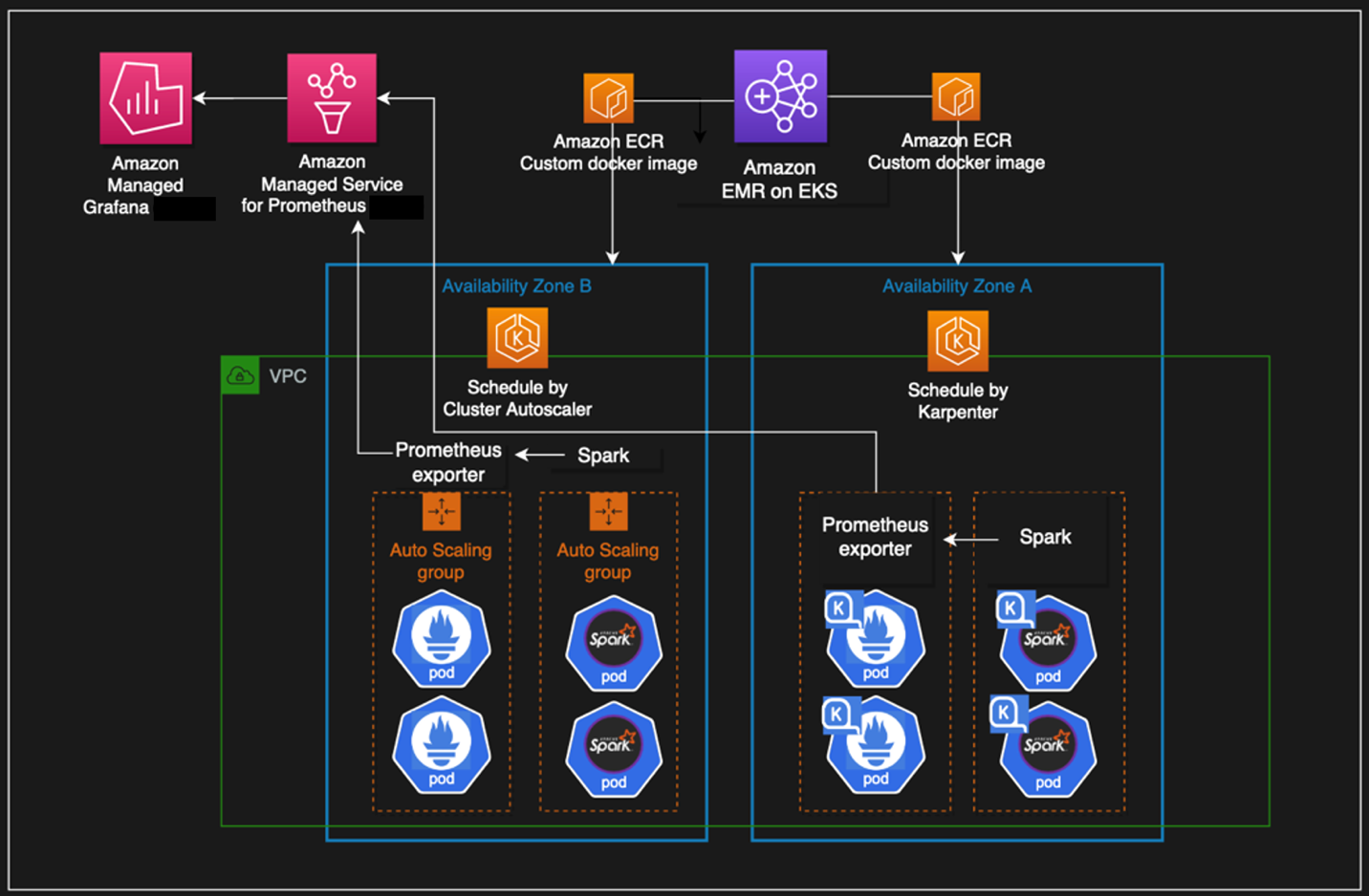
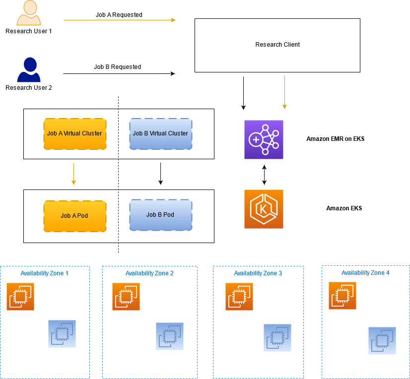
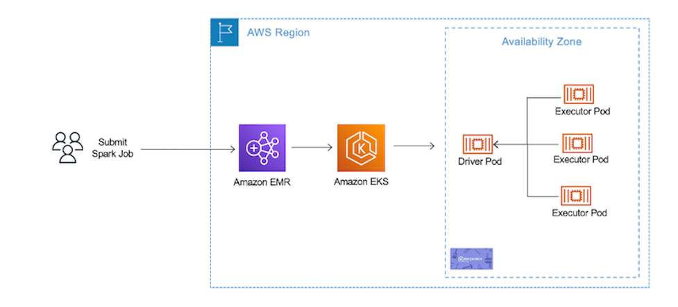
In this post, we show how a data engineer or IT administrator can use the AWS Analytics Reference Architecture (ARA) to accelerate infrastructure deployment, saving your organization both time and money spent on these data analytics experiments. We use the library to deploy an Amazon Elastic Kubernetes (Amazon EKS) cluster, configure it to use Amazon EMR on EKS, and deploy a virtual cluster and managed endpoints and EMR Studio. You can then either run jobs on the virtual cluster or run exploratory data analysis with Jupyter notebooks on Amazon EMR Studio and Amazon EMR on EKS. The architecture below represent the infrastructure you will deploy with the AWS Analytics Reference Architecture.

cdk-emr-eks-studio-architecture

Prerequisites

To follow along, you need to have an AWS account that is bootstrapped with the AWS Cloud Development Kit (AWS CDK). For instructions, refer to Bootstrapping. The following tutorial uses TypeScript, and requires version 2 or later of the AWS CDK. If you don’t have the AWS CDK installed, refer to Install the AWS CDK.

Set up an AWS CDK project

To deploy resources using the ARA, you first need to set up an AWS CDK project and install the ARA library. Complete the following steps:

  1. Create a folder named emr-eks-app:
    mkdir emr-eks-app && cd emr-eks-app

  2. Initialize an AWS CDK project in an empty directory and run the following command:
    cdk init app --language typescript

  3. Install the ARA library:
    npm install aws-analytics-reference-architecture --save

  4. In lib/emr-eks-app.ts, import the ARA library as follows. The first line calls the ARA library, the second one defines AWS Identity and Access Management (IAM) policies:
    import * as ara from 'aws-analytics-reference-architecture'; 
    import * as iam from 'aws-cdk-lib/aws-iam';

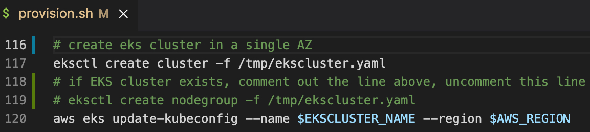
Create and define an EKS cluster and compute capacity

To create an EMR on EKS virtual cluster, you first need to deploy an EKS cluster. The ARA library defines a construct called EmrEksCluster. The construct provisions an EKS cluster, enables IAM roles for service accounts, and deploys a set of supporting controllers like certificate manager controller (needed by the managed endpoint that is used by Amazon EMR Studio) as well as a cluster auto scaler to have an elastic cluster and save on cost when no job is submitted to the cluster.

In lib/emr-eks-app.ts, add the following line:

const emrEks = ara.EmrEksCluster.getOrCreate(this,{ 
   eksAdminRoleArn:ROLE_ARN;, 
   eksClusterName:CLUSTER_NAME;
   autoscaling: Autoscaler.KARPENTER, 
});

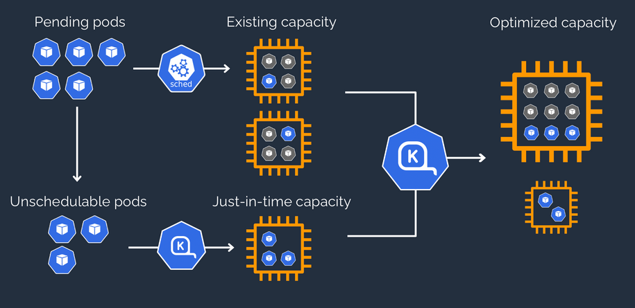
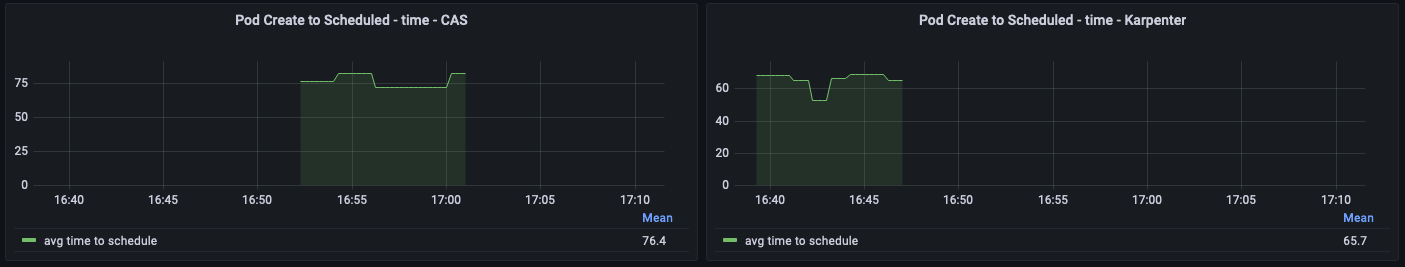
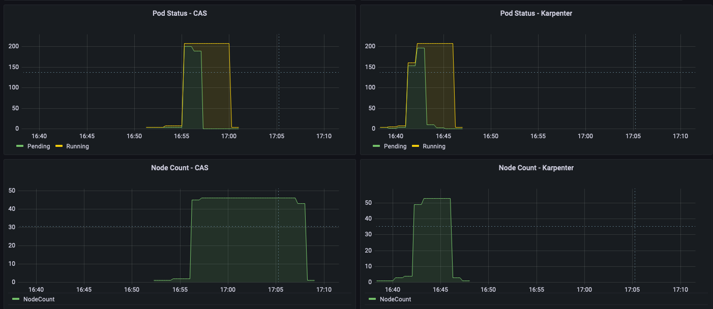
To learn more about the properties you can customize, refer to EmrEksClusterProps. There are two mandatory parameters in EmrEksCluster construct: The first is eksAdminRoleArn role is mandatory and is the role you use to interact with the Kubernetes control plane. This role must have administrative permissions to create or update the cluster. The second parameter is autoscaling, this parameter allows you to select the autoscaling mechanism, either Karpenter or native Kubernetes Cluster Autoscaler. In this blog we will use Karpenter and we recommend its use due to faster autoscaling, simplified node management and provisioning. Now you’re ready to define the compute capacity.

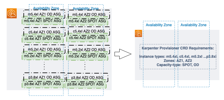
One way to define worker nodes in Amazon EKS is to use managed node groups. We use one node group called tooling, which hosts the coredns, ingress controller, certificate manager, Karpenter and any other pod that is necessary for the running EMR on EKS jobs or ManagedEndpoint. We also define default Karpenter Provisioners that define capacity to be used for jobs submitted by EMR on EKS. These Provisioners are optimized for different Spark use cases (critical jobs, non-critical job, experimentation and interactive sessions). The construct also allows you to submit your own provisioner defined by a Kubernetes manifest through a method called addKarpenterProvisioner. Let’s discuss the predefined Provisioners.

Default Provisioners configurations

The default provisioners are set for rapid experimentation and are always created by default. However, if you don’t want to use them, you can set the defaultNodeGroups parameter to false in the EmrEksCluster properties at creation time. The Provisioners are defined as follows and are created in each of the subnets that are used by Amazon EKS:

  • Critical provisioner – It is dedicated to supporting jobs with aggressive SLAs and are time sensitive. The provisioner uses On-Demand Instances, which aren’t stopped, unlike Spot Instances, and their lifecycle follows through one of the jobs. The nodes use instance stores, which are NVMe disks physically attached to the host, which offer a high I/O throughput that allow better Spark performance, because it’s used as temporary storage for disk spill and shuffle. The instance types used in the node are of the m6gd family. The instances use the AWS Graviton processor, which offers better price/performance than x86 processors. To use this provisioner in your jobs, you can use the following sample configuration, which is referenced in the configuration override of the EMR on EKS job submission.
  • Non-critical provisioner – This Provisioner leverage Spot Instances to save costs for jobs that aren’t time sensitive or jobs that are used for experiments. This node use Spot Instances because the jobs aren’t critical and can be interrupted. These instances can be stopped if the instance is reclaimed. The instance types used in the node are of the m6gd family, the driver is On-Demand and executors are on spot instances.
  • Notebook provisioner – The Provisioner is for running managed endpoints that are used by Amazon EMR Studio for data exploration using Amazon EMR on EKS. The instances are of t3 family and are On-Demand for driver and Spot Instances for executors to keep the cost low. If the executor instances are stopped, new ones are started by Karpenter. If the executor instances are stopped too often, you can define your own that use On-Demand instances.

The following link provides more details about how each of the provisioner are defined. One import property that is defined in the default Provisioners is there is one for each AZ. This is important because it allows you to reduce inter-AZ network transfer cost when Spark runs a shuffle.

For this post, we use the default Provisioners, so you don’t need to add any lines of code for this section. If you want yo add your own Provisioners you can leverage the method addKarpenterProvisioner to apply your own manifests. You can use helper methods in Utils class like readYamlDocument to read YAML document and loadYaml load YAML files and pass them as arguments to addKarpenterProvisioner method.

Deploy the virtual cluster and an execution role

A virtual cluster is a Kubernetes namespace that Amazon EMR is registered with; when you submit a job, the driver and executor pods are running in the associated namespace. The EmrEksCluster construct offers a method called addEmrVirtualCluster, which creates the virtual cluster for you. The method takes EmrVirtualClusterOptions as a parameter, which has the following attributes:

  • name – The name of your virtual cluster.
  • createNamespace – An optional field that creates the EKS namespace. This is of type Boolean and by default it doesn’t create a separate EKS namespace, so your virtual cluster is created in the default namespace.
  • eksNamespace – The name of the EKS namespace to be linked with the virtual EMR cluster. If no namespace is supplied, the construct uses the default namespace.
  1. In lib/emr-eks-app.ts, add the following line to create your virtual cluster:
    const virtualCluster = emrEks.addEmrVirtualCluster(this,{ 
       name:'my-emr-eks-cluster', 
       eksNamespace: ‘batchjob’, 
       createNamespace: true 
    });

    Now we create the execution role, which is an IAM role that is used by the driver and executor to interact with AWS services. Before we can create the execution role for Amazon EMR, we need to first create the ManagedPolicy. Note that in the following code, we create a policy to allow access to the Amazon Simple Storage Service (Amazon S3) bucket and Amazon CloudWatch logs.

  2. In lib/emr-eks-app.ts, add the following line to create the policy:
    const emrEksPolicy = new iam.ManagedPolicy(this,'managed-policy',
    { statements: [ 
       new iam.PolicyStatement({ 
           effect: iam.Effect.ALLOW, 
           actions:['s3:PutObject','s3:GetObject','s3:ListBucket'], 
           resources:['YOUR-DATA-S3-BUCKET']
        }), 
       new iam.PolicyStatement({ 
           effect: iam.Effect.ALLOW, 
           actions:['logs:PutLogEvents','logs:CreateLogStream','logs:DescribeLogGroups','logs:DescribeLogStreams'], 
           resources:['arn:aws:logs:*:*:*'] 
        })
       ] 
    });

    If you want to use the AWS Glue Data Catalog, add its permission in the preceding policy.

    Now we create the execution role for Amazon EMR on EKS using the policy defined in the previous step using the createExecutionRole instance method. The driver and executor pods can then assume this role to access and process data. The role is scoped in such a way that only pods in the virtual cluster namespace can assume it. To learn more about the condition implemented by this method to restrict access to the role to only pods that are created by Amazon EMR on EKS in the namespace of the virtual cluster, refer to Using job execution roles with Amazon EMR on EKS.

  3. In lib/emr-eks-app.ts, add the following line to create the execution role:
    const role = emrEks.createExecutionRole(this,'emr-eks-execution-role', emrEksPolicy, ‘batchjob’,’ execRoleJob’);

    The preceding code produces an IAM role called execRoleJob with the IAM policy defined in emrekspolicy and scoped to the namespace dataanalysis.

  4. Lastly, we output parameters that are important for the job run:
// Virtual cluster Id to reference in jobs
new cdk.CfnOutput(this, 'VirtualClusterId', { value: virtualCluster.attrId });

// Job config for each nodegroup
new cdk.CfnOutput(this, 'CriticalConfig', { value: emrEks.criticalDefaultConfig });

// Execution role arn
new cdk.CfnOutput(this, 'ExecRoleArn', { value: role.roleArn });

Deploy Amazon EMR Studio and provision users

To deploy an EMR Studio for data exploration and job authoring, the ARA library has a construct called NotebookPlatform. This construct allows you to deploy as many EMR Studios as you need (within the account limit) and set them up with the authentication mode that is suitable for you and assign users to them. To learn more about the authentication modes available in Amazon EMR Studio, refer to Choose an authentication mode for Amazon EMR Studio.

The construct creates all the necessary IAM roles and policies needed by Amazon EMR Studio. It also creates an S3 bucket where all the notebooks are stored by Amazon EMR Studio. The bucket is encrypted with a customer managed key (CMK) generated by the AWS CDK stack. The following steps show you how to create your own EMR Studio with the construct.

The notebook platform construct takes NotebookPlatformProps as a property, which allows you to define your EMR Studio, a namespace, the name of the EMR Studio, and its authentication mode.

  1. In lib/emr-eks-app.ts, add the following line:
    const notebookPlatform = new ara.NotebookPlatform(this, 'platform-notebook', {
    emrEks: emrEks,
    eksNamespace: 'dataanalysis',
    studioName: 'platform',
    studioAuthMode: ara.StudioAuthMode.IAM,
    });

    For this post, we use IAM users so that you can easily reproduce it in your own account. However, if you have IAM federation or single sign-on (SSO) already in place, you can use them instead of IAM users.To learn more about the parameters of NotebookPlatformProps, refer to NotebookPlatformProps.

    Next, we need to create and assign users to the Amazon EMR Studio. For this, the construct has a method called addUser that takes a list of users and either assigns them to Amazon EMR Studio in case of SSO or updates the IAM policy to allows access to Amazon EMR Studio for the provided IAM users. The user can also have multiple managed endpoints, and each user can have their Amazon EMR version defined. They can use a different set of Amazon Elastic Compute Cloud (Amazon EC2) instances and different permissions using job execution roles.

  2. In lib/emr-eks-app.ts, add the following line:
    notebookPlatform.addUser([{
    identityName:<NAME-OF-EXISTING-IAM-USER>,
    notebookManagedEndpoints: [{
    emrOnEksVersion: 'emr-6.8.0-latest',
    executionPolicy: emrEksPolicy,
    managedEndpointName: ‘myendpoint’
    }],
    }]);

    In the preceding code, for the sake of brevity, we reuse the same IAM policy that we created in the execution role.

    Note that the construct optimizes the number of managed endpoints that are created. If two endpoints have the same name, then only one is created.

  3. Now that we have defined our deployment, we can deploy it:
   npm run build && cdk deploy

You can find a sample project that contains all the steps of the walk through in the following GitHub repository.

When the deployment is complete, the output contains the S3 bucket containing the assets for podTemplate, the link for the EMR Studio, and the EMR Studio virtual cluster ID. The following screenshot shows the output of the AWS CDK after the deployment is complete.

CDK output
Submit jobs

Because we’re using the default Provisioners, we will use the podTemplate that is defined by the construct available on the ARA GitHub repository. These are uploaded for you by the construct to an S3 bucket called <clustername>-emr-eks-assets; you only need to refer to them in your Spark job. In this job, you also use the job parameters in the output at the end of the AWS CDK deployment. These parameters allow you to use the AWS Glue Data Catalog and implement Spark on Kubernetes best practices like dynamicAllocation and pod collocation. At the end of cdk deploy ARA will output job sample configurations with the best practices listed before that you can use to submit a job. You can submit a job as follows.

A job run is a unit of work such as a Spark JAR file that is submitted to the EMR on EKS cluster. We start a job using the start-job-run command. Note you can use SparkSubmitParameters to specify the Amazon S3 path to the pod template, as shown in the following command:

aws emr-containers start-job-run \

--virtual-cluster-id <CLUSTER-ID>\

--name <SPARK-JOB-NAME>\

--execution-role-arn <ROLE-ARN> \

--release-label emr-6.8.0-latest \

--job-driver '{
"sparkSubmitJobDriver": {
"entryPoint": ""<S3URI-SPARK-JOB>"
}
}' --configuration-overrides '{
"applicationConfiguration": [
{
"classification": "spark-defaults",
"properties": {
"spark.hadoop.hive.metastore.client.factory.class": "com.amazonaws.glue.catalog.metastore.AWSGlueDataCatalogHiveClientFactory",

"spark.sql.catalogImplementation": "hive",

"spark.dynamicAllocation.enabled":"true",

"spark.dynamicAllocation.minExecutors": "8",

"spark.dynamicAllocation.maxExecutors": "40",

"spark.kubernetes.allocation.batch.size": "8",

"spark.executor.cores": "8",

"spark.kubernetes.executor.request.cores": "7",

"spark.executor.memory": "28G",

"spark.driver.cores": "2",

"spark.kubernetes.driver.request.cores": "2",

"spark.driver.memory": "6G",

"spark.dynamicAllocation.executorAllocationRatio": "1",

"spark.dynamicAllocation.shuffleTracking.enabled": "true",

"spark.dynamicAllocation.shuffleTracking.timeout": "300s",

"spark.kubernetes.driver.podTemplateFile": s3://<EKS-CLUSTER-NAME>-emr-eks-assets-<ACCOUNT-ID>-<REGION> /<EKS-CLUSTER-NAME>/pod-template/critical-driver.yaml ",

"spark.kubernetes.executor.podTemplateFile": s3://<EKS-CLUSTER-NAME>-emr-eks-assets-<ACCOUNT-ID>-<REGION> /<EKS-CLUSTER-NAME>/pod-template/critical-executor.yaml "
}
}
],
"monitoringConfiguration": {
"cloudWatchMonitoringConfiguration": {
"logGroupName": ""<Log_Group_Name>",
"logStreamNamePrefix": "<Log_Stream_Prefix>"
}
}'

The code takes the following values:

  • <CLUSTER-ID> – The EMR virtual cluster ID
  • <SPARK-JOB-NAME> – The name of your Spark job
  • <ROLE-ARN> – The execution role you created
  • <S3URI-SPARK-JOB> – The Amazon S3 URI of your Spark job
  • <S3URI-CRITICAL-DRIVER> – The Amazon S3 URI of the driver pod template, which you get from the AWS CDK output
  • <S3URI-CRITICAL-EXECUTOR> – The Amazon S3 URI of the executor pod template
  • <Log_Group_Name> – Your CloudWatch log group name
  • <Log_Stream_Prefix> – Your CloudWatch log stream prefix

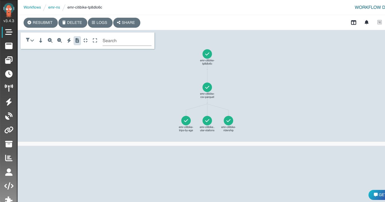
You can go to the Amazon EMR console to check the status of your job and to view logs. You can also check the status by running the describe-job-run command:

aws emr-containers describe-job-run --<CLUSTER-ID> cluster-id --id <JOB-RUN-ID>

Explore data using Amazon EMR Studio

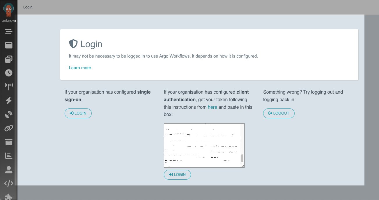
In this section, we show how you can create a workspace in Amazon EMR Studio and connect to the Amazon EKS managed endpoint from the workspace. From the output, use the link to Amazon EMR Studio to navigate to the EMR Studio deployment. You must sign in with the IAM username you provided in the addUser method.

Create a Workspace

To create a Workspace, complete the following steps:

  1. Log in to the EMR Studio created by the AWS CDK.
  2. Choose Create Workspace.
  3. Enter a workspace name and an optional description.
  4. Select Allow Workspace Collaboration if you want to work with other Studio users in this Workspace in real time.
  5. Choose Create Workspace.

create-emr-studio-workspace

After you create the Workspace, choose it from the list of Workspaces to open the JupyterLab environment.
emr studio workspace running

The following screenshot shows what the terminal looks like. For more information about the user interface, refer to Understand the Workspace user interface.

EMR Studio workspace view

Connect to an EMR on EKS managed endpoint

You can easily connect to the EMR on EKS managed endpoint from the Workspace.

  1. In the navigation pane, on the Clusters menu, select EMR Cluster on EKS for Cluster type.
    The virtual clusters appear on the EMR Cluster on EKS drop-down menu, and the endpoint appears on the Endpoint drop-down menu. If there are multiple endpoints, they appear here, and you can easily switch between endpoints from the Workspace.
  2. Select the appropriate endpoint and choose Attach.
    attach to managedendpoint

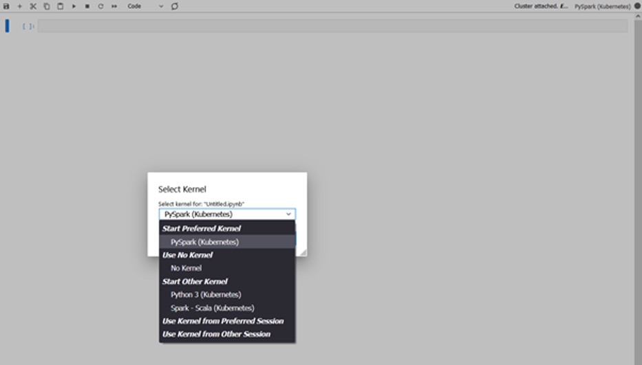
Work with a notebook

You can now open a notebook and connect to a preferred kernel to do your tasks. For instance, you can select a PySpark kernel, as shown in the following screenshot.
select-kernel

Explore your data

The first step of our data exploration exercise is to create a Spark session and then load the New York taxi dataset from the S3 bucket into a data frame. Use the following code block to load the data into a data frame. Copy the Amazon S3 URI for the location where the dataset resides in Amazon S3.

	from pyspark.sql import SparkSession
	from pyspark.sql.functions import *
	from datetime import datetime
	spark = SparkSession.builder.appName("SparkEDAA").getOrCreate()

After we load the data into a data frame, we replace the data of the current_date column with the actual current date, count the number of rows, and save the data into a Parquet file:

print("Total number of records: " + str(updatedNYTaxi.count()))
updatedNYTaxi.write.parquet("<YOUR-S3-PATH>")

The following screenshot shows the result of our notebook running on Amazon EMR Studio and with PySpark running on Amazon EMR on EKS.
notebook execution

Clean up

To clean up after this post, run cdk destroy.

Conclusion

In this post, we showed how you can use the ARA to quickly deploy a data analytics infrastructure and start experimenting with your data. You can find the full example referenced in this post in the GitHub repository. The AWS Analytics Reference Architecture implements common Analytics pattern and AWS best practices to offer you ready to use constructs to for your experiments. One of the patterns is the data mesh, which you can consult how to use in this blog post.

You can also explore other constructs offered in this library to experiment with AWS Analytics services before transitioning your workload for production.


About the Authors

co-author-1Lotfi Mouhib is a Senior Solutions Architect working for the Public Sector team with Amazon Web Services. He helps public sector customers across EMEA realize their ideas, build new services, and innovate for citizens. In his spare time, Lotfi enjoys cycling and running.

Sandipan Bhaumik is a Senior Analytics Specialist Solutions Architect based in London. He has worked with customers in different industries like Banking & Financial Services, Healthcare, Power & Utilities, Manufacturing and Retail helping them solve complex challenges with large-scale data platforms. At AWS he focuses on strategic accounts in the UK and Ireland and helps customers to accelerate their journey to the cloud and innovate using AWS analytics and machine learning services. He loves playing badminton, and reading books.

Run fault tolerant and cost-optimized Spark clusters using Amazon EMR on EKS and Amazon EC2 Spot Instances

Post Syndicated from Kinnar Kumar Sen original https://aws.amazon.com/blogs/big-data/run-fault-tolerant-and-cost-optimized-spark-clusters-using-amazon-emr-on-eks-and-amazon-ec2-spot-instances/

Amazon EMR on EKS is a deployment option in Amazon EMR that allows you to run Spark jobs on Amazon Elastic Kubernetes Service (Amazon EKS). Amazon Elastic Compute Cloud (Amazon EC2) Spot Instances save you up to 90% over On-Demand Instances, and is a great way to cost optimize the Spark workloads running on Amazon EMR on EKS. Because Spot is an interruptible service, if we can move or reuse the intermediate shuffle files, it improves the overall stability and SLA of the job. The latest versions of Amazon EMR on EKS have integrated Spark features to enable this capability.

In this post, we discuss these features—Node Decommissioning and Persistent Volume Claim (PVC) reuse—and their impact on increasing the fault tolerance of Spark jobs on Amazon EMR on EKS when cost optimizing using EC2 Spot Instances.

Amazon EMR on EKS and Spot

EC2 Spot Instances are spare EC2 capacity provided at a steep discount of up to 90% over On-Demand prices. Spot Instances are a great choice for stateless and flexible workloads. The caveat with this discount and spare capacity is that Amazon EC2 can interrupt an instance with a proactive or reactive (2-minute) warning when it needs the capacity back. You can provision compute capacity in an EKS cluster using Spot Instances using a managed or self-managed node group and provide cost optimization for your workloads.

Amazon EMR on EKS uses Amazon EKS to run jobs with the EMR runtime for Apache Spark, which can be cost optimized by running the Spark executors on Spot. It provides up to 61% lower costs and up to 68% performance improvement for Spark workloads on Amazon EKS. The Spark application launches a driver and executors to run the computation. Spark is a semi-fault tolerant framework that is resilient to executor loss due to an interruption and therefore can run on EC2 Spot. On the other hand, when the driver is interrupted, the job fails. Hence, we recommend running drivers on on-demand instances. Some of the best practices for running Spark on Amazon EKS are applicable with Amazon EMR on EKS.

EC2 Spot instances also helps in cost optimization by improving the overall throughput of the job. This can be achieved by auto-scaling the cluster using Cluster Autoscaler (for managed nodegroups) or Karpenter.

Though Spark executors are resilient to Spot interruptions, the shuffle files and RDD data is lost when the executor gets killed. The lost shuffle files need to be recomputed, which increases the overall runtime of the job. Apache Spark has released two features (in versions 3.1 and 3.2) that addresses this issue. Amazon EMR on EKS released features such as node decommissioning (version 6.3) and PVC reuse (version 6.8) to simplify recovery and reuse shuffle files, which increases the overall resiliency of your application.

Node decommissioning

The node decommissioning feature works by preventing scheduling of new jobs on the nodes that are to be decommissioned. It also moves any shuffle files or cache present in those nodes to other executors (peers). If there are no other available executors, the shuffle files and cache are moved to a remote fallback storage.

Node Decommissioning

Fig 1 : Node Decommissioning

Let’s look at the decommission steps in more detail.

If one of the nodes that is running executors is interrupted, the executor starts the process of decommissioning and sends the message to the driver:

21/05/05 17:41:41 WARN KubernetesClusterSchedulerBackend$KubernetesDriverEndpoint: Received executor 7 decommissioned message
21/05/05 17:41:41 DEBUG TaskSetManager: Valid locality levels for TaskSet 2.0: NO_PREF, ANY
21/05/05 17:41:41 INFO KubernetesClusterSchedulerBackend: Decommission executors: 7
21/05/05 17:41:41 DEBUG TaskSchedulerImpl: parentName: , name: TaskSet_2.0, runningTasks: 10
21/05/05 17:41:41 INFO BlockManagerMasterEndpoint: Mark BlockManagers (BlockManagerId(7, 192.168.82.107, 39007, None)) as being decommissioning.
21/05/05 20:22:17 INFO CoarseGrainedExecutorBackend: Decommission executor 1.
21/05/05 20:22:17 INFO CoarseGrainedExecutorBackend: Will exit when finished decommissioning
21/05/05 20:22:17 INFO BlockManager: Starting block manager decommissioning process...
21/05/05 20:22:17 DEBUG FileSystem: Looking for FS supporting s3a

The executor looks for RDD or shuffle files and tries to replicate or migrate those files. It first tries to find a peer executor. If successful, it will move the files to the peer executor:

22/06/07 20:41:38 INFO ShuffleStatus: Updating map output for 46 to BlockManagerId(4, 192.168.13.235, 34737, None)
22/06/07 20:41:38 DEBUG BlockManagerMasterEndpoint: Received shuffle data block update for 0 46, ignore.
22/06/07 20:41:38 DEBUG BlockManagerMasterEndpoint: Received shuffle index block update for 0 46, updating.

However, if It is not able to find a peer executor, it will try to move the files to a fallback storage if available.

Fallback Storage

Fig 2: Fallback Storage

The executor is then decommissioned. When a new executor comes up, the shuffle files are reused:

22/06/07 20:42:50 INFO BasicExecutorFeatureStep: Adding decommission script to lifecycle
22/06/07 20:42:50 DEBUG ExecutorPodsAllocator: Requested executor with id 19 from Kubernetes.
22/06/07 20:42:50 DEBUG ExecutorPodsWatchSnapshotSource: Received executor pod update for pod named amazon-reviews-word-count-bfd0a5813fd1b80f-exec-19, action ADDED
22/06/07 20:42:50 DEBUG BlockManagerMasterEndpoint: Received shuffle index block update for 0 52, updating.
22/06/07 20:42:50 INFO ShuffleStatus: Recover 52 BlockManagerId(fallback, remote, 7337, None)

The key advantage of this process is that it enables migrates blocks and shuffle data, thereby reducing recomputation, which adds to the overall resiliency of the system and reduces runtime. This process can be triggered by a Spot interruption signal (Sigterm) and node draining. Node draining  may happen due to high-priority task scheduling or independently.

When you use Amazon EMR on EKS with managed node groups/Karpenter, the Spot interruption handling is automated, wherein Amazon EKS gracefully drains and rebalances the Spot nodes to minimize application disruption when a Spot node is at elevated risk of interruption. If you’re using managed node groups/Karpenter, the decommission gets triggered when the nodes are getting drained and because it’s proactive, it gives you more time (at least 2 minutes) to move the files. In the case of self-managed node groups, we recommend installing the AWS Node Termination Handler to handle the interruption, and the decommission is triggered when the reactive (2-minute) notification is received. We recommend to use Karpenter with Spot Instances as it has faster node scheduling with early pod binding and binpacking to optimize the resource utilization.

The following code enables this configuration; more details are available on GitHub:

"spark.decommission.enabled": "true"
"spark.storage.decommission.rddBlocks.enabled": "true"
"spark.storage.decommission.shuffleBlocks.enabled" : "true"
"spark.storage.decommission.enabled": "true"
"spark.storage.decommission.fallbackStorage.path": "s3://<<bucket>>"

PVC reuse

Apache Spark enabled dynamic PVC in version 3.1, which is useful with dynamic allocation because we don’t have to pre-create the claims or volumes for the executors and delete them after completion. PVC enables true decoupling of data and processing when we’re running Spark jobs on Kubernetes, because we can use it as a local storage to spill in-process files too. The latest version of Amazon EMR 6.8 has integrated the PVC reuse feature of Spark, wherein if an executor is terminated due to EC2 Spot interruption or any other reason (JVM), then the PVC is not deleted but persisted and reattached to another executor. If there are shuffle files in that volume, then they are reused.

As with node decommission, this reduces the overall runtime because we don’t have to recompute the shuffle files. We also save the time required to request a new volume for an executor, and shuffle files can be reused without moving the files round.

The following diagram illustrates this workflow.

PVC Reuse

Fig 3: PVC Reuse

Let’s look at the steps in more detail.

If one or more of the nodes that are running executors is interrupted, the underlying pods get terminated and the driver gets the update. Note that the driver is the owner of the PVC of the executors, and they are not terminated. See the following code:

22/06/15 23:25:07 DEBUG ExecutorPodsWatchSnapshotSource: Received executor pod update for pod named amazon-reviews-word-count-9ee82b8169a75183-exec-3, action DELETED
22/06/15 23:25:07 DEBUG ExecutorPodsWatchSnapshotSource: Received executor pod update for pod named amazon-reviews-word-count-9ee82b8169a75183-exec-6, action MODIFIED
22/06/15 23:25:07 DEBUG ExecutorPodsWatchSnapshotSource: Received executor pod update for pod named amazon-reviews-word-count-9ee82b8169a75183-exec-6, action DELETED
22/06/15 23:25:07 DEBUG ExecutorPodsWatchSnapshotSource: Received executor pod update for pod named amazon-reviews-word-count-9ee82b8169a75183-exec-3, action MODIFIED

The ExecutorPodsAllocator tries to allocate new executor pods to replace the ones terminated due to interruption. During the allocation, it figures out how many of the existing PVCs have files and can be reused:

22/06/15 23:25:23 INFO ExecutorPodsAllocator: Found 2 reusable PVCs from 10 PVCs

The ExecutorPodsAllocator requests for a pod and when it launches it, the PVC is reused. In the following example, the PVC from executor 6 is reused for new executor pod 11:

22/06/15 23:25:23 DEBUG ExecutorPodsAllocator: Requested executor with id 11 from Kubernetes.
22/06/15 23:25:24 DEBUG ExecutorPodsWatchSnapshotSource: Received executor pod update for pod named amazon-reviews-word-count-9ee82b8169a75183-exec-11, action ADDED
22/06/15 23:25:24 INFO KubernetesClientUtils: Spark configuration files loaded from Some(/usr/lib/spark/conf) : log4j.properties,spark-env.sh,hive-site.xml,metrics.properties
22/06/15 23:25:24 INFO BasicExecutorFeatureStep: Decommissioning not enabled, skipping shutdown script
22/06/15 23:25:24 DEBUG ExecutorPodsWatchSnapshotSource: Received executor pod update for pod named amazon-reviews-word-count-9ee82b8169a75183-exec-11, action MODIFIED
22/06/15 23:25:24 INFO ExecutorPodsAllocator: Reuse PersistentVolumeClaim amazon-reviews-word-count-9ee82b8169a75183-exec-6-pvc-0

The shuffle files, if present in the PVC are reused.

The key advantage of this technique is that it allows us to reuse pre-computed shuffle files in their original location, thereby reducing the time of the overall job run.

This works for both static and dynamic PVCs. Amazon EKS offers three different storage offerings, which can be encrypted too: Amazon Elastic Block Store (Amazon EBS), Amazon Elastic File System (Amazon EFS), and Amazon FSx for Lustre. We recommend using dynamic PVCs with Amazon EBS because with static PVCs, you would need to create multiple PVCs.

The following code enables this configuration; more details are available on GitHub:

"spark.kubernetes.driver.ownPersistentVolumeClaim": "true"
"spark.kubernetes.driver.reusePersistentVolumeClaim": "true"

For this to work, we need to enable PVC with Amazon EKS and mention the details in the Spark runtime configuration. For instructions, refer to How do I use persistent storage in Amazon EKS? The following code contains the Spark configuration details for using PVC as local storage; other details are available on GitHub:

"spark.kubernetes.executor.volumes.persistentVolumeClaim.spark-local-dir-1.mount.readOnly": "false"
"spark.kubernetes.executor.volumes.persistentVolumeClaim.spark-local-dir-1.options.claimName": "OnDemand"
"spark.kubernetes.executor.volumes.persistentVolumeClaim.spark-local-dir-1.options.storageClass": "spark-sc"
"spark.kubernetes.executor.volumes.persistentVolumeClaim.spark-local-dir-1.options.sizeLimit": "10Gi"
"spark.kubernetes.executor.volumes.persistentVolumeClaim.spark-local-dir-1.mount.path": "/var/data/spill"

Conclusion

With Amazon EMR on EKS (6.9) and the features discussed in this post, you can further reduce the overall runtime for Spark jobs when running with Spot Instances. This also improves the overall resiliency and flexibility of the job while cost optimizing the workload on EC2 Spot.

Try out the EMR on EKS workshop for improved performance when running Spark workloads on Kubernetes and cost optimize using EC2 Spot Instances.


About the Author

Kinnar Kumar Sen is a Sr. Solutions Architect at Amazon Web Services (AWS) focusing on Flexible Compute. As a part of the EC2 Flexible Compute team, he works with customers to guide them to the most elastic and efficient compute options that are suitable for their workload running on AWS. Kinnar has more than 15 years of industry experience working in research, consultancy, engineering, and architecture.

Introducing ACK controller for Amazon EMR on EKS

Post Syndicated from Peter Dalbhanjan original https://aws.amazon.com/blogs/big-data/introducing-ack-controller-for-amazon-emr-on-eks/

AWS Controllers for Kubernetes (ACK) was announced in August, 2020, and now supports 14 AWS service controllers as generally available with an additional 12 in preview. The vision behind this initiative was simple: allow Kubernetes users to use the Kubernetes API to manage the lifecycle of AWS resources such as Amazon Simple Storage Service (Amazon S3) buckets or Amazon Relational Database Service (Amazon RDS) DB instances. For example, you can define an S3 bucket as a custom resource, create this bucket as part of your application deployment, and delete it when your application is retired.

Amazon EMR on EKS is a deployment option for EMR that allows organizations to run Apache Spark on Amazon Elastic Kubernetes Service (Amazon EKS) clusters. With EMR on EKS, the Spark jobs run using the Amazon EMR runtime for Apache Spark. This increases the performance of your Spark jobs so that they run faster and cost less than open source Apache Spark. Also, you can run Amazon EMR-based Apache Spark applications with other types of applications on the same EKS cluster to improve resource utilization and simplify infrastructure management.

Today, we’re excited to announce the ACK controller for Amazon EMR on EKS is generally available. Customers have told us that they like the declarative way of managing Apache Spark applications on EKS clusters. With the ACK controller for EMR on EKS, you can now define and run Amazon EMR jobs directly using the Kubernetes API. This lets you manage EMR on EKS resources directly using Kubernetes-native tools such as kubectl.

The controller pattern has been widely adopted by the Kubernetes community to manage the lifecycle of resources. In fact, Kubernetes has built-in controllers for built-in resources like Jobs or Deployment. These controllers continuously ensure that the observed state of a resource matches the desired state of the resource stored in Kubernetes. For example, if you define a deployment that has NGINX using three replicas, the deployment controller continuously watches and tries to maintain three replicas of NGINX pods. Using the same pattern, the ACK controller for EMR on EKS installs two custom resource definitions (CRDs): VirtualCluster and JobRun. When you create EMR virtual clusters, the controller tracks these as Kubernetes custom resources and calls the EMR on EKS service API (also known as emr-containers) to create and manage these resources. If you want to get a deeper understanding of how ACK works with AWS service APIs, and learn how ACK generates Kubernetes resources like CRDs, see blog post.

If you need a simple getting started tutorial, refer to Run Spark jobs using the ACK EMR on EKS controller. Typically, customers who run Apache Spark jobs on EKS clusters use higher level abstraction such as Argo Workflows, Apache Airflow, or AWS Step Functions, and use workflow-based orchestration in order to run their extract, transform, and load (ETL) jobs. This gives you a consistent experience running jobs while defining job pipelines using Directed Acyclic Graphs (DAGs). DAGs allow you organize your job steps with dependencies and relationships to say how they should run. Argo Workflows is a container-native workflow engine for orchestrating parallel jobs on Kubernetes.

In this post, we show you how to use Argo Workflows with the ACK controller for EMR on EKS to run Apache Spark jobs on EKS clusters.

Solution overview

In the following diagram, we show Argo Workflows submitting a request to the Kubernetes API using its orchestration mechanism.

We’re using Argo to showcase the possibilities with workflow orchestration in this post, but you can also submit jobs directly using kubectl (the Kubernetes command line tool). When Argo Workflows submits these requests to the Kubernetes API, the ACK controller for EMR on EKS reconciles VirtualCluster custom resources by invoking the EMR on EKS APIs.

Let’s go through an exercise of creating custom resources using the ACK controller for EMR on EKS and Argo Workflows.

Prerequisites

Your environment needs the following tools installed:

Install the ACK controller for EMR on EKS

You can either create an EKS cluster or re-use an existing one. We refer to the instructions in Run Spark jobs using the ACK EMR on EKS controller to set up our environment. Complete the following steps:

  1. Install the EKS cluster.
  2. Create IAM Identity mapping.
  3. Install emrcontainers-controller.
  4. Configure IRSA for the EMR on EKS controller.
  5. Create an EMR job execution role and configure IRSA.

At this stage, you should have an EKS cluster with proper role-based access control (RBAC) permissions so that Amazon EMR can run its jobs. You should also have the ACK controller for EMR on EKS installed and the EMR job execution role with IAM Roles for Service Account (IRSA) configurations so that they have the correct permissions to call EMR APIs.

Please note, we’re skipping the step to create an EMR virtual cluster because we want to create a custom resource using Argo Workflows. If you created this resource using the getting started tutorial, you can either delete the virtual cluster or create new IAM identity mapping using a different namespace.

Let’s validate the annotation for the EMR on EKS controller service account before proceeding:

# validate annotation
kubectl get pods -n $ACK_SYSTEM_NAMESPACE
CONTROLLER_POD_NAME=$(kubectl get pods -n $ACK_SYSTEM_NAMESPACE --selector=app.kubernetes.io/name=emrcontainers-chart -o jsonpath='{.items..metadata.name}')
kubectl describe pod -n $ACK_SYSTEM_NAMESPACE $CONTROLLER_POD_NAME | grep "^\s*AWS_"

The following code shows the expected results:

AWS_REGION:                      us-west-2
AWS_ENDPOINT_URL:
AWS_ROLE_ARN:                    arn:aws:iam::012345678910:role/ack-emrcontainers-controller
AWS_WEB_IDENTITY_TOKEN_FILE:     /var/run/secrets/eks.amazonaws.com/serviceaccount/token (http://eks.amazonaws.com/serviceaccount/token)

Check the logs of the controller:

kubectl logs ${CONTROLLER_POD_NAME} -n ${ACK_SYSTEM_NAMESPACE}

The following code is the expected outcome:

2022-11-02T18:52:33.588Z    INFO    controller.virtualcluster    Starting Controller    {"reconciler group": "emrcontainers.services.k8s.aws", "reconciler kind": "VirtualCluster"}
2022-11-02T18:52:33.588Z    INFO    controller.virtualcluster    Starting EventSource    {"reconciler group": "emrcontainers.services.k8s.aws", "reconciler kind": "VirtualCluster", "source": "kind source: *v1alpha1.VirtualCluster"}
2022-11-02T18:52:33.589Z    INFO    controller.virtualcluster    Starting Controller    {"reconciler group": "emrcontainers.services.k8s.aws", "reconciler kind": "VirtualCluster"}
2022-11-02T18:52:33.589Z    INFO    controller.jobrun    Starting EventSource    {"reconciler group": "emrcontainers.services.k8s.aws", "reconciler kind": "JobRun", "source": "kind source: *v1alpha1.JobRun"}
2022-11-02T18:52:33.589Z    INFO    controller.jobrun    Starting Controller    {"reconciler group": "emrcontainers.services.k8s.aws", "reconciler kind": "JobRun"}
...
2022-11-02T18:52:33.689Z    INFO    controller.jobrun    Starting workers    {"reconciler group": "emrcontainers.services.k8s.aws", "reconciler kind": "JobRun", "worker count": 1}
2022-11-02T18:52:33.689Z    INFO    controller.virtualcluster    Starting workers    {"reconciler group": "emrcontainers.services.k8s.aws", "reconciler kind": "VirtualCluster", "worker count": 1}

Now we’re ready to install Argo Workflows and use workflow orchestration to create EMR on EKS virtual clusters and submit jobs.

Install Argo Workflows

The following steps are meant for quick installation with a proof of concept in mind. This is not meant for a production install. We recommend reviewing the Argo documentation, security guidelines, and other considerations for a production install.

We install the argo CLI first. We have provided instructions to install the argo CLI using brew, which is compatible with the Mac operating system. If you use Linux or another OS, refer to Quick Start for installation steps.

brew install argo

Let’s create a namespace and install Argo Workflows on your EMR on EKS cluster:

kubectl create namespace argo
kubectl apply -n argo -f https://github.com/argoproj/argo-workflows/releases/download/v3.4.3/install.yaml

You can access the Argo UI locally by port-forwarding the argo-server deployment:

kubectl -n argo port-forward deploy/argo-server 2746:2746

You can access the web UI at https://localhost:2746. You will get a notice that “Your connection is not private” because Argo is using a self-signed certificate. It’s okay to choose Advanced and then Proceed to localhost.

Please note, you get an Access Denied error because we haven’t configured permissions yet. Let’s set up RBAC so that Argo Workflows has permissions to communicate with the Kubernetes API. We give admin permissions to argo serviceaccount in the argo and emr-ns namespaces.

Open another terminal window and run these commands:

# setup rbac 
kubectl create rolebinding default-admin --clusterrole=admin --serviceaccount=argo:default --namespace=argo
kubectl create rolebinding default-admin --clusterrole=admin --serviceaccount=argo:default --namespace=emr-ns

# extract bearer token to login into UI
SECRET=$(kubectl get sa default -n argo -o=jsonpath='{.secrets[0].name}')
ARGO_TOKEN="Bearer $(kubectl get secret $SECRET -n argo -o=jsonpath='{.data.token}' | base64 --decode)"
echo $ARGO_TOKEN

You now have a bearer token that we need to enter for client authentication.

You can now navigate to the Workflows tab and change the namespace to emr-ns to see the workflows under this namespace.

Let’s set up RBAC permissions and create a workflow that creates an EMR on EKS virtual cluster:

cat << EOF > argo-emrcontainers-vc-role.yaml
apiVersion: rbac.authorization.k8s.io/v1
kind: ClusterRole
metadata:
  name: argo-emrcontainers-virtualcluster
rules:
  - apiGroups:
      - emrcontainers.services.k8s.aws
    resources:
      - virtualclusters
    verbs:
      - '*'
EOF

cat << EOF > argo-emrcontainers-jr-role.yaml
apiVersion: rbac.authorization.k8s.io/v1
kind: ClusterRole
metadata:
  name: argo-emrcontainers-jobrun
rules:
  - apiGroups:
      - emrcontainers.services.k8s.aws
    resources:
      - jobruns
    verbs:
      - '*'
EOF

Let’s create these roles and a role binding:

# create argo clusterrole with permissions to emrcontainers.services.k8s.aws
kubectl apply -f argo-emrcontainers-vc-role.yaml
kubectl apply -f argo-emrcontainers-jr-role.yaml

# Give permissions for argo to use emr-containers clusterrole
kubectl create rolebinding argo-emrcontainers-virtualcluster --clusterrole=argo-emrcontainers-virtualcluster --serviceaccount=emr-ns:default -n emr-ns
kubectl create rolebinding argo-emrcontainers-jobrun --clusterrole=argo-emrcontainers-jobrun --serviceaccount=emr-ns:default -n emr-ns

Let’s recap what we have done so far. We created an EMR on EKS cluster, installed the ACK controller for EMR on EKS using Helm, installed the Argo CLI, installed Argo Workflows, gained access to the Argo UI, and set up RBAC permissions for Argo. RBAC permissions are required so that the default service account in the Argo namespace can use VirtualCluster and JobRun custom resources via the emrcontainers.services.k8s.aws API.

It’s time to create the EMR virtual cluster. The environment variables used in the following code are from the getting started guide, but you can change these to meet your environment:

export EKS_CLUSTER_NAME=ack-emr-eks
export EMR_NAMESPACE=emr-ns

cat << EOF > argo-emr-virtualcluster.yaml
apiVersion: argoproj.io/v1alpha1
kind: Workflow
metadata:
  name: emr-virtualcluster
spec:
  arguments: {}
  entrypoint: emr-virtualcluster
  templates:
  - name: emr-virtualcluster
    resource:
      action: create
      manifest: |
        apiVersion: emrcontainers.services.k8s.aws/v1alpha1
        kind: VirtualCluster
        metadata:
          name: my-ack-vc
        spec:
          name: my-ack-vc
          containerProvider:
            id: ${EKS_CLUSTER_NAME}
            type_: EKS
            info:
              eksInfo:
                namespace: ${EMR_NAMESPACE}
EOF

Use the following command to create an Argo Workflow for virtual cluster creation:

kubectl apply -f argo-emr-virtualcluster.yaml -n emr-ns
argo list -n emr-ns

The following code is the expected result from the Argo CLI:

NAME                 STATUS      AGE   DURATION   PRIORITY   MESSAGE
emr-virtualcluster   Succeeded   12m   11s        0 

Check the status of virtualcluster:

kubectl describe virtualcluster/my-ack-vc -n emr-ns

The following code is the expected result from the preceding command:

Name:         my-ack-vc
Namespace:    default
Labels:       <none>
Annotations:  <none>
API Version:  emrcontainers.services.k8s.aws/v1alpha1
Kind:         VirtualCluster
...
Status:
  Ack Resource Metadata:
    Arn:               arn:aws:emr-containers:us-west-2:012345678910:/virtualclusters/dxnqujbxexzri28ph1wspbxo0
    Owner Account ID:  012345678910
    Region:            us-west-2
  Conditions:
    Last Transition Time:  2022-11-03T15:34:10Z
    Message:               Resource synced successfully
    Reason:                
    Status:                True
    Type:                  ACK.ResourceSynced
  Id:                      dxnqujbxexzri28ph1wspbxo0
Events:                    <none>

If you run into issues, you can check Argo logs using the following command or through the console:

argo logs emr-virtualcluster -n emr-ns

You can also check controller logs as mentioned in the troubleshooting guide.

Because we have an EMR virtual cluster ready to accept jobs, we can start working on the prerequisites for job submission.

Create an S3 bucket and Amazon CloudWatch Logs group that are needed for the job (see the following code). If you already created these resources from the getting started tutorial, you can skip this step.

export RANDOM_ID1=$(LC_ALL=C tr -dc a-z0-9 </dev/urandom | head -c 8)

aws logs create-log-group --log-group-name=/emr-on-eks-logs/$EKS_CLUSTER_NAME
aws s3 mb s3://$EKS_CLUSTER_NAME-$RANDOM_ID1

We use the New York Citi Bike dataset, which has rider demographics and trip data information. Run the following command to copy the dataset into your S3 bucket:

export S3BUCKET=$EKS_CLUSTER_NAME-$RANDOM_ID1
aws s3 sync s3://tripdata/ s3://${S3BUCKET}/citibike/csv/

Copy the sample Spark application code to your S3 bucket:

aws s3 cp s3://aws-blogs-artifacts-public/artifacts/BDB-2782/citibike-convert-csv-to-parquet.py s3://${S3BUCKET}/application/
aws s3 cp s3://aws-blogs-artifacts-public/artifacts/BDB-2782/citibike-ridership.py s3://${S3BUCKET}/application/
aws s3 cp s3://aws-blogs-artifacts-public/artifacts/BDB-2782/citibike-popular-stations.py s3://${S3BUCKET}/application/
aws s3 cp s3://aws-blogs-artifacts-public/artifacts/BDB-2782/citibike-trips-by-age.py s3://${S3BUCKET}/application/

Now, it’s time to run sample Spark job. Run the following to generate an Argo workflow submission template:

export RANDOM_ID2=$(LC_ALL=C tr -dc a-z0-9 </dev/urandom | head -c 8)

cat << EOF > argo-citibike-steps-jobrun.yaml
apiVersion: argoproj.io/v1alpha1
kind: Workflow
metadata:
  name: emr-citibike-${RANDOM_ID2}
spec:
  entrypoint: emr-citibike
  templates:
  - name: emr-citibike
    steps:
    - - name: emr-citibike-csv-parquet
        template: emr-citibike-csv-parquet
    - - name: emr-citibike-ridership
        template: emr-citibike-ridership
      - name: emr-citibike-popular-stations
        template: emr-citibike-popular-stations
      - name: emr-citibike-trips-by-age
        template: emr-citibike-trips-by-age

  # This is parent job that converts csv data to parquet
  - name: emr-citibike-csv-parquet
    resource:
      action: create
      successCondition: status.state == COMPLETED
      failureCondition: status.state == FAILED      
      manifest: |
        apiVersion: emrcontainers.services.k8s.aws/v1alpha1
        kind: JobRun
        metadata:
          name: my-ack-jobrun-csv-parquet-${RANDOM_ID2}
        spec:
          name: my-ack-jobrun-csv-parquet-${RANDOM_ID2}
          virtualClusterRef:
            from:
              name: my-ack-vc
          executionRoleARN: "${ACK_JOB_EXECUTION_ROLE_ARN}"
          releaseLabel: "emr-6.7.0-latest"
          jobDriver:
            sparkSubmitJobDriver:
              entryPoint: "s3://${S3BUCKET}/application/citibike-convert-csv-to-parquet.py"
              entryPointArguments: [${S3BUCKET}]
              sparkSubmitParameters: "--conf spark.executor.instances=2 --conf spark.executor.memory=1G --conf spark.executor.cores=1 --conf spark.driver.cores=1 --conf spark.sql.shuffle.partitions=60 --conf spark.dynamicAllocation.enabled=false"
          configurationOverrides: |
            ApplicationConfiguration: null
            MonitoringConfiguration:
              CloudWatchMonitoringConfiguration:
                LogGroupName: /emr-on-eks-logs/${EKS_CLUSTER_NAME}
                LogStreamNamePrefix: citibike
              S3MonitoringConfiguration:
                LogUri: s3://${S3BUCKET}/logs

  # This is a child job which runs after csv-parquet jobs is complete
  - name: emr-citibike-ridership
    resource:
      action: create
      manifest: |
        apiVersion: emrcontainers.services.k8s.aws/v1alpha1
        kind: JobRun
        metadata:
          name: my-ack-jobrun-ridership-${RANDOM_ID2}
        spec:
          name: my-ack-jobrun-ridership-${RANDOM_ID2}
          virtualClusterRef:
            from:
              name: my-ack-vc
          executionRoleARN: "${ACK_JOB_EXECUTION_ROLE_ARN}"
          releaseLabel: "emr-6.7.0-latest"
          jobDriver:
            sparkSubmitJobDriver:
              entryPoint: "s3://${S3BUCKET}/application/citibike-ridership.py"
              entryPointArguments: [${S3BUCKET}]
              sparkSubmitParameters: "--conf spark.executor.instances=2 --conf spark.executor.memory=1G --conf spark.executor.cores=1 --conf spark.driver.cores=1 --conf spark.sql.shuffle.partitions=60 --conf spark.dynamicAllocation.enabled=false"
          configurationOverrides: |
            ApplicationConfiguration: null
            MonitoringConfiguration:
              CloudWatchMonitoringConfiguration:
                LogGroupName: /emr-on-eks-logs/${EKS_CLUSTER_NAME}
                LogStreamNamePrefix: citibike
              S3MonitoringConfiguration:
                LogUri: s3://${S3BUCKET}/logs   

  # This is a child job which runs after csv-parquet jobs is complete
  - name: emr-citibike-popular-stations
    resource:
      action: create
      manifest: |
        apiVersion: emrcontainers.services.k8s.aws/v1alpha1
        kind: JobRun
        metadata:
          name: my-ack-jobrun-popular-stations-${RANDOM_ID2}
        spec:
          name: my-ack-jobrun-popular-stations-${RANDOM_ID2}
          virtualClusterRef:
            from:
              name: my-ack-vc
          executionRoleARN: "${ACK_JOB_EXECUTION_ROLE_ARN}"
          releaseLabel: "emr-6.7.0-latest"
          jobDriver:
            sparkSubmitJobDriver:
              entryPoint: "s3://${S3BUCKET}/application/citibike-popular-stations.py"
              entryPointArguments: [${S3BUCKET}]
              sparkSubmitParameters: "--conf spark.executor.instances=2 --conf spark.executor.memory=1G --conf spark.executor.cores=1 --conf spark.driver.cores=1 --conf spark.sql.shuffle.partitions=60 --conf spark.dynamicAllocation.enabled=false"
          configurationOverrides: |
            ApplicationConfiguration: null
            MonitoringConfiguration:
              CloudWatchMonitoringConfiguration:
                LogGroupName: /emr-on-eks-logs/${EKS_CLUSTER_NAME}
                LogStreamNamePrefix: citibike
              S3MonitoringConfiguration:
                LogUri: s3://${S3BUCKET}/logs             

  # This is a child job which runs after csv-parquet jobs is complete
  - name: emr-citibike-trips-by-age
    resource:
      action: create
      manifest: |
        apiVersion: emrcontainers.services.k8s.aws/v1alpha1
        kind: JobRun
        metadata:
          name: my-ack-jobrun-trips-by-age-${RANDOM_ID2}
        spec:
          name: my-ack-jobrun-trips-by-age-${RANDOM_ID2}
          virtualClusterRef:
            from:
              name: my-ack-vc
          executionRoleARN: "${ACK_JOB_EXECUTION_ROLE_ARN}"
          releaseLabel: "emr-6.7.0-latest"
          jobDriver:
            sparkSubmitJobDriver:
              entryPoint: "s3://${S3BUCKET}/application/citibike-trips-by-age.py"
              entryPointArguments: [${S3BUCKET}]
              sparkSubmitParameters: "--conf spark.executor.instances=2 --conf spark.executor.memory=1G --conf spark.executor.cores=1 --conf spark.driver.cores=1 --conf spark.sql.shuffle.partitions=60 --conf spark.dynamicAllocation.enabled=false"
          configurationOverrides: |
            ApplicationConfiguration: null
            MonitoringConfiguration:
              CloudWatchMonitoringConfiguration:
                LogGroupName: /emr-on-eks-logs/${EKS_CLUSTER_NAME}
                LogStreamNamePrefix: citibike
              S3MonitoringConfiguration:
                LogUri: s3://${S3BUCKET}/logs                        
EOF

Let’s run this job:

argo -n emr-ns submit --watch argo-citibike-steps-jobrun.yaml

The following code is the expected result:

Name:                emr-citibike-tp8dlo6c
Namespace:           emr-ns
ServiceAccount:      unset (will run with the default ServiceAccount)
Status:              Succeeded
Conditions:          
 PodRunning          False
 Completed           True
Created:             Mon Nov 07 15:29:34 -0500 (20 seconds ago)
Started:             Mon Nov 07 15:29:34 -0500 (20 seconds ago)
Finished:            Mon Nov 07 15:29:54 -0500 (now)
Duration:            20 seconds
Progress:            4/4
ResourcesDuration:   4s*(1 cpu),4s*(100Mi memory)
STEP                                  TEMPLATE                       PODNAME                                                         DURATION  MESSAGE
 ✔ emr-citibike-if32fvjd              emr-citibike                                                                                               
 ├───✔ emr-citibike-csv-parquet       emr-citibike-csv-parquet       emr-citibike-if32fvjd-emr-citibike-csv-parquet-140307921        2m          
 └─┬─✔ emr-citibike-popular-stations  emr-citibike-popular-stations  emr-citibike-if32fvjd-emr-citibike-popular-stations-1670101609  4s          
   ├─✔ emr-citibike-ridership         emr-citibike-ridership         emr-citibike-if32fvjd-emr-citibike-ridership-2463339702         4s          
   └─✔ emr-citibike-trips-by-age      emr-citibike-trips-by-age      emr-citibike-if32fvjd-emr-citibike-trips-by-age-3778285872      4s       

You can open another terminal and run the following command to check on the job status as well:

kubectl -n emr-ns get jobruns -w

You can also check the UI and look at the Argo logs, as shown in the following screenshot.

Clean up

Follow the instructions from the getting started tutorial to clean up the ACK controller for EMR on EKS and its resources. To delete Argo resources, use the following code:

kubectl delete -n argo -f https://github.com/argoproj/argo-workflows/releases/download/v3.4.3/install.yaml
kubectl delete -f argo-emrcontainers-vc-role.yaml
kubectl delete -f argo-emrcontainers-jr-role.yaml
kubectl delete rolebinding argo-emrcontainers-virtualcluster -n emr-ns
kubectl delete rolebinding argo-emrcontainers-jobrun -n emr-ns
kubectl delete ns argo

Conclusion

In this post, we went through how to manage your Spark jobs on EKS clusters using the ACK controller for EMR on EKS. You can define Spark jobs in a declarative fashion and manage these resources using Kubernetes custom resources. We also reviewed how to use Argo Workflows to orchestrate these jobs to get a consistent job submission experience. You can take advantage of the rich features from Argo Workflows such as using DAGs to define multi-step workflows and specify dependencies within job steps, using the UI to visualize and manage the jobs, and defining retries and timeouts at the workflow or task level.

You can get started today by installing the ACK controller for EMR on EKS and start managing your Amazon EMR resources using Kubernetes-native methods.


About the authors

Peter Dalbhanjan is a Solutions Architect for AWS based in Herndon, VA. Peter is passionate about evangelizing and solving complex business problems using combination of AWS services and open source solutions. At AWS, Peter helps with designing and architecting variety of customer workloads.

Amine Hilaly is a Software Development Engineer at Amazon Web Services working on the Kubernetes and Open source related projects for about two years. Amine is a Go, open-source, and Kubernetes fanatic.

Use Karpenter to speed up Amazon EMR on EKS autoscaling

Post Syndicated from Changbin Gong original https://aws.amazon.com/blogs/big-data/use-karpenter-to-speed-up-amazon-emr-on-eks-autoscaling/

Amazon EMR on Amazon EKS is a deployment option for Amazon EMR that allows organizations to run Apache Spark on Amazon Elastic Kubernetes Service (Amazon EKS). With EMR on EKS, the Spark jobs run on the Amazon EMR runtime for Apache Spark. This increases the performance of your Spark jobs so that they run faster and cost less than open source Apache Spark. Also, you can run Amazon EMR-based Apache Spark applications with other types of applications on the same EKS cluster to improve resource utilization and simplify infrastructure management.

Karpenter was introduced at AWS re:Invent 2021 to provide a dynamic, high performance, open-source cluster auto scaling solution for Kubernetes. It automatically provisions new nodes in response to unschedulable pods. It observes the aggregate resource requests of unscheduled pods and makes decisions to launch new nodes and terminate stop them to reduce scheduling latencies as well as infrastructure costs.

To configure Karpenter, you create provisioners that define how Karpenter manages the pods that are pending and expires nodes. Although most use cases are addressed with a single provisioner, multiple provisioners are useful in multi-tenant use cases such as isolating nodes for billing, using different node constraints (such as no GPUs for a team), or using different deprovisioning settings. Karpenter launches nodes with minimal compute resources to fit un-schedulable pods for efficient binpacking. It works in tandem with the Kubernetes scheduler to bind un-schedulable pods to the new nodes that are provisioned. The following diagram illustrates how it works.

This post shows how to integrate Karpenter into your EMR on EKS architecture to achieve faster and capacity-aware auto scaling capabilities to speed up your big data and machine learning (ML) workloads while reducing costs. We run the same workload using both Cluster Autoscaler and Karpenter, to see some of the improvements we discuss in the next section.

Improvements compared to Cluster Autoscaler

Like Karpenter, Kubernetes Cluster Autoscaler (CAS) is designed to add nodes when requests come in to run pods that can’t be met by current capacity. Cluster Autoscaler is part of the Kubernetes project, with implementations by major Kubernetes cloud providers. By taking a fresh look at provisioning, Karpenter offers the following improvements:

  • No node group management overhead – Because you have different resource requirements for different Spark workloads along with other workloads in your EKS cluster, you need to create separate node groups that can meet your requirements, like instance sizes, Availability Zones, and purchase options. This can quickly grow to tens and hundreds of node groups, which adds additional management overhead. Karpenter manages each instance directly, without the use of additional orchestration mechanisms like node groups, taking a group-less approach by calling the EC2 Fleet API directly to provision nodes. This allows Karpenter to use diverse instance types, Availability Zones, and purchase options by simply creating a single provisioner, as shown in the following figure.
  • Quick retries – If the Amazon Elastic Compute Cloud (Amazon EC2) capacity isn’t available, Karpenter can retry in milliseconds instead of minutes. This is can be a really useful if you’re using EC2 Spot Instances and you’re unable to get capacity to specific instance types.
  • Designed to handle full flexibility of the cloud – Karpenter has the ability to efficiently address the full range of instance types available through AWS. Cluster Autoscaler wasn’t originally built with the flexibility to handle hundreds of instance types, Availability Zones, and purchase options. We recommend being as flexible as you can be to enable Karpenter get the just-in-time capacity you need.
  • Improves the overall node utilization by binpacking – Karpenter batches pending pods and then binpacks them based on CPU, memory, and GPUs required, taking into account node overhead (for example, daemon set resources required). After the pods are binpacked on the most efficient instance type, Karpenter takes other instance types that are similar or larger than the most efficient packing, and passes the instance type options to an API called EC2 Fleet, following some of the best practices of instance diversification to improve the chances of getting the request capacity.

Best practices using Karpenter with EMR on EKS

For general best practices with Karpenter, refer to Karpenter Best Practices. The following are additional things to consider with EMR on EKS:

  • Avoid inter-AZ data transfer cost by either configuring the Karpenter provisioner to launch in a single Availability Zone or use node selector or affinity and anti-affinity to schedule the driver and the executors of the same job to a single Availability Zone. See the following code:
    nodeSelector:
      topology.kubernetes.io/zone: us-east-1a

  • Cost optimize Spark workloads using EC2 Spot Instances for executors and On-Demand Instances for the driver by using the node selector with the label karpenter.sh/capacity-type in the pod templates. We recommend using pod templates to specify driver pods to run on On-Demand Instances and executor pods to run on Spot Instances. This allows you to consolidate provisioner specs because you don’t need two specs per job type. It also follows the best practice of using customization defined on workload types and to keep provisioner specs to support a broader number of use cases.
  • When using EC2 Spot Instances, maximize the instance diversification in the provisioner configuration to adhere to the best practices. To select suitable instance types, you can use the ec2-instance-selector, a CLI tool and go library that recommends instance types based on resource criteria like vCPUs and memory.

Solution overview

This post provides an example of how to set up both Cluster Autoscaler and Karpenter in an EKS cluster and compare the auto scaling improvements by running a sample EMR on EKS workload.

The following diagram illustrates the architecture of this solution.

We use the Transaction Processing Performance Council-Decision Support (TPC-DS), a decision support benchmark to sequentially run three Spark SQL queries (q70-v2.4, q82-v2.4, q64-v2.4) with a fixed number of 50 executors, against 17.7 billion records, approximately 924 GB compressed data in Parquet file format. For more details on TPC-DS, refer to the eks-spark-benchmark GitHub repo.

We submit the same job with different Spark driver and executor specs to mimic different jobs solely to observe the auto scaling behavior and binpacking. We recommend you right-size your Spark executors based on the workload characteristics for production workloads.

The following code is an example Spark configuration that results in pod spec requests of 4 vCPU and 15 GB:

--conf spark.executor.instances=50 --conf spark.driver.cores=4 --conf spark.driver.memory=10g --conf spark.driver.memoryOverhead=5g --conf spark.executor.cores=4 --conf spark.executor.memory=10g  --conf spark.executor.memoryOverhead=5g

We use pod templates to schedule Spark drivers on On-Demand Instances and executors on EC2 Spot Instances (which can save up to 90% over On-Demand Instance prices). Spark’s inherent resiliency has the driver launch new executors to replace the ones that fail due to Spot interruptions. See the following code:

apiVersion: v1
kind: Pod
spec:
  nodeSelector:
    karpenter.sh/capacity-type: spot
  containers:
  - name: spark-kubernetes-executor


apiVersion: v1
kind: Pod
spec:
  nodeSelector:
    karpenter.sh/capacity-type: on-demand
  containers:
  - name: spark-kubernetes-driver

Prerequisites

We use an AWS Cloud9 IDE to run all the instructions throughout this post.

To create your IDE, run the following commands in AWS CloudShell. The default Region is us-east-1, but you can change it if needed.

# clone the repo
git clone https://github.com/black-mirror-1/karpenter-for-emr-on-eks.git
cd karpenter-for-emr-on-eks
./setup/create-cloud9-ide.sh

Navigate to the AWS Cloud9 IDE using the URL from the output of the script.

Install tools on the AWS Cloud9 IDE

Install the following tools required on the AWS Cloud9 environment by the running a script:

Run the following instructions in your AWS Cloud9 environment and not CloudShell.

  1. Clone the GitHub repository:
    cd ~/environment
    git clone https://github.com/black-mirror-1/karpenter-for-emr-on-eks.git
    cd ~/environment/karpenter-for-emr-on-eks

  2. Set up the required environment variables. Feel free to adjust the following code according to your needs:
    # Install envsubst (from GNU gettext utilities) and bash-completion
    sudo yum -y install jq gettext bash-completion moreutils
    
    # Setup env variables required
    export EKSCLUSTER_NAME=aws-blog
    export EKS_VERSION="1.23"
    # get the link to the same version as EKS from here https://docs.aws.amazon.com/eks/latest/userguide/install-kubectl.html
    export KUBECTL_URL="https://s3.us-west-2.amazonaws.com/amazon-eks/1.23.7/2022-06-29/bin/linux/amd64/kubectl"
    export HELM_VERSION="v3.9.4"
    export KARPENTER_VERSION="v0.18.1"
    # get the most recent matching version of the Cluster Autoscaler from here https://github.com/kubernetes/autoscaler/releases
    export CAS_VERSION="v1.23.1"

  3. Install the AWS Cloud9 CLI tools:
    cd ~/environment/karpenter-for-emr-on-eks
    ./setup/c9-install-tools.sh

Provision the infrastructure

We set up the following resources using the provision infrastructure script:

  1. Create the EMR on EKS and Karpenter infrastructure:
    cd ~/environment/karpenter-for-emr-on-eks
    ./setup/create-eks-emr-infra.sh

  2. Validate the setup:
    # Should have results that are running
    kubectl get nodes
    kubectl get pods -n karpenter
    kubectl get po -n kube-system -l app.kubernetes.io/instance=cluster-autoscaler
    kubectl get po -n prometheus

Understanding Karpenter configurations

Because the sample workload has driver and executor specs that are of different sizes, we have identified the instances from c5, c5a, c5d, c5ad, c6a, m4, m5, m5a, m5d, m5ad, and m6a families of sizes 2xlarge, 4xlarge, 8xlarge, and 9xlarge for our workload using the amazon-ec2-instance-selector CLI. With CAS, we need to create a total of 12 node groups, as shown in eksctl-config.yaml, but can define the same constraints in Karpenter with a single provisioner, as shown in the following code:

apiVersion: karpenter.sh/v1alpha5
kind: Provisioner
metadata:
  name: default
spec:
  provider:
    launchTemplate: {EKSCLUSTER_NAME}-karpenter-launchtemplate
    subnetSelector:
      karpenter.sh/discovery: {EKSCLUSTER_NAME}
  labels:
    app: kspark
  requirements:
    - key: "karpenter.sh/capacity-type"
      operator: In
      values: ["on-demand","spot"]
    - key: "kubernetes.io/arch" 
      operator: In
      values: ["amd64"]
    - key: karpenter.k8s.aws/instance-family
      operator: In
      values: [c5, c5a, c5d, c5ad, m5, c6a]
    - key: karpenter.k8s.aws/instance-size
      operator: In
      values: [2xlarge, 4xlarge, 8xlarge, 9xlarge]
    - key: "topology.kubernetes.io/zone"
      operator: In
      values: ["{AWS_REGION}a"]

  limits:
    resources:
      cpu: "2000"

  ttlSecondsAfterEmpty: 30

We have set up both auto scalers to scale down nodes that are empty for 30 seconds using ttlSecondsAfterEmpty in Karpenter and --scale-down-unneeded-time in CAS.

Karpenter by design will try to achieve the most efficient packing of the pods on a node based on CPU, memory, and GPUs required.

Run a sample workload

To run a sample workload, complete the following steps:

  1. Lets review the AWS Command Line Interface (AWS CLI) command to submit a sample job:
    aws emr-containers start-job-run \
      --virtual-cluster-id $VIRTUAL_CLUSTER_ID \
      --name karpenter-benchmark-${CORES}vcpu-${MEMORY}gb  \
      --execution-role-arn $EMR_ROLE_ARN \
      --release-label emr-6.5.0-latest \
      --job-driver '{
      "sparkSubmitJobDriver": {
          "entryPoint": "local:///usr/lib/spark/examples/jars/eks-spark-benchmark-assembly-1.0.jar",
          "entryPointArguments":["s3://blogpost-sparkoneks-us-east-1/blog/BLOG_TPCDS-TEST-3T-partitioned","s3://'$S3BUCKET'/EMRONEKS_TPCDS-TEST-3T-RESULT-KA","/opt/tpcds-kit/tools","parquet","3000","1","false","q70-v2.4,q82-v2.4,q64-v2.4","true"],
          "sparkSubmitParameters": "--class com.amazonaws.eks.tpcds.BenchmarkSQL --conf spark.executor.instances=50 --conf spark.driver.cores='$CORES' --conf spark.driver.memory='$EXEC_MEMORY'g --conf spark.executor.cores='$CORES' --conf spark.executor.memory='$EXEC_MEMORY'g"}}' \
      --configuration-overrides '{
        "applicationConfiguration": [
          {
            "classification": "spark-defaults", 
            "properties": {
              "spark.kubernetes.node.selector.app": "kspark",
              "spark.kubernetes.node.selector.topology.kubernetes.io/zone": "'${AWS_REGION}'a",
    
              "spark.kubernetes.container.image":  "'$ECR_URL'/eks-spark-benchmark:emr6.5",
              "spark.kubernetes.driver.podTemplateFile": "s3://'$S3BUCKET'/pod-template/karpenter-driver-pod-template.yaml",
              "spark.kubernetes.executor.podTemplateFile": "s3://'$S3BUCKET'/pod-template/karpenter-executor-pod-template.yaml",
              "spark.network.timeout": "2000s",
              "spark.executor.heartbeatInterval": "300s",
              "spark.kubernetes.executor.limit.cores": "'$CORES'",
              "spark.executor.memoryOverhead": "'$MEMORY_OVERHEAD'G",
              "spark.driver.memoryOverhead": "'$MEMORY_OVERHEAD'G",
              "spark.kubernetes.executor.podNamePrefix": "karpenter-'$CORES'vcpu-'$MEMORY'gb",
              "spark.executor.defaultJavaOptions": "-verbose:gc -XX:+UseG1GC",
              "spark.driver.defaultJavaOptions": "-verbose:gc -XX:+UseG1GC",
    
              "spark.ui.prometheus.enabled":"true",
              "spark.executor.processTreeMetrics.enabled":"true",
              "spark.kubernetes.driver.annotation.prometheus.io/scrape":"true",
              "spark.kubernetes.driver.annotation.prometheus.io/path":"/metrics/executors/prometheus/",
              "spark.kubernetes.driver.annotation.prometheus.io/port":"4040",
              "spark.kubernetes.driver.service.annotation.prometheus.io/scrape":"true",
              "spark.kubernetes.driver.service.annotation.prometheus.io/path":"/metrics/driver/prometheus/",
              "spark.kubernetes.driver.service.annotation.prometheus.io/port":"4040",
              "spark.metrics.conf.*.sink.prometheusServlet.class":"org.apache.spark.metrics.sink.PrometheusServlet",
              "spark.metrics.conf.*.sink.prometheusServlet.path":"/metrics/driver/prometheus/",
              "spark.metrics.conf.master.sink.prometheusServlet.path":"/metrics/master/prometheus/",
              "spark.metrics.conf.applications.sink.prometheusServlet.path":"/metrics/applications/prometheus/"
             }}
        ]}'

  2. Submit four jobs with different driver and executor vCPUs and memory sizes on Karpenter:
    # the arguments are vcpus and memory
    export EMRCLUSTER_NAME=${EKSCLUSTER_NAME}-emr
    ./sample-workloads/emr6.5-tpcds-karpenter.sh 4 7
    ./sample-workloads/emr6.5-tpcds-karpenter.sh 8 15
    ./sample-workloads/emr6.5-tpcds-karpenter.sh 4 15
    ./sample-workloads/emr6.5-tpcds-karpenter.sh 8 31 

  3. To monitor the pods’s autoscaling status in real time, open a new terminal in Cloud9 IDE and run the following command (nothing is returned at the start):
    watch -n1 "kubectl get pod -n emr-karpenter"

  4. Observe the EC2 instance and node auto scaling status in a second terminal tab by running the following command (by design, Karpenter schedules in Availability Zone a):
    watch -n1 "kubectl get node --label-columns=node.kubernetes.io/instance-type,karpenter.sh/capacity-type,topology.kubernetes.io/zone,app -l app=kspark"

Compare with Cluster Autoscaler (Optional)

We have set up Cluster Autoscaler during the infrastructure setup step with the following configuration:

  • Launch EC2 nodes in Availability Zone b
  • Contain 12 node groups (6 each for On-Demand and Spot)
  • Scale down unneeded nodes after 30 seconds with --scale-down-unneeded-time
  • Use the least-waste expander on CAS, which can select the node group that will have the least idle CPU for binpacking efficiency
  1. Submit four jobs with different driver and executor vCPUs and memory sizes on CAS:
    # the arguments are vcpus and memory
    ./sample-workloads/emr6.5-tpcds-ca.sh 4 7
    ./sample-workloads/emr6.5-tpcds-ca.sh 8 15
    ./sample-workloads/emr6.5-tpcds-ca.sh 4 15
    ./sample-workloads/emr6.5-tpcds-ca.sh 8 31

  2. To monitor the pods’s autoscaling status in real time, open a new terminal in Cloud9 IDE and run the following command (nothing is returned at the start):
    watch -n1 "kubectl get pod -n emr-ca"

  3. Observe the EC2 instance and node auto scaling status in a second terminal tab by running the following command (by design, CAS schedules in Availability Zone b):
    watch -n1 "kubectl get node --label-columns=node.kubernetes.io/instance-type,eks.amazonaws.com/capacityType,topology.kubernetes.io/zone,app -l app=caspark"

Observations

The time from pod creation to being scheduled on average is less with Karpenter than CAS, as shown in the following figure; you can see a noticeable difference when you run large scale workloads.

As shown in the following figures, as the jobs were completed, Karpenter was able to scale down the nodes that aren’t needed within seconds. In contrast, CAS takes minutes, because it sends a signal to the node groups, adding additional latency. This in turn helps reduce overall costs by reducing the number of seconds unneeded EC2 instances are running.

Clean up

To clean up your environment, delete all the resources created in reverse order by running the cleanup script:

export EKSCLUSTER_NAME=aws-blog
cd ~/environment/karpenter-for-emr-on-eks
./setup/cleanup.sh

Conclusion

In this post, we showed you how to use Karpenter to simplify EKS node provisioning, and speed up auto scaling of EMR on EKS workloads. We encourage you to try Karpenter and provide any feedback by creating a GitHub issue.

Further reading


About the Authors

Changbin Gong is a Principal Solutions Architect at Amazon Web Services. He engages with customers to create innovative solutions that address customer business problems and accelerate the adoption of AWS services. In his spare time, Changbin enjoys reading, running, and traveling.

Sandeep Palavalasa is a Sr. Specialist Containers SA at Amazon Web Services. He is a software technology leader with over 12 years of experience in building large-scale, distributed software systems. His professional career started with a focus on monitoring and observability and he has a strong cloud architecture background. He likes working on distributed systems and is excited to talk about microservice architecture design. His current interests are in the areas of container services and serverless technologies.

Get a quick start with Apache Hudi, Apache Iceberg, and Delta Lake with Amazon EMR on EKS

Post Syndicated from Amir Shenavandeh original https://aws.amazon.com/blogs/big-data/get-a-quick-start-with-apache-hudi-apache-iceberg-and-delta-lake-with-amazon-emr-on-eks/

A data lake is a centralized repository that allows you to store all your structured and unstructured data at any scale. You can keep your data as is in your object store or file-based storage without having to first structure the data. Additionally, you can run different types of analytics against your loosely formatted data lake—from dashboards and visualizations to big data processing, real-time analytics, and machine learning (ML) to guide better decisions. Due to the flexibility and cost effectiveness that a data lake offers, it’s very popular with customers who are looking to implement data analytics and AI/ML use cases.

Due to the immutable nature of the underlying storage in the cloud, one of the challenges in data processing is updating or deleting a subset of identified records from a data lake. Another challenge is making concurrent changes to the data lake. Implementing these tasks is time consuming and costly.

In this post, we explore three open-source transactional file formats: Apache Hudi, Apache Iceberg, and Delta Lake to help us to overcome these data lake challenges. We focus on how to get started with these data storage frameworks via real-world use case. As an example, we demonstrate how to handle incremental data change in a data lake by implementing a Slowly Changing Dimension Type 2 solution (SCD2) with Hudi, Iceberg, and Delta Lake, then deploy the applications with Amazon EMR on EKS.

ACID challenge in data lakes

In analytics, the data lake plays an important role as an immutable and agile data storage layer. Unlike traditional data warehouses or data mart implementations, we make no assumptions on the data schema in a data lake and can define whatever schemas required by our use cases. It’s up to the downstream consumption layer to make sense of that data for their own purposes.

One of the most common challenges is supporting ACID (Atomicity, Consistency, Isolation, Durability) transactions in a data lake. For example, how do we run queries that return consistent and up-to-date results while new data is continuously being ingested or existing data is being modified?

Let’s try to understand the data problem with a real-world scenario. Assume we centralize customer contact datasets from multiple sources to an Amazon Simple Storage Service (Amazon S3)-backed data lake, and we want to keep all the historical records for analysis and reporting. We face the following challenges:

  • We keep creating append-only files in Amazon S3 to track the contact data changes (insert, update, delete) in near-real time.
  • Consistency and atomicity aren’t guaranteed because we just dump data files from multiple sources without knowing whether the entire operation is successful or not.
  • We don’t have an isolation guarantee whenever multiple workloads are simultaneously reading and writing to the same target contact table.
  • We track every single activity at source, including duplicates caused by the retry mechanism and accidental data changes that are then reverted. This leads to the creation of a large volume of append-only files. The performance of extract, transform, and load (ETL) jobs decreases as all the data files are read each time.
  • We have to shorten the file retention period to reduce the data scan and read performance.

In this post, we walk through a simple SCD2 ETL example designed for solving the ACID transaction problem with the help of Hudi, Iceberg, and Delta Lake. We also show how to deploy the ACID solution with EMR on EKS and query the results by Amazon Athena.

Custom library dependencies with EMR on EKS

By default, Hudi and Iceberg are supported by Amazon EMR as out-of-the-box features. For this demonstration, we use EMR on EKS release 6.8.0, which contains Apache Iceberg 0.14.0-amzn-0 and Apache Hudi 0.11.1-amzn-0. To find out the latest and past versions that Amazon EMR supports, check out the Hudi release history and the Iceberg release history tables. The runtime binary files of these frameworks can be found in the Spark’s class path location within each EMR on EKS image. See Amazon EMR on EKS release versions for the list of supported versions and applications.

As of this writing, Amazon EMR does not include Delta Lake by default. There are two ways to make it available in EMR on EKS:

  • At the application level – You install Delta libraries by setting a Spark configuration spark.jars or --jars command-line argument in your submission script. The JAR files will be downloaded and distributed to each Spark Executor and Driver pod when starting a job.
  • At the Docker container level – You can customize an EMR on EKS image by packaging Delta dependencies into a single Docker container that promotes portability and simplifies dependency management for each workload

Other custom library dependencies can be managed the same way as for Delta Lake—passing a comma-separated list of JAR files in the Spark configuration at job submission, or packaging all the required libraries into a Docker image.

Solution overview

The solution provides two sample CSV files as the data source: initial_contact.csv and update_contacts.csv. They were generated by a Python script with the Faker package. For more details, check out the tutorial on GitHub.

The following diagram describes a high-level architecture of the solution and different services being used.

The workflow steps are as follows:

  1. Ingest the first CSV file from a source S3 bucket. The data is being processed by running a Spark ETL job with EMR on EKS. The application contains either the Hudi, Iceberg, or Delta framework.
  2. Store the initial table in Hudi, Iceberg, or Delta file format in a target S3 bucket (curated). We use the AWS Glue Data Catalog as the hive metastore. Optionally, you can configure Amazon DynamoDB as a lock manager for the concurrency controls.
  3. Ingest a second CSV file that contains new records and some changes to the existing ones.
  4. Perform SCD2 via Hudi, Iceberg, or Delta in the Spark ETL job.
  5. Query the Hudi, Iceberg, or Delta table stored on the target S3 bucket in Athena

To simplify the demo, we have accommodated steps 1–4 into a single Spark application.

Prerequisites

Install the following tools:

curl -fsSL -o get_helm.sh \
https://raw.githubusercontent.com/helm/helm/master/scripts/get-helm-3

chmod 700 get_helm.sh
export DESIRED_VERSION=v3.8.2
./get_helm.sh 
helm version

For a quick start, you can use AWS CloudShell which includes the AWS CLI and kubectl already.

Clone the project

Download the sample project either to your computer or the CloudShell console:

git clone https://github.com/aws-samples/emr-on-eks-hudi-iceberg-delta
cd emr-on-eks-hudi-iceberg-delta

Set up the environment

Run the following blog_provision.sh script to set up a test environment. The infrastructure deployment includes the following resources:

  • A new S3 bucket to store sample data and job code.
  • An Amazon Elastic Kubernetes Service (Amazon EKS) cluster (version 1.21) in a new VPC across two Availability Zones.
  • An EMR virtual cluster in the same VPC, registered to the emr namespace in Amazon EKS.
  • An AWS Identity and Access Management (IAM) job execution role contains DynamoDB access, because we use DynamoDB to provide concurrency controls that ensure atomic transaction with the Hudi and Iceberg tables.
export AWS_REGION=us-east-1
export EKSCLUSTER_NAME=eks-quickstart
./blog_provision.sh
# Upload sample contact data to S3
export ACCOUNTID=$(aws sts get-caller-identity --query Account --output text)
aws s3 sync data s3://emr-on-eks-quickstart-${ACCOUNTID}-${AWS_REGION}/blog/data

Job execution role

The provisioning includes an IAM job execution role called emr-on-eks-quickstart-execution-role that allows your EMR on EKS jobs access to the required AWS services. It contains AWS Glue permissions because we use the Data Catalog as our metastore.

See the following code:

 {
    "Effect": "Allow",
    "Action": ["glue:Get*","glue:BatchCreatePartition","glue:UpdateTable","glue:CreateTable"],
    "Resource": [
        "arn:aws:glue:${AWS_REGION}:${ACCOUNTID}:catalog",
        "arn:aws:glue:${AWS_REGION}:${ACCOUNTID}:database/*",
        "arn:aws:glue:${AWS_REGION}:${ACCOUNTID}:table/*"
    ]
}

Additionally, the role contains DynamoDB permissions, because we use the service as the lock manager. It provides concurrency controls that ensure atomic transaction with our Hudi and Iceberg tables. If a DynamoDB table with the given name doesn’t exist, a new table is created with the billing mode set as pay-per-request. More details can be found in the following framework examples.

{
    "Sid": "DDBLockManager",
    "Effect": "Allow",
    "Action": [
        "dynamodb:DescribeTable",
        "dynamodb:CreateTable",
        "dynamodb:Query",
        "dynamodb:Scan",
        "dynamodb:PutItem",
        "dynamodb:UpdateItem",
        "dynamodb:DeleteItem",
        "dynamodb:BatchWriteItem",
        "dynamodb:GetItem",
        "dynamodb:BatchGetItem"
    ],
    "Resource": [
       "arn:aws:dynamodb:${AWS_REGION}:${ACCOUNTID}:table/myIcebergLockTable",
        "arn:aws:dynamodb:${AWS_REGION}:${ACCOUNTID}:table/myIcebergLockTable/index/*",
        "arn:aws:dynamodb:${AWS_REGION}:${ACCOUNTID}:table/myHudiLockTable"
        "arn:aws:dynamodb:${AWS_REGION}:${ACCOUNTID}:table/myHudiLockTable/index/*",
    ]
}

Example 1: Run Apache Hudi with EMR on EKS

The following steps provide a quick start for you to implement SCD Type 2 data processing with the Hudi framework. To learn more, refer to Build Slowly Changing Dimensions Type 2 (SCD2) with Apache Spark and Apache Hudi on Amazon EMR.

The following code snippet demonstrates the SCD type2 implementation logic. It creates Hudi tables in a default database in the Glue Data Catalog. The full version is in the script hudi_scd_script.py.

# Read incremental contact CSV file with extra SCD columns
delta_csv_df = spark.read.schema(contact_schema).format("csv")\
.load(f"s3://{S3_BUCKET_NAME}/.../update_contacts.csv")\
.withColumn("ts", lit(current_timestamp()).cast(TimestampType()))\
.withColumn("valid_from", lit(current_timestamp()).cast(TimestampType()))\
.withColumn("valid_to", lit("").cast(TimestampType()))\
.withColumn("checksum",md5(concat(col("name"),col("email"),col("state"))))\
.withColumn('iscurrent', lit(1).cast("int"))

## Find existing records to be expired
join_cond = [initial_hudi_df.checksum != delta_csv_df.checksum,
             initial_hudi_df.id == delta_csv_df.id,
             initial_hudi_df.iscurrent == 1]
contact_to_update_df = (initial_hudi_df.join(delta_csv_df, join_cond)
                      .select(initial_hudi_df.id,
                                ....
                              initial_hudi_df.valid_from,
                              delta_csv_df.valid_from.alias('valid_to'),
                              initial_hudi_df.checksum
                              )
                      .withColumn('iscurrent', lit(0).cast("int"))
                      )
                      
merged_contact_df = delta_csv_df.unionByName(contact_to_update_df)

# Upsert
merged_contact_df.write.format('org.apache.hudi')\
                    .option('hoodie.datasource.write.operation', 'upsert')\
                    .options(**hudiOptions) \
                    .mode('append')\
                    .save(TABLE_LOCATION)

In the job script, the hudiOptions were set to use the AWS Glue Data Catalog and enable the DynamoDB-based Optimistic Concurrency Control (OCC). For more information about concurrency control and alternatives for lock providers, refer to Concurrency Control.

hudiOptions = {
    ....
    # sync to Glue catalog
    "hoodie.datasource.hive_sync.mode":"hms",
    ....
    # DynamoDB based locking mechanisms
    "hoodie.write.concurrency.mode":"optimistic_concurrency_control", #default is SINGLE_WRITER
    "hoodie.cleaner.policy.failed.writes":"LAZY", #Hudi will delete any files written by failed writes to re-claim space
    "hoodie.write.lock.provider":"org.apache.hudi.aws.transaction.lock.DynamoDBBasedLockProvider",
    "hoodie.write.lock.dynamodb.table":"myHudiLockTable",
    "hoodie.write.lock.dynamodb.partition_key":"tablename",
    "hoodie.write.lock.dynamodb.region": REGION,
    "hoodie.write.lock.dynamodb.endpoint_url": f"dynamodb.{REGION}.amazonaws.com"
}
  1. Upload the job scripts to Amazon S3:
    export AWS_REGION=us-east-1
    export ACCOUNTID=$(aws sts get-caller-identity --query Account --output text)
    aws s3 sync hudi/ s3://emr-on-eks-quickstart-${ACCOUNTID}-${AWS_REGION}/blog/

  2. Submit Hudi jobs with EMR on EKS to create SCD2 tables:
    export EMRCLUSTER_NAME=emr-on-eks-quickstart
    export AWS_REGION=us-east-1
    
    ./hudi/hudi_submit_cow.sh
    ./hudi/hudi_submit_mor.sh

    Hudi supports two tables types: Copy on Write (CoW) and Merge on Read (MoR). The following is the code snippet to create a CoW table. For the complete job scripts for each table type, refer to hudi_submit_cow.sh and hudi_submit_mor.sh.

    aws emr-containers start-job-run \
      --virtual-cluster-id $VIRTUAL_CLUSTER_ID \
      --name em68-hudi-cow \
      --execution-role-arn $EMR_ROLE_ARN \
      --release-label emr-6.8.0-latest \
      --job-driver '{
      "sparkSubmitJobDriver": {
          "entryPoint": "s3://'$S3BUCKET'/blog/hudi_scd_script.py",
          "entryPointArguments":["'$AWS_REGION'","'$S3BUCKET'","COW"],
          "sparkSubmitParameters": "--jars local:///usr/lib/hudi/hudi-spark-bundle.jar,local:///usr/lib/spark/external/lib/spark-avro.jar --conf spark.executor.memory=2G --conf spark.executor.cores=2"}}' \
      --configuration-overrides '{
        "applicationConfiguration": [
          {
            "classification": "spark-defaults", 
            "properties": {
              "spark.serializer": "org.apache.spark.serializer.KryoSerializer",
              "spark.hadoop.hive.metastore.client.factory.class": "com.amazonaws.glue.catalog.metastore.AWSGlueDataCatalogHiveClientFactory"
             }}
        ]}'

  3. Check the job status on the EMR virtual cluster console.
  4. Query the output in Athena:

    select * from hudi_contact_cow where id=103

    select * from hudi_contact_mor_rt where id=103

Example 2: Run Apache Iceberg with EMR on EKS

Starting with Amazon EMR version 6.6.0, you can use Apache Spark 3 on EMR on EKS with the Iceberg table format. For more information on how Iceberg works in an immutable data lake, see Build a high-performance, ACID compliant, evolving data lake using Apache Iceberg on Amazon EMR.

The sample job creates an Iceberg table iceberg_contact in the default database of AWS Glue. The full version is in the iceberg_scd_script.py script. The following code snippet shows the SCD2 type of MERGE operation:

# Read incremental CSV file with extra SCD2 columns
spark.read.schema(contact_schema)\
.format("csv").options(header=False,delimiter=",")\
.load(f"s3://{S3_BUCKET_NAME}/blog/data/update_contacts.csv")\
.withColumn(……)\
.createOrReplaceTempView('iceberg_contact_update')

# Update existing records which are changed in the update file
contact_update_qry = """
    WITH contact_to_update AS (
          SELECT target.*
          FROM glue_catalog.default.iceberg_contact AS target
          JOIN iceberg_contact_update AS source 
          ON target.id = source.id
          WHERE target.checksum != source.checksum
            AND target.iscurrent = 1
        UNION
          SELECT * FROM iceberg_contact_update
    ),contact_updated AS (
        SELECT *, LEAD(valid_from) OVER (PARTITION BY id ORDER BY valid_from) AS eff_from
        FROM contact_to_update
    )
    SELECT id,name,email,state,ts,valid_from,
        CAST(COALESCE(eff_from, null) AS Timestamp) AS valid_to,
        CASE WHEN eff_from IS NULL THEN 1 ELSE 0 END AS iscurrent,
        checksum
    FROM contact_updated
"""
# Upsert
spark.sql(f"""
    MERGE INTO glue_catalog.default.iceberg_contact tgt
    USING ({contact_update_qry}) src
    ON tgt.id = src.id
    AND tgt.checksum = src.checksum
    WHEN MATCHED THEN UPDATE SET *
    WHEN NOT MATCHED THEN INSERT *
""")

As demonstrated earlier when discussing the job execution role, the role emr-on-eks-quickstart-execution-role granted access to the required DynamoDB table myIcebergLockTable, because the table is used to obtain locks on Iceberg tables, in case of multiple concurrent write operations against a single table. For more information on Iceberg’s lock manager, refer to DynamoDB Lock Manager.

  1. Upload the application scripts to the example S3 bucket:
    export AWS_REGION=us-east-1
    export ACCOUNTID=$(aws sts get-caller-identity --query Account --output text)
    aws s3 sync iceberg/ s3://emr-on-eks-quickstart-${ACCOUNTID}-${AWS_REGION}/blog/

  2. Submit the job with EMR on EKS to create an SCD2 Iceberg table:
    export EMRCLUSTER_NAME=emr-on-eks-quickstart
    export AWS_REGION=us-east-1
    
    ./iceberg/iceberg_submit.sh

    The full version code is in the iceberg_submit.sh script. The code snippet is as follows:

    aws emr-containers start-job-run \
    --virtual-cluster-id $VIRTUAL_CLUSTER_ID \
    --name em68-iceberg \
    --execution-role-arn $EMR_ROLE_ARN \
    --release-label emr-6.8.0-latest \
    --job-driver '{
        "sparkSubmitJobDriver": {
        "entryPoint": "s3://'$S3BUCKET'/blog/iceberg_scd_script.py",
        "entryPointArguments":["'$S3BUCKET'"],
        "sparkSubmitParameters": "--jars local:///usr/share/aws/iceberg/lib/iceberg-spark3-runtime.jar --conf spark.executor.memory=2G --conf spark.executor.cores=2"}}' \
    --configuration-overrides '{
        "applicationConfiguration": [
        {
        "classification": "spark-defaults",
        "properties": {
        "spark.sql.extensions": "org.apache.iceberg.spark.extensions.IcebergSparkSessionExtensions",
        "spark.sql.catalog.glue_catalog": "org.apache.iceberg.spark.SparkCatalog",
        "spark.sql.catalog.glue_catalog.catalog-impl": "org.apache.iceberg.aws.glue.GlueCatalog",
        "spark.sql.catalog.glue_catalog.warehouse": "s3://'$S3BUCKET'/iceberg/",
        "spark.sql.catalog.glue_catalog.io-impl": "org.apache.iceberg.aws.s3.S3FileIO",
        "spark.sql.catalog.glue_catalog.lock-impl": "org.apache.iceberg.aws.glue.DynamoLockManager",
        "spark.sql.catalog.glue_catalog.lock.table": "myIcebergLockTable"
        }}
    ]}'

  3. Check the job status on the EMR on EKS console.
  4. When the job is complete, query the table in Athena:
    select * from iceberg_contact where id=103

Example 3: Run open-source Delta Lake with EMR on EKS

Delta Lake 2.1.x is compatible with Apache Spark 3.3.x. Check out the compatibility list for other versions of Delta Lake and Spark. In this post, we use Amazon EMR release 6.8 (Spark 3.3.0) to demonstrate the SCD2 implementation in a data lake.

The following is the Delta code snippet to load initial dataset; the incremental load MERGE logic is highly similar to the Iceberg example. As a one-off task, there should be two tables set up on the same data:

  • The Delta table delta_table_contact – Defined on the TABLE_LOCATION at ‘s3://{S3_BUCKET_NAME}/delta/delta_contact’. The MERGE/UPSERT operation must be implemented on the Delta destination table. Athena can’t query this table directly, instead it reads from a manifest file stored in the same location, which is a text file containing a list of data files to read for querying a table. It is described as an Athena table below.
  • The Athena table delta_contact – Defined on the manifest location s3://{S3_BUCKET_NAME}/delta/delta_contact/_symlink_format_manifest/. All read operations from Athena must use this table.

The full version code is in the delta_scd_script.py  script. The code snippet is as follows:

# Read initial contact CSV file and create a Delta table with extra SCD2 columns
df_intial_csv = spark.read.schema(contact_schema)\
 .format("csv")\
 .options(header=False,delimiter=",")\
 .load(f"s3://{S3_BUCKET_NAME}/.../initial_contacts.csv")\
 .withColumn(.........)\
 .write.format("delta")\
 .mode("overwrite")\
 .save(TABLE_LOCATION)

spark.sql(f"""CREATE TABLE IF NOT EXISTS delta_table_contact USING DELTA LOCATION '{TABLE_LOCATION}'""")
spark.sql("GENERATE symlink_format_manifest FOR TABLE delta_table_contact")
spark.sql("ALTER TABLE delta_table_contact SET TBLPROPERTIES(delta.compatibility.symlinkFormatManifest.enabled=true)")

# Create a queriable table in Athena
spark.sql(f"""
    CREATE EXTERNAL TABLE IF NOT EXISTS default.delta_contact (
     ....
)
ROW FORMAT SERDE 'org.apache.hadoop.hive.ql.io.parquet.serde.ParquetHiveSerDe'
STORED AS INPUTFORMAT 'org.apache.hadoop.hive.ql.io.SymlinkTextInputFormat'
OUTPUTFORMAT 'org.apache.hadoop.hive.ql.io.HiveIgnoreKeyTextOutputFormat'
LOCATION '{TABLE_LOCATION}/_symlink_format_manifest/'""")

The SQL statement GENERATE symlink_format_manifest FOR TABLE ... is a required step to set up the Athena for Delta Lake. Whenever the data in a Delta table is updated, you must regenerate the manifests. Therefore, we use ALTER TABLE .... SET TBLPROPERTIES(delta.compatibility.symlinkFormatManifest.enabled=true) to automate the manifest refresh as a one-off setup.

  1. Upload the Delta sample scripts to the S3 bucket:
    export AWS_REGION=us-east-1
    export ACCOUNTID=$(aws sts get-caller-identity --query Account --output text)
    aws s3 sync delta/ s3://emr-on-eks-quickstart-${ACCOUNTID}-${AWS_REGION}/blog/

  2. Submit the job with EMR on EKS:
    export EMRCLUSTER_NAME=emr-on-eks-quickstart
    export AWS_REGION=us-east-1
    ./delta/delta_submit.sh

    The full version code is in the delta_submit.sh script. The open-source Delta JAR files must be included in the spark.jars. Alternatively, follow the instructions in How to customize Docker images and build a custom EMR on EKS image to accommodate the Delta dependencies.

    "spark.jars": "https://repo1.maven.org/maven2/io/delta/delta-core_2.12/2.0.0/delta-core_2.12-2.0.0.jar,https://repo1.maven.org/maven2/io/delta/delta-storage/2.0.0/delta-storage-2.0.0.jar"

    The code snippet is as follows:

    aws emr-containers start-job-run \
    --virtual-cluster-id $VIRTUAL_CLUSTER_ID \
    --name em68-delta \
    --execution-role-arn $EMR_ROLE_ARN \
    --release-label emr-6.8.0-latest \
    --job-driver '{
       "sparkSubmitJobDriver": {
       "entryPoint": "s3://'$S3BUCKET'/blog/delta_scd_script.py",
       "entryPointArguments":["'$S3BUCKET'"],
       "sparkSubmitParameters": "--conf spark.executor.memory=2G --conf spark.executor.cores=2"}}' \
    --configuration-overrides '{
       "applicationConfiguration": [
       {
        "classification": "spark-defaults",
        "properties": {
        "spark.sql.extensions": "io.delta.sql.DeltaSparkSessionExtension",
    "spark.sql.catalog.spark_catalog":"org.apache.spark.sql.delta.catalog.DeltaCatalog",
    "spark.serializer":"org.apache.spark.serializer.KryoSerializer",
    “spark.hadoop.hive.metastore.client.factory.class":"com.amazonaws.glue.catalog.metastore.AWSGlueDataCatalogHiveClientFactory",
    "spark.jars": "https://repo1.maven.org/maven2/io/delta/delta-core_2.12/2.1.0/delta-core_2.12-2.1.0.jar,https://repo1.maven.org/maven2/io/delta/delta-storage/2.1.0/delta-storage-2.1.0.jar"
        }}
    ]}‘

  3. Check the job status from the EMR on EKS console.
  4. When the job is complete, query the table in Athena:
    select * from delta_contact where id=103

Clean up

To avoid incurring future charges, delete the resources generated if you don’t need the solution anymore. Run the following cleanup script (change the Region if necessary):

export EMRCLUSTER_NAME=emr-on-eks-quickstart
export AWS_REGION=us-east-1
./clean_up.sh

Conclusion

Implementing an ACID-compliant data lake with EMR on EKS enables you focus more on delivering business value, instead of worrying about managing complexities and reliabilities at the data storage layer.

This post presented three different transactional storage frameworks that can meet your ACID needs. They ensure you never read partial data (Atomicity). The read/write isolation allows you to see consistent snapshots of the data, even if an update occurs at the same time (Consistency and Isolation). All the transactions are stored directly to the underlying Amazon S3-backed data lake, which is designed for 11 9’s of durability (Durability).

For more information, check out the sample GitHub repository used in this post and the EMR on EKS Workshop. They will get you started with running your familiar transactional framework with EMR on EKS. If you want dive deep into each storage format, check out the following posts:


About the authors

Amir Shenavandeh is a Sr Analytics Specialist Solutions Architect and Amazon EMR subject matter expert at Amazon Web Services. He helps customers with architectural guidance and optimisation. He leverages his experience to help people bring their ideas to life, focusing on distributed processing and big data architectures.

Melody Yang is a Senior Big Data Solutions Architect for Amazon EMR at AWS. She is an experienced analytics leader working with AWS customers to provide best practice guidance and technical advice in order to assist their success in data transformation. Her areas of interests are open-source frameworks and automation, data engineering, and DataOps.

Amit Maindola is a Data Architect focused on big data and analytics at Amazon Web Services. He helps customers in their digital transformation journey and enables them to build highly scalable, robust, and secure cloud-based analytical solutions on AWS to gain timely insights and make critical business decisions.

Design considerations for Amazon EMR on EKS in a multi-tenant Amazon EKS environment

Post Syndicated from Lotfi Mouhib original https://aws.amazon.com/blogs/big-data/design-considerations-for-amazon-emr-on-eks-in-a-multi-tenant-amazon-eks-environment/

Many AWS customers use Amazon Elastic Kubernetes Service (Amazon EKS) in order to take advantage of Kubernetes without the burden of managing the Kubernetes control plane. With Kubernetes, you can centrally manage your workloads and offer administrators a multi-tenant environment where they can create, update, scale, and secure workloads using a single API. Kubernetes also allows you to improve resource utilization, reduce cost, and simplify infrastructure management to support different application deployments. This model is beneficial for those running Apache Spark workloads, for several reasons. For example, it allows you to have multiple Spark environments running concurrently with different configurations and dependencies that are segregated from each other through Kubernetes multi-tenancy features. In addition, the same cluster can be used for various workloads like machine learning (ML), host applications, data streaming and thereby reducing operational overhead of managing multiple clusters.

AWS offers Amazon EMR on EKS, a managed service that enables you to run your Apache Spark workloads on Amazon EKS. This service uses the Amazon EMR runtime for Apache Spark, which increases the performance of your Spark jobs so that they run faster and cost less. When you run Spark jobs on EMR on EKS and not on self-managed Apache Spark on Kubernetes, you can take advantage of automated provisioning, scaling, faster runtimes, and the development and debugging tools that Amazon EMR provides

In this post, we show how to configure and run EMR on EKS in a multi-tenant EKS cluster that can used by your various teams. We tackle multi-tenancy through four topics: network, resource management, cost management, and security.

Concepts

Throughout this post, we use terminology that is either specific to EMR on EKS, Spark, or Kubernetes:

  • Multi-tenancy – Multi-tenancy in Kubernetes can come in three forms: hard multi-tenancy, soft multi-tenancy and sole multi-tenancy. Hard multi-tenancy means each business unit or group of applications gets a dedicated Kubernetes; there is no sharing of the control plane. This model is out of scope for this post. Soft multi-tenancy is where pods might share the same underlying compute resource (node) and are logically separated using Kubernetes constructs through namespaces, resource quotas, or network policies. A second way to achieve multi-tenancy in Kubernetes is to assign pods to specific nodes that are pre-provisioned and allocated to a specific team. In this case, we talk about sole multi-tenancy. Unless your security posture requires you to use hard or sole multi-tenancy, you would want to consider using soft multi-tenancy for the following reasons:
    • Soft multi-tenancy avoids underutilization of resources and waste of compute resources.
    • There is a limited number of managed node groups that can be used by Amazon EKS, so for large deployments, this limit can quickly become a limiting factor.
    • In sole multi-tenancy there is high chance of ghost nodes with no pods scheduled on them due to misconfiguration as we force pods into dedicated nodes with label, taints and tolerance and anti-affinity rules.
  • Namespace – Namespaces are core in Kubernetes and a pillar to implement soft multi-tenancy. With namespaces, you can divide the cluster into logical partitions. These partitions are then referenced in quotas, network policies, service accounts, and other constructs that help isolate environments in Kubernetes.
  • Virtual cluster – An EMR virtual cluster is mapped to a Kubernetes namespace that Amazon EMR is registered with. Amazon EMR uses virtual clusters to run jobs and host endpoints. Multiple virtual clusters can be backed by the same physical cluster. However, each virtual cluster maps to one namespace on an EKS cluster. Virtual clusters don’t create any active resources that contribute to your bill or require lifecycle management outside the service.
  • Pod template – In EMR on EKS, you can provide a pod template to control pod placement, or define a sidecar container. This pod template can be defined for executor pods and driver pods, and stored in an Amazon Simple Storage Service (Amazon S3) bucket. The S3 locations are then submitted as part of the applicationConfiguration object that is part of configurationOverrides, as defined in the EMR on EKS job submission API.

Security considerations

In this section, we address security from different angles. We first discuss how to protect IAM role that is used for running the job. Then address how to protect secrets use in jobs and finally we discuss how you can protect data while it is processed by Spark.

IAM role protection

A job submitted to EMR on EKS needs an AWS Identity and Access Management (IAM) execution role to interact with AWS resources, for example with Amazon S3 to get data, with Amazon CloudWatch Logs to publish logs, or use an encryption key in AWS Key Management Service (AWS KMS). It’s a best practice in AWS to apply least privilege for IAM roles. In Amazon EKS, this is achieved through IRSA (IAM Role for Service Accounts). This mechanism allows a pod to assume an IAM role at the pod level and not at the node level, while using short-term credentials that are provided through the EKS OIDC.

IRSA creates a trust relationship between the EKS OIDC provider and the IAM role. This method allows only pods with a service account (annotated with an IAM role ARN) to assume a role that has a trust policy with the EKS OIDC provider. However, this isn’t enough, because it would allow any pod with a service account within the EKS cluster that is annotated with a role ARN to assume the execution role. This must be further scoped down using conditions on the role trust policy. This condition allows the assume role to happen only if the calling service account is the one used for running a job associated with the virtual cluster. The following code shows the structure of the condition to add to the trust policy:

{
    "Version": "2012-10-17",
    "Statement": [
        {
            "Effect": "Allow",
            "Principal": {
                "Federated": <OIDC provider ARN >
            },
            "Action": "sts:AssumeRoleWithWebIdentity"
            "Condition": { "StringLike": { “<OIDC_PROVIDER>:sub": "system:serviceaccount:<NAMESPACE>:emr-containers-sa-*-*-<AWS_ACCOUNT_ID>-<BASE36_ENCODED_ROLE_NAME>”} }
        }
    ]
}

To scope down the trust policy using the service account condition, you need to run the following the command with AWS CLI:

aws emr-containers update-role-trust-policy \
–cluster-name cluster \
–namespace namespace \
–role-name iam_role_name_for_job_execution

The command will the add the service account that will be used by the spark client, Jupyter Enterprise Gateway, Spark kernel, driver or executor. The service accounts name have the following structure emr-containers-sa-*-*-<AWS_ACCOUNT_ID>-<BASE36_ENCODED_ROLE_NAME>.

In addition to the role segregation offered by IRSA, we recommend blocking access to instance metadata because a pod can still inherit the rights of the instance profile assigned to the worker node. For more information about how you can block access to metadata, refer to Restrict access to the instance profile assigned to the worker node.

Secret protection

Sometime a Spark job needs to consume data stored in a database or from APIs. Most of the time, these are protected with a password or access key. The most common way to pass these secrets is through environment variables. However, in a multi-tenant environment, this means any user with access to the Kubernetes API can potentially access the secrets in the environment variables if this access isn’t scoped well to the namespaces the user has access to.

To overcome this challenge, we recommend using a Secrets store like AWS Secrets Manager that can be mounted through the Secret Store CSI Driver. The benefit of using Secrets Manager is the ability to use IRSA and allow only the role assumed by the pod access to the given secret, thereby improving your security posture. You can refer to the best practices guide for sample code showing the use of Secrets Manager with EMR on EKS.

Spark data encryption

When a Spark application is running, the driver and executors produce intermediate data. This data is written to the node local storage. Anyone who is able to exec into the pods would be able to read this data. Spark supports encryption of this data, and it can be enabled by passing --conf spark.io.encryption.enabled=true. Because this configuration adds performance penalty, we recommend enabling data encryption only for workloads that store and access highly sensitive data and in untrusted environments.

Network considerations

In this section we discuss how to manage networking within the cluster as well as outside the cluster. We first address how Spark handle cross executors and driver communication and how to secure it. Then we discuss how to restrict network traffic between pods in the EKS cluster and allow only traffic destined to EMR on EKS. Last, we discuss how to restrict traffic of executors and driver pods to external AWS service traffic using security groups.

Network encryption

The communication between the driver and executor uses RPC protocol and is not encrypted. Starting with Spark 3 in the Kubernetes backed cluster, Spark offers a mechanism to encrypt communication using AES encryption.

The driver generates a key and shares it with executors through the environment variable. Because the key is shared through the environment variable, potentially any user with access to the Kubernetes API (kubectl) can read the key. We recommend securing access so that only authorized users can have access to the EMR virtual cluster. In addition, you should set up Kubernetes role-based access control in such a way that the pod spec in the namespace where the EMR virtual cluster runs is granted to only a few selected service accounts. This method of passing secrets through the environment variable would change in the future with a proposal to use Kubernetes secrets.

To enable encryption, RPC authentication must also be enabled in your Spark configuration. To enable encryption in-transit in Spark, you should use the following parameters in your Spark config:

--conf spark.authenticate=true

--conf spark.network.crypto.enabled=true

Note that these are the minimal parameters to set; refer to Encryption from the complete list of parameters.

Additionally, applying encryption in Spark has a negative impact on processing speed. You should only apply it when there is a compliance or regulation need.

Securing Network traffic within the cluster

In Kubernetes, by default pods can communicate over the network across different namespaces in the same cluster. This behavior is not always desirable in a multi-tenant environment. In some instances, for example in regulated industries, to be compliant you want to enforce strict control over the network and send and receive traffic only from the namespace that you’re interacting with. For EMR on EKS, it would be the namespace associated to the EMR virtual cluster. Kubernetes offers constructs that allow you to implement network policies and define fine-grained control over the pod-to-pod communication. These policies are implemented by the CNI plugin; in Amazon EKS, the default plugin would be the VPC CNI. A policy is defined as follows and is applied with kubectl:

Kind: NetworkPolicy
metadata:
  name: default-np-ns1
  namespace: <EMR-VC-NAMESPACE>
spec:
  podSelector: {}
  policyTypes:
  - Ingress
  - Egress
  ingress:
  - from:
    - namespaceSelector:
        matchLabels:
          nsname: <EMR-VC-NAMESPACE>

Network traffic outside the cluster

In Amazon EKS, when you deploy pods on Amazon Elastic Compute Cloud (Amazon EC2) instances, all the pods use the security group associated with the node. This can be an issue if your pods (executor pods) are accessing a data source (namely a database) that allows traffic based on the source security group. Database servers often restrict network access only from where they are expecting it. In the case of a multi-tenant EKS cluster, this means pods from other teams that shouldn’t have access to the database servers, would be able to send traffic to it.

To overcome this challenge, you can use security groups for pods. This feature allows you to assign a specific security group to your pods, thereby controlling the network traffic to your database server or data source. You can also refer to the best practices guide for a reference implementation.

Cost management and chargeback

In a multi-tenant environment, cost management is a critical subject. You have multiple users from various business units, and you need to be able to precisely chargeback the cost of the compute resource they have used. At the beginning of the post, we introduced three models of multi-tenancy in Amazon EKS: hard multi-tenancy, soft multi-tenancy, and sole multi-tenancy. Hard multi-tenancy is out of scope because the cost tracking is trivial; all the resources are dedicated to the team using the cluster, which is not the case for sole multi-tenancy and soft multi-tenancy. In the next sections, we discuss these two methods to track the cost for each of model.

Soft multi-tenancy

In a soft multi-tenant environment, you can perform chargeback to your data engineering teams based on the resources they consumed and not the nodes allocated. In this method, you use the namespaces associated with the EMR virtual cluster to track how much resources were used for processing jobs. The following diagram illustrates an example.

Diagram to illustrate soft multi-tenancy

Diagram -1 Soft multi-tenancy

Tracking resources based on the namespace isn’t an easy task because jobs are transient in nature and fluctuate in their duration. However, there are partner tools available that allow you to keep track of the resources used, such as Kubecost, CloudZero, Vantage, and many others. For instructions on using Kubecost on Amazon EKS, refer to this blog post on cost monitoring for EKS customers.

Sole multi-tenancy

For sole multi-tenancy, the chargeback is done at the instance (node) level. Each member on your team uses a specific set of nodes that are dedicated to it. These nodes aren’t always running, and are spun up using the Kubernetes auto scaling mechanism. The following diagram illustrates an example.

Diagram to illustrate Sole tenancy

Diagram -2 Sole tenancy

With sole multi-tenancy, you use a cost allocation tag, which is an AWS mechanism that allows you to track how much each resource has consumed. Although the method of sole multi-tenancy isn’t efficient in terms of resource utilization, it provides a simplified strategy for chargebacks. With the cost allocation tag, you can chargeback a team based on all the resources they used, like Amazon S3, Amazon DynamoDB, and other AWS resources. The chargeback mechanism based on the cost allocation tag can be augmented using the recently launched AWS Billing Conductor, which allows you to issue bills internally for your team.

Resource management

In this section, we discuss considerations regarding resource management in multi-tenant clusters. We briefly discuss topics like sharing resources graciously, setting guard rails on resource consumption, techniques for ensuring resources for time sensitive and/or critical jobs, meeting quick resource scaling requirements and finally cost optimization practices with node selectors.

Sharing resources

In a multi-tenant environment, the goal is to share resources like compute and memory for better resource utilization. However, this requires careful capacity management and resource allocation to make sure each tenant gets their fair share. In Kubernetes, resource allocation is controlled and enforced by using ResourceQuota and LimitRange. ResourceQuota limits resources on the namespace level, and LimitRange allows you to make sure that all the containers are submitted with a resource requirement and a limit. In this section, we demonstrate how a data engineer or Kubernetes administrator can set up ResourceQuota as a LimitRange configuration.

The administrator creates one ResourceQuota per namespace that provides constraints for aggregate resource consumption:

apiVersion: v1
kind: ResourceQuota
metadata:
  name: compute-resources
  namespace: teamA
spec:
  hard:
    requests.cpu: "1000"
    requests.memory: 4000Gi
    limits.cpu: "2000"
    limits.memory: 6000Gi

For LimitRange, the administrator can review the following sample configuration. We recommend using default and defaultRequest to enforce the limit and request field on containers. Lastly, from a data engineer perspective while submitting the EMR on EKS jobs, you need to make sure the Spark parameters of resource requirements are within the range of the defined LimitRange. For example, in the following configuration, the request for spark.executor.cores=7 will fail because the max limit for CPU is 6 per container:

apiVersion: v1
kind: LimitRange
metadata:
  name: cpu-min-max
  namespace: teamA
spec:
  limits:
  - max:
      cpu: "6"
    min:
      cpu: "100m"
    default:
      cpu: "500m"
    defaultRequest:
      cpu: "100m"
    type: Container

Priority-based resource allocation

Diagram Illustrates an example of resource allocation with priority

Diagram – 3 Illustrates an example of resource allocation with priority.

As all the EMR virtual clusters share the same EKS computing platform with limited resources, there will be scenarios in which you need to prioritize jobs in a sensitive timeline. In this case, high-priority jobs can utilize the resources and finish the job, whereas low-priority jobs that are running gets stopped and any new pods must wait in the queue. EMR on EKS can achieve this with the help of pod templates, where you specify a priority class for the given job.

When a pod priority is enabled, the Kubernetes scheduler orders pending pods by their priority and places them in the scheduling queue. As a result, the higher-priority pod may be scheduled sooner than pods with lower priority if its scheduling requirements are met. If this pod can’t be scheduled, the scheduler continues and tries to schedule other lower-priority pods.

The preemptionPolicy field on the PriorityClass defaults to PreemptLowerPriority, and the pods of that PriorityClass can preempt lower-priority pods. If preemptionPolicy is set to Never, pods of that PriorityClass are non-preempting. In other words, they can’t preempt any other pods. When lower-priority pods are preempted, the victim pods get a grace period to finish their work and exit. If the pod doesn’t exit within that grace period, that pod is stopped by the Kubernetes scheduler. Therefore, there is usually a time gap between the point when the scheduler preempts victim pods and the time that a higher-priority pod is scheduled. If you want to minimize this gap, you can set a deletion grace period of lower-priority pods to zero or a small number. You can do this by setting the terminationGracePeriodSeconds option in the victim Pod YAML.

See the following code samples for priority class:

apiVersion: scheduling.k8s.io/v1
kind: PriorityClass
metadata:
  name: high-priority
value: 100
globalDefault: false
description: " High-priority Pods and for Driver Pods."

apiVersion: scheduling.k8s.io/v1
kind: PriorityClass
metadata:
  name: low-priority
value: 50
globalDefault: false
description: " Low-priority Pods."

One of the key considerations while templatizing the driver pods, especially for low-priority jobs, is to avoid the same low-priority class for both driver and executor. This will save the driver pods from getting evicted and lose the progress of all its executors in a resource congestion scenario. In this low-priority job example, we have used a high-priority class for driver pod templates and low-priority classes only for executor templates. This way, we can ensure the driver pods are safe during the eviction process of low-priority jobs. In this case, only executors will be evicted, and the driver can bring back the evicted executor pods as the resource becomes freed. See the following code:

apiVersion: v1
kind: Pod
spec:
  priorityClassName: "high-priority"
  nodeSelector:
    eks.amazonaws.com/capacityType: ON_DEMAND
  containers:
  - name: spark-kubernetes-driver # This will be interpreted as Spark driver container

apiVersion: v1
kind: Pod
spec:
  priorityClassName: "low-priority"
  nodeSelector:
    eks.amazonaws.com/capacityType: SPOT
  containers:
  - name: spark-kubernetes-executors # This will be interpreted as Spark executor container

Overprovisioning with priority

Diagram Illustrates an example of overprovisioning with priority

Diagram – 4 Illustrates an example of overprovisioning with priority.

As pods wait in a pending state due to resource availability, additional capacity can be added to the cluster with Amazon EKS auto scaling. The time it takes to scale the cluster by adding new nodes for deployment has to be considered for time-sensitive jobs. Overprovisioning is an option to mitigate the auto scaling delay using temporary pods with negative priority. These pods occupy space in the cluster. When pods with high priority are unschedulable, the temporary pods are preempted to make the room. This causes the auto scaler to scale out new nodes due to overprovisioning. Be aware that this is a trade-off because it adds higher cost while minimizing scheduling latency. For more information about overprovisioning best practices, refer to Overprovisioning.

Node selectors

EKS clusters can span multiple Availability Zones in a VPC. A Spark application whose driver and executor pods are distributed across multiple Availability Zones can incur inter- Availability Zone data transfer costs. To minimize or eliminate the data transfer cost, you should configure the job to run on a specific Availability Zone or even specific node type with the help of node labels. Amazon EKS places a set of default labels to identify capacity type (On-Demand or Spot Instance), Availability Zone, instance type, and more. In addition, we can use custom labels to meet workload-specific node affinity.

EMR on EKS allows you to choose specific nodes in two ways:

  • At the job level. Refer to EKS Node Placement for more details.
  • In the driver and executor level using pod templates.

When using pod templates, we recommend using on demand instances for driver pods. You can also consider including spot instances for executor pods for workloads that are tolerant of occasional periods when the target capacity is not completely available. Leveraging spot instances allow you to save cost for jobs that are not critical and can be terminated. Please refer Define a NodeSelector in PodTemplates.

Conclusion

In this post, we provided guidance on how to design and deploy EMR on EKS in a multi-tenant EKS environment through different lenses: network, security, cost management, and resource management. For any deployment, we recommend the following:

  • Use IRSA with a condition scoped on the EMR on EKS service account
  • Use a secret manager to store credentials and the Secret Store CSI Driver to access them in your Spark application
  • Use ResourceQuota and LimitRange to specify the resources that each of your data engineering teams can use and avoid compute resource abuse and starvation
  • Implement a network policy to segregate network traffic between pods

Lastly, if you are considering migrating your spark workload to EMR on EKS you can further learn about design patterns to manage Apache Spark workload in EMR on EKS in this blog and about migrating your EMR transient cluster to EMR on EKS in this blog.


About the Authors

author - lotfiLotfi Mouhib is a Senior Solutions Architect working for the Public Sector team with Amazon Web Services. He helps public sector customers across EMEA realize their ideas, build new services, and innovate for citizens. In his spare time, Lotfi enjoys cycling and running.

author - peter ajeebAjeeb Peter is a Senior Solutions Architect with Amazon Web Services based in Charlotte, North Carolina, where he guides global financial services customers to build highly secure, scalable, reliable, and cost-efficient applications on the cloud. He brings over 20 years of technology experience on Software Development, Architecture and Analytics from industries like finance and telecom.

Removing complexity to improve business performance: How Bridgewater Associates built a scalable, secure, Spark-based research service on AWS

Post Syndicated from Sergei Dubinin original https://aws.amazon.com/blogs/big-data/removing-complexity-to-improve-business-performance-how-bridgewater-associates-built-a-scalable-secure-spark-based-research-service-on-aws/

This is a guest post co-written by Sergei Dubinin, Oleksandr Ierenkov, Illia Popov and Joel Thompson, from Bridgewater.

Bridgewater’s core mission is to understand how the world works by analyzing the drivers of markets and turning that understanding into high-quality portfolios and investment advice for our clients. Within Bridgewater Technology, we strive to make our researchers as productive as possible at what they do best: building the fundamental understanding of global markets. This means eliminating the need to deal with underlying IT infrastructure, and focusing on building and improving their investment ideas.

In this post, we examine our proprietary service in four dimensions. We talk about our business challenges, how we met our high security bar, how we can scale to meet the demands of the business, and how we do all of this in a cost-effective manner.

Challenge

Our researchers’ demand for compute required to develop and test their investment logic is constantly growing. This consistent and aggressive growth in compute capacity was a driving force behind our initial decision to move to the public cloud.

Utilizing the scale of the AWS Cloud has allowed us to generate investment signals and views of the world that would have been impossible to do on premises. When we first moved this analytical workload to AWS, we built on Amazon Elastic Compute Cloud (Amazon EC2) along with other services such as Elastic Load Balancing, AWS Auto Scaling, and Amazon Simple Storage Service (Amazon S3) to provide core functionality. A short time later, we moved to the AWS Nitro System, completing jobs 20% faster—allowing our research teams to iterate more quickly on their investment ideas.

The next step in our evolution started 2 years ago when we adopted Apache Spark as the underlying compute engine for our investment logic execution service. This helped streamline our analytics pipeline, removing duplication and decoupling many of the plugins we were developing for our researchers. Rather than run Apache Spark ourselves, we chose Amazon EMR as a hosted Spark platform. However, we soon discovered that Amazon EMR on EC2 wasn’t a good fit for the way we wanted to use it. For example, we can’t predict when a researcher will submit a job, so to avoid having our researchers wait for a brand new EMR cluster to be created and bootstrapped, we used long-lived EMR clusters, which forced many different jobs to run on the same cluster. However, because a single EMR cluster can only exist in a single Availability Zone, our cluster was limited to only being able to launch instances in that Availability Zone. At the significant scale that we were operating at, individual Availability Zones started running out of our desired instance capacity to meet our needs. Although we could launch many different clusters across different Availability Zones, that would leave us handling job scheduling at a high level, which was the whole point of using Amazon EMR and Spark. Furthermore, to be as cost-efficient as possible, we wanted to continuously scale the number of nodes in the cluster based on demand, and as a result, we would churn through thousands of nodes a day. This constant churning of nodes caused job failures and additional operational overhead for our teams.

We brought these concerns to AWS, who took the lead in pushing these issues to resolution. AWS partnered closely with us to understand our use cases and the impact of job failures, and tirelessly worked with us to solve these challenges. Working with the Amazon EMR team, we narrowed down the problem to our aggressive scaling patterns, which the service could not handle at that time. Over the course of just a few months, the Amazon EMR team made several service improvements in the scaling mechanism to meet our needs and the needs of many other AWS customers.

While working closely with the Amazon EMR team on these issues, the AWS team informed us of the development of Amazon EMR on EKS, a managed service that would enable us to run Spark workloads on Amazon Elastic Kubernetes Service (Amazon EKS). Amazon EKS is a strategic platform for us across various business units at Bridgewater, and after doing a proof of concept of our workload using EMR on EKS, it became clear that this was a better fit for our use case and more aligned with our strategic direction. After migrating to EMR on EKS, we can now take advantage of capacity in multiple Availability Zones and improve our resiliency to EMR cluster issues or broader service events, while still meeting our high security bar.

Security

Another important aspect of our service is ensuring it maintains the appropriate security posture. Among other concerns, Bridgewater strictly compartmentalizes access to different investment ideas, and we must defend against the possibility of a malicious insider attempting to steal our intellectual property or otherwise harm Bridgewater. To balance the trade-offs between speed and security, we designed security controls to defend against potentially malicious jobs, while enabling our researchers to quickly iterate on their code. This is made more complicated by the design of Spark’s Kubernetes backend. The Spark driver, which in our case is running arbitrary and untrusted code, has to be given Kubernetes role-based access control (RBAC) permissions to create Kubernetes Pods. The ability to create Pods is very powerful and can lead to privilege escalation.

Our first layer of isolation is to run each job in its own Kubernetes namespace (and, therefore, in its own EMR on EKS virtual cluster). A namespace and virtual cluster are created when the job is ready to be submitted, and they’re deleted when that job is finished. This prevents one job from interfering directly with another job, but there are still other vectors to defend against. For example, Spark drivers should not be creating Pods with containers that run as root or source their images from unapproved repositories. We first investigated PodSecurityPolicies for this purpose. However, they couldn’t solve all of our use cases (such as restricting where container images can be pulled from), and they are currently being deprecated and will eventually be removed. Instead, we turned to Open Policy Agent (OPA) Gatekeeper, which provides a flexible approach for writing policies in code that can do more complex authorization decisions and allows us to implement our desired suite of controls. We also worked with the AWS Service Team to add further defense in depth, such as ensuring that all Pods created by EMR on EKS dropped all Linux capabilities, which we could then enforce with Gatekeeper.

The following diagram illustrates how we can maintain the required job separation within our research service.

Scaling

One of the largest motivations of our evolution to Spark on Amazon EMR and then on EMR on EKS was improving the efficiency of our resource utilization by aggressively scaling based on demand. Our fundamental cause-and-effect understanding of markets and economies is powered by our systematic, high-performance compute Spark grid. We run simulations at a constantly increasing scale and need an architecture that can scale up and meet our foreseeable business needs for the next several years.

Our platform runs two types of jobs: ad hoc interactive and scheduled batch. Each type of job brings its own scaling complexities, and both benefited from the evolution to EMR on EKS. Ad hoc jobs can be submitted at any time throughout business hours, and the simulation determines how much compute capacity is needed. For example, a particular job may need one EC2 instance or 100 EC2 instances. This can translate to hundreds of EC2 instances needing to be spun up or down within a few minutes. The scheduled batch jobs run periodically throughout the day with predetermined simulations and similarly translates to hundreds of EC2 instances spinning up or down. In total, scaling up and down by many hundreds of EC2 instances in a few minutes is common, and we needed a solution that could meet those business requirements.

For this specific problem, we needed a solution that was able to handle aggressive scaling events on the order of hundreds of EC2 instances per minute. Additionally, when operating at this scale, it’s important to both diversify instance types and spread jobs across Availability Zones. EMR on EKS empowers us to run fully-managed Spark jobs on an EKS cluster that spans multiple Availability Zones and provides the option to choose a heterogeneous set of instance types for Amazon EKS. Spanning a single EKS cluster across Availability Zones enables us to utilize compute capacity across the entire Region, thereby increasing instance diversity and availability for this workload. Because Spark jobs are running within containers on Amazon EKS, we can easily swap out instance types within the EKS cluster or run different instance types within the same cluster. As a result of these capabilities, we’re able to regularly scale our production service to approximately 1,600 EC2 instances totaling 25,000 cores at peak, running 3,000 jobs per day.

Finally, in late 2021, we conducted some scaling tests to see what the realistic limits of our service are. We are happy to share that we were able to scale our service to three times our normal daily size in terms of compute and simulations run. This exercise has validated that we will be able to meet the increase in business demand without committing additional engineering resources to do so.

Cost management

In addition to significantly increasing our ability to scale, we also were able to design the solution to be extremely cost effective. Prior to EMR on EKS, we had two options for Spark jobs: either self-managed on Amazon EC2 or using Amazon EMR on EC2. Self-managing on Amazon EC2 meant that we needed to manage the complexities of scheduling jobs on nodes, manage the Spark clusters themselves, and develop a separate application to provision and stop EC2 instances as Spark jobs ran to scale the workloads. Amazon EMR on EC2 provides a managed service to run Spark workloads on Amazon EC2. However, for customers like us who need to operate in multiple Availability Zones and already have a technology footprint on Kubernetes, EMR on EKS made more sense.

Moving to EMR on EKS enables us to scale dynamically as jobs are submitted, generating huge cost savings. Simulation capacity is right-sized within the range of a few minutes; something that is not possible with another solution. Additionally, our investment in Amazon EC2 Compute Savings Plans provides us with the savings and flexibility to meet our needs; we just need to specify how many compute hours we’re committed to in a particular Region and AWS handles the rest. You can read more about the cost benefits of EMR on EKS in Amazon EMR on Amazon EKS provides up to 61% lower costs and up to 68% performance improvement for Spark workloads.

The future

Although we’re currently meeting our key users’ needs, we have prioritized several improvements to our service for the future. First, we plan on replacing the Kubernetes Cluster Autoscaler with Karpenter. Given our aggressive and frequent compute scaling, we have found that some jobs can be unexpectedly stopped using the Cluster Autoscaler. We experience this about six times a day. We expect Karpenter will greatly diminish the occurrence of this failure mode. To learn more about Karpenter, check out Introducing Karpenter – An Open-Source High-Performance Kubernetes Cluster Autoscaler.

Second, we’re moving several complementary services that are currently running on EC2 to EKS. This will increase our ability to deploy meaningful improvements for our business and increase resiliency to service events.

Finally, we are making longer term efforts to improve our resiliency to regional service events. We are exploring broadening our operations to other AWS Regions, which would allow us to increase our service availability as well as maintain our burst capacity.

Conclusion

Working closely with AWS teams, we were able to develop a scalable, secure, and cost-optimized service on AWS that allows our researchers to generate larger and more complex investment ideas without worrying about IT infrastructure. Our service runs our Spark-based simulations across multiple Availability Zones at near-full utilization without having to worry about building or maintaining a scheduling platform. Finally, we are able to meet and surpass our security benchmarks by creating job separation using native AWS constructs at scale. This has given us tremendous confidence that our mission-critical data is safe in the AWS Cloud.

Through this close partnership with AWS, Bridgewater is poised to anticipate and meet the rigorous demands of our researchers for years to come; something that was not possible in our old data centers or with our prior architecture. Our President and CTO, Igor Tsyganskiy, recently spoke with AWS at length on this partnership. For the video of this discussion, check out Merging Business and Tech – Bridgewater’s Guide to Drive Agility.

Acknowledgements

  • Igor Tsyganskiy, President and Chief Technology Officer, Bridgewater
  • Aaron Linsky, Sr. Product Manager, Bridgewater
  • Gopinathan Kannan, Sr. Mgr. Engineering, Amazon Web Services
  • Vaibhav Sabharwal, Sr. Customer Solutions Manager, Amazon Web Services
  • Joseph Marques, Senior Principal Engineer, Amazon Web Services
  • David Brown, VP EC2, Amazon Web Services

About the authors

Sergei Dubinin is an Engineering Manager with Bridgewater. He is passionate about building big data processing systems that are suitable for a secure, stable, and performant use in production.

Oleksandr Ierenkov is a Solution Architect for EPAM Systems. He has focused on helping Bridgewater migrate in-house distributed systems to microservices on Kubernetes and various AWS-managed services with a focus on operational efficiency. Oleksandr is basically the same name as Alexander, only Ukrainian.

Anthony Pasquariello is a Senior Solutions Architect at AWS based in New York City. He specializes in modernization and security for our advanced enterprise customers. Anthony enjoys writing and speaking about all things cloud. He’s pursuing an MBA, and received his MS and BS in Electrical & Computer Engineering.

Illia Popov is a Tech Lead for EPAM Systems. Illia has been working with Bridgewater since 2018 and was active in planning and implementing the migration to EMR on EKS. He is excited to continue delivering value to Bridgewater by adapting managed services in close cooperation with AWS.

Peter Sideris is a Sr. Technical Account Manager at AWS. He works with some of our largest and most complex customers to ensure their success in the AWS Cloud. Peter enjoys his family, marine reef keeping, and volunteers his time to the Boy Scouts of America in several capacities.

Joel Thompson is an Architect at Bridgewater Associates, where he has worked in a variety of technology roles over the past 13 years, including building some of the earliest foundations of AWS adoption at Bridgewater. He is passionate about solving complicated problems to securely deliver value to the business. Outside of work, Joel is an avid skier, helped co-found the fwd:cloudsec cloud security conference, and enjoys traveling to spend time with friends and family.

Amazon EMR on EKS gets up to 19% performance boost running on AWS Graviton3 Processors vs. Graviton2

Post Syndicated from Melody Yang original https://aws.amazon.com/blogs/big-data/amazon-emr-on-eks-gets-up-to-19-performance-boost-running-on-aws-graviton3-processors-vs-graviton2/

Amazon EMR on EKS is a deployment option that enables you to run Spark workloads on Amazon Elastic Kubernetes Service (Amazon EKS) easily. It allows you to innovate faster with the latest Apache Spark on Kubernetes architecture while benefiting from the performance-optimized Spark runtime powered by Amazon EMR. This deployment option elects Amazon EKS as its underlying compute to orchestrate containerized Spark applications with better price performance.

AWS continually innovates to provide choice and better price-performance for our customers, and the third-generation Graviton processor is the next step in the journey. Amazon EMR on EKS now supports Amazon Elastic Compute Cloud (Amazon EC2) C7g—the latest AWS Graviton3 instance family. On a single EKS cluster, we measured EMR runtime for Apache Spark performance by comparing C7g with C6g families across selected instance sizes of 4XL, 8XL and 12XL. We are excited to observe a maximum 19% performance gain over the 6th generation C6g Graviton2 instances, which leads to a 15% cost reduction.

In this post, we discuss the performance test results that we observed while running the same EMR Spark runtime on different Graviton-based EC2 instance types.

For some use cases, such as the benchmark test, running a data pipeline that requires a mix of CPU types for the granular-level cost efficiency, or migrating an existing application from Intel to Graviton-based instances, we usually spin up different clusters that host separate types of processors, such as x86_64 vs. arm64. However, Amazon EMR on EKS has made it easier. In this post, we also provide guidance on running Spark with multiple CPU architectures in a common EKS cluster, so that we can save significant time and effort on setting up a separate cluster to isolate the workloads.

Infrastructure innovation

AWS Graviton3 is the latest generation of AWS-designed Arm-based processors, and C7g is the first Graviton3 instance in AWS. The C family is designed for compute-intensive workloads, including batch processing, distributed analytics, data transformations, log analysis, and more. Additionally, C7g instances are the first in the cloud to feature DDR5 memory, which provides 50% higher memory bandwidth compared to DDR4 memory, to enable high-speed access to data in memory. All these innovations are well-suited for big data workloads, especially the in-memory processing framework Apache Spark.

The following table summarizes the technical specifications for the tested instance types:

Instance Name vCPUs Memory (GiB) EBS-Optimized Bandwidth (Gbps) Network Bandwidth (Gbps) On-Demand Hourly Rate
c6g.4xlarge 16 32 4.75 Up to 10 $0.544
c7g.4xlarge 16 32 Up to 10 Up to 15 $0.58
c6g.8xlarge 32 64 9 12 $1.088
c7g.8xlarge 32 64 10 15 $1.16
c6g.12xlarge 48 96 13.5 20 $1.632
c7g.12xlarge 48 96 15 22.5 $1.74

These instances are all built on AWS Nitro System, a collection of AWS-designed hardware and software innovations. The Nitro System offloads the CPU virtualization, storage, and networking functions to dedicated hardware and software, delivering performance that is nearly indistinguishable from bare metal. Especially, C7g instances have included support for Elastic Fabric Adapter (EFA), which becomes the standard on this instance family. It allows our applications to communicate directly with network interface cards providing lower and more consistent latency. Additionally, these are all Amazon EBS-optimized instances, and C7g provides higher dedicated bandwidth for EBS volumes, which can result in better I/O performance contributing to quicker read/write operations in Spark.

Performance test results

To quantify performance, we ran TPC-DS benchmark queries for Spark with a 3TB scale. These queries are derived from TPC-DS standard SQL scripts, and the test results are not comparable to other published TPC-DS benchmark outcomes. Apart from the benchmark standards, a single Amazon EMR 6.6 Spark runtime (compatible with Apache Spark version 3.2.0) was used as the data processing engine across six different managed node groups on an EKS cluster: C6g_4, C7g_4,C6g_8, C7g_8, C6g_12, C7g_12. These groups are named after instance type to distinguish the underlying compute resources. Each group can automatically scale between 1 and 30 nodes within its corresponding instance type. Architecting the EKS cluster in such a way, we can run and compare our experiments in parallel, each of which is hosted in a single node group, i.e., an isolated compute environment on a common EKS cluster. It also makes it possible to run an application with multiple CPU architectures on the single cluster. Check out the sample EKS cluster configuration and benchmark job examples for more details.

We measure the Graviton performance and cost improvements using two calculations: total query runtime and geometric mean of the total runtime. The following table shows the results for equivalent sized C6g and C7g instances and the same Spark configurations.

Benchmark Attributes 12 XL 8 XL 4 XL
Task parallelism (spark.executor.core*spark.executor.instances) 188 cores (4*47) 188 cores (4*47) 188 cores (4*47)
spark.executor.memory 6 GB 6 GB 6 GB
Number of EC2 instances 5 7 16
EBS volume 4 * 128 GB io1 disk 4 * 128 GB io1 disk 4 * 128 GB io1 disk
Provisioned IOPS per volume 6400 6400 6400
Total query runtime on C6g (sec) 2099 2098 2042
Total query runtime on C7g (sec) 1728 1738 1660
Total run time improvement with C7g 18% 17% 19%
Geometric mean query time on C6g (sec) 9.74 9.88 9.77
Geometric mean query time on C7g (sec) 8.40 8.32 8.08
Geometric mean improvement with C7g 13.8% 15.8% 17.3%
EMR on EKS memory usage cost on C6g (per run) $0.28 $0.28 $0.28
EMR on EKS vCPU usage cost on C6g (per run) $1.26 $1.25 $1.24
Total cost per benchmark run on C6g (EC2 + EKS cluster + EMR price) $6.36 $6.02 $6.52
EMR on EKS memory usage cost on C7g (per run) $0.23 $0.23 $0.22
EMR on EKS vCPU usage cost on C7g (per run) $1.04 $1.03 $0.99
Total cost per benchmark run on C7g (EC2 + EKS cluster + EMR price) $5.49 $5.23 $5.54
Estimated cost reduction with C7g 13.7% 13.2% 15%

The total number of cores and memory are identical across all benchmarked instances, and four provisioned IOPS SSD disks were attached to each EBS-optimized instance for the optimal disk I/O performance. To allow for comparison, these configurations were intentionally chosen to match with settings in other EMR on EKS benchmarks. Check out the previous benchmark blog post Amazon EMR on Amazon EKS provides up to 61% lower costs and up to 68% performance improvement for Spark workloads for C5 instances based on x86_64 Intel CPU.

The table indicates C7g instances have consistent performance improvement compared to equivalent C6g Graviton2 instances. Our test results showed 17–19% improvement in total query runtime for selected instance sizes, and 13.8–17.3% improvement in geometric mean. On cost, we observed 13.2–15% cost reduction on C7g performance tests compared to C6g while running the 104 TPC-DS benchmark queries.

Data shuffle in a Spark workload

Generally, big data frameworks schedule computation tasks for different nodes in parallel to achieve optimal performance. To proceed with its computation, a node must have the results of computations from upstream. This requires moving intermediate data from multiple servers to the nodes where data is required, which is termed as shuffling data. In many Spark workloads, data shuffle is an inevitable operation, so it plays an important role in performance assessments. This operation may involve a high rate of disk I/O, network data transmission, and could burn a significant amount of CPU cycles.

If your workload is I/O bound or bottlenecked by current data shuffle performance, one recommendation is to benchmark on improved hardware. Overall, C7g offers better EBS and network bandwidth compared to equivalent C6g instance types, which may help you optimize performance. Therefore, in the same benchmark test, we captured the following extra information, which is broken down into per-instance-type network/IO improvements.

Based on the TPC-DS query test result, this graph illustrates the percentage increases of data shuffle operations in four categories: maximum disk read and write, and maximum network received and transmitted. In comparison to c6g instances, the disk read performance improved between 25–45%, whereas the disk write performance increase was 34–47%. On the network throughput comparison, we observed an increase of 21–36%.

Run an Amazon EMR on EKS job with multiple CPU architectures

If you’re evaluating migrating to Graviton instances for Amazon EMR on EKS workloads, we recommend testing the Spark workloads based on your real-world use cases. If you need to run workloads across multiple processor architectures, for example test the performance for Intel and Arm CPUs, follow the walkthrough in this section to get started with some concrete ideas.

Build a single multi-arch Docker image

To build a single multi-arch Docker image (x86_64 and arm64), complete the following steps:

  1. Get the Docker Buildx CLI extension.Docker Buildx is a CLI plugin that extends the Docker command to support the multi-architecture feature. Upgrade to the latest Docker desktop or manually download the CLI binary. For more details, check out Working with Buildx.
  2. Validate the version after the installation:
    docker buildx version

  3. Create a new builder that gives access to the new multi-architecture features (you only have to perform this task once):
    docker buildx create --name mybuilder --use

  4. Log in to your own Amazon ECR registry:
    AWS_REGION=us-east-1
    ACCOUNT_ID=$(aws sts get-caller-identity --query Account --output text)
    ECR_URL=$ACCOUNT_ID.dkr.ecr.$AWS_REGION.amazonaws.com
    aws ecr get-login-password --region $AWS_REGION | docker login --username AWS --password-stdin $ECR_URL

  5. Get the EMR Spark base image from AWS:
    SRC_ECR_URL=755674844232.dkr.ecr.us-east-1.amazonaws.com
    docker pull $SRC_ECR_URL/spark/emr-6.6.0:latest
    aws ecr get-login-password --region us-east-1 | docker login --username AWS --password-stdin $SRC_ECR_URL

  6. Build and push a custom Docker image.

In this case, we build a single Spark benchmark utility docker image on top of Amazon EMR 6.6. It supports both Intel and Arm processor architectures:

  • linux/amd64 – x86_64 (also known as AMD64 or Intel 64)
  • linux/arm64 – Arm
docker buildx build \
--platform linux/amd64,linux/arm64 \
-t $ECR_URL/eks-spark-benchmark:emr6.6 \
-f docker/benchmark-util/Dockerfile \
--build-arg SPARK_BASE_IMAGE=$SRC_ECR_URL/spark/emr-6.6.0:latest \
--push .

Submit Amazon EMR on EKS jobs with and without Graviton

For our first example, we submit a benchmark job to the Graviton3 node group that spins up c7g.4xlarge instances.

The following is not a complete script. Check out the full version of the example on GitHub.

aws emr-containers start-job-run \
--virtual-cluster-id $VIRTUAL_CLUSTER_ID \
--name emr66-c7-4xl \
--execution-role-arn $EMR_ROLE_ARN \
--release-label emr-6.6.0-latest \
--job-driver '{
    "sparkSubmitJobDriver": {
    "entryPoint": "local:///usr/lib/spark/examples/jars/eks-spark-benchmark-assembly-1.0.jar",
    "entryPointArguments":[.......],
    "sparkSubmitParameters": "........"}}' \
--configuration-overrides '{
"applicationConfiguration": [{
    "classification": "spark-defaults",
    "properties": {
        "spark.kubernetes.container.image": "'$ECR_URL'/eks-spark-benchmark:emr6.6",
        "spark.kubernetes.node.selector.eks.amazonaws.com/nodegroup": “C7g_4”
}}]}'

In the following example, we run the same job on non-Graviton C5 instances with Intel 64 CPU. The full version of the script is available on GitHub.

aws emr-containers start-job-run \
--virtual-cluster-id $VIRTUAL_CLUSTER_ID \
--name emr66-c5-4xl \
--execution-role-arn $EMR_ROLE_ARN \
--release-label emr-6.6.0-latest \
--job-driver '{
    "sparkSubmitJobDriver": {
    "entryPoint": "local:///usr/lib/spark/examples/jars/eks-spark-benchmark-assembly-1.0.jar",
    "entryPointArguments":[.......],
    "sparkSubmitParameters": "........"}}' \    
--configuration-overrides '{
"applicationConfiguration": [{
    "classification": "spark-defaults",
    "properties": {
        "spark.kubernetes.container.image": "'$ECR_URL'/eks-spark-benchmark:emr6.6",
        "spark.kubernetes.node.selector.eks.amazonaws.com/nodegroup”: “C5_4”
}}]}'

Summary

In May 2022, the Graviton3 instance family was made available to Amazon EMR on EKS. After running the performance-optimized EMR Spark runtime on the selected latest Arm-based Graviton3 instances, we observed up to 19% performance increase and up to 15% cost savings compared to C6g Graviton2 instances. Because Amazon EMR on EKS offers 100% API compatibility with open-source Apache Spark, you can quickly step into the evaluation process with no application changes.

If you’re wondering how much performance gain you can achieve with your use case, try out the benchmark solution or the EMR on EKS Workshop. You can also contact your AWS Solutions Architects, who can be of assistance alongside your innovation journey.


About the author

Melody Yang is a Senior Big Data Solution Architect for Amazon EMR at AWS. She is an experienced analytics leader working with AWS customers to provide best practice guidance and technical advice in order to assist their success in data transformation. Her areas of interests are open-source frameworks and automation, data engineering and DataOps.

Design patterns to manage Amazon EMR on EKS workloads for Apache Spark

Post Syndicated from Jamal Arif original https://aws.amazon.com/blogs/big-data/design-patterns-to-manage-amazon-emr-on-eks-workloads-for-apache-spark/

Amazon EMR on Amazon EKS enables you to submit Apache Spark jobs on demand on Amazon Elastic Kubernetes Service (Amazon EKS) without provisioning clusters. With EMR on EKS, you can consolidate analytical workloads with your other Kubernetes-based applications on the same Amazon EKS cluster to improve resource utilization and simplify infrastructure management. Kubernetes uses namespaces to provide isolation between groups of resources within a single Kubernetes cluster. Amazon EMR creates a virtual cluster by registering Amazon EMR with a namespace on an EKS cluster. Amazon EMR can then run analytics workloads on that namespace.

In EMR on EKS, you can submit your Spark jobs to Amazon EMR virtual clusters using the AWS Command Line Interface (AWS CLI), SDK, or Amazon EMR Studio. Amazon EMR requests the Kubernetes scheduler on Amazon EKS to schedule pods. For every job you run, EMR on EKS creates a container with an Amazon Linux 2 base image, Apache Spark, and associated dependencies. Each Spark job runs in a pod on Amazon EKS worker nodes. If your Amazon EKS cluster has worker nodes in different Availability Zones, the Spark application driver and executor pods can spread across multiple Availability Zones. In this case, data transfer charges apply for cross-AZ communication and increases data processing latency. If you want to reduce data processing latency and avoid cross-AZ data transfer costs, you should configure Spark applications to run only within a single Availability Zone.

In this post, we share four design patterns to manage EMR on EKS workloads for Apache Spark. We then show how to use a pod template to schedule a job with EMR on EKS, and use Karpenter as our autoscaling tool.

Pattern 1: Manage Spark jobs by pod template

Customers often consolidate multiple applications on a shared Amazon EKS cluster to improve utilization and save costs. However, each application may have different requirements. For example, you may want to run performance-intensive workloads such as machine learning model training jobs on SSD-backed instances for better performance, or fault-tolerant and flexible applications on Amazon Elastic Compute Cloud (Amazon EC2) Spot Instances for lower cost. In EMR on EKS, there are a few ways to configure how your Spark job runs on Amazon EKS worker nodes. You can utilize the Spark configurations on Kubernetes with the EMR on EKS StartJobRun API, or you can use Spark’s pod template feature. Pod templates are specifications that determine how to run each pod on your EKS clusters. With pod templates, you have more flexibility and can use pod template files to define Kubernetes pod configurations that Spark doesn’t support.

You can use pod templates to achieve the following benefits:

  • Reduce costs – You can schedule Spark executor pods to run on EC2 Spot Instances while scheduling Spark driver pods to run on EC2 On-Demand Instances.
  • Improve monitoring – You can enhance your Spark workload’s observability. For example, you can deploy a sidecar container via a pod template to your Spark job that can forward logs to your centralized logging application
  • Improve resource utilization – You can support multiple teams running their Spark workloads on the same shared Amazon EKS cluster

You can implement these patterns using pod templates and Kubernetes labels and selectors. Kubernetes labels are key-value pairs that are attached to objects, such as Kubernetes worker nodes, to identify attributes that are meaningful and relevant to users. You can then choose where Kubernetes schedules pods using nodeSelector or Kubernetes affinity and anti-affinity so that it can only run on specific worker nodes. nodeSelector is the simplest way to constrain pods to nodes with specific labels. Affinity and anti-affinity expand the types of constraints you can define.

Autoscaling in Spark workload

Autoscaling is a function that automatically scales your compute resources up or down to changes in demand. For Kubernetes auto scaling, Amazon EKS supports two auto scaling products: the Kubernetes Cluster Autoscaler and the Karpenter open-source auto scaling project. Kubernetes autoscaling ensures your cluster has enough nodes to schedule your pods without wasting resources. If some pods fail to schedule on current worker nodes due to insufficient resources, it increases the size of the cluster and adds additional nodes. It also attempts to remove underutilized nodes when its pods can run elsewhere.

Pattern 2: Turn on Dynamic Resource Allocation (DRA) in Spark

Spark provides a mechanism called Dynamic Resource Allocation (DRA), which dynamically adjusts the resources your application occupies based on the workload. With DRA, the Spark driver spawns the initial number of executors and then scales up the number until the specified maximum number of executors is met to process the pending tasks. Idle executors are deleted when there are no pending tasks. It’s particularly useful if you’re not certain how many executors are needed for your job processing.

You can implement it in EMR on EKS by following the Dynamic Resource Allocation workshop.

Pattern 3: Fully control cluster autoscaling by Cluster Autoscaler

Cluster Autoscaler utilizes the concept of node groups as the element of capacity control and scale. In AWS, node groups are implemented by auto scaling groups. Cluster Autoscaler implements it by controlling the DesiredReplicas field of your auto scaling groups.

To save costs and improve resource utilization, you can use Cluster Autoscaler in your Amazon EKS cluster to automatically scale your Spark pods. The following are recommendations for autoscaling Spark jobs with Amazon EMR on EKS using Cluster Autoscaler:

  • Create Availability Zone bounded auto scaling groups to make sure Cluster Autoscaler only adds worker nodes in the same Availability Zone to avoid cross-AZ data transfer charges and data processing latency.
  • Create separate node groups for EC2 On-Demand and Spot Instances. By doing this, you can add or shrink driver pods and executor pods independently.
  • In Cluster Autoscaler, each node in a node group needs to have identical scheduling properties. That includes EC2 instance types, which should be of similar vCPU to memory ratio to avoid inconsistency and wastage of resources. To learn more about Cluster Autoscaler node groups best practices, refer to Configuring your Node Groups.
  • Adhere to Spot Instance best practices and maximize diversification to take advantages of multiple Spot pools. Create multiple node groups for Spark executor pods with different vCPU to memory ratios. This greatly increases the stability and resiliency of your application.
  • When you have multiple node groups, use pod templates and Kubernetes labels and selectors to manage Spark pod deployment to specific Availability Zones and EC2 instance types.

The following diagram illustrates Availability Zone bounded auto scaling groups.

AZ bounded CA ASG
As multiple node groups are created, Cluster Autoscaler has the concept of expanders, which provide different strategies for selecting which node group to scale. As of this writing, the following strategies are supported: random, most-pods, least-waste, and priority. With multiple node groups of EC2 On-Demand and Spot Instances, you can use the priority expander, which allows Cluster Autoscaler to select the node group that has the highest priority assigned by the user. For configuration details, refer to Priority based expander for Cluster Autoscaler.

Pattern 4: Group-less autoscaling with Karpenter

Karpenter is an open-source, flexible, high-performance Kubernetes cluster auto scaler built with AWS. The overall goal is the same of auto scaling Amazon EKS clusters to adjust un-schedulable pods; however, Karpenter takes a different approach than Cluster Autoscaler, known as group-less provisioning. It observes the aggregate resource requests of unscheduled pods and makes decisions to launch minimal compute resources to fit the un-schedulable pods for efficient binpacking and reducing scheduling latency. It can also delete nodes to reduce infrastructure costs. Karpenter works directly with the Amazon EC2 Fleet.

To configure Karpenter, you create provisioners that define how Karpenter manages un-schedulable pods and expired nodes. You should utilize the concept of layered constraints to manage scheduling constraints. To reduce EMR on EKS costs and improve Amazon EKS cluster utilization, you can use Karpenter with similar constraints of Single-AZ, On-Demand Instances for Spark driver pods, and Spot Instances for executor pods without creating multiple types of node groups. With its group-less approach, Karpenter allows you to be more flexible and diversify better.

The following are recommendations for auto scaling EMR on EKS with Karpenter:

  • Configure Karpenter provisioners to launch nodes in a single Availability Zone to avoid cross-AZ data transfer costs and reduce data processing latency.
  • Create a provisioner for EC2 Spot Instances and EC2 On-Demand Instances. You can reduce costs by scheduling Spark driver pods to run on EC2 On-Demand Instances and schedule Spark executor pods to run on EC2 Spot Instances.
  • Limit the instance types by providing a list of EC2 instances or let Karpenter choose from all the Spot pools available to it. This follows the Spot best practices of diversifying across multiple Spot pools.
  • Use pod templates and Kubernetes labels and selectors to allow Karpenter to spin up right-sized nodes required for un-schedulable pods.

The following diagram illustrates how Karpenter works.

Karpenter How it Works

To summarize the design patterns we discussed:

  1. Pod templates help tailor your Spark workloads. You can configure Spark pods in a single Availability Zone and utilize EC2 Spot Instances for Spark executor pods, resulting in better price-performance.
  2. EMR on EKS supports the DRA feature in Spark. It is useful if you’re not familiar how many Spark executors are needed for your job processing, and use DRA to dynamically adjust the resources your application needs.
  3. Utilizing Cluster Autoscaler enables you to fully control how to autoscale your Amazon EMR on EKS workloads. It improves your Spark application availability and cluster efficiency by rapidly launching right-sized compute resources.
  4. Karpenter simplifies autoscaling with its group-less provisioning of compute resources. The benefits include reduced scheduling latency, and efficient bin-packing to reduce infrastructure costs.

Walkthrough overview

In our example walkthrough, we will show how to use Pod template to schedule a job with EMR on EKS. We use Karpenter as our autoscaling tool.

We complete the following steps to implement the solution:

  1. Create an Amazon EKS cluster.
  2. Prepare the cluster for EMR on EKS.
  3. Register the cluster with Amazon EMR.
  4. For Amazon EKS auto scaling, set up Karpenter auto scaling in Amazon EKS.
  5. Submit a sample Spark job using pod templates to run in single Availability Zone and utilize Spot for Spark executor pods.

The following diagram illustrates this architecture.

Walkthrough Overview

Prerequisites

To follow along with the walkthrough, ensure that you have the following prerequisite resources:

Create an Amazon EKS cluster

There are two ways to create an EKS cluster: you can use AWS Management Console and AWS CLI, or you can install all the required resources for Amazon EKS using eksctl, a simple command line utility for creating and managing Kubernetes clusters on EKS. For this post, we use eksctl to create our cluster.

Let’s start with installing the tools to set up and manage your Kubernetes cluster.

  1. Install the AWS CLI with the following command (Linux OS) and confirm it works:
    curl "https://awscli.amazonaws.com/awscli-exe-linux-x86_64.zip" -o "awscliv2.zip"
    unzip awscliv2.zip
    sudo ./aws/install
    aws --version

    For other operating systems, see Installing, updating, and uninstalling the AWS CLI version.

  2. Install eksctl, the command line utility for creating and managing Kubernetes clusters on Amazon EKS:
    curl --silent --location "https://github.com/weaveworks/eksctl/releases/latest/download/eksctl_$(uname -s)_amd64.tar.gz" | tar xz -C /tmp
    sudo mv -v /tmp/eksctl /usr/local/bin
    eksctl version

    eksctl is a tool jointly developed by AWS and Weaveworks that automates much of the experience of creating EKS clusters.

  3. Install the Kubernetes command-line tool, kubectl, which allows you to run commands against Kubernetes clusters:
    curl -o kubectl https://amazon-eks.s3.us-west-2.amazonaws.com/1.18.8/2020-09-18/bin/linux/amd64/kubectl
    chmod +x ./kubectl
    sudo mv ./kubectl /usr/local/bin

  4. Create a new file called eks-create-cluster.yaml with the following:
    apiVersion: eksctl.io/v1alpha5
    kind: ClusterConfig
    
    metadata:
      name: emr-on-eks-blog-cluster
      region: us-west-2
    
    availabilityZones: ["us-west-2b", "us-west-2c", "us-west-2d"]
    
    managedNodeGroups:#On-demand nodegroups for spark job
    - name: singleaz-ng-ondemand
      instanceType: m5.xlarge
      desiredCapacity: 1
      availabilityZones: ["us-west-2b"]
    

  5. Create an Amazon EKS cluster using the eks-create-cluster.yaml file:
    eksctl create cluster -f eks-create-cluster.yaml

    In this Amazon EKS cluster, we create a single managed node group with a general purpose m5.xlarge EC2 Instance. Launching Amazon EKS cluster, its managed node groups, and all dependencies typically takes 10–15 minutes.

  6. After you create the cluster, you can run the following to confirm all node groups were created:
    eksctl get nodegroups --cluster emr-on-eks-blog-cluster

    You can now use kubectl to interact with the created Amazon EKS cluster.

  7. After you create your Amazon EKS cluster, you must configure your kubeconfig file for your cluster using the AWS CLI:
    aws eks --region us-west-2 update-kubeconfig --name emr-on-eks-blog-cluster
    kubectl cluster-info
    

You can now use kubectl to connect to your Kubernetes cluster.

Prepare your Amazon EKS cluster for EMR on EKS

Now we prepare our Amazon EKS cluster to integrate it with EMR on EKS.

  1. Let’s create the namespace emr-on-eks-blog in our Amazon EKS cluster:
    kubectl create namespace emr-on-eks-blog

  2. We use the automation powered by eksctl to create role-based access control permissions and to add the EMR on EKS service-linked role into the aws-auth configmap:
    eksctl create iamidentitymapping --cluster emr-on-eks-blog-cluster --namespace emr-on-eks-blog --service-name "emr-containers"

  3. The Amazon EKS cluster already has an OpenID Connect provider URL. You enable IAM roles for service accounts by associating IAM with the Amazon EKS cluster OIDC:
    eksctl utils associate-iam-oidc-provider --cluster emr-on-eks-blog-cluster —approve

    Now let’s create the IAM role that Amazon EMR uses to run Spark jobs.

  4. Create the file blog-emr-trust-policy.json:

    {
    "Version": "2012-10-17",
    "Statement": [
    {
    "Effect": "Allow",
    "Principal": {
    "Service": "elasticmapreduce.amazonaws.com"
    },
    "Action": "sts:AssumeRole"
    }
    ]
    }

    Set up an IAM role:

    aws iam create-role --role-name blog-emrJobExecutionRole —assume-role-policy-document file://blog-emr-trust-policy.json

    This IAM role contains all permissions that the Spark job needs—for instance, we provide access to S3 buckets and Amazon CloudWatch to access necessary files (pod templates) and share logs.

    Next, we need to attach the required IAM policies to the role so it can write logs to Amazon S3 and CloudWatch.

  5. Create the file blog-emr-policy-document with the required IAM policies. Replace the bucket name with your S3 bucket ARN.

    {
    "Version": "2012-10-17",
    "Statement": [
    {
    "Effect": "Allow",
    "Action": [
    "s3:PutObject",
    "s3:GetObject",
    "s3:ListBucket"
    ],
    "Resource": ["arn:aws:s3:::<bucket-name>"]
    },
    {
    "Effect": "Allow",
    "Action": [
    "logs:PutLogEvents",
    "logs:CreateLogStream",
    "logs:DescribeLogGroups",
    "logs:DescribeLogStreams"
    ],
    "Resource": [
    "arn:aws:logs:::"
    ]
    }
    ]
    }

    Attach it to the IAM role created in the previous step:

    aws iam put-role-policy --role-name blog-emrJobExecutionRole --policy-name blog-EMR-JobExecution-policy —policy-document file://blog-emr-policy-document.json

  6. Now we update the trust relationship between the IAM role we just created with the Amazon EMR service identity. The namespace provided here in the trust policy needs to be same when registering the virtual cluster in next step:
    aws emr-containers update-role-trust-policy --cluster-name emr-on-eks-blog-cluster --namespace emr-on-eks-blog --role-name blog-emrJobExecutionRole --region us-west-2

Register the Amazon EKS cluster with Amazon EMR

Registering your Amazon EKS cluster is the final step to set up EMR on EKS to run workloads.

We create a virtual cluster and map it to the Kubernetes namespace created earlier:

aws emr-containers create-virtual-cluster \
    --region us-west-2 \
    --name emr-on-eks-blog-cluster \
    --container-provider '{
       "id": "emr-on-eks-blog-cluster",
       "type": "EKS",
       "info": {
          "eksInfo": {
              "namespace": "emr-on-eks-blog"
          }
       }
    }'

After you register, you should get confirmation that your EMR virtual cluster is created:

{
"arn": "arn:aws:emr-containers:us-west-2:142939128734:/virtualclusters/lwpylp3kqj061ud7fvh6sjuyk",
"id": "lwpylp3kqj061ud7fvh6sjuyk",
"name": "emr-on-eks-blog-cluster"
}

A virtual cluster is an Amazon EMR concept that means that Amazon EMR registered to a Kubernetes namespace and can run jobs in that namespace. If you navigate to your Amazon EMR console, you can see the virtual cluster listed.

Set up Karpenter in Amazon EKS

To get started with Karpenter, ensure there is some compute capacity available, and install it using the Helm charts provided in the public repository. Karpenter also requires permissions to provision compute resources. For more information, refer to Getting Started.

Karpenter’s single responsibility is to provision compute for your Kubernetes clusters, which is configured by a custom resource called a provisioner. Once installed in your cluster, the Karpenter provisioner observes incoming Kubernetes pods, which can’t be scheduled due to insufficient compute resources in the cluster, and automatically launches new resources to meet their scheduling and resource requirements.

For our use case, we provision two provisioners.

The first is a Karpenter provisioner for Spark driver pods to run on EC2 On-Demand Instances:

apiVersion: karpenter.sh/v1alpha5
kind: Provisioner
metadata:
  name: ondemand
spec:
  ttlSecondsUntilExpired: 2592000 

  ttlSecondsAfterEmpty: 30

  labels:
    karpenter.sh/capacity-type: on-demand

  requirements:
    - key: "topology.kubernetes.io/zone"
      operator: In
      values: ["us-west-2b"]
    - key: "kubernetes.io/arch"
      operator: In
      values: ["arm64"]
    - key: "karpenter.sh/capacity-type"
      operator: In
      values: ["on-demand"]

  limits:
    resources:
      cpu: "1000"
      memory: 1000Gi

  provider: 
    subnetSelector:
      alpha.eksctl.io/cluster-name: emr-on-eks-blog-cluster
    securityGroupSelector:
      alpha.eksctl.io/cluster-name: emr-on-eks-blog-cluster

The second is a Karpenter provisioner for Spark executor pods to run on EC2 Spot Instances:

apiVersion: karpenter.sh/v1alpha5
kind: Provisioner
metadata:
  name: default
spec:
  ttlSecondsUntilExpired: 2592000 

  ttlSecondsAfterEmpty: 30

  labels:
    karpenter.sh/capacity-type: spot

  requirements:
    - key: "topology.kubernetes.io/zone"
      operator: In
      values: ["us-west-2b"]
    - key: "kubernetes.io/arch"
      operator: In
      values: ["arm64"]
    - key: "karpenter.sh/capacity-type"
      operator: In
      values: ["spot"]

  limits:
    resources:
      cpu: "1000"
      memory: 1000Gi

  provider: 
    subnetSelector:
      alpha.eksctl.io/cluster-name: emr-on-eks-blog-cluster
    securityGroupSelector:
      alpha.eksctl.io/cluster-name: emr-on-eks-blog-cluster

Note the highlighted portion of the provisioner config. In the requirements section, we use the well-known labels with Amazon EKS and Karpenter to add constraints for how Karpenter launches nodes. We add constraints that if the pod is looking for a label karpenter.sh/capacity-type: spot, it uses this provisioner to launch an EC2 Spot Instance only in Availability Zone us-west-2b. Similarly, we follow the same constraint for the karpenter.sh/capacity-type: on-demand label. We can also be more granular and provide EC2 instance types in our provisioner, and they can be of different vCPU and memory ratios, giving you more flexibility and adding resiliency to your application. Karpenter launches nodes only when both the provisioner’s and pod’s requirements are met. To learn more about the Karpenter provisioner API, refer to Provisioner API.

In the next step, we define pod requirements and align them with what we have defined in Karpenter’s provisioner.

Submit Spark job using Pod template

In Kubernetes, labels are key-value pairs that are attached to objects, such as pods. Labels are intended to be used to specify identifying attributes of objects that are meaningful and relevant to users. You can constrain a pod so that it can only run on particular set of nodes. There are several ways to do this, and the recommended approaches all use label selectors to facilitate the selection.

Beginning with Amazon EMR versions 5.33.0 or 6.3.0, EMR on EKS supports Spark’s pod template feature. We use pod templates to add specific labels where Spark driver and executor pods should be launched.

Create a pod template file for a Spark driver pod and save them in your S3 bucket:

apiVersion: v1
kind: Pod
spec:
  nodeSelector:
    karpenter.sh/capacity-type: on-demand
  containers:
  - name: spark-kubernetes-driver # This will be interpreted as Spark driver container

Create a pod template file for a Spark executor pod and save them in your S3 bucket:

apiVersion: v1
kind: Pod
spec:
  nodeSelector:
    karpenter.sh/capacity-type: spot
  containers:
  - name: spark-kubernetes-executor # This will be interpreted as Spark driver container

Pod templates provide different fields to manage job scheduling. For additional details, refer to Pod template fields. Note the nodeSelector for the Spark driver pods and Spark executor pods, which match the labels we defined with the Karpenter provisioner.

For a sample Spark job, we use the following code, which creates multiple parallel threads and waits for a few seconds:

cat << EOF > threadsleep.py
import sys
from time import sleep
from pyspark.sql import SparkSession
spark = SparkSession.builder.appName("threadsleep").getOrCreate()
def sleep_for_x_seconds(x):sleep(x*20)
sc=spark.sparkContext
sc.parallelize(range(1,6), 5).foreach(sleep_for_x_seconds)
spark.stop()
EOF

Copy the sample Spark job into your S3 bucket:

aws s3 mb s3://<YourS3Bucket>
aws s3 cp threadsleep.py s3://<YourS3Bucket>

Before we submit the Spark job, let’s get the required values of the EMR virtual cluster and Amazon EMR job execution role ARN:

export S3blogbucket= s3://<YourS3Bucket>
export VIRTUAL_CLUSTER_ID=$(aws emr-containers list-virtual-clusters --query "virtualClusters[?state=='RUNNING'].id" --region us-west-2 --output text)

export EMR_ROLE_ARN=$(aws iam get-role --role-name blog-emrJobExecutionRole --query Role.Arn --region us-west-2 --output text)

To enable the pod template feature with EMR on EKS, you can use configuration-overrides to specify the Amazon S3 path to the pod template:

aws emr-containers start-job-run \
--virtual-cluster-id $VIRTUAL_CLUSTER_ID \
--name spark-threadsleep-single-az \
--execution-role-arn $EMR_ROLE_ARN \
--release-label emr-5.33.0-latest \
--region us-west-2 \
--job-driver '{
    "sparkSubmitJobDriver": {
        "entryPoint": "'${S3blogbucket}'/threadsleep.py",
        "sparkSubmitParameters": "--conf spark.executor.instances=6 --conf spark.executor.memory=1G --conf spark.executor.cores=1 --conf spark.driver.cores=2"
        }
    }' \
--configuration-overrides '{
    "applicationConfiguration": [
      {
        "classification": "spark-defaults", 
        "properties": {
          "spark.driver.memory":"1G",
"spark.kubernetes.driver.podTemplateFile":"'${S3blogbucket}'/spark_driver_podtemplate.yaml", "spark.kubernetes.executor.podTemplateFile":"'${S3blogbucket}'/spark_executor_podtemplate.yaml"
         }
      }
    ], 
    "monitoringConfiguration": {
      "cloudWatchMonitoringConfiguration": {
        "logGroupName": "/emr-on-eks/emreksblog", 
        "logStreamNamePrefix": "threadsleep"
      }, 
      "s3MonitoringConfiguration": {
        "logUri": "'"$S3blogbucket"'/logs/"
      }
    }
}'

In the Spark job, we’re requesting two cores for the Spark driver and one core each for Spark executor pod. Because we only had a single EC2 instance in our managed node group, Karpenter looks at the un-schedulable Spark driver pods and utilizes the on-demand provisioner to launch EC2 On-Demand Instances for Spark driver pods in us-west-2b. Similarly, when the Spark executor pods are in pending state, because there are no Spot Instances, Karpenter launches Spot Instances in us-west-2b.

This way, Karpenter optimizes your costs by starting from zero Spot and On-Demand Instances and only creates them dynamically when required. Additionally, Karpenter batches pending pods and then binpacks them based on CPU, memory, and GPUs required, taking into account node overhead, VPC CNI resources required, and daemon sets that will be packed when bringing up a new node. This makes sure you’re efficiently utilizing your resources with least wastage.

Clean up

Don’t forget to clean up the resources you created to avoid any unnecessary charges.

  1. Delete all the virtual clusters that you created:
    #List all the virtual cluster ids
    aws emr-containers list-virtual-clusters#Delete virtual cluster by passing virtual cluster id
    aws emr-containers delete-virtual-cluster —id <virtual-cluster-id>
    

  2. Delete the Amazon EKS cluster:
    eksctl delete cluster emr-on-eks-blog-cluster

  3. Delete the EMR_EKS_Job_Execution_Role role and policies.

Conclusion

In this post, we saw how to create an Amazon EKS cluster, configure Amazon EKS managed node groups, create an EMR virtual cluster on Amazon EKS, and submit Spark jobs. Using pod templates, we saw how to ensure Spark workloads are scheduled in the same Availability Zone and utilize Spot with Karpenter auto scaling to reduce costs and optimize your Spark workloads.

To get started, try out the EMR on EKS workshop. For more resources, refer to the following:


About the author

Jamal Arif is a Solutions Architect at AWS and a containers specialist. He helps AWS customers in their modernization journey to build innovative, resilient, and cost-effective solutions. In his spare time, Jamal enjoys spending time outdoors with his family hiking and mountain biking.

Stream Amazon EMR on EKS logs to third-party providers like Splunk, Amazon OpenSearch Service, or other log aggregators

Post Syndicated from Matthew Tan original https://aws.amazon.com/blogs/big-data/stream-amazon-emr-on-eks-logs-to-third-party-providers-like-splunk-amazon-opensearch-service-or-other-log-aggregators/

Spark jobs running on Amazon EMR on EKS generate logs that are very useful in identifying issues with Spark processes and also as a way to see Spark outputs. You can access these logs from a variety of sources. On the Amazon EMR virtual cluster console, you can access logs from the Spark History UI. You also have flexibility to push logs into an Amazon Simple Storage Service (Amazon S3) bucket or Amazon CloudWatch Logs. In each method, these logs are linked to the specific job in question. The common practice of log management in DevOps culture is to centralize logging through the forwarding of logs to an enterprise log aggregation system like Splunk or Amazon OpenSearch Service (successor to Amazon Elasticsearch Service). This enables you to see all the applicable log data in one place. You can identify key trends, anomalies, and correlated events, and troubleshoot problems faster and notify the appropriate people in a timely fashion.

EMR on EKS Spark logs are generated by Spark and can be accessed via the Kubernetes API and kubectl CLI. Therefore, although it’s possible to install log forwarding agents in the Amazon Elastic Kubernetes Service (Amazon EKS) cluster to forward all Kubernetes logs, which include Spark logs, this can become quite expensive at scale because you get information that may not be important for Spark users about Kubernetes. In addition, from a security point of view, the EKS cluster logs and access to kubectl may not be available to the Spark user.

To solve this problem, this post proposes using pod templates to create a sidecar container alongside the Spark job pods. The sidecar containers are able to access the logs contained in the Spark pods and forward these logs to the log aggregator. This approach allows the logs to be managed separately from the EKS cluster and uses a small amount of resources because the sidecar container is only launched during the lifetime of the Spark job.

Implementing Fluent Bit as a sidecar container

Fluent Bit is a lightweight, highly scalable, and high-speed logging and metrics processor and log forwarder. It collects event data from any source, enriches that data, and sends it to any destination. Its lightweight and efficient design coupled with its many features makes it very attractive to those working in the cloud and in containerized environments. It has been deployed extensively and trusted by many, even in large and complex environments. Fluent Bit has zero dependencies and requires only 650 KB in memory to operate, as compared to FluentD, which needs about 40 MB in memory. Therefore, it’s an ideal option as a log forwarder to forward logs generated from Spark jobs.

When you submit a job to EMR on EKS, there are at least two Spark containers: the Spark driver and the Spark executor. The number of Spark executor pods depends on your job submission configuration. If you indicate more than one spark.executor.instances, you get the corresponding number of Spark executor pods. What we want to do here is run Fluent Bit as sidecar containers with the Spark driver and executor pods. Diagrammatically, it looks like the following figure. The Fluent Bit sidecar container reads the indicated logs in the Spark driver and executor pods, and forwards these logs to the target log aggregator directly.

Architecture of Fluent Bit sidecar

Pod templates in EMR on EKS

A Kubernetes pod is a group of one or more containers with shared storage, network resources, and a specification for how to run the containers. Pod templates are specifications for creating pods. It’s part of the desired state of the workload resources used to run the application. Pod template files can define the driver or executor pod configurations that aren’t supported in standard Spark configuration. That being said, Spark is opinionated about certain pod configurations and some values in the pod template are always overwritten by Spark. Using a pod template only allows Spark to start with a template pod and not an empty pod during the pod building process. Pod templates are enabled in EMR on EKS when you configure the Spark properties spark.kubernetes.driver.podTemplateFile and spark.kubernetes.executor.podTemplateFile. Spark downloads these pod templates to construct the driver and executor pods.

Forward logs generated by Spark jobs in EMR on EKS

A log aggregating system like Amazon OpenSearch Service or Splunk should always be available that can accept the logs forwarded by the Fluent Bit sidecar containers. If not, we provide the following scripts in this post to help you launch a log aggregating system like Amazon OpenSearch Service or Splunk installed on an Amazon Elastic Compute Cloud (Amazon EC2) instance.

We use several services to create and configure EMR on EKS. We use an AWS Cloud9 workspace to run all the scripts and to configure the EKS cluster. To prepare to run a job script that requires certain Python libraries absent from the generic EMR images, we use Amazon Elastic Container Registry (Amazon ECR) to store the customized EMR container image.

Create an AWS Cloud9 workspace

The first step is to launch and configure the AWS Cloud9 workspace by following the instructions in Create a Workspace in the EKS Workshop. After you create the workspace, we create AWS Identity and Access Management (IAM) resources. Create an IAM role for the workspace, attach the role to the workspace, and update the workspace IAM settings.

Prepare the AWS Cloud9 workspace

Clone the following GitHub repository and run the following script to prepare the AWS Cloud9 workspace to be ready to install and configure Amazon EKS and EMR on EKS. The shell script prepare_cloud9.sh installs all the necessary components for the AWS Cloud9 workspace to build and manage the EKS cluster. These include the kubectl command line tool, eksctl CLI tool, jq, and to update the AWS Command Line Interface (AWS CLI).

$ sudo yum -y install git
$ cd ~ 
$ git clone https://github.com/aws-samples/aws-emr-eks-log-forwarding.git
$ cd aws-emr-eks-log-forwarding
$ cd emreks
$ bash prepare_cloud9.sh

All the necessary scripts and configuration to run this solution are found in the cloned GitHub repository.

Create a key pair

As part of this particular deployment, you need an EC2 key pair to create an EKS cluster. If you already have an existing EC2 key pair, you may use that key pair. Otherwise, you can create a key pair.

Install Amazon EKS and EMR on EKS

After you configure the AWS Cloud9 workspace, in the same folder (emreks), run the following deployment script:

$ bash deploy_eks_cluster_bash.sh 
Deployment Script -- EMR on EKS
-----------------------------------------------

Please provide the following information before deployment:
1. Region (If your Cloud9 desktop is in the same region as your deployment, you can leave this blank)
2. Account ID (If your Cloud9 desktop is running in the same Account ID as where your deployment will be, you can leave this blank)
3. Name of the S3 bucket to be created for the EMR S3 storage location
Region: [xx-xxxx-x]: < Press enter for default or enter region > 
Account ID [xxxxxxxxxxxx]: < Press enter for default or enter account # > 
EC2 Public Key name: < Provide your key pair name here >
Default S3 bucket name for EMR on EKS (do not add s3://): < bucket name >
Bucket created: XXXXXXXXXXX ...
Deploying CloudFormation stack with the following parameters...
Region: xx-xxxx-x | Account ID: xxxxxxxxxxxx | S3 Bucket: XXXXXXXXXXX

...

EKS Cluster and Virtual EMR Cluster have been installed.

The last line indicates that installation was successful.

Log aggregation options

There are several log aggregation and management tools on the market. This post suggests two of the more popular ones in the industry: Splunk and Amazon OpenSearch Service.

Option 1: Install Splunk Enterprise

To manually install Splunk on an EC2 instance, complete the following steps:

  1. Launch an EC2 instance.
  2. Install Splunk.
  3. Configure the EC2 instance security group to permit access to ports 22, 8000, and 8088.

This post, however, provides an automated way to install Spunk on an EC2 instance:

  1. Download the RPM install file and upload it to an accessible Amazon S3 location.
  2. Upload the following YAML script into AWS CloudFormation.
  3. Provide the necessary parameters, as shown in the screenshots below.
  4. Choose Next and complete the steps to create your stack.

Splunk CloudFormation screen - 1

Splunk CloudFormation screen - 2

Splunk CloudFormation screen - 3

Alternatively, run an AWS CLI script like the following:

aws cloudformation create-stack \
--stack-name "splunk" \
--template-body file://splunk_cf.yaml \
--parameters ParameterKey=KeyName,ParameterValue="< Name of EC2 Key Pair >" \
  ParameterKey=InstanceType,ParameterValue="t3.medium" \
  ParameterKey=LatestAmiId,ParameterValue="/aws/service/ami-amazon-linux-latest/amzn2-ami-hvm-x86_64-gp2" \
  ParameterKey=VPCID,ParameterValue="vpc-XXXXXXXXXXX" \
  ParameterKey=PublicSubnet0,ParameterValue="subnet-XXXXXXXXX" \
  ParameterKey=SSHLocation,ParameterValue="< CIDR Range for SSH access >" \
  ParameterKey=VpcCidrRange,ParameterValue="172.20.0.0/16" \
  ParameterKey=RootVolumeSize,ParameterValue="100" \
  ParameterKey=S3BucketName,ParameterValue="< S3 Bucket Name >" \
  ParameterKey=S3Prefix,ParameterValue="splunk/splunk-8.2.5-77015bc7a462-linux-2.6-x86_64.rpm" \
  ParameterKey=S3DownloadLocation,ParameterValue="/tmp" \
--region < region > \
--capabilities CAPABILITY_IAM
  1. After you build the stack, navigate to the stack’s Outputs tab on the AWS CloudFormation console and note the internal and external DNS for the Splunk instance.

You use these later to configure the Splunk instance and log forwarding.

Splunk CloudFormation output screen

  1. To configure Splunk, go to the Resources tab for the CloudFormation stack and locate the physical ID of EC2Instance.
  2. Choose that link to go to the specific EC2 instance.
  3. Select the instance and choose Connect.

Connect to Splunk Instance

  1. On the Session Manager tab, choose Connect.

Connect to Instance

You’re redirected to the instance’s shell.

  1. Install and configure Splunk as follows:
$ sudo /opt/splunk/bin/splunk start --accept-license
…
Please enter an administrator username: admin
Password must contain at least:
   * 8 total printable ASCII character(s).
Please enter a new password: 
Please confirm new password:
…
Done
                                                           [  OK  ]

Waiting for web server at http://127.0.0.1:8000 to be available......... Done
The Splunk web interface is at http://ip-xx-xxx-xxx-x.us-east-2.compute.internal:8000
  1. Enter the Splunk site using the SplunkPublicDns value from the stack outputs (for example, http://ec2-xx-xxx-xxx-x.us-east-2.compute.amazonaws.com:8000). Note the port number of 8000.
  2. Log in with the user name and password you provided.

Splunk Login

Configure HTTP Event Collector

To configure Splunk to be able to receive logs from Fluent Bit, configure the HTTP Event Collector data input:

  1. Go to Settings and choose Data input.
  2. Choose HTTP Event Collector.
  3. Choose Global Settings.
  4. Select Enabled, keep port number 8088, then choose Save.
  5. Choose New Token.
  6. For Name, enter a name (for example, emreksdemo).
  7. Choose Next.
  8. For Available item(s) for Indexes, add at least the main index.
  9. Choose Review and then Submit.
  10. In the list of HTTP Event Collect tokens, copy the token value for emreksdemo.

You use it when configuring the Fluent Bit output.

splunk-http-collector-list

Option 2: Set up Amazon OpenSearch Service

Your other log aggregation option is to use Amazon OpenSearch Service.

Provision an OpenSearch Service domain

Provisioning an OpenSearch Service domain is very straightforward. In this post, we provide a simple script and configuration to provision a basic domain. To do it yourself, refer to Creating and managing Amazon OpenSearch Service domains.

Before you start, get the ARN of the IAM role that you use to run the Spark jobs. If you created the EKS cluster with the provided script, go to the CloudFormation stack emr-eks-iam-stack. On the Outputs tab, locate the IAMRoleArn output and copy this ARN. We also modify the IAM role later on, after we create the OpenSearch Service domain.

iam_role_emr_eks_job

If you’re using the provided opensearch.sh installer, before you run it, modify the file.

From the root folder of the GitHub repository, cd to opensearch and modify opensearch.sh (you can also use your preferred editor):

[../aws-emr-eks-log-forwarding] $ cd opensearch
[../aws-emr-eks-log-forwarding/opensearch] $ vi opensearch.sh

Configure opensearch.sh to fit your environment, for example:

# name of our Amazon OpenSearch cluster
export ES_DOMAIN_NAME="emreksdemo"

# Elasticsearch version
export ES_VERSION="OpenSearch_1.0"

# Instance Type
export INSTANCE_TYPE="t3.small.search"

# OpenSearch Dashboards admin user
export ES_DOMAIN_USER="emreks"

# OpenSearch Dashboards admin password
export ES_DOMAIN_PASSWORD='< ADD YOUR PASSWORD >'

# Region
export REGION='us-east-1'

Run the script:

[../aws-emr-eks-log-forwarding/opensearch] $ bash opensearch.sh

Configure your OpenSearch Service domain

After you set up your OpenSearch service domain and it’s active, make the following configuration changes to allow logs to be ingested into Amazon OpenSearch Service:

  1. On the Amazon OpenSearch Service console, on the Domains page, choose your domain.

Opensearch Domain Console

  1. On the Security configuration tab, choose Edit.

Opensearch Security Configuration

  1. For Access Policy, select Only use fine-grained access control.
  2. Choose Save changes.

The access policy should look like the following code:

{
  "Version": "2012-10-17",
  "Statement": [
    {
      "Effect": "Allow",
      "Principal": {
        "AWS": "*"
      },
      "Action": "es:*",
      "Resource": "arn:aws:es:xx-xxxx-x:xxxxxxxxxxxx:domain/emreksdemo/*"
    }
  ]
}
  1. When the domain is active again, copy the domain ARN.

We use it to configure the Amazon EMR job IAM role we mentioned earlier.

  1. Choose the link for OpenSearch Dashboards URL to enter Amazon OpenSearch Service Dashboards.

Opensearch Main Console

  1. In Amazon OpenSearch Service Dashboards, use the user name and password that you configured earlier in the opensearch.sh file.
  2. Choose the options icon and choose Security under OpenSearch Plugins.

opensearch menu

  1. Choose Roles.
  2. Choose Create role.

opensearch-create-role-button

  1. Enter the new role’s name, cluster permissions, and index permissions. For this post, name the role fluentbit_role and give cluster permissions to the following:
    1. indices:admin/create
    2. indices:admin/template/get
    3. indices:admin/template/put
    4. cluster:admin/ingest/pipeline/get
    5. cluster:admin/ingest/pipeline/put
    6. indices:data/write/bulk
    7. indices:data/write/bulk*
    8. create_index

opensearch-create-role-button

  1. In the Index permissions section, give write permission to the index fluent-*.
  2. On the Mapped users tab, choose Manage mapping.
  3. For Backend roles, enter the Amazon EMR job execution IAM role ARN to be mapped to the fluentbit_role role.
  4. Choose Map.

opensearch-map-backend

  1. To complete the security configuration, go to the IAM console and add the following inline policy to the EMR on EKS IAM role entered in the backend role. Replace the resource ARN with the ARN of your OpenSearch Service domain.
{
    "Version": "2012-10-17",
    "Statement": [
        {
            "Sid": "VisualEditor0",
            "Effect": "Allow",
            "Action": [
                "es:ESHttp*"
            ],
            "Resource": "arn:aws:es:us-east-2:XXXXXXXXXXXX:domain/emreksdemo"
        }
    ]
}

The configuration of Amazon OpenSearch Service is complete and ready for ingestion of logs from the Fluent Bit sidecar container.

Configure the Fluent Bit sidecar container

We need to write two configuration files to configure a Fluent Bit sidecar container. The first is the Fluent Bit configuration itself, and the second is the Fluent Bit sidecar subprocess configuration that makes sure that the sidecar operation ends when the main Spark job ends. The suggested configuration provided in this post is for Splunk and Amazon OpenSearch Service. However, you can configure Fluent Bit with other third-party log aggregators. For more information about configuring outputs, refer to Outputs.

Fluent Bit ConfigMap

The following sample ConfigMap is from the GitHub repo:

apiVersion: v1
kind: ConfigMap
metadata:
  name: fluent-bit-sidecar-config
  namespace: sparkns
  labels:
    app.kubernetes.io/name: fluent-bit
data:
  fluent-bit.conf: |
    [SERVICE]
        Flush         1
        Log_Level     info
        Daemon        off
        Parsers_File  parsers.conf
        HTTP_Server   On
        HTTP_Listen   0.0.0.0
        HTTP_Port     2020

    @INCLUDE input-application.conf
    @INCLUDE input-event-logs.conf
    @INCLUDE output-splunk.conf
    @INCLUDE output-opensearch.conf

  input-application.conf: |
    [INPUT]
        Name              tail
        Path              /var/log/spark/user/*/*
        Path_Key          filename
        Buffer_Chunk_Size 1M
        Buffer_Max_Size   5M
        Skip_Long_Lines   On
        Skip_Empty_Lines  On

  input-event-logs.conf: |
    [INPUT]
        Name              tail
        Path              /var/log/spark/apps/*
        Path_Key          filename
        Buffer_Chunk_Size 1M
        Buffer_Max_Size   5M
        Skip_Long_Lines   On
        Skip_Empty_Lines  On

  output-splunk.conf: |
    [OUTPUT]
        Name            splunk
        Match           *
        Host            < INTERNAL DNS of Splunk EC2 Instance >
        Port            8088
        TLS             On
        TLS.Verify      Off
        Splunk_Token    < Token as provided by the HTTP Event Collector in Splunk >

  output-opensearch.conf: |
[OUTPUT]
        Name            es
        Match           *
        Host            < HOST NAME of the OpenSearch Domain | No HTTP protocol >
        Port            443
        TLS             On
        AWS_Auth        On
        AWS_Region      < Region >
        Retry_Limit     6

In your AWS Cloud9 workspace, modify the ConfigMap accordingly. Provide the values for the placeholder text by running the following commands to enter the VI editor mode. If preferred, you can use PICO or a different editor:

[../aws-emr-eks-log-forwarding] $  cd kube/configmaps
[../aws-emr-eks-log-forwarding/kube/configmaps] $ vi emr_configmap.yaml

# Modify the emr_configmap.yaml as above
# Save the file once it is completed

Complete either the Splunk output configuration or the Amazon OpenSearch Service output configuration.

Next, run the following commands to add the two Fluent Bit sidecar and subprocess ConfigMaps:

[../aws-emr-eks-log-forwarding/kube/configmaps] $ kubectl apply -f emr_configmap.yaml
[../aws-emr-eks-log-forwarding/kube/configmaps] $ kubectl apply -f emr_entrypoint_configmap.yaml

You don’t need to modify the second ConfigMap because it’s the subprocess script that runs inside the Fluent Bit sidecar container. To verify that the ConfigMaps have been installed, run the following command:

$ kubectl get cm -n sparkns
NAME                         DATA   AGE
fluent-bit-sidecar-config    6      15s
fluent-bit-sidecar-wrapper   2      15s

Set up a customized EMR container image

To run the sample PySpark script, the script requires the Boto3 package that’s not available in the standard EMR container images. If you want to run your own script and it doesn’t require a customized EMR container image, you may skip this step.

Run the following script:

[../aws-emr-eks-log-forwarding] $ cd ecr
[../aws-emr-eks-log-forwarding/ecr] $ bash create_custom_image.sh <region> <EMR container image account number>

The EMR container image account number can be obtained from How to select a base image URI. This documentation also provides the appropriate ECR registry account number. For example, the registry account number for us-east-1 is 755674844232.

To verify the repository and image, run the following commands:

$ aws ecr describe-repositories --region < region > | grep emr-6.5.0-custom
            "repositoryArn": "arn:aws:ecr:xx-xxxx-x:xxxxxxxxxxxx:repository/emr-6.5.0-custom",
            "repositoryName": "emr-6.5.0-custom",
            "repositoryUri": " xxxxxxxxxxxx.dkr.ecr.xx-xxxx-x.amazonaws.com/emr-6.5.0-custom",

$ aws ecr describe-images --region < region > --repository-name emr-6.5.0-custom | jq .imageDetails[0].imageTags
[
  "latest"
]

Prepare pod templates for Spark jobs

Upload the two Spark driver and Spark executor pod templates to an S3 bucket and prefix. The two pod templates can be found in the GitHub repository:

  • emr_driver_template.yaml – Spark driver pod template
  • emr_executor_template.yaml – Spark executor pod template

The pod templates provided here should not be modified.

Submitting a Spark job with a Fluent Bit sidecar container

This Spark job example uses the bostonproperty.py script. To use this script, upload it to an accessible S3 bucket and prefix and complete the preceding steps to use an EMR customized container image. You also need to upload the CSV file from the GitHub repo, which you need to download and unzip. Upload the unzipped file to the following location: s3://<your chosen bucket>/<first level folder>/data/boston-property-assessment-2021.csv.

The following commands assume that you launched your EKS cluster and virtual EMR cluster with the parameters indicated in the GitHub repo.

Variable Where to Find the Information or the Value Required
EMR_EKS_CLUSTER_ID Amazon EMR console virtual cluster page
EMR_EKS_EXECUTION_ARN IAM role ARN
EMR_RELEASE emr-6.5.0-latest
S3_BUCKET The bucket you create in Amazon S3
S3_FOLDER The preferred prefix you want to use in Amazon S3
CONTAINER_IMAGE The URI in Amazon ECR where your container image is
SCRIPT_NAME emreksdemo-script or a name you prefer

Alternatively, use the provided script to run the job. Change the directory to the scripts folder in emreks and run the script as follows:

[../aws-emr-eks-log-forwarding] cd emreks/scripts
[../aws-emr-eks-log-forwarding/emreks/scripts] bash run_emr_script.sh < S3 bucket name > < ECR container image > < script path>

Example: bash run_emr_script.sh emreksdemo-123456 12345678990.dkr.ecr.us-east-2.amazonaws.com/emr-6.5.0-custom s3://emreksdemo-123456/scripts/scriptname.py

After you submit the Spark job successfully, you get a return JSON response like the following:

{
    "id": "0000000305e814v0bpt",
    "name": "emreksdemo-job",
    "arn": "arn:aws:emr-containers:xx-xxxx-x:XXXXXXXXXXX:/virtualclusters/upobc00wgff5XXXXXXXXXXX/jobruns/0000000305e814v0bpt",
    "virtualClusterId": "upobc00wgff5XXXXXXXXXXX"
}

What happens when you submit a Spark job with a sidecar container

After you submit a Spark job, you can see what is happening by viewing the pods that are generated and the corresponding logs. First, using kubectl, get a list of the pods generated in the namespace where the EMR virtual cluster runs. In this case, it’s sparkns. The first pod in the following code is the job controller for this particular Spark job. The second pod is the Spark executor; there can be more than one pod depending on how many executor instances are asked for in the Spark job setting—we asked for one here. The third pod is the Spark driver pod.

$ kubectl get pods -n sparkns
NAME                                        READY   STATUS    RESTARTS   AGE
0000000305e814v0bpt-hvwjs                   3/3     Running   0          25s
emreksdemo-script-1247bf80ae40b089-exec-1   0/3     Pending   0          0s
spark-0000000305e814v0bpt-driver            3/3     Running   0          11s

To view what happens in the sidecar container, follow the logs in the Spark driver pod and refer to the sidecar. The sidecar container launches with the Spark pods and persists until the file /var/log/fluentd/main-container-terminated is no longer available. For more information about how Amazon EMR controls the pod lifecycle, refer to Using pod templates. The subprocess script ties the sidecar container to this same lifecycle and deletes itself upon the EMR controlled pod lifecycle process.

$ kubectl logs spark-0000000305e814v0bpt-driver -n sparkns  -c custom-side-car-container --follow=true

Waiting for file /var/log/fluentd/main-container-terminated to appear...
AWS for Fluent Bit Container Image Version 2.24.0Start wait: 1652190909
Elapsed Wait: 0
Not found count: 0
Waiting...
Fluent Bit v1.9.3
* Copyright (C) 2015-2022 The Fluent Bit Authors
* Fluent Bit is a CNCF sub-project under the umbrella of Fluentd
* https://fluentbit.io

[2022/05/10 13:55:09] [ info] [fluent bit] version=1.9.3, commit=9eb4996b7d, pid=11
[2022/05/10 13:55:09] [ info] [storage] version=1.2.0, type=memory-only, sync=normal, checksum=disabled, max_chunks_up=128
[2022/05/10 13:55:09] [ info] [cmetrics] version=0.3.1
[2022/05/10 13:55:09] [ info] [output:splunk:splunk.0] worker #0 started
[2022/05/10 13:55:09] [ info] [output:splunk:splunk.0] worker #1 started
[2022/05/10 13:55:09] [ info] [output:es:es.1] worker #0 started
[2022/05/10 13:55:09] [ info] [output:es:es.1] worker #1 started
[2022/05/10 13:55:09] [ info] [http_server] listen iface=0.0.0.0 tcp_port=2020
[2022/05/10 13:55:09] [ info] [sp] stream processor started
Waiting for file /var/log/fluentd/main-container-terminated to appear...
Last heartbeat: 1652190914
Elapsed Time since after heartbeat: 0
Found count: 0
list files:
-rw-r--r-- 1 saslauth 65534 0 May 10 13:55 /var/log/fluentd/main-container-terminated
Last heartbeat: 1652190918

…

[2022/05/10 13:56:09] [ info] [input:tail:tail.0] inotify_fs_add(): inode=58834691 watch_fd=6 name=/var/log/spark/user/spark-0000000305e814v0bpt-driver/stdout-s3-container-log-in-tail.pos
[2022/05/10 13:56:09] [ info] [input:tail:tail.1] inotify_fs_add(): inode=54644346 watch_fd=1 name=/var/log/spark/apps/spark-0000000305e814v0bpt
Outside of loop, main-container-terminated file no longer exists
ls: cannot access /var/log/fluentd/main-container-terminated: No such file or directory
The file /var/log/fluentd/main-container-terminated doesn't exist anymore;
TERMINATED PROCESS
Fluent-Bit pid: 11
Killing process after sleeping for 15 seconds
root        11     8  0 13:55 ?        00:00:00 /fluent-bit/bin/fluent-bit -e /fluent-bit/firehose.so -e /fluent-bit/cloudwatch.so -e /fluent-bit/kinesis.so -c /fluent-bit/etc/fluent-bit.conf
root       114     7  0 13:56 ?        00:00:00 grep fluent
Killing process 11
[2022/05/10 13:56:24] [engine] caught signal (SIGTERM)
[2022/05/10 13:56:24] [ info] [input] pausing tail.0
[2022/05/10 13:56:24] [ info] [input] pausing tail.1
[2022/05/10 13:56:24] [ warn] [engine] service will shutdown in max 5 seconds
[2022/05/10 13:56:25] [ info] [engine] service has stopped (0 pending tasks)
[2022/05/10 13:56:25] [ info] [input:tail:tail.1] inotify_fs_remove(): inode=54644346 watch_fd=1
[2022/05/10 13:56:25] [ info] [input:tail:tail.0] inotify_fs_remove(): inode=60917120 watch_fd=1
[2022/05/10 13:56:25] [ info] [input:tail:tail.0] inotify_fs_remove(): inode=60917121 watch_fd=2
[2022/05/10 13:56:25] [ info] [input:tail:tail.0] inotify_fs_remove(): inode=58834690 watch_fd=3
[2022/05/10 13:56:25] [ info] [input:tail:tail.0] inotify_fs_remove(): inode=58834692 watch_fd=4
[2022/05/10 13:56:25] [ info] [input:tail:tail.0] inotify_fs_remove(): inode=58834689 watch_fd=5
[2022/05/10 13:56:25] [ info] [input:tail:tail.0] inotify_fs_remove(): inode=58834691 watch_fd=6
[2022/05/10 13:56:25] [ info] [output:splunk:splunk.0] thread worker #0 stopping...
[2022/05/10 13:56:25] [ info] [output:splunk:splunk.0] thread worker #0 stopped
[2022/05/10 13:56:25] [ info] [output:splunk:splunk.0] thread worker #1 stopping...
[2022/05/10 13:56:25] [ info] [output:splunk:splunk.0] thread worker #1 stopped
[2022/05/10 13:56:25] [ info] [output:es:es.1] thread worker #0 stopping...
[2022/05/10 13:56:25] [ info] [output:es:es.1] thread worker #0 stopped
[2022/05/10 13:56:25] [ info] [output:es:es.1] thread worker #1 stopping...
[2022/05/10 13:56:25] [ info] [output:es:es.1] thread worker #1 stopped

View the forwarded logs in Splunk or Amazon OpenSearch Service

To view the forwarded logs, do a search in Splunk or on the Amazon OpenSearch Service console. If you’re using a shared log aggregator, you may have to filter the results. In this configuration, the logs tailed by Fluent Bit are in the /var/log/spark/*. The following screenshots show the logs generated specifically by the Kubernetes Spark driver stdout that were forwarded to the log aggregators. You can compare the results with the logs provided using kubectl:

kubectl logs < Spark Driver Pod > -n < namespace > -c spark-kubernetes-driver --follow=true

…
root
 |-- PID: string (nullable = true)
 |-- CM_ID: string (nullable = true)
 |-- GIS_ID: string (nullable = true)
 |-- ST_NUM: string (nullable = true)
 |-- ST_NAME: string (nullable = true)
 |-- UNIT_NUM: string (nullable = true)
 |-- CITY: string (nullable = true)
 |-- ZIPCODE: string (nullable = true)
 |-- BLDG_SEQ: string (nullable = true)
 |-- NUM_BLDGS: string (nullable = true)
 |-- LUC: string (nullable = true)
…

|02108|RETAIL CONDO           |361450.0            |63800.0        |5977500.0      |
|02108|RETAIL STORE DETACH    |2295050.0           |988200.0       |3601900.0      |
|02108|SCHOOL                 |1.20858E7           |1.20858E7      |1.20858E7      |
|02108|SINGLE FAM DWELLING    |5267156.561085973   |1153400.0      |1.57334E7      |
+-----+-----------------------+--------------------+---------------+---------------+
only showing top 50 rows

The following screenshot shows the Splunk logs.

splunk-result-driver-stdout

The following screenshots show the Amazon OpenSearch Service logs.

opensearch-result-driver-stdout

Optional: Include a buffer between Fluent Bit and the log aggregators

If you expect to generate a lot of logs because of high concurrent Spark jobs creating multiple individual connects that may overwhelm your Amazon OpenSearch Service or Splunk log aggregation clusters, consider employing a buffer between the Fluent Bit sidecars and your log aggregator. One option is to use Amazon Kinesis Data Firehose as the buffering service.

Kinesis Data Firehose has built-in delivery to both Amazon OpenSearch Service and Splunk. If using Amazon OpenSearch Service, refer to Loading streaming data from Amazon Kinesis Data Firehose. If using Splunk, refer to Configure Amazon Kinesis Firehose to send data to the Splunk platform and Choose Splunk for Your Destination.

To configure Fluent Bit to Kinesis Data Firehose, add the following to your ConfigMap output. Refer to the GitHub ConfigMap example and add the @INCLUDE under the [SERVICE] section:

     @INCLUDE output-kinesisfirehose.conf
…

  output-kinesisfirehose.conf: |
    [OUTPUT]
        Name            kinesis_firehose
        Match           *
        region          < region >
        delivery_stream < Kinesis Firehose Stream Name >

Optional: Use data streams for Amazon OpenSearch Service

If you’re in a scenario where the number of documents grows rapidly and you don’t need to update older documents, you need to manage the OpenSearch Service cluster. This involves steps like creating a rollover index alias, defining a write index, and defining common mappings and settings for the backing indexes. Consider using data streams to simplify this process and enforce a setup that best suits your time series data. For instructions on implementing data streams, refer to Data streams.

Clean up

To avoid incurring future charges, delete the resources by deleting the CloudFormation stacks that were created with this script. This removes the EKS cluster. However, before you do that, remove the EMR virtual cluster first by running the delete-virtual-cluster command. Then delete all the CloudFormation stacks generated by the deployment script.

If you launched an OpenSearch Service domain, you can delete the domain from the OpenSearch Service domain. If you used the script to launch a Splunk instance, you can go to the CloudFormation stack that launched the Splunk instance and delete the CloudFormation stack. This removes remove the Splunk instance and associated resources.

You can also use the following scripts to clean up resources:

Conclusion

EMR on EKS facilitates running Spark jobs on Kubernetes to achieve very fast and cost-efficient Spark operations. This is made possible through scheduling transient pods that are launched and then deleted the jobs are complete. To log all these operations in the same lifecycle of the Spark jobs, this post provides a solution using pod templates and Fluent Bit that is lightweight and powerful. This approach offers a decoupled way of log forwarding based at the Spark application level and not at the Kubernetes cluster level. It also avoids routing through intermediaries like CloudWatch, reducing cost and complexity. In this way, you can address security concerns and DevOps and system administration ease of management while providing Spark users with insights into their Spark jobs in a cost-efficient and functional way.

If you have questions or suggestions, please leave a comment.


About the Author

Matthew Tan is a Senior Analytics Solutions Architect at Amazon Web Services and provides guidance to customers developing solutions with AWS Analytics services on their analytics workloads.                       

Amazon EMR on Amazon EKS provides up to 61% lower costs and up to 68% performance improvement for Spark workloads

Post Syndicated from Melody Yang original https://aws.amazon.com/blogs/big-data/amazon-emr-on-amazon-eks-provides-up-to-61-lower-costs-and-up-to-68-performance-improvement-for-spark-workloads/

Amazon EMR on Amazon EKS is a deployment option offered by Amazon EMR that enables you to run Apache Spark applications on Amazon Elastic Kubernetes Service (Amazon EKS) in a cost-effective manner. It uses the EMR runtime for Apache Spark to increase performance so that your jobs run faster and cost less.

Amazon EMR on Amazon EKS is a deployment option offered by Amazon EMR that enables you to run Apache Spark applications on Amazon Elastic Kubernetes Service (Amazon EKS) in a cost-effective manner. It uses the EMR runtime for Apache Spark to increase performance so that your jobs run faster and cost less.

In our benchmark tests using TPC-DS datasets at 3 TB scale, we observed that Amazon EMR on EKS provides up to 61% lower costs and up to 68% improved performance compared to running open-source Apache Spark on Amazon EKS via equivalent configurations. In this post, we walk through the performance test process, share the results, and discuss how to reproduce the benchmark. We also share a few techniques to optimize job performance that could lead to further cost-optimization for your Spark workloads.

How does Amazon EMR on EKS reduce cost and improve performance?

The EMR runtime for Spark is a performance-optimized runtime for Apache Spark that is 100% API compatible with open-source Apache Spark. It’s enabled by default with Amazon EMR on EKS. It helps run Spark workloads faster, leading to lower running costs. It includes multiple performance optimization features, such as Adaptive Query Execution (AQE), dynamic partition pruning, flattening scalar subqueries, bloom filter join, and more.

In addition to the cost benefit brought by the EMR runtime for Spark, Amazon EMR on EKS can take advantage of other AWS features to further optimize cost. For example, you can run Amazon EMR on EKS jobs on Amazon Elastic Compute Cloud (Amazon EC2) Spot Instances, providing up to 90% cost savings when compared to On-Demand Instances. Also, Amazon EMR on EKS supports Arm-based Graviton EC2 instances, which creates a 15% performance improvement and up to 30% cost savings when compared a Graviton2-based M6g to M5 instance type.

The recent graceful executor decommissioning feature makes Amazon EMR on EKS workloads more robust by enabling Spark to anticipate Spot Instance interruptions. Without the need to recompute or rerun impacted Spark jobs, Amazon EMR on EKS can further reduce job costs via critical stability and performance improvements.

Additionally, through container technology, Amazon EMR on EKS offers more options to debug and monitor Spark jobs. For example, you can choose Spark History Server, Amazon CloudWatch, or Amazon Managed Prometheus and Amazon Managed Grafana (for more details, refer to the Monitoring and Logging workshop). Optionally, you can use familiar command line tools such as kubectl to interact with a job processing environment and observe Spark jobs in real time, which provides a fail-fast and productive development experience.

Amazon EMR on EKS supports multi-tenant needs and offers application-level security control via a job execution role. It enables seamless integrations to other AWS native services without a key-pair set up in Amazon EKS. The simplified security design can reduce your engineering overhead and lower the risk of data breach. Furthermore, Amazon EMR on EKS handles security and performance patches so you can focus on building your applications.

Benchmarking

This post provides an end-to-end Spark benchmark solution so you can get hands-on with the performance test process. The solution uses unmodified TPC-DS data schema and table relationships, but derives queries from TPC-DS to support the Spark SQL test case. It is not comparable to other published TPC-DS benchmark results.

Key concepts

Transaction Processing Performance Council-Decision Support (TPC-DS) is a decision support benchmark that is used to evaluate the analytical performance of big data technologies. Our test data is a TPC-DS compliant dataset based on the TPC-DS Standard Specification, Revision 2.4 document, which outlines the business model and data schema, relationship, and more. As the whitepaper illustrates, the test data contains 7 fact tables and 17 dimension tables, with an average of 18 columns. The schema consists of essential retailer business information, such as customer, order, and item data for the classic sales channels: store, catalog, and internet. This source data is designed to represent real-world business scenarios with common data skews, such as seasonal sales and frequent names. Additionally, the TPC-DS benchmark offers a set of discrete scaling points (scale factors) based on the approximate size of the raw data. In our test, we chose the 3 TB scale factor, which produces 17.7 billion records, approximately 924 GB compressed data in Parquet file format.

Test approach

A single test session consists of 104 Spark SQL queries that were run sequentially. To get a fair comparison, each session of different deployment types, such as Amazon EMR on EKS, was run three times. The average runtime per query from these three iterations is what we analyze and discuss in this post. Most importantly, it derives two summarized metrics to represent our Spark performance:

  • Total execution time – The sum of the average runtime from three iterations
  • Geomean – The geometric mean of the average runtime

 Test results

In the test result summary (see the following figure), we discovered that the Amazon EMR-optimized Spark runtime used by Amazon EMR on EKS is approximately 2.1 times better than the open-source Spark on Amazon EKS in geometric mean and 3.5 times faster by the total runtime.

The following figure breaks down the performance summary by queries. We observed that EMR runtime for Spark was faster in every query compared to open-source Spark. Query q67 was the longest query in the performance test. The average runtime with open-source Spark was 1019.09 seconds. However, it took 150.02 seconds with Amazon EMR on EKS, which is 6.8 times faster. The highest performance gain in these long-running queries was q72—319.70 seconds (open-source Spark) vs. 26.86 seconds (Amazon EMR on EKS), a 11.9 times improvement.

Test cost

Amazon EMR pricing on Amazon EKS is calculated based on the vCPU and memory resources used from the time you start to download your EMR application Docker image until the Amazon EKS pod terminates. As a result, you don’t pay any Amazon EMR charges until your application starts to run, and you only pay for the vCPU and memory used during a job—you don’t pay for the full amount of compute resources in an EC2 instance.

Overall, the estimated benchmark cost in the US East (N. Virginia) Region is $22.37 per run for open-source Spark on Amazon EKS and $8.70 per run for Amazon EMR on EKS – that’s 61% cheaper due to the 68% quicker job runtime. The following table provides more details.

Benchmark Job Runtime (Hour) Estimated Cost Total EC2 Instance Total vCPU Total Memory (GiB) Root Device (EBS)
Amazon EMR on EKS 0.68 $8.70 6 216 432 20 GiB gp2
Open-Source Spark on Amazon EKS 2.13 $22.37 6 216 432 20 GiB gp2

Amazon EMR on Amazon EC2

(1 primary and 5 core nodes)

0.80 $8.80 6 196 424 20 GiB gp2

The cost estimate doesn’t account for Amazon Simple Storage Service (Amazon S3) storage, or PUT and GET requests. The Amazon EMR on EKS uplift calculation is based on the hourly billing information provided by AWS Cost Explorer.

Cost breakdown

The following is the cost breakdown for the Amazon EMR on EKS job ($8.70): 

  • Total uplift on vCPU – (126.93 * $0.01012) = (total number of vCPU used * per vCPU-hours rate) = $1.28
  • Total uplift on memory – (258.7 * $0.00111125) = (total amount of memory used * per GB-hours rate) = $0.29
  • Total Amazon EMR uplift cost – $1.57
  • Total Amazon EC2 cost – (6 * $1.728 * 0.68) = (number of instances * c5d.9xlarge hourly rate * job runtime in hour) = $7.05
  • Other costs – ($0.1 * 0.68) + ($0.1/730 * 20 * 6 * 0.68) = (shared Amazon EKS cluster charge per hour * job runtime in hour) + (EBS per GB-hourly rate * root EBS size * number of instances * job runtime in hour) = $0.08 

The following is the cost breakdown for the open-source Spark on Amazon EKS job ($22.37): 

  • Total Amazon EC2 cost – (6 * $1.728 * 2.13) = (number of instances * c5d.9xlarge hourly rate * job runtime in hour) = $22.12
  • Other costs – ($0.1 * 2.13) + ($0.1/730 * 20 * 6 * 2.13) = (shared EKS cluster charge per hour * job runtime in hour) + (EBS per GB-hourly rate * root EBS size * number of instances * job runtime in hour) = $0.25

The following is the cost breakdown for the Amazon EMR on Amazon EC2 ($8.80):

  • Total Amazon EMR cost – (5 * $0.27 * 0.80) + (1 * $0.192 * 0.80) = (number of core nodes * c5d.9xlarge Amazon EMR price * job runtime in hour) + (number of primary nodes * m5.4xlarge Amazon EMR price * job runtime in hour) = $1.23
  • Total Amazon EC2 cost – (5 * $1.728 * 0.80) + (1 * $0.768 * 0.80) = (number of core nodes * c5d.9xlarge instance price * job runtime in hour) + (number of primary nodes * m5.4xlarge instance price * job runtime in hour) = $7.53
  • Other Cost – ($0.1/730 * 20 GiB * 6 * 0.80) + ($0.1/730 * 256 GiB * 1 * 0.80) = (EBS per GB-hourly rate * root EBS size * number of instances * job runtime in hour) + (EBS per GB-hourly rate * default EBS size for m5.4xlarge * number of instances * job runtime in hour) = $0.041

Benchmarking considerations

In this section, we share some techniques and considerations for the benchmarking.

Set up an Amazon EKS cluster with Availability Zone awareness

Our Amazon EKS cluster configuration looks as follows:

apiVersion: eksctl.io/v1alpha5
kind: ClusterConfig
metadata:
  name: $EKSCLUSTER_NAME
  region: us-east-1
availabilityZones:["us-east-1a"," us-east-1b"]  
managedNodeGroups: 
  - name: mn-od
    availabilityZones: ["us-east-1b"] 

In the cluster configuration, the mn-od managed node group is assigned to the single Availability Zone b, where we run the test against.

Availability Zones are physically separated by a meaningful distance from other Availability Zones in the same AWS Region. This produces round trip latency between two compute instances located in different Availability Zones. Spark implements distributed computing, so exchanging data between compute nodes is inevitable when performing data joins, windowing, and aggregations across multiple executors. Shuffling data between multiple Availability Zones adds extra latency to the network I/O, which therefore directly impacts Spark performance. Additionally, when data is transferred between two Availability Zones, data transfer charges apply in both directions.

For this benchmark, which is a time-sensitive workload, we recommend running in a single Availability Zone and using On-Demand instances (not Spot) to have a dedicated compute resource. In an existing Amazon EKS cluster, you may have multiple instance types and a Multi-AZ setup. You can use the following Spark configuration to achieve the same goal:

--conf spark.kubernetes.node.selector.eks.amazonaws.com/capacityType=ON_DEMAND
--conf spark.kubernetes.node.selector.topology.kubernetes.io/zone=us-east-1b

Use instance store volume to increase disk I/O

Spark data shuffle, the process of reading and writing intermediate data to disk, is a costly operation. Besides the network I/O speed, Spark demands high performant disk to support a large amount of data redistribution activities. I/O operations per second (IOPS) is an equally important measure to baseline Spark performance. For instance, the SQL queries 23a, 23b, 50, and 93 are shuffle-intensive Spark workloads in TPC-DS, so choosing an optimal storage strategy can significantly shorten their runtime. General speaking, the recommended options are either attaching multiple EBS disk volumes per node in Amazon EKS or using the d series EC2 instance type, which offers high disk I/O performance within a compute family (for example, c5d.9xlarge is the d series in the c5 compute optimized family).

The following table summarizes the hardware specification we used:

Instance On-Demand Hourly Price vCPU Memory (GiB) Instance Store Networking Performance (Gbps) 100% Random Read IOPS Write IOPS
c5d.9xlarge $1.73 36 72 1 x 900GB NVMe SSD 10 350,000 170,000

To simplify our hardware configuration, we chose the AWS Nitro System EC2 instance type c5d.9xlarge, which comes with a NVMe-based SSD instance store volume. As of this writing, the built-in NVMe SSD disk requires less effort to set up and provides optimal disk performance we need. In the following code, the one-off preBoostrapCommand is triggered to mount an instance store to a node in Amazon EKS:

managedNodeGroups: 
  - name: mn-od
    preBootstrapCommands:
      - "sleep 5; sudo mkfs.xfs /dev/nvme1n1;sudo mkdir -p /local1;sudo echo /dev/nvme1n1 /local1 xfs defaults,noatime 1 2 >> /etc/fstab"
      - "sudo mount -a"
      - "sudo chown ec2-user:ec2-user /local1"

Run as a predefined job user, not a root user

For security, it’s not recommended to run Spark jobs as a root user. But how can you access the NVMe SSD volume mounted to the Amazon EKS cluster as a non-root Spark user?

An init container is created for each Spark driver and executor pods in order to set the volume permission and control the data access. Let’s check out the Spark driver pod via the kubectl exec command, which allows us execute into the running container and have an interactive session. We can observe the following:

  • The init container is called volume-permission.
  • The SSD disk is called /ossdata1. The Spark driver has stored some data to the disk.
  • The non-root Spark job user is called hadoop.

This configuration is provided in a format of a pod template file for Amazon EMR on EKS, so you can dynamically tailor job pods when Spark configuration doesn’t support your needs. Be aware that the predefined user’s UID in the EMR runtime for Spark is 999, but it’s set to 1000 in open-source Spark. The following is a sample Amazon EMR on EKS driver pod template:

apiVersion: v1
kind: Pod
spec:
  nodeSelector:
    app: sparktest
  volumes:
    - name: spark-local-dir-1
      hostPath:
        path: /local1  
  initContainers:  
  - name: volume-permission
    image: public.ecr.aws/y4g4v0z7/busybox
    # grant volume access to "hadoop" user with uid 999
    command: ['sh', '-c', 'mkdir /data1; chown -R 999:1000 /data1'] 
    volumeMounts:
      - name: spark-local-dir-1
        mountPath: /data1
  containers:
  - name: spark-kubernetes-driver
    volumeMounts:
      - name: spark-local-dir-1
        mountPath: /data1

In the job submission, we map the pod templates via the Spark configuration:

"spark.kubernetes.driver.podTemplateFile": "s3://'$S3BUCKET'/pod-template/driver-pod-template.yaml",
"spark.kubernetes.executor.podTemplateFile": "s3://'$S3BUCKET'/pod-template/executor-pod-template.yaml",

Spark on k8s operator is a popular tool to deploy Spark on Kubernetes. Our open-source Spark benchmark uses the tool to submit the job to Amazon EKS. However, the Spark operator currently doesn’t support file-based pod template customization, due to the way it operates. So we embed the disk permission setup into the job definition, as in the example on GitHub.

Disable dynamic resource allocation and enable Adaptive Query Execution in your application

Spark provides a mechanism to dynamically adjust compute resources based on workload. This feature is called dynamic resource allocation. It provides flexibility and efficiency to manage compute resources. For example, your application may give resources back to the cluster if they’re no longer used, and may request them again later when there is demand. It’s quite useful when your data traffic is unpredictable and an elastic compute strategy is needed at your application level. While running the benchmarking, our source data volume (3 TB) is certain and the jobs were run on a fixed-size Spark cluster that consists of six EC2 instances. You can turn off the dynamic allocation in EMR on EC2 as shown in the following code, because it doesn’t suit our purpose and might add latency to the test result. The rest of Spark deployment options, such as Amazon EMR on EKS, has the dynamic allocation off by default, so we can ignore these settings.

--conf spark.dynamicAllocation.enabled=false 
--conf spark.shuffle.service.enabled=false

Dynamic resource allocation is a different concept from automatic scaling in Amazon EKS, such as the Cluster Autoscaler. Disabling the dynamic allocation feature only fixes our 6-node Spark cluster size per job, but doesn’t stop the Amazon EKS cluster from expanding or shrinking automatically. It means our Amazon EKS cluster is still able to scale between 1 and 30 EC2 instances, as configured in the following code:

managedNodeGroups: 
  - name: mn-od
    availabilityZones: ["us-east-1b"] 
    instanceType: c5d.9xlarge
    minSize: 1
    desiredCapacity: 1
    maxSize: 30

Spark Adaptive Query Execution (AQE) is an optimization technique in Spark SQL since Spark 3.0. It dynamically re-optimizes the query execution plan at runtime, which supports a variety of optimizations, such as the following:

  • Dynamically switch join strategies
  • Dynamically coalesce shuffle partitions
  • Dynamically handle skew joins

The feature is enabled by default in EMR runtime for Spark, but disabled by default in open-source Apache Spark 3.1.2. To provide the fair comparison, make sure it’s set in the open-source Spark benchmark job declaration:

  sparkConf:
    # Enable AQE
    "spark.sql.adaptive.enabled": "true"
    "spark.sql.adaptive.localShuffleReader.enabled": "true"
    "spark.sql.adaptive.coalescePartitions.enabled": "true"
    "spark.sql.adaptive.skewJoin.enabled": "true"

Walkthrough overview

With these considerations in mind, we run three Spark jobs in Amazon EKS. This helps us compare Spark 3.1.2 performance in various deployment scenarios. For more details, check out the GitHub repository.

In this walkthrough, we show you how to do the following:

  • Produce a 3 TB TPC-DS complaint dataset
  • Run a benchmark job with the open-source Spark operator on Amazon EKS
  • Run the same benchmark application with Amazon EMR on EKS

We also provide information on how to benchmark with Amazon EMR on Amazon EC2.

Prerequisites

Install the following tools for the benchmark test:

Provision resources

The provision script creates the following resources:

  • A new Amazon EKS cluster
  • Amazon EMR on EKS enabler
  • The required AWS Identity and Access Management (IAM) roles
  • The S3 bucket emr-on-eks-nvme-${ACCOUNTID}-${AWS_REGION}, referred to as <S3BUCKET> in the following steps

The provisioning process takes approximately 30 minutes.

  1. Download the project with the following command:
    git clone https://github.com/aws-samples/emr-on-eks-bencharmk.git
    cd emr-on-eks-bencharmk

  2. Create a test environment (change the Region if necessary):
    export EKSCLUSTER_NAME=eks-nvme
    export AWS_REGION=us-east-1
    
    ./provision.sh

Modify the script if needed for testing against an existing Amazon EKS cluster. Make sure the existing cluster has the Cluster Autoscaler and Spark Operator installed. Examples are provided by the script.

  1. Validate the setup:
    # should return results
    kubectl get pod -n oss | grep spark-operator
    kubectl get pod -n kube-system | grep nodescaler

Generate TPC-DS test data (optional)

In this optional task, you generate TPC-DS test data in s3://<S3BUCKET>/BLOG_TPCDS-TEST-3T-partitioned. The process takes approximately 80 minutes.

The job generates TPC-DS compliant datasets with your preferred scale. In this case, it creates 3 TB of source data (approximately 924 GB compressed) in Parquet format. We have pre-populated the source dataset in the S3 bucket blogpost-sparkoneks-us-east-1 in Region us-east-1. You can skip the data generation job if you want to have a quick start.

Be aware of that cross-Region data transfer latency will impact your benchmark result. It’s recommended to generate the source data to your S3 bucket if your test Region is different from us-east-1.

  1. Start the job:
    kubectl apply -f examples/tpcds-data-generation.yaml

  2. Monitor the job progress:
    kubectl get pod -n oss
    kubectl logs tpcds-data-generation-3t-driver -n oss

  3. Cancel the job if needed:
    kubectl delete -f examples/tpcds-data-generation.yaml

The job runs in the namespace oss with a service account called oss in Amazon EKS, which grants a minimum permission to access the S3 bucket via an IAM role. Update the example .yaml file if you have a different setup in Amazon EKS.

Benchmark for open-source Spark on Amazon EKS

Wait until the data generation job is complete, then update the default input location parameter (s3://blogpost-sparkoneks-us-east-1/blog/BLOG_TPCDS-TEST-3T-partitioned) to your S3 bucket in the tpcds-benchmark.yaml file.. Other parameters in the application can also be adjusted. Check out the comments in the yaml file for details. This process takes approximately 130 minutes.

If the data generation job is skipped, run the following steps without waiting.

  1. Start the job:
    kubectl apply -f examples/tpcds-benchmark.yaml

  2. Monitor the job progress:
    kubectl get pod -n oss
    kubectl logs tpcds-benchmark-oss-driver -n oss

  3. Cancel the job if needed:
    kubectl delete -f examples/tpcds-benchmark.yaml

The benchmark application outputs a CSV file capturing runtime per Spark SQL query and a JSON file with query execution plan details. You can use the collected metrics and execution plans to compare and analyze performance between different Spark runtimes (open-source Apache Spark vs. EMR runtime for Spark).

Benchmark with Amazon EMR on EKS

Wait for the data generation job finish before starting the benchmark for Amazon EMR on EKS. Don’t forget to change the input location (s3://blogpost-sparkoneks-us-east-1/blog/BLOG_TPCDS-TEST-3T-partitioned) to your S3 bucket. The output location is s3://<S3BUCKET>/EMRONEKS_TPCDS-TEST-3T-RESULT. If you use the pre-populated TPC-DS dataset, start the Amazon EMR on EKS benchmark without waiting. This process takes approximately 40 minutes.

  1. Start the job (change the Region if necessary):
    export EMRCLUSTER_NAME=emr-on-eks-nvme
    export AWS_REGION=us-east-1
    
    ./examples/emr6.5-benchmark.sh

Amazon EKS offers multi-tenant isolation and optimized resource allocation features, so it’s safe to run two benchmark tests in parallel on a single Amazon EKS cluster.

  1. Monitor the job progress in real time:
    kubectl get pod -n emr
    #run the command then search "execution time" in the log to analyze individual query's performance
    kubectl logs YOUR_DRIVER_POD_NAME -n emr spark-kubernetes-driver

  2. Cancel the job (get the IDs from the cluster list on the Amazon EMR console):
    aws emr-containers cancel-job-run --virtual-cluster-id <YOUR_VIRTUAL_CLUSTER_ID> --id <YOUR_JOB_ID>

The following are additional useful commands:

#Check volume status
kubectl exec -it YOUR_DRIVER_POD_NAME -c spark-kubernetes-driver -n emr -- df -h

#Login to a running driver pod
kubectl exec -it YOUR_DRIVER_POD_NAME -c spark-kubernetes-driver -n emr – bash

#Monitor compute resource usage
watch "kubectl top node"

Benchmark for Amazon EMR on Amazon EC2

Optionally, you can use the same benchmark solution to test Amazon EMR on Amazon EC2. Download the benchmark utility application JAR file from a running Kubernetes container, then submit a job via the Amazon EMR console. More details are available in the GitHub repository.

Clean up

To avoid incurring future charges, delete the resources generated if you don’t need the solution anymore. Run the following cleanup script (change the Region if necessary):

cd emr-on-eks-bencharmk

export EKSCLUSTER_NAME=eks-nvme
export AWS_REGION=us-east-1

./deprovision.sh

Conclusion

Without making any application changes, we can run Apache Spark workloads faster and cheaper with Amazon EMR on EKS when compared to Apache Spark on Amazon EKS. We used a benchmark solution running on a 6-node c5d.9xlarge Amazon EKS cluster and queried a TPC-DS dataset at 3 TB scale. The performance test result shows that Amazon EMR on EKS provides up to 61% lower costs and up to 68% performance improvement over open-source Spark 3.1.2 on Amazon EKS.

If you’re wondering how much performance gain you can achieve with your use case, try out the benchmark solution or the EMR on EKS Workshop. You can also contact your AWS Solution Architects, who can be of assistance alongside your innovation journey.


About the Authors

Melody Yang is a Senior Big Data Solution Architect for Amazon EMR at AWS. She is an experienced analytics leader working with AWS customers to provide best practice guidance and technical advice in order to assist their success in data transformation. Her areas of interests are open-source frameworks and automation, data engineering and DataOps.

Kinnar Kumar Sen is a Sr. Solutions Architect at Amazon Web Services (AWS) focusing on Flexible Compute. As a part of the EC2 Flexible Compute team, he works with customers to guide them to the most elastic and efficient compute options that are suitable for their workload running on AWS. Kinnar has more than 15 years of industry experience working in research, consultancy, engineering, and architecture.

How SailPoint solved scaling issues by migrating legacy big data applications to Amazon EMR on Amazon EKS

Post Syndicated from Richard Li original https://aws.amazon.com/blogs/big-data/how-sailpoint-solved-scaling-issues-by-migrating-legacy-big-data-applications-to-amazon-emr-on-amazon-eks/

This post is co-written with Richard Li from SailPoint.

SailPoint Technologies is an identity security company based in Austin, TX. Its software as a service (SaaS) solutions support identity governance operations in regulated industries such as healthcare, government, and higher education. SailPoint distinguishes multiple aspects of identity as individual identity security services, including cloud governance, SaaS management, access risk governance, file access management, password management, provisioning, recommendations, and separation of duties, as well as access certification, access insights, access modeling, and access requests.

In this post, we share how SailPoint updated its platform for big data operations, and solved scaling issues by migrating legacy big data applications to Amazon EMR on Amazon EKS.

The challenge with the legacy data environment

SailPoint acquired a SaaS software platform that processes and analyzes identity, resource, and usage data from multiple cloud providers, and provides access insights, usage analysis, and access risk analysis. The original design criteria of the platform was focused on serving small to medium-sized companies. To quickly process these analytics insights, many of these processing workloads were done inside many microservices through streaming connections.

After acquisition, we set a goal to expand the platform’s capability to handle customers with large cloud footprints over multiple cloud providers, sometime over hundreds or even thousands of accounts producing large amount of cloud event data.

The legacy architecture has a simplistic approach for data processing, as shown in the following diagram. We were processing the vast majority of event data in-service and directly ingested into Amazon Relational Database Service (Amazon RDS), which we then merged with a graph database to form the final view..

We needed to convert this into a scalable process that could handle customers of any size. To address this challenge, we had to quickly introduce a big data processing engine in the platform.

How migrating to Amazon EMR on EKS helped solve this challenge

When evaluating the platform for our big data operations, several factors made Amazon EMR on EKS a top choice.

The amount of event data we receive at any given time is generally unpredictable. To stay cost-effective and efficient, we need a platform that is capable of scaling up automatically when the workload increases to reduce wait time, and can scale down when the capacity is no longer needed to save cost. Because our existing application workloads are already running on an Amazon Elastic Kubernetes Service (Amazon EKS) cluster with the cluster autoscaler enabled, running Amazon EMR on EKS on top of our existing EKS cluster fits this need.

Amazon EMR on EKS can safely coexist on an EKS cluster that is already hosting other workloads, be contained within a specified namespace, and have controlled access through use of Kubernetes role-based access control and AWS Identity and Access Management (IAM) roles for service accounts. Therefore, we didn’t have to build new infrastructures just for Amazon EMR. We simply linked up Amazon EMR on EKS with our existing EKS cluster running our application workloads. This reduced the amount of DevOps support needed, and significantly sped up our implementation and deployment timeline.

Unlike Amazon EMR on Amazon Elastic Compute Cloud (Amazon EC2), because our EKS cluster spans over multiple Availability Zones, we can control Spark pods placements using Kubernetes’s pod scheduling and placement strategy to achieve higher fault tolerance.

With the ability to create and use custom images in Amazon EMR on EKS, we could also utilize our existing container-based application build and deployment pipeline for our Amazon EMR on EKS workload without any modifications. This also gave us additional benefit in reducing job startup time because we package all job scripts as well as all dependencies with the image, without having to fetch them at runtime.

We also utilize AWS Step Functions as our core workflow engine. The native integration of Amazon EMR on EKS with Step Functions is another bonus where we didn’t have to build custom code for job dispatch. Instead, we could utilize the Step Functions native integration to seamlessly integrate Amazon EMR jobs with our existing workflow, with very little effort.

In merely 5 months, we were able to go from design, to proof of concept, to rolling out phase 1 of the event analytics processing. This vastly improved our event analytics processing capability by extending horizontal scalability, which gave us the ability to take customers with significantly larger cloud footprints than the legacy platform was designed for.

During the development and rollout of the platform, we also found that the Spark History Server provided by Amazon EMR on EKS was very useful in terms of helping us identify performance issues and tune the performance of our jobs.

As of this writing, the phase 1 rollout, which includes the event processing component of the core analytics processing, is complete. We’re now expanding the platform to migrate additional components onto Amazon EMR on EKS. The following diagram depicts our future architecture with Amazon EMR on EKS when all phases are complete.

In addition, to improve performances and reduce costs, we’re currently testing the Spark dynamic resource allocation support of Amazon EMR on EKS. This would automatically scale up and down the job executors based on load, and therefore boost performance when needed and reduce cost when the workload is low. Furthermore, we’re investigating the possibility to reduce the overall cost and increase performance by utilizing the pod template feature that would allow us to seamlessly transition our Amazon EMR job workload to AWS Graviton based instances.

Conclusion

With Amazon EMR on EKS, we can now onboard new customers and process vast amounts of data in a cost-effective manner, which we couldn’t do with our legacy environment. We plan to expand our Amazon EMR on EKS footprint to handle all our transform and load data analytics processes.


About the Authors

Richard Li is a senior staff software engineer on the SailPoint Technologies Cloud Access Management team.

Janak Agarwal is a product manager for Amazon EMR on Amazon EKS at AWS.

Kiran Guduguntla is a WW Go-to-Market Specialist for Amazon EMR at AWS. He works with AWS customers across the globe to strategize, build, develop, and deploy modern data analytics solutions.