Post Syndicated from Srikanth Kodali original https://aws.amazon.com/blogs/devops/deploy-a-docker-application-on-aws-elastic-beanstalk-with-gitlab/
Many customers rely on AWS Elastic Beanstalk to manage the infrastructure provisioning, monitoring, and deployment of their web applications. Although Elastic Beanstalk supports several development platforms and languages, its support for Docker applications provides the most flexibility for developers to define their own stacks and achieve faster delivery cycles.
At the same time, organizations want to automate their build, test, and deployment processes and use continuous methodologies with modern DevOps platforms like GitLab. In this post, we walk you through a process to build a simple Node.js application as a Docker container, host that container image in GitLab Container Registry, and use GitLab CI/CD and GitLab Runner to create a deployment pipeline to build the Docker image and push it to the Elastic Beanstalk environment.
Solution overview
The solution deployed in this post completes the following steps in your AWS account:
1. Set up the initial GitLab environment on Amazon Elastic Compute Cloud (Amazon EC2) in a new Amazon Virtual Private Cloud (Amazon VPC) and populate a GitLab code repository with a simple Node.js application. This step also configures a deployment pipeline involving GitLab CI/CD, GitLab Runner, and GitLab Container Registry.
2. Log in and set up SSH access to your GitLab environment and configure GitLab CI/CD deployment tokens.
3. Provision a sample Elastic Beanstalk application and environment.
4. Update the application code in the GitLab repository and automatically initiate the build and deployment to Elastic Beanstalk with GitLab CI/CD.
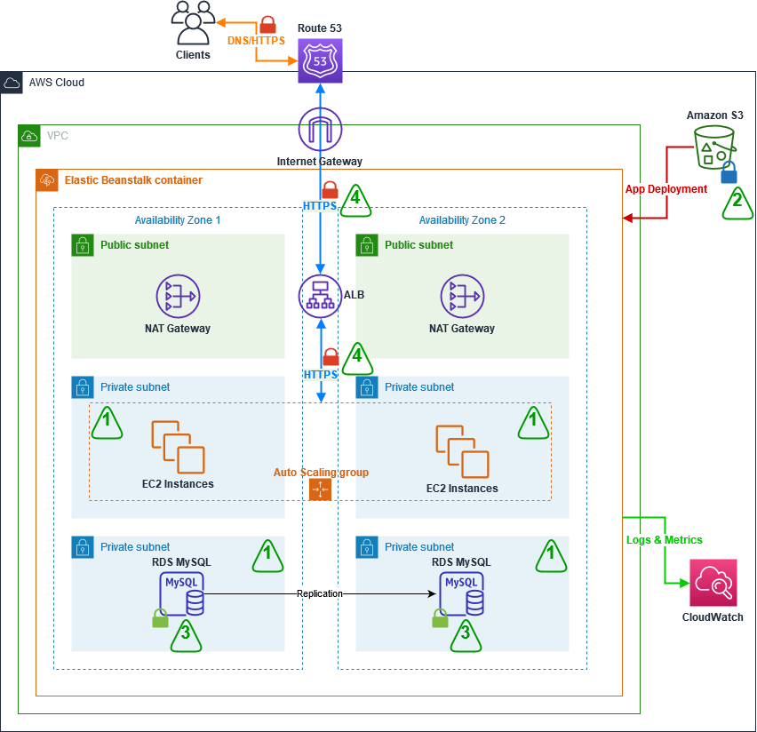
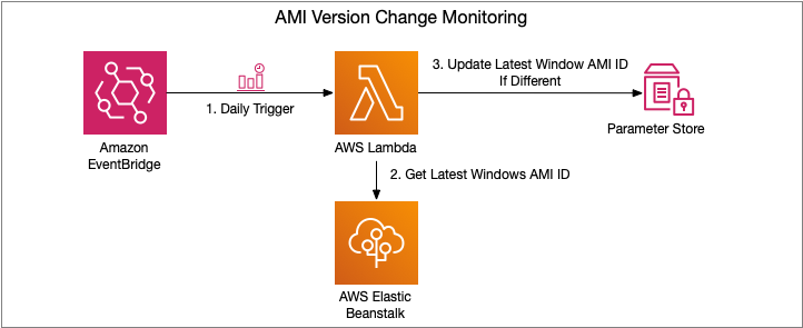
The following diagram illustrates the deployed solution.

Prerequisites and assumptions
To follow the steps outlined in this post, you need the following:
● An AWS account that provides access to AWS services.
● Node.js and npm installed on your local machine. If installing Node.js and npm on Mac, you can run the brew update and brew install node commands on your terminal. You can also download
Node.js for Windows. The Node.js installer for Windows also includes the npm package manager.
● The TypeScript compiler (tsc) installed on your local machine. Our sample application is developed using TypeScript, which is a superset of JavaScript. To install the TypeScript compiler, run
npm install -g typescript in your terminal.
Additionally, be aware of the following:
● The templates and code are intended to work in the us-east-1 region only and are only for demonstration purposes. This is not for production use.
● We configure all services in the same VPC to simplify networking considerations.
● The AWS CloudFormation templates and the sample code that we provide use hard-coded user names and passwords and open security groups.
Set up the initial GitLab environment
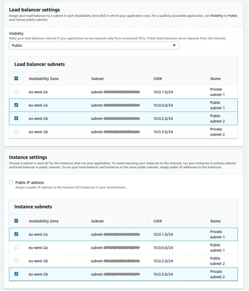
In this step, we set up the GitLab environment. To do so, we provision a VPC with an internet gateway, a public subnet, a route table, and a security group. The security group has one inbound rule to allow access to any TCP port from any VPC host configured to use the same security group. We use an Amazon Route 53 private hosted zone and an Amazon Simple Storage Service (Amazon S3) bucket to store input data and processed data. The template also downloads a sample application, pushes the code into the GitLab repository, and creates a deployment pipeline with GitLab CI/CD.
You can use this downloadable CloudFormation template to set up these components. To launch directly through the console, choose Launch Stack.

Provide a stack name and EC2 key pair. After you specify the template parameters, choose Next and create the CloudFormation stack. When the stack launch is complete, it should return outputs similar to the following.
| Key |
Value |
| StackName |
Name |
| VPCID |
vpc-xxxxxxxx |
| SubnetIDA |
subnet-xxxxxxxx |
| SubnetIDB |
subnet-xxxxxxxx |
| SubnetIDC |
subnet-xxxxxxxx |
| VPCSubnets |
VPCSubnetsList |
| AWSBLOGBEANAccessSecurityGroup |
Security group |
| GitEc2PublicDNS |
ec2-xx-xx-xx-xx.compute-1.amazonaws.com |
| GitEc2PublicIp |
xx-xx-xx-xx |
| ExpS3Bucket |
<bucket-that-was-created> |
Installing and configuring GitLab takes approximately 20 minutes. Wait until GitLab is completely configured and running.
Make a note of the output; you use this information in the next step. You can view the stack outputs on the AWS CloudFormation console or by using the following AWS Command Line Interface (AWS CLI) command:
aws cloudformation describe-stacks --stack-name <stack_name> --region us-east-1 --query 'Stacks[0].Outputs'
Log in to Gitlab and set up the SSH key and CI/CD token
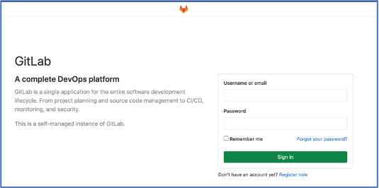
Next, log in to your newly provisioned GitLab environment. Use the public DNS name that was shown in the CloudFormation stack output to open your browser and enter the PublicDNS in the address bar. Provide the username root and password changeme to log in to the GitLab environment. These credentials are set in the gitlab-setup.sh script.

Figure-2
Update the SSH key in GitLab
After successful login, we need to add your local host’s SSH key to establish a secure connection between your local computer and GitLab. We need SSH access in order to clone the populated GitLab repository and push code changes in a later step.
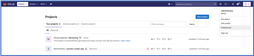
1. On the drop-down menu, choose Preferences.

Figure-3
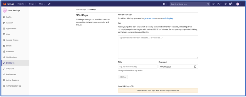
2. In the navigation pane, choose SSH Keys.
3. Get your public SSH key from your local computer and enter it in the Key section.

Figure-4
If using Mac, get your public key with the following code:
cat ~/.ssh/id_rsa.pub
On Windows, use the following code (make sure you replace [your user name] with your user name):
C:\Users\[your user name]\.ssh.
4. Choose Add key.
Add deploy tokens on the Gitlab console
For Elastic Beanstalk to pull the Docker image containing our sample Node.js app from the GitLab Container Registry, we need to create GitLab deploy tokens. Deploy tokens allow access to packages, your repository, and registry images.
1. Sign in to your GitLab account.
2. Choose sample-nodejs-app.
3. Under Settings, choose Repository.
4. In the Deploy tokens section, for Name, enter a name for your token.
5. For Scopes, select all the options.
6. Choose Create deploy token.

This creates the username as gitlab+deploy-token-1 and a token with random alphanumeric characters.
7. Save these values before navigating to some other screen because the token can’t be recovered.
Upon creation, you should see the deploy token creation message.

Add CI/CD variables on the GitLab console
The .gitlab-ci.yml file provides customized instructions for GitLab CI/CD. In our case, this file is configured to use GitLab CI/CD environment variables for the username, password, and S3 bucket values needed during the pipeline run. To set up these environment variables, complete the following steps:
1. On the Your Projects page, choose sample-nodejs-app.
2. On the Settings menu, choose CI/CD.
3. In the Variables section, add three variables to the pipeline (make sure you deselect Protect variable for each variable):
a. GIT_DEPLOYMENT_USER – Your username should be the same.
b. GIT_DEPLOYMENT_TOKEN – The value of the password that was generated as part of creating the deployment token.
c. S3_BUCKET_NAME – Created during the CloudFormation stack deployment. You can find the S3_BUCKET_NAME value on the Outputs tab for that stack on the AWS CloudFormation console.

After the three variables are created, you should see them listed.

Verify the sample Node.js application
The CloudFormation stack you deployed also downloads a sample application and pushes the code into your GitLab repository. To verify this, go to the Projects menu on the GitLab console and choose Your Projects. You should see sample-nodejs-app.
Provision a sample Elastic Beanstalk application and environment
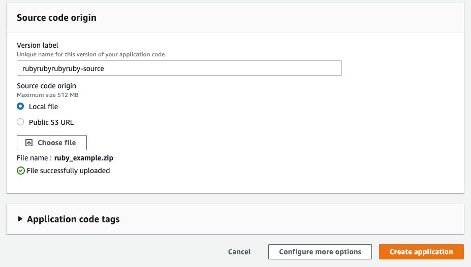
Now we create a sample Elastic Beanstalk application and environment. This step only creates an initial Elastic Beanstalk environment that we deploy to in the next step. You can use our downloadable CloudFormation template. To launch directly through the console, complete the following steps:
1. Choose Launch Stack.
2. Specify the template details and choose Next.
3. On the Specify stack details, provide the value for paramSolutionStackName. Get the latest name from
https://docs.aws.amazon.com/elasticbeanstalk/latest/platforms/platforms-supported.html#platforms-supported.docker
The value should be in the format of: “64bit Amazon Linux 2 vx.x.x running Docker”
4. On the Review page, choose Create.
This CloudFormation template takes around 10 minutes to complete.
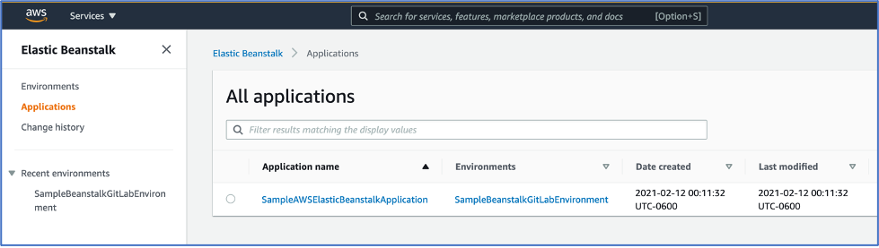
When the template is complete, you can see the newly created application and environment on the Elastic Beanstalk console.

Figure-9
The stack also creates a load balancer; we can use the hostname of that load balancer to connect to the application.
5. On the Elastic Load Balancing (ELB) console, choose the newly created load balancer and copy the DNS name.
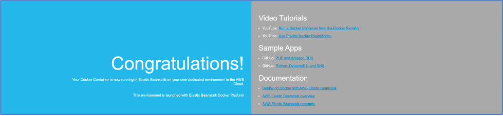
6. Enter the DNS name in the browser address bar.
A default page should appear.

Figure-10
Update and deploy application changes
Lastly, we clone sample-nodejs-app to your local machine, make a small change, and commit that change to initiate our CI/CD pipeline.
1. Sign in to GitLab and go to Your Projects.
2. Choose sample-nodejs-app.
3. On your local machine, create a directory where you want to download your repository and then clone your repository. The following commands are for a Mac:
mkdir -p ~/test/
cd ~/test/
git clone [email protected]:root/sample-nodejs-app.git
Don’t forget to check your instance’s security group and make sure port 22 is open to this instance from your network. Update the hostname in the preceding command with the public DNS name of your GitLab EC2 instance.
4. Run the following command to install the TypeScript module dependencies:
cd ~/test/sample-nodejs-app/
npm install @types/node @types/express @types/body-parser --save-dev
Compile the application using the tsc command:
The tsc command invokes the typescript compiler. It uses the tsconfig.json file to compile the application.
1. Enter the following code:
cd ~/test/sample-nodejs-app/
tsc
When the compilation is complete, it generates the dist directory.
2. Log in to your local machine and navigate to the directory where you copied the sample application.
3. Enter the following commands:
cd ~/test/sample-nodejs-app
git branch master
git checkout master
git add .
git commit -m "compiled application changes"
git push -u origin master
4. When the code push is complete, sign in to the GitLab console and choose sample-nodejs-app.
5. Under CI/CD, choose Pipelines.
You can see the pipeline being run. GitLab deploys the new version to the Elastic Beanstalk environment. Wait for the pipeline execution to be completed.
6. On the Elastic Beanstalk console, choose Environments.
7. Choose SampleBeanstalkGitLabEnvironment.
Your Elastic Beanstalk console should look similar to the following screenshot.

8. In the navigation pane, choose Go to environment.
You should see the sample webpage.

Modify the sample Node.js application (optional)
Because our application is now deployed and running, let’s make some changes to the sample application and push the code back to GitLab.
1. Go to your terminal and run the following commands to update the code and push your changes:
cd ~/test/sample-nodejs-app
cd src/routes
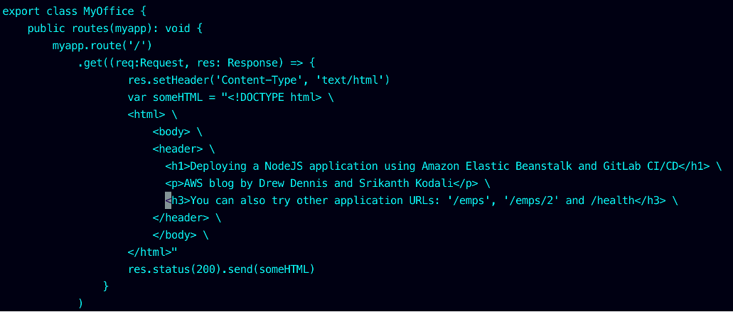
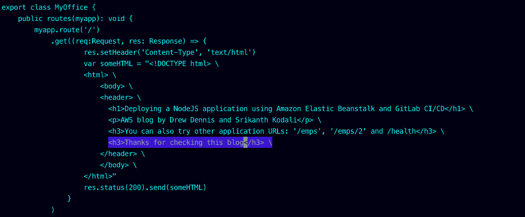
vi MyOffice.ts
The content of MyOffice.ts should look like the following screenshot.

Figure-13
2. Add an extra line in the <body> section.
This demonstrates making a simple change to the application. For this post, I added the line <h3>Thanks for checking this blog<h3>.

Figure-14
3. Save the file and push the code using the following commands:
cd ~/test/sample-nodejs-app/src/routes
git add MyOffice.ts
git commit -m "Updated MyOffice.ts file"
git push -u origin master
4. On the GitLab console, choose sample-nodejs-app.
5. Under CI/CD, choose Pipelines.
Once again, you can see the pipeline automatically gets runs to deploy the new version to your Elastic Beanstalk environment.
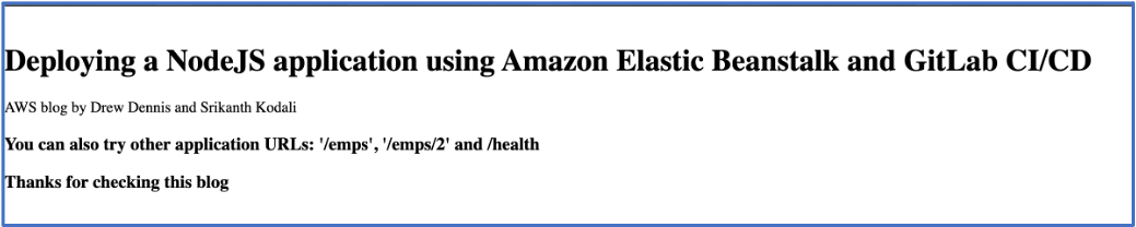
6. Now that the pipeline run is complete, we can go to the Elastic Beanstalk console, choose SampleBeanstalkGitLabEnvironment, and choose Go to environment.
Your results should look similar to the following screenshot.

Figure-15
Cleanup
Please remove all the deployed resources by un-provisioning Elastic Beanstalk application as well as the GitLab service to make sure there are no additional charges incurred after the tests are completed.
Conclusion
In this post, we showed how to deploy a Docker-based Node.js application on Elastic Beanstalk with GitLab’s DevOps platform. The associated resources in this post provide automation for setting up GitLab on Amazon EC2 and configuring a GitLab CI/CD pipeline that integrates with the GitLab Container Registry and Elastic Beanstalk. For additional information about the setup scripts, templates, and configuration files used, refer to the GitHub repository. Thank you for reading!
About the Authors

Srikanth Kodali
Srikanth Kodali is a Sr. IOT Data analytics architect at Amazon Web Services. He works with AWS customers to provide guidance and technical assistance on building IoT data and analytics solutions, helping them improve the value of their solutions when using AWS.
Drew Dennis
Drew Dennis is a Global Solutions Architect with AWS based in Dallas, TX. He enjoys all things Serverless and has delivered the Architecture Track’s Serverless Patterns and Best Practices session at re:Invent the past three years. Today, he helps automotive companies with autonomous driving research on AWS, connected car use cases, and electrification.