Post Syndicated from Eric Johnson original https://aws.amazon.com/blogs/compute/introducing-cross-account-amazon-ecr-access-for-aws-lambda/
This post is written by Brian Zambrano, Enterprise Solutions Architect and Indranil Banerjee, Senior Solution Architect.
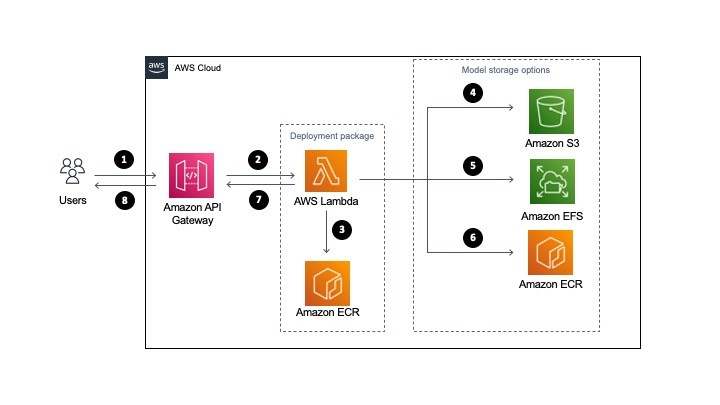
In December 2020, AWS announced support for packaging AWS Lambda functions using container images. Customers use the container image packaging format for workloads like machine learning inference made possible by the 10 GB container size increase and familiar container tooling.
Many customers use multiple AWS accounts for application development but centralize Amazon Elastic Container Registry (ECR) images to a single account. Until today, a Lambda function had to reside in the same AWS account as the ECR repository that owned the container image. Cross-account ECR access with AWS Lambda functions has been one of the most requested features since launch.
From today, you can now deploy Lambda functions that reference container images from an ECR repository in a different account within the same AWS Region.
Overview
The example demonstrates how to use the cross-account capability using two AWS example accounts:
- ECR repository owner: Account ID 111111111111
- Lambda function owner: Account ID 222222222222
The high-level process consists of the following steps:
- Create an ECR repository using Account 111111111111 that grants Account 222222222222 appropriate permissions to use the image
- Build a Lambda-compatible container image and push it to the ECR repository
- Deploy a Lambda function in account 222222222222 and reference the container image in the ECR repository from account 111111111111
This example uses the AWS Serverless Application Model (AWS SAM) to create the ECR repository and its repository permissions policy. AWS SAM provides an easier way to manage AWS resources with CloudFormation.
To build the container image and upload it to ECR, use Docker and the AWS Command Line Interface (CLI). To build and deploy a new Lambda function that references the ECR image, use AWS SAM. Find the example code for this project in the GitHub repository.
Create an ECR repository with a cross-account access policy
Using AWS SAM, I create a new ECR repository named cross-account-function in the us-east-1 Region with account 111111111111. In the template.yaml file, RepositoryPolicyText defines the permissions for the ECR Repository. This template grants account 222222222222 access so that a Lambda function in that account can reference images in the ECR repository:
AWSTemplateFormatVersion: '2010-09-09'
Transform: AWS::Serverless-2016-10-31
Description: SAM Template for cross-account-function ECR Repo

Resources:
  HelloWorldRepo:
    Type: AWS::ECR::Repository
    Properties:
      RepositoryName: cross-account-function
      RepositoryPolicyText:
        Version: "2012-10-17"
        Statement:
          - Sid: CrossAccountPermission
            Effect: Allow
            Action:
              - ecr:BatchGetImage
              - ecr:GetDownloadUrlForLayer
            Principal:
              AWS:
                - arn:aws:iam::222222222222:root
          - Sid: LambdaECRImageCrossAccountRetrievalPolicy
            Effect: Allow
            Action:
              - ecr:BatchGetImage
              - ecr:GetDownloadUrlForLayer
            Principal:
              Service: lambda.amazonaws.com
            Condition:
              StringLike:
                aws:sourceArn:
                  - arn:aws:lambda:us-east-1:222222222222:function:*

Outputs:
  ERCRepositoryUri:
    Description: "ECR RepositoryUri which may be referenced by Lambda functions"
    Value: !GetAtt HelloWorldRepo.RepositoryUri
The RepositoryPolicyText has two statements that are required for Lambda functions to work as expected:
- CrossAccountPermission – Allows account 222222222222 to create and update Lambda functions that reference this ECR repository
- LambdaECRImageCrossAccountRetrievalPolicy – Lambda eventually marks a function as INACTIVE when not invoked for an extended period. This statement is necessary so that Lambda service in account 222222222222 can pull the image again for optimization and caching.
To deploy this stack, run the following commands:
git clone https://github.com/aws-samples/lambda-cross-account-ecr.git
cd sam-ecr-repo
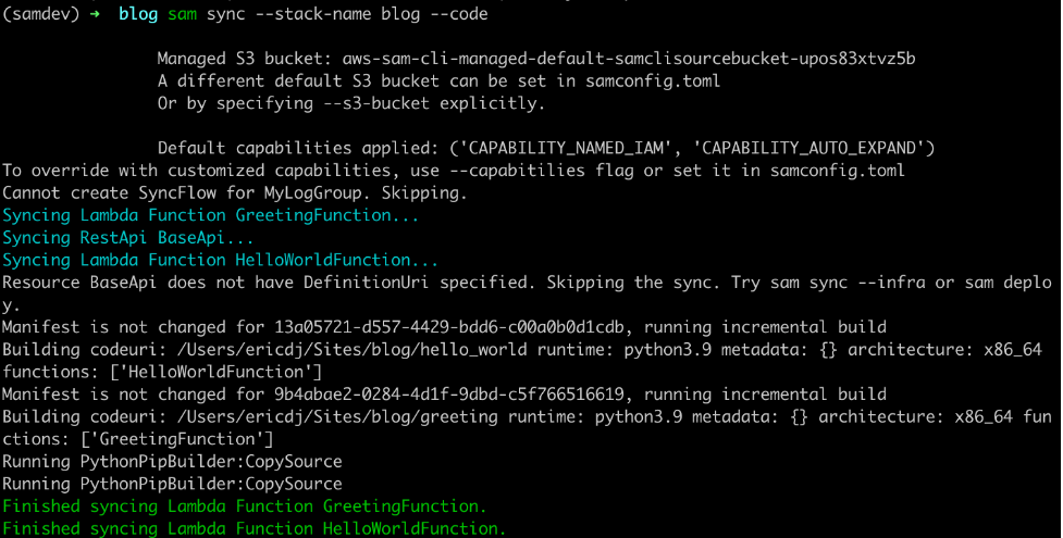
sam build
AWS SAM build results
sam deploy --guided
AWS SAM deploy results
Once AWS SAM deploys the stack, a new ECR repository named cross-account-function exists. The repository has a permissions policy that allows Lambda functions in account 222222222222 to access the container images. You can verify this in the ECR console for this repository:
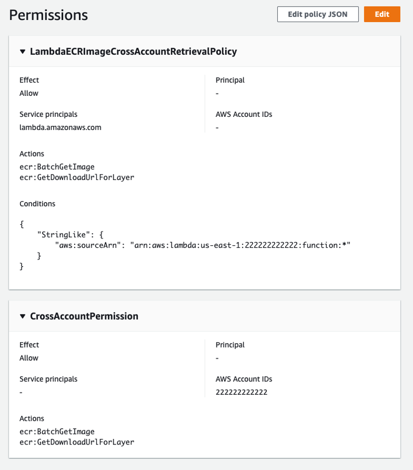
Permissions displayed in the console
You can also extend this policy to enable multiple accounts by adding additional account IDs to the Principal and Condition evaluations lists in the CrossAccountPermission and LambdaECRImageCrossAccountRetrievalPolicy permissions policy. Narrowing the ECR permission policy is a best practice. With this launch, if you are working with multiple accounts in an AWS Organization we recommend enumerating your account IDs in the ECR permissions policy.
Amazon ECR repository policies use a subset of IAM policies to control access to individual ECR repositories. Refer to the ECR repository policies documentation to learn more.
Build a Lambda-compatible container image
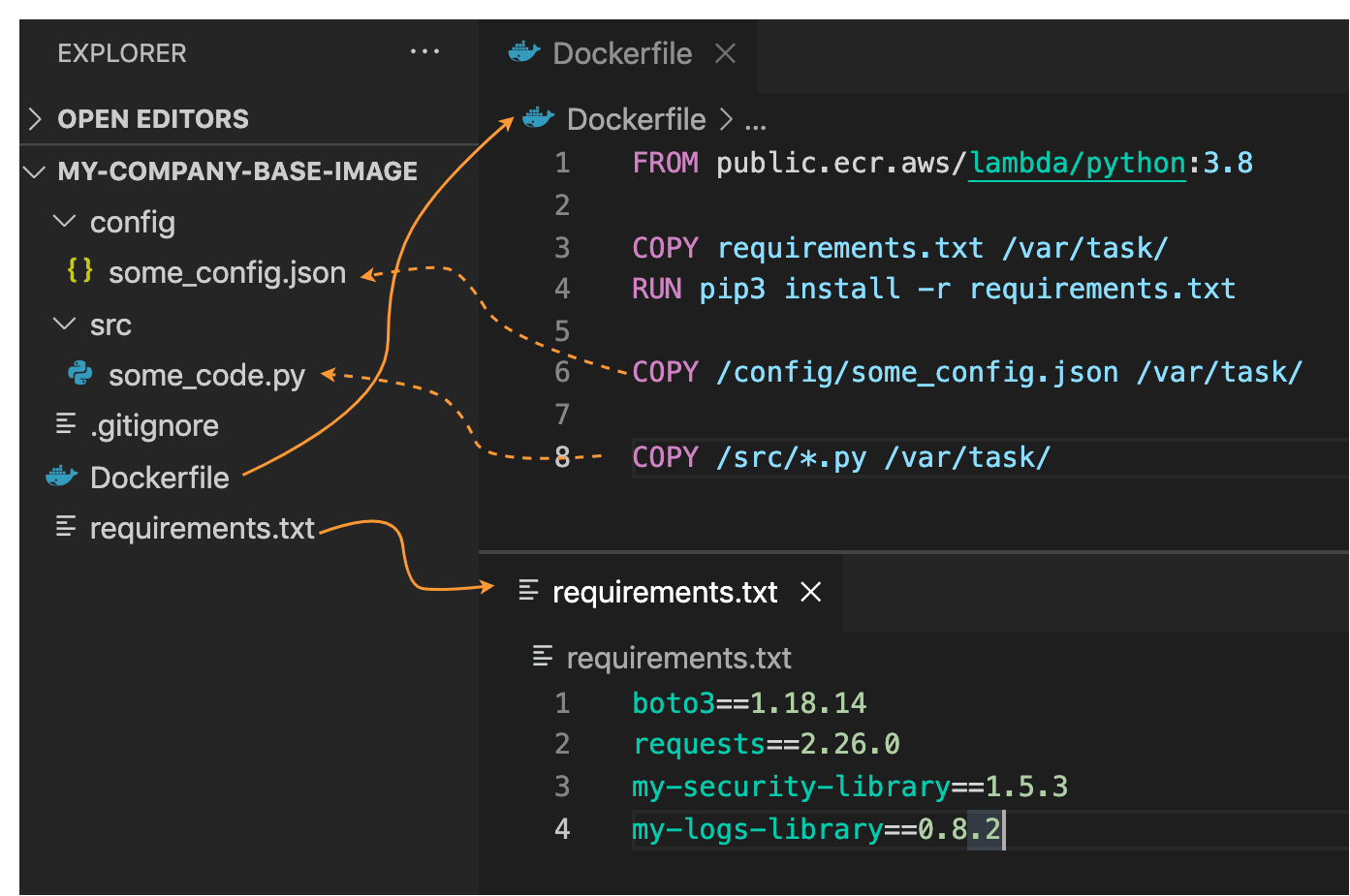
Next, you build a container image using Docker and the AWS CLI. For this step, you need Docker, a Dockerfile, and Python code that responds to Lambda invocations.
- Use the AWS-maintained Python 3.9 container image as the basis for the Dockerfile:
FROM public.ecr.aws/lambda/python:3.9
COPY app.py ${LAMBDA_TASK_ROOT}
CMD ["app.handler"]
The code for this example, in app.py, is a Hello World application.
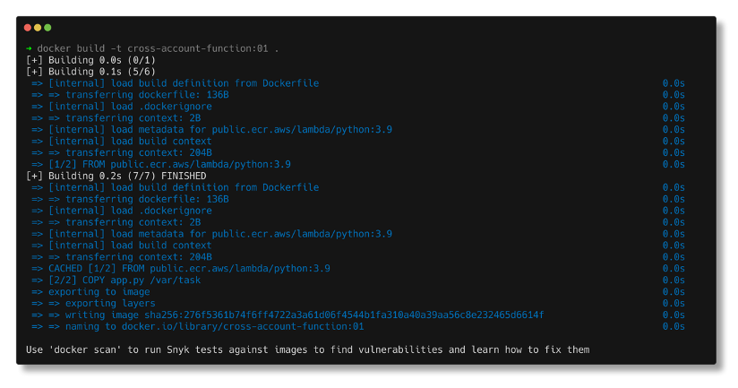
import json def handler(event, context): return { "statusCode": 200, "body": json.dumps({"message": "hello world!"}), } - To build and tag the image and push it to ECR using the same name as the repository (cross-account-function) for the image name and 01 as the tag, run:
$ docker build -t cross-account-function:01 .
Docker build results
- Tag the image for upload to the ECR. The command parameters vary depending on the account id and Region. If you’re unfamiliar with the tagging steps for ECR, view the exact commands for your repository using the View push commands button from the ECR repository console page:
$ docker tag cross-account-function:01 111111111111.dkr.ecr.us-east-1.amazonaws.com/cross-account-function:01 - Log in to ECR and push the image:
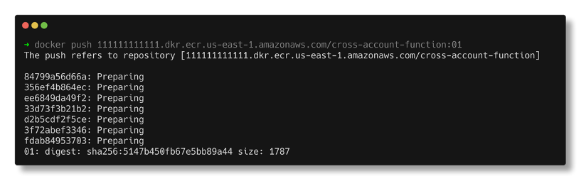
$ aws ecr get-login-password --region us-east-1 | docker login --username AWS --password-stdin 111111111111.dkr.ecr.us-east-1.amazonaws.com
$ docker push 111111111111.dkr.ecr.us-east-1.amazonaws.com/cross-account-function:01
Docker push results
Deploying a Lambda Function
The last step is to build and deploy a new Lambda function in account 222222222222. The AWS SAM template below, saved to a file named template.yaml, references the ECR image for the Lambda function’s ImageUri. This template also instructs AWS SAM to create an Amazon API Gateway REST endpoint integrating the Lambda function.
AWSTemplateFormatVersion: '2010-09-09'
Transform: AWS::Serverless-2016-10-31
Description: Sample SAM Template for sam-ecr-cross-account-demo

Globals:
  Function:
    Timeout: 3
Resources:
  HelloWorldFunction:
    Type: AWS::Serverless::Function
    Properties:
      PackageType: Image
      ImageUri: 111111111111.dkr.ecr.us-east-1.amazonaws.com/cross-account-function:01
      Architectures:
        - x86_64
      Events:
        HelloWorld:
          Type: Api
          Properties:
            Path: /hello
            Method: get

Outputs:
  HelloWorldApi:
    Description: "API Gateway endpoint URL for Prod stage for Hello World function"
    Value: !Sub "https://${ServerlessRestApi}.execute-api.${AWS::Region}.amazonaws.com/Prod/hello/"
Use AWS SAM to deploy this template:
cd ../sam-cross-account-lambda
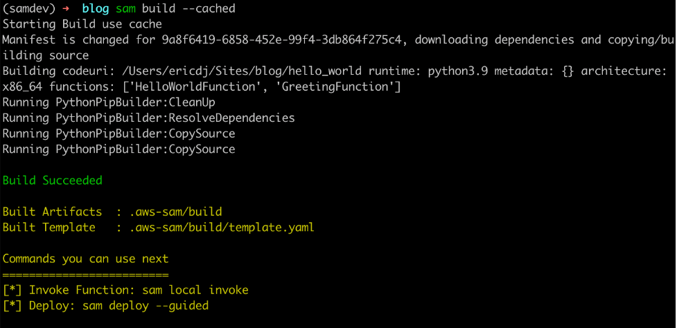
sam build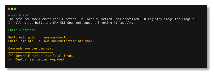
AWS SAM build results
sam deploy --guided
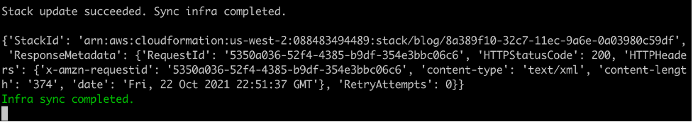
SAM deploy results
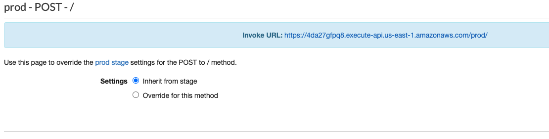
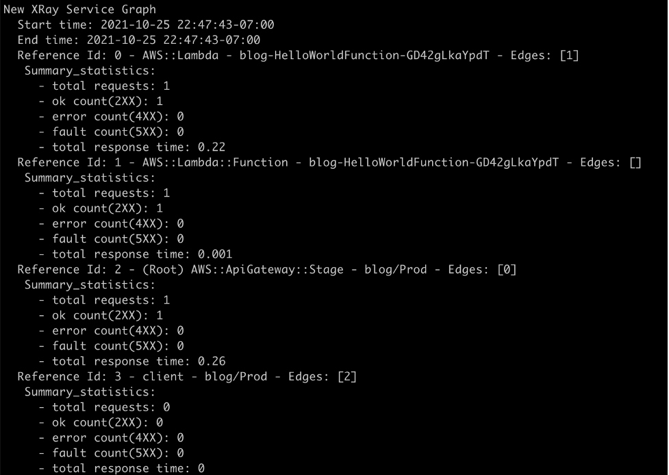
Now that the Lambda function is deployed, test using the API Gateway endpoint that AWS SAM created:

Testing the endpoint
Because it references a container image with the ImageUri parameter in the AWS SAM template, subsequent deployments must use the –resolve-image-repos parameter:
sam deploy --resolve-image-reposConclusion
This post demonstrates how to create a Lambda-compatible container image in one account and reference it from a Lambda function in another account. It shows an example of an ECR policy to enable cross-account functionality. It also shows how to use AWS SAM to deploy container-based functions using the ImageUri parameter.
To learn more about serverless and AWS SAM, visit the Sessions with SAM series and find more resources at Serverless Land.
#ServerlessForEveryone


 Note the template parameters:
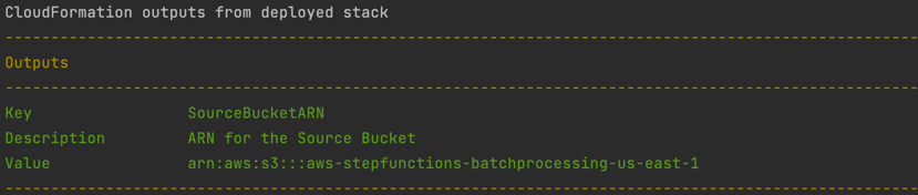
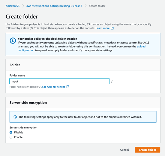
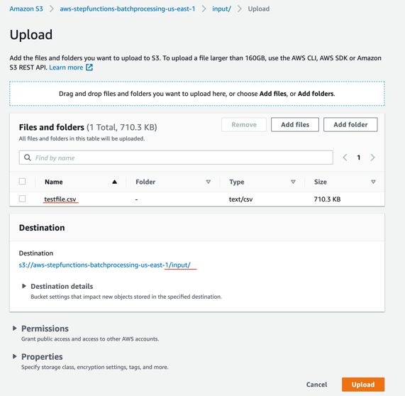


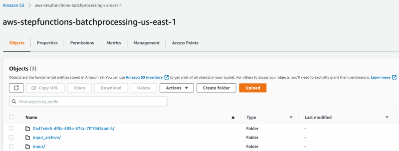
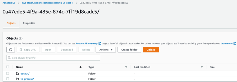
 to_process – This folder contains all the split objects from the original input file.
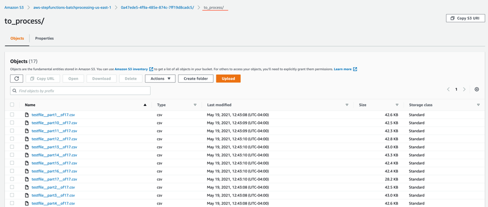


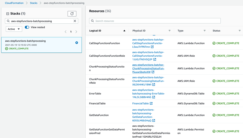
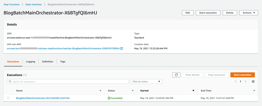
 After stack creation, you see