The 2024 Gartner Magic Quadrant for DaaS (Desktop as a Service) positions AWS as a Leader for the first time. Last year we were recognized as a Challenger. We believe this is a result of our commitment to meet a wide range of customer needs by delivering a diverse portfolio of virtual desktop services with license portability (including Microsoft 365 Apps for Enterprise), our geographic strategy, and operational capabilities focused on cost optimization and automation. Also, our focus on easy-to-use interfaces for managing each aspect of our virtual desktop services means that our customers rarely need to make use of third-party tools.
AWS DaaS Offerings Let’s take a quick look at our lineup of DaaS offerings (part of our End User Computing portfolio):
Amazon WorkSpaces Family – Originally launched in early 2014 and enhanced frequently ever since, Amazon WorkSpaces gives you a desktop computing environment running Microsoft Windows, Ubuntu, Amazon Linux, or Red Hat Enterprise Linux in the cloud. Designed to support remote & hybrid workers, knowledge workers, developer workstations, and learning environments, WorkSpaces is available in sixteen AWS Regions, in your choice of six bundle sizes, including the GPU-equipped Graphics G4dn bundle. WorkSpaces Personal gives each user a persistent desktop — perfect for developers, knowledge workers, and others who need to install apps and save files or data. If your users do not need persistent desktops (often the case for contact centers, training, virtual learning, and back office access) you can use WorkSpaces Pools to simplify management and reduce costs. WorkSpaces Core provides managed virtual desktop infrastructure that is designed to work with third-party VDI solutions such as those from Citrix, Leostream, Omnissa, and Workspot.
Amazon AppStream 2.0 – Launched in late 2016, Amazon AppStream gives you instant, streamed access to SaaS applications and desktop applications without writing code or refactoring the application. You can easily scale applications and make them available to users across the globe without the need to manage any infrastructure. A wide range of compute, memory, storage, GPU, and operating system options let you empower remote workers, while also taking advantage of auto-scaling to avoid overprovisioning. Amazon AppStream offers three fleet types: Always on (instant connections), On-Demand (2 minutes to launch), and Elastic (for unpredictable demand). Pricing varies by type, with per second and per hour granularity for Windows and Linux; read Amazon AppStream 2.0 Pricing to learn more.
Gartner does not endorse any vendor, product or service depicted in its research publications and does not advise technology users to select only those vendors with the highest ratings or other designation. Gartner research publications consist of the opinions of Gartner’s research organization and should not be construed as statements of fact. Gartner disclaims all warranties, expressed or implied, with respect to this research, including any warranties of merchantability or fitness for a particular purpose.
GARTNER is a registered trademark and service mark of Gartner and Magic Quadrant is a registered trademark of Gartner, Inc. and/or its affiliates in the U.S. and internationally and are used herein with permission. All rights reserved.
This graphic was published by Gartner, Inc. as part of a larger research document and should be evaluated in the context of the entire document. The Gartner document is available upon request from AWS.
The new Amazon WorkSpaces Thin Client improves end-user and IT staff productivity with cost-effective, secure, easy-to-manage access to virtual desktops. The devices are preconfigured and shipped directly to the end user, ready to deploy, connect, and use.
Here’s my testing setup:
The Thin Client is a small cube that connects directly to a monitor, keyboard, mouse, and other USB peripherals such as headsets, microphones, and cameras. With the optional hub it can also drive a second monitor. The administrator can create environments that give users access to Amazon WorkSpaces, Amazon WorkSpaces Web, or Amazon AppStream 2.0, with multiple options for managing user identities and credentials using Active Directory.
Thin Clients in action As a very long-time user of Amazon WorkSpaces via a thin client, I am thrilled to be able to tell you about this device and the administrative service behind it. While my priority is the ease with which I can switch from client to client while maintaining my working context (running apps, browser tabs, and so forth), administrators will find it attractive for other reasons. For example:
Cost – The device itself is low cost ($195 in the United States), far less expensive than a laptop and the associated operating system. Because the working environments are centrally configured and administered, there’s less work to be done in the field, leading to further cost savings. Further, the devices are far simpler than laptops, with less parts to break, wear out, or replace.
Security – The devices are shipped with a secure “secret” that is used to establish a trust relationship with the administrative service. There’s no data storage on the device, and it cannot host rogue apps that could attempt to exfiltrate data. It also helps to reduce risk of data leakage should a worker leave their job without returning their employer-supplied laptop.
Ease of Management – Administrators can easily create new environments for users or groups of users, distribute activation codes to them, and manage the environment via the AWS Management Console. They can set schedules for software updates and patches, verify compliance, and manage users over time.
Ease of Use – Users can unpack and connect the devices in minutes, enter their activation codes, log in to their virtual desktop environment, and start to work right away. They don’t have to take responsibility for installing software patches or updates, and can focus on their jobs.
There are lots of great use cases for these devices! First, there are situations where there’s a long-term need for regular access: call centers, task workers, training centers, and so forth. Second, there are other situations, where there’s a transient or short-term need for access: registration systems at large events, call centers stood up on a temporary basis for a special event or an emergency, disaster response, and the like. Given that some employees do not return laptops to their employers when they leave their job, providing them with inexpensive devices that do not have local storage makes a lot of sense.
Let’s walk through the process of getting set up, first as an administrator and then as a user.
Getting started as an administrator The first step is to order some devices and have them shipped to my users, along with any desired peripherals.
Next, in my position as administrator, I open the Amazon WorkSpaces Thin Client Console, and click Get started:
Each Amazon WorkSpaces Thin Client environment provides access to a specific virtual desktop service (WorkSpaces, WorkSpaces Web, or Amazon AppStream 2.0). I click Create environment to move ahead:
I give my environment a name, indicate that I want patches applied automatically, and select WorkSpaces Web:
Next, I click Create WorkSpaces Web portal and go through those steps (not shown, basically choosing a VPC and two or more subnets, a security group, and an optional Private Certificate Authority):
I refresh, and my new portal is visible. I select it, enter a tag for tracking, and click Create environment:
My environment is ready right away. I keep a copy of the activation code (aci3a5yj) at hand to use later in the post:
I am using AWS Identity Center as my identity provider. I already set up my first user, and assigned myself to the MyWebPortal app (the precise steps that you take to do this will vary depending on your choice of identity provider):
Finally, as my last step in this process in my role as administrator, I share the activation code with my users (that would be me, in this case).
Getting started as a user In my role as a user I return to my testing setup, power-on, go through a couple of quick steps to select my keyboard and connect to my home Wi-Fi, and enter my activation code:
Then I sign in using my AWS Identity Center user name and password:
And my WorkSpace is ready to use:
Administrator tools As an administrator, I can manage environments, devices, and device software updates from the Thin Client Console. For example, I can review the list of devices that I manage:
Things to know Here are a couple of things that are important to know:
Regions – The Thin Client Console is available in the US East (N. Virginia), US West (Oregon), Asia Pacific (Mumbai), Canada (Central), and Europe (Frankfurt, Ireland, Ireland, London) Regions.
Device Sales – The Amazon WorkSpaces Thin Clients are available in the United States now, with availability in other countries in early 2024.
Pricing – Devices are priced at $195, or $280 with an optional hub that allows you to use a second monitor. There’s a $6 per month fee to manage, maintain, and monitor each device, and you also pay for the underlying virtual desktop service.
Healthcare technology, commonly referred to as “health tech,” is the use of technologies developed for the purpose of improving any and all aspects of the healthcare system. For example, IT tools or software designed to boost hospital/administrative productivity, give insights into new and existing treatments, or improve the overall quality of care.
Also known as “digital health”, health tech uses databases, applications, mobile devices, and wearables to facilitate the delivery, payment, and/or consumption of healthcare. The increased accessibility to these technologies can further increase the development and launch of additional healthcare products.
In this post, we explore how to build and manage health tech architectures using Amazon Web Services (AWS).
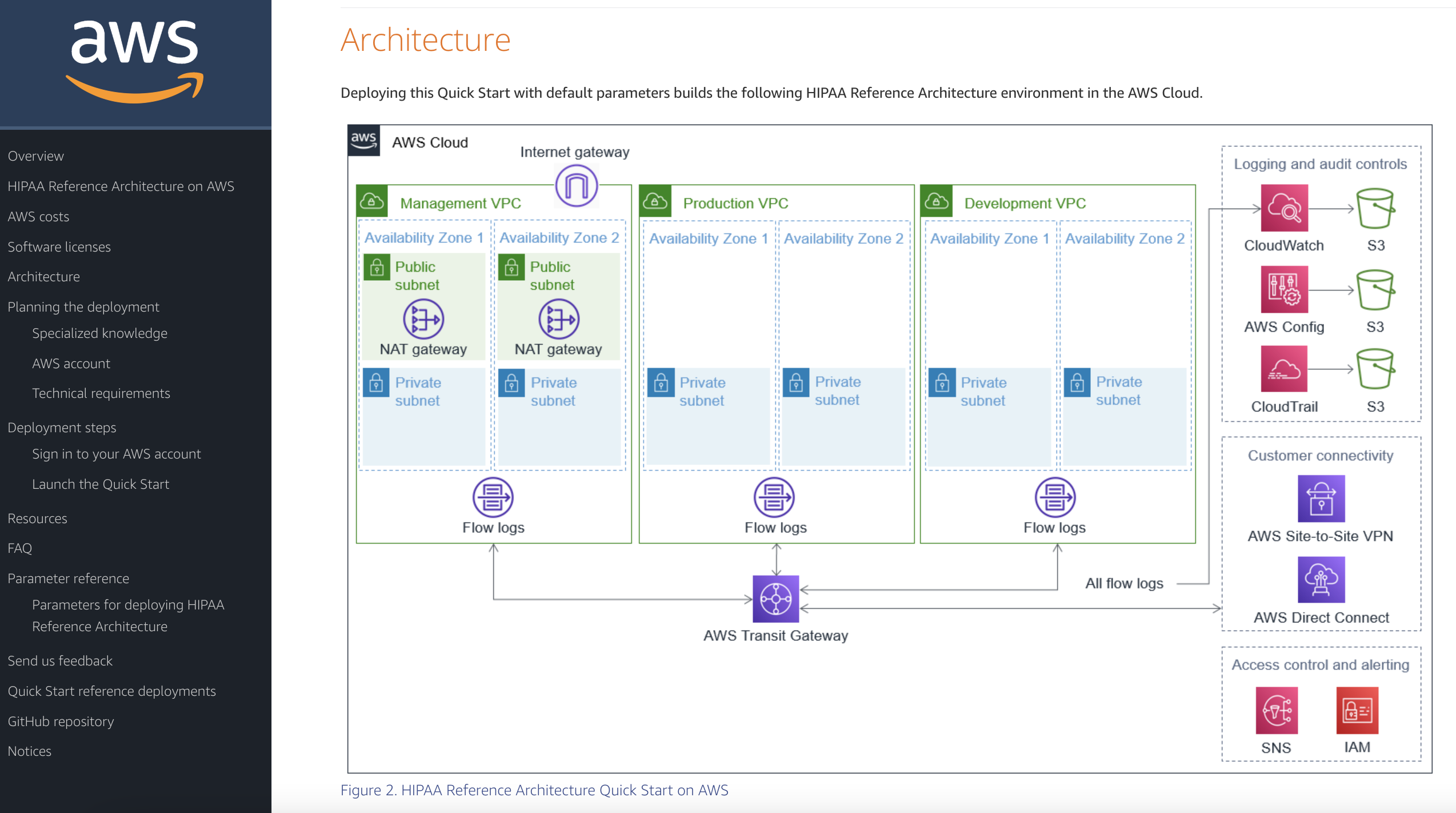
This Quick Start provides guidance for deploying a U.S. Health Insurance Portability and Accountability Act (HIPAA) architecture on the AWS Cloud. Specifically, this aims to help those in the healthcare industry build and implement HIPAA-ready environments that fit with an organization’s larger HIPAA compliance program. It includes AWS CloudFormation templates that are customizable, plus automatically deploy the environment and configure AWS resources.
Amazon AppStream 2.0 is a fully managed, non-persistent desktop and application service for remotely accessing your work. This means that clinical staff can now access the medical applications and data they need from anywhere. Benefits of using AppStream 2.0 include reduced overhead cost. This Architecture Blog post examines how to construct the AWS architecture for an image analysis application used in clinical trials, while keeping cost down. Furthermore, it demonstrates how something seemingly complex can be built with ease using both AWS services and image analysis applications already in place.
Data veracity is fundamental. Patient data is confidential, and when a system deals with sensitive data, there needs to be a clear chain of ownership.
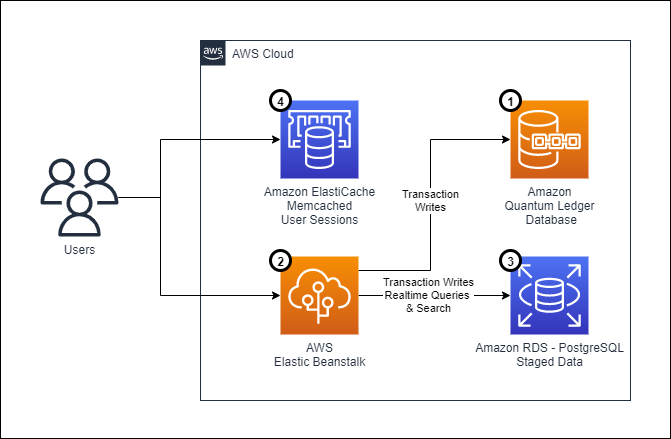
This blog post depicts an architecture based on the use of Amazon Quantum Ledger Database (Amazon QLDB), which addresses the need for data integrity and verifiability in healthcare. By using Amazon QLDB, the team can take advantage of an append-only journal to create a verifiable electronic medical record.
Also explored are the challenges architects face while working on these types of systems, as well as considerations about security, operational efficiency, processes for repeatable deployments using infrastructure as code, and data replication across multiple databases. The design choices architects make when developing a system depend on the context; read more about the mental models adopted in this use case.
Service Workbench on AWS is a cloud solution that enables IT teams to provide secure, repeatable, and federated control of access to data, tooling, and compute power. Service Workbench can help redirect researchers’ focus from technical duties back to the research itself, by allowing them to automate of the creation of baseline research setups and providing data access. It gives researchers the ability to build research environments in minutes without having to know about cloud infrastructure or wait for research IT to respond. It is fully HIPAA-compliant and allows for secure peer-to-peer collaboration, including with individuals from other institutions.
See you next time!
Thanks for joining our discussion on health tech architectures! See you in two weeks for more architecture best practices and guidance.
Volotea is one of the fastest growing independent airlines in Europe, and has increased its fleet, routes, and number of available seats year over year. Volotea has already transported more than 30 million passengers across Europe since 2012, and has bases in 16 European capitals.
The maintenance, repair, and overhaul (MRO) application is a critical system for every airline. It’s used to manage the maintenance, repair, service, and inspection of aircraft. The main goal of an MRO application is to ensure the safety and airworthiness of the aircraft. Traditionally, those systems have been based on monolithic, packaged applications. However, these are difficult to scale and do not offer the benefit of elasticity to adapt to changing demand. Volotea migrated to Amazon Web Services (AWS) to modernize their MRO without refactoring the code. In this blog post, we’ll show you an architecture solution that can be applied to modernize an MRO (or similarly packaged monolithic application) without refactoring, and discuss some considerations.
The challenges with an on-premises MRO solution
Volotea’s MRO software previously ran in an on-premises data center. The system was based on Windows, an outdated database engine, and a virtual desktop system based on Citrix. Costs were fixed, yet MRO usage is typically seasonal. All the interfaces with other systems were based on an outdated communications protocol. This presented security concerns, especially considering that ransomware attacks are an increasing threat.
The main challenge for Volotea was adapting the MRO system to changing business requirements. Seasonal workloads and high impact projects, like changing fleets from Boeing to Airbus, require flexibility. The company also needed to adapt to the changing protocols necessitated by the COVID-19 pandemic, as airlines are one of the most impacted industries in Europe.
Volotea needed to modernize the operating system (OS) and database, simplify the end user application access, and increase the overall platform security, including integration with other applications.
Modernizing the MRO without refactoring
Following Volotea’s cloud strategy, the MRO system was migrated in 2 months to AWS to reduce technology costs and gain higher operational performance, availability, security, and flexibility. The migration was not simply based on a lift-and-shift approach, but used an existing AWS reference architecture for the MRO system. This reference architecture incorporates AWS managed services to modernize the application without incurring refactoring costs.
Figure 1. Volotea MRO deployment in a multi-account architecture
As shown in the high-level architecture in Figure 1:
Volotea migrated their servers to Amazon EC2 instances based on Linux, to minimize the OS costs. The database management system is now using an open source engine. Those changes have permitted saving more than €10K yearly in licenses.
The user access technology was migrated to Amazon AppStream 2.0. This is a managed service with increased security, elasticity, and flexibility compared to traditional virtual desktop infrastructure (VDI) solutions. Volotea aligned the cost with the real usage and decreased the TCO by configuring Auto Scaling fleets, reducing the workplace costs by 50%.
AWS Transfer Family was used to centralize the information exchanged with third-party applications, while increasing the security of the communication channel. This managed service enabled the migration of the SFTP, FTPS, and FTP interfaces without the need to manage servers.
To modernize the access of the MRO administrators, AWS Systems Manager Session Manager was used. This provided an ideal browser-based shell access without requiring bastion hosts or opening SSH ports in the Amazon EC2 instances.
The AWS services were linked to Volotea’s user directory using AWS Single Sign-On. This allowed users to authenticate with their corporate credentials, decreasing maintenance costs, and increasing the security.
The application was deployed in Volotea’s AWS Landing Zone, which included the following services:
AWS Control Tower to set up and govern a secure, multi-account AWS environment.
AWS Transit Gateway to facilitate the networking and routing between different VPCs, accounts, and on-premises environments.
To make the systems management homogeneous, AWS Systems Manager and AWS Backup offered a single management point for the backup policies, system inventory, and patching.
Incorporating high availability to the MRO
Once this initial modernization is finished, Volotea will use the AWS reference architecture for high availability (HA) to increase resiliency. They’ll configure Amazon EC2 Auto Scaling with application failover to another Availability Zone and the DB native replication mechanisms. This will use Elastic IP addresses to remap the endpoints in a failover scenario. This architecture can be easily implemented in AWS to incorporate HA to applications that do not natively support horizontal scaling.
Conclusion
Volotea successfully modernized its MRO software, which has given them greater flexibility, elasticity, and the increased security of AWS services. They intend to continue with their digital transformation journey. Volotea is increasing its capacity to innovate faster to deliver new digital services more efficiently and with reduced IT costs. The AWS services and strategies discussed in this blog post can be applied to other similarly packaged applications to implement a first level of modernization with little effort and low migration risk.
The Open Microscopy Environment (OME) consortium develops open-source software and format standards for microscopy data. OME Remote Objects (OMERO) is an open source, image data management platform designed to support digital pathology and cellular biology studies. You can access, share, and work with various biological data. This can include histopathology, high content screening, electron microscopy, and even non-image genotype data. Deploying this open source tool on Amazon Web Services (AWS) allows you to access your image data in a secure central repository. You can take advantage of elastic storage by growing the archive as needed without provisioning excess storage beforehand. OMERO has a web interface, which facilitates data access and visualization. It also supports connection through the OMERO client or other third-party image analysis tools, like CellProfilerTM, QuPath, Fiji, ImageJ, and others.
The challenge of microscopy data
Saint Louis University (SLU) School of Medicine Research Microscopy and Histology Core required a centralized system for both distribution and hosting. The solution must provide research imaging distribution to both internal and external clients. It also needed the capability of hosting an educational platform for microscope images. SLU decided that the open source software OMERO was an ideal fit for them.
In order to provide speed, ease of access, and security for the University’s computer networks, SLU decided the solution must be hosted in the cloud. By partnering with AWS, SLU established a robust system for their clients. The privately hosted images on OMERO represent research material databases used by University researchers. OMERO also hosts teaching datasets for resident and fellow education. Other publicly hosted repositories provide access to source images for future publishing standards and regulations. SLU reported that the implementation was extraordinarily smooth for a non-programmer. In addition, the system design allowed for advanced data management to control costs and security.
Reviewing the OMERO architecture
OMERO is a typical three-tier web application, consisting of the following components:
OMERO.web provides access to OMERO’s data hierarchies and also enables annotation, organization, and visualization of data. This web browser-based client of OMERO.server exposes the annotation-based data-sharing mechanism.
OMERO.server is a middleware server application that provides access to image data and metadata stored in a series of databases. It contains a multi-threaded, image-rendering engine and supports a wide range (>140) of image pyramid formats through the Bio-Formats Java library. This Java application facilitates remote access and interoperability for modern scientific studies. It also exposes an API to allow any OMERO client to access the original data and any derived measurements.
OMERO relational database (PostgreSQL) provides the underlying storage facilities. This storage backend contains the processed metadata associated with the binary images, measurement specification, user information, structured annotations, and more.
Figure 1. Architectural diagram for a highly available (HA) deployment of OMERO on AWS including data ingestion options
To achieve the highly available (HA) deployment in the diagram, follow the guidance from this GitHub repository. Since OMERO only supports one writer per mounted network file share, there is one OMERO read+write server and one read-only server in the HA deployment. Otherwise, multiple instances will compete to get first access to Amazon Elastic File System (EFS). If HA is not a requirement, you can lower costs by deploying only the read+write OMERO.server.
OMERO is deployed on AWS using AWS CloudFormation (CFN) templates, which will deploy two nested CFN stacks, one for storage, and one for compute. The storage template creates an EFS volume and an Amazon Relational Database Service (RDS) instance of PostgreSQL. EFS provides the option to move files to an infrequent accessed storage class after a certain number of days to save storage cost. RDS has Multi-AZ option to improve business continuity. The compute template creates Amazon Elastic Container Service (Amazon ECS) containers for the OMERO web and server functions. You have the option to deploy the OMERO containers on AWS Fargate or Amazon EC2 launch type. It also creates an Amazon Application Load Balancer (ALB) with duration-based stickiness enabled and an AWS Certificate Manager (ACM) certificate for Transport Layer Security (TLS) termination at ALB. Only the ALB is publicly accessible, as the web portal is protected behind it in private subnets. VPC and subnets are required, which can be obtained via this CFN template. It also requires the hosted zone ID and fully qualified domain name in Amazon Route 53, which will be used to validate the TLS certificate. If higher security is not a requirement, there is an option to deploy without the registered domain and the hosted zone in Route 53. You will then be able to access the OMERO web through Application Load Balancer DNS name without TLS encryption.
Additionally, the containers of OMERO.web and OMERO.server can be extended with plugins. The landing page for login can be customized with logos, brands, or disclaimers. Build a new Docker container image with specific configuration changes to enrich the functionality of this open source platform.
You can use Amazon ECS Exec to access the OMERO command line interface (CLI) to import images within the OMERO.server container, running on either AWS Fargate or EC2 launch type. You can also run Amazon ECS Exec via AWS CloudShell. The OMERO CFN templates enable Amazon ECS Exec commands by default. You will only need to install AWS CLI and SSM plugin on your clients or AWS CloudShell to initiate the commands. When you import images within the OMERO.server container instances, you can use the OMERO in-place import to avoid redundant copies of the image files on Amazon EFS. Alternatively, you can access the Windows desktop OMERO client OMERO.insight, via the application virtualization service Amazon AppStream 2.0. This connects to the OMERO.server in the same VPC. Amazon AppStream 2.0 allows Amazon S3 being used as home folder storage, so you can import images directly from Amazon S3 to OMERO.server.
AWS offers multiple options to move your microscopic image data from on premises facilities to the cloud storage, as illustrated in Figure 1:
Researchers and scientists at St. Louis University were able to grow their image repository on AWS without the concern of fixed storage limits. They can scale their compute environment up or down as their research requirements dictate. The managed services, like Amazon ECS and RDS, are able to significantly reduce the operational workloads from researchers. SLU reports that this platform is of great use to their researchers. Other universities, academic medical centers, and pharmaceutical and biotechnology companies can also use this cloud-based image data management platform to collect, visualize, and share access to their image data assets.
Hospitals and clinical trial sites manage sensitive patient data. They are often required to grant remote access to custom Windows-based applications for patient record review and medical image analysis. This typically requires providing physicians and staff with remote access to on-premises workstations over VPN, with some flavor of remote desktop software. This can be both costly and inefficient, since it requires licensing custom 3rd party remote access tools, configuring network access for each researcher, and training individuals at each site for every trial. In combination with other AWS services, Amazon AppStream 2.0 can be used to build better workflows. Applications delivered via AppStream 2.0 can be used to review patient data, such as medical images, videos, and patient records. At the same time, this approach offers greater protection of patient data, without the cost and complexity of a remote desktop solution. In this blog, we will present a high-level architecture and several example use cases for leveraging AppStream 2.0 for medical image analysis.
Background – managing patient data security
Picture archiving and communications systems (PACS) and vendor neutral archives (VNAs) are used extensively for storing and managing medical images and related metadata. These systems are critical for sharing images among modern medical teams collaborating on patient care. Furthermore, researchers and clinicians can access images from PACS and view them at a workstation in an office or clinic setting.
While data sharing is critical for healthcare and research workflows, HIPAA-covered entities are responsible for protecting patient’s personally identifiable information (PII) as protected health information (PHI). As such, HIPAA-covered entities are bound to protect any information about a patient’s healthcare, health status, and payment history for services.
Data sovereignty leads to further complications. Clinical trials play an essential role in vouching for the safety and efficacy of medical products and innovations. The increasing transparency in clinical trial data makes sharing this information among researchers, clinicians, patients, and trial subjects possible. However, this also makes it a challenge to maintain stakeholder’s control over their data. With laws like General Data Protection Regulation (GDPR) and the emphasis on data localization, data sovereignty is interpreted based on the location of the data. Further, regulations like 21 CFR Part 11 impose strict guidelines on data protection, authentication, and validation for any FDA-regulated entity or use case.
If you are a healthcare organization or software provider, you understand the struggle to innovate and drive change, while maintaining your security and compliance posture for your applications. Your end users (physicians, radiologists, researchers, and remote operators) require IT environments that are easily accessible and can automatically scale globally on demand.
The network of professionals involved in image management and review is widely distributed, yet applications for review and analysis are still largely desktop-based. This means that a common use case for the healthcare industry is to use desktop applications from anywhere. Let’s use the following example to look more closely into a use case where AppStream 2.0 is helpful.
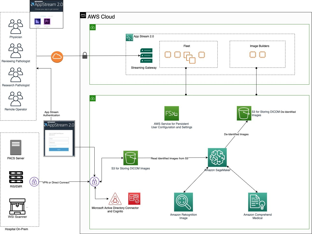
Data flow through the image management architecture
In this use case, the hospital’s on-premises systems are connected to the AWS Cloud using a private network connection, such as AWS Direct Connect, or an AWS Site-to-Site VPN. The images and files generated from the PACS server and the Electronic Medical Record (EMR) server are placed on an Amazon Simple Storage Service (Amazon S3). Amazon S3 is an object storage service that offers scalability, availability, security, and performance. All of the images and files are read from a secure S3 bucket, accessible only by the PACS. They are then de-identified and written back to a separate bucket accessible by other systems for review.
In our workflow, text-based PII is extracted from the images using Amazon Comprehend Medical. Amazon Rekognition helps to identify and detect “burned-in” PHI data (text that is actually part of the image). In addition, Amazon Rekognition can assist with entity identification within images. For example, in a batch of thousands of shoulder MRIs, Amazon Rekognition can identify a knee. Amazon SageMaker is an end-to-end machine learning platform that enables trial administrators and data management teams to prepare training data. It can also be used to build machine learning models quickly with pre-built algorithms. With Amazon SageMaker notebooks, the resulting de-identified image and text are written to the S3 bucket, and can then be used by the desktop applications.
AppStream 2.0 is a fully managed application streaming service that provides users with instant access to desktop applications from anywhere, regardless of what device is being used for access. An AppStream 2.0 image builder is used to install, add, and test your applications, and then create a software image or package. The software image contains applications that you can stream to your users. Default Windows and application settings allow your users to get started with their applications quickly. A fleet consists of fleet instances (also known as streaming instances) that run the software image that you specify. A stack consists of an associated fleet, user access policies, and storage configurations. A streaming instance (also known as a fleet instance) is an Amazon EC2 instance that is made available to a single user for application streaming.
Secure user interactions for image analysis and review
We’ve covered secure storage and anonymization of the image data that’s managed by the PACS, with images residing in Amazon S3. The next challenge is to provide secure, role-based access to those images for review by physicians, radiologists, or researchers. However, many of the applications used for image review and annotation are proprietary desktop applications that only run on specific operating systems. Traditionally, reviewers access these applications via remote desktop sessions to an on-premises workstation. This creates cost, management, network security, and data privacy concerns for the application hosts. Using Amazon AppStream 2.0, we can provide secure access to these proprietary applications in the cloud.
Authentication and access to the applications is as follows:
When end users sign in with the provided AppStream 2.0 URL, they are authenticated against Active Directory.
After the users are authenticated, the browser receives a Security Assertion Markup Language (SAML) assertion as an authentication response from Amazon Cognito, which controls access to AWS resources.
The response is then posted by the browser to the AWS sign-in SAML endpoint. Temporary security credentials are issued after the assertion and the embedded attributes are validated.
The temporary credentials are then used to create the sign-in URL.
The user is redirected to the AppStream 2.0 streaming session and is granted access permissions based on the role assigned to them. After this, they can log into the AppStream 2.0 instance and access their applications.
The application configurations are stored as persistent data using Amazon FSx, which can provide every user a unique storage drive within AppStream 2.0 streaming sessions. A user will have permissions to access only their directory. The drive is automatically mounted at the start of a streaming session. Files added or updated to the drive are automatically persisted between streaming sessions.
Figure 1. Architecture for managing, anonymizing, and analyzing medical image data
Conclusion
In our high-level use case, we reviewed how a combination of AWS services can be used to increase efficiency and reduce cost. While managing and reviewing patient data using custom applications such as PACS or image viewers, AWS services also provide an improved end user experience. This architecture provides a scalable, reliable, and secure foundation to develop your solution, leveraging the image analysis applications you already use. Your applications are available through a standard web browser, and you can manage users, access, and data with existing Active Directory group memberships and credentials.
AppStream 2.0 manages the AWS resources required to host and run your applications, scales automatically, and provides access to users on demand. AWS services can be managed using configuration as code best practices through AWS CloudFormation. CloudFormation lets you define text-based templates used to spin up cloud architectures. In a more complex setup, AWS Glue, Amazon CloudWatch, and AWS CloudTrail configured with a centralized logging account can be added to achieve 21 CFR Part 11 and GxP compliance.
For additional information, check out the following resources or contact your AWS account manager.
Customers want to use AWS services to operate on their most sensitive data, but they want to make sure that only the right people have access to that data. Even when the right people are accessing data, customers want to account for what actions those users took while accessing the data.
In this post, we show you how you can use Amazon AppStream 2.0 to grant isolated access to sensitive data and decrease your attack surface. In addition, we show you how to achieve end-to-end auditing, which is designed to provide full traceability of all activities around your data.
To demonstrate this idea, we built a sample solution that provides a data scientist with access to an Amazon SageMaker Studio notebook using AppStream 2.0. The solution deploys a new Amazon Virtual Private Cloud (Amazon VPC) with isolated subnets, where the SageMaker notebook and AppStream 2.0 instances are set up.
Why AppStream 2.0?
AppStream 2.0 is a fully-managed, non-persistent application and desktop streaming service that provides access to desktop applications from anywhere by using an HTML5-compatible desktop browser.
Each time you launch an AppStream 2.0 session, a freshly-built, pre-provisioned instance is provided, using a prebuilt image. As soon as you close your session and the disconnect timeout period is reached, the instance is terminated. This allows you to carefully control the user experience and helps to ensure a consistent, secure environment each time. AppStream 2.0 also lets you enforce restrictions on user sessions, such as disabling the clipboard, file transfers, or printing.
These features make AppStream 2.0 uniquely suitable for environments that require high security and isolation.
Why SageMaker?
Developers and data scientists use SageMaker to build, train, and deploy machine learning models quickly. SageMaker does most of the work of each step of the machine learning process to help users develop high-quality models. SageMaker access from within AppStream 2.0 provides your data scientists and analysts with a suite of common and familiar data-science packages to use against isolated data.
Solution architecture overview
This solution allows a data scientist to work with a data set while connected to an isolated environment that doesn’t have an outbound path to the internet.
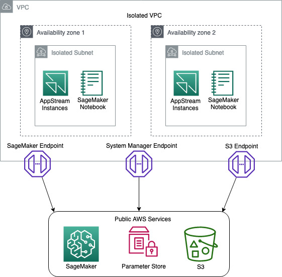
First, you build an Amazon VPC with isolated subnets and with no internet gateways attached. This ensures that any instances stood up in the environment don’t have access to the internet. To provide the resources inside the isolated subnets with a path to commercial AWS services such as Amazon S3, SageMaker, AWS System Manager you build VPC endpoints and attach them to the VPC, as shown in Figure 1.
Figure 1: Network Diagram
You then build an AppStream 2.0 stack and fleet, and attach a security group and IAM role to the fleet. The purpose of the IAM role is to provide the AppStream 2.0 instances with access to downstream AWS services such as Amazon S3 and SageMaker. The IAM role design follows the least privilege model, to ensure that only the access required for each task is granted.
During the building of the stack, you will enable AppStream 2.0 Home Folders. This feature builds an S3 bucket where users can store files from inside their AppStream 2.0 session. The bucket is designed with a dedicated prefix for each user, where only they have access. We use this prefix to store the user’s pre-signed SagaMaker URLs, ensuring that no one user can access another users SageMaker Notebook.
You then deploy a SageMaker notebook for the data scientist to use to access and analyze the isolated data.
To confirm that the user ID on the AppStream 2.0 session hasn’t been spoofed, you create an AWS Lambda function that compares the user ID of the data scientist against the AppStream 2.0 session ID. If the user ID and session ID match, this indicates that the user ID hasn’t been impersonated.
Once the session has been validated, the Lambda function generates a pre-signed SageMaker URL that gives the data scientist access to the notebook.
Finally, you enable AppStream 2.0 usage reports to ensure that you have end-to-end auditing of your environment.
To help you easily deploy this solution into your environment, we’ve built an AWS Cloud Development Kit (AWS CDK) application and stacks, using Python. To deploy this solution, you can go to the Solution deployment section in this blog post.
Note: this solution was built with all resources being in a single AWS Region. The support of multi Region is possible but isn’t part of this blog post.
Solution requirements
Before you build a solution, you must know your security requirements. The solution in this post assumes a set of standard security requirements that you typically find in an enterprise environment:
IAM policies follow the least privilege model so that only the required access is granted.
Windows clipboard, file transfer, and printing to local devices is prohibited.
Auditing and traceability of all activities is required.
Note: before you will be able to integrate SAML with AppStream 2.0, you will need to follow the AppStream 2.0 Integration with SAML 2.0 guide. There are quite a few steps and it will take some time to set up. SAML authentication is optional, however. If you just want to prototype the solution and see how it works, you can do that without enabling SAML integration.
Solution components
This solution uses the following technologies:
Amazon VPC – provides an isolated network where the solution will be deployed.
VPC endpoints – provide access from the isolated network to commercial AWS services such as Amazon S3 and SageMaker.
AWS Systems Manager – stores parameters such as S3 bucket names.
AppStream 2.0 – provides hardened instances to run the solution on.
AppStream 2.0 home folders – store users’ session information.
Amazon S3 – stores application scripts and pre-signed SageMaker URLs.
SageMaker notebook – provides data scientists with tools to access the data.
AWS Lambda – runs scripts to validate the data scientist’s session, and generates pre-signed URLs for the SageMaker notebook.
AWS CDK – deploys the solution.
PowerShell – processes scripts on AppStream 2.0 Microsoft Windows instances.
Solution high-level design and process flow
The following figure is a high-level depiction of the solution and its process flow.
Figure 2: Solution process flow
The process flow—illustrated in Figure 2—is:
A data scientist clicks on an AppStream 2.0 federated or a streaming URL.
If it’s a federated URL, the data scientist authenticates using their corporate credentials, as well as MFA if required.
If it’s a streaming URL, no further authentication is required.
The data scientist is presented with a PowerShell application that’s been made available to them.
After starting the application, it starts the PowerShell script on an AppStream 2.0 instance.
The script then:
Downloads a second PowerShell script from an S3 bucket.
Stores the variables in the session.json file and copies the file to the home folder of the session on Amazon S3.
The PUT event of the JSON file into the Amazon S3 bucket triggers an AWS Lambda function that performs the following:
Reads the session.json file from the user’s home folder on Amazon S3.
Performs a describe action against the AppStream 2.0 API to ensure that the session ID and the user ID match. This helps to prevent the user from manipulating the local environment variable to pretend to be someone else (spoofing), and potentially gain access to unauthorized data.
If the session ID and user ID match, a pre-signed SageMaker URL is generated and stored in session_url.txt, and copied to the user’s home folder on Amazon S3.
If the session ID and user ID do not match, the Lambda function ends without generating a pre-signed URL.
When the PowerShell script detects the session_url.txt file, it opens the URL, giving the user access to their SageMaker notebook.
Code structure
To help you deploy this solution in your environment, we’ve built a set of code that you can use. The code is mostly written in Python and for the AWS CDK framework, and with an AWS CDK application and some PowerShell scripts.
Note: We have chosen the default settings on many of the AWS resources our code deploys. Before deploying the code, you should conduct a thorough code review to ensure the resources you are deploying meet your organization’s requirements.
AWS CDK application – ./app.py
To make this application modular and portable, we’ve structured it in separate AWS CDK nested stacks:
vpc-stack – deploys a VPC with two isolated subnets, along with three VPC endpoints.
s3-stack – deploys an S3 bucket, copies the AppStream 2.0 PowerShell scripts, and stores the bucket name in an SSM parameter.
appstream-stack – deploys the AppStream 2.0 stack and fleet, along with the required IAM roles and security groups.
appstream-start-fleet-stack – builds a custom resource that starts the AppStream 2.0 fleet.
notebook-stack – deploys a SageMaker notebook, along with IAM roles, security groups, and an AWS Key Management Service (AWS KMS) encryption key.
saml-stack – deploys a SAML role as a placeholder for SAML authentication.
PowerShell scripts
The solution uses the following PowerShell scripts inside the AppStream 2.0 instances:
sagemaker-notebook-launcher.ps1 – This script is part of the AppStream 2.0 image and downloads the sagemaker-notebook.ps1 script.
sagemaker-notebook.ps1 – starts the process of validating the session and generating the SageMaker pre-signed URL.
Note: Having the second script reside on Amazon S3 provides flexibility. You can modify this script without having to create a new AppStream 2.0 image.
Deployment Prerequisites
To deploy this solution, your deployment environment must meet the following prerequisites:
(Optional) A SAML federation solution that’s tied to your corporate directory.
Note: We used AWS Cloud9 with Amazon Linux 2 to test this solution, as it comes preinstalled with most of the prerequisites for deploying this solution.
Deploy the solution
Now that you know the design and components, you’re ready to deploy the solution.
Note: In our demo solution, we deploy two stream.standard.small AppStream 2.0 instances, using Windows Server 2019. This gives you a reasonable example to work from. In your own environment you might need more instances, a different instance type, or a different version of Windows. Likewise, we deploy a single SageMaker notebook instance of type ml.t3.medium. To change the AppStream 2.0 and SageMaker instance types, you will need to modify the stacks/data_sandbox_appstream.py and stacks/data_sandbox_notebook.py respectively.
Step 1: AppStream 2.0 image
An AppStream 2.0 image contains applications that you can stream to your users. It’s what allows you to curate the user experience by preconfiguring the settings of the applications you stream to your users.
Note: In Step 1: Install Applications on the Image Builder in this tutorial, you will be asked to choose an Instance family. For this example, we chose General Purpose. If you choose a different Instance family, you will need to make sure the appstream_instance_type specified under Step 2: Code modification is of the same family.
In Step 6: Finish Creating Your Image in this tutorial, you will be asked to provide a unique image name. Note down the image name as you will need it in Step 2 of this blog post.
Copy notebook-launcher.ps1 to a location on the image. We recommend that you copy it to C:\AppStream.
In Step 2—Create an AppStream 2.0 Application Catalog—of the tutorial, use C:\Windows\System32\Windowspowershell\v1.0\powershell.exe as the application, and the path to notebook-launcher.ps1 as the launch parameter.
Note: While testing your application during the image building process, the PowerShell script will fail because the underlying infrastructure is not present. You can ignore that failure during the image building process.
Step 2: Code modification
Next, you must modify some of the code to fit your environment.
Make the following changes in the cdk.json file:
vpc_cidr – Supply your preferred CIDR range to be used for the VPC.
Note: VPC CIDR ranges are your private IP space and thus can consist of any valid RFC 1918 range. However, if the VPC you are planning on using for AppStream 2.0 needs to connect to other parts of your private network (on premise or other VPCs), you need to choose a range that does not conflict or overlap with the rest of your infrastructure.
appstream_Image_name – Enter the image name you chose when you built the Appstream 2.0 image in Step 1.a.
appstream_environment_name – The environment name is strictly cosmetic and drives the naming of your AppStream 2.0 stack and fleet.
appstream_instance_type – Enter the AppStream 2.0 instance type. The instance type must be part of the same instance family you used in Step 1 of the To build an AppStream 2.0 image section. For a list of AppStream 2.0 instances, visit https://aws.amazon.com/appstream2/pricing/.
appstream_fleet_type – Enter the fleet type. Allowed values are ALWAYS_ON or ON_DEMAND.
Idp_name – If you have integrated SAML with this solution, you will need to enter the IdP name you chose when creating the SAML provider in the IAM Console.
Step 3: Deploy the AWS CDK application
The CDK application deploys the CDK stacks.
The stacks include:
VPC with isolated subnets
VPC Endpoints for S3, SageMaker, and Systems Manager
S3 bucket
AppStream 2.0 stack and fleet
Two AppStream 2.0 stream.standard.small instances
A single SageMaker ml.t2.medium notebook
Run the following commands to deploy the AWS CDK application:
After the stack has successfully deployed, allow approximately 25 minutes for the AppStream 2.0 fleet to reach a running state. Testing will fail if the fleet isn’t running.
Without SAML
If you haven’t added SAML authentication, use the following steps to test the solution.
Enter the URL in another tab of your browser and test your application.
With SAML
If you are using SAML authentication, you will have a federated login URL that you need to visit.
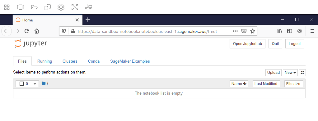
If everything is working, your SageMaker notebook will be launched as shown in Figure 3.
Figure 3: SageMaker Notebook
Note: if you receive a web browser timeout, verify that the SageMaker notebook instance “Data-Sandbox-Notebook” is currently in InService status.
Auditing
Auditing for this solution is provided through AWS CloudTrail and AppStream 2.0 Usage Reports. Though CloudTrail is enabled by default, to collect and store the CloudTrail logs, you must create a trail for your AWS account.
The following logs will be available for you to use, to provide auditing.
To get an accurate idea of your users’ activity, you have to correlate some logs from different services. First, you collect the login information from CloudTrail. This gives you the user ID of the user who logged in. You then collect the Amazon S3 put from CloudTrail, which gives you the IP address of the AppStream 2.0 instance. And finally, you collect the AppStream 2.0 usage report which gives you the IP address of the AppStream 2.0 instance, plus the user ID. This allows you to connect the user ID to the activity on Amazon S3. For auditing & controlling exploration activities with SageMaker, please visit this GitHub repository.
Though the logs are automatically being collected, what we have shown you here is a manual way of sifting through those logs. For a more robust solution on querying and analyzing CloudTrail logs, visit Querying AWS CloudTrail Logs.
Costs of this Solution
The cost for running this solution will depend on a number of factors like the instance size, the amount of data you store, and how many hours you use the solution. AppStream 2.0 is charged per instance hour and there is one instance in this example solution. You can see details on the AppStream 2.0 pricing page. VPC endpoints are charged by the hour and by how much data passes through them. There are three VPC endpoints in this solution (S3, System Manager, and SageMaker). VPC endpoint pricing is described on the Privatelink pricing page. SageMaker Notebooks are charged based on the number of instance hours and the instance type. There is one SageMaker instance in this solution, which may be eligible for free tier pricing. See the SageMaker pricing page for more details. Amazon S3 storage pricing depends on how much data you store, what kind of storage you use, and how much data transfers in and out of S3. The use in this solution may be eligible for free tier pricing. You can see details on the S3 pricing page.
Congratulations! You have deployed a solution that provides your users with access to sensitive and isolated data in a secure manner using AppStream 2.0. You have also implemented a mechanism that is designed to prevent user impersonation, and enabled end-to-end auditing of all user activities.
Amazon AppStream 2.0 is a fully managed service that lets you stream applications and desktops to your users. In this post, I’ll show you how to record a video of AppStream 2.0 streaming sessions by using FFmpeg, a popular media framework.
There are many use cases for session recording, such as auditing administrative access, troubleshooting user issues, or quality assurance. For example, you could publish administrative tools with AppStream 2.0, such as a Remote Desktop Protocol (RDP) client, to protect access to your backend systems (see How to use Amazon AppStream 2.0 to reduce your bastion host attack surface) and you may want to record a video of what your administrators do when accessing and operating backend systems. You may also want to see what a user did to reproduce an issue, or view activities in a call center setting, such as call handling or customer support, for review and training.
This solution is not designed or intended for people surveillance, or for the collection of evidence for legal proceedings. You are responsible for complying with all applicable laws and regulations when using this solution.
Overview and architecture
In this section, you can learn about the steps for recording AppStream 2.0 streaming sessions and see an overview of the solution architecture. Later in this post, you can find instructions about how to implement and test the solution.
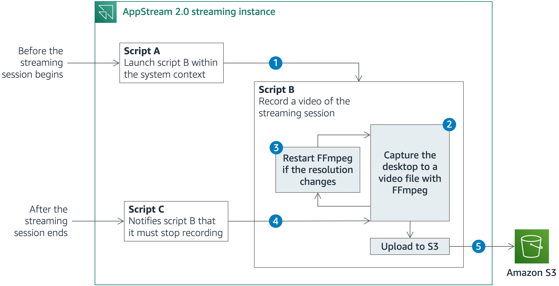
AppStream 2.0 enables you to run custom scripts to prepare the streaming instance before the applications launch or after the streaming session has completed. Figure 1 shows a simplified description of what happens before, during and after a streaming session.
Figure 1: Solution architecture
Before the streaming session starts, AppStream 2.0 runs script A, which uses PsExec, a utility that enables administrators to run commands on local or remote computers, to launch script B. Script B then runs during the entire streaming session. PsExec can run the script as the LocalSystem account, a service account that has extensive privileges on a local system, while it interacts with the desktop of another session. Using the LocalSystem account, you can use FFmpeg to record the session screen and prevent AppStream 2.0 users from stopping or tampering with the solution, as long as they aren’t granted local administrator rights.
Script B launches FFmpeg and starts recording the desktop. The solution uses the FFmpeg built-in screen-grabber to capture the desktop across all the available screens.
When FFmpeg starts recording, it captures the area covered by the desktop at that time. If the number of screens or the resolution changes, a portion of the desktop might be outside the recorded area. In that case, script B stops the recording and starts FFmpeg again.
After the streaming session ends, AppStream 2.0 runs script C, which notifies script B that it must end the recording and close. Script B stops FFmpeg.
For a more comprehensive understanding of how the session scripts works, you can refer to the GitHub repository that contains the solution artifacts, where I go into the details of each script.
Implementing and testing the solution
Now that you understand the architecture of this solution, you can follow the instructions in this section to implement this blog post’s solution in your AWS account. You will:
Configure the solution scripts on the image builder.
Specify an application to publish and create an image.
Create an AppStream 2.0 fleet.
Create an AppStream 2.0 stack.
Create a user in the AppStream 2.0 user pool.
Launch a streaming session and test the solution.
Step 1: Create a VPC, an S3 bucket, and an IAM role with AWS CloudFormation
For the first step in the solution, you create a new VPC where AppStream 2.0 will be deployed, or choose an existing VPC, a new S3 bucket to store the session recordings, and a new IAM role to grant AppStream 2.0 the necessary IAM permissions.
To create the VPC, the S3 bucket, and the IAM role with AWS CloudFormation
Select the following Launch Stack button to open the CloudFormation console and create a CloudFormation stack from the template. You can change the Region where resources are deployed in the navigation bar.
The latest template can also be downloaded on GitHub.
Choose Next. For VPC ID, Subnet 1 ID and Subnet 2 ID, you can optionally select a VPC and two subnets, if you want to deploy the solution in an existing VPC, or leave these fields blank to create a new VPC. Then follow the on-screen instructions. AWS CloudFormation creates the following resources:
(If you chose to create a new VPC) Two public subnets on this Amazon VPC with a new route table to make them publicly accessible.
An S3 bucket to store the session recordings.
An IAM role to grant AppStream 2.0 permissions to upload video and metadata files to Amazon S3.
After the stack creation has completed, choose the Outputs tab in the CloudFormation console and note the values that the process returned: the name and Region of the S3 bucket, the name of the IAM role, the ID of the VPC, and the two subnets.
Step 2: Create an AppStream 2.0 image builder
The next step is to create a new AppStream 2.0 image builder. An image builder is a virtual machine that you can use to install and configure applications for streaming, and then create a custom image.
To create the AppStream 2.0 image builder
Open the AppStream 2.0 console and select the Region in the navigation bar. Choose Get Started then Skip if you are new to the console.
Choose Images in the left pane, and then choose Image Builder. Choose Launch Image Builder.
In Step 1: Choose Image:
Select the name of the latest AppStream 2.0 base image for the Windows Server version of your choice. You can find its name in the AppStream 2.0 base image version history. For example, at the time of writing, the name of the latest Windows Server 2019 base image is AppStream-WinServer2019-07-16-2020.
Choose Next.
In Step 2: Configure Image Builder:
For Name, enter session-recording.
For Instance Type, choose stream.standard.medium.
For IAM role, select the IAM role that AWS CloudFormation created.
Choose Next.
In Step 3: Configure Network:
Choose Default Internet Access to provide internet access to your image builder.
For VPC, select the ID of the VPC, and for Subnet 1, select the ID of Subnet 1.
For Security group(s), select the ID of the security group. Refer back to the Outputs tab of the CloudFormation stack if you are unsure which VPC, subnet and security group to select.
Choose Review.
In Step 4: Review, choose Launch.
Step 3: Configure the solution scripts on the image builder
The session scripts to run before streaming sessions start or after sessions end are specified within an AppStream 2.0 image. In this step, you install the solution scripts on your image builder and specify the scripts to run in the session scripts configuration file.
To configure the solution scripts on the image builder
Wait until the image builder is in the Running state, and then choose Connect.
Within the AppStream 2.0 streaming session, on the Local User tab, choose Administrator.
To install the solution scripts:
From the image builder desktop, choose Start in the Windows taskbar.
Open the context (right-click) menu for Windows PowerShell, and then choose Run as Administrator.
Run the following commands in the PowerShell terminal to create the required folders, and to copy the solution scripts and the session scripts configuration file from public objects in GitHub to the local disk. If you aren’t using Google Chrome or the AppStream 2.0 client, you need to choose the Clipboard icon in the AppStream 2.0 navigation bar, and then select Paste to remote session.
To edit the variables.ps1 file with your own values:
From the image builder desktop, choose Start in the Windows taskbar.
Open the context (right-click) menu for Windows PowerShell ISE, and then choose Run as Administrator.
Choose File, then Open. Navigate to the folder C:\SessionRecording\Scripts\ and open the file variables.ps1.
Edit the name and the Region of the S3 bucket with the values returned by AWS CloudFormation in the Outputs tab. You can also customize the number of frames per second, and the maximum duration in seconds of each video file. Save the file.
Save and close the file.
To download the latest FFmpeg and PsExec executables to the image builder:
From the image builder desktop, open the Firefox desktop icon.
Navigate to the URL https://www.gyan.dev/ffmpeg/builds/ffmpeg-release-github and choose the link that contains essentials_build.zip to download FFmpeg. Choose Open to download and extract the ZIP archive. Copy the file ffmpeg.exe in the bin folder of the ZIP archive to C:\SessionRecording\Bin\.
Note: FFmpeg only provides source code and compiled packages are available at third-party locations. If the link above is invalid, go to the FFmpeg download page and follow the instructions to download the latest release build for Windows.
Navigate to the URL https://download.sysinternals.com/files/PSTools.zip to download PsExec. Choose Open to download and extract the ZIP archive. Copy the file PsExec64.exe to C:\SessionRecording\Bin\. You must agree with the license terms, because the solution in this blog post automatically accepts them.
Close Firefox.
Step 4: Specify an application to publish and create an image
In this step, you publish Firefox on your image builder and create an AppStream 2.0 custom image. I chose Firefox because it’s easy to test later in the procedure. You can choose other or additional applications to publish, if needed.
To specify the application to publish and create the image
From the image builder desktop, open the Image Assistant icon available on the desktop. Image Assistant guides you through the image creation process.
In 1. Add Apps:
Choose + Add App.
Enter the location C:\Program Files (x86)\Mozilla Firefox\firefox.exe to add Firefox.
Choose Open. Keep the default settings and choose Save.
Choose Next multiple times until you see 4. Optimize.
In 4. Optimize:
Choose Launch.
Choose Continue until you can see 5. Configure Image.
In 5. Configure Image:
For Name, enter session-recording for your image name.
Choose Next.
In 6. Review:
Choose Disconnect and Create Image.
Back in the AppStream 2.0 console:
Choose Images in the left pane, and then choose the Image Registry tab.
Change All Images to Private and shared with others. You will see your new AppStream 2.0 image.
Wait until the image is in the Available state. This can take more than 30 minutes.
Step 5: Create an AppStream 2.0 fleet
Next, create an AppStream 2.0 fleet that consists of streaming instances that run your custom image.
To create the AppStream 2.0 fleet
In the left pane of the AppStream 2.0 console, choose Fleets, and then choose Create Fleet.
In Step 1: Provide Fleet Details:
For Name, enter session-recording-fleet.
Choose Next.
In Step 2: Choose an Image:
Select the name of the custom image that you created with the image builder.
Choose Next.
In Step 3: Configure Fleet:
For Instance Type, select stream.standard.medium.
For Fleet Type, choose Always-on.
For Stream view, you can choose to stream either the applications or the entire desktop.
For IAM role, select the IAM role.
Keep the defaults for all other parameters, and choose Next.
In Step 4: Configure Network:
Choose Default Internet Access to provide internet access to your image builder.
Select the VPC, the two subnets, and the security group.
Choose Next.
In Step 5: Review, choose Create.
Wait until the fleet is in the Running state.
Step 6: Create an AppStream 2.0 stack
Create an AppStream 2.0 stack and associate it with the fleet that you just created.
To create the AppStream 2.0 stack
In the left pane of the AppStream 2.0 console, choose Stacks, and then choose Create Stack.
In Step 1: Stack Details:
For Name, enter session-recording-stack.
For Fleet, select the fleet that you created.
Then follow the on-screen instructions and keep the defaults for all other parameters until the stack is created.
Step 7: Create a user in the AppStream 2.0 user pool
The AppStream 2.0 user pool provides a simplified way to manage access to applications for your users. In this step, you create a user in the user pool that you will use later in the procedure to test the solution.
To create the user in the AppStream 2.0 user pool
In the left pane of the AppStream 2.0 console, choose User Pool, and then choose Create User.
Enter your email address, first name, and last name. Choose Create User.
Select the user you just created. Choose Actions, and then choose Assign stack.
Select the stack, and then choose Assign stack.
Step 8: Test the solution
Now, sign in to AppStream 2.0 with the user that you just created, launch a streaming session, and check that the session recordings are delivered to Amazon S3.
To launch a streaming session and test the solution
AppStream 2.0 sends you a notification email. Connect to the sign in portal by entering the information included in the notification email, and set a permanent password.
Sign in to AppStream 2.0 by entering your email address and the permanent password.
After you sign in, you can view the application catalog. Choose Firefox to launch a Firefox window and browse any websites you’d like.
Choose the user icon at the top-right corner, and then choose Logout to end the session.
In the Amazon S3 console, navigate to the S3 bucket to browse the session recordings. For the session you just terminated, you can find one text file that contains user and instance metadata, and one or more video files that you can download and play with a media player like VLC.
Step 9: Clean up resources
You can now delete the two CloudFormation stacks to clean up the resources that were just created.
To clean up resources
To delete the image builder:
In the left pane of the AppStream 2.0 console, choose Images, and then choose Image Builder.
Select the image builder. Choose Actions, then choose Delete.
To delete the stack:
In the left pane of the AppStream 2.0 console, choose Stacks.
Select the image builder. Choose Actions, then choose Disassociate Fleet. Choose Disassociate to confirm.
Choose Actions, then choose Delete.
To delete the fleet:
In the left pane of the AppStream 2.0 console, choose Fleets.
Select the fleet. Choose Actions, then choose Stop. Choose Stop to confirm.
Wait until the fleet is in the Stopped state.
Choose Actions, then choose Delete.
To disable the user in the user pool:
In the left pane of the AppStream 2.0 console, choose User Pool.
Select the user. Choose Actions, then choose Disable user. Choose Disable User to confirm.
Empty the S3 bucket that CloudFormation created (see How do I empty an S3 bucket?). Repeat the same operation with the buckets that AppStream 2.0 created, whose names start with appstream-settings, appstream-logs and appstream2.
In this blog post, I showed you a way to record AppStream 2.0 sessions to video files for administrative access auditing, troubleshooting, or quality assurance. While this blog post focuses on Amazon AppStream 2.0, you could adapt and deploy the solution in Amazon Workspaces or in Amazon Elastic Compute Cloud (Amazon EC2) Windows instances.
For a deep-dive explanation of how the solution scripts function, you can refer to the GitHub repository that contains the solution artifacts.
If you have feedback about this post, submit comments in the Comments section below. If you have questions about this post, start a new thread on the Amazon AppStream 2.0 forum or contact AWS Support.
Want more AWS Security how-to content, news, and feature announcements? Follow us on Twitter.
The collective thoughts of the interwebz
Manage Consent
To provide the best experiences, we use technologies like cookies to store and/or access device information. Consenting to these technologies will allow us to process data such as browsing behavior or unique IDs on this site. Not consenting or withdrawing consent, may adversely affect certain features and functions.
Functional
Always active
The technical storage or access is strictly necessary for the legitimate purpose of enabling the use of a specific service explicitly requested by the subscriber or user, or for the sole purpose of carrying out the transmission of a communication over an electronic communications network.
Preferences
The technical storage or access is necessary for the legitimate purpose of storing preferences that are not requested by the subscriber or user.
Statistics
The technical storage or access that is used exclusively for statistical purposes.The technical storage or access that is used exclusively for anonymous statistical purposes. Without a subpoena, voluntary compliance on the part of your Internet Service Provider, or additional records from a third party, information stored or retrieved for this purpose alone cannot usually be used to identify you.
Marketing
The technical storage or access is required to create user profiles to send advertising, or to track the user on a website or across several websites for similar marketing purposes.