Post Syndicated from Channy Yun (윤석찬) original https://aws.amazon.com/blogs/aws/aws-weekly-roundup-mithra-amazon-titan-image-generator-v2-aws-genai-lofts-and-more-august-12-2024/
When Dr. Swami Sivasubramanian, VP of AI and Data, was an intern at Amazon in 2005, Dr. Werner Vogels, CTO of Amazon, was his first manager. Nineteen years later, the two shared a stage at the VivaTech Conference to reflect on Amazon’s history of innovation—from pioneering the pay-as-you-go model with Amazon Web Services (AWS) to transforming customer experiences using “good old-fashioned AI”—as well as what really keeps them up at night in the age of generative artificial intelligence (generative AI).

Asked if competitors ever kept him up at night, Dr. Werner insisted that listening to customer needs—such as guardrails, security, and privacy—and building products based on those needs is what drives success at Amazon. Dr. Swami said he viewed Amazon SageMaker and Amazon Bedrock as prime examples of successful products that have emerged as a result of this customer-first approach. “If you end up chasing your competitors, you are going to end up building what they are building,” he added. “If you actually listen to your customers, you are actually going to lead the way in innovation.” To learn four more lessons on customer-obsessed innovation, visit our AWS Careers blog.
 For example, for customer-obsessed security, we build and use Mithra, a powerful neural network model to detect and respond to cyber threats. It analyzes up to 200 trillion internet domain requests daily from the AWS global network, identifying an average of 182,000 new malicious domains with remarkable accuracy. Mithra is just one example of how AWS uses global scale, advanced artificial intelligence and machine learning (AI/ML) technology, and constant innovation to lead the way in cloud security, making the internet safer for everyone. To learn more, visit the blog post of Chief Information Security Officer at Amazon CJ Moses, How AWS tracks the cloud’s biggest security threats and helps shut them down.
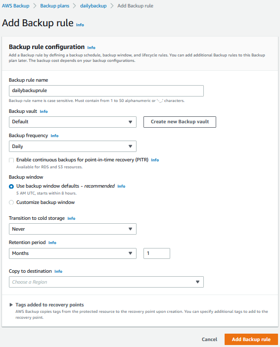
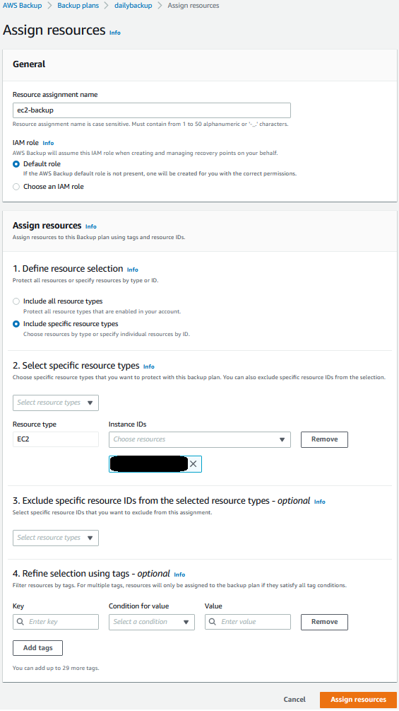
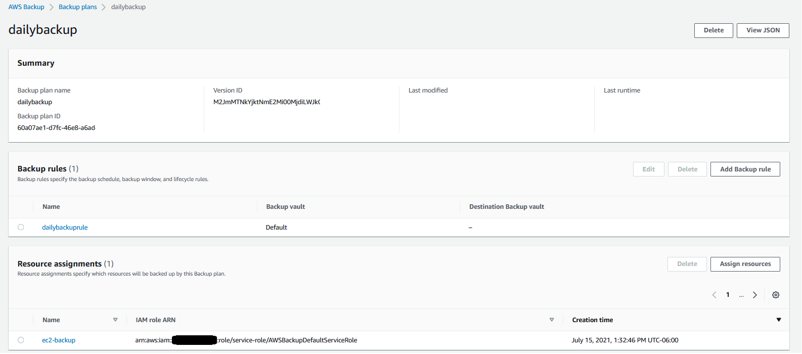
Last week’s launches
Here are some launches that got my attention:
Amazon Titan Image Generator v2 in Amazon Bedrock – With the new Amazon Titan Image Generator v2 model, you can guide image creation using a text prompt and reference images, control the color palette of generated images, remove backgrounds, and customize the model to maintain brand style and subject consistency. To learn more, visit my blog post, Amazon Titan Image Generator v2 is now available in Amazon Bedrock.
Regional expansion of Anthropic’s Claude models in Amazon Bedrock – The Claude 3.5 Sonnet, Anthropic’s latest high-performance AI model, is now available in US West (Oregon), Europe (Frankfurt), Asia Pacific (Tokyo), and Asia Pacific (Singapore) Regions in Amazon Bedrock. The Claude 3 Haiku, Anthropic’s compact and affordable AI model, is now available in Asia Pacific (Tokyo) and Asia Pacific (Singapore) Regions in Amazon Bedrock.
Private IPv6 addressing for VPCs and subnets – You can now address private IPv6 for VPCs and subnets with Amazon VPC IP Address Manager (IPAM). Within IPAM, you can configure private IPv6 addresses in a private scope, provision Unique Local IPv6 Unicast Addresses (ULA) and Global Unicast Addresses (GUA), and use them to create VPCs and subnets for private access. To learn more, visit see the Understanding IPv6 addressing on AWS and designing a scalable addressing plan and VPC documentation,
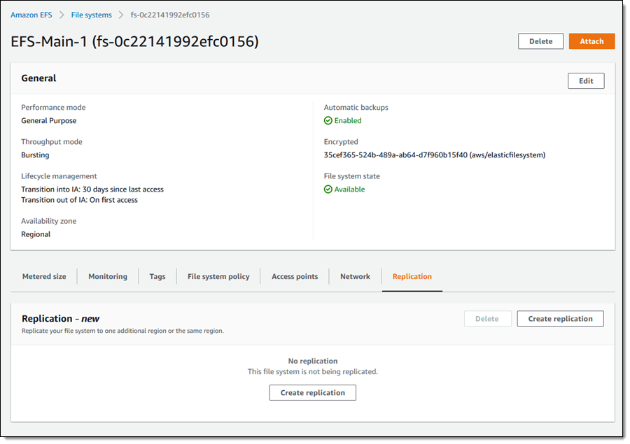
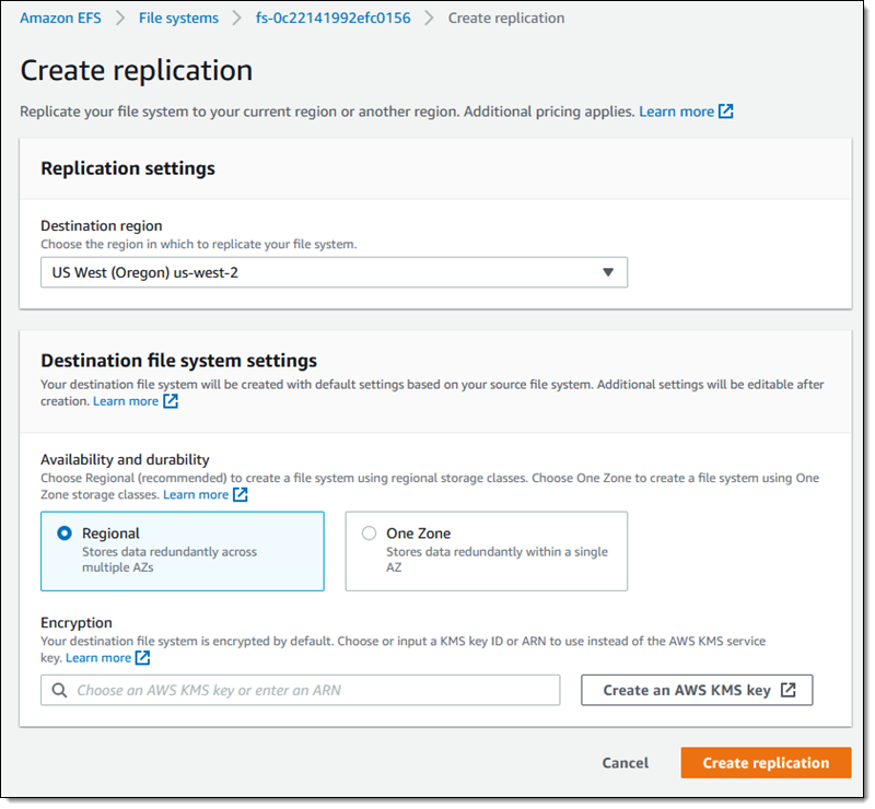
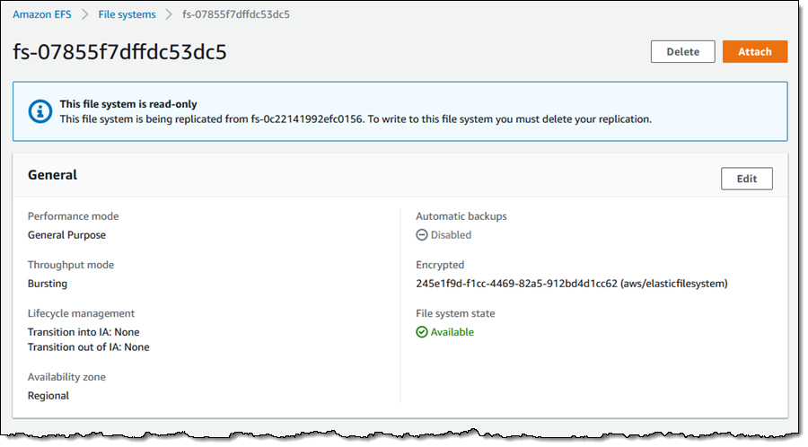
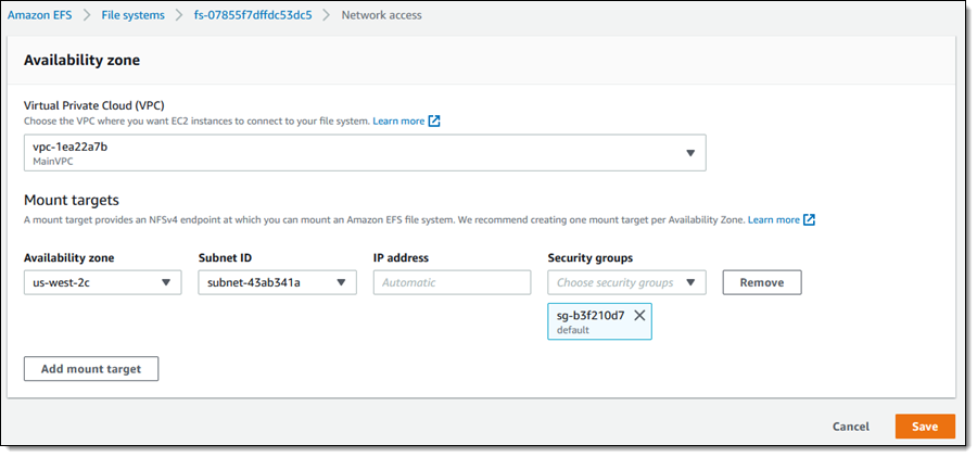
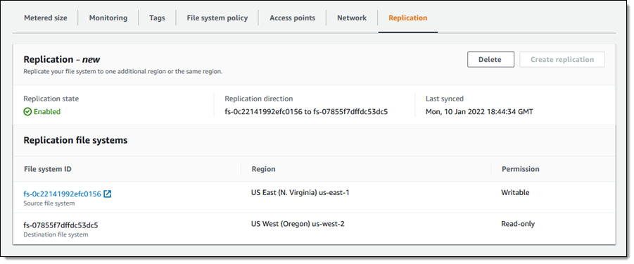
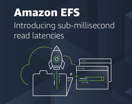
Up to 30 GiB/s of read throughput in Amazon EFS – We are increasing the read throughput to 30 GiB/s, extending simple, fully elastic, and provisioning-free experience of Amazon EFS to support throughput-intensive AI and ML workloads for model training, inference, financial analytics, and genomic data analysis.
Large language models (LLMs) in Amazon Redshift ML – You can use pre-trained publicly available LLMs in Amazon SageMaker JumpStart as part of Amazon Redshift ML. For example, you can use LLMs to summarize feedback, perform entity extraction, and conduct sentiment analysis on data in your Amazon Redshift table, so you can bring the power of generative AI to your data warehouse.
Data products in Amazon DataZone – You can create data products in Amazon DataZone, which enable the grouping of data assets into well-defined, self-contained packages tailored for specific business use cases. For example, a marketing analysis data product can bundle various data assets such as marketing campaign data, pipeline data, and customer data. To learn more, visit this AWS Big Data blog post.
For a full list of AWS announcements, be sure to keep an eye on the What’s New at AWS page.
Other AWS news
Here are some additional news items that you might find interesting:
AWS Goodies by Jeff Barr – Want to discover more exciting news about AWS? Jeff Barr is always in catch-up mode, doing his best to share all of the interesting things that he finds or that are shared with him. You can find his goodies once a week. Follow his LinkedIn page.
AWS and Multicloud – You might have missed a great article about the existing capabilities AWS has and the continued enhancements we’ve made in multicloud environments. In the post, Jeff covers the AWS approach to multicloud, provides you with some real-world examples, and reviews some of the newest multicloud and hybrid capabilities found across the lineup of AWS services.
Code transformation in Amazon Q Developer – At Amazon, we asked a small team to use Amazon Q Developer Agent for code transformation to migrate more than 30,000 production applications from older Java versions to Java 17. By using Amazon Q Developer to automate these upgrades, the team saved over 4,500 developer years of effort compared to what it would have taken to do all of these upgrades manually and saved the company $260 million in annual savings by moving to the latest Java version.
![]()
Contributing to AWS CDK – AWS Cloud Development Kit (AWS CDK) is an open source software development framework to model and provision your cloud application resources using familiar programming languages. Contributing to AWS CDK not only helps you deepen your knowledge of AWS services but also allows you to give back to the community and improve a tool you rely on.
Upcoming AWS events
Check your calendars and sign up for these AWS events:
AWS re:Invent 2024 – Dive into the first-round session catalog. Explore all the different learning opportunities at AWS re:Invent this year and start building your agenda today. You’ll find sessions for all interests and learning styles.
AWS Innovate Migrate, Modernize, Build – Learn about proven strategies and practical steps for effectively migrating workloads to the AWS Cloud, modernizing applications, and building cloud-native and AI-enabled solutions. Don’t miss this opportunity to learn with the experts and unlock the full potential of AWS. Register now for Asia Pacific, Korea, and Japan (September 26).
AWS Summits – The 2024 AWS Summit season is almost wrapping up! Join free online and in-person events that bring the cloud computing community together to connect, collaborate, and learn about AWS. Register in your nearest city: São Paulo (August 15), Jakarta (September 5), and Toronto (September 11).
AWS Community Days – Join community-led conferences that feature technical discussions, workshops, and hands-on labs led by expert AWS users and industry leaders from around the world: New Zealand (August 15), Colombia (August 24), New York (August 28), Belfast (September 6), and Bay Area (September 13).
AWS GenAI Lofts – Meet AWS AI experts and attend talks, workshops, fireside chats, and Q&As with industry leaders. All lofts are free and are carefully curated to offer something for everyone to help you accelerate your journey with AI. There are lofts scheduled in San Francisco (August 14–September 27), São Paulo (September 2–November 20), London (September 30–October 25), Paris (October 8–November 25), and Seoul (November).
You can browse all upcoming in-person and virtual events.
That’s all for this week. Check back next Monday for another Weekly Roundup!
— Channy
This post is part of our Weekly Roundup series. Check back each week for a quick roundup of interesting news and announcements from AWS!


 Faster is always better, and today I am thrilled to be able to tell you that your latency-sensitive EFS workloads can now run about twice as fast as before!