Tag Archives: AWS Systems Manager

Architecting AI-powered resilience framework on AWS

Post Syndicated from Medha Shree original https://aws.amazon.com/blogs/architecture/architecting-ai-powered-resilience-framework-on-aws/

When your production system goes down, you often discover the hard way that your resilience testing missed critical dependencies. Building an AI-powered resilience framework on AWS helps you find those weaknesses before your customers do.

Your systems don’t fail because your infrastructure isn’t resilient. They fail because resilience is assumed, not proven. Every deployment introduces new dependencies, every configuration change creates untested paths, and every gap between design intent and runtime behavior is a risk waiting to surface. In a world where customers expect always-on availability, the cost of discovering these weaknesses in production isn’t just technical. It’s measured in revenue lost, trust eroded, and events that were entirely preventable.

In this post, you’ll learn how to architect and implement a five-layer AI-powered resilience framework that automatically discovers dependencies, generates targeted experiments, and integrates with your existing Continuous Integration/Continuous Deployment (CI/CD) pipelines. First, we’ll explore the key challenges in resilience testing. Then, we’ll walk through the five-layer architecture that solves these challenges. Finally, we’ll show you how to implement this, with phased rollout guidance for pilot, expansion, and organization-wide deployment.

Traditional resilience testing can take weeks because the information needed is naturally spread across architecture diagrams, runbooks, code repositories, and team knowledge that evolves with every deployment. Designing meaningful chaos experiments on top of that requires specialized expertise that most teams don’t have on hand. Here’s how this AI-powered framework discovers your infrastructure dependencies in hours and generates targeted experiments without requiring specialized knowledge.

Combining AWS Resilience Hub, AWS Fault Injection Service, Amazon Bedrock AgentCore, and AWS Systems Manager work together to discover infrastructure dependencies in hours, tailor experiments to your specific architecture, and identify weaknesses before they affect customers.

With the next generation of AWS Resilience Hub now providing native dependency discovery and generative AI-powered failure mode analysis, this framework extends those capabilities by automating experiment generation, embedding resilience testing into your CI/CD pipelines, and creating a continuous validation loop through custom AI agents hosted on Amazon Bedrock AgentCore.

Key concepts

Before diving into the architecture, here are the key terms used throughout this post:

  • Chaos engineering — The discipline of experimenting on a system to build confidence in its ability to withstand turbulent conditions in production.
  • Mean time to resolution (MTTR) — The average time to restore service after a failure.
  • Recovery Time Objective (RTO) — The maximum acceptable downtime for your application.
  • Recovery Point Objective (RPO) — The maximum acceptable data loss, measured in time.
  • Shift-left — Testing earlier in the development cycle to catch issues before they reach production.
  • Circuit breaker — An automated mechanism that detects service failures and helps prevent cascading outages by temporarily blocking requests to failing services.
  • Canary deployment — A technique where changes roll out to a small percentage of users first to validate functionality before full deployment.

Who this is for

This post targets cloud architects, DevOps engineers, and Site Reliability Engineering (SRE) teams responsible for system reliability. You should understand AWS services, distributed systems architecture, and CI/CD pipelines. While chaos engineering experience helps, it’s not required. This framework reduces the expertise barrier that traditionally prevented adoption.

Resilience testing challenges

When infrastructure changes happen quickly, documentation tends to lag behind. A routing change to the payment service might not get reflected in the architecture diagrams, leaving single points of failure (like a single-Availability Zone authentication dependency) undocumented and untested. The payment service calls a legacy authentication API that only runs in one Availability Zone, a critical single point of failure. But documentation doesn’t reflect this because someone made a “quick fix” three weeks ago and forgot to update the diagrams.

Distributed systems contain hundreds of interconnected components. Tracking every dependency manually becomes impractical when you deploy changes continuously. Documentation created last month already misses dozens of new dependencies.

Resilience testing can be challenging without dedicated specialists to design meaningful experiments. Resilience testing is most effective when it’s tailored to your actual architecture and runs continuously. Generic fault injection and one-off test runs can leave gaps, especially as your system changes over time.

The expertise barrier stops many organizations entirely. Effective chaos engineering demands understanding distributed systems architecture, failure mode analysis, experiment scope management, and safe experiment design. Without this specialized knowledge, you either avoid resilience testing or run superficial tests that miss critical vulnerabilities.

According to the 2024 IBM Security Services Benchmark Report, organizations with mature response capabilities reduce their MTTR by approximately 50% and achieve cost savings of up to 58% per event when compared to organizations with less mature capabilities. Yet Gartner research shows that 68% of organizations cite increasing system complexity as their reason for adopting chaos engineering, while 50% admit they weren’t prepared when failures occurred.

This framework automates discovery. Automated discovery reduces infrastructure mapping from weeks to hours, typically completing initial assessment in 2–4 hours for single-account environments with thousands of resources. Subsequent runs process only the changes tracked by AWS Config, so your architecture map stays current without manual effort. Agents hosted on AgentCore Runtime analyze your AWS CloudFormation templates, code repositories, and runtime behavior to identify every connection, including hidden dependencies that manual audits miss. Experiment templates analyze your specific architecture and produce targeted tests that validate your actual failure modes, removing the need for specialized chaos engineering expertise. Continuous integration into your CI/CD pipelines catches regressions before they reach production, shifting resilience from a one-time project into an ongoing practice embedded in your development workflow.

Solution overview

The framework addresses these gaps by automatically discovering infrastructure dependencies and continuously validating resilience as the system changes. AI agents, hosted on AgentCore Runtime for secure, scalable execution, discover system dependencies automatically, analyze architectural patterns, and create targeted experiments based on your actual risk profiles. Testing scales across your application portfolio while lowering the expertise barrier.

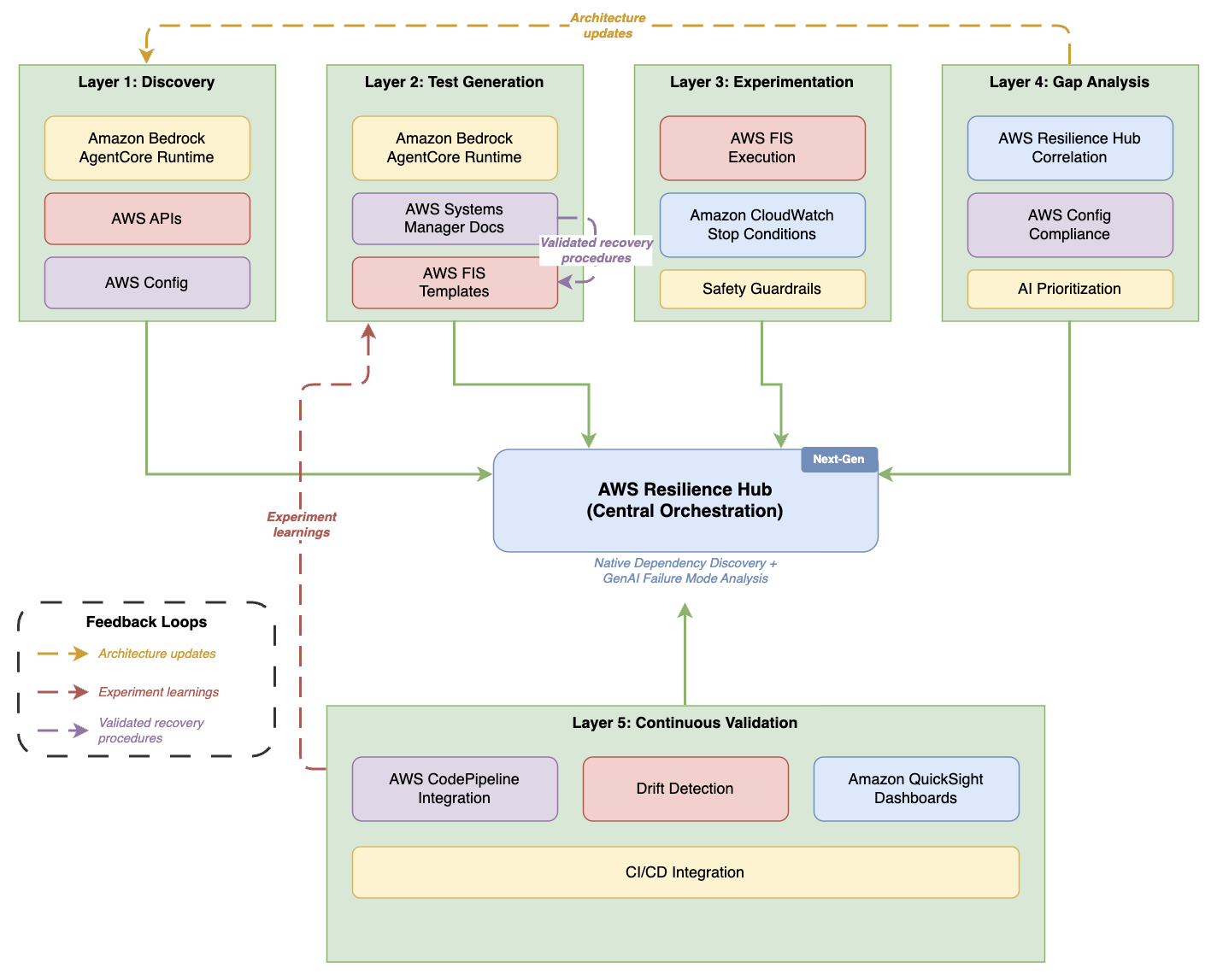
Five-layer AI-powered resilience architecture with AWS Resilience Hub as the central orchestration hub

Figure 1. Five-layer AI-powered resilience architecture

Five-layer architecture diagram with AWS Resilience Hub — labeled “Next-Gen” with native dependency discovery and generative AI failure mode analysis — as the central orchestration hub. Layers 1–4 (Discovery, Test Generation, Experimentation, Gap Analysis) sit across the top, each connecting down to the hub. Layer 5 (Continuous Validation) sits below with CI/CD, drift detection, and dashboards. Three dashed feedback loops overlay the diagram: Gap Analysis feeds “Architecture updates” back to Discovery, Continuous Validation sends “Experiment learnings” up to Test Generation, and SSM Docs feeds “Validated recovery procedures” into FIS Templates within the Test Generation layer.

Each layer builds on the previous one, creating a comprehensive validation strategy. This architecture aligns with the AWS Well-Architected Reliability Pillar, specifically the Test reliability best practice area. Discovery maps your infrastructure. Test generation creates relevant experiments from that map. Experimentation executes those tests safely. Gap analysis identifies what needs fixing. Continuous validation helps verify that improvements persist as your systems evolve.

Now that you understand the overall strategy, let’s examine each layer in detail, starting with how the discovery layer automatically maps your infrastructure.

Discovery layer

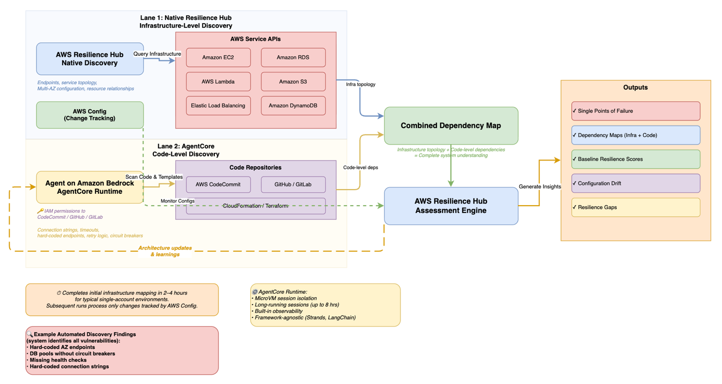
The discovery layer forms the foundation by automatically identifying infrastructure components and their dependencies. The next generation of AWS Resilience Hub provides native dependency discovery that identifies AWS services, internal endpoints, and third-party endpoints your applications rely on. A custom agent deployed on Amazon Bedrock AgentCore (with read permissions to AWS APIs) extends this native discovery with code-level analysis, scanning your code repositories for hard-coded dependencies, connection strings, timeout configurations, and retry logic that infrastructure-level discovery alone cannot detect. A custom agent deployed on Amazon Bedrock AgentCore (with read permissions to AWS APIs) handles infrastructure discovery. Amazon Bedrock AgentCore Runtime provides dedicated MicroVM session isolation, supports long-running discovery sessions up to eight hours, and handles scaling and security without requiring you to manage infrastructure. The runtime’s built-in observability (traces, logs, and metrics) integrates natively with your existing Amazon CloudWatch dashboards without additional instrumentation.

The AgentCore-hosted agent queries services including Amazon Elastic Compute Cloud (Amazon EC2), Amazon Relational Database Service (Amazon RDS), AWS Lambda, Amazon DynamoDB, and Amazon Simple Storage Service (Amazon S3) to build comprehensive inventory. It analyzes AWS CloudFormation templates and Terraform configurations to understand your intended architecture, and accesses code repositories to identify hard-coded dependencies, connection strings, and timeout configurations in your applications. AWS Config provides configuration data and tracks changes over time. This discovery completes in 2–4 hours for environments with thousands of resources.

AI-powered discovery workflow showing infrastructure-level and code-level discovery feeding into a combined dependency map

Figure 2. AI-powered discovery workflow

Workflow diagram organized in two swim lanes. Lane 1 (blue) shows AWS Resilience Hub native infrastructure-level discovery querying AWS service APIs (Amazon EC2, Amazon RDS, AWS Lambda, Amazon S3, Elastic Load Balancing, Amazon DynamoDB) for service topology, endpoints, and Multi-AZ configuration. Lane 2 (yellow) shows an agent on Amazon Bedrock AgentCore performing code-level discovery — scanning repositories (CodeCommit, GitHub, GitLab via IAM permissions) and analyzing CloudFormation/Terraform templates for connection strings, timeouts, and circuit breakers. Both lanes feed into a combined dependency map, which flows into the AWS Resilience Hub assessment engine. Outputs include single points of failure, dependency maps (infrastructure + code), baseline resilience scores, configuration drift, and resilience gaps. AWS Config monitors configurations in parallel. A dashed feedback arrow loops from the assessment engine back to the AgentCore agent labeled “Architecture updates & learnings.” Initial mapping completes in 2–4 hours for typical single-account environments; subsequent runs process only changes tracked by AWS Config.

Test generation layer

While the next generation of Resilience Hub includes a generative AI-powered failure mode assessment that identifies potential weaknesses through static analysis, this test generation layer converts those recommendations into executable AWS Fault Injection Service experiment templates, complete with safety guardrails, progressive scope expansion, and business impact scoring tailored to your specific architecture.

Building on the discovered infrastructure, the test generation layer creates targeted chaos experiments for your specific architecture. The agent hosted on AgentCore Runtime uses Amazon Bedrock foundation models to analyze your infrastructure context, combined with the RTO, RPO, and availability targets you define in AWS Resilience Hub, to identify single points of failure and produce hypothesis-driven test scenarios aligned with your business requirements. Each hypothesis is scored by potential business impact, prioritizing experiments for customer-facing systems and components where architectural patterns indicate high-availability intent. Each experiment includes business impact scoring based on your application tier definitions in AWS Resilience Hub, architectural patterns (such as internet-facing load balancers and Amazon API Gateway endpoints), dependency analysis, and AWS resource tags. This makes sure experiments prioritize your customer-facing systems and highest-impact components. Using the code repository analysis from the discovery layer, the system detects when your applications use Amazon RDS Multi-AZ but lack proper connection retry handling, and designs database failover tests that validate your actual recovery mechanisms rather than generic network disruption tests.

For your production environments, implement a manual approval workflow where your infrastructure teams review experiment templates before execution. AWS Step Functions orchestrates approval gates. Step Functions is a workflow management service that coordinates multiple AWS services into serverless workflows.

Experimentation layer

After creating targeted experiments, the experimentation layer runs chaos tests with multi-layered safety guardrails on your infrastructure. AWS Fault Injection Service executes chaos tests with built-in safety mechanisms. Experiments start with minimal scope (affecting only 1% of your resources) and expand progressively based on your risk tolerance and validation results (for example, 1% → 5% → 10% → 25%). This follows progressive deployment strategies recommended in the AWS Well-Architected Reliability Pillar, similar to canary deployments where changes roll out incrementally to limit blast radius. Amazon CloudWatch alarms serve as stop conditions that halt experiments before they violate your Service Level Agreements (SLAs), which are contracts defining expected uptime and performance. Set alarm thresholds well below your SLA limits. If your SLA allows 1% error rate, configure stop conditions to trigger at 0.1%.

Gap analysis layer

After your experiments complete, the gap analysis layer processes results to identify weaknesses and prioritize remediation. AWS Resilience Hub correlates experiment outcomes with your resilience policies, categorizing gaps across architectural, operational, data protection, and testing dimensions. Each gap receives a priority score based on severity (how badly this violates your resilience policy), likelihood (how often this failure mode occurs), and business impact (the cost if this failure occurs in your environment).

Continuous validation layer

The continuous validation layer integrates resilience testing into your development workflow. The right approach depends on your deployment velocity and testing goals.

For most teams, a lightweight policy-as-code check (using tools like Open Policy Agent to validate Infrastructure as Code and Dockerfiles) runs in seconds and fits naturally in your CI/CD pipeline for every commit. This catches basic configuration issues, like missing health checks or single-AZ deployments, before code reaches staging.

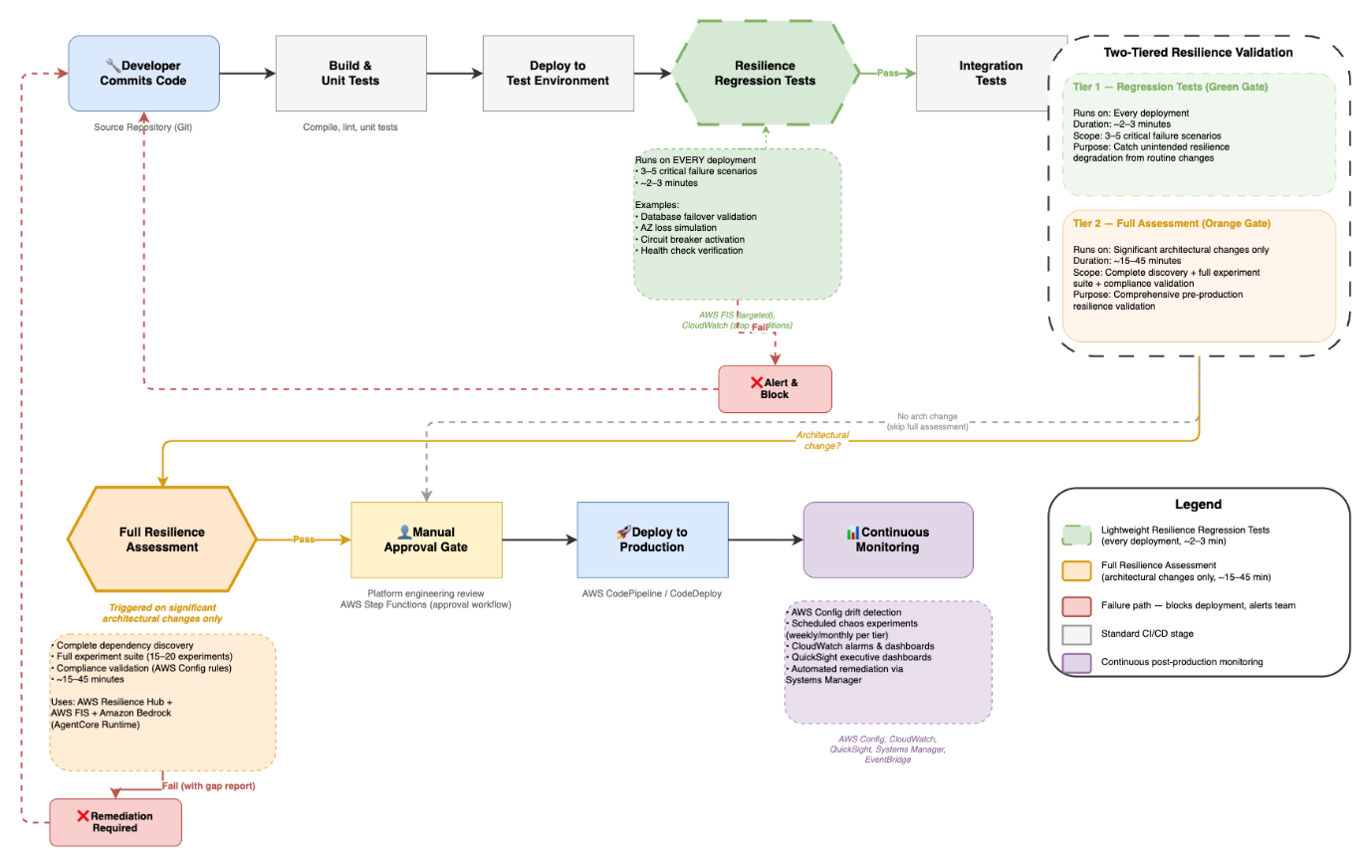
Full resilience assessments are better suited as a pre-production gate, triggered on significant architectural changes rather than every commit. For routine deployments, lightweight resilience regression tests (validating a focused set of critical failure scenarios like database failover, Availability Zone loss, and circuit breaker activation) run automatically to catch unintended resilience degradation from code or configuration changes. This two-tiered approach gives you comprehensive safety validation for major changes and continuous regression coverage for everyday deployments, without slowing your pipeline. Your new code and infrastructure changes trigger automated resilience assessments that identify potential weaknesses during development rather than after deployment, embedding this shift-left strategy directly into your CI/CD workflow.

The policy-as-code check adds seconds to each pipeline run. Full resilience assessments add approximately 2–3 minutes per experiment.

AWS Config drift detection identifies manual changes that bypass your deployment pipelines, helping keep your architecture aligned with tested configurations.

CI/CD pipeline with two-tiered resilience testing gates for routine deployments and architectural changes

Figure 3. Resilience testing in the CI/CD pipeline

Flowchart showing a CI/CD pipeline with two-tiered resilience testing. The top row shows the standard pipeline flow: Developer Commits Code → Build & Unit Tests → Deploy to Test Environment → Resilience Regression Tests (green hexagon gate, runs 3–5 critical scenarios in ~2–3 minutes on every deployment) → Integration Tests → Deploy to Staging. From staging, if an architectural change is detected, the flow drops to a second row: Full Resilience Assessment (orange hexagon gate, runs 15–20 experiments over ~15–45 minutes using AWS Resilience Hub, FIS, and Bedrock) → Manual Approval Gate → Deploy to Production → Continuous Monitoring. If no architectural change occurred, staging skips directly to the approval gate. Both resilience gates have failure paths (red) that block deployment and loop back to the developer. A legend and a side panel summarize the two tiers.

Continuous improvement through feedback

Experiment results feed back into the discovery and test generation layers, creating a continuous improvement cycle. When experiments reveal undocumented dependencies, the discovery layer updates your architecture map. When remediation actions successfully resolve failure patterns, Systems Manager automation documents capture these procedures for future use. The Bedrock agent analyzes experiment outcomes to refine hypothesis generation, deprioritizing consistently passing scenarios and focusing on emerging risk areas as your architecture evolves.

Key benefits

Now that you’ve seen how each layer works together, let’s examine the concrete benefits this architecture brings to your organization.

Faster infrastructure discovery: Manual infrastructure discovery requires significant effort across distributed teams, including cataloging resources, tracing dependencies, and validating configurations. Automated discovery reduces this from weeks to hours by programmatically querying cloud service APIs, analyzing infrastructure-as-code templates, and mapping dependencies. After implementation, the framework scales across your application portfolio without proportionally increasing staffing.

Removes expertise barrier: Without chaos engineering specialists, you can implement resilience testing using automated scenarios. Start with the AWS Fault Injection Service Scenarios Library for common failure patterns, then expand with scenarios specific to your architecture and customize based on your application’s specific failure modes.

Proactive risk identification: Automated discovery reveals critical single points of failure that manual audits consistently miss, including hard-coded endpoints, missing circuit breakers, and absent health checks. The system identifies vulnerabilities across your infrastructure and prioritizes them by business impact, so your teams can focus remediation on the highest-risk items first.

Faster recovery through automated remediation: Automated remediation reduces your mean time to resolution by removing manual intervention for common failure patterns in your environments. AWS Systems Manager automation documents codify recovery procedures discovered during chaos experiments. When Amazon CloudWatch alarms detect failure patterns in your systems, AWS Systems Manager automatically executes remediation actions, handling issues faster than manual response.

Continuous resilience validation: Integrating resilience assessments into your CI/CD pipelines catches regressions before production deployment, maintaining resilience as your system evolves rather than treating it as a one-time validation.

Framework components

AWS Resilience Hub serves as the central orchestration layer, defining your resilience policies, running assessments, and tracking improvements. Define RTO and RPO targets for each application tier based on your business impact analysis.

Amazon Bedrock delivers the AI capabilities that power discovery and test creation. AgentCore Runtime provides the managed hosting layer, handling session isolation, scaling, identity management, and observability, so your agent runs securely in production without infrastructure overhead.

Deploy a custom agent on Amazon Bedrock AgentCore, a framework-agnostic managed runtime that supports agents built with Strands, LangChain, or custom Python. The agent uses Amazon Bedrock to analyze your infrastructure context against architectural patterns, AWS documentation, and best practices. AgentCore Runtime’s built-in tool gateway provides controlled, secure access to your AWS APIs during discovery.

AWS Fault Injection Service runs controlled chaos experiments with built-in safety mechanisms on your infrastructure. Pre-built actions cover common failure scenarios: terminating Amazon EC2 instances, injecting network latency, throttling API calls, failing over Amazon RDS databases, and disrupting Availability Zone connectivity in your environments.

AWS Systems Manager extends your resilience framework beyond the default AWS Fault Injection Service actions. You can create custom automation documents that codify recovery procedures and transform manual runbooks into automated self-healing responses. When you build custom actions, you take on responsibility for proper rollback procedures and service state restoration. Design these with the same rigor you’d apply to your production runbooks.

AWS Config continuously monitors your resource configurations and tracks changes. AWS Config rules validate that your resources comply with resilience policies. For example, they verify your Amazon RDS instances use Multi-AZ deployment and confirm your Auto Scaling groups span multiple Availability Zones.

Prerequisites

To implement this framework, you’ll need:

  1. AWS account with administrative access.
  2. AWS Identity and Access Management (IAM) permissions for: AWS Resilience Hub, AWS Fault Injection Service, Amazon Bedrock AgentCore, AWS Systems Manager, and AWS Config. For each service, follow the principle of least privilege. Refer to the respective service documentation for minimum required permissions.
  3. The Amazon Bedrock AgentCore Starter Toolkitcreates broad dev/test permissions by default. Scope these down to least-privilege before production deployment.
  4. AWS Command Line Interface (AWS CLI) installed and configured.
  5. Basic understanding of AWS CloudFormation or Terraform.
  6. Non-critical application available for testing.
  7. Estimated time: 4–6 hours for pilot implementation (with a team of 2–3 engineers who have working knowledge of your AWS environment).
  8. Cost awareness: This implementation creates billable AWS resources including AWS Resilience Hub, AWS Fault Injection Service, Amazon Bedrock AgentCore, AWS Systems Manager, AWS Config, and Amazon CloudWatch. Follow the cleanup procedures after testing to avoid ongoing charges.

Getting started

A phased rollout builds confidence before expanding scope if you’re new to chaos engineering.

Pilot phase (1–2 weeks, 2–3 engineers)

  1. Select a non-critical application with well-understood architecture from your portfolio.
  2. Enable AWS Config across the regions where your application runs.
  3. Package your discovery agent code using Strands, LangChain, or custom Python.
  4. Deploy the packaged agent on Amazon Bedrock AgentCore using the Amazon Bedrock AgentCore Starter Toolkit. AgentCore Runtime handles the compute, session management, and security so you can focus on the agent logic and discovery scope. The runtime maintains stateful working context (including tool state and memory) across the multi-step infrastructure discovery workflow.
  5. Run a baseline resilience assessment in AWS Resilience Hub to identify initial architectural gaps. Resilience Hub evaluates your architecture against Well-Architected best practices and establishes your starting resilience posture. The Bedrock agent you deploy in the next step builds on this baseline, discovering undocumented dependencies and generating targeted experiments that go beyond standard recommendations.

Verify: Check the AWS Resilience Hub console for a completed assessment report showing baseline resilience scores and identified gaps. You should see a resilience score for each disruption type (AZ, Region, Application) and a list of recommended actions.

Expansion phase (4–6 weeks, cross-functional team)

  1. Expand to 3–5 applications across different tiers after validating safety with your pilot.
  2. Configure automated test creation to develop experiments specific to each of your application’s architectures.
  3. Run controlled chaos experiments starting with 1% scope during your low-traffic periods.

Verify: Review the AWS Fault Injection Service console for experiment status “Completed” and check Amazon CloudWatch metrics to confirm the 1% scope was applied without triggering stop conditions.

  1. Analyze results to identify common patterns across your applications.

Enterprise scale (8–12 weeks, dedicated resilience team)

  1. Expand resilience assessments in your CI/CD pipelines to comprehensive, multi-account validation.
  2. Configure centralized reporting across organizational units.
  3. Set up cross-account experiment coordination.
  4. Distribute shared experiment templates across organizational units using AWS Organizations.
  5. Deploy distributed worker pools for parallel testing across your multiple applications.
  6. Implement executive dashboards using Amazon QuickSight to track resilience trends across your portfolio.

When to move to enterprise patterns

Consider adopting the enterprise deployment patterns in the next section when you meet any of these criteria:

  • You manage dozens of applications across multiple AWS accounts.
  • Multiple business units require differentiated resilience policies based on varying risk tolerances, compliance requirements, or customer SLAs.
  • Compliance requirements demand centralized audit trails across accounts.
  • Your testing cadence exceeds what a single-account setup can handle.

Design considerations for enterprise deployment

When you’re ready to scale beyond initial pilots, consider these enterprise deployment patterns that handle the unique challenges of managing resilience testing across large organizations.

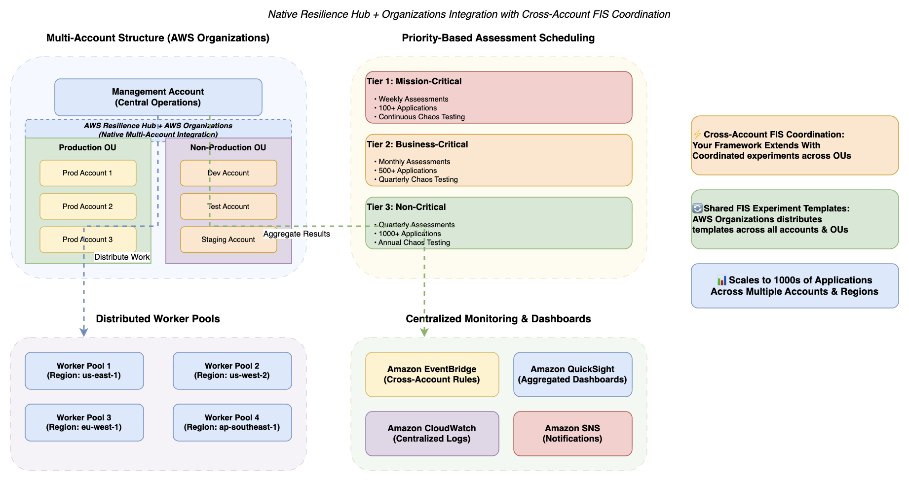
Enterprise scalability patterns showing multi-account structure with tiered resilience policies and distributed worker pools

Figure 4. Enterprise scalability patterns

Diagram showing multi-account structure with native AWS Resilience Hub and AWS Organizations integration. A central management account connects to Production and Non-Production organizational units with distributed application accounts. The framework extends this native integration with cross-account FIS coordination (coordinated experiments across OUs) and shared FIS experiment templates distributed via Organizations. Priority-based scheduling shows Tier 1 Mission-Critical (weekly assessments, 100+ applications), Tier 2 Business-Critical (monthly assessments, 500+ applications), and Tier 3 Non-Critical (quarterly assessments, 1000+ applications). Distributed worker pools operate across multiple AWS regions (us-east-1, us-west-2, eu-west-1, ap-southeast-1) with centralized monitoring via Amazon EventBridge, Amazon QuickSight dashboards, Amazon CloudWatch logs, and Amazon SNS notifications.

Multi-account architecture

The next generation of AWS Resilience Hub supports modular resilience policies that you can assign at the system, user journey, or service level. Choose this multi-account strategy if you manage more than 100 applications across different business units. When you have thousands of applications, assessing your workloads simultaneously from a single account becomes impractical. Implement a hub-and-spoke model (a centralized architecture pattern where a central “hub” account manages shared services while “spoke” accounts contain individual workloads) with centralized resilience testing infrastructure and distributed application ownership. Deploy AWS Resilience Hub and AWS Fault Injection Service in your central management account. Your production accounts contain application workloads and local AWS Config recorders. The next generation of AWS Resilience Hub natively integrates with AWS Organizations, enabling central teams to define resilience policies and monitor posture across all accounts and regions from a single dashboard. This framework extends native multi-account visibility with cross-account experiment coordination and shared experiment templates across organizational units. For guidance on structuring your multi-account environment, see Best practices for a multi-account environment and the Organizing Your AWS Environment Using Multiple Accounts whitepaper.

Tiered resilience policies

Not every workload justifies the same resilience investment. Implement tiered resilience based on your business impact analysis. For example, mission-critical applications might target stricter recovery objectives (such as RTO < 15 minutes, RPO < 5 minutes, 99.99% availability) with comprehensive quarterly chaos experiments, while business-critical applications might set moderate targets (such as RTO < 1 hour, RPO < 15 minutes, 99.9% availability) with monthly validation, and non-critical applications might accept longer recovery windows with quarterly assessments. This tiered strategy optimizes costs by focusing resilience investments on your highest-impact workloads.

Security and compliance

Under the AWS Shared Responsibility Model, AWS is responsible for security of the cloud (infrastructure), while you are responsible for security in the cloud (your configurations, data, and access management). The controls described below are your responsibility to configure and maintain. Encrypt your data at rest using AWS Key Management Service (AWS KMS) with customer-managed keys. Implement separate encryption keys per environment to limit the scope of unauthorized access in your infrastructure. Enforce Transport Layer Security 1.3 (TLS 1.3), a cryptographic protocol that secures data transmission, for data in transit. AWS CloudTrail delivers complete audit trails of your resilience operations. Automated compliance monitoring through AWS Security Hub (which continuously evaluates resources against standards including CIS AWS Foundations Benchmark, PCI DSS, and AWS Foundational Security Best Practices), combined with AWS Config conformance packs, streamlines evidence collection for Service Organization Control 2 Type II (SOC 2 Type II), International Organization for Standardization 27001 (ISO 27001), Payment Card Industry Data Security Standard (PCI DSS), and Digital Operational Resilience Act (DORA), an EU regulation requiring financial institutions to test operational resilience.

AI agent security: The Amazon Bedrock AgentCore-hosted agent operates with scoped IAM roles following least-privilege principles. AgentCore Runtime’s MicroVM session isolation makes sure that each discovery session runs in a dedicated, ephemeral environment with no cross-session data leakage. The agent’s infrastructure access is read-only during discovery and cannot modify resources. Amazon Bedrock interactions occur within your AWS account boundary, and no customer data is used for training purposes. For additional guardrails, you can configure Amazon Bedrock Guardrails to filter agent outputs and enforce responsible AI policies.

Note: This framework supports your compliance efforts but does not guarantee compliance with any regulatory framework. Compliance is a shared responsibility. Consult your legal and compliance teams and qualified auditors to validate that your implementation meets your specific regulatory obligations.

Addressing common concerns

Progressive scope expansion and automated stop conditions help you verify experiments reveal weaknesses without causing outages in your environments. Starting with 1% of your resources limits potential impact to statistically insignificant traffic. Organizations have validated this strategy using progressive scope expansion and automated stop conditions.

Automated scenarios remove the expertise barrier. The AI-powered analysis examines your specific architecture to develop targeted experiments rather than demanding you design tests manually. AWS CloudTrail provides comprehensive audit trails of your chaos experiments, which can help support due diligence documentation for resilience testing. This evidence can contribute to your compliance documentation for SOC 2, ISO 27001, and other frameworks relevant to your organization. For financial services, the framework supports DORA scenario testing requirements.

Clean up

To avoid ongoing charges, delete the resources you created during implementation:

  1. Delete your AWS Fault Injection Service experiment templates. Warning: This permanently removes experiment history and results. Consider exporting experiment data before deletion if you need to retain this information for compliance or analysis purposes.
  2. Remove your Amazon Bedrock AgentCore agent deployment, runtime endpoints, and associated configurations.
  3. Delete your AWS Systems Manager automation documents. Warning: This removes your automation runbooks permanently. Back up any custom runbooks you may want to reuse in future implementations.
  4. Remove your Amazon CloudWatch alarms created for stop conditions.
  5. Delete any AWS Step Functions state machines created for approval workflows.
  6. Remove any Open Policy Agent configurations deployed for IaC validation.
  7. Delete Amazon QuickSight dashboards created for resilience tracking (if applicable). Warning: This removes resilience trend data and operational insights. Export dashboard data or save analysis snapshots before deletion.
  8. Remove Amazon EventBridge rules and Amazon SNS topics created for notifications (if applicable).

Your AWS Resilience Hub and AWS Config continue incurring minimal costs. Consider retaining them for ongoing resilience validation.

Conclusion

In this post, I showed you how to build a five-layer AI-powered resilience framework that automatically discovers dependencies, generates targeted experiments, and integrates with your CI/CD pipelines. Building on the next generation of AWS Resilience Hub’s native dependency discovery and generative AI-powered failure mode analysis, this framework adds automated experiment generation through Amazon Bedrock AgentCore, controlled execution via AWS Fault Injection Service, and continuous CI/CD validation through AWS Systems Manager, creating an end-to-end resilience pipeline that goes from discovery to prevention.

The next frontier is shifting even earlier, scanning your Infrastructure as Code and application code for resilience anti-patterns before a single resource is deployed. When your CI/CD pipeline can flag a missing circuit breaker or a single-AZ dependency at the pull request stage, prevention becomes truly proactive.

The progressive strategy (starting with your single application pilot, expanding to multiple applications, then scaling organization-wide) builds confidence while demonstrating value at each phase. Organizations often realize positive return on investment through prevented events and reduced MTTR.

The framework makes resilience testing accessible to you, removing the expertise barrier that traditionally prevented adoption. Start with the pilot phase outlined earlier and expand to your mission-critical systems as confidence builds.

Ready to get started? Pick a non-critical application from your portfolio, deploy the discovery agent, and run your first assessment this week. Then share what you found. We’d love to hear about the hidden dependencies your team uncovered.

Have you implemented chaos engineering in your organization? What challenges did you face? Share your experience in the comments below.

Next steps

For the latest Resilience Hub capabilities including native dependency discovery and generative AI-powered failure mode analysis, see Introducing the next generation of AWS Resilience Hub and the next generation documentation.

Start with the resources most relevant to where you are in your resilience journey:

If you’re just getting started:

  1. For more information about resilience policies and assessment capabilities, see AWS Resilience Hub documentation.
  2. For hands-on experience with chaos engineering, see AWS Fault Injection Service Workshop.

If you’re ready to build:

  1. For information about creating fault injection experiments using natural language through Amazon Bedrock, see Chaos engineering made clear: Generate AWS FIS experiments using natural language through Amazon Bedrock.
  2. For information about assessing application resilience with AWS Resilience Hub and AWS CodePipeline, see Continually assessing application resilience with AWS Resilience Hub and AWS CodePipeline.
  3. For additional fault injection experiment templates, see AWS Fault Injection Service Template Library.

If you’re scaling to production: 6. For information about hosting production AI agents at scale, see Amazon Bedrock AgentCore 7. For sample agent code and deployment templates, see the Amazon Bedrock AgentCore Starter Toolkit.

Systems will face failures. Discover and fix weaknesses before your customers experience them by shifting your resilience testing from reactive response to proactive prevention.

If you have questions or need guidance implementing the framework, contact AWS or reach out to your AWS Solutions Architect.


About the author

Building highly available Oracle databases with Amazon FSx for NetApp ONTAP

Post Syndicated from Vignyanand Penumatcha original https://aws.amazon.com/blogs/architecture/building-highly-available-oracle-databases-with-amazon-fsx-for-netapp-ontap/

Oracle databases power mission-critical enterprise applications, making their continuous availability essential for business operations. Traditional Oracle high availability (HA) solutions require complex clustering software, expensive shared storage arrays, and specialized database administration teams. These conventional approaches often introduce single points of failure while demanding significant operational overhead.

Modern cloud architectures offer a transformative approach that combines Amazon FSx for NetApp ONTAP (FSxN) with Amazon EC2 Auto Scaling groups, automated AMI creation, AWS Lambda-driven orchestration, and AWS Systems Manager Parameter Store (SSM Parameter). This solution removes traditional Oracle HA complexities while delivering enterprise-grade availability, automated recovery, and makes sure new instances launch with the latest Oracle configuration.

This post shows how to build a highly available Oracle database architecture using FSxN shared storage, Auto Scaling groups with dynamic AMI updates, and serverless orchestration to help reduce recovery times with current configurations.

Solution overview

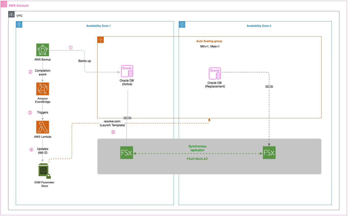
The solution uses multiple AWS services working together to create a comprehensive high availability architecture. FSxN Multi-AZ provides persistent shared storage spanning availability zones for Oracle database files, software, and configurations, so that data remains accessible when EC2 instances are replaced. Auto Scaling groups deliver automated instance lifecycle management with the latest AMI configurations, so failed instances are quickly replaced with identical configurations that can immediately access the existing Oracle database files on FSxN. AWS Backup creates AMIs that capture the latest Oracle host configurations including patches and settings, preserving the complete server state for consistent deployments. AWS Lambda extracts the AMI ID from backup recovery points and updates the SSM Parameter, orchestrating the entire configuration management workflow. Systems Manager Parameter Store stores the current AMI ID for Auto Scaling group launch templates, so new instances always launch with the most recent configuration and can immediately connect to the Oracle database on shared storage.

The following diagram shows the complete architecture with all AWS services and their interactions:

AWS architecture diagram showing Oracle Database disaster recovery across two Availability Zones using FSx for ONTAP synchronous replication, AWS Backup automation with EventBridge and Lambda, and Auto Scaling group with SSM Parameter Store for AMI management.

Key benefits include:

  • Recovery Time Objective (RTO): Can help achieve 2–5 minutes with latest Oracle configuration
  • Recovery Point Objective (RPO): Near-zero through synchronous Multi-AZ replication
  • Configuration consistency: New instances launch with identical Oracle host setup
  • Automated AMI management: Scheduled AMI creation with Parameter Store updates

Walkthrough

This walkthrough demonstrates implementing Oracle HA using Amazon FSx for NetApp ONTAP shared storage, AWS Backup-driven AMI creation, Lambda orchestration, and Auto Scaling groups with Parameter Store integration for configuration consistency and automated failover.

Prerequisites

For this walkthrough, you should have the following prerequisites:

  • An AWS account with appropriate permissions for Amazon FSx, Auto Scaling, EC2, Lambda, and Systems Manager
  • A VPC with subnets in at least two Availability Zones
  • Oracle database software

Keep in mind that customers are responsible for their own Oracle licensing compliance.

  • An EC2 instance with Oracle database installed and configured
  • AWS Identity and Access Management (IAM) roles for AMI creation and cross-service communication
  • Basic knowledge of Oracle database administration and AWS automation

Assumptions

This post is a conceptual illustration of the architecture. Your specific implementation will vary based on your VPC layout, Oracle version, storage requirements, and organizational security policies.

We assume the reader is familiar with:

  • Creating and configuring Amazon FSx for NetApp ONTAP file systems through the AWS console
  • iSCSI concepts including initiators, targets, and multipath I/O
  • Oracle database startup and shutdown procedures
  • AWS Backup, Lambda, and Auto Scaling group fundamentals

For detailed step-by-step instructions on specific AWS services, refer to the additional resources section.

Step 1: Create an Amazon FSx for NetApp ONTAP file system

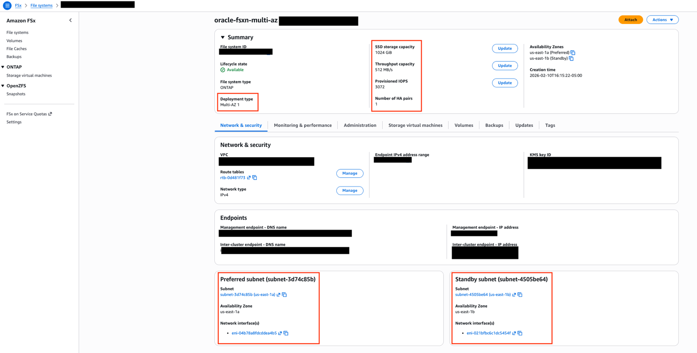
FSxN Multi-AZ provides the persistent shared storage foundation for this architecture. Unlike Amazon Elastic Block Store (Amazon EBS) volumes, which are bound to a single AZ, FSxN Multi-AZ replicates data synchronously across two AZs with automatic failover. This means that when an EC2 instance is replaced (whether in the same AZ or a different one), the new instance can immediately access the existing Oracle database files without restoring from backup.

To create the file system, navigate to the Amazon FSx console and select Amazon FSx for NetApp ONTAP as the file system type.

The critical configuration choice is selecting Multi-AZ deployment, which places an active file server in one AZ and a standby in another.

Amazon FSx console showing oracle-fsxn-multi-az file system configuration with ONTAP Multi-AZ 1 deployment, 1024 GiB SSD storage, 512 MB/s throughput, spanning us-east-1a preferred and us-east-1b standby subnets.

FSxN console showing Multi-AZ deployment type selection with preferred and standby subnets in separate availability zones.

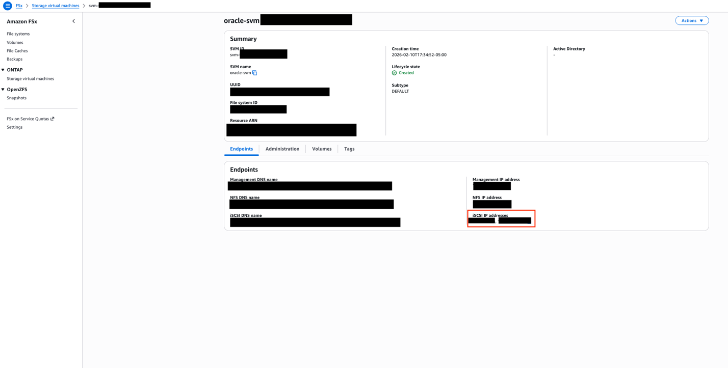
After the file system is created, you need to set up a Storage Virtual Machine (SVM), which acts as a logical storage container providing data access to your Oracle instances. The SVM creation is done from the FSx console under your file system’s details.With the SVM in place, the next step is configuring iSCSI access. FSxN exposes iSCSI endpoints—these are IP addresses (one per AZ) that your EC2 instances use to connect to the storage over the iSCSI protocol. You can find these endpoint addresses in the FSx console under your SVM’s Endpoints tab.

Amazon FSx Storage Virtual Machine configuration page showing oracle-svm with Created lifecycle state, NFS, iSCSI, and management endpoints for Oracle Database storage connectivity.

SVM Endpoints tab showing iSCSI endpoint IP addresses for each availability zone. These addresses are used in the EC2 instance’s iSCSI discovery configuration.

The iSCSI setup involves creating iGroups (which define which EC2 instances can access the storage) and LUNs (logical storage units mapped to those groups) through the NetApp ONTAP CLI. On the EC2 side, you configure the iSCSI initiator to discover and connect to the FSxN endpoints, then mount the resulting block devices. Using multipath I/O with both endpoints makes sure that Oracle data remains accessible even during an AZ failover. For detailed iSCSI configuration steps, see mounting iSCSI LUNs on Linux clients.

A dedicated security group is required for FSxN access. At minimum, the security group must allow inbound traffic on ports 111 (NFS portmapper), 635 (NFS mountd), 2049 (NFS), 3260 (iSCSI), 4045–4046 (NFS lock), 443 (HTTPS for management), and 22 (SSH for ONTAP CLI). Restrict the source to only your Oracle EC2 instances’ security group.

Step 2: Set up AWS Backup for EC2 instance protection

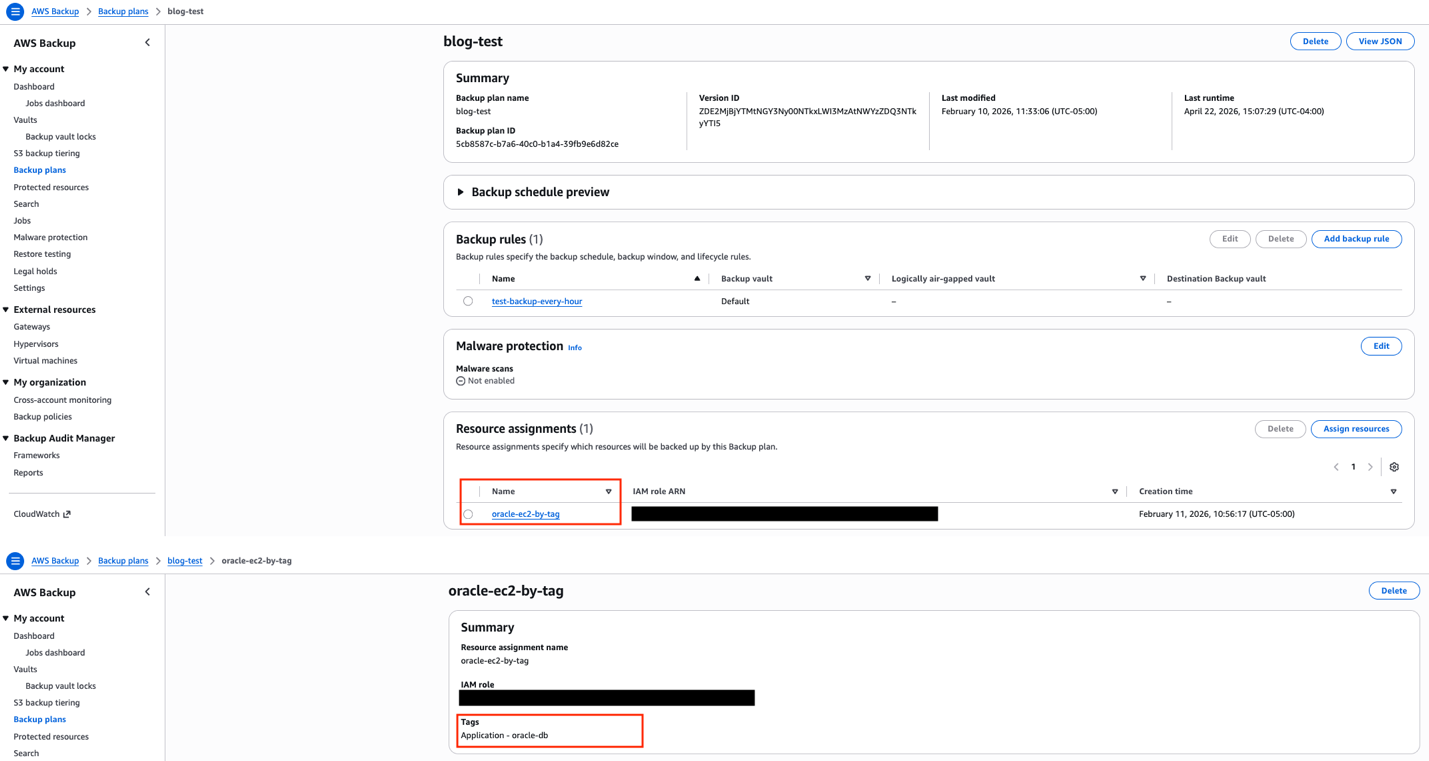
AWS Backup captures the complete state of your Oracle EC2 instance. The key design choice here is using tag-based resource selection rather than specifying instance IDs directly. Because Auto Scaling groups replace instances (and generate new instance IDs), tag-based selection makes sure that any new instance with the correct tags are automatically included in the backup plan.Configure a backup plan with a frequency appropriate for your environment and set the resource assignment to select EC2 instances matching your application tag (for example, ‘Application: Oracle’).

AWS Backup console showing blog-test backup plan with hourly backup rule targeting Oracle EC2 instances identified by the Application:oracle-db tag.

AWS Backup resource assignment configured with tag-based selection. Any EC2 instances tagged with the application tag are automatically included in the backup plan.

Step 3: Configure Lambda for AMI management

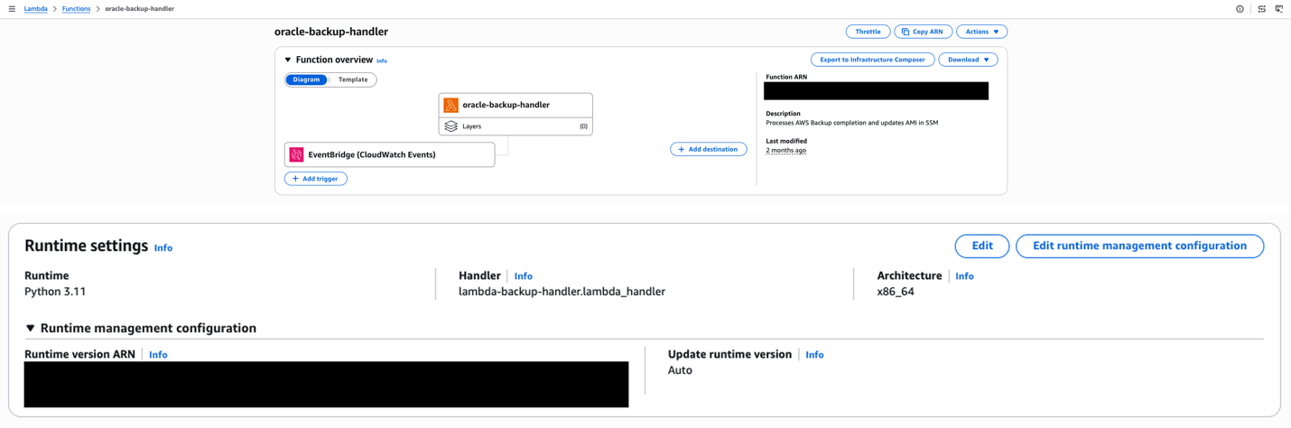
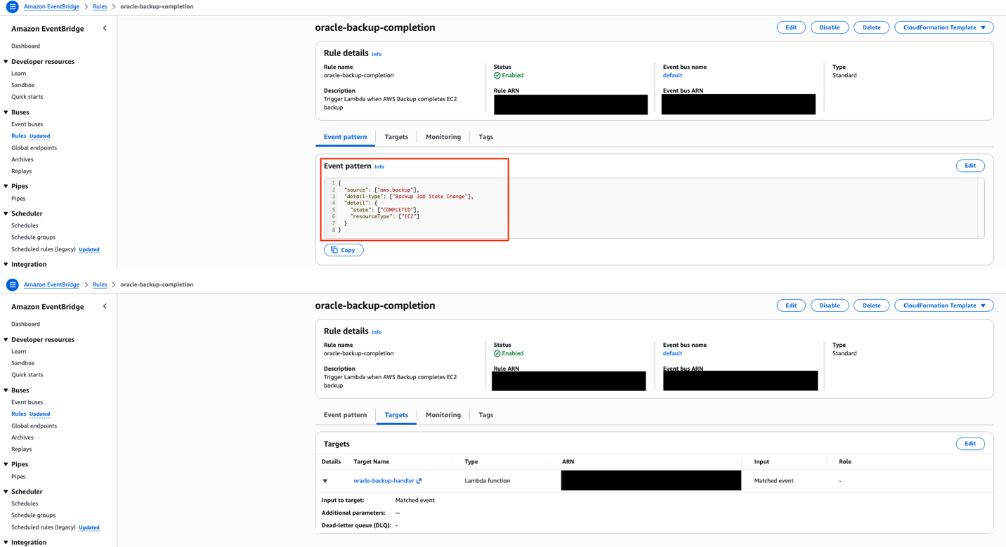
When AWS Backup completes an EC2 backup, it creates an AMI as the recovery point. An Amazon EventBridge rule detects this completion event and triggers a Lambda function. The function extracts the AMI ID from the backup recovery point, updates the SSM Parameter Store parameter with the new AMI ID, and cleans up older AMIs to control storage costs.

AWS Lambda function configuration for oracle-backup-handler showing Python 3.11 runtime, EventBridge trigger, and description indicating it processes AWS Backup completion events and updates AMI in SSM.

Lambda function overview showing the EventBridge trigger, Python 3.11 runtime, and function description indicating its role in processing backup completions and updating AMI references in SSM.

This event-driven approach means the latest AMI is available without manual intervention. The Lambda function needs IAM permissions for EC2 (to manage AMIs), SSM (to update the parameter), and Backup (to read recovery point metadata).

Amazon EventBridge rule oracle-backup-completion configured to trigger the oracle-backup-handler Lambda function when AWS Backup completes an EC2 backup job, with event pattern filtering for COMPLETED state.

EventBridge rule configured to match AWS Backup job completion events for EC2 resources, with the Lambda function as the target.

Step 4: Configure the Systems Manager Parameter Store

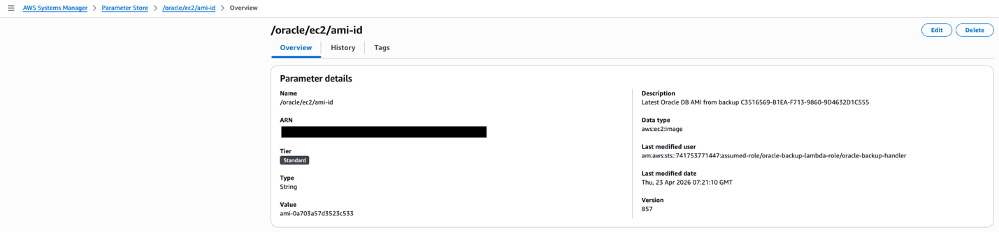
The SSM Parameter Store holds the current AMI ID that the Auto Scaling group’s launch template references. The parameter is created with the aws:ec2:image data type, which enables the launch template’s resolve:ssm: functionality, a feature that allows the launch template to dynamically resolve the AMI ID at instance launch time without requiring a template version update.

AWS Systems Manager Parameter Store showing /oracle/ec2/ami-id parameter with AMI value ami-0a705a7d5523c555, version 857, last modified by the oracle-backup-lambda-role on April 25, 2026.

SSM Parameter Store showing the /oracle/ec2/ami-id parameter with aws:ec2:image data type. The “Last modified user” confirms the Lambda function is automatically updating this parameter after each backup cycle.

When Lambda updates this parameter after each backup cycle, the next instance launched by the Auto Scaling group will automatically use the latest AMI. This removes the operational burden of manually updating launch template versions.

Step 5: Set up an Auto Scaling Group with dynamic AMI

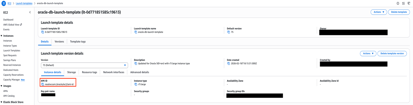
The launch template references the SSM parameter using the resolve:ssm: prefix for the AMI ID field. This is the mechanism that ties the entire automation pipeline together. The mechanism backups trigger AMI creation, AMI IDs flow into Parameter Store, and the launch template resolves the latest AMI at launch time.

EC2 Launch Template oracle-db-launch-template version 75 showing AMI ID resolved from SSM parameter resolve:ssm:/oracle/ec2/ami-id with r7i.large instance type for Oracle Database deployment.

Launch template AMI configuration showing the ‘resolve:ssm:’ prefix, which dynamically retrieves the latest AMI ID from Parameter Store at instance launch time.

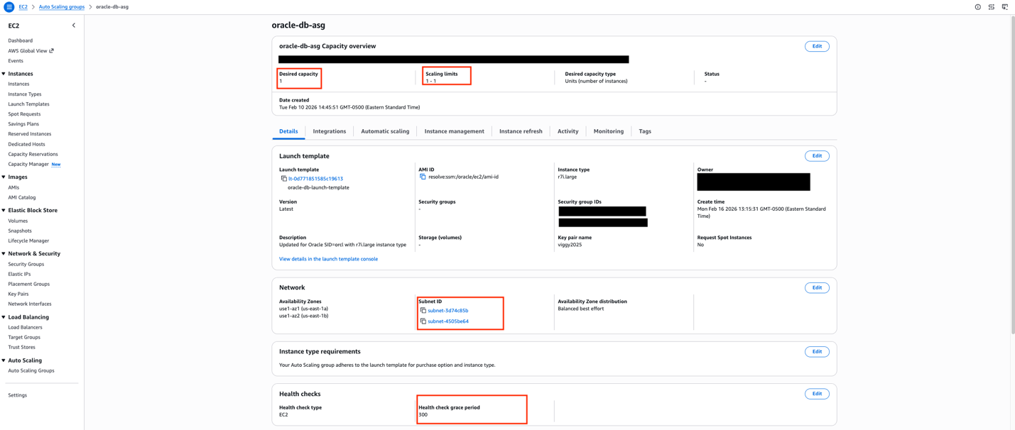
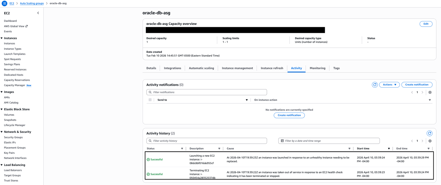
The Auto Scaling group is configured with minimum, maximum, and desired capacity all set to 1. This is not traditional auto-scaling, it’s a self-healing pattern. The sole purpose is to detect when the Oracle instance becomes unhealthy and automatically launch a replacement. The health check grace period should be set to at least 300 seconds (5 minutes) to allow Oracle sufficient time to start before health checks begin evaluating the new instance.

The launch template also includes a User Data script that runs on each new instance. This script configures the iSCSI initiator, discovers and connects to the FSxN endpoints, mounts the Oracle data volumes, and starts the Oracle database through a systemd service. This automation makes sure that a replacement instance is fully operational without manual intervention.

EC2 Auto Scaling group oracle-db-asg configuration showing desired capacity of 1, scaling limits 1-1, r7i.large instance type, oracle-db-launch-template with Latest version, spanning two availability zone subnets.

Auto Scaling group configured with min=max=desired=1 across two availability zones, providing self-healing capability.

Test the complete workflow

To validate the architecture, simulate an instance failure by terminating the current Oracle EC2 instance.

The expected sequence is:

  1. The Auto Scaling group detects the instance is unhealthy (within approximately 30 seconds)
  2. A new instance launches from the latest AMI resolved from Parameter Store (approximately 2 minutes)
  3. The User Data script connects to FSxN using iSCSI and starts Oracle (approximately 2–3 minutes)
  4. The Oracle database is available and accepting connections (total elapsed: approximately 5 minutes)

Auto Scaling group Activity History showing the self-healing sequence — the unhealthy instance is terminated, and a replacement is launched automatically within seconds.

The new instance automatically inherits the application tags from the Auto Scaling group, which means AWS Backup includes it in the next backup cycle without manual configuration.

Cleaning up

To avoid incurring future charges, delete the resources:

  • Delete Lambda functions and EventBridge rules
  • Remove Parameters from Systems Manager Parameter Store
  • Delete AWS Backup plans and backup vault
  • Deregister created AMIs
  • Terminate Auto Scaling group instances
  • Delete the Amazon FSx for NetApp ONTAP file system

Conclusion

This architecture facilitates Oracle high availability with configuration consistency by combining FSxN persistent shared storage with automated AMI management and AWS Backup protection. The Lambda-driven AMI management from backup recovery points and Parameter Store integration helps make sure that replacement instances launched by Auto Scaling groups always use the latest Oracle host configuration and can immediately connect to the existing Oracle database files stored on FSxN. Replacements occur only when health checks fail. Organizations can target high availability while maintaining configuration consistency across instance replacements. The automated AMI management alleviates configuration drift and makes sure that disaster recovery scenarios restore Oracle instances with identical host-level configurations that can immediately access the persistent Oracle database on shared storage. Healthy instances continue running unchanged, with replacements occurring only, when necessary, because of health check failures.Next steps include implementing cross-Region AMI replication, adding AMI validation testing, and developing custom health checks that verify both Oracle database and host configuration consistency.

Additional resources

Automating identity lifecycle and security with AWS Directory Service APIs

Post Syndicated from Ali Alzand original https://aws.amazon.com/blogs/security/automating-identity-lifecycle-and-security-with-aws-directory-service-apis/

Managing identities and access across complex environments has become more critical than ever. AWS Directory Service for Managed Microsoft Active Directory, also known as AWS Managed Microsoft AD, has added new capabilities to manage users and groups. Now, you can perform create, read, update, and delete (CRUD) operations on users and groups directly through AWS Command Line Interface (AWS CLI), APIs, and the AWS Management Console. You can use this powerful capability to automate identity lifecycle management and enhance security in your AWS environment. By using these APIs, collectively known as the Directory Service Data APIs, you can perform operations such as:

  • Listing users and groups
  • Retrieving user and group details
  • Disabling and enabling user accounts
  • Resetting user passwords
  • Managing group memberships

These APIs provide new possibilities for automating identity management tasks and integrating Active Directory management into your existing workflows and applications.

The introduction of these APIs brings several key benefits:

  • Automation of the identity lifecycle: You can now programmatically manage user accounts throughout their lifecycle—from creation to deletion—enabling streamlined onboarding and offboarding processes.
  • Enhanced security: By integrating these APIs with security services like Amazon GuardDuty, you can create automated responses to potential security threats, such as disabling accounts with inappropriate access.
  • Improved compliance: You can use automated user management to help enforce consistent policies and help maintain compliance with various regulatory requirements.
  • Operational efficiency: You can automate routine tasks such as user provisioning, deprovisioning, and group management, reducing manual effort and the potential for human error.
  • Integration capabilities: By using these APIs, you can seamlessly integrate with existing identity management systems, custom applications, and third-party tools.
  • Cost optimization: By automating processes and reducing manual intervention, you can potentially help your organization optimize operational costs associated with identity management.

In this post, we explore these new APIs and demonstrate how you can use them to create an automated solution for detecting and responding to unexpected behavior by Active Directory users. We walk through a practical example that combines GuardDuty, AWS Step Functions, Amazon EventBridge, and the new AWS Directory Service APIs to create a robust security automation workflow.

Solution overview

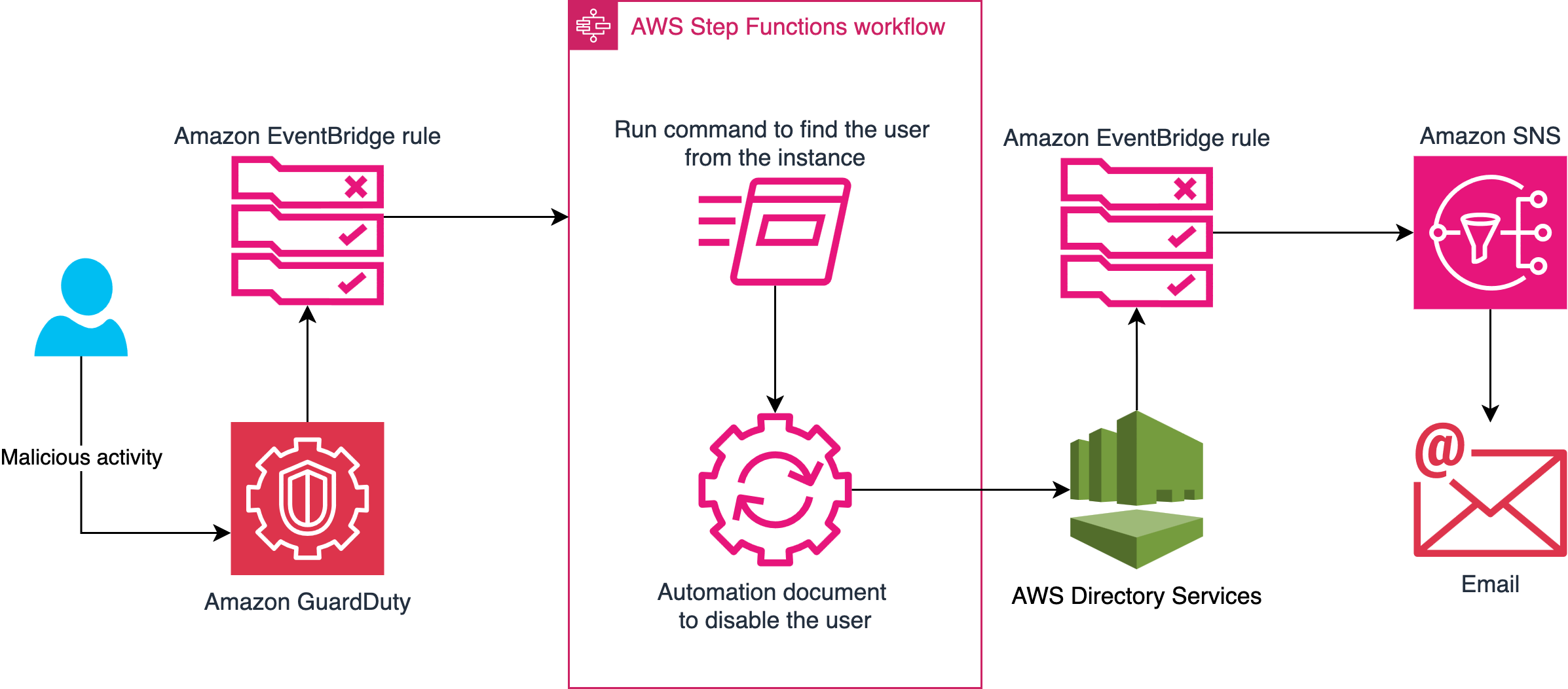
To demonstrate the power of these new APIs, let’s explore a practical solution that automates the detection and response to unexpected behavior by Active Directory users. This solution combines several AWS services to create a robust security automation workflow:

    1. GuardDuty continuously monitors for unexplained behavior of Active Directory users from AWS Managed Microsoft AD. For the example in this post, we’re using Backdoor:Runtime/C&CActivity.B!DNS
    2. An EventBridge rule detects GuardDuty findings related to these users and triggers a Step Functions workflow.
      {
        "detail-type": ["GuardDuty Finding"],
        "source": ["aws.guardduty"],
        "detail": {
          "type": ["Backdoor:Runtime/C&CActivity.B!DNS"]
        }
      }

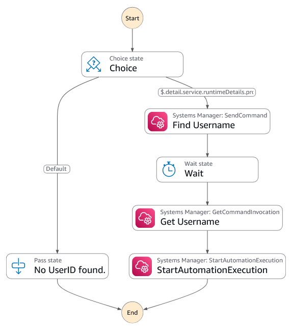
    3. The Step Functions workflow will:
      1. Extract the Active Directory username from the instance using a run command.
      2. Start an automation that will disable the account using the DisableUser API.
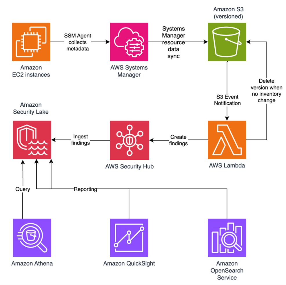
Figure 1: Diagram of the Step Functions workflow showing the process of Systems Manager finding the username and starting the automation to disable the account

Figure 1: Diagram of the Step Functions workflow showing the process of Systems Manager finding the username and starting the automation to disable the account

  1. Finally, another EventBridge rule will monitor the DisableUser API call. It will send an email to the user using Amazon Simple Notification Service (Amazon SNS) notifications.
    {
      "detail-type": ["AWS API Call via CloudTrail"],
      "source": ["aws.ds"],
      "detail": {
        "eventSource": ["ds.amazonaws.com"],
        "eventName": ["DisableUser"]
      }
    }

This solution delivers automated, near real-time remediation of potential security threats — significantly reducing exposure windows and containing the impact of unauthorized account access.

The following figure shows a high-level architecture diagram of the solution.

Figure 2: Diagram showing the workflow of what happens when potentially damaging activity is detected

Figure 2: Diagram showing the workflow of what happens when potentially damaging activity is detected

Note: The solution must be deployed in the primary AWS Region of your directory.

Prerequisites

To complete the walkthrough in this post, you must have the following prerequisites in place.

GuardDuty

GuardDuty is an automated threat detection service that continuously monitors for unexpected activity and unauthorized behavior to protect your AWS accounts, workloads, and data stored in Amazon Simple Storage Service (Amazon S3).

To activate GuardDuty:

  1. Go to the GuardDuty console.
    1. If you’re activating GuardDuty for the first time, under Try threat detection with GuardDuty, select All Features and then choose Get Started.
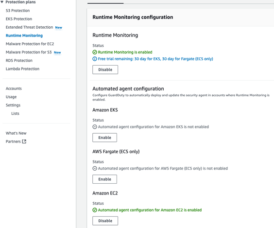
    2. If you’ve used GuardDuty before, select Runtime Monitoring and then choose Enable under Runtime Monitoring.
Figure 3: Runtime Monitoring enabled

Figure 3: Runtime Monitoring enabled

AWS Managed Microsoft AD

AWS Managed Microsoft AD provides a fully managed service for Microsoft Active Directory (AD) in the AWS Cloud. When you create your directory, AWS deploys two domain controllers that are exclusively yours in separate Availability Zones for high availability. For use cases that require even higher resilience and performance in a specific AWS Region or during specific hours, you can scale AWS Managed Microsoft AD by deploying additional domain controllers to meet your needs. These domain controllers can help load balance, increase overall performance, or provide additional nodes to protect against temporary availability issues. Using AWS Managed Microsoft AD, you can define the correct number of domain controllers for your directory based on your use case.

To deploy a new AWS Managed Microsoft AD:

  1. Go to the Directory Service console.
  2. Choose Set up directory and select AWS Managed Microsoft AD.
  3. Select Standard Edition and enter a directory DNS name and password.
  4. Select a virtual private cloud (VPC). For this example, use the Default VPC.
  5. Choose Create directory.

Create a test Active Directory user

You will use this test user account to sign in to an EC2 instance and initiate a command that simulates unexplained activity that results in this account being disabled.

To create the test user, you can use AWS CloudShell or the AWS CLI from your local machine. Run the following commands, replacing the --directory-id value with your own:

# Create the test user
aws ds-data create-user \
 --directory-id "your-directory-id" \
 --sam-account-name "TestUser" \
 --given-name "Test" \
 --surname "User"

Then

# Set a password for the test user 
aws ds reset-user-password \
 --directory-id "your-directory-id" \
 --user-name "TestUser" \
 --new-password "YourSecurePassword123!"

In this example, the password is set to YourSecurePassword123!. If you need to replace it with a password that meets your organization’s requirements, see Resetting and enabling an AWS Managed Microsoft AD user’s password. For more information on creating users, see Creating an AWS Managed Microsoft AD user in the AWS Directory Service documentation.

Test EC2 instance

To generate alerts on GuardDuty, you need a domain joined Linux EC2 instance. If you don’t have a domain joined EC2 Linux instance, follow these instructions for joining a Linux instance to an Active Directory domain. This instance will be used to simulate suspicious activity that triggers a GuardDuty finding and initiates the automated remediation workflow.

Implement the solution

Let’s walk through the steps to implement this solution in your AWS environment.

Deploy the solution

  1. Download the CloudFormation template
  2. Navigate to the CloudFormation console in the AWS account.
  3. For Create Stack, choose with new resources (standard).
  4. For Template source, choose Upload a template file. Choose Choose file and select the template you downloaded in step 1.
  5. Choose Next.
  6. For Stack name, enter a stack name (such as CRUD-API-MAD).
  7. In the Parameters area, do the following:
    1. For DirectoryID, enter the AWS Active Directory ID.
    2. For NotificationEmail, enter the email address to send the notification to.
  8. On the Configure stack options page, choose Next.
  9. Select I acknowledge that AWS CloudFormation might create IAM resources with custom names, then choose Submit.

After the page is refreshed, the status of your stack should be CREATE_IN_PROGRESS. When the status changes to CREATE_COMPLETE, proceed to the next section.

Test

To simulate a threat, use a GuardDuty test domain that GuardDuty will recognize as a command and control server.

  1. Go to the Amazon EC2 console.
  2. Choose Instances from the navigation pane.
  3. Select the test EC2 instance that you created earlier.
  4. Choose Connect, select the Session Manager tab, and choose Connect.
  5. Authenticate with your test user by entering su followed by the test user with the domain name that you created earlier. For example su [email protected], then enter the password.
  6. Enter the command curl guarddutyc2activityb.com.
    You will receive an error because the page won’t resolve, but GuardDuty will have detected concerning events.
  7. Go to the GuardDuty console and select Findings from the navigation pane.
  8. Within 3–5 minutes, you should see a high severity finding for Backdoor:Runtime/C&CActivity.B!DNS.
  9. This will then trigger the automation to disable the account.
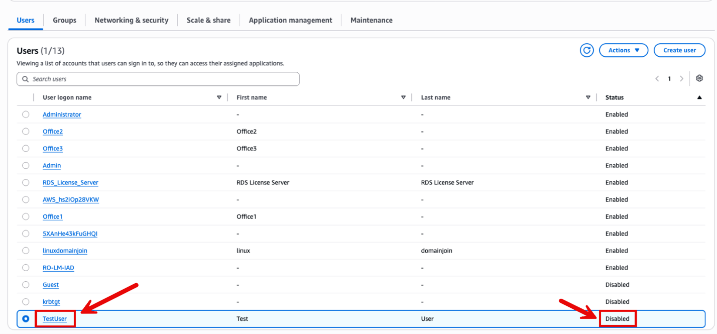
    Figure 4: Account successfully disabled

    Figure 4: Account successfully disabled

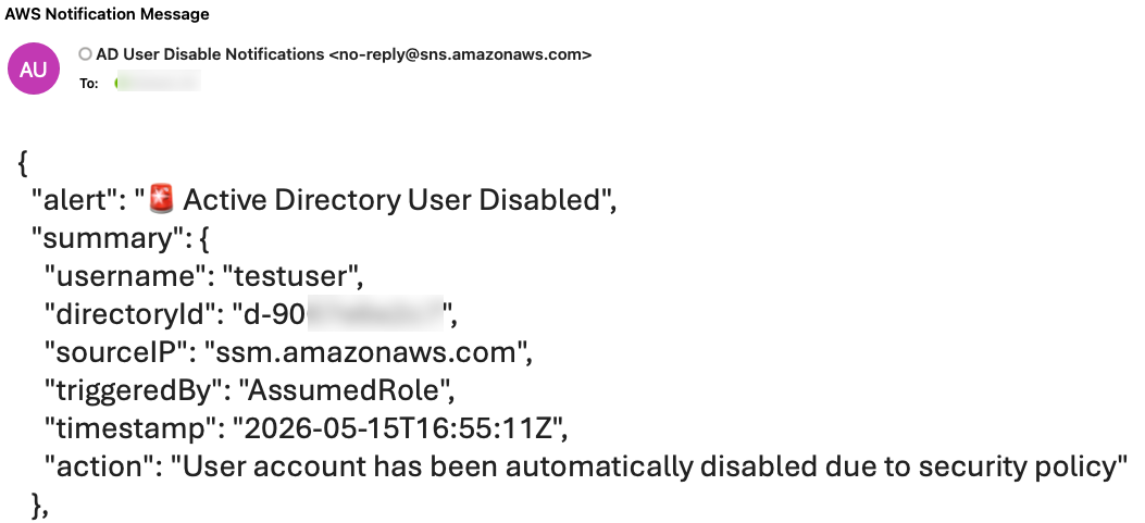
  10. After the account is disabled, an email notification will be sent notifying an administrator that the account was disabled (it might take up to 5 minutes to receive the notification).

    Figure 5: AWS notification message showing the username has been disabled

    Figure 5: AWS notification message showing the username has been disabled

Note: You must archive the GuardDuty finding before running this test again, because the EventBridge rule only runs once against a GuardDuty finding with the same details. To archive the finding, select the check box next to the Backdoor:Runtime/C&CActivity.B!DNS finding, choose Actions (top right), and select Archive.

Conclusion

The new AWS Directory Service APIs for AWS Managed Microsoft AD provide powerful capabilities for programmatically managing Active Directory users and groups. By using these APIs in conjunction with services such as Amazon GuardDuty and AWS Step Functions, you can create sophisticated automation workflows that enhance your security posture and streamline identity management processes.

The solution we’ve explored in this post demonstrates just one of many possible use cases for these new APIs. As you integrate these capabilities into your own environments, you will probably discover numerous opportunities to improve efficiency, security, and compliance in your identity management practices.

For a solution that uses PowerShell Active Directory cmdlets with AWS Systems Manager Run Command to disable users, see How to automatically disable users in AWS Managed Microsoft AD based on GuardDuty findings.

For more information about AWS Directory Service and its APIs, visit the AWS Directory Service documentation.

We’re excited to see how you’ll use these new APIs to innovate and improve your identity management workflows. If you have any questions or want to share your own use cases, leave a comment below or reach out to AWS Support.

Remember, the cloud journey is all about continuous improvement and innovation. Keep exploring, keep learning, and keep pushing the boundaries of what’s possible with AWS.

Ali Alzand

Ali Alzand

Ali is a Senior Infrastructure Migration & Modernization Specialist Solutions Architect at AWS who helps enterprise customers migrate, modernize, and operate their Microsoft workloads on AWS. He specializes in Infrastructure as Code, automating at scale with AWS Systems Manager, EC2 Image Builder, and CloudFormation. He also designs event-driven architectures building responsive, loosely coupled solutions with EventBridge and Lambda. Outside of work, Ali enjoys grilling with friends and discovering new cuisines around town.

Kevin Sookhan

Kevin Sookhan

Kevin is a Specialist Solutions Architect at Amazon Web Services with over 20 years of experience working with Microsoft technologies. He has expertise in running Microsoft workloads on AWS with specialization in helping customers with their migrations, cost optimization, and infrastructure architecture.

Build a multi-tenant configuration system with tagged storage patterns

Post Syndicated from Koshal Agrawal original https://aws.amazon.com/blogs/architecture/build-a-multi-tenant-configuration-system-with-tagged-storage-patterns/

In modern microservices architectures, configuration management remains one of the most challenging operational concerns. Two gaps emerge as organizations scale: handling tenant metadata that changes faster than cache TTL allows, and scaling the metadata service itself without creating a performance bottleneck.

Traditional caching strategies force an uncomfortable trade-off: either accept stale tenant context (risking incorrect data isolation or feature flags), or implement aggressive cache invalidation that sacrifices performance and increases load on your metadata service. When tenant counts grow into the hundreds or thousands, this metadata service itself becomes a scaling challenge, particularly when different configuration types have vastly different access patterns.

The challenge intensifies when you need to support different storage backends for different configuration types. Some require high-frequency access patterns suited for Amazon DynamoDB, while others benefit from the hierarchical organization and built-in versioning of AWS Systems Manager Parameter Store. Traditional solutions often force engineering teams into a corner: either build multiple configuration services (increasing operational overhead), or compromise on performance by using a single storage backend that isn’t optimized for every use case.

In this post, we demonstrate how you can build a scalable, multi-tenant configuration service using the tagged storage pattern, an architectural approach that uses key prefixes (like tenant_config_ or param_config_) to automatically route configuration requests to the most appropriate AWS storage service. This pattern maintains strict tenant isolation and supports real-time, zero-downtime configuration updates through event-driven architecture, alleviating the cache staleness problem.

What you’ll learn:

  • Implementing a multi-tenant data model with DynamoDB and Parameter Store
  • Using the Strategy pattern for flexible storage backend switching
  • Building tenant isolation through JSON Web Token (JWT) claims
  • Creating an event-driven auto-refresh mechanism with Amazon EventBridge and AWS Lambda
  • Implementing zero-downtime configuration updates with gRPC (a high-performance communication protocol) streaming
  • Addressing the cache TTL problem for rapidly-changing tenant metadata

By the end of this post, you’ll understand how to architect a configuration service that handles complex multi-tenant requirements while optimizing for both performance and operational simplicity.

Solution overview

The architecture uses four AWS services orchestrated through a NestJS-based gRPC service to create a reliable, event-driven configuration management system. Let’s first understand the overall architecture before diving into each component’s implementation details.

Architecture components

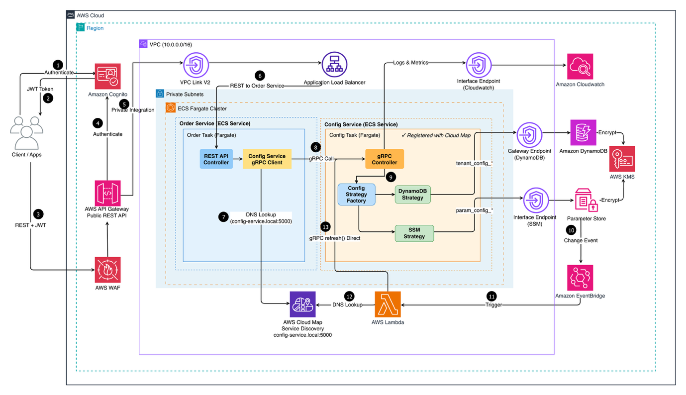
The following diagram shows the end-to-end architecture of the Multi-Tenant Configuration Service deployed on AWS, from how client requests enter the system to how configuration data is retrieved from the right storage backend.

WS microservices architecture diagram showing ECS Fargate services, API Gateway, Cognito auth, DynamoDB, and CloudWatch monitoring

Figure 1: Multi-Tenant Configuration Service Architecture

Client applications authenticate via Amazon Cognito and pass through AWS WAF before reaching Amazon API Gateway. Traffic is then routed through a VPC Link to an Application Load Balancer, which distributes requests across two core microservices running on Amazon Elastic Container Service (Amazon ECS) on AWS Fargate within private subnets :

  • Order Service— handles incoming REST requests and delegates configuration lookups to the Config Service via gRPC
  • Config Service— exposes a gRPC API and uses a Config Strategy Factory to dynamically select the appropriate storage backend (DynamoDB or Parameter Store) based on the request

Service discovery is managed by AWS Cloud Map, while Amazon CloudWatch centralizes logs and metrics across services.

The system is organized into four interconnected layers, each addressing a specific aspect of the configuration management challenge:

1. Storage layer – multi-backend strategy

The storage layer strategically uses two complementary AWS services, each optimized for different configuration access patterns and requirements.

  • Amazon DynamoDB: Stores tenant-specific configurations. These are settings unique to each customer, such as payment gateway preferences or feature flags. With single-digit millisecond latency, DynamoDB handles high-frequency reads efficiently. The schema uses composite keys (TENANT#{tenantId} as partition key, CONFIG#{configType} as sort key) for efficient tenant-scoped queries and built-in multi-tenant isolation at the data model level.
  • AWS Systems Manager Parameter Store: manages shared parameters. These are configuration values used across multiple services or tenants, such as API endpoints, database connection strings, and region-specific settings. Unlike tenant-specific configs that change frequently, these parameters are relatively static but benefit from hierarchical organization. The path structure (/config-service/{tenantId}/{service}/{parameter}) enables bulk retrieval operations, reducing the number of API calls needed during service initialization from dozens to a single request.

2. Service layer – gRPC with strategy pattern

A NestJS-based microservice implements the configuration retrieval logic using gRPC for high-performance, type-safe communication. This choice significantly reduces network bandwidth and improves response times for service-to-service communication where compatibility with web browsers isn’t a requirement.

At the core is a Strategy Pattern implementation that determines the optimal storage backend based on configuration key prefixes. This pattern simplifies the addition of new storage backends (like Amazon Simple Storage Service (Amazon S3) for large configuration files) without modifying the core service logic.

3. Authentication layer – Amazon Cognito

User authentication flows through Amazon Cognito with custom attributes:

  • custom:tenantId (immutable) – Tenant identifier embedded in JWT
  • custom:role (mutable) – User role for authorization

Critical security design: The service never accepts tenantId from request parameters. Instead, it extracts the tenant context from validated JWT tokens, making sure requests cannot access other tenants’ data even if they attempt to manipulate request payloads.

4. Event-driven refresh layer

Traditional configuration updates present a dilemma: how do you keep services synchronized without compromising performance or causing downtime?

Polling approaches continuously check for changes, generating unnecessary API calls that cost money even when nothing changes. They also introduce delays. Services don’t see updates until the next poll cycle, which could be seconds or minutes later.

Service restart approaches cause downtime, drop active connections, and disrupt user sessions. For SaaS applications serving customers 24/7, restart-based updates are unacceptable.

The event-driven refresh layer addresses both problems by implementing a reactive architecture where Amazon EventBridge monitors Parameter Store for changes and triggers AWS Lambda to update the service’s local cache. This achieves configuration updates within seconds while users experience no interruption.

Technical implementation

The following sections detail the implementation, starting with the data model, which serves as the backbone for tenant isolation and efficient querying.

A. Multi-tenant data model

The foundation of tenant isolation begins with the data model. Using DynamoDB’s composite key structure, we achieve both tenant isolation and efficient querying without requiring separate tables per tenant.

DynamoDB schema design:

The following example shows a tenant-specific configuration stored in DynamoDB, illustrating how composite keys enable both isolation and efficient access:

{
  "pk": "TENANT#acme-corp",
  "sk": "CONFIG#payment-gateway",
  "config": {
    "providers": [
      {
        "name": "Stripe",
        "apiEndpoint": "https://api.stripe.com",
        "retryPolicy": "exponential"
      }
    ]
  },
  "isActive": true,
  "version": 2,
  "createdAt": "2024-01-15T10:30:00Z",
  "updatedAt": "2024-02-20T14:45:00Z"
}

Key schema decisions:

  1. Partition key pattern: TENANT#{tenantId} makes sure tenant data is co-located, enabling efficient tenant-scoped queries while maintaining logical separation.
  2. Sort key pattern: CONFIG#{configType} allows querying specific configuration types within a tenant’s data. The CONFIG# prefix enables future expansion with other entity types (for example, METADATA#, AUDIT#).
  3. Soft deletion: The isActive boolean flag supports soft deletion, maintaining audit trails while excluding inactive configurations from queries.
  4. Versioning: The version field tracks configuration changes, supporting rollback capabilities and change history.

Parameter store organization:

Parameters follow a hierarchical structure that mirrors the multi-tenant model. This example demonstrates the path structure:

/config-service/
├── acme-corp/
│   ├── api/
│   │   ├── api-key
│   │   └── endpoint
│   └── database/
│       └── connection-string
└── globex-inc/
    ├── api/
    │   ├── api-key
    │   └── endpoint
    └── database/
        └── connection-string

This structure provides several benefits:

  • Bulk retrieval using path prefix (GetParametersByPath API)
  • Clear ownership and access control through AWS Identity and Access Management (AWS IAM) policies
  • Environment separation (dev/staging/prod) at the path level
  • Automatic parameter versioning and change tracking

Advanced: Multi-dimensional tenant context
For organizations with multiple services requiring different configuration scopes, consider introducing a second dimension in the partition key:

PK = "TENANT#acme-corp|SERVICE#order-service"
SK = "CONFIG#payment-gateway"

This multi-dimensional approach enables service-level isolation where the Order service sees only billing API configurations while the Reporting service doesn’t have access to payment gateway settings. It also provides efficient service-scoped queries, retrieve configurations for a specific service with PK = TENANT#acme-corp|SERVICE#order-service and SK begins with CONFIG#. The second dimension can represent business units, geographic regions, or a logical boundary that aligns with access control requirements, making this pattern particularly valuable when fine-grained access control beyond tenant-level isolation is needed. For detailed guidance on multi-tenant DynamoDB modelling patterns, see amazon-dynamodb-data-modeling-for-multi-tenancy-part-2.

B. Strategy pattern for storage flexibility

The system decides which storage backend to use for each configuration request. The Strategy Pattern is a design approach that allows a program to choose different behaviors at runtime based on context. Think of it like a traffic controller that examines each request and directs it to the appropriate service.

Why use the strategy pattern?

Without the Strategy Pattern, handling multiple storage backends would require complex conditional logic throughout the code base. Different tenant metadata has vastly different access patterns. Routing to optimized backends alleviates both DynamoDB cost explosions (for rarely-changing configs) and Parameter Store throttling (for high-frequency reads), addressing the scaling gap. A naive implementation might look something like this and it’s worth pausing to understand why this approach breaks down.

// Without Strategy Pattern - complex and hard to maintain
async getConfig(key: string, tenantId: string) {
  if (key.startsWith('tenant_config_')) {
    // DynamoDB logic here
    const pk = `TENANT#${tenantId}`;
    const sk = `CONFIG#${key.slice(14)}`;
    return await this.dynamoDB.query({...});
  } else if (key.startsWith('param_config_')) {
    // Parameter Store logic here
    const path = `/config-service/${tenantId}/${key.slice(13)}`;
    return await this.ssm.getParameter({...});
  }
  // More conditions as backends are added...
}

Every time you add a new storage backend, say, AWS Secrets Manager or Amazon S3, you’re forced to reach back into this function and bolt on another else if. The storage logic becomes tightly coupled to your service layer, making it harder to test each backend in isolation and nearly impossible to swap one out without risking regressions elsewhere.

Implementation strategy

The Strategy Pattern encapsulates storage-specific logic into separate, interchangeable strategy classes. This code demonstrates how the factory examines keys and selects strategies:

@Injectable()
export class ConfigStrategyFactory {
  private keyStrategyMap = new Map<string, ConfigStrategy>([
    ['tenant_config_', this.dynamoDBConfigStrategy],
    ['param_config_', this.ssmConfigStrategy],
  ]);
  getStrategy(key: string): ConfigStrategy {
    for (const [prefix, strategy] of this.keyStrategyMap.entries()) {
      if (key.startsWith(prefix)) {
        return strategy;
      }
    }
    throw new ValidationException(`Invalid key format: ${key}`);
  }
}

Key prefix mapping:

  • tenant_config_* → Routes to Amazon DynamoDB for tenant-specific, high-frequency access patterns
  • param_config_* → Routes to AWS Systems Manager Parameter Store for shared, hierarchical parameters

With this approach, adding a new storage backend requires only:

  • Creating a new strategy class implementing the ConfigStrategy interface
  • Adding one line to the keyStrategyMap with the new prefix and strategy
  • No changes to existing strategies or calling code

This design helps protect technology investments. As requirements evolve and new AWS services become relevant, the system adapts without major rewrites.

Multi-layer caching strategy

Different configurations benefit from different caching approaches. The pattern implements different caching strategies optimized for each configuration type’s access patterns and business requirements:

  • High-frequency tenant configurations (accessed thousands of times per minute) use application-level caching with short Time-To-Live (TTL) values. This significantly reduces database queries while maintaining reasonably fresh data.
  • Shared parameters (accessed frequently but change rarely) use in-memory caching with event-driven invalidation. The cache only refreshes when EventBridge detects an actual change, alleviating unnecessary API calls.

Cache Security Considerations

The implementation uses a shared in-memory Map with tenant-prefixed keys (tenantId:serviceName:configKey). Cached values are configuration metadata (API endpoints, feature flags, thresholds), not sensitive data like credentials or PII. Sensitive values remain in Parameter Store with SecureString encryption and are retrieved on-demand, not cached. Even in edge cases, downstream access controls (JWT validation, DynamoDB composite keys) act as the final enforcement boundary.

For teams handling more sensitive configuration payloads, consider Amazon ElastiCache (Redis OSS) or Valkey with key-prefix isolation and encryption at rest/in transit, though this adds 1-3ms network latency versus sub-millisecond in-memory access.

C. Authentication and tenant isolation

Tenant isolation is enforced at multiple layers, starting with JWT-based authentication and custom authorization guards.

Cognito JWT validation flow:

  1. Client authenticates with Cognito and receives JWT token
  2. Request includes JWT in Authorization: Bearer {token} header
  3. CognitoJwtGuard validates token signature against Cognito JSON Web Key Sets (JWKS) endpoint
  4. Guard extracts custom:tenantId claim and attaches to request context
  5. TenantAccessGuard verifies user has access to requested tenant
  6. Service layer uses validated tenantId for data operations

This implementation demonstrates the secure approach to tenant context extraction:

async retrieveConfig(req: RetrieveConfigRequest): Promise<RetrieveConfigResponse> {
  // tenantId is extracted from validated JWT token, never from request parameters
  const tenantId = (req as any).tenantId;
  if (!tenantId) {
    throw new UnauthorizedException('Tenant ID not found in authentication context');
  }
  const strategy = this.strategyFactory.getStrategy(req.key);
  const data = await strategy.getConfig(req.serviceName, req.key, tenantId);
  return { data };
}

Why this approach helps prevent unauthorized access:

Consider what happens if an unauthorized user tries to access another tenant’s configuration:

  1. User authenticates as Tenant A and receives JWT with custom:tenantId: "tenant-a"
  2. User attempts to manipulate request to access Tenant B’s data
  3. The service extracts tenantId from the JWT (still “tenant-a”), ignoring request parameters
  4. Query uses the JWT’s tenant ID, so user only sees Tenant A’s data

Advanced: Infrastructure-level credential isolation

The current design enforces tenant isolation at the application layer through JWT extraction and DynamoDB composite keys. The ECS task uses a shared IAM execution role, meaning tenant requests operate under the same AWS credentials. While this approach is sufficient for most multi-tenant applications, teams with stricter compliance requirements (HIPAA, PCI-DSS, FedRAMP) may need infrastructure-level isolation.

For enhanced isolation, consider implementing a Token Vending Machine (TVM) pattern with AWS Security Token Service (STS) to issue temporary, tenant-scoped IAM credentials. This provides infrastructure-level isolation with per-tenant AWS CloudTrail audit trails and principle of least privilege enforcement. However, TVM adds operational complexity (credential caching, STS API costs, token refresh logic) and latency (50-100ms per operation).

Consider this as a next step when compliance auditors require infrastructure-level separation rather than a baseline requirement.

This design helps prevent cross-tenant access attempts at the infrastructure level, addressing a common security issue.

D. Zero-downtime auto-refresh mechanism

Configuration updates in production systems present a classic operations challenge. This event-driven approach addresses the cache TTL trade-off entirely, configurations update in real-time without polling or staleness windows.

EventBridge integration flow:

1. Parameter Store Change
         ↓
2. EventBridge Rule (matches /config-service/* changes)
         ↓
3. Lambda Function (extracts tenantId from path)
         ↓
4. Service Discovery (AWS Cloud Map queries for healthy instances)
         ↓
5. gRPC Refresh Call (direct service-to-service invocation)
         ↓
6. In-Memory Cache Update (zero-downtime)
         ↓
7. Updated Configuration Active (no connection drops)

Key benefits:

  1. Zero downtime: No service restarts required. Connections remain active
  2. Reactive updates: Only triggers when changes occur (no wasteful polling)
  3. Cost efficient: Minimizes SSM API calls through caching and event-driven refresh
  4. Audit trail: EventBridge provides complete change history and monitoring

When to use this pattern?

The tagged storage pattern isn’t universally applicable. Like most architectural approaches, it has ideal use cases where the benefits significantly outweigh the implementation complexity. Consider this pattern when your application matches these characteristics:

  • Multi-tenant SaaS requiring strict tenant isolation and regulatory compliance benefit significantly. The pattern’s infrastructure-level isolation through JWT claims and data model design provides security commitments that application-level isolation cannot match.
  • Microservices architectures with complex configuration requirements across dozens of services find value in the centralized management and flexible storage routing.
  • Organizations managing configurations across multiple storage backends and environments (dev, staging, production, DR) appreciate the hierarchical organization and path-based access control that Parameter Store provides, combined with DynamoDB’s performance for high-frequency access.
  • High-throughput applications (1000+ requests/second) needing sub-millisecond response times use DynamoDB Accelerator (DAX) for in-memory caching. While DynamoDB offers excellent single-digit millisecond latency, DAX delivers microsecond read latency, typically 5-10x faster for cached data. This makes a substantial difference at scale.
  • Teams prioritizing operational simplicity value the event-driven refresh mechanism that avoids manual deployment coordination.

Getting started

Ready to implement the Tagged Storage Pattern in your organization?

Start with a pilot project focusing on a single microservice and gradually expand the pattern across your architecture. The modular design means that you can realize benefits incrementally while building confidence in the approach.

Implementation steps:

  1. Design your data model: Define DynamoDB schema and Parameter Store hierarchy
  2. Set up Amazon Cognito: Configure user pool with custom tenant attributes
  3. Build the service layer: Implement Strategy Pattern for storage routing
  4. Add event-driven refresh: Configure EventBridge rules and Lambda function
  5. Test tenant isolation: Verify JWT validation and cross-tenant access deterrence
  6. Deploy and monitor: Establish CloudWatch dashboards and operational procedures

You can find the complete code for this solution, including AWS CloudFormation templates, deployment and testing scripts, in the GitHub – Configuration Management Service.

To avoid incurring ongoing charges, delete the resources you created during this walkthrough. For detailed cleanup instructions including step-by-step commands and verification steps, see the Infrastructure Cleanup Guide.

Conclusion

Building a multi-tenant configuration service requires careful consideration of storage patterns, security boundaries, and operational requirements. The tagged storage pattern demonstrated in this post provides a flexible, scalable foundation that addresses these challenges through:

  1. Intelligent storage routing: The Strategy Pattern provides optimal backend selection per configuration type, allowing DynamoDB for tenant-specific settings and SSM Parameter Store for shared parameters.
  2. Zero-downtime updates: Event-driven architecture through EventBridge and Lambda avoids service restarts and polling overhead so that configurations refresh immediately upon changes.
  3. Strong tenant isolation: JWT-based authentication with custom claims makes sure tenant boundaries are enforced at the infrastructure level, not application logic, helping prevent cross-tenant access attempts.
  4. Operational simplicity: In-memory caching, combined with event-driven refresh, can reduce API costs while maintaining microsecond response times.
  5. Cost efficiency: Pay-per-request billing, aggressive caching, and Spot instances help keep operational costs minimal even at scale.

Additional resources


About the authors

File integrity monitoring with AWS Systems Manager and Amazon Security Lake 

Post Syndicated from Adam Nemeth original https://aws.amazon.com/blogs/security/file-integrity-monitoring-with-aws-systems-manager-and-amazon-security-lake/

Customers need solutions to track inventory data such as files and software across Amazon Elastic Compute Cloud (Amazon EC2) instances, detect unauthorized changes, and integrate alerts into their existing security workflows.

In this blog post, I walk you through a highly scalable serverless file integrity monitoring solution. It uses AWS Systems Manager Inventory to collect file metadata from Amazon EC2 instances. The metadata is sent through the Systems Manager Resource Data Sync feature to a versioned Amazon Simple Storage Service (Amazon S3) bucket, storing one inventory object for each EC2 instance. Each time a new object is created in Amazon S3, an Amazon S3 Event Notification triggers a custom AWS Lambda function. This Lambda function compares the latest inventory version with the previous one to detect file changes. If a file that isn’t expected to change has been created, modified, or deleted, the function creates an actionable finding in AWS Security Hub. Findings are then ingested by Amazon Security Lake in a standard OCSF format, which centralizes and normalizes the data. Finally, the data can be analyzed using Amazon Athena for one-time queries, or by building visual dashboards with Amazon QuickSight and Amazon OpenSearch Service. Figure 1 summarizes this flow:

Figure 1: File integrity monitoring workflow

Figure 1: File integrity monitoring workflow

This integration offers an alternative to the default AWS Config and Security Hub integration, which relies on limited data (for example, no file modification timestamps). The solution presented in this post provides control and flexibility to implement custom logic tailored to your operational needs and support security-related efforts.

This flexible solution can also be used with other Systems Manager Inventory metadata, such as installed applications, network configurations, or Windows registry entries, enabling custom detection logic across a wide range of operational and security use cases.

Now let’s build the file integrity monitoring solution.

Prerequisites

Before you get started, you need an AWS account with permissions to create and manage AWS resources such as Amazon EC2, AWS Systems Manager, Amazon S3, and Lambda.

Step 1: Start an EC2 instance

Start by launching an EC2 instance and creating a file that you will later modify to simulate an unauthorized change.

Create an AWS Identity and Access Management (IAM) role to allow the EC2 instance to communicate with Systems Manager:

  1. Open the AWS Management Console and go to IAM, choose Roles from the navigation pane, and then choose Create role.
  2. Under Trusted entity type, select AWS service, select EC2 as the use case, and choose Next.
  3. On the Add permissions page, search for and select the AmazonSSMManagedInstanceCore IAM policy, then choose Next.
  4. Enter SSMAccessRole as the role name and choose Create role.
  5. The new SSMAccessRole should now appear in your list of IAM roles:
Figure 2: Create an IAM role for communication with Systems Manager

Figure 2: Create an IAM role for communication with Systems Manager

Start an EC2 instance:

  1. Open the Amazon EC2 console and choose Launch Instance.
  2. Enter a Name, keep the default Linux Amazon Machine Image (AMI), and select an Instance type (for example, t3.micro).
  3. Under Advanced details:
    1. IAM instance profile, select the previously created SSMAccessRole
    2. Create a fictitious payment application configuration file in the /etc/paymentapp/ folder on the EC2 instance. Later, you will modify it to demonstrate a file-change event for integrity monitoring. To create this file during EC2 startup, copy and paste the following script into User data.
#!/bin/bash
mkdir -p /etc/paymentapp
echo "db_password=initial123" > /etc/paymentapp/config.yaml

Figure 3: Adding the application configuration file

Figure 3: Adding the application configuration file

  1. Leave the remaining settings as default, choose Proceed without key pair, and then select Launch Instance. A key pair isn’t required for this demo because you use Session Manager for access.

Step 2: Enable Security Hub and Security Lake

If Security Hub and Security Lake are already enabled, you can skip to Step 3.
To start, enable Security Hub, which collects and aggregates security findings. AWS Security Hub CSPM adds continuous monitoring and automated checks against best practices.

  1. Open the Security Hub console.
  2. Choose Security Hub CSPM from the navigation pane and then select Enable AWS Security Hub CSPM and choose Enable Security Hub CSPM at the bottom of the page.

Note: For this demo, you don’t need the Security standards options and can clear them.

Figure 4: Enable Security Hub CSP

Figure 4: Enable Security Hub CSP

Next, activate Security Lake to start collecting actionable findings from Security Hub:

  1. Open the Amazon Security Lake console and choose Get Started.
  2. Under Data sources, select Ingest specific AWS sources.
  3. Under Log and event sources, select Security Hub (you will use this only for this demo):
Figure 5: Select log and event sources

Figure 5: Select log and event sources

  1. Under Select Regions, choose Specific Regions and make sure you select the AWS Region that you’re using.
  2. Use the default option to Create and use a new service role.
  3. Choose Next and Next again, then choose Create.

Step 3: Configure Systems Manager Inventory and sync to Amazon S3

With Security Hub and Security Lake enabled, the next step is to enable Systems Manager Inventory to collect file metadata and configure a Resource Data Sync to export this data to S3 for analysis.

  1. Create an S3 bucket by carefully following the instructions in the section To create and configure an Amazon S3 bucket for resource data sync.
  2. After you created the bucket, enable versioning in the Amazon S3 console by opening the bucket’s Properties tab, choosing Edit under Bucket Versioning, selecting Enable, and saving your changes. Versioning causes each new inventory snapshot to be saved as a separate version, so that you can track file changes over time.

Note: In production, enable S3 server access logging on the inventory bucket to keep an audit trail of access requests, enforce HTTPS-only access, and enable CloudTrail data events for S3 to record who accessed or modified inventory files.

The next step is to enable Systems Manager Inventory and set up the resource data sync:

  1. In the Systems Manager console, go to Fleet Manager, choose Account management, and select Set up inventory.
  2. Keep the default values but deselect every inventory type except File. Set a Path to limit collection to the files relevant for this demo and your security requirements. Under File, set the Path to: /etc/paymentapp/.
Figure 6: Set the parameters and path

Figure 6: Set the parameters and path

  1. Choose Setup Inventory.
  2. In Fleet Manager, choose Account management and select Resource Data Syncs.
  3. Choose Create resource data sync, enter a Sync name, and enter the name of the versioned S3 bucket you created earlier.
  4. Select This Region and then choose Create.

Step 4: Implement the Lambda function

Next, complete the setup to detect changes and create findings. Each time Systems Manager Inventory writes a new object to Amazon S3, an S3 Event Notification triggers a Lambda function that compares the latest and previous object versions. If it finds created, modified, or deleted files, it creates a security finding. To accomplish this, you will create the Lambda function, set its environment variables, add the helper layer, and attach the required permissions.

The following is an example finding generated in AWS Security Finding Format (ASFF) and sent to Security Hub. In this example, you see a notification about a file change on the EC2 instance listed under the Resources section.

{
	...
"Id": "fim-i-0b8f40f4de065deba-2025-07-12T13:48:31.741Z",
	"AwsAccountId": "XXXXXXXXXXXX",
	"Types": [
		"Software and Configuration Checks/File Integrity Monitoring"
	],
	"Severity": {
		"Label": "MEDIUM"
	},
	"Title": "File changes detected via SSM Inventory",
	"Description": "0 created, 1 modified, 0 deleted file(s) on instance i-0b8f40f4de065deba",
	"Resources": [
		{
			"Type": "AwsEc2Instance",
			"Id": "i-0b8f40f4de065deba"
		}
	],
	...
}

Create the Lambda function

This function detects file changes, reports findings, and removes unused Amazon S3 object versions to reduce costs.

  1. Open the Lambda console and choose Create function in the navigation pane.
  2. For Function Name enter fim-change-detector.
  3. Select Author from scratch, enter a function name, select the latest Python runtime, and choose Create function.
  4. On the Code tab, paste the following main function and choose Deploy.
import boto3, os, json, re
from datetime import datetime, UTC
from urllib.parse import unquote_plus
from helpers import is_critical, load_file_metadata, is_modified, extract_instance_id

s3 = boto3.client('s3')
securityhub = boto3.client('securityhub')

CRITICAL_FILE_PATTERNS = os.environ["CRITICAL_FILE_PATTERNS"].split(",")
SEVERITY_LABEL = os.environ["SEVERITY_LABEL"]
	
def lambda_handler(event, context):
	# Safe event handling
	if "Records" not in event or not event["Records"]:
		return

	# Extract S3 event
	record = event['Records'][0]
	bucket = record['s3']['bucket']['name']
	key = unquote_plus(record['s3']['object']['key'])
	current_version = record['s3']['object'].get('versionId')
	if not current_version:
		return

	# Fetching the region name
	account_id = context.invoked_function_arn.split(":")[4]
	region = boto3.session.Session().region_name

	# Get object versions (latest first)
	versions = s3.list_object_versions(Bucket=bucket, Prefix=key).get('Versions', [])
	versions = sorted(versions, key=lambda v: v['LastModified'], reverse=True)

	# Find previous version
	idx = next((i for i,v in enumerate(versions) if v["VersionId"] == current_version), None)
	if idx is None or idx + 1 >= len(versions):
		return
	prev_version = versions[idx+1]["VersionId"]

	# Load both versions
	current = load_file_metadata(bucket, key, current_version)
	previous = load_file_metadata(bucket, key, prev_version)

	# Compare
	created = {p for p in set(current) - set(previous) if is_critical(p)}
	deleted = {p for p in set(previous) - set(current) if is_critical(p)}
	modified = {p for p in set(current) & set(previous) if is_critical(p) and is_modified(p, current, previous)}

	# Report if changes were found
	if created or deleted or modified:
		instance_id = extract_instance_id(bucket, key, current_version)
		now = datetime.now(UTC).isoformat(timespec='milliseconds').replace('+00:00', 'Z')
		finding = {
			"SchemaVersion": "2018-10-08",
			"Id": f"fim-{instance_id}-{now}",
			"ProductArn": f"arn:aws:securityhub:{region}:{account_id}:product/{account_id}/default",
			"AwsAccountId": account_id,
			"GeneratorId": "ssm-inventory-fim",
			"CreatedAt": now,
			"UpdatedAt": now,
			"Types": ["Software and Configuration Checks/File Integrity Monitoring"],
			"Severity": {"Label": SEVERITY_LABEL},
			"Title": "File changes detected via SSM Inventory",
			"Description": (
				f"{len(created)} created, {len(modified)} modified, "
				f"{len(deleted)} deleted file(s) on instance {instance_id}"
			),
			"Resources": [{"Type": "AwsEc2Instance", "Id": instance_id}]
		}
		securityhub.batch_import_findings(Findings=[finding])

	# No change – delete older S3 version
	else:
		if prev_version != current_version:
			try:
				s3.delete_object(Bucket=bucket, Key=key, VersionId=prev_version)
			except Exception as e:
				print(f"Delete previous S3 object version failed: {e}")

Note: In production, set Lambda reserved concurrency to prevent unbounded scaling, configure a dead letter queue (DLQ) to capture failed invocations, and optionally attach the function to an Amazon VPC for network isolation.

Configure environment variables

Configure the two required environment variables in the Lambda console. These two variables (one for critical paths to monitor and one for security finding severity) must be set or the function will fail.

  1. Open the Lambda console and choose Configuration and then select Environment variables.
  2. Choose Edit and then choose Add environment variable.
  3. Under Key, choose CRITICAL_FILE_PATTERNS
    1. Enter ^/etc/paymentapp/config.*$ as the value.
    2. Set the SEVERITY_LABEL to MEDIUM.
Figure 7: CRITICAL_FILE_PATTERNS and SEVERITY_LABEL configuration

Figure 7: CRITICAL_FILE_PATTERNS and SEVERITY_LABEL configuration

Set up permissions

The next step is to attach permissions to the Lambda function

  1. In your Lambda function, choose Configuration and then select Permissions.
  2. Under Execution role, select the role name that will lead to the role in IAM.
  3. Choose Add permissions and select Create inline policy. Select JSON view.
  4. Paste the following policy, and make sure to replace <bucket-name> with the name of your S3 bucket, and you also update <region> and <account-id> with your AWS Region and Account ID:
{
"Version": "2012-10-17",
"Statement": [
	{
		"Effect": "Allow",
		"Action": "securityhub:BatchImportFindings",
		"Resource": "arn:aws:securityhub:<region>:<account-id>:product/<account-id>/default"
	},
	{
		"Effect": "Allow",
		"Action": [
			"s3:GetObject",
			"s3:GetObjectVersion",
			"s3:ListBucketVersions",
			"s3:DeleteObjectVersion"
		],
		"Resource": [
			"arn:aws:s3:::<bucket-name>",
			"arn:aws:s3:::<bucket-name>/*"
			]
		}
	]
}

  1. To finalize, enter a Policy name and choose Create policy.

Add functions to the Lambda layer

For better modularity, add some helper functions to a Lambda layer. These functions are already referenced in the import section of the preceding Lambda function’s Python code. The helper functions check critical paths, load file metadata, compare modification times, and extract the EC2 instance ID.

Open AWS CloudShell from the top-right corner of the AWS console header, then copy and paste the following script and press Enter. It creates the helper layer and attaches it to your Lambda function.

#!/bin/bash
set -e
FUNCTION_NAME="fim-change-detector"
LAYER_NAME="fim-change-detector-layer"

mkdir -p python
cat > python/helpers.py << 'EOF'
import json, re, os
from dateutil.parser import parse as parse_dt
import boto3
s3 = boto3.client('s3')
CRITICAL_FILE_PATTERNS = os.environ.get("CRITICAL_FILE_PATTERNS", "").split(",")

def is_critical(path):
	return any(re.match(p.strip(), path) for p in CRITICAL_FILE_PATTERNS if p.strip())

def load_file_metadata(bucket, key, version_id):
	obj = s3.get_object(Bucket=bucket, Key=key, VersionId=version_id)
	data = {}
	for line in obj['Body'].read().decode().splitlines():
		if line.strip():
			i = json.loads(line)
			n, d, m = i.get("Name","").strip(), i.get("InstalledDir","").strip(), i.get("ModificationTime","").strip()
			if n and d and m: data[f"{d.rstrip('/')}/{n}"] = m
	return data

def is_modified(path, current, previous):
	try: return parse_dt(current[path]) != parse_dt(previous[path])
	except: return current[path] != previous[path]

def extract_instance_id(bucket, key, version_id):
	obj = s3.get_object(Bucket=bucket, Key=key, VersionId=version_id)
	for line in obj['Body'].read().decode().splitlines():
		if line.strip():
			r = json.loads(line)
			if "resourceId" in r: return r["resourceId"]
	return None
EOF

zip -r helpers_layer.zip python >/dev/null
LAYER_VERSION_ARN=$(aws lambda publish-layer-version \
	--layer-name "$LAYER_NAME" \
	--description "Helper functions for File Integrity Monitoring" \
	--zip-file fileb://helpers_layer.zip \
	--compatible-runtimes python3.13 \
	--query 'LayerVersionArn' \
	--output text)

aws lambda update-function-configuration \
	--function-name "$FUNCTION_NAME" \
	--layers "$LAYER_VERSION_ARN" >/dev/null
echo "Layer created and attached to the Lambda function."

Step 5: Set up S3 Event Notifications

Finally, set up S3 Event Notifications to trigger the Lambda function when new inventory data arrives.

  1. Open the S3 console and select the Systems Manager Inventory bucket that you created.
  2. Choose Properties and select Event notifications.
  3. Choose Create event notification.
    1. Enter an Event name.
    2. In the Prefix field, enter AWS%3AFile/ to limit Lambda triggers to file inventory objects only.
      Note: The prefix contains a : character, which must be URL-encoded as %3A.
    3. Under Event types, select Put.
    4. At the bottom, select your newly created Lambda function, and choose Save changes.

In this example, inventory collection runs every 30 minutes (48 times each day) but can be adjusted based on security requirements to optimize costs. The Lambda function is triggered once for each instance whenever a new inventory object is created. You can further reduce event volume by filtering EC2 instances through S3 Event Notification prefixes, enabling focused monitoring of high-value instances.

Step 6: Test the file change detection flow

Now that the EC2 instance is running and the sample configuration file /etc/paymentapp/config.yaml has been initialized, you’re ready to simulate an unauthorized change to test the file integrity monitoring setup.

  1. Open the Systems Manager console.
  2. Go to Session Manager and choose Start session.
  3. Select your EC2 instance and choose Start Session.
  4. Run the following command to modify the file:

echo “db_password=hacked456" | sudo tee /etc/paymentapp/config.yaml

This simulates a configuration tampering event. During the next Systems Manager Inventory run, the updated metadata will be saved to Amazon S3.

To manually trigger this:

  1. Open the Systems Manager console and choose State Manager.
  2. Select your association and choose Apply association now to start the inventory update.
  3. After the association status changes to Success, check your SSM Inventory S3 bucket in the AWS:File folder and review the inventory object and its versions.
  4. Open the Security Hub console and choose Findings. After a short delay, you should see a new finding like the one shown in Figure 8:
Figure 8: View file change findings

Figure 8: View file change findings

Step 7: Query and visualize findings

While Security Hub provides a centralized view of findings, you can deepen your analysis using Amazon Athena to run SQL queries directly on the normalized Security Lake data in Amazon S3. This data follows the Open Cybersecurity Schema Framework (OCSF), which is a vendor-neutral standard that simplifies integration and analysis of security data across different tools and services.

The following is an example Athena query:

SELECT
	finding_info.desc AS description,
	class_uid AS class_id,
	severity AS severity_label,
	type_name AS finding_type,
	time_dt AS event_time,
	region,
	accountid
FROM amazon_security_lake_table_us_east_1_sh_findings_2_0

Note: Be sure to adjust the FROM clause for other Regions. Security Lake processes findings before they appear in Athena, so expect a short delay between ingestion and data availability.
You will see a similar result for the preceding query, shown in Figure 9:

Figure 9: Athena query result in the Amazon Athena query editor

Figure 9: Athena query result in the Amazon Athena query editor

Security Lake classifies this finding as an OCSF 2004 Class, Detection Finding. You can explore the full schema definitions at OCSF Categories. For more query examples, see the Security Lake query examples.
For visual exploration and real-time insights, you can integrate Security Lake with OpenSearch Service and QuickSight, both of which now offer extensive generative AI support. For a guided walkthrough using QuickSight, see How to visualize Amazon Security Lake findings with Amazon QuickSight.

Clean up

After testing the step-by-step guide, make sure to clean up the resources you created for this post to avoid ongoing costs.

  1. Terminate the EC2 instance
  2. Delete the Resource Data Sync and Inventory Association
  3. Remove the Lambda function.
  4. Disable Security Lake and Security Hub CSPM
  5. Delete IAM roles created for this post
  6. Delete the associated SSM Resource Data Sync and Security Lake S3 buckets.

Conclusion

In this post, you learned how to use Systems Manager Inventory to track file integrity, report findings to Security Hub, and analyze them using Security Lake.
You can access the full sample code to set up this solution in the AWS Samples repository.
While this post uses a single-account, single-Region setup for simplicity, Security Lake supports collecting data across multiple accounts and Regions using AWS Organizations. You can also use a Systems Manager resource data sync to send inventory data to a central S3 bucket.

Getting Started with Amazon Security Lake and Systems Manager Inventory provides guidance for enabling scalable, cloud-centric monitoring with full operational context.

Adam Nemeth
Adam Nemeth

Adam is a Senior Solutions Architect and generative AI enthusiast at AWS, helping financial services customers by embracing the Day 1 culture and customer obsession of Amazon. With over 24 years of IT experience, Adam previously worked at UBS as an architect and has also served as a delivery lead, consultant, and entrepreneur. He lives in Switzerland with his wife and their three children.

How to automate Session Manager preferences across your organization

Post Syndicated from Nima Fotouhi original https://aws.amazon.com/blogs/security/how-to-automate-session-manager-preferences-across-your-organization/

AWS Systems Manager Session Manager is a fully managed service that provides secure, interactive, one-click access to your Amazon Elastic Compute Cloud (Amazon EC2) instances, edge devices, and virtual machines (VMs) through a browser-based shell or AWS Command Line Interface (AWS CLI), without requiring open inbound ports, bastion hosts, or SSH keys. Session Manager helps you maintain security compliance and controlled access while providing users with access to managed nodes. When starting a session, you must specify a preferences document (known as the Session Manager preferences document) to set the session parameters.

While providing users with access to managed nodes, managing these preferences consistently across multiple AWS Regions and accounts in a large organization can be challenging. Organizations often need to maintain standardized security settings, logging configurations, and session controls across their entire AWS footprint. Manual configuration of these preferences in each Region and account is not only time-consuming but also prone to human error and can lead to security gaps or compliance violations. Additionally, tracking and maintaining these configurations becomes increasingly complex as the organization scales.

You can use Session Manager to control various session options including data encryption for session data in transit and session logs at rest, session duration, and logging. For example, you can specify whether to store session log data in an Amazon Simple Storage Service (Amazon S3) bucket or Amazon CloudWatch Logs log group. In this post, I demonstrate how to manage Session Manager preferences across your organization using AWS CloudFormation StackSets. You can use CloudFormation StackSets to manage resources and configurations, such as Session Manager preferences, across different AWS accounts and Regions using standardized templates to maintain consistent security and compliance standards across your entire AWS infrastructure.

Prerequisites

You need to meet the following prerequisites to deploy the solution in this post:

  • Basic understanding of CloudFormation
  • Trusted access enabled between CloudFormation StackSets and AWS Organizations
  • Access to an AWS management account or StackSet delegated admin account
  • Appropriate AWS Identity and Access Management (IAM) permissions to create and manage StackSets

The Session Manager environment has some additional prerequisites:

  • For EC2 instances with internet access, allow HTTPS (port 443) outbound traffic to:
    • ec2messages.<region>.amazonaws.com
    • ssm.<region>.amazonaws.com
    • ssmmessages.<region>.amazonaws.com

    Note: <region> represents the actual Region where you are deploying your instances.

  • Additional endpoints required for specific features:
    • For CloudWatch Logs integration: logs.<region>.amazonaws.com
    • For Amazon S3 log storage: s3.<region>.amazonaws.com
    • For session data encryption: kms.<region>.amazonaws.com

    Note: For EC2 instances without internet access, you must configure virtual private cloud (VPC) endpoints to maintain connectivity with Systems Manager and related services.

  • SSM Agent requirements:
    • Minimum version 2.3.68.0 for basic session connectivity
    • Version 3.0.222.0 or later for port forwarding and SSH sessions

    Note: Many AWS-provided and trusted third-party Amazon Machine Images (AMIs) come with the SSM Agent pre-installed. For more information, see Find AMIs with the SSM Agent preinstalled.

For a complete list of requirements, see Setting up Session Manager.

Solution overview

This solution, shown in Figure 1, automatically configures the SSM-SessionManagerRunShell document with customizable preferences that govern how Session Manager behaves across your AWS accounts. It creates resources for logging, encryption, and session controls, and updates the SSM-SessionManagerRunShell document with these preferences. The document is updated by an AWS Lambda function that helps make sure that the preferences are correctly applied. It transforms the default Session Manager preferences document to meet your enterprise compliance requirements. Changes are deployed using CloudFormation template provided in the GitHub repository. The solution supports multiple logging destinations, encryption options, and session controls to meet various security and compliance requirements.

Figure 1: Solution overview

Figure 1: Solution overview

Walkthrough

To deploy the solution, complete the following steps.

Step 1: Download or clone the repository

The first step is to download or clone the GitHub repository.

To download the repository:

  1. Go to the main page of the repository on GitHub.
  2. Choose Code and then choose Download ZIP.

To clone the repository:

  1. Make sure that you have Git installed.
  2. Run the following command in your terminal:
    git clone https://github.com/aws-samples/<repo-link>

Step 2: Create the CloudFormation StackSet

In this step, you deploy the solution’s resources by creating a CloudFormation StackSet using the provided CloudFormation template. Sign in to your management account or StackSet delegated admin account. To create the stack, follow the steps in Get started with StackSets using a sample template. Create the StackSet in each of the accounts and Regions where you plan to implement the solution. Note that you need to provide values for the parameters defined in the template to deploy the stack. The following table lists the parameters that you need to provide.

Parameter

Description

S3Logging

Enables storing session logs to an S3 bucket.

S3BucketName

Name of the S3 bucket for session logs. The bucket must exist or the deployment will fail.

S3KeyPrefix

Key prefix for session logs, will be appended by account ID and Region

S3EncryptionEnabled

If set to true, the S3 bucket you specified in the s3BucketName input must be encrypted.

CreateCWLogGroup

Creates the CloudWatch log group. If set to true, a CloudWatch log group will be created; if not, the log group name passed is used.

CWLogGroupName

The name of the CloudWatch log group you want to send session logs to.

CWEncryptionEnabled

If set to true, the CloudWatch log group you specified in the cwLogGroupName input must be encrypted.

CWStreamingEnabled

If set to true, a continual stream of session data logs is sent to the log group.

SessionDataEncryption

If set to true, session data is encrypted with a key created by the stack.

RunAsEnabled

If set to true, sessions are run using another user than ssm-user. The Run As feature is only supported for connecting to Linux and macOS managed nodes.

RunAsDefaultUser

The name of the user account to start sessions with on Linux and macOS managed nodes when the runAsEnabled input is set to true.

IdleSessionTimeout

The amount of time of inactivity you want to allow before a session ends. This input is measured in minutes.

MaxSessionDuration

The maximum amount of time you want to allow before a session ends. This input is measured in minutes.

WinShellProfile

The shell preferences, environment variables, working directories, and commands you specify for sessions on Windows Server managed nodes.

LinuxShellProfile

The shell preferences, environment variables, working directories, and commands you specify for sessions on Linux and macOS managed nodes.

Step 3: Update your EC2 instance profiles with proper permissions

Depending on the parameter values you pass when deploying the template, you need to update your EC2 instance profiles with proper permissions. For example, if you have enabled session data and session log encryption, you need to add the following policy to your instance profiles.

{
    "Version": "2012-10-17",
    "Statement": [
        {
            "Action": [
                "logs:DescribeLogGroups"
            ],
            "Resource": "*",
            "Effect": "Allow"
        },
        {
            "Action": [
                "logs:DescribeLogStreams"
            ],
            "Resource": "<arn:aws:logs:*:123456789012:log-group:ssm-sessionmanager-logs>",
            "Effect": "Allow"
        },
        {
            "Action": [
                "logs:CreateLogStream",
                "logs:PutLogEvents"
            ],
            "Resource": "arn:aws:logs:*:123456789012:log-group:ssm-sessionmanager-logs:log-stream:*",
            "Effect": "Allow"
        },
        {
            "Condition": {
                "Null": {
                    "kms:ResourceAliases": "false"
                },
                "ForAllValues:StringLike": {
                    "kms:ResourceAliases": [
                        "alias/session-manager/data"
                    ]
                }
            },
            "Action": [
                "kms:Decrypt"
            ],
            "Resource": "arn:aws:kms:us-east-1:123456789012:key/*",
            "Effect": "Allow"
        }
    ]
}

Note: If you enable S3 logging, you need to add the required permissions for that as well. See Configure a central S3 bucket for Session Manager logging article on AWS re:Post for more information about how to properly configure your S3 bucket and EC2 instance profile for centralized logging. Same-account logging follows a similar pattern.

Step 4: Verify the solution implementation

You can verify that the Session Manager preferences are correctly configured across your environment. Here’s a systematic approach to validation:

Verify preference configuration

Through the AWS Management Console, navigate to AWS Systems Manager Session Manager, choose Preferences and review the configured Session Manager preferences. Alternatively, verify the configuration through AWS CLI using:

aws ssm get-document --name "SSM-SessionManagerRunShell" --document-version \$LATEST

Validate session functionality

Start a new session following the AWS Systems Manager User Guide and perform the following validations:

  1. Verify the encryption configuration by starting a new session. If session data encryption is enabled, you should see the message This session is encrypted using AWS KMS when the session begins.
  2. For CloudWatch logging verification, navigate to the CloudWatch console and access the Log groups section. Confirm that your specified log group exists and KMS encryption is enabled if you configured it during deployment. Execute some commands in your session and observe the real-time log streaming to your configured log group.
  3. To verify S3 logging, establish a session and execute several commands. Terminate the session and check your configured S3 bucket for the session logs. Remember that S3 logs are only generated after the session is terminated.
  4. If you enabled the RunAsEnabled option, verify the configuration by executing the whoami command in your session. The output should match your configured RunAs user.

Resources

The following is a list of resources created by this solution:

AWS::Lambda::Function (UpdateSessionManagerFunction)
This resource creates a Lambda function that:

  • Updates the SSM-SessionManagerRunShell document with the specified preferences
  • Handles CloudFormation create, update, and delete events
  • Performs deep comparison of document contents to avoid unnecessary updates
  • Includes error handling and retry logic

AWS::IAM::Role (LambdaExecutionRole)
This resource creates an IAM role that allows the Lambda function to:

  • Execute with basic Lambda permissions
  • Access and modify the SSM-SessionManagerRunShell document
  • Access SSM parameters storing session data encryption key ID

AWS::KMS::Key (SessionDataKMSKey)
This conditional resource creates a KMS key for encrypting session data when SessionDataEncryption parameter is set to enabled. The key has a policy allowing key management with IAM.

AWS::KMS::Alias (SessionDataKeyAlias)
This conditional resource creates a friendly alias (alias/session-manager/data) for the session data encryption key. This value cannot be changed.

AWS::SSM::Parameter (SessionKeyID)
This conditional resource creates an Systems Manager parameter to store the KMS key ID for session data encryption, making it accessible to other components.

Note: The session data KMS key ID is stored in a Systems Manager parameter to decouple components and help prevent circular dependency and failures to due race conditions.

AWS::KMS::Key (SessionLogsKMSKey)
This conditional resource creates a KMS key for encrypting CloudWatch logs when CWEncryptionEnabled parameter is set to enabled. The key has a policy allowing CloudWatch Logs service to use it

Note: SessionLogsKMSKey is used to encrypt logs at-rest and is not used by the SSM Agent, so your instance profile does not need to have permission to this key. Logs are encrypted in-transit and will be encrypted by CloudWatch service after they are received.

AWS::KMS::Alias (SessionLogsKeyAlias)
This conditional resource creates a friendly alias (alias/session-manager/logs) for the CloudWatch Logs encryption key.

AWS::Logs::LogGroup (SessionManagerLogGroup)
This conditional resource creates a CloudWatch Logs group for session logs when the CreateCWLogGroup paremeter is set to enabled. The log group:

  • Uses the specified name (controlled by the CWLogGroupName parameter, and defaults to ssm-sessionmanager-logs)
  • Sets a 90-day retention period
  • Uses KMS encryption if enabled

Custom::UpdateSessionManager (UpdateSessionManagerCustomResource)
This custom resource invokes the Lambda function to update the SSM-SessionManagerRunShell document with the specified preferences.

Parameter groups

The following template parameters are available for customizing Session Manager behavior:

Parameter group

Parameters

Description

S3 logging

S3Logging, S3BucketName, S3KeyPrefix, S3EncryptionEnabled

Controls logging to Amazon S3

CloudWatch logging

CreateCWLogGroup, CWLogGroupName, CWEncryptionEnabled, CWStreamingEnabled

Controls logging to CloudWatch Logs

Encryption

SessionDataEncryption

Controls encryption of session data

Session controls

RunAsEnabled, RunAsDefaultUser, IdleSessionTimeout, MaxSessionDuration

Controls session behavior

Shell profiles

WinShellProfile, LinuxShellProfile

Controls shell environment

Conclusion

In this post, we explored how to implement and manage Session Manager preferences across your organization using CloudFormation StackSets. This solution enables centralized management of Session Manager configurations across multiple accounts and Regions from a single account, significantly simplifying the administration of remote access to your compute resources. Through automated deployment of security controls including session encryption, logging, and access restrictions, the solution helps facilitate consistent compliance with organizational security requirements while reducing manual configuration efforts and the risk of human error. As your organization grows, this solution scales seamlessly to accommodate new accounts and Regions while maintaining uniform security standards across your infrastructure.

Remember to regularly review and update your Session Manager preferences to align with evolving security requirements and organizational needs. For more information about AWS Systems Manager Session Manager, visit the official AWS documentation.

If you have feedback about this post, submit comments in the Comments section below.

Nima Fotouhi

Nima Fotouhi

Nima is a Security Consultant at AWS. He’s a builder with a passion for infrastructure as code (IaC) and policy as code (PaC) and helps customers build secure infrastructure on AWS. In his spare time, he loves to hit the slopes and go snowboarding.

Deploying and Managing Application Configurations using AWS AppConfig

Post Syndicated from Aditya Ranjan original https://aws.amazon.com/blogs/devops/deploying-and-managing-application-configurations-using-aws-appconfig/

The management of configurations across multiple environments and tenants poses a significant challenge in modern software development. Organizations must balance maintaining distinct settings for various environments while accommodating the unique needs of different tenants in multi-tenant architectures. This complexity is compounded by requirements for consistency, version control, security, and efficient troubleshooting.

AWS AppConfig offers a powerful solution to these challenges. AWS AppConfig centrally stores, manages, and deploys application configurations. It streamlines pushing changes without frequent code deployments. The service also enables automatic rollbacks, providing a safety net for configuration changes.

When integrated with a CI/CD pipeline, such as GitLab, AWS AppConfig becomes part of a streamlined, automated system for configuration management. This combination addresses the complexities of multi-environment and multi-tenant deployments, ensuring consistent, version-controlled, and secure configuration management across the entire application ecosystem.

Solution and Scenario Overview

The GitLab CI/CD pipeline in this blog focuses on the way application configurations are managed and deployed using AWS AppConfig. By automating the entire process from configuration updates to multi-environment deployment, it offers a streamlined approach to configuration management.

In this configuration management setup, we’re dealing with a multi-environment, multi-tenant application structure that leverages AWS AppConfig for configuration deployment.

It describes a multi-tenant configuration setup where each tenant has dedicated environments (dev and qa). Real-world examples of what these could represent:

  • Development (dev): Where developers test new features and changes
  • Quality Assurance (qa): Where quality assurance teams validate changes before production

The system supports multiple tenants (tenant1, tenant2), each with their own isolated environments. In real-world applications, these tenants could represent:

  • Different customers:
    • A retail company (tenant1)
    • A healthcare provider (tenant2)
  • Different business units:
    • North America division (tenant1)
    • EMEA division (tenant2)

Each tenant maintains separate configurations for their dev and qa environments, with three example configuration files:

  1. AllowList.yml
  2. FeatureFlags.yml
  3. ThrottlingLimits.yml

The ‘template’ directory provides base configuration files that can be inherited and customized by each tenant’s environment-specific configurations. This hierarchical structure ensures that tenants can maintain their unique configurations while adhering to a standardized template format.

Here’s an example of how the template YAML files might look:

  1. AllowList.yml
# AllowList.yml

# Network Access Controls
ip_allowlists:
  internal_networks:
    - "10.0.0.0/8"     # Internal corporate network
    - "172.16.0.0/12"  # VPC network range
    - "192.168.1.0/24" # Development network

# Domain Allowlist
domain_allowlist:
  api_consumers:
    - "api.partner1.com"
    - "services.partner2.com"
    - "*.trusted-client.com"
  1. FeatureFlags.yml
# FeatureFlags.yml

features:
  new_search:
    enabled: true
    rollout_percentage: 76
    description: "Enhanced search functionality"
    
  ai_recommendations:
    enabled: true

  chat_support:
    enabled: false
    description: "In-app chat support"
  1. ThrottlingLimits.yml
#ThrottlingLimits.yml
api_limits:
  global:
    requests_per_second: 100
    concurrent_requests: 50
    max_retry_attempts: 3

service_specific:
  user_service:
      requests_per_second: 80
      burst_limit: 100

These templates serve as the starting point for all environment and tenant-specific configurations.

The folder structure reflects a sophisticated approach to organizing configurations across different environments and tenants.

├── template
│   ├── AllowList.yml
│   ├── FeatureFlags.yml
│   └── ThrottlingLimits.yml

└── tenants
├── tenant1
│   ├── dev
│   │   ├── AllowList.yml
│   │   ├── FeatureFlags.yml
│   │   └── ThrottlingLimits.yml
│   └── qa
│       ├── AllowList.yml
│       ├── FeatureFlags.yml
│       └── ThrottlingLimits.yml
└── tenant2
├── dev
│   ├── AllowList.yml
│   ├── FeatureFlags.yml
│   └── ThrottlingLimits.yml
└── qa
├── AllowList.yml
├── FeatureFlags.yml
└── ThrottlingLimits.yml

At the root level, we have two main directories:

  1. template: Houses the base configuration templates
  2. tenants: Contains tenant-specific configurations

The ‘tenants’ directory follows a hierarchical structure where each tenant (tenant1, tenant2) has their own directory. Within each tenant’s directory, there are ‘dev’ and ‘qa’ environment subdirectories. Each environment directory contains three configuration files: AllowList.yml, FeatureFlags.yml, and ThrottlingLimits.yml. These files represent different aspects of the application’s configuration and can override the base templates found in the ‘template’ directory. This structure allows for environment-specific configurations while maintaining a clear separation between tenants and their respective environments.

This structure allows for:

  1. Standardization through templates: The base templates in the ‘template’ directory ensure consistency across all tenants, providing default configurations that can be selectively overridden by tenant-specific needs.
  2. Tenant-specific customization: Each tenant can maintain unique configurations in their dev and qa environments while inheriting from the base templates. This allows for customization without losing standardization benefits.
  3. Environment isolation: Clear separation between dev and qa environments within each tenant’s directory ensures that configuration changes in one environment don’t affect other
  4. Version control of configurations: By storing configurations in a Git repository, changes can be tracked, reviewed, and rolled back if necessary.
  5. AWS AppConfig integration:
    1. Each tenant gets their own Application in AWS AppConfig
    2. Configuration profiles map to different configuration types (AllowList, FeatureFlags, ThrottlingLimits)
    3. Separate environments (dev/qa) within each tenant’s application

The GitLab CI/CD pipeline we’re setting up will need to:

  1. Generate environment and tenant-specific configurations based on these templates
  2. Update the corresponding applications and configuration profiles in AWS AppConfig
  3. Deploy the appropriate configurations to each tenant and environment

Pre-Requisites

  1. Configuring GitLab CI/CD with AWS: Please refer Deploy to AWS from GitLab CI/CD
  2. Setting up GitLab Runners: Please refer Deploy and Manage Gitlab Runners on Amazon EC2 if you want to use Gitlab runners on EC2 or you can refer Install GitLab Runner and Configure GitLab Runner guides
  3. Configure Runner in .gitlab-ci.yml:
    • Use tags to specify which runner should execute your jobs:
job_name:
tags:
- aws-runner  # Tag of your specific runner

Setting Up the Directory Structure:

  1. First, create the base directory structure using these commands:
# Create directory structure and files
mkdir -p template tenants/{tenant1,tenant2}/{dev,qa}

  1. Create all required YAML files:
for file in AllowList.yml FeatureFlags.yml ThrottlingLimits.yml;do
  touch template/$file
  touch tenants/tenant{1,2}/{dev,qa}/$file
done

  1. Populate the template files:
Copy the content of each YAML file (AllowList.yml, FeatureFlags.yml, ThrottlingLimits.yml) shown above into the corresponding files in the template directory.
  1. For tenant-specific configurations:
Start by copying the template files to each tenant's environment directory
  1. Verify the folder structure.

Setting Up the GitLab CI/CD Pipeline

Code for the GitLab pipeline is in this repo.

This phase begins with gaining a clear understanding of the pipeline’s structure and flow, which forms the foundation for all subsequent steps.

Configuring .gitlab-ci.yml

    1. Creating the .gitlab-ci.yml file in your repository root
    2. Defining the base image for the pipeline (e.g., alpine:latest)
    3. Setting up pipeline stages: update-app-config, deploy-app-config
    4. Configuring global variables and default settings
      • Locate these sections in the .gitlab-ci.yml file below and Replace them with your AWS account details
variables:
  AWS_CREDS_TARGET_ROLE: arn:aws:iam::<aws_account_ID>:role/GitLab
  AWS_DEFAULT_REGION: <aws_region>
      •  Make sure to replace these variables in both stages (update-app-config and deploy-app-config) of the pipeline. The AWS role should have appropriate permissions to interact with AWS AppConfig service

Here’s the complete .gitlab-ci.yml file:

stages:
  - update-app-config
  - deploy-app-config

update-app-config:
  stage: update-app-config
  image:
    name: amazon/aws-cli:latest
    entrypoint:
      - '/usr/bin/env'
  script:
    - |
      # Get list of all tenant
      TENANTS=$(find tenants -mindepth 1 -maxdepth 1 -type d -exec basename {} \;)
      
      for TENANT in $TENANTS; do
        echo "Processing tenant: $TENANT"
        
        # Create/Get Application for tenant
        APP_ID=$(aws appconfig list-applications --query "Items[?Name=='$TENANT'].Id" --output text)
        if [ -z "$APP_ID" ]; then
          echo "Creating application for tenant '$TENANT'..."
          APP_ID=$(aws appconfig create-application --name $TENANT --query Id --output text)
        fi
        
        # Process each configuration type
        for CONFIG_TYPE in AllowList FeatureFlags ThrottlingLimits; do
          echo "Processing config type: $CONFIG_TYPE"
          
          # Create/Get Configuration Profile
          PROFILE_ID=$(aws appconfig list-configuration-profiles --application-id "$APP_ID" --query "Items[?Name=='$CONFIG_TYPE'].Id" --output text)
          if [ -z "$PROFILE_ID" ]; then
            echo "Creating configuration profile '$CONFIG_TYPE' for tenant '$TENANT'..."
            PROFILE_ID=$(aws appconfig create-configuration-profile --application-id "$APP_ID" --name "$CONFIG_TYPE" --description "Configuration profile for $CONFIG_TYPE" --location-uri hosted --query Id --output text)
          fi
          
          # Process each environment
          for ENV in dev qa; do
            echo "Processing environment: $ENV"
            
            # Priority: Use tenant-specific config if it exists, otherwise use template
            if [ -f "tenants/$TENANT/$ENV/$CONFIG_TYPE.yml" ]; then
              echo "Using tenant-specific configuration for $ENV"
              CONFIG_CONTENT=$(cat "tenants/$TENANT/$ENV/$CONFIG_TYPE.yml" | base64)
            else
              echo "Using template configuration for $ENV"
              CONFIG_CONTENT=$(cat "template/$CONFIG_TYPE.yml" | base64)
            fi
            
            echo "Creating new version for $CONFIG_TYPE configuration in $ENV..."
            aws appconfig create-hosted-configuration-version \
              --application-id "$APP_ID" \
              --configuration-profile-id "$PROFILE_ID" \
              --content "$CONFIG_CONTENT" \
              --content-type "application/json" \
              configuration_version_output
          done
        done
      done
  variables:
    AWS_CREDS_TARGET_ROLE: arn:aws:iam::<aws_account_ID>:role/GitLab 
    AWS_DEFAULT_REGION: <aws_region>

deploy-app-config:
  stage: deploy-app-config
  image: 
    name: amazon/aws-cli:latest
    entrypoint: 
      - '/usr/bin/env'
  script:
    - yum install -y jq
    - |
      TENANTS=$(find tenants -mindepth 1 -maxdepth 1 -type d -exec basename {} \;)
      
      for TENANT in $TENANTS; do
        echo "Processing tenant: $TENANT"
        APP_ID=$(aws appconfig list-applications --query "Items[?Name=='$TENANT'].Id" --output text)
        
        # Process each environment
        for ENV in dev qa; do
          echo "Processing environment: $ENV"
          
          # Create/Get Environment
          ENV_ID=$(aws appconfig list-environments --application-id "$APP_ID" --query "Items[?Name=='$ENV'].Id" --output text)
          if [ -z "$ENV_ID" ]; then
            echo "Creating environment '$ENV' for tenant '$TENANT'..."
            ENV_ID=$(aws appconfig create-environment --application-id "$APP_ID" --name "$ENV" --description "Environment for $ENV" --query Id --output text)
          fi
          
          # Process each configuration types
          for CONFIG_TYPE in AllowList FeatureFlags ThrottlingLimits; do
            echo "Processing $CONFIG_TYPE for $TENANT/$ENV"
            
            PROFILE_ID=$(aws appconfig list-configuration-profiles --application-id "$APP_ID" --query "Items[?Name=='$CONFIG_TYPE'].Id" --output text)

            echo " Profile ID $PROFILE_ID "
            # Get latest version for this specific profile
            LATEST_VERSION=$(aws appconfig list-hosted-configuration-versions \
              --application-id "$APP_ID" \
              --configuration-profile-id "$PROFILE_ID" \
              --query "Items[0].VersionNumber" \
              --output text)
            
            # Get current deployment for this specific profile
            CURRENT_DEPLOYMENT=$(aws appconfig list-deployments \
            --application-id "$APP_ID" \
            --environment-id "$ENV_ID" \
            --query "Items[?ConfigurationName=='$CONFIG_TYPE'].ConfigurationVersion | [0]" \
            --output text)


            echo "Current deployment $CURRENT_DEPLOYMENT"
              
            CURRENT_VERSION=$(aws appconfig list-deployments \
            --application-id "$APP_ID" \
            --environment-id "$ENV_ID" \
            --query "Items[?ConfigurationName=='$CONFIG_TYPE'].ConfigurationVersion | [0]" \
            --output text)
            
            echo "Latest Version: $LATEST_VERSION"
            echo "Current Version: $CURRENT_VERSION"
            
            if [[ "$CURRENT_DEPLOYMENT" == "None" ]] || [[ "$LATEST_VERSION" != "$CURRENT_VERSION" ]]; then
              echo "Starting deployment for $TENANT/$ENV/$CONFIG_TYPE..."
              DEPLOYMENT_RESPONSE=$(aws appconfig start-deployment \
                --application-id "$APP_ID" \
                --environment-id "$ENV_ID" \
                --deployment-strategy-id Linear50PercentEvery30Seconds \
                --configuration-profile-id "$PROFILE_ID" \
                --configuration-version "$LATEST_VERSION")
              
              DEPLOYMENT_ID=$(echo $DEPLOYMENT_RESPONSE | jq -r '.DeploymentNumber')
              
              # Monitor deployment
              max_attempts=10
              attempt=1
              while [ $attempt -le $max_attempts ]; do
                echo "Checking deployment status (attempt $attempt of $max_attempts)..."
                status=$(aws appconfig get-deployment \
                  --application-id "$APP_ID" \
                  --environment-id "$ENV_ID" \
                  --deployment-number "$DEPLOYMENT_ID" \
                  --query "State" \
                  --output text)
                
                if [ "$status" = "COMPLETE" ]; then
                  echo "Deployment completed successfully!"
                  break
                elif [ "$status" = "FAILED" ] || [ "$status" = "ROLLED_BACK" ]; then
                  echo "Deployment failed or was rolled back!"
                  exit 1
                fi
                
                if [ $attempt -eq $max_attempts ]; then
                  echo "Deployment timed out after $max_attempts attempts"
                  exit 1
                fi
                
                attempt=$((attempt + 1))
                sleep 30
              done
            else
              echo "No changes detected for $TENANT/$ENV/$CONFIG_TYPE (Current: $CURRENT_VERSION, Latest: $LATEST_VERSION). Skipping deployment..."
            fi
          done
        done
      done
  dependencies:
    - update-app-config
  variables:
    AWS_CREDS_TARGET_ROLE: arn:aws:iam::<aws_account_ID>:role/GitLab 
    AWS_DEFAULT_REGION: <aws_region>

Implementing Pipeline Stages

  1. Update-App-Config Stage:

  • Creates/Updates AWS AppConfig Applications:
    • Creates one application per tenant (tenant1, tenant2)
    • Uses tenant ID as application name
    • Retrieves existing application if already present
  • Manages Configuration Profiles:
    • Creates three profiles per tenant application (AllowList, FeatureFlags, ThrottlingLimits)
    • Each profile represents a distinct configuration type
    • Handles profile creation if not already existing
  • Creates Hosted Configuration Versions:
    • Processes changes from both template and tenant directories
    • Prioritizes tenant-specific configurations over templates
    • Creates new versions only for modified configurations
    • Uploads properly encoded configurations to AWS AppConfig
  1. Deploy-App-Config Stage:

    • Environment Deployment:
      • Manages dev and qa environments per tenant
      • Creates environments if not existing
      • Uses staged deployment strategy
    • Tenant Configuration Process:
      • Deploys per tenant and configuration type
      • Checks current deployed version against latest version
      • Only deploys if either of the follows is true:
        • No existing deployment is found
        • Latest Hosted Configuration version differs from currently deployed version
      • Maintains tenant-specific settings and version history
      • Provides clear deployment status messages, including cases where deployment is skipped
    • Deployment Management:
      • Executes AWS AppConfig deployments
      • Monitors deployment status
      • Handles failures and rollbacks
      • Times out after 10 retries

Executing the Pipeline

  1. Initiation:
    • Pipeline triggered by changes pushed to the repository
  1. Update-App-Config Stage:
    • Creates or updates applications and configuration profiles
    • Generates new versions of hosted configurations
  1. Deploy-App-Config Stage:
    • Iterates through each environment tenant and their environments
    • Checks current deployment status for each environment and tenant
    • Initiates new deployments only for changed configurations
    • Implements specified AWS AppConfig deployment strategy

Note: Deployment Strategy used in this example is a fast one used for testing (Linear50PercentEvery30Seconds) but for real production workloads, the reader should use the slower, AWS-recommended Linear20PercentEvery6Minutes strategy. More details here

This structured execution process ensures efficient and consistent deployment of configuration changes across the entire application ecosystem, maintaining synchronization between GitLab and AWS AppConfig.

Cleaning up

To clean up all AWS AppConfig resources created by this solution, you can use the following cleanup script. Create a file named delete_appconfig_resources.sh with this content:

#!/bin/bash

# List all applications
APPS=$(aws appconfig list-applications --query 'Items[*].Id' --output text)

for APP_ID in $APPS
do
  echo "Processing application $APP_ID"
  
  # List and delete all environments for this application
  ENVS=$(aws appconfig list-environments --application-id $APP_ID --query 'Items[*].Id' --output text)
  for ENV_ID in $ENVS
  do
    echo "  Deleting environment $ENV_ID"
    aws appconfig delete-environment --application-id $APP_ID --environment-id $ENV_ID
  done

  # List and delete all configuration profiles for this application
  PROFILES=$(aws appconfig list-configuration-profiles --application-id $APP_ID --query 'Items[*].Id' --output text)
  for PROFILE_ID in $PROFILES
  do
    echo "  Deleting configuration profile $PROFILE_ID"
    
    # Delete all hosted configuration versions for this profile
    VERSIONS=$(aws appconfig list-hosted-configuration-versions --application-id $APP_ID --configuration-profile-id $PROFILE_ID --query 'Items[*].VersionNumber' --output text)
    for VERSION in $VERSIONS
    do
      echo "    Deleting hosted configuration version $VERSION"
      aws appconfig delete-hosted-configuration-version --application-id $APP_ID --configuration-profile-id $PROFILE_ID --version-number $VERSION
    done

    # Delete the configuration profile
    aws appconfig delete-configuration-profile --application-id $APP_ID --configuration-profile-id $PROFILE_ID
  done

  # Delete the application
  echo "  Deleting application $APP_ID"
  aws appconfig delete-application --application-id $APP_ID
done

echo "All AppConfig resources have been deleted."


The script is a comprehensive cleanup utility for AWS AppConfig resources.

To execute this script, you need to have the AWS CLI installed and configured with appropriate credentials that have permissions to delete AppConfig resources. Make the script delete_appconfig_resources.sh  executable by running the command:

chmod +x cleanup_appconfig.sh.

Before running the script, ensure that you’re in the correct AWS account and region, as this script will delete ALL AppConfig resources in the configured account and region. To execute the script, simply run it from your terminal:  ./ delete_appconfig_resources.sh

It’s crucial to note that this script performs irreversible deletions. Use it with extreme caution, preferably in non-production environments or when you’re absolutely certain you want to remove all AppConfig resources.

Conclusion

This blog post has explored the powerful synergy between GitLab CI/CD and AWS AppConfig for managing application configurations in multi-tenant environments. We’ve demonstrated how this integration automates and streamlines the process of updating, versioning, and deploying configuration changes, offering benefits such as scalability, version control, and the balance between consistency and flexibility. By adopting this approach, development teams can significantly reduce manual errors, save time, and focus more on building features, ultimately leading to faster development cycles and more reliable applications in our increasingly complex and distributed computing landscape.

Key resources for further reading:

About the Author

Aditya Ranjan

Aditya Ranjan is a Lead Consultant with Amazon Web Services. He helps customers design and implement well-architected technical solutions using AWS’s latest technologies, including generative AI services, enabling them to achieve their business goals and objectives.

Investigate and remediate operational issues with Amazon Q Developer (in preview)

Post Syndicated from Donnie Prakoso original https://aws.amazon.com/blogs/aws/investigate-and-remediate-operational-issues-with-amazon-q-developer/

The growing complexity of modern software makes troubleshooting difficult, requiring deep knowledge and manual work across various systems. This results in slower problem-solving and less efficient operations. More and more customers need automated tools to handle routine tasks and simplify complex processes, so they can resolve issues faster and focus on delivering inovations for their customers.

Today, we’re announcing a new capability in Amazon Q Developer to investigate and remediation operational issues, which is now in preview. This generative AI-powered capability guides you through operational diagnostics and automates root cause analysis for problems in your workloads.

Here’s a quick look at how you can now use Amazon Q Developer for operational investigations.

AWS has more operational experience and scale than any other major cloud provider, delivering cloud services to customers around the world for over 17 years. AWS built this experience into Amazon Q Developer operational capabilities to create and present investigation hypotheses, and guide you through troubleshooting and remediation – capabilities that no other major cloud provider offers.

Get started with operational investigation using Amazon Q Developer
This new capability from Amazon Q Developer seamlessly integrates with Amazon CloudWatch and AWS Systems Manager, providing a unified experience while troubleshooting issues. To get started with this capability, you need to complete some prerequisites. You can learn more on the Get Started with Amazon Q Developer Operational Investigations page.

I’ve completed the setup and configured a CloudWatch alarm to monitor the metrics for my application. After receiving a notification email, I navigate to that alarm in Amazon CloudWatch. I observe that the metric has exceeded its threshold over several time periods.

With this finding, I select Investigate. Then, I have two options: Start new investigation or Add to existing investigation. Because I’m just getting started, I select Start a new investigation and provide some details and notes if necessary.

After I’ve created the investigation, I can view the details by choosing View Details on the banner.

The investigation page is divided into two main sections: the left-hand Feed panel, which contains all findings added during the investigation, and the right-hand Suggestions panel, which displays a list of finding suggestions from Amazon Q Developer to assist in the investigation.

Amazon Q Developer uses its knowledge of my AWS resources to automatically discover the relationships between them and create a topology map of the application. This makes it possible for Amazon Q Developer to follow the architecture and quickly find the component that caused an alarm, helping me get back into production faster than ever before.

As I investigate further, Amazon Q Developer proposes hypotheses based on a series of related metrics from various AWS services such as Amazon DynamoDB, AWS Lambda, Amazon Elastic Container Service (Amazon ECS) and others. I can choose Show reasoning to understand why.

One of the hypotheses suggests that the slowness is caused by throttling on a DynamoDB table, with read and write capacity units frequently exceeding the provisioned limits. I find this hypothesis makes sense, and I can Accept it, which will bring it into my Feed.

With all these findings, I can collect all the supporting data to troubleshoot this issue. In one of the hypotheses from Amazon Q Developer, I can also view suggested actions. I select View actions to understand my options for remediation.

In the Suggested actions menu, Amazon Q Developer proposes AWS Systems Manager Automation runbooks related to the hypothesis. Where applicable, it suggests automated runbooks from the AWS Systems Manager library, which includes over 400 AWS-authored and thousands of customer-authored runbooks to help remediate observed issues. Each runbook defines the actions that Systems Manager performs to help resolve the issue. Additionally, Amazon Q Developer provides relevant documentation links from AWS re:Post articles and AWS Documentation pages.

Here’s the list of suggested actions from Amazon Q Developer. I choose View runbook to understand more on how I can solve this issue by modifying DynamoDB provisioned capacity.

Here, I can read more information on this runbook. It will offer a description of the runbook, including execution history telling me if I ran this runbook successfully in this account in the past.

I can enter the required parameters as defined in the configuration. Under Execution preview segment, I can review a summary highlighting the impact on targeted resources. After confirming the details, I select Execute to implement the necessary changes for my workloads.

After running the runbook, I can see the results, which are then added to my feed.

Another feature I appreciate is the multiple ways to access this capability. For example, in my CloudWatch metrics for my AWS Lambda function, I can initiate an investigation and add findings directly. I can also select the Amazon Q Developer operational investigations icon to open the investigation panel.

This new capability from Amazon Q Developer feels like having an AWS expert available 24/7 to assist with operational troubleshooting. It lowers the barrier to operational experience and saves valuable time and effort.

Now in preview
The new capability of Amazon Q Developer to help you investigate and remediate operational issues is now in preview in the US East (N. Virginia) Region. Transform your operational investigation today and accelerate remediation with Amazon Q Developer. Visit Amazon CloudWatch documentation page to get started.

Happy troubleshooting!

Donnie

Introducing a new experience for AWS Systems Manager

Post Syndicated from Matheus Guimaraes original https://aws.amazon.com/blogs/aws/introducing-a-new-experience-for-aws-system-manager/

Today, I’m excited to introduce a new and improved version of AWS Systems Manager that brings a highly requested cross-account, and cross-Region experience for managing nodes at scale.

The new System Manager experience provides centralized visibility of all your managed nodes which include various infrastructure types, such as Amazon Elastic Compute Cloud (EC2) instances, containers, virtual machines on other cloud providers, on-premise servers, and edge Internet of Things (IoT) devices. They are referred to as “managed nodes” when they have the Systems Manager Agent (SSM Agent) installed and are connected to Systems Manager.

If an SSM Agent stops working on a node for whatever reason, then Systems Manager loses connection to it and that node is then referred to as an “unmanaged node.” With the new update, Systems Manager can also help you to easily discover and troubleshoot unmanaged nodes. You can run and even schedule an automated diagnosis that provides you with recommended runbooks that you can execute to fix any issues and reestablish connection so they become managed nodes again.

Systems Manager is also now integrated with Amazon Q Developer, the most capable generative AI–powered assistant for software development. You can ask questions about your managed nodes to Amazon Q Developer using natural language and it will provide you with rapid insights plus links straight to Systems Manager where you can perform actions or continue to explore further.

With this release, you can also use AWS Organizations, to allow a delegated administrator to centrally manage nodes across the organization thanks to the new integration with Systems Manager.

the new systems manager experience

Let’s examine a quick example that helps to demonstrate some of these new capabilities.

Imagine a scenario where you are a cloud platform engineer leading a migration plan aiming to replace all nodes running Windows Server 2016 Datacenter in the organization. Let’s use the new Systems Manager experience to quickly gather information about all the nodes that needs to be included in our plan.

Step 1 – Asking Amazon Q Developer
The easiest starting point is using Amazon Q Developer to ask what you want to find using natural language. Using the AWS Console, I open the Amazon Q chatbot and type Find all of my managed nodes running Microsoft Windows Server 2016 Datacenter in my organization.

Amazon Q quickly comes back with an answer: it tells us that there are ten nodes that fit the criteria and provides a list with an overview of each one.

There is also a link that redirects to the new Explore nodes page in System Manager where we can learn more information. Let’s follow it.

Step 2 – Reviewing our infrastructure
The Explore nodes page provides a comprehensive overview of all managed nodes across your organization, with options to group and filter results for quick access. In this case, we can see that the results are already filtered by Operating system name providing us with a list of all the nodes that are running Microsoft Windows Server 2016 Datacenter.

This is a great start! We could just finish here by downloading the report and add those nodes to our migration plan, however, this page only shows you information about your managed nodes. Could it be that there are unmanaged nodes that need to included in our plan? Let’s find out.

Step 3 – Handling unmanaged nodes
Open the menu, and navigate to the Review node insights page. Here you can see a dashboard with widgets that provide insightful interactive charts that you can use to drill down and discover more information about your nodes or even take actions. For example, the Managed node types pie chart shows the types of managed nodes we have whereas the SSM Agent versions graph provides us with an overview of all the different versions of SSM Agent running on them. You can also customize this view by adding and replacing widgets.

We want to investigate any unmanaged nodes to make sure we don’t miss any that may need to be added to our migration plan. The Node summary widget clearly shows that there are two unmanaged nodes. This could mean that these nodes don’t have the SSM Agent installed in which case we will need to investigate them manually. However, it could also just mean there are issues with the SSM agent permissions or network connectivity preventing Systems Manager from managing these nodes and treating them like any other managed node. The new Systems Manager experience allows you easily troubleshoot and remediate SSM Agents issues so let’s attempt to do this now.

Start by selecting the piece of the chart displaying our unmanaged nodes. This pops up an option to initiate a comprehensive diagnosis of all our unmanaged nodes with only one click. Let’s run this.

The diagnosis reviews key configurations such as missing virtual private cloud (VPC) endpoints, misconfigured VPC DNS settings, and misconfigured instance security groups that may be preventing the SSM Agent from connecting to Systems Manager. After the scanning is complete, we can see that it displays two Misconfigured VPC endpoint findings. It also gives you a link that you can use to open a side panel containing a recommended runbook that you can execute to solve the issues as well as links to relevant documentation.

Choosing to execute the recommended runbook presents you with a detailed preview of the changes which include a thorough overview of the actions it’s going to take in addition to the input parameters used, a link to view a breakdown of the steps involved, and the target nodes for this execution.

Let’s choose to go ahead and select Execute. Keep in mind that this may incur costs, so make sure to review them before executing. You can keep an eye on progress on this page as it goes through the steps to attempt to fix the issues on each node.

Aha! After the remediation is complete, we can see that Systems Manager has found and corrected issues with the SSM Agent with two nodes. This means that Systems Manager is able to connect with the SSM Agent running in those nodes successfully making them “managed nodes.” We can verify this by returning to the Explore nodes page and noticing that the count of “unmanaged nodes” has been reduced to zero now.

Now that all of our nodes are managed, we’re ready to get a full list of all of those that need to be added to our migration plan.

Step 4 – Downloading a report
Back on the Explore nodes page we can see that the count for nodes running Microsoft Windows Server 2016 Datacenter has gone up from ten to twelve! That means that those previously unmanaged nodes that we fixed through the automated diagnosis are indeed running our target operating system.

This is exactly what we need so we choose to download a Report. You give it a file name, and then choose from a few options such as which columns to include. In this case, we choose to download a CSV file with a row containing the column names.

That’s it! We have our CSV with detailed information about the nodes that need upgrading across our entire infrastructure. And the best part? You can also use Systems Manager to automate the upgrade once you’re ready to go ahead with the migration.

Conclusion
Systems Manager is a critical tool for gaining visibility and control over your compute infrastructure and performing operational actions at scale. The new experience offers a centralized cross-account, cross-Region view of all your nodes in your AWS accounts, on-premises, and multicloud environments through a centralized dashboard, offering integration with Amazon Q Developer for natural language queries, and one-click SSM Agent troubleshooting. You can enable the new experience at no extra cost by navigating to the Systems Manager console and following the straightforward instructions.

To learn more, see the documentation for more detail about the new Systems Manager experience.

Check out this interactive demo for a full visual tour of this experience.

Node.js 22 runtime now available in AWS Lambda

Post Syndicated from Julian Wood original https://aws.amazon.com/blogs/compute/node-js-22-runtime-now-available-in-aws-lambda/

This post is written by Julian Wood, Principal Developer Advocate, and Andrea Amorosi, Senior SA Engineer.

You can now develop AWS Lambda functions using the Node.js 22 runtime, which is in active LTS status and ready for production use. Node.js 22 includes a number of additions to the language, including require()ing ES modules, as well as changes to the runtime implementation and the standard library. With this release, Node.js developers can take advantage of these new features and enhancements when creating serverless applications on Lambda.

You can develop Node.js 22 Lambda functions using the AWS Management ConsoleAWS Command Line Interface (AWS CLI)AWS SDK for JavaScriptAWS Serverless Application Model (AWS SAM)AWS Cloud Development Kit (AWS CDK), and other infrastructure as code tools.

To use this new version, specify a runtime parameter value of nodejs22.x when creating or updating functions or by using the appropriate container base image.

You can use Node.js 22 with Powertools for AWS Lambda (TypeScript), a developer toolkit to implement serverless best practices and increase developer velocity. Powertools for AWS Lambda includes libraries to support common tasks such as observability, AWS Systems Manager Parameter Store integration, idempotency, batch processing, and more. You can also use Node.js 22 with Lambda@Edge to customize low-latency content delivered through Amazon CloudFront.

This blog post highlights important changes to the Node.js runtime, notable Node.js language updates, and how you can use the new Node.js 22 runtime in your serverless applications.

Node.js 22 language updates

Node.js 22 introduces several language updates and features that enhance developer productivity and improve application performance.

This release adds support for loading ECMAScript modules (ESM) using require(). You can enable this feature using the --experimental-require-module flag by configuring the NODE_OPTIONS environment variable. require() support for synchronous ESM graphs bridges the gap between CommonJS and ESM, providing more flexibility in module loading. It is important to note that this feature is currently experimental and may change in future releases.

WebSocket support which was previously available behind the --experimental-websocket flag is now enabled by default in Node.js 22. This brings a browser-compatible WebSocket client implementation to Node.js with no need for external dependencies. Native support simplifies building real-time applications and enhances the overall WebSocket experience in Node.js environments.

The new runtime also includes performance improvements to AbortSignal creation. This makes network operations faster and more efficient for the Fetch API and test runner. The Fetch API is also now considered stable in Node.js 22.

For TypeScript users, Node.js 22 introduces experimental support for transforming TypeScript-only syntax into JavaScript code. By using the --experimental-transform-types flag, you can enable this feature to support TypeScript syntax such as Enum and namespace directly. While you can enable the feature in Lambda, your function entrypoint (i.e. index.mjs or app.cjs) cannot currently be written using TypeScript as the runtime expects a file with a JavaScript extension. You can use TypeScript for any other module imported within your codebase.

For a detailed overview of Node.js 22 language features, see the Node.js 22 release blog post and the Node.js 22 changelog.

Experimental features that are unavailable

Node.js 22 includes an experimental feature to detect the module syntax automatically (CommonJS or ES Modules). This feature must be enabled when the Node.js runtime is compiled. Since the Lambda-provided Node.js 22 runtime is intended for production workloads, this experimental feature is not enabled in the Lambda build and cannot be enabled via an execution-time flag. To use this feature in Lambda, you need to deploy your own Node.js runtime using a custom runtime or container image with experimental module syntax detection enabled.

Performance considerations

At launch, new Lambda runtimes receive less usage than existing established runtimes. This can result in longer cold start times due to reduced cache residency within internal Lambda sub-systems. Cold start times typically improve in the weeks following launch as usage increases. As a result, AWS recommends not drawing conclusions from side-by-side performance comparisons with other Lambda runtimes until the performance has stabilized. Since performance is highly dependent on workload, customers with performance-sensitive workloads should conduct their own testing, instead of relying on generic test benchmarks.

Builders should continue to measure and test function performance and optimize function code and configuration for any impact. To learn more about how to optimize Node.js performance in Lambda, see Performance optimization in the Lambda Operator Guide, and our blog post Optimizing Node.js dependencies in AWS Lambda.

Migration from earlier Node.js runtimes

AWS SDK for JavaScript

Up until Node.js 16, Lambda’s Node.js runtimes included the AWS SDK for JavaScript version 2. This has since been superseded by the AWS SDK for JavaScript version 3, which was released in December 2022. Starting with Node.js 18, and continuing with Node.js 22, the Lambda Node.js runtimes include version 3. When upgrading from Node.js 16 or earlier runtimes and using the included version 2, you must upgrade your code to use the v3 SDK.

For optimal performance, and to have full control over your code dependencies, we recommend bundling and minifying the AWS SDK in your deployment package, rather than using the SDK included in the runtime. For more information, see Optimizing Node.js dependencies in AWS Lambda.

Amazon Linux 2023

The Node.js 22 runtime is based on the provided.al2023 runtime, which is based on the Amazon Linux 2023 minimal container image. The Amazon Linux 2023 minimal image uses microdnf as a package manager, symlinked as dnf. This replaces the yum package manager used in Node.js 18 and earlier AL2-based images. If you deploy your Lambda function as a container image, you must update your Dockerfile to use dnf instead of yum when upgrading to the Node.js 22 base image from Node.js 18 or earlier.

Additionally AL2 includes curl and gnupg2 as their minimal versions curl-minimal and gnupg2-minimal.

Learn more about the provided.al2023 runtime in the blog post Introducing the Amazon Linux 2023 runtime for AWS Lambda and the Amazon Linux 2023 launch blog post.

Using the Node.js 22 runtime in AWS Lambda

AWS Management Console

To use the Node.js 22 runtime to develop your Lambda functions, specify a runtime parameter value Node.js 22.x when creating or updating a function. The Node.js 22 runtime version is now available in the Runtime dropdown on the Create function page in the AWS Lambda console:

Creating Node.js function in AWS Management Console

Creating Node.js function in AWS Management Console

To update an existing Lambda function to Node.js 22, navigate to the function in the Lambda console, then choose Node.js 22.x in the Runtime settings panel. The new version of Node.js is available in the Runtime dropdown:

Changing a function to Node.js 22

Changing a function to Node.js 22

AWS Lambda container image

Change the Node.js base image version by modifying the FROM statement in your Dockerfile.

FROM public.ecr.aws/lambda/nodejs:22
# Copy function code
COPY lambda_handler.xx ${LAMBDA_TASK_ROOT}

AWS Serverless Application Model (AWS SAM)

In AWS SAM, set the Runtime attribute to node22.x to use this version:

AWSTemplateFormatVersion: "2210-09-09"
Transform: AWS::Serverless-2216-10-31

Resources:
  MyFunction:
    Type: AWS::Serverless::Function
    Properties:
      Handler: lambda_function.lambda_handler
      Runtime: nodejs22.x
      CodeUri: my_function/.
      Description: My Node.js Lambda Function

When you add function code directly in an AWS SAM or AWS CloudFormation template as an inline function, it is seen as common.js.

AWS SAM supports generating this template with Node.js 22 for new serverless applications using the sam init command. Refer to the AWS SAM documentation.

AWS Cloud Development Kit (AWS CDK)

In AWS CDK, set the runtime attribute to Runtime.NODEJS_22_X to use this version.

import * as cdk from "aws-cdk-lib";
import * as lambda from "aws-cdk-lib/aws-lambda";
import * as path from "path";
import { Construct } from "constructs";

export class CdkStack extends cdk.Stack {
  constructor(scope: Construct, id: string, props?: cdk.StackProps) {
    super(scope, id, props);

    // The code that defines your stack goes here

    // The Node.js 22 enabled Lambda Function
    const lambdaFunction = new lambda.Function(this, "node22LambdaFunction", {
      runtime: lambda.Runtime.NODEJS_22_X,
      code: lambda.Code.fromAsset(path.join(__dirname, "/../lambda")),
      handler: "index.handler",
    });
  }
}


Conclusion

Lambda now supports Node.js 22 as a managed language runtime. This release uses the Amazon Linux 2023 OS as well as other improvements detailed in this blog post.

You can build and deploy functions using Node.js 22 using the AWS Management Console, AWS CLI, AWS SDK, AWS SAM, AWS CDK, or your choice of infrastructure as code tool. You can also use the Node.js 22 container base image if you prefer to build and deploy your functions using container images.

The Node.js 22 runtime helps developers build more efficient, powerful, and scalable serverless applications. Read about the Node.js programming model in the Lambda documentation to learn more about writing functions in Node.js 22. Try the Node.js runtime in Lambda today.

For more serverless learning resources, visit Serverless Land.

Create a customizable cross-company log lake for compliance, Part I: Business Background

Post Syndicated from Colin Carson original https://aws.amazon.com/blogs/big-data/create-a-customizable-cross-company-log-lake-for-compliance-part-i-business-background/

As described in a previous postAWS Session Manager, a capability of AWS Systems Manager, can be used to manage access to Amazon Elastic Compute Cloud (Amazon EC2) instances by administrators who need elevated permissions for setup, troubleshooting, or emergency changes. While working for a large global organization with thousands of accounts, we were asked to answer a specific business question: “What did employees with privileged access do in Session Manager?”

This question had an initial answer: use logging and auditing capabilities of Session Manager and integration with other AWS services, including recording connections (StartSession API calls) with AWS CloudTrail, and recording commands (keystrokes) by streaming session data to Amazon CloudWatch Logs.

This was helpful, but only the beginning. We had more requirements and questions:

  • After session activity is logged to CloudWatch Logs, then what?
  • How can we provide useful data structures that minimize work to read out, delivering faster performance, using more data, with more convenience?
  • How do we support a variety of usage patterns, such as ongoing system-to-system bulk transfer, or an ad-hoc query by a human for a single session?
  • How should we share and implement governance?
  • Thinking bigger, what about the same question for a different service or across more than one use case? How do we add what other API activity happened before or after a connection—in other words, context?

We needed more comprehensive functionality, more customization, and more control than a single service or feature could offer. Our journey began where previous customer stories about using Session Manager for privileged access (similar to our situation), least privilege, and guardrails ended. We had to create something new that combined existing approaches and ideas:

  • Low-level primitives such as Amazon Simple Storage Service (Amazon S3).
  • Latest features and approaches of AWS, such as vertical and horizontal scaling in AWS Glue.
  • Our experience working with legal, audit, and compliance in large enterprise environments.
  • Customer feedback.

In this post, we introduce Log Lake, a do-it-yourself data lake based on logs from CloudWatch and AWS CloudTrail. We share our story in three parts:

  • Part 1: Business background – We share why we created Log Lake and AWS alternatives that might be faster or easier for you.
  • Part 2: Build – We describe the architecture and how to set it up using AWS CloudFormation templates.
  • Part 3: Add – We show you how to add invocation logs, model input, and model output from Amazon Bedrock to Log Lake.

Do you really want to do it yourself?

Before you build your own log lake, consider the latest, highest-level options already available in AWS–they can save you a lot of work. Whenever possible, choose AWS services and approaches that abstract away undifferentiated heavy lifting to AWS so you can spend time on adding new business value instead of managing overhead. Know the use cases services were designed for, so you have a sense of what they already can do today and where they’re going tomorrow.

If that doesn’t work, and you don’t see an option that delivers the customer experience you want, then you can mix and match primitives in AWS for more flexibility and freedom, as we did for Log Lake.

Session Manager activity logging

As we mentioned in our introduction, you can save logging data to AmazonS3add a table on top, and query that table using Amazon Athena—this is what we recommend you consider first because it’s straightforward.

This would result in files with the sessionid in the name. If you want, you can process these files into a calendarday, sessionid, sessiondata format using an S3 event notification that invokes a function (and make sure to save it to a different bucket, in a different table, to avoid causing recursive loops). The function could derive the calendarday and sessionid from the S3 key metadata, and sessiondata would be the entire file contents.

Alternatively, you can sign to one log group in CloudWatch logs, have an Amazon Data Firehose subscription filter move that to S3 (this file would have additional metadata in the JSON content and more customization potential from filters). This was used in our situation, but it wasn’t enough by itself.

AWS CloudTrail Lake

CloudTrail Lake is for running queries on events over years of history and with near real-time latency and offers a deeper and more customizable view of events than CloudTrail Event history. CloudTrail Lake enables you to federate an event data store, which lets you view the metadata in the AWS Glue catalog and run Athena queries. For needs involving one organization and ongoing ingesting from a trail (or point-in-time import from Amazon S3, or both), you can consider CloudTrail Lake.

We considered CloudTrail Lake, as either a managed lake option or source for CloudTrail only, but ended up creating our own AWS Glue job instead. This was because of a combination of reasons, including full control over schema and jobs, ability to ingest data from an S3 bucket of our choosing as an ongoing source, fine-grained filtering on account, AWS Region, and eventName (eventName filtering wasn’t supported for management events ), and cost.

The cost of CloudTrail lake based on uncompressed data ingested (data size can be 10 times larger than in Amazon S3) was a factor for our use case. In one test, we found CloudTrail Lake to be 38 times faster to process the same workload as Log Lake, but Log Lake was 10–100 times less costly depending on filters, timing, and account activity. Our test workload was 15.9 GB file size in S3, 199 million events, and 400 thousand files, spread across over 150 accounts and 3 Regions. Filters Log Lake applied were eventname='StartSession', 'AssumeRole', 'AssumeRoleWithSAML', and five arbitrary allow listed accounts. These tests might be different from your use case, so you should do your own testing, gather your own data, and decide for yourself.

Other services

The products mentioned previously are the most relevant to the outcomes we were trying to accomplish, but you should consider security, identity, and compliance products on AWS, too. These products and features can be used either as an alternative to Log Lake or to add functionality.

As an example, Amazon Bedrock can add functionality in three ways:

  • To skip the search and query Log Lake for you
  • To summarize across logs
  • As a source for logs (similar to Session Manager as a source for CloudWatch logs)

Querying means you can have an AI agent query your AWS Glue catalog (such as the Log Lake catalog) for data-based results. Summarizing means you can use generative artificial intelligence (AI) to summarize your text logs from a knowledge base as part of retrieval augmented generation (RAG), to ask questions like “How many log files are exactly the same? Who changed IAM roles last night?” Considerations and limitations apply.

Adding Amazon Bedrock as a source means using invocation logging to collect requests and responses.

Because we wanted to store very large amounts of data frugally (compressed and columnar format, not text) and produce non-generative (data-based) results that can be used for legal compliance and security, we didn’t use Amazon Bedrock in Log Lake—but we will revisit this topic in Part 3 when we detail how to use the approach we used for Session Manager for Amazon Bedrock.

Business background

When we began talking with our business partners, sponsors, and other stakeholders, important questions, problems, opportunities, and requirements emerged.

Why we needed to do this

Legal, security, identity, and compliance authorities of the large enterprise we were working for had created a customer-specific control. To comply with the control objective, use of elevated privileges required a manager to manually review all available data (including any session manager activity) to confirm or deny if use of elevated privileges was justified. This was a compliance use case that, when solved, could be applied to more use cases such as auditing and reporting.

Note on terms:

  • Here, the customer in customer-specific control means a control that is solely the responsibility of a customer, not AWS, as described in the AWS Shared Responsibility Model.
  • In this article, we define auditing broadly as testing information technology (IT) controls to mitigate risk, by anyone, at any cadence (ongoing as part of day-to-day operations, or one time only). We don’t refer to auditing that is financial, only conducted by an independent third-party, or only at certain times. We use self-review and auditing interchangeably.
  • We also define reporting broadly as presenting data for a specific purpose in a specific format to evaluate business performance and facilitate data-driven decisions—such as answering “how many employees had sessions last week?”

The use case

Our first and most important use case was a manager who needed to review activity, such as from an after-hours on-call page the previous night. If the manager needed to have additional discussions with their employee or needed additional time to consider activity, they had up to a week (7 calendar days) before they needed to confirm or deny elevated privileges were needed, based on their team’s procedures. A manager needed to review an entire set of events that all share the same session, regardless of known keywords or specific strings, as part of all available data in AWS. This was the workflow:

  1. Employee uses homegrown application and standardized workflow to access Amazon EC2 with elevated privileges using Session Manager.
  2. API activity in CloudTrail and continuous logging to CloudWatch logs.
  3. The problem space – Data somehow gets procured, processed, and provided (this would become Log Lake later).
  4. Another homegrown system (different from step 1) presents session activity to managers and applies access controls (a manager should only review activity for their own employees, and not be able to peruse data outside their team). This data might be only one StartSession API call and no session details, or might be thousands of lines from cat file
  5. The manager reviews all available activity, makes an informed decision, and confirms or denies if use was justified.

This was an ongoing day-to-day operation, with a narrow scope. First, this meant only data available in AWS; if something couldn’t be captured by AWS, it was out of scope. If something was possible, it should be made available. Second, this meant only certain workflows; using Session Manager with elevated privileges for a specific, documented standard operating procedure.

Avoiding review

The simplest solution would be to block sessions on Amazon EC2 with elevated privileges, and fully automate build and deployment. This was possible for some but not all workloads, because some workloads required initial setup, troubleshooting, or emergency changes of Marketplace AMIs.

Is accurate logging and auditing possible?

We won’t extensively detail ways to bypass controls here, but there are important limitations and considerations we had to consider, and we recommend you do too.

First, logging isn’t available for sessionType Port, which includes SSH. This could be mitigated by ensuring employees can only use a custom application layer to start sessions without SSH. Blocking direct SSH access to EC2 instances using security group policies is another option.

Second, there are many ways to intentionally or accidentally hide or obfuscate activity in a session, making review of a specific command difficult or impossible. This was acceptable for our use case for multiple reasons:

  • A manager would always know if a session started and needed review from CloudTrail (our source signal). We joined to CloudWatch to meet our all available data requirement.
  • Continuous streaming to CloudWatch logs would log activity as it happened. Additionally, streaming to CloudWatch Logs supported interactive shell access, and our use case only used interactive shell access (sessionType Standard_Stream). Streaming isn’t supported for sessionType, InteractiveCommands, or NonInteractiveCommands.
  • The most important workflow to review involved an engineered application with one standard operating procedure (less variety than all the ways Session Manager could be used).
  • Most importantly, the manager was responsible for reviewing the reports and expected to apply their own judgement and interpret what happened. For example, a manager review could result in a follow up conversation with the employee that could improve business processes. A manager might ask their employee, “Can you help me understand why you ran this command? Do we need to update our runbook or automate something in deployment?”

To protect data against tampering, changes, or deletion, AWS provides tools and features such as AWS Identity and Access Management (IAM) policies and permissions and Amazon S3 Object Lock.

Security and compliance are a shared responsibility between AWS and the customer, and customers need to decide what AWS services and features to use for their use case. We recommend customers consider a comprehensive approach that considers overall system design and includes multiple layers of security controls (defense in depth). For more information, see the Security pillar of the AWS Well-Architected Framework.

Avoiding automation

Manual review can be a painful process, but we couldn’t automate review for two reasons: Legal requirements and to add friction to the feedback loop felt by a manager whenever an employee used elevated privileges, to discourage using elevated privileges.

Works with existing

We had to work with existing architecture, spanning thousands of accounts and multiple AWS Organizations. This meant sourcing data from buckets as an edge and point of ingress. Specifically, CloudTrail data was managed and consolidated outside of CloudTrail, across organizations and trails, into S3 buckets. CloudWatch data was also consolidated to S3 buckets, from Session Manager to CloudWatch Logs, with Amazon Data Firehose subscription filters on CloudWatch Logs pointing to S3. To avoid negative side effects on existing business processes, our business partners didn’t want to change settings in CloudTrail, CloudWatch, and Firehose. This meant Log Lake needed features and flexibility that enabled changes without impacting other workstreams using the same sources.

Event filtering is not a data lake

Before we were asked to help, there were attempts to do event filtering. One attempt tried to monitor session activity using Amazon EventBridge. This was limited to AWS API operations recorded by CloudTrail such as StartSession and didn’t include the information from inside the session, which was in CloudWatch Logs. Another attempt tried event filtering CloudWatch in the form of a subscription filter. Also, an attempt was made using EventBridge Event Bus with EventBridge rules, and storage in Amazon DynamoDB. These attempts didn’t deliver the expected results because of a combination of factors:

Size

Couldn’t accept large session log payloads because of the EventBridge PutEvents limit of 256 KB entry size. Saving large entries to Amazon S3 and using the object URL in the PutEvents entry would avoid this limitation in EventBridge, but wouldn’t pass the most important information the manager needed to review (the event’s sessionData element). This meant managing files and physical dependencies, and losing the metastore benefit of working with data as logical sets and objects.

Storage

Event filtering was a way to process data, not storage or a source of truth. We asked, how do we restore data lost in flight or destroyed after landing? If components are deleted or undergoing maintenance, can we still procure, process, and provide data—at all three layers independently? Without storage, no.

Data quality

No source of truth meant data quality checks weren’t possible.  We couldn’t answer questions like: “Did the last job process more than 90 percent of events from CloudTrail in DynamoDB?” or“What percentage are we missing from source to target?”

Anti-patterns

DynamoDB as long-term storage wasn’t the most appropriate data store for large analytical workloads, low I/O, and highly complex many-to-many joins.

Reading out

Deliveries were fast, but work (and time and cost) was needed after delivery. In other words, queries had to do extra work to transform raw data into the needed format at time of read, which had a significant, cumulative effect on performance and cost. Imagine users running a select * from table without any filters on years of data and paying for storage and compute of those queries.

Cost of ownership

Filtering by event contents (sessionData from CloudWatch) required knowledge of session behavior, which was business logic. This meant changes to business logic required changes to event filtering. Imagine being asked to change CloudWatch filters or EventBridge rules based on a business process change, and trying to remember where to make the change, or troubleshoot why expected events weren’t being passed. This meant a higher cost of ownership and slower cycle times at best, and inability to meet SLA and scale at worst.

Accidental coupling

Creates accidental coupling between downstream consumers and low-level events. Consumers who directly integrate against events might get different schemas at different times for the same events, or events they don’t need. There’s no way to manage data at a higher level than event, at the level of sets (like all events for one sessionid), or at the object level (a table designed for dependencies). In other words, there was no metastore layer that separated the schema from the files, like in a data lake.

More sources (data to load in)

There were other, less important use cases that we wanted to expand to later: inventory management and security.

For inventory management, such as identifying EC2 instances running a Systems Manager agent that’s missing a patch, finding IAM users with inline policies, or finding Redshift clusters with nodes that aren’t RA3. This data would come from AWS Config unless it isn’t a supported resource type. We cut inventory management from scope because AWS Config data could be added to an AWS Glue catalog later, and queried from Athena using an approach like the one described in How to query your AWS resource configuration states using AWS Config and Amazon Athena.

For security, Splunk and OpenSearch were already in use for serviceability and operational analysis, sourcing files from Amazon S3. Log Lake is a complementary approach sourcing from the same data, which adds metadata and simplified data structures at the cost of latency. For more information about having different tools analyze the same data, see Solving big data problems on AWS.

More use cases (reasons to read out)

We knew from the first meeting that this was a bigger opportunity than just building a dataset for sessions from Systems Manager for manual manager review. Once we had procured logs from CloudTrail and CloudWatch, set up Glue jobs to process logs into convenient tables, and were able to join across these tables, we could change filters and configuration settings to answer questions about additional services and use cases, too. Similar to how we process data for Session Manager, we could expand the filters on Log Lake’s Glue jobs, and add data for Amazon Bedrock model invocation logging. For other use cases, we could use Log Lake as a source for automation (rules-based or ML), deep forensic investigations, or string-match searches (such as IP addresses or user names).

Additional technical considerations

*How did we define session? We would always know if a session started from StartSession event in CloudTrail API activity. Regarding when a session ended, we did not use TerminateSession because this was not always present and we considered this domain-specific logic. Log Lake enabled downstream customers to decide how to interpret the data. For example, our most important workflow had a Systems Manager timeout of 15 minutes, and our SLA was 90 minutes. This meant managers knew a session with a start time more than 2 hours prior to the current time was already ended.

*CloudWatch data required additional processing compared to CloudTrail, because CloudWatch logs from Firehose were saved in gzip format without gz suffix and had multiple JSON documents in the same line that needed to be processed to be on separate lines. Firehose can transform and convert records, such as invoking a Lambda function to transform, convert JSON to ORC, and decompress data, but our business partners didn’t want to change existing settings.

How to get the data (a deep dive)

To support the dataset needed for a manager to review, we needed to identify API-specific metadata (time, event source, and event name), and then join it to session data. CloudTrail was necessary because it was the most authoritative source for AWS API activity, specifically StartSession and AssumeRole and AssumeRoleWithSAML events, and contained context that didn’t exist in CloudWatch Logs (such as the error code AccessDenied) which could be useful for compliance and investigation. CloudWatch was necessary because it contained the keystrokes in a session, in the CloudWatch log’s sessionData element. We needed to obtain the AWS source of record from CloudTrail, but we recommend you check with your authorities to confirm you really need to join to CloudTrail. We mention this in case you hear this question “why not derive some sort of earliest eventTime from CloudWatch logs, and skip joining to CloudTrail entirely? That would cut size and complexity by half.”

To join CloudTrail (eventTime, eventname, errorCode, errorMessage, and so on) with CloudWatch (sessionData), we had to do the following:

  1. Get the higher level API data from CloudTrail (time, event source, and event name), as the authoritative source for auditing Session Manager. To get this, we needed to look inside all CloudTrail logs and get only the rows with eventname=‘StartSession’ and eventsource=‘ssm.amazonaws.com’ (events from Systems Manager)—our business partners described this as looking for a needle in a haystack, because this could be only one session event across millions or billions of files. After we obtained this metadata, we needed to extract the sessionid to know what session to join it to, and we chose to extract sessionid from responseelements. Alternatively, we could use useridentity.sessioncontext.sourceidentity if a principal provided it while assuming a role (requires sts:SetSourceIdentity in the role trust policy).

Sample of a single record’s responseelements.sessionid value: "sessionid":"theuser-thefederation-0b7c1cc185ccf51a9"

The actual sessionid was the final element of the logstream: 0b7c1cc185ccf51a9.

  1. Next we needed to get all logs for a single session from CloudWatch. Similarly to CloudTrail, we needed to look inside all CloudWatch logs landing in Amazon S3 from Firehose to identify only the needles that contained "logGroup":"/aws/ssm/sessionlogs". Then, we could get sessionid from logstream or sessionId, and get session activity from the message.sessionData.

Sample of a single record’s logStream element: "sessionId": "theuser-thefederation-0b7c1cc185ccf51a9"

Note: Looking inside the log isn’t always necessary. We did it because we had to work with existing logs Firehose put to Amazon S3, which didn’t have the logstream (and sessionid) in the file name. For example, a file from Firehose might have a name like

cloudwatch-logs-otherlogs-3-2024-03-03-22-22-55-55239a3d-622e-40c0-9615-ad4f5d4381fa

If we were able to use the ability of Session Manager to send to S3 directly, the file name in S3 is the loggroup (theuser-thefederation-0b7c1cc185ccf51a9.dms)and could be used to derive sessionid without looking inside the file.

  1. Downstream of Log Lake, consumers could join on sessionid which was derived in the previous step.

What’s different about Log Lake

If you remember one thing about Log Lake, remember this: Log Lake is a data lake for compliance-related use cases, uses CloudTrail and CloudWatch as data sources, has separate tables for writing (original raw) and reading (read-optimized or readready), and gives you control over all components so you can customize it for yourself.

Here are some of the signature qualities of Log Lake:

Legal, identity, or compliance use cases

This includes deep dive forensic investigation, meaning use cases that are large volume, historical, and analytical. Because Log Lake uses Amazon S3, it can meet regulatory requirements that require write-once-read-many (WORM) storage.

AWS Well-Architected Framework

Log Lake applies real-world, time-tested design principles from the AWS Well-Architected Framework. This includes, but is not limited to:

Operational Excellence also meant knowing service quotas, performing workload testing, and defining and documenting runbook processes. If we hadn’t tried to break something to see where the limit is, then we considered it untested and inappropriate for production use. To test, we would determine the highest single day volume we’d seen in the past year, and then run that same volume in an hour to see if (and how) it would break.

High-Performance, Portable Partition Adding (AddAPart)

Log Lake adds partitions to tables using Lambda functions with SQS, a pattern we call AddAPart. This uses Amazon Simple Query Service (SQS) to decouple triggers (files landing in Amazon S3) from actions (associating that file with metastore partition). Think of this as having four F’s:

This means no AWS Glue crawlers, no alter table or msck repair table to add partitions in Athena, and can be reused across sources and buckets. The management of partitions in Log Lake makes using partition-related features available in AWS Glue, including AWS Glue partition indexes and workload partitioning and bounded execution.

File name filtering uses the same central controls for lower cost of ownership, faster changes, troubleshooting from one location, and emergency levers—this means that if you want to avoid log recursion happening from a specific account, or want to exclude a Region because of regulatory compliance, you can do it in one place, managed by your change control process, before you pay for processing in downstream jobs.

If you want to tell a team, “onboard your data source to our log lake, here are the steps you can use to self-serve,” you can use AddAPart to do that. We describe this in Part 2.

Readready Tables

In Log Lake, data structures offer differentiated value to users, and original raw data isn’t directly exposed to downstream users by default. For each source, Log Lake has a corresponding read-optimized readready table.

Instead of this:

from_cloudtrail_raw

from_cloudwatch_raw

Log Lake exposes only these to users:

from_cloudtrail_readready

from_cloudwatch_readready

In Part 2, we describe these tables in detail. Here are our answers to frequently asked questions about readready tables:

Q: Doesn’t this have an up-front cost to process raw into readready? Why not pass the work (and cost) to downstream users?

A: Yes, and for us the cost of processing partitions of raw into readready happened once and was fixed, and was offset by the variable costs of querying, which was from many company-wide callers (systemic and human), with high frequency, and large volume.

Q: How much better are readready tables in terms of performance, cost, and convenience? How do you achieve these gains? How do you measure “convenience”?

A: In most tests, readready tables are 5–10 times faster to query and more than 2 times smaller in Amazon S3. Log Lake applies more than one technique: omitting columns, partition design, AWS Glue partition indexes, data types (readready tables don’t allow any nested complex data types within a column, such as struct<struct>), columnar storage (ORC), and compression (ZLIB). We measure convenience as the amount of operations required to join on a sessionid; using Log Lake’s readready tables this is 0 (zero).

Q: Do raw and readready use the same files or buckets?

A: No, files and buckets are not shared. This decouples writes from reads, improves both write and read performance, and adds resiliency.

This question is important when designing for large sizes and scaling, because a single job or downstream read alone can span millions of files in Amazon S3. S3 scaling doesn’t happen immediately, so queries against raw or original data involving many tiny JSON files can cause S3 503 errors when it exceeds 5,500 GET/HEAD per second. More than one bucket helps avoid resource saturation. There is another option that we didn’t have when we created Log Lake: S3 Express One Zone. For reliability, we still recommend not putting all your files in one bucket. Also, don’t forget to filter your data.

Customization and control

You can customize and control all components (columns or schema, data types, compression, job logic, job schedule, and so on) because Log Lake is built using AWS primitives—such as Amazon SQS and Amazon S3—for the most comprehensive combination of features with the most freedom to customize. If you want to change something, you can.

From mono to many

Rather than one large, monolithic lake that is tightly coupled to other systems, Log Lake is just one node in a larger network of distributed data products across different data domains—this concept is data mesh. Just like the AWS APIs it is built on, Log Lake abstracts away heavy lifting and enables users to move faster, more efficiently, and not wait for centralized teams to make changes. Log Lake does not try to cover all use cases—instead, Log Lake’s data can be accessed and consumed by domain-specific teams, empowering business experts to self-serve.

When you need more flexibility and freedom

As builders, sometimes you want to dissect a customer experience, find problems, and figure out ways to make it better. That means going a layer down to mix and match primitives together to get more comprehensive features and more customization, flexibility, and freedom.

We built Log Lake for our long-term needs, but it would have been easier in the short-term to save Session Manager logs to Amazon S3 and query them with Athena. If you have considered what already exists in AWS, and you’re sure you need more comprehensive abilities or customization, read on to Part 2: Build, which explains Log Lake’s architecture and how you can set it up.

If you have feedback and questions, let us know in the comments section.

References


About the authors

Colin Carson is a Data Engineer at AWS ProServe. He has designed and built data infrastructure for multiple teams at Amazon, including Internal Audit, Risk & Compliance, HR Hiring Science, and Security.

Sean O’Sullivan is a Cloud Infrastructure Architect at AWS ProServe. He has over 8 years industry experience working with customers to drive digital transformation projects, helping architect, automate, and engineer solutions in AWS.

AWS Weekly Roundup — AWS Lambda, AWS Amplify, Amazon OpenSearch Service, Amazon Rekognition, and more — December 18, 2023

Post Syndicated from Donnie Prakoso original https://aws.amazon.com/blogs/aws/aws-weekly-roundup-aws-lambda-aws-amplify-amazon-opensearch-service-amazon-rekognition-and-more-december-18-2023/

My memories of Amazon Web Services (AWS) re:Invent 2023 are still fresh even when I’m currently wrapping up my activities in Jakarta after participating in AWS Community Day Indonesia. It was a great experience, from delivering chalk talks and having thoughtful discussions with AWS service teams, to meeting with AWS Heroes, AWS Community Builders, and AWS User Group leaders. AWS re:Invent brings the global AWS community together to learn, connect, and be inspired by innovation. For me, that spirit of connection is what makes AWS re:Invent always special.

Here’s a quick look of my highlights at AWS re:Invent and AWS Community Day Indonesia:

If you missed AWS re:Invent, you can watch the keynotes and sessions on demand. Also, check out the AWS News Editorial Team’s Top announcements of AWS re:Invent 2023 for all the major launches.

Recent AWS launches
Here are some of the launches that caught my attention in the past two weeks:

Query MySQL and PostgreSQL with AWS Amplify – In this post, Channy wrote how you can now connect your MySQL and PostgreSQL databases to AWS Amplify with just a few clicks. It generates a GraphQL API to query your database tables using AWS CDK.

Migration Assistant for Amazon OpenSearch Service – With this self-service solution, you can smoothly migrate from your self-managed clusters to Amazon OpenSearch Service managed clusters or serverless collections.

AWS Lambda simplifies connectivity to Amazon RDS and RDS Proxy – Now you can connect your AWS Lambda to Amazon RDS or RDS proxy using the AWS Lambda console. With a guided workflow, this improvement helps to minimize complexities and efforts to quickly launch a database instance and correctly connect a Lambda function.

New no-code dashboard application to visualize IoT data – With this announcement, you can now visualize and interact with operational data from AWS IoT SiteWise using a new open source Internet of Things (IoT) dashboard.

Amazon Rekognition improves Face Liveness accuracy and user experience – This launch provides higher accuracy in detecting spoofed faces for your face-based authentication applications.

AWS Lambda supports additional concurrency metrics for improved quota monitoring – Add CloudWatch metrics for your Lambda quotas, to improve visibility into concurrency limits.

AWS Malaysia now supports 3D-Secure authentication – This launch enables 3DS2 transaction authentication required by banks and payment networks, facilitating your secure online payments.

Announcing AWS CloudFormation template generation for Amazon EventBridge Pipes – With this announcement, you can now streamline the deployment of your EventBridge resources with CloudFormation templates, accelerating event-driven architecture (EDA) development.

Enhanced data protection for CloudWatch Logs – With the enhanced data protection, CloudWatch Logs helps identify and redact sensitive data in your logs, preventing accidental exposure of personal data.

Send SMS via Amazon SNS in Asia Pacific – With this announcement, now you can use SMS messaging across Asia Pacific from the Jakarta Region.

Lambda adds support for Python 3.12 – This launch brings the latest Python version to your Lambda functions.

CloudWatch Synthetics upgrades Node.js runtime – Now you can use Node.js 16.1 runtimes for your canary functions.

Manage EBS Volumes for your EC2 fleets – This launch simplifies attaching and managing EBS volumes across your EC2 fleets.

See you next year!
This is the last AWS Weekly Roundup for this year, and we’d like to thank you for being our wonderful readers. We’ll be back to share more launches for you on January 8, 2024.

Happy holidays!

Donnie

ITS adopts microservices architecture for improved air travel search engine

Post Syndicated from Sushmithe Sekuboyina original https://aws.amazon.com/blogs/architecture/its-adopts-microservices-architecture-for-improved-air-travel-search-engine/

Internet Travel Solutions, LLC (ITS) is a travel management company that develops and maintains smart products and services for the corporate, commercial, and cargo sectors. ITS streamlines travel bookings for companies of any size around the world. It provides an intuitive consumer site with an integrated view of your travel and expenses.

ITS had been using monolithic architectures to host travel applications for years. As demand grew, applications became more complex, difficult to scale, and challenging to update over time. This slowed down deployment cycles.

In this blog post, we will explore how ITS improved speed to market, business agility, and performance, by modernizing their air travel search engine. We’ll show how they refactored their monolith application into microservices, using services such as Amazon Elastic Container Service (ECS)Amazon ElastiCache for Redis, and AWS Systems Manager.

Building a microservices-based air travel search engine

Typically, when a customer accesses the search widget on the consumer site, they select their origin, destination, and travel dates. Then, flights matching these search criteria are displayed. Data is retrieved from the backend database, and multiple calls are made to the Global Distribution System and external partner’s APIs, which typically takes 10-15 seconds. ITS then uses proprietary logic combined with business policies to curate the best results for the user. The existing monolith system worked well for normal workloads. However, when the number of concurrent user requests increased, overall performance of the application degraded.

In order to enhance the user experience, significantly accelerate search speed, and advance ITS’ modernization initiative, ITS chose to restructure their air travel application into microservices. The key goals in rearchitecting the application are:

  • To break down search components into logical units
  • To reduce database load by serving transient requests through memory-based storage
  • To decrease application logic processing on ITS’ side to under 3 seconds

Overview of the solution

To begin, we decompose our air travel search engine into microservices (for example, search, list, PriceGraph, and more). Next, we containerize the application to simplify and optimize system utilization by running these microservices using AWS Fargate, a serverless compute option on Amazon ECS.

Every search call processes about 30-60 MB of data in varying formats from different data stores. We use a new JSON-based data format to streamline varying data formats and store this data in Amazon ElastiCache for Redis, an in-memory data store that provides sub-millisecond latency and data structure flexibility. Additionally, some of the static data used by our air travel search application was moved to Amazon DynamoDB for faster retrieval speeds.

ITS’ microservice architecture, using AWS

Figure 1. ITS’ microservice architecture, using AWS

ITS’ modernized architecture has several benefits beyond reducing operational expenses (OpEx). Some of these advantages include:

  • Agility. This architecture streamlines development, testing, and deploying changes on individual components, leading to faster iterations and shorter time-to-market (TTM).
  • Scalability. The managed scaling feature of AWS Fargate eliminates the need to worry about cluster autoscaling when setting up capacity providers. Amazon ECS actively oversees the task lifecycle and health status, responding to unexpected occurrences like crashes or freezes by initiating tasks as necessary to fulfill our service demands. This capability enhances resource utilization, ensures business continuity, and lowers overall total cost of ownership (TCO), letting the application owner focus on business needs.
  • Improved performance. Integrating Amazon ElastiCache for Redis with Amazon ECS on AWS Fargate to cache frequently accessed data significantly improves search response times and lowers load on backend services.
  • Centralized configuration management. Decoupling configuration parameters like database connection, strings, and environment variables from application code by integrating AWS Systems Manager Parameter Store, also provides consistency across tasks.

Results and metrics

ITS designed this architecture, tested, and implemented it in their production environment. ITS benchmarked this solution against their monolith application under varying factors for four months and noticed a significant improvement in air travel search speeds and overall performance. Here are the results:

Single User Non-cloud airlist page round trip (RT) Cloud airlist page RT
Leg 1 Leg 2 Leg 1 Leg 2
Test 1 29 secs 17 secs 11 secs 2 secs
Test 2 24 secs 11 secs 11.8 secs 1 sec
Test 3 24 secs 12 secs 14 secs 1 sec

Table 1. Monolithic versus modernized architecture response times

Searching round trip (RT) flights in the old system resulted in an average runtime of 27 seconds for the first leg, and 12 seconds for the return leg. With the new system, the average time is 12 seconds for the first leg and 1.3 seconds for the return leg. This is a combined improvement of 72%

Note that this time includes the trip time for our calls to reach an external vendor and receive inventory back. This usually ranges from 6 to 17 seconds, depending on the third-party system performance. Leg 2 performance for our new system is significantly faster (between 1-2 seconds). This is because search results are served directly from the Amazon ElastiCache for Redis in-memory datastore, rather than querying backend databases. This decreases load on the database, enabling it to handle more complex and resource-intensive operations efficiently.

Table 2 shows the results of endurance tests:

Endurance Test Cloud airlist page RT
Leg 1 Leg 2
50 Users in 10 minutes 14.01 secs 4.48 secs
100 Users in 15 minutes 14.47 secs 13.31 secs

Table 2. Endurance test

Table 3 shows the results of spike tests:

Spike Test Cloud airlist page RT
Leg 1 Leg 2
10 Users 12.34 secs 9.41 secs
20 Users 11.97 secs 10.55 secs
30 Users 15 secs 7.75 secs

Table 3. Spike test

Conclusion

In this blog post, we explored how Internet Travel Solutions, LLC (ITS) is using Amazon ECS on AWS Fargate, Amazon ElastiCache for Redis, and other services to containerize microservices, reduce costs, and increase application performance. This results in a vastly improved search results speed. ITS overcame many technical complexities and design considerations to modernize its air travel search engine.

To learn more about refactoring monolith application into microservices, visit Decomposing monoliths into microservices. If you are interested in learning more about Amazon ECS on AWS Fargate, visit Getting started with AWS Fargate.

Join AWS Hybrid Cloud & Edge Day to Learn How to Deploy Your Applications in the Everywhere Cloud

Post Syndicated from Channy Yun original https://aws.amazon.com/blogs/aws/join-aws-hybrid-cloud-edge-day-to-learn-how-to-deploy-your-applications-in-the-everywhere-cloud/

In his keynote of AWS re:Invent 2021, Dr. Werner Vogels shared the insight of how “the everywhere cloud” is bringing AWS to new locales through AWS hardware and services and spotlighted it as one of his tech predictions for 2022 and beyond in his blog post.

“What we will see in 2022, and even more so in the years to come, is the cloud accelerating beyond the traditional centralized infrastructure model and into unexpected environments where specialized technology is needed. The cloud will be in your car, your tea kettle, and your TV. The cloud will be in everything from trucks driving down the road, to the ships and planes that transport goods. The cloud will be globally distributed, and connected to almost any digital device or system on Earth, and even in space.”

AWS provides a truly consistent and secure experience to build and run applications across the continuum of environments where customers operate—from the cloud to large metro areas, 5G networks, on-premises locations, and to mobile and Internet of Things (IoT) devices.

To learn more, join us for AWS Hybrid Cloud & Edge Day, a free-to-attend one-day virtual event on August 30, 2023, starting at 10:00 AM PDT (1:00 PM ET). We will stream the event simultaneously across multiple platforms, including LinkedIn Live, Twitter, YouTube, and Twitch.

You can hear from AWS leaders and industry analysts on the latest hybrid cloud and edge computing trends and emerging technologies and learn best practices for using AWS hybrid cloud and edge services across the cloud continuum. Also, learn from our customers on data strategies and key use cases and gain a deeper understanding of AWS hybrid cloud and edge services and new features and benefits.

Here are some of the highlights you can expect from this event:

Leadership session – To kick off the day, we have a leadership session featuring Jan Hofmeyr, vice president of EC2 Edge, sharing insights into how customers are building high-performance, intelligent applications with recently announced AWS hybrid cloud, edge, and IoT capabilities. Elias Khnaser, chief of research at EK Media Group, will join Jan to discuss the global, business, and economic trends impacting hybrid cloud and edge computing and discuss the customer requirements and use cases.
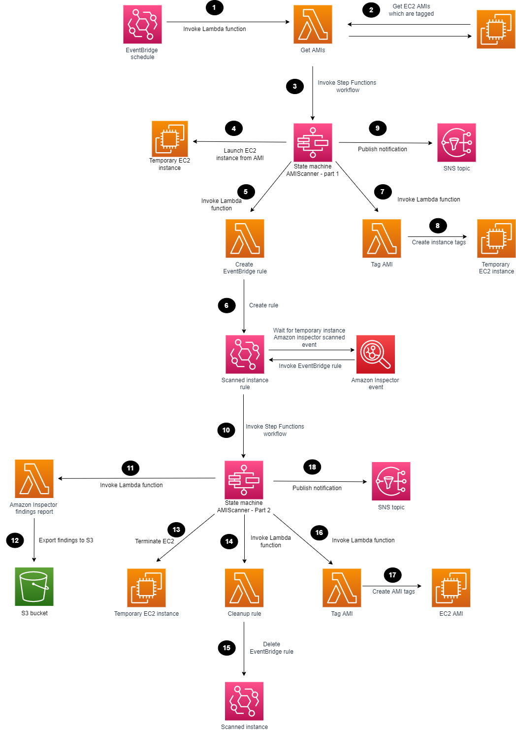
Cloud-closer sessions – We’ll discuss how AWS is bringing the cloud closer to metro areas and telco networks. Services such as AWS Local Zones, AWS Outposts family, and AWS Wavelength bring the power of cloud compute and storage to the edge of 5G networks, unlocking more performant mobile experiences. We’ll highlight new and innovative use cases, including Norton LifeLock, Electronic Arts, and Epic Games, who have taken advantage of the operational consistency between AWS Regions and the edge. Also you can learn how to deploy in hybrid cloud scenarios in on-premises locations, such as examples from MindBody and ElToro through Onica, and more customer cases.

On-premises sessions – Learn about our options to bring AWS Cloud to your data centers and on-premises locations for a truly consistent experience across your environments. We will review real-world examples of how AWS hybrid and edge services enable local processing of data for faster response time and faster decision-making. Also, we will share how Toyota takes advantage of hybrid options from Amazon ECS and Amazon EKS to use familiar management tools across your environments to successfully modernize your applications. You can learn how to meet your on-premises regulatory requirements and real-world scenarios effectively in critical aspects of digital sovereignty and data residency.

Rugged edge sessions – You will learn about AWS services to support rugged, mobile, and disconnected edge, such as AWS Snow Family to enable organizations to deploy compute workloads in locations with denied, disrupted, intermittent, and limited (DDIL) connectivity. Learn how DDR.Live deployed their own 4G/LTE or 5G private network using AWS Private 5G for live events in the place with limited wireless connection. We will discuss the top use cases, such as deploying a pre-trained object detection model and architecting applications at the edge. Finally, we will discuss the benefits and requirements of operating at the edge with Holger Mueller, vice president and principal analyst, Constellation Research, Inc.

IoT panel discussion – We will discuss from panelist of AWS IoT customers and industry experts on their innovation journey. Join us to see how EuroTech brought to market a set of devices and services that improve operational efficiencies with connectivity at the edge. You’ll also hear how Wallbox, an Electric Vehicle charging company, reduced their operational costs and scaled efficiently with AWS IoT services.

Multicloud sessions – AWS has the tools to help you run and support your multicloud operations in the areas of governance, ops management, observability, and more. We will discuss common challenges in hybrid and multicloud environments and how AWS helps you manage, operate, and automate your processes. We’ll also talk about how Rackspace used AWS Systems Manager for instance patching across hybrid and multicloud environments, automating their infrastructure management across cloud providers.

This event is for any customer and builder who is eager to learn more about hybrid cloud, edge computing, IoT, networking, content delivery, and 5G. We’ll cover how you can support applications that need to remain on premises or at the edge due to low latency, local data processing, or data residency requirements.

To learn more details, see the event schedule, and register for AWS Hybrid Cloud & Edge Day, go to the event page.

Channy

How to scan EC2 AMIs using Amazon Inspector

Post Syndicated from Luke Notley original https://aws.amazon.com/blogs/security/how-to-scan-ec2-amis-using-amazon-inspector/

Amazon Inspector is an automated vulnerability management service that continually scans Amazon Web Services (AWS) workloads for software vulnerabilities and unintended network exposure. Amazon Inspector supports vulnerability reporting and deep inspection of Amazon Elastic Compute Cloud (Amazon EC2) instances, container images stored in Amazon Elastic Container Registry (Amazon ECR), and AWS Lambda functions. Operating system and programming language support is extensive, ranging from Bottlerocket to Windows Server.

Many customers use Amazon EC2 Auto Scaling groups as part of their resilience and scaling architecture for their workloads. With Auto Scaling groups, you can scale and deploy rapidly by using Amazon Machine Images (AMIs). However, AMIs within your environment can quickly become outdated as new vulnerabilities are discovered. A security best practice is to perform routine vulnerability assessments of your AMIs to identify whether newfound vulnerabilities apply to them. If you identify a vulnerability, you can update the AMI with the appropriate security patches, test the AMI in lower environments, and deploy the updated AMI in your environment. At this time, Amazon Inspector only supports scanning of running EC2 instances.

In this blog post, we’ll share a solution that you can use with Amazon EventBridge, AWS Lambda, AWS Step Functions, Amazon Simple Notification Service (Amazon SNS)­­, and Amazon Simple Storage Service (Amazon S3) to scan AMIs and generate Amazon Inspector finding reports to help ensure that your AMIs are scanned for known vulnerabilities and updated prior to deployment. Then, we will show you how to periodically scan selected EC2 AMIs based on a tagging strategy, and take automated actions.

Prerequisites

The solution provided in this post has a number of items that you will need to review and address before you deploy the solution:

  1. Make sure that the AMI to be scanned by Amazon Inspector is based from one of the operating systems that AWS supports for EC2 scanning.
  2. To successfully complete a scan, Amazon Inspector requires the EC2 instance to be a managed instance in AWS Systems Manager that has the Systems Manager Agent installed and running, and has an attached AWS Identity and Access Management (IAM) instance profile that allows Systems Manager to manage the instance. For more information, see Scanning Amazon EC2 instances with Amazon Inspector.
  3. If you use customer managed keys to encrypt Amazon Elastic Block Store (Amazon EBS) volumes and you have a default EC2 configuration set to encrypt EBS volumes, you will need to configure additional key policy permissions. For the customer managed key that encrypts EBS volumes, add the following example policy statement to the key policy. Make sure to replace <111122223333> with your own AWS account ID.
    {
                "Sid": "Allow use of the key by AMI Scanner State Machine",
                "Effect": "Allow",
                "Principal": {
                    "AWS": "arn:aws:iam:: <111122223333>:role/service-role/AMIScanner-Statemachine-role"
                },
                "Action": [
                    "kms:Encrypt",
                    "kms:Decrypt",
                    "kms:ReEncrypt*",
                    "kms:GenerateDataKey*",
                    "kms:DescribeKey"
                ],
                "Resource": "*"
            },

    If you don’t add this additional policy, the Step Functions state machine won’t allow the EC2 instances to launch. For more information, see Key policy sections that allow access to the customer managed key.

  4. The solution in this blog post requires that you activate Amazon Inspector in your AWS account. If you haven’t activated Amazon Inspector yet, learn more about the free trial and pricing, and follow the steps in the Amazon Inspector documentation to set up the service and start monitoring your account. Alternatively, you can activate Amazon Inspector by using the AWS Command Line Interface (AWS CLI) and this GitHub example.

Solution overview and architecture

In this solution, you will use the follow AWS services and features:

  • Task orchestration
    • AWS Step Functions state machine workflows are used in this solution to verify that conditions are successfully validated before moving to the next task. This helps ensure that the Amazon Inspector scanning of the temporary instance launched in the first state machine is completed before the second state machine starts. This can help reduce the overall cost of the solution and can help prevent the first state machine from reaching state transition limitations.
    • Lambda functions handle the logic for retrieving AMIs to be scanned, launching temporary instances, creating Amazon EventBridge rules, tagging AMIs, and exporting Amazon Inspector reports to Amazon S3.
  • AMI tagging
    • To use this solution, you need to tag the AMIs that Amazon Inspector will scan, because a Lambda function will use these tags to start the solution orchestration. For this post, we use the tag InspectorScan with a value of true. With AMI tagging, you can configure automated processes as part of your deployment pipelines to implement the tagging.
  • Storage of exported Amazon Inspector findings
    • Amazon S3 helps you store the exported Amazon Inspector findings report and use them in a standardized format for multiple use cases across AWS services, or use Amazon Athena to query the reports, which we will cover later in the post. Each scanned report is stored in the S3 bucket and is named in the form AMI-NAME/guid.JSON or AMI-NAME/guid.CSV, depending on the export format that you specify.
    • You can also use S3 event notifications to alert different operational teams that there are Amazon Inspector scan results that require review.
  • Encryption of Amazon Inspector findings reports
    • AWS Key Management Service (AWS KMS) is used to encrypt the findings report. The AWS KMS key used must be a customer managed, symmetric KMS encryption key, and importantly, the key must be in the same AWS Region as the S3 bucket that you configured to store the report. The solution in this post creates a new KMS key, as well as a key policy that is configured to grant permissions for Amazon Inspector to use the key.
  • Event tracking and scheduling
    • This solution uses an Amazon EventBridge rule to listen for completed Amazon Inspector scan events for each temporary EC2 instance launch. When the EventBridge rule finds a matched event, the rule passes the required parameters and invokes the second Step Functions state machine. The event pattern used in this solution uses the following format:
      	{
      			"source": ["aws.inspector2"],
      			"detail-type": ["Inspector2 Scan"],
      			"resources": ["i-abcdef01234567890"]
      		}

    • You can schedule the AMI scanning by using an EventBridge rule that invokes a Lambda function that runs on a schedule. The Lambda function uses a cron expression to occur weekly. You can configure this parameter according to your requirements. Initially, this rule will be disabled to allow you to configure and enable the rule at a later stage.
    • Amazon SNS sends notifications during the AMI scanning solution process. From the SNS topic, you can configure different subscriptions, depending on your preferred use case and environment. An example of a subscription could be a shared mailbox email address for the security team or incident ticketing system.

Figure 1 shows the solution architecture.

Figure 1: Amazon Inspector scanning of an AMI

Figure 1: Amazon Inspector scanning of an AMI

The high-level workflow of the solution is as follows:

  1. You can use EventBridge to create a scheduled rule to invoke a Lambda function. You can set the rule for daily, weekly, or monthly, depending on your use case.
  2. The Lambda function searches for AMIs with the appropriate tags and passes these as parameters to the Step Functions workflow.
  3. The first Step Functions state machine is invoked for each AMI to be scanned.
  4. The first Step Functions workflow deploys a temporary EC2 instance from the AMI that is defined.
  5. A Lambda function is invoked to create an EventBridge rule.
  6. An EventBridge rule is created to listen for the successful Amazon Inspector scanned event of the temporary EC2 instance.
  7. A Lambda function is invoked to tag the EC2 instance.
  8. The temporary EC2 instance is tagged, showing Amazon Inspector that scanning is in progress.
  9. The first Step Functions workflow sends a notification to an SNS topic.
  10. The EventBridge rule parses the required parameters and invokes the second Step Functions state machine.
  11. A Lambda function is invoked to generate an Amazon Inspector report and export the findings to an S3 bucket.
  12. The scanned Amazon Inspector AMI results are saved to an S3 bucket.
  13. The Step Functions workflow terminates the temporary EC2 instance that can reduce cost and clean up the process.
  14. A Lambda function is invoked to delete the temporary EventBridge rule.
  15. The temporary EventBridge rule and targets are deleted.
  16. A Lambda function is invoked to tag the AMI.
  17. The scanned AMI is updated with tagging metadata.
  18. The second Step Functions workflow sends a final notification to an SNS topic.

Deploy the solution

The solution will be deployed with the scheduled rule in Amazon EventBridge disabled to allow you to create your tagging strategy and to familiarize yourself with the solution. Later in this post, we’ll cover how to enable the Amazon EventBridge scheduled rule.

Step 1: Deploy the CloudFormation template

For this next step, make sure that you deploy the CloudFormation template provided for multi-AMI scanning in the AWS account and Region where you want to test this solution.

To deploy the CloudFormation template

  1. Choose the following Launch Stack button to launch a CloudFormation stack in your account. Note that the stack will launch in the N. Virginia (us-east-1) Region. To deploy this solution into other AWS Regions, download the solution’s CloudFormation template, modify it, and deploy it to the selected Region.

    Select this image to open a link that starts building the CloudFormation stack

    Make sure that you configure the following parameters in the CloudFormation template so that it deploys successfully:

    • AMITagName — The AMI tag name to check if the AMI should be scanned by Amazon Inspector.
    • AMITagValue — The AMI tag value to check if the AMI should be scanned by Amazon Inspector.
    • InspectorReportFormat — The report format, which can be either CSV or JSON.
    • InstanceSubnetID — The subnet ID to launch the temporary EC2 instance into.
    • InstanceType — The instance type to deploy the AMI to for temporary scanning purposes.
    • KmsKeyAdministratorRole — The existing IAM role that needs to have administrator access to the KMS key created for the solution. This key provides access to encrypt and decrypt the Amazon Inspector report.
    • S3ReportBucketName — The name of the S3 bucket to be created.
    • SnsTopic — The name of the new SNS topic to be created. This name defines the SNS topic that notifications are published to.
  2. Review the stack name and the parameters for the template.
  3. On the Quick create stack screen, scroll to the bottom and select I acknowledge that AWS CloudFormation might create IAM resources.
  4. Choose Create stack. The deployment of the CloudFormation stack will take 3–4 minutes.

After the CloudFormation stack has deployed successfully, you can use the deployed solution.

Step 2: Manually run the first Step Functions workflow

The first Step Functions state machine requires parameters to be passed in; the SingleAMI Lambda function accomplishes this. You can start the Lambda function by creating a test event and passing the correct JSON text and parameters. The following parameters are available in the output section of the CloudFormation stack that the solution deployed:

  • AmiId — The ID of the AMI to be used for deploying the EC2 instance. This is the EC2 AMI to be scanned.
  • EC2InstanceProfile — The Amazon Resource Name (ARN) of the EC2 instance profile that the CloudFormation stack created.
  • InstanceType — The type of EC2 instance to use for deployment.
  • KmsKeyName — The ARN of the KMS key to be used for encrypting and decrypting the Amazon Inspector report that the CloudFormation stack created.
  • S3Bucket — The name of the S3 bucket to which the Amazon Inspector reports will be exported. The S3 bucket was created previously by the CloudFormation stack.
  • S3ReportFormat — The report format that Amazon Inspector will use to export the findings report; either the JSON or the CSV format is valid.
  • SnsTopc — The ARN of the SNS topic to which notifications will be sent. This SNS topic was created previously by the CloudFormation stack.
  • StateMachineArn — The ARN of the first Step Functions state machine, which the Lambda function will run first.
  • SubnetId — The ID of the VPC subnet to which the EC2 instance will be attached and launched into. This is a required parameter and could be a subnet that is created specifically for this scanning purpose.

The following is an example parameter configuration and JSON that you can use to run the Lambda function. Make sure to replace each <user input placeholder> with your own information.

{
"AmiId" : "<AMI-ABCDEF01234567890>",
"Ec2InstanceProfile" : "arn:aws:iam::<111122223333>:instance-profile/Ec2InstanceLaunchRole",
"InstanceType" : "t3.medium",
"KMSKeyName" : "arn:aws:kms:region-name:<111122223333>:key/<a1b2c3d4-5678-90ab-cdef-EXAMPLE11111>",
"S3Bucket" : "<DOC-EXAMPLE-BUCKET-111122223333>",
"S3ReportFormat" : "CSV",
"SnsTopic" : "arn:aws:sns:region-name-2:<111122223333>:InspectorScanner",
"StateMachine": "arn:aws:states:region-name:<111122223333>:stateMachine:AMIScanner-Part1-LaunchEC2",
"SubnetId" : "<SUBNET-ABCDEF01234567890>"
}

After the first state machine is finished, the EventBridge rule listens for the successful Amazon Inspector scan event. An SNS notification is sent, similar to the following.


{"AWS Inspector AMI Scan status":"EC2 instance","For AMI":"ami-abcdef01234567890","Temporarily launched AMI using instance":"i-abcdef01234567890"}

After Amazon Inspector has finished scanning the EC2 instance, and the second state machine completes successfully, the Amazon Inspector finding report appears in the S3 bucket and notifications appear on the SNS topic that was created. The following is an example of an SNS notification.


{"AWS Inspector AMI Scan completed":"Successfully","For AMI":"ami-abcdef01234567890","AWS Inspector report located at S3 Bucket":"DOC-EXAMPLE-BUCKET-111122223333","Temporarily launched AMI using instance":"i-abcdef01234567890"}

Enable scheduled scanning

You can enable the EventBridge scheduled rule to handle multiple AMIs and automatic scheduling. The scheduled rule invokes a Lambda function on a scheduled basis that identifies AMIs with the appropriate tags and passes parameters to the Step Functions workflow.

To enable the rule

  • In the EventBridge rules console, navigate to AMIScanner-ScheduledSolutionTask, and choose Enable.
    Figure 2: Enable Amazon EventBridge scheduled rule

    Figure 2: Enable Amazon EventBridge scheduled rule

Extend the solution

With Amazon Athena, you can run SQL queries on raw data that is stored in S3 buckets. The Amazon Inspector reports are exported to S3, and you can query the data and create tables by using AWS Glue crawlers. To make sure that AWS Glue can crawl the S3 data, you need to add the role that you create for AWS Glue to the AWS KMS key permissions, so that AWS Glue can decrypt the S3 data. The following is an example policy JSON that you can update. Make sure to replace the AWS account ID <111122223333> and S3 bucket name <DOC-EXAMPLE-BUCKET-111122223333> with your own information.

{
"Sid": "Allow the AWS Glue crawler usage of the KMS key",
"Effect": "Allow",
"Principal": {
"AWS": "arn:aws:iam::<111122223333>:role/service-role/AWSGlueServiceRole-S3InspectorReports"
},
"Action": [
"kms:Decrypt",
"kms:GenerateDataKey*"
],
"Resource": "arn:aws:s3:::<DOC-EXAMPLE-BUCKET-111122223333>"
},

After an AWS Glue Data Catalog has been built, you can run the crawler on a scheduled basis to help keep the catalog up to date with the latest Amazon Inspector findings as they are exported into the S3 bucket.

Using Amazon Athena, you can run queries against the Amazon Inspector reports to generate output data that is relevant to your environment. For example, to list the AMIs that are affected by high-severity findings, you can run the following SQL query. Make sure to replace <DOC-EXAMPLE-BUCKET-111122223333> with your own information.

SELECT DISTINCT partition_0 from "<DOC-EXAMPLE-BUCKET-111122223333>" where severity='HIGH'

With the results, you can use AWS Systems Manager to update the relevant AMIs to include the latest patches and update the launch template used in your Auto Scaling groups.

To further extend this solution, you can also use Amazon QuickSight to visualize the data by connecting to the AWS Glue table and producing dashboards for consumption.

Conclusion

By performing security assessments of your AMIs on a regular basis, you can gain greater visibility and control over the security of your EC2 instances that are created from those AMIs. In this blog post, you learned how to set up AMI vulnerability assessments, and how the results of these continuous vulnerability assessments can help you keep your environment up to date with security patches. For additional hands-on walkthroughs for Amazon Inspector, see Amazon Inspector workshops. You can find the code for this blog post in the inspector-ami-scanning-solution GitHub repository.

 
If you have feedback about this post, submit comments in the Comments section below. If you have questions about this post, contact AWS Support.

Want more AWS Security news? Follow us on Twitter.

Luke Notley

Luke Notley

Luke is a Senior Solutions Architect with Amazon Web Services and is based in Western Australia. Luke has a passion for helping customers connect business outcomes with technology and assisting customers throughout their cloud journey, helping them design scalable, flexible, and resilient architectures. In his spare time, he enjoys traveling, coaching basketball teams, and DJing.

Microservices discovery using Amazon EC2 and HashiCorp Consul

Post Syndicated from Marine Haddad original https://aws.amazon.com/blogs/architecture/microservices-discovery-using-amazon-ec2-and-hashicorp-consul/

These days, large organizations typically have microservices environments that span across cloud platforms, on-premises data centers, and colocation facilities. The reasons for this vary but frequently include latency, local support structures, and historic architectural decisions. However, due to the complex nature of these environments, efficient mechanisms for service discovery and configuration management must be implemented to support operations at scale. This is an issue also faced by Nomura.

Nomura is a global financial services group with an integrated network spanning over 30 countries and regions. By connecting markets East & West, Nomura services the needs of individuals, institutions, corporates, and governments through its three business divisions: Retail, Investment Management, and Wholesale (Global Markets and Investment Banking). E-Trading Strategy Foreign Exchange sits within Global Markets, and focuses on all quantitative analysis and technical aspects of electronic FX flows. The team builds out a number of innovative solutions for clients, all of which are needed to operate in an ultra-low latency environment to be competitive. The focus is to build high-quality engineered platforms that can handle all aspects of Nomura’s growing 24 hours a day, 5-and-a-half days a week FX business.

In this blog post, we share the solution we developed for Nomura and how you can build a service discovery mechanism that uses a hierarchical rule-based algorithm. We use the flexibility of Amazon Elastic Compute Cloud (Amazon EC2) and third-party software, such as SpringBoot and Consul. The algorithm supports features such as service discovery by service name, Domain Name System (DNS) latency, and custom provided tags. This can activate customers with automated deployments, since services are able to auto-discover and connect with other services. Based on provided tags, customers can implement environment boundaries so that a service doesn’t connect to an unintended service. Finally, we built a failover mechanism, so that if a service becomes unavailable, an alternative service would be provided (based on given criteria).

After reading this post, you can use the provided assets in the open source repository to deploy the solution in their sandbox environment. The Terraform and Java code that accompanies this post can be amended as needed to suit individual requirements.

Overview of solution

The solution is composed of a microservices platform that is spread over two different data centers, and a Consul cluster per data center. We use two Amazon Virtual Private Clouds (VPCs) to model geographically distributed Consul “data centers”. These VPCs are then connected via an AWS Transit Gateway. By permitting communication across the different data centers, the Consul clusters can form a wide-area network (WAN) and have visibility of service instances deployed to either. The SpringBoot microservices use the Spring Cloud Consul plugin to connect to the Consul cluster. We have built a custom configuration provider that uses Amazon EC2 instance metadata service to retrieve the configuration. The configuration provider mechanism is highly extensible, so anyone can build their own configuration provider.

The major components of this solution are:

    • Sample microservices built using Java and SpringBoot, and deployed in Amazon EC2 with one microservice instance per EC2 instance
    • A Consul cluster per Region with one Consul agent per EC2 instance
    • A custom service discovery algorithm
Multi-VPC infrastructure architecture

Figure 1. Multi-VPC infrastructure architecture

A typical flow for a microservice would be to 1/ boot up, 2/ retrieve relevant information from the EC2 Metadata Service (such as tags), and, 3/ use it to register itself with Consul. Once a service is registered with Consul it can discover services to integrate with, and it can be discovered by other services.

An important component of this service discovery mechanism is a custom algorithm that performs service discovery based on the tags created when registering the service with Consul.

Service discovery flow

Figure 2. Service discovery flow

The service flow shown in Figure 2 is as follows:

  1. The Consul agent deployed on the instance registers to the local Consul cluster, and the service registers to its Consul agent.
  2. The Trading service looks up for available Pricer services via API calls.
  3. The Consul agent returns the list of available Pricer services, so that the Trading service can query a Pricer service.

Walkthrough

Following are the steps required to deploy this solution:

  • Provision the infrastructure using Terraform. The application .jar file and the Consul configuration are deployed as part of it.
  • Test the solution.
  • Clean up AWS resources.

The steps are detailed in the next section, and the code can be found in this GitHub repository.

Prerequisites

Deployment steps

Note: The default AWS Region used in this deployment is ap-southeast-1. If you’re working in a different AWS Region, make sure to update it.

Clone the repository

First, clone the repository that contains all the deployment assets:

git clone https://github.com/aws-samples/geographical-hierarchical-service-lookup-with-consul-on-aws

Build Amazon Machine Images (AMIs)

1. Build the Consul Server AMI in AWS

Go to the ~/deployment/scripts/amis/consul-server/ directory and build the AMI by running:

packer build .

The output should look like this:

==>  Builds finished. The artifacts of successful builds are:

-->  amazon-ebs.ubuntu20-ami: AMIs were created:

ap-southeast-1: ami-12345678910

Make a note of the AMI ID. This will be used as part of the Terraform deployment.

2. Build the Consul Client AMI in AWS

Go to ~/deployment/scripts/amis/consul-client/ directory and build the AMI by running:

packer build .

The output should look like this:

==> Builds finished. The artifacts of successful builds are:

--> amazon-ebs.ubuntu20-ami: AMIs were created:

ap-southeast-1: ami-12345678910

Make a note of the AMI ID. This will be used as part of the Terraform deployment.

Prepare the deployment

There are a few steps that must be accomplished before applying the Terraform configuration.

1. Update deployment variables

    • In a text editor, go to directory ~/deployment/
    • Edit the variable file template.var.tfvars.json by adding the variables values, including the AMI IDs previously built for the Consul Server and Client

Note: The key pair name should be entered without the “.pem” extension.

2. Place the application file .jar in the root folder ~/deployment/

Deploy the solution

To deploy the solution, run the following commands from the terminal:

export  VAR_FILE=template.var.tfvars.json

terraform init && terraform plan --var-file=$VAR_FILE -out plan.out

terraform apply plan.out

Validate the deployment

All the EC2 instances have been deployed with AWS Systems Manager access, so you can connect privately to the terminal using the AWS Systems Manager Session Manager feature.

To connect to an instance:

1. Select an instance

2. Click Connect

3. Go to Session Manager tab

Using Session Manager, connect to one of the Consul servers and run the following commands:

consul members

This command shows you the list of all Consul servers and clients connected to this cluster.

consul members -wan

This command shows you the list of all Consul servers connected to this WAN environment.

To see the Consul User Interface:

1. Open your terminal and run:

aws ssm start-session --target <instanceID> --document-name AWS-StartPortForwardingSession --parameters '{"portNumber":["8500"],"localPortNumber":["8500"]}' --region <region>

Where instanceID is the AWS Instance ID of one of the Consul servers, and Region is the AWS Region.

Using System Manager Port Forwarding allows you to connect privately to the instance via a browser.

2. Open a browser and go to http://localhost:8500/ui

3. Find the Management Token ID in AWS Secrets Manager in the AWS Management Console

4. Login to the Consul UI using the Management Token ID

Test the solution

Connect to the trading instance and query the different services:

curl http://localhost:9090/v1/discover/service/pricer

curl http://localhost:9090/v1/discover/service/static-data

This deployment assumes that the Trading service queries the Pricer and Static-Data services, and that services are returned based on an order of precedence (see Table 1 following):

Service Precedence Customer Cluster Location Environment
TRADING 1 ACME ALPHA DC1 DEV
PRICER 1 ACME ALPHA DC1 DEV
PRICER 2 ACME ALPHA DC2 DEV
PRICER 3 ACME BETA DC1 DEV
PRICER 4 ACME BETA DC2 DEV
PRICER 5 SHARED ALPHA DC1 DEV
PRICER 6 SHARED ALPHA DC2 DEV
STATIC-DATA 1 SHARED SHARED DC1 DEV
STATIC-DATA 2 SHARED SHARED DC2 DEV
STATIC-DATA 2 SHARED BETA DC2 DEV
STATIC-DATA 2 SHARED GAMMA DC2 DEV
STATIC-DATA -1 STARK ALPHA DC1 DEV
STATIC-DATA -1 ACME BETA DC2 PROD

Table 1. Service order of precedence

To test the solution, switch on and off services in the AWS Management Console and repeat Trading queries to look at where the traffic is being redirected.

Cleaning up

To avoid incurring future charges, delete the solution from ~/deployment/ in the terminal:

terraform destroy --var-file=$VAR_FILE

Conclusion

In this post, we outlined the prevalent challenge of complex globally distributed microservice architectures. We demonstrated how customers can build a hierarchical service discovery mechanism to support such an environment using a combination of Amazon EC2 service and third-party software such as SpringBoot and Consul. Use this to test this solution into your sandbox environment and to see if it could bring the answer to your current challenge.

Additional resources:

How to deploy workloads in a multicloud environment with AWS developer tools

Post Syndicated from Brent Van Wynsberge original https://aws.amazon.com/blogs/devops/how-to-deploy-workloads-in-a-multicloud-environment-with-aws-developer-tools/

As organizations embrace cloud computing as part of “cloud first” strategy, and migrate to the cloud, some of the enterprises end up in a multicloud environment.  We see that enterprise customers get the best experience, performance and cost structure when they choose a primary cloud provider. However, for a variety of reasons, some organizations end up operating in a multicloud environment. For example, in case of mergers & acquisitions, an organization may acquire an entity which runs on a different cloud platform, resulting in the organization operating in a multicloud environment. Another example is in the case where an ISV (Independent Software Vendor) provides services to customers operating on different cloud providers. One more example is the scenario where an organization needs to adhere to data residency and data sovereignty requirements, and ends up with workloads deployed to multiple cloud platforms across locations. Thus, the organization ends up running in a multicloud environment.

In the scenarios described above, one of the challenges organizations face operating such a complex environment is managing release process (building, testing, and deploying applications at scale) across multiple cloud platforms. If an organization’s primary cloud provider is AWS, they may want to continue using AWS developer tools to deploy workloads in other cloud platforms. Organizations facing such scenarios can leverage AWS services to develop their end-to-end CI/CD and release process instead of developing a release pipeline for each platform, which is complex, and not sustainable in the long run.

In this post we show how organizations can continue using AWS developer tools in a hybrid and multicloud environment. We walk the audience through a scenario where we deploy an application to VMs running on-premises and Azure, showcasing AWS’ hybrid and multicloud DevOps capabilities.

Solution and scenario overview

In this post we’re demonstrating the following steps:

  • Setup a CI/CD pipeline using AWS CodePipeline, and show how it’s run when application code is updated, and checked into the code repository (GitHub).
  • Check out application code from the code repository, and use an IDE (Visual Studio Code) to make changes, and check-in the code to the code repository.
  • Check in the modified application code to automatically run the release process built using AWS CodePipeline. It makes use of AWS CodeBuild to retrieve the latest version of code from code repository, compile it, build the deployment package, and test the application.
  • Deploy the updated application to VMs across on-premises, and Azure using AWS CodeDeploy.

The high-level solution is shown below. This post does not show all of the possible combinations and integrations available to build the CI/CD pipeline. As an example, you can integrate the pipeline with your existing tools for test and build such as Selenium, Jenkins, SonarQube etc.

This post focuses on deploying application in a multicloud environment, and how AWS Developer Tools can support virtually any scenario or use case specific to your organization. We will be deploying a sample application from this AWS tutorial to an on-premises server, and an Azure Virtual Machine (VM) running Red Hat Enterprise Linux (RHEL). In future posts in this series, we will cover how you can deploy any type of workload using AWS tools, including containers, and serverless applications.

Architecture Diagram

CI/CD pipeline setup

This section describes instructions for setting up a multicloud CI/CD pipeline.

Note: A key point to note is that the CI/CD pipeline setup, and related sub-sections in this post, are a one-time activity, and you’ll not need to perform these steps every time an application is deployed or modified.

Install CodeDeploy agent

The AWS CodeDeploy agent is a software package that is used to execute deployments on an instance. You can install the CodeDeploy agent on an on-premises server and Azure VM by either using the command line, or AWS Systems Manager.

Setup GitHub code repository

Setup GitHub code repository using the following steps:

  1. Create a new GitHub code repository or use a repository that already exists.
  2. Copy the Sample_App_Linux app (zip) from Amazon S3 as described in Step 3 of Upload a sample application to your GitHub repository tutorial.
  3. Commit the files to code repository
    git add .
    git commit -m 'Initial Commit'
    git push

You will use this repository to deploy your code across environments.

Configure AWS CodePipeline

Follow the steps outlined below to setup and configure CodePipeline to orchestrate the CI/CD pipeline of our application.

  1. Navigate to CodePipeline in the AWS console and click on ‘Create pipeline’
  2. Give your pipeline a name (eg: MyWebApp-CICD) and allow CodePipeline to create a service role on your behalf.
  3. For the source stage, select GitHub (v2) as your source provide and click on the Connect to GitHub button to give CodePipeline access to your git repository.
  4. Create a new GitHub connection and click on the Install a new App button to install the AWS Connector in your GitHub account.
  5. Back in the CodePipeline console select the repository and branch you would like to build and deploy.

Image showing the configured source stage

  1. Now we create the build stage; Select AWS CodeBuild as the build provider.
  2. Click on the ‘Create project’ button to create the project for your build stage, and give your project a name.
  3. Select Ubuntu as the operating system for your managed image, chose the standard runtime and select the ‘aws/codebuild/standard’ image with the latest version.

Image showing the configured environment

  1. In the Buildspec section select “Insert build commands” and click on switch to editor. Enter the following yaml code as your build commands:
version: 0.2
phases:
    build:
        commands:
            - echo "This is a dummy build command"
artifacts:
    files:
        - "*/*"

Note: you can also integrate build commands to your git repository by using a buildspec yaml file. More information can be found at Build specification reference for CodeBuild.

  1. Leave all other options as default and click on ‘Continue to CodePipeline’

Image showing the configured buildspec

  1. Back in the CodePipeline console your Project name will automatically be filled in. You can now continue to the next step.
  2. Click the “Skip deploy stage” button; We will create this in the next section.
  3. Review your changes and click “Create pipeline”. Your newly created pipeline will now build for the first time!

Image showing the first execution of the CI/CD pipeline

Configure AWS CodeDeploy on Azure and on-premises VMs

Now that we have built our application, we want to deploy it to both the environments – Azure, and on-premises. In the “Install CodeDeploy agent” section we’ve already installed the CodeDeploy agent. As a one-time step we now have to give the CodeDeploy agents access to the AWS environment.  You can leverage AWS Identity and Access Management (IAM) Roles Anywhere in combination with the code-deploy-session-helper to give access to the AWS resources needed.
The IAM Role should at least have the AWSCodeDeployFullAccess AWS managed policy and Read only access to the CodePipeline S3 bucket in your account (called codepipeline-<region>-<account-id>) .

For more information on how to setup IAM Roles Anywhere please refer how to extend AWS IAM roles to workloads outside of AWS with IAM Roles Anywhere. Alternative ways to configure access can be found in the AWS CodeDeploy user guide. Follow the steps below for instances you want to configure.

  1. Configure your CodeDeploy agent as described in the user guide. Ensure the AWS Command Line Interface (CLI) is installed on your VM and execute the following command to register the instance with CodeDeploy.
    aws deploy register-on-premises-instance --instance-name <name_for_your_instance> --iam-role-arn <arn_of_your_iam_role>
  1. Tag the instance as follows
    aws deploy add-tags-to-on-premises-instances --instance-names <name_for_your_instance> --tags Key=Application,Value=MyWebApp
  2. You should now see both instances registered in the “CodeDeploy > On-premises instances” panel. You can now deploy application to your Azure VM and on premises VMs!

Image showing the registered instances

Configure AWS CodeDeploy to deploy WebApp

Follow the steps mentioned below to modify the CI/CD pipeline to deploy the application to Azure, and on-premises environments.

  1. Create an IAM role named CodeDeployServiceRole and select CodeDeploy > CodeDeploy as your use case. IAM will automatically select the right policy for you. CodeDeploy will use this role to manage the deployments of your application.
  2. In the AWS console navigate to CodeDeploy > Applications. Click on “Create application”.
  3. Give your application a name and choose “EC2/On-premises” as the compute platform.
  4. Configure the instances we want to deploy to. In the detail view of your application click on “Create deployment group”.
  5. Give your deployment group a name and select the CodeDeployServiceRole.
  6. In the environment configuration section choose On-premises Instances.
  7. Configure the Application, MyWebApp key value pair.
  8. Disable load balancing and leave all other options default.
  9. Click on create deployment group. You should now see your newly created deployment group.

Image showing the created CodeDeploy Application and Deployment group

  1. We can now edit our pipeline to deploy to the newly created deployment group.
  2. Navigate to your previously created Pipeline in the CodePipeline section and click edit. Add the deploy stage by clicking on Add stage and name it Deploy. Aftewards click Add action.
  3. Name your action and choose CodeDeploy as your action provider.
  4. Select “BuildArtifact” as your input artifact and select your newly created application and deployment group.
  5. Click on Done and on Save in your pipeline to confirm the changes. You have now added the deploy step to your pipeline!

Image showing the updated pipeline

This completes the on-time devops pipeline setup, and you will not need to repeat the process.

Automated DevOps pipeline in action

This section demonstrates how the devops pipeline operates end-to-end, and automatically deploys application to Azure VM, and on-premises server when the application code changes.

  1. Click on Release Change to deploy your application for the first time. The release change button manually triggers CodePipeline to update your code. In the next section we will make changes to the repository which triggers the pipeline automatically.
  2. During the “Source” stage your pipeline fetches the latest version from github.
  3. During the “Build” stage your pipeline uses CodeBuild to build your application and generate the deployment artifacts for your pipeline. It uses the buildspec.yml file to determine the build steps.
  4. During the “Deploy” stage your pipeline uses CodeDeploy to deploy the build artifacts to the configured Deployment group – Azure VM and on-premises VM. Navigate to the url of your application to see the results of the deployment process.

Image showing the deployed sample application


Update application code in IDE

You can modify the application code using your favorite IDE. In this example we will change the background color and a paragraph of the sample application.

Image showing modifications being made to the file

Once you’ve modified the code, save the updated file followed by pushing the code to the code repository.

git add .
git commit -m "I made changes to the index.html file "
git push

DevOps pipeline (CodePipeline) – compile, build, and test

Once the code is updated, and pushed to GitHub, the DevOps pipeline (CodePipeline) automatically compiles, builds and tests the modified application. You can navigate to your pipeline (CodePipeline) in the AWS Console, and should see the pipeline running (or has recently completed). CodePipeline automatically executes the Build and Deploy steps. In this case we’re not adding any complex logic, but based on your organization’s requirements you can add any build step, or integrate with other tools.

Image showing CodePipeline in action

Deployment process using CodeDeploy

In this section, we describe how the modified application is deployed to the Azure, and on-premises VMs.

  1. Open your pipeline in the CodePipeline console, and click on the “AWS CodeDeploy” link in the Deploy step to navigate to your deployment group. Open the “Deployments” tab.

Image showing application deployment history

  1. Click on the first deployment in the Application deployment history section. This will show the details of your latest deployment.

Image showing deployment lifecycle events for the deployment

  1. In the “Deployment lifecycle events” section click on one of the “View events” links. This shows you the lifecycle steps executed by CodeDeploy and will display the error log output if any of the steps have failed.

Image showing deployment events on instance

  1. Navigate back to your application. You should now see your changes in the application. You’ve successfully set up a multicloud DevOps pipeline!

Image showing a new version of the deployed application

Conclusion

In summary, the post demonstrated how AWS DevOps tools and services can help organizations build a single release pipeline to deploy applications and workloads in a hybrid and multicloud environment. The post also showed how to set up CI/CD pipeline to deploy applications to AWS, on-premises, and Azure VMs.

If you have any questions or feedback, leave them in the comments section.

About the Authors

Picture of Amandeep

Amandeep Bajwa

Amandeep Bajwa is a Senior Solutions Architect at AWS supporting Financial Services enterprises. He helps organizations achieve their business outcomes by identifying the appropriate cloud transformation strategy based on industry trends, and organizational priorities. Some of the areas Amandeep consults on are cloud migration, cloud strategy (including hybrid & multicloud), digital transformation, data & analytics, and technology in general.

Picture of Pawan

Pawan Shrivastava

Pawan Shrivastava is a Partner Solution Architect at AWS in the WWPS team. He focusses on working with partners to provide technical guidance on AWS, collaborate with them to understand their technical requirements, and designing solutions to meet their specific needs. Pawan is passionate about DevOps, automation and CI CD pipelines. He enjoys watching mma, playing cricket and working out in the gym.

Picture of Brent

Brent Van Wynsberge

Brent Van Wynsberge is a Solutions Architect at AWS supporting enterprise customers. He guides organizations in their digital transformation and innovation journey and accelerates cloud adoption. Brent is an IoT enthusiast, specifically in the application of IoT in manufacturing, he is also interested in DevOps, data analytics, containers, and innovative technologies in general.

Picture of Mike

Mike Strubbe

Mike is a Cloud Solutions Architect Manager at AWS with a strong focus on cloud strategy, digital transformation, business value, leadership, and governance. He helps Enterprise customers achieve their business goals through cloud expertise, coupled with strong business acumen skills. Mike is passionate about implementing cloud strategies that enable cloud transformations, increase operational efficiency and drive business value.

Optimizing GPU utilization for AI/ML workloads on Amazon EC2

Post Syndicated from Sheila Busser original https://aws.amazon.com/blogs/compute/optimizing-gpu-utilization-for-ai-ml-workloads-on-amazon-ec2/

­­­­This blog post is written by Ben Minahan, DevOps Consultant, and Amir Sotoodeh, Machine Learning Engineer.

Machine learning workloads can be costly, and artificial intelligence/machine learning (AI/ML) teams can have a difficult time tracking and maintaining efficient resource utilization. ML workloads often utilize GPUs extensively, so typical application performance metrics such as CPU, memory, and disk usage don’t paint the full picture when it comes to system performance. Additionally, data scientists conduct long-running experiments and model training activities on existing compute instances that fit their unique specifications. Forcing these experiments to be run on newly provisioned infrastructure with proper monitoring systems installed might not be a viable option.

In this post, we describe how to track GPU utilization across all of your AI/ML workloads and enable accurate capacity planning without needing teams to use a custom Amazon Machine Image (AMI) or to re-deploy their existing infrastructure. You can use Amazon CloudWatch to track GPU utilization, and leverage AWS Systems Manager Run Command to install and configure the agent across your existing fleet of GPU-enabled instances.

Overview

First, make sure that your existing Amazon Elastic Compute Cloud (Amazon EC2) instances have the Systems Manager Agent installed, and also have the appropriate level of AWS Identity and Access Management (IAM) permissions to run the Amazon CloudWatch Agent. Next, specify the configuration for the CloudWatch Agent in Systems Manager Parameter Store, and then deploy the CloudWatch Agent to our GPU-enabled EC2 instances. Finally, create a CloudWatch Dashboard to analyze GPU utilization.

Architecture Diagram depicting the integration between AWS Systems Manager with RunCommand Arguments stored in SSM Parameter Store, your Amazon GPU enabled EC2 instance with installed Amazon CloudWatch Agen­t, and Amazon CloudWatch Dashboard that aggregates and displays the ­reported metrics.

  1. Install the CloudWatch Agent on your existing GPU-enabled EC2 instances.
  2. Your CloudWatch Agent configuration is stored in Systems Manager Parameter Store.
  3. Systems Manager Documents are used to install and configure the CloudWatch Agent on your EC2 instances.
  4. GPU metrics are published to CloudWatch, which you can then visualize through the CloudWatch Dashboard.

Prerequisites

This post assumes you already have GPU-enabled EC2 workloads running in your AWS account. If the EC2 instance doesn’t have any GPUs, then the custom configuration won’t be applied to the CloudWatch Agent. Instead, the default configuration is used. For those instances, leveraging the CloudWatch Agent’s default configuration is better suited for tracking resource utilization.

For the CloudWatch Agent to collect your instance’s GPU metrics, the proper NVIDIA drivers must be installed on your instance. Several AWS official AMIs including the Deep Learning AMI already have these drivers installed. To see a list of AMIs with the NVIDIA drivers pre-installed, and for full installation instructions for Linux-based instances, see Install NVIDIA drivers on Linux instances.

Additionally, deploying and managing the CloudWatch Agent requires the instances to be running. If your instances are currently stopped, then you must start them to follow the instructions outlined in this post.

Preparing your EC2 instances

You utilize Systems Manager to deploy the CloudWatch Agent, so make sure that your EC2 instances have the Systems Manager Agent installed. Many AWS-provided AMIs already have the Systems Manager Agent installed. For a full list of the AMIs which have the Systems Manager Agent pre-installed, see Amazon Machine Images (AMIs) with SSM Agent preinstalled. If your AMI doesn’t have the Systems Manager Agent installed, see Working with SSM Agent for instructions on installing based on your operating system (OS).

Once installed, the CloudWatch Agent needs certain permissions to accept commands from Systems Manager, read Systems Manager Parameter Store entries, and publish metrics to CloudWatch. These permissions are bundled into the managed IAM policies AmazonEC2RoleforSSM, AmazonSSMReadOnlyAccess, and CloudWatchAgentServerPolicy. To create a new IAM role and associated IAM instance profile with these policies attached, you can run the following AWS Command Line Interface (AWS CLI) commands, replacing <REGION_NAME> with your AWS region, and <INSTANCE_ID> with the EC2 Instance ID that you want to associate with the instance profile:

aws iam create-role --role-name CloudWatch-Agent-Role --assume-role-policy-document  '{"Statement":{"Effect":"Allow","Principal":{"Service":"ec2.amazonaws.com"},"Action":"sts:AssumeRole"}}'
aws iam attach-role-policy --role-name CloudWatch-Agent-Role --policy-arn arn:aws:iam::aws:policy/service-role/AmazonEC2RoleforSSM
aws iam attach-role-policy --role-name CloudWatch-Agent-Role --policy-arn arn:aws:iam::aws:policy/AmazonSSMReadOnlyAccess
aws iam attach-role-policy --role-name CloudWatch-Agent-Role --policy-arn arn:aws:iam::aws:policy/CloudWatchAgentServerPolicy
aws iam create-instance-profile --instance-profile-name CloudWatch-Agent-Instance-Profile
aws iam add-role-to-instance-profile --instance-profile-name CloudWatch-Agent-Instance-Profile --role-name CloudWatch-Agent-Role
aws ec2 associate-iam-instance-profile --region <REGION_NAME> --instance-id <INSTANCE_ID> --iam-instance-profile Name=CloudWatch-Agent-Instance-Profile

Alternatively, you can attach the IAM policies to your existing IAM role associated with an existing IAM instance profile.

aws iam attach-role-policy --role-name <ROLE_NAME> --policy-arn arn:aws:iam::aws:policy/service-role/AmazonEC2RoleforSSM
aws iam attach-role-policy --role-name <ROLE_NAME> --policy-arn arn:aws:iam::aws:policy/AmazonSSMReadOnlyAccess
aws iam attach-role-policy --role-name <ROLE_NAME> --policy-arn arn:aws:iam::aws:policy/CloudWatchAgentServerPolicy
aws ec2 associate-iam-instance-profile --region <REGION_NAME> --instance-id <INSTANCE_ID> --iam-instance-profile Name=<INSTANCE_PROFILE>

Once complete, you should see that your EC2 instance is associated with the appropriate IAM role.

An Amazon EC2 Instance with the CloudWatch-Agent-Role IAM Role attached

This role should have the AmazonEC2RoleforSSM, AmazonSSMReadOnlyAccess and CloudWatchAgentServerPolicy IAM policies attached.

The CloudWatch-Agent-Role IAM Role’s attached permission policies, Amazon EC2 Role for SSM, CloudWatch Agent Server ¬Policy, and Amazon SSM Read Only Access

Configuring and deploying the CloudWatch Agent

Before deploying the CloudWatch Agent onto our EC2 instances, make sure that those agents are properly configured to collect GPU metrics. To do this, you must create a CloudWatch Agent configuration and store it in Systems Manager Parameter Store.

Copy the following into a file cloudwatch-agent-config.json:

{
    "agent": {
        "metrics_collection_interval": 60,
        "run_as_user": "cwagent"
    },
    "metrics": {
        "aggregation_dimensions": [
            [
                "InstanceId"
            ]
        ],
        "append_dimensions": {
            "AutoScalingGroupName": "${aws:AutoScalingGroupName}",
            "ImageId": "${aws:ImageId}",
            "InstanceId": "${aws:InstanceId}",
            "InstanceType": "${aws:InstanceType}"
        },
        "metrics_collected": {
            "cpu": {
                "measurement": [
                    "cpu_usage_idle",
                    "cpu_usage_iowait",
                    "cpu_usage_user",
                    "cpu_usage_system"
                ],
                "metrics_collection_interval": 60,
                "resources": [
                    "*"
                ],
                "totalcpu": false
            },
            "disk": {
                "measurement": [
                    "used_percent",
                    "inodes_free"
                ],
                "metrics_collection_interval": 60,
                "resources": [
                    "*"
                ]
            },
            "diskio": {
                "measurement": [
                    "io_time"
                ],
                "metrics_collection_interval": 60,
                "resources": [
                    "*"
                ]
            },
            "mem": {
                "measurement": [
                    "mem_used_percent"
                ],
                "metrics_collection_interval": 60
            },
            "swap": {
                "measurement": [
                    "swap_used_percent"
                ],
                "metrics_collection_interval": 60
            },
            "nvidia_gpu": {
                "measurement": [
                    "utilization_gpu",
                    "temperature_gpu",
                    "utilization_memory",
                    "fan_speed",
                    "memory_total",
                    "memory_used",
                    "memory_free",
                    "pcie_link_gen_current",
                    "pcie_link_width_current",
                    "encoder_stats_session_count",
                    "encoder_stats_average_fps",
                    "encoder_stats_average_latency",
                    "clocks_current_graphics",
                    "clocks_current_sm",
                    "clocks_current_memory",
                    "clocks_current_video"
                ],
                "metrics_collection_interval": 60
            }
        }
    }
}

Run the following AWS CLI command to deploy a Systems Manager Parameter CloudWatch-Agent-Config, which contains a minimal agent configuration for GPU metrics collection. Replace <REGION_NAME> with your AWS Region.

aws ssm put-parameter \
--region <REGION_NAME> \
--name CloudWatch-Agent-Config \
--type String \
--value file://cloudwatch-agent-config.json

Now you can see a CloudWatch-Agent-Config parameter in Systems Manager Parameter Store, containing your CloudWatch Agent’s JSON configuration.

CloudWatch-Agent-Config stored in Systems Manager Parameter Store

Next, install the CloudWatch Agent on your EC2 instances. To do this, you can leverage Systems Manager Run Command, specifically the AWS-ConfigureAWSPackage document which automates the CloudWatch Agent installation.

  1. Run the following AWS CLI command, replacing <REGION_NAME> with the Region into which your instances are deployed, and <INSTANCE_ID> with the EC2 Instance ID on which you want to install the CloudWatch Agent.
aws ssm send-command \
--query 'Command.CommandId' \
--region <REGION_NAME> \
--instance-ids <INSTANCE_ID> \
--document-name AWS-ConfigureAWSPackage \
--parameters '{"action":["Install"],"installationType":["In-place update"],"version":["latest"],"name":["AmazonCloudWatchAgent"]}'

2. To monitor the status of your command, use the get-command-invocation AWS CLI command. Replace <COMMAND_ID> with the command ID output from the previous step, <REGION_NAME> with your AWS region, and <INSTANCE_ID> with your EC2 instance ID.

aws ssm get-command-invocation --query Status --region <REGION_NAME> --command-id <COMMAND_ID> --instance-id <INSTANCE_ID>

3.Wait for the command to show the status Success before proceeding.

$ aws ssm send-command \
	 --query 'Command.CommandId' \
    --region us-east-2 \
    --instance-ids i-0123456789abcdef \
    --document-name AWS-ConfigureAWSPackage \
    --parameters '{"action":["Install"],"installationType":["Uninstall and reinstall"],"version":["latest"],"additionalArguments":["{}"],"name":["AmazonCloudWatchAgent"]}'

"5d8419db-9c48-434c-8460-0519640046cf"

$ aws ssm get-command-invocation --query Status --region us-east-2 --command-id 5d8419db-9c48-434c-8460-0519640046cf --instance-id i-0123456789abcdef

"Success"

Repeat this process for all EC2 instances on which you want to install the CloudWatch Agent.

Next, configure the CloudWatch Agent installation. For this, once again leverage Systems Manager Run Command. However, this time the AmazonCloudWatch-ManageAgent document which applies your custom agent configuration is stored in the Systems Manager Parameter Store to your deployed agents.

  1. Run the following AWS CLI command, replacing <REGION_NAME> with the Region into which your instances are deployed, and <INSTANCE_ID> with the EC2 Instance ID on which you want to configure the CloudWatch Agent.
aws ssm send-command \
--query 'Command.CommandId' \
--region <REGION_NAME> \
--instance-ids <INSTANCE_ID> \
--document-name AmazonCloudWatch-ManageAgent \
--parameters '{"action":["configure"],"mode":["ec2"],"optionalConfigurationSource":["ssm"],"optionalConfigurationLocation":["/CloudWatch-Agent-Config"],"optionalRestart":["yes"]}'

2. To monitor the status of your command, utilize the get-command-invocation AWS CLI command. Replace <COMMAND_ID> with the command ID output from the previous step, <REGION_NAME> with your AWS region, and <INSTANCE_ID> with your EC2 instance ID.

aws ssm get-command-invocation --query Status --region <REGION_NAME> --command-id <COMMAND_ID> --instance-id <INSTANCE_ID>

3. Wait for the command to show the status Success before proceeding.

$ aws ssm send-command \
    --query 'Command.CommandId' \
    --region us-east-2 \
    --instance-ids i-0123456789abcdef \
    --document-name AmazonCloudWatch-ManageAgent \
    --parameters '{"action":["configure"],"mode":["ec2"],"optionalConfigurationSource":["ssm"],"optionalConfigurationLocation":["/CloudWatch-Agent-Config"],"optionalRestart":["yes"]}'

"9a4a5c43-0795-4fd3-afed-490873eaca63"

$ aws ssm get-command-invocation --query Status --region us-east-2 --command-id 9a4a5c43-0795-4fd3-afed-490873eaca63 --instance-id i-0123456789abcdef

"Success"

Repeat this process for all EC2 instances on which you want to install the CloudWatch Agent. Once finished, the CloudWatch Agent installation and configuration is complete, and your EC2 instances now report GPU metrics to CloudWatch.

Visualize your instance’s GPU metrics in CloudWatch

Now that your GPU-enabled EC2 Instances are publishing their utilization metrics to CloudWatch, you can visualize and analyze these metrics to better understand your resource utilization patterns.

The GPU metrics collected by the CloudWatch Agent are within the CWAgent namespace. Explore your GPU metrics using the CloudWatch Metrics Explorer, or deploy our provided sample dashboard.

  1. Copy the following into a file, cloudwatch-dashboard.json, replacing instances of <REGION_NAME> with your Region:
{
    "widgets": [
        {
            "height": 10,
            "width": 24,
            "y": 16,
            "x": 0,
            "type": "metric",
            "properties": {
                "metrics": [
                    [{"expression": "SELECT AVG(nvidia_smi_utilization_gpu) FROM SCHEMA(\"CWAgent\", InstanceId) GROUP BY InstanceId","id": "q1"}]
                ],
                "view": "timeSeries",
                "stacked": false,
                "region": "<REGION_NAME>",
                "stat": "Average",
                "period": 300,
                "title": "GPU Core Utilization",
                "yAxis": {
                    "left": {"label": "Percent","max": 100,"min": 0,"showUnits": false}
                }
            }
        },
        {
            "height": 7,
            "width": 8,
            "y": 0,
            "x": 0,
            "type": "metric",
            "properties": {
                "metrics": [
                    [{"expression": "SELECT AVG(nvidia_smi_utilization_gpu) FROM SCHEMA(\"CWAgent\", InstanceId)", "label": "Utilization","id": "q1"}]
                ],
                "view": "gauge",
                "stacked": false,
                "region": "<REGION_NAME>",
                "stat": "Average",
                "period": 300,
                "title": "Average GPU Core Utilization",
                "yAxis": {"left": {"max": 100, "min": 0}
                },
                "liveData": false
            }
        },
        {
            "height": 9,
            "width": 24,
            "y": 7,
            "x": 0,
            "type": "metric",
            "properties": {
                "metrics": [
                    [{ "expression": "SEARCH(' MetricName=\"nvidia_smi_memory_used\" {\"CWAgent\", InstanceId} ', 'Average')", "id": "m1", "visible": false }],
                    [{ "expression": "SEARCH(' MetricName=\"nvidia_smi_memory_total\" {\"CWAgent\", InstanceId} ', 'Average')", "id": "m2", "visible": false }],
                    [{ "expression": "SEARCH(' MetricName=\"mem_used_percent\" {CWAgent, InstanceId} ', 'Average')", "id": "m3", "visible": false }],
                    [{ "expression": "100*AVG(m1)/AVG(m2)", "label": "GPU", "id": "e2", "color": "#17becf" }],
                    [{ "expression": "AVG(m3)", "label": "RAM", "id": "e3" }]
                ],
                "view": "timeSeries",
                "stacked": false,
                "region": "<REGION_NAME>",
                "stat": "Average",
                "period": 300,
                "yAxis": {
                    "left": {"min": 0,"max": 100,"label": "Percent","showUnits": false}
                },
                "title": "Average Memory Utilization"
            }
        },
        {
            "height": 7,
            "width": 8,
            "y": 0,
            "x": 8,
            "type": "metric",
            "properties": {
                "metrics": [
                    [ { "expression": "SEARCH(' MetricName=\"nvidia_smi_memory_used\" {\"CWAgent\", InstanceId} ', 'Average')", "id": "m1", "visible": false } ],
                    [ { "expression": "SEARCH(' MetricName=\"nvidia_smi_memory_total\" {\"CWAgent\", InstanceId} ', 'Average')", "id": "m2", "visible": false } ],
                    [ { "expression": "100*AVG(m1)/AVG(m2)", "label": "Utilization", "id": "e2" } ]
                ],
                "sparkline": true,
                "view": "gauge",
                "region": "<REGION_NAME>",
                "stat": "Average",
                "period": 300,
                "yAxis": {
                    "left": {"min": 0,"max": 100}
                },
                "liveData": false,
                "title": "GPU Memory Utilization"
            }
        }
    ]
}

2. run the following AWS CLI command, replacing <REGION_NAME> with the name of your Region:

aws cloudwatch put-dashboard \
    --region <REGION_NAME> \
    --dashboard-name My-GPU-Usage \
    --dashboard-body file://cloudwatch-dashboard.json

View the My-GPU-Usage CloudWatch dashboard in the CloudWatch console for your AWS region..

An example CloudWatch dashboard, My-GPU-Usage, showing the GPU usage metrics over time.

Cleaning Up

To avoid incurring future costs for resources created by following along in this post, delete the following:

  1. My-GPU-Usage CloudWatch Dashboard
  2. CloudWatch-Agent-Config Systems Manager Parameter
  3. CloudWatch-Agent-Role IAM Role

Conclusion

By following along with this post, you deployed and configured the CloudWatch Agent across your GPU-enabled EC2 instances to track GPU utilization without pausing in-progress experiments and model training. Then, you visualized the GPU utilization of your workloads with a CloudWatch Dashboard to better understand your workload’s GPU usage and make more informed scaling and cost decisions. For other ways that Amazon CloudWatch can improve your organization’s operational insights, see the Amazon CloudWatch documentation.

AWS Week in Review: Public Preview of Amazon DataZone and AWS DataSync Updates – April 3, 2023

Post Syndicated from Channy Yun original https://aws.amazon.com/blogs/aws/aws-week-in-review-public-preview-of-amazon-datazone-and-aws-datasync-updates-april-3-2023/

Last weekend, I enjoyed the spring vibes at Seoul Forest, a large park in the middle of Seoul city, where cherry blossoms are in full bloom.
Compared to last year, there were crowds of people, so I realized that it was really back to normal after the pandemic. I hope you all enjoy the season of spring or fall with your family.

Last Week’s Launches
Like an April Fool’s Day joke, there were 65 launches last week, far more than usual. AWS product teams are working hard with a customer obsession.

So, I had a lot of trouble choosing the important ones. Other than the ones I’ve picked out, there may be important feature releases that fit your needs. Be sure to take a look at the full launches list in the last week.

First, here is a list of the general availability of AWS services and features treated by AWS News Blog:

Let’s take a look at some launches from the last week that I want to remind you of:

The Preview of Amazon DataZone – At AWS re:Invent 2022, we preannounced Amazon DataZone, a new data management service to catalog, discover, analyze, share, and govern data between data producers and consumers in the organization. You can now try out the public preview of Amazon DataZone.

Data producers populate the business data catalog from AWS Glue Data Catalog and Amazon Redshift tables. Data consumers search for and subscribe to data assets in the data catalog and analyze with tools such as Amazon Athena query editors in the Amazon DataZone portal. To get started with Amazon DataZone, see our Quick Start Guide to include sample datasets to implement a complete use case.

AWS DataSync Supports Azure Blob Storage in PreviewAWS DataSync supports copying your object data at scale from Azure Blob Storage to AWS storage services such as Amazon S3. AWS DataSync supports all blob types within Azure Blob Storage and can also be used with Azure Data Lake Storage (ADLS) Gen 2.

In addition to Azure Blob Storage, DataSync supports Google Cloud Storage and Azure Files storage locations as well as various general storage systems and AWS storage services. To learn more, see Migrating Azure Blob Storage to Amazon S3 using AWS DataSync in the AWS Storage Blog.

On-call schedules with AWS Systems Manager Incident Manager – You can now configure or change on-call rotation schedules with a group of contacts and have 24/7 coverage and responsiveness for critical issues in the Incident Manager console.

AWS Incident Manager helps you bring the right people and information together when a critical issue is detected, activating preconfigured response plans to engage responders using SMS, phone calls, and chat channels, as well as to run AWS Systems Manager Automation runbooks. To learn how to get started with an-call schedules in Incident Manager, see our Working with on-call schedules in Incident Manager in the AWS documentation.

AWS CloudShell Colsone Toolbar – You can now use AWS Cloudshell Console Toolbar with AWS Management Console in a single view. The Console Toolbar maintains its state (e.g., open, closed) and commands will continue to run in CloudShell as you navigate between services in the Console. For example, it allows you to run a command in CloudShell and view a CloudWatch alarm in the Console at the same time.

After signing into the Console, you can access CloudShell in the lower left of the Console by selecting the CloudShell icon in the Console Toolbar.

New Features of AWS Well-Architected Tool – The Consolidated Report and Enhanced Search enable customers to quickly identify risk themes across their workloads and scale improvements across their organization. This macro-level view helps executive stakeholders understand where common issues lie and prioritize team resources to drive widespread improvement. To learn more, see AWS Well-Architected Tool Dashboard in the AWS documentation.

For a full list of AWS announcements, be sure to keep an eye on the What’s New at AWS page.

Other AWS News
Here are some other news items that you may find interesting from the last week:

Welcome to the .NET on AWS Blog – We launched a new blog channel for millions of .NET developers across the world. Blog posts will also cover built-for-the-cloud development, modernizing .NET Framework applications, and how to deploy .NET workloads on different AWS services. We will use this channel to share news on the work we’ve done with the .NET open-source community, post follow-ups from important events, and post announcements about upcoming presentations from our .NET developer advocates. To learn more, visit our .NET on AWS website and follow us on Twitter at @dotnetonAWS.

AWS Knowledge Center in AWS re:Post – You can now access trusted, authoritative articles and videos of AWS Knowledge Center on AWS re:Post to get answers to technical questions. Knowledge Center content is produced by an AWS team and covers the most frequent questions and requests from AWS customers. These articles are available in 10 localized languages: English, French, German, Italian, Japanese, Korean, Portuguese, Simplified Chinese, Spanish, and Traditional Chinese.

TF1’s FIFA Worldcup Digital Broadcasting Story – Sébastien shared an awesome story about how the French broadcaster TF1 use AWS Cloud technology and expertise to bring the FIFA World Cup to millions of people. He shared the history of redesigning its digital broadcasting architecture on AWS, testing the new platform on large-scale sporting events. For the preparation of the FIFA Worldcup event, TF1 enhanced monitoring to detect anomalies during the event and established the backup plan in a “war room” for the worst scenario. Even if you’re not a fan of football, I recommend reading the behind-the-scenes of the FIFA Worldcup Finals. It’s long but really fun!

Upcoming AWS Events
Check your calendars and sign up for these AWS-led events:

AWS re:Inforce 2023 – Now register AWS re:Inforce, in Anaheim, California, June 13–14. AWS Chief Information Security Officer CJ Moses will share the latest innovations in cloud security and what AWS Security is focused on. The breakout sessions will provide real-world examples of how security is embedded into the way businesses operate. To learn more and get the limited discount code to register, see CJ’s blog post of Gain insights and knowledge at AWS re:Inforce 2023 in the AWS Security Blog.

AWS Global Summits – Check your calendars and sign up for the AWS Summit closest to your city: Paris and Sydney (April 4), Seoul (May 3-4), Berlin and Singapore (May 4), Stockholm (May 11), Hong Kong (May 23), Amsterdam (June 1), London (June 7), Madrid (June 15), and Milano (June 22).

AWS Community Day – Join community-led conferences driven by AWS user group leaders closest to your city: Peru (April 15), Helsinki (April 20), Chicago (June 15), Philippines (June 29–30), and Munich (September 14). Recently, we are bringing together AWS user groups from around the world into Meetup Pro accounts. Find your group and its meetups in your city!

You can browse all upcoming AWS-led in-person and virtual events, and developer-focused events such as AWS DevDay.

That’s all for this week. Check back next Monday for another Week in Review!

— Channy

This post is part of our Week in Review series. Check back each week for a quick roundup of interesting news and announcements from AWS!

Serverless ICYMI Q1 2023

Post Syndicated from Julian Wood original https://aws.amazon.com/blogs/compute/serverless-icymi-q1-2023/

Welcome to the 21st edition of the AWS Serverless ICYMI (in case you missed it) quarterly recap. Every quarter, we share all the most recent product launches, feature enhancements, blog posts, webinars, live streams, and other interesting things that you might have missed!

ICYMI2023Q1

In case you missed our last ICYMI, check out what happened last quarter here.

Artificial intelligence (AI) technologies, ChatGPT, and DALL-E are creating significant interest in the industry at the moment. Find out how to integrate serverless services with ChatGPT and DALL-E to generate unique bedtime stories for children.

Example notification of a story hosted with Next.js and App Runner

Example notification of a story hosted with Next.js and App Runner

Serverless Land is a website maintained by the Serverless Developer Advocate team to help you build serverless applications and includes workshops, code examples, blogs, and videos. There is now enhanced search functionality so you can search across resources, patterns, and video content.

SLand-search

ServerlessLand search

AWS Lambda

AWS Lambda has improved how concurrency works with Amazon SQS. You can now control the maximum number of concurrent Lambda functions invoked.

The launch blog post explains the scaling behavior of Lambda using this architectural pattern, challenges this feature helps address, and a demo of maximum concurrency in action.

Maximum concurrency is set to 10 for the SQS queue.

Maximum concurrency is set to 10 for the SQS queue.

AWS Lambda Powertools is an open-source library to help you discover and incorporate serverless best practices more easily. Lambda Powertools for .NET is now generally available and currently focused on three observability features: distributed tracing (Tracer), structured logging (Logger), and asynchronous business and application metrics (Metrics). Powertools is also available for Python, Java, and Typescript/Node.js programming languages.

To learn more:

Lambda announced a new feature, runtime management controls, which provide more visibility and control over when Lambda applies runtime updates to your functions. The runtime controls are optional capabilities for advanced customers that require more control over their runtime changes. You can now specify a runtime management configuration for each function with three settings, Automatic (default), Function update, or manual.

There are three new Amazon CloudWatch metrics for asynchronous Lambda function invocations: AsyncEventsReceived, AsyncEventAge, and AsyncEventsDropped. You can track the asynchronous invocation requests sent to Lambda functions to monitor any delays in processing and take corrective actions if required. The launch blog post explains the new metrics and how to use them to troubleshoot issues.

Lambda now supports Amazon DocumentDB change streams as an event source. You can use Lambda functions to process new documents, track updates to existing documents, or log deleted documents. You can use any programming language that is supported by Lambda to write your functions.

There is a helpful blog post suggesting best practices for developing portable Lambda functions that allow you to port your code to containers if you later choose to.

AWS Step Functions

AWS Step Functions has expanded its AWS SDK integrations with support for 35 additional AWS services including Amazon EMR Serverless, AWS Clean Rooms, AWS IoT FleetWise, AWS IoT RoboRunner and 31 other AWS services. In addition, Step Functions also added support for 1000+ new API actions from new and existing AWS services such as Amazon DynamoDB and Amazon Athena. For the full list of added services, visit AWS SDK service integrations.

Amazon EventBridge

Amazon EventBridge has launched the AWS Controllers for Kubernetes (ACK) for EventBridge and Pipes . This allows you to manage EventBridge resources, such as event buses, rules, and pipes, using the Kubernetes API and resource model (custom resource definitions).

EventBridge event buses now also support enhanced integration with Service Quotas. Your quota increase requests for limits such as PutEvents transactions-per-second, number of rules, and invocations per second among others will be processed within one business day or faster, enabling you to respond quickly to changes in usage.

AWS SAM

The AWS Serverless Application Model (SAM) Command Line Interface (CLI) has added the sam list command. You can now show resources defined in your application, including the endpoints, methods, and stack outputs required to test your deployed application.

AWS SAM has a preview of sam build support for building and packaging serverless applications developed in Rust. You can use cargo-lambda in the AWS SAM CLI build workflow and AWS SAM Accelerate to iterate on your code changes rapidly in the cloud.

You can now use AWS SAM connectors as a source resource parameter. Previously, you could only define AWS SAM connectors as a AWS::Serverless::Connector resource. Now you can add the resource attribute on a connector’s source resource, which makes templates more readable and easier to update over time.

AWS SAM connectors now also support multiple destinations to simplify your permissions. You can now use a single connector between a single source resource and multiple destination resources.

In October 2022, AWS released OpenID Connect (OIDC) support for AWS SAM Pipelines. This improves your security posture by creating integrations that use short-lived credentials from your CI/CD provider. There is a new blog post on how to implement it.

Find out how best to build serverless Java applications with the AWS SAM CLI.

AWS App Runner

AWS App Runner now supports retrieving secrets and configuration data stored in AWS Secrets Manager and AWS Systems Manager (SSM) Parameter Store in an App Runner service as runtime environment variables.

AppRunner also now supports incoming requests based on HTTP 1.0 protocol, and has added service level concurrency, CPU and Memory utilization metrics.

Amazon S3

Amazon S3 now automatically applies default encryption to all new objects added to S3, at no additional cost and with no impact on performance.

You can now use an S3 Object Lambda Access Point alias as an origin for your Amazon CloudFront distribution to tailor or customize data to end users. For example, you can resize an image depending on the device that an end user is visiting from.

S3 has introduced Mountpoint for S3, a high performance open source file client that translates local file system API calls to S3 object API calls like GET and LIST.

S3 Multi-Region Access Points now support datasets that are replicated across multiple AWS accounts. They provide a single global endpoint for your multi-region applications, and dynamically route S3 requests based on policies that you define. This helps you to more easily implement multi-Region resilience, latency-based routing, and active-passive failover, even when data is stored in multiple accounts.

Amazon Kinesis

Amazon Kinesis Data Firehose now supports streaming data delivery to Elastic. This is an easier way to ingest streaming data to Elastic and consume the Elastic Stack (ELK Stack) solutions for enterprise search, observability, and security without having to manage applications or write code.

Amazon DynamoDB

Amazon DynamoDB now supports table deletion protection to protect your tables from accidental deletion when performing regular table management operations. You can set the deletion protection property for each table, which is set to disabled by default.

Amazon SNS

Amazon SNS now supports AWS X-Ray active tracing to visualize, analyze, and debug application performance. You can now view traces that flow through Amazon SNS topics to destination services, such as Amazon Simple Queue Service, Lambda, and Kinesis Data Firehose, in addition to traversing the application topology in Amazon CloudWatch ServiceLens.

SNS also now supports setting content-type request headers for HTTPS notifications so applications can receive their notifications in a more predictable format. Topic subscribers can create a DeliveryPolicy that specifies the content-type value that SNS assigns to their HTTPS notifications, such as application/json, application/xml, or text/plain.

EDA Visuals collection added to Serverless Land

The Serverless Developer Advocate team has extended Serverless Land and introduced EDA visuals. These are small bite sized visuals to help you understand concept and patterns about event-driven architectures. Find out about batch processing vs. event streaming, commands vs. events, message queues vs. event brokers, and point-to-point messaging. Discover bounded contexts, migrations, idempotency, claims, enrichment and more!

EDA-visuals

EDA Visuals

To learn more:

Serverless Repos Collection on Serverless Land

There is also a new section on Serverless Land containing helpful code repositories. You can search for code repos to use for examples, learning or building serverless applications. You can also filter by use-case, runtime, and level.

Serverless Repos Collection

Serverless Repos Collection

Serverless Blog Posts

January

Jan 12 – Introducing maximum concurrency of AWS Lambda functions when using Amazon SQS as an event source

Jan 20 – Processing geospatial IoT data with AWS IoT Core and the Amazon Location Service

Jan 23 – AWS Lambda: Resilience under-the-hood

Jan 24 – Introducing AWS Lambda runtime management controls

Jan 24 – Best practices for working with the Apache Velocity Template Language in Amazon API Gateway

February

Feb 6 – Previewing environments using containerized AWS Lambda functions

Feb 7 – Building ad-hoc consumers for event-driven architectures

Feb 9 – Implementing architectural patterns with Amazon EventBridge Pipes

Feb 9 – Securing CI/CD pipelines with AWS SAM Pipelines and OIDC

Feb 9 – Introducing new asynchronous invocation metrics for AWS Lambda

Feb 14 – Migrating to token-based authentication for iOS applications with Amazon SNS

Feb 15 – Implementing reactive progress tracking for AWS Step Functions

Feb 23 – Developing portable AWS Lambda functions

Feb 23 – Uploading large objects to Amazon S3 using multipart upload and transfer acceleration

Feb 28 – Introducing AWS Lambda Powertools for .NET

March

Mar 9 – Server-side rendering micro-frontends – UI composer and service discovery

Mar 9 – Building serverless Java applications with the AWS SAM CLI

Mar 10 – Managing sessions of anonymous users in WebSocket API-based applications

Mar 14 –
Implementing an event-driven serverless story generation application with ChatGPT and DALL-E

Videos

Serverless Office Hours – Tues 10AM PT

Weekly office hours live stream. In each session we talk about a specific topic or technology related to serverless and open it up to helping you with your real serverless challenges and issues. Ask us anything you want about serverless technologies and applications.

January

Jan 10 – Building .NET 7 high performance Lambda functions

Jan 17 – Amazon Managed Workflows for Apache Airflow at Scale

Jan 24 – Using Terraform with AWS SAM

Jan 31 – Preparing your serverless architectures for the big day

February

Feb 07- Visually design and build serverless applications

Feb 14 – Multi-tenant serverless SaaS

Feb 21 – Refactoring to Serverless

Feb 28 – EDA visually explained

March

Mar 07 – Lambda cookbook with Python

Mar 14 – Succeeding with serverless

Mar 21 – Lambda Powertools .NET

Mar 28 – Server-side rendering micro-frontends

FooBar Serverless YouTube channel

Marcia Villalba frequently publishes new videos on her popular serverless YouTube channel. You can view all of Marcia’s videos at https://www.youtube.com/c/FooBar_codes.

January

Jan 12 – Serverless Badge – A new certification to validate your Serverless Knowledge

Jan 19 – Step functions Distributed map – Run 10k parallel serverless executions!

Jan 26 – Step Functions Intrinsic Functions – Do simple data processing directly from the state machines!

February

Feb 02 – Unlock the Power of EventBridge Pipes: Integrate Across Platforms with Ease!

Feb 09 – Amazon EventBridge Pipes: Enrichment and filter of events Demo with AWS SAM

Feb 16 – AWS App Runner – Deploy your apps from GitHub to Cloud in Record Time

Feb 23 – AWS App Runner – Demo hosting a Node.js app in the cloud directly from GitHub (AWS CDK)

March

Mar 02 – What is Amazon DynamoDB? What are the most important concepts? What are the indexes?

Mar 09 – Choreography vs Orchestration: Which is Best for Your Distributed Application?

Mar 16 – DynamoDB Single Table Design: Simplify Your Code and Boost Performance with Table Design Strategies

Mar 23 – 8 Reasons You Should Choose DynamoDB for Your Next Project and How to Get Started

Sessions with SAM & Friends

SAMFiends

AWS SAM & Friends

Eric Johnson is exploring how developers are building serverless applications. We spend time talking about AWS SAM as well as others like AWS CDK, Terraform, Wing, and AMPT.

Feb 16 – What’s new with AWS SAM

Feb 23 – AWS SAM with AWS CDK

Mar 02 – AWS SAM and Terraform

Mar 10 – Live from ServerlessDays ANZ

Mar 16 – All about AMPT

Mar 23 – All about Wing

Mar 30 – SAM Accelerate deep dive

Still looking for more?

The Serverless landing page has more information. The Lambda resources page contains case studies, webinars, whitepapers, customer stories, reference architectures, and even more Getting Started tutorials.

You can also follow the Serverless Developer Advocacy team on Twitter to see the latest news, follow conversations, and interact with the team.