Do I Need a Continuous Backup Solution?

Post Syndicated from Stephanie Doyle original https://backblaze.com/blog/do-i-need-a-continuous-backup-solution/

A decorative image showing a calendar displaying a cloud with arrows in a circular pattern, plus several devices around the calendar.

Most IT administrators and businesses know that you need to employ a 3-2-1 backup solution to meet minimum backup durability requirements, though many folks are of the opinion that that methodology is just table stakes these days. Once you get into the variety of ways you can ensure reliable, robust backups, you learn about strategies like 3-2-1-1-0, bare metal recovery, cyber resilience, and more. 

Which method your business ultimately ascribes to depends on your risk tolerance—but no business wants to experience the costs associated with extended downtime. In a world where the threat of ransomware is not an “if”, but a “when,” and disaster recovery is front-of-mind for businesses of all sizes, getting granular with your backup and recovery options is key. That brings us to today’s topic: continuous backup solutions, aka continuous data protection (CDP).

What Is Continuous Data Protection (CDP)?

A continuous data protection solution is an automated data backup method that keeps track of changes to your files and backs them up constantly. This is different from traditional backups that copy your data at set intervals. While you can set the interval that you’d want to have your data backup (e.g., daily, weekly, monthly), you’d still be relying on a systemic approach, and would have data loss exposure correlating to the duration you set. What if you had a day of particularly high volume of new data? What if you’re dealing with sensitive customer information that your business needs to show an accurate audit trail for? 

Quick Refresher: The 3-2-1 Backup Strategy

The 3-2-1 backup solution calls for three copies of your data, to be stored on two different media types, with one copy off-site (and preferably geographically separate from your primary data storage region).

Continuous backup solutions work by tracking every change to your data in real time, then they asynchronously create a second copy of those changes. Compare this with traditional backups, where data is written to a destination, then a copy (often, a snapshot) of the data is made to be distributed to other backup locations. With a continuous backup solution, you can reduce your recovery point objection (RPO)—that is, the point in time from which you can recover your data—to near zero. And, because your continuous backups typically have to be stored in more accessible storage tiers, you can reduce your recovery time object (RTO) as well. 

Here are some of the key qualities of a continuous backup solution: 

  • Automatic backups. With continuous backup, you don’t need to remember to manually back up your data. The system continuously monitors your files for changes and backs them up automatically.
  • Real-time or frequent backups. Continuous backup solutions can back up your data in real-time, or at least very frequently. This means you’ll always have a very recent copy of your data available in case of data loss.
  • Restore to any point in time. Because continuous backups keep track of all the changes made to your files, you can restore your data to any point in time, not just the last time a full backup was run.

Benefits of Continuous Backup Solutions

There are several advantages to using a continuous backup solution:

  • Reduced risk of data loss. You’re less likely to lose data due to hardware failure, software corruption, ransomware attacks, or accidental deletion.
  • Faster recovery times. If you do lose data, you can restore it from a recent backup much faster than you could with a traditional backup system, especially those that rely on hardware (air gaps) or cold storage for archival storage. 
  • Improved business continuity. Continuous backup can help businesses keep running smoothly even if they experience a data loss event.
  • User-friendly for diverse levels of tech proficiency. Within a business, there are always going to be folks who are more or less proficient with technology. When you have an automatic backup utility that runs in the background—particularly one with advanced central administrative controls like Backblaze Business Backup with Enterprise Control—you aren’t relying on employees’ tech proficiency (or memory) to create backups.

Continuous Backup vs. Near Continuous Backup Solutions

True CDP solutions run at the level where you’re writing changes to your file—according to the patent, at the basic input/output system (BIOS) of the computer such that normal operations are unaffected. In a practical sense, that means you’re nearly always using virtual machines. 

There are several near-continuous backup solutions, however, that back up in intervals of one hour or less and leverage a high-availability system. For transparency’s sake, it’s worth noting that Backblaze Computer Backup is a near continuous backup using native code over Java to reduce impact on your computer’s operations—see our documentation for more.

Downsides of Continuous Backup Solutions

There are some challenges to consider when implementing a continuous backup solution:

  • Cost: Continuous backup solutions can be more expensive than traditional backup solutions. As time has gone on, there are more solutions available—which has led to more competitive pricing—but it is still a factor to consider. 
  • Storage requirements: Continuous backup can generate a lot of data. If you’re provisioning storage yourself, you’ll need to make sure you have enough to accommodate the backups. If you’re considering using a cloud backup utility, make sure you look into unlimited backups. Many common backup utilities create pricing tiers that take into account the volume of data a user generates and stores.
  • System resources and compatibility: Solutions can use up system resources, which could slow down your computer or server. For example, many utilities use Java instead of native code, which can noticeably slow down your devices. 

What’s the Diff: Continuous Backup vs. Synced Cloud Drive

Because a continuous backup solution updates backups in near real-time, it can be confused with cloud sync services. You may have heard us say it before—sync is not backup. The main difference between a continuous backup service and a synced cloud drive boils down to their purpose:

Continuous Backup Service: This prioritizes data protection and recovery. It constantly monitors your files for changes and backs them up frequently, often in real-time. You can restore your data to any specific point in time, making it ideal for disaster recovery or retrieving accidentally deleted files.

Synced Cloud Drive: This focuses on accessibility and collaboration. It keeps a mirrored copy of your designated folders across multiple devices. Any edits you make on one device are reflected in the cloud storage and on all other connected devices. This is great for working on the same files from different locations and keeping everyone, well, in sync.

While some cloud drives have introduced a backup or version history function, they are often limited in scope and subject to the shared responsibility model. Both undermine a true backup strategy, especially if your business has cyber insurance or compliance standards to meet.  

Here’s a table summarizing the key differences:

Feature Continuous Backup Service Synced Cloud Drive
Main Purpose Data protection and recovery Accessibility and collaboration
Backup Frequency Continuous or very frequent User-defined, automatic at intervals, often limited
Version Control Supports restoring to any point in time May or may not have version history
Focus Protecting against data loss Sharing and working on files across devices
Ideal Use Case Disaster recovery; accidental deletion recovery; ransomware protection Remote work; team collaboration

In short:

  • Use a continuous backup service if you’re worried about losing important data due to hardware failure, software corruption, or accidental deletion.
  • Use a synced cloud drive if you want to access and edit your files from anywhere and keep them updated across all your devices.

Some services might offer both features, but it’s important to understand which functionality takes priority. And, if in doubt—use both. 

Conclusion

Backups continue to be one of the cornerstones of any business’ ransomware protection strategy. As you’re considering what kind of backup you need, consider how much your business needs a granular, point-in-time recovery option to maintain business continuity. As always, you should balance functionality with costs, and the needs of your particular business. But, given the relative affordability of backup tools—and the amount they can save you in the event of a data disaster—solutions like continuous backup are worth considering for businesses of all sizes.

The post Do I Need a Continuous Backup Solution? appeared first on Backblaze Blog | Cloud Storage & Cloud Backup

[$] Handling the NFS change attribute

Post Syndicated from jake original https://lwn.net/Articles/975863/

The saga of the i_version field for inodes, which tracks the
occurrence of changes
to the data or metadata of a file, continued in a discussion at the 2024 Linux Storage,
Filesystem, Memory Management, and BPF Summit
. In a session led by
Jeff Layton, who has been doing a lot the work on changing the semantics and functioning of
i_version
over the years, he updated attendees on the status of the effort since a session at last year’s summit. His summary
was that things are
“pretty much where we started last year”, but the discussion this time
pointed to some possible ways forward.

[$] An instruction-level BPF memory model

Post Syndicated from daroc original https://lwn.net/Articles/976071/

There are few topics as arcane as memory models, so it was a pleasant surprise
when the double-length session on the BPF memory model at the
Linux Storage,
Filesystem, Memory Management, and BPF Summit
turned out to be
understandable. Paul McKenney led the session, although he was clear that the
work he was presenting was also due to Puranjay Mohan, who unfortunately could
not attend the summit.
BPF does not actually have a formalized memory model yet;
instead it has relied on a history of talks like this one and a general informal understanding.
Unfortunately, ignoring memory models does not make them go away, and this has
already caused at least one BPF-related bug on weakly-ordered architectures.
Figuring out what a formal memory model for BPF should define was the focus of
McKenney’s talk.

Security updates for Tuesday

Post Syndicated from corbet original https://lwn.net/Articles/976977/

Security updates have been issued by Mageia (chromium-browser-stable, git, libreoffice, microcode, python-requests, webkit2, and wireshark), Oracle (container-tools:ol8, glibc, go-toolset:ol8, idm:DL1 and idm:client, less, python39:3.9 and python39-devel:3.9, ruby:3.0, and virt:ol and virt-devel:rhel), Red Hat (nodejs, nodejs:18, python-idna, and ruby:3.1), and SUSE (389-ds, ffmpeg, ffmpeg-4, gnutls, gstreamer-plugins-base, libhtp, mariadb104, poppler, python-python-jose, squid, and unbound).

The Dreaded Network Pivot: An Attack Intelligence Story

Post Syndicated from Rapid7 original https://blog.rapid7.com/2024/06/04/the-dreaded-network-pivot-an-attack-intelligence-story/

The Dreaded Network Pivot: An Attack Intelligence Story

Rapid7 recently released our 2024 Attack Intelligence Report, a 14-month deep dive into the vulnerability and attacker landscape. The spiritual successor to our annual Vulnerability Intelligence Report, the AIR includes data from the Rapid7 research team combined with our detection and response and threat intelligence teams. It is designed to provide the clearest view yet into what security professionals face day to day.

In this blog, we would like to focus on one area of research the AIR highlights: network edge technologies. In 2023 (and early 2024) Rapid7 found some startling information about the vulnerability of these critical devices. Essentially, of the mass compromise events we studied, exploitation of network edge tech increased significantly over the 14 months the report covers — something we will cover in detail shortly.

But first, some background. Way back in 2020, Rapid7 created a new attacker utility category for vulnerabilities that functioned as network pivots. These are vulnerabilities that give external attackers internal network access. Think VPNs, firewalls, security gateways, etc. They serve an important function in any network but visibility into these devices can be challenging, making them prime targets for attackers.

In 2023 we saw a surge in attacks on these network appliances. Mass compromise events stemming from exploitation of network edge tech nearly doubled over the period studied — with 36% of all widely exploited vulnerabilities occurring within network perimeter technology. Looking back over the previous reports, we determined some 60% of all of the vulnerabilities Rapid7 analyzed in network edge devices over a three year period were exploited as zero-days, a disproportionate number when looking at the entirety of the vulnerabilities studied.

Over the four years Rapid7 has been categorizing this type of vulnerability, network edge devices have comprised 24% of exploited vulnerabilities and a quarter of all widespread threats.

The Dreaded Network Pivot: An Attack Intelligence Story

State-sponsored groups and ransomware groups like Cl0p, Inc, Bl00dy, Akira, Play, LockBit, and more went after network edge tech in 2023. Network edge devices are essential for modern network operations, but they also represent a major weak spot in cybersecurity defenses — one that these organized groups took advantage of in 2023.

There are a number of reasons for this. It can be difficult to detect intrusions on these types of devices as the capabilities for logging and threat detection vary depending on the specific devices used. Some do not log key events, they use a variety of firmware and (often proprietary) operating systems, and in some cases the firmware itself may be encrypted or obfuscated. This makes monitoring and detecting intrusions troublesome across different devices and developing a strategy for the entire spectrum of devices complex.

For more information about network edge technology vulnerabilities, as well as the latest data on ransomware, attacker utilities, widespread threats, file transfer vulns, and more, download the 2024 Attack Intelligence Report.

Breaking a Password Manager

Post Syndicated from Bruce Schneier original https://www.schneier.com/blog/archives/2024/06/breaking-a-password-manager.html

Interesting story of breaking the security of the RoboForm password manager in order to recover a cryptocurrency wallet password.

Grand and Bruno spent months reverse engineering the version of the RoboForm program that they thought Michael had used in 2013 and found that the pseudo-random number generator used to generate passwords in that version—­and subsequent versions until 2015­—did indeed have a significant flaw that made the random number generator not so random. The RoboForm program unwisely tied the random passwords it generated to the date and time on the user’s computer­—it determined the computer’s date and time, and then generated passwords that were predictable. If you knew the date and time and other parameters, you could compute any password that would have been generated on a certain date and time in the past.

If Michael knew the day or general time frame in 2013 when he generated it, as well as the parameters he used to generate the password (for example, the number of characters in the password, including lower- and upper-case letters, figures, and special characters), this would narrow the possible password guesses to a manageable number. Then they could hijack the RoboForm function responsible for checking the date and time on a computer and get it to travel back in time, believing the current date was a day in the 2013 time frame when Michael generated his password. RoboForm would then spit out the same passwords it generated on the days in 2013.

Протестите не смущават Пеевски

Post Syndicated from Bozho original https://blog.bozho.net/blog/4324

На 14-ти юни 2013 г. на площада бяхме хиляди. И в следващите месец и половина също. И искахме оставката на правителството на Орешарски, защото беше недопустимо Пеевски да му дърпа конците. После дойде август и хората оредяхме. После заваляха есенни дъждове и зимни снегове и протестът стана бутиков.

За тези месеци бяхме наречени пренебрежително „умнокрасиви“, „платени протестиращи“, „соросоиди“, „организирани от кръга Капитал и олигарсите“, че „искаме да върнем Борисов на власт“. Телевизиите, вестниците, част от онлайн медиите успешно притъпиха ефекта от протеста.

И Орешарски не падна. Кри се, мънка по интервюта, но остана. Остана, докато ДПС не прецениха, че е време да разтурят седянката. Според слуховете, Пеевски и Борисов „са се разбрали“ още в първите седмици на протеста и само за изчакали евроизборите 2014 г., за да имат повод. А електоралните щети отнесе БСП, които искаха на всяка цена да са срещу ГЕРБ и Пеевски им изглеждаше единственият аритметично възможен вариант.

И аз романтизирам 2013 г. и тя безспорно беше позитивна за гражданското общество, което се намери на площада и там се създадоха много контакти и приятелства, които и до днес са важни за средата. Аз бях на площада и през лятото, и с чадър през есента, и с ръкавици през зимата. Но протестът не свали правителството на Пеевски.

Протестът 2020 г. не свали Борисов. Бързо бяха вкарани същите пропагандни техники, бързо протестиращите бяха разделени „ама вие що под юмрука на Радев“, „защо протестирате в деня, в който влизаме в чакалнята на еврозоната“. Борисов извади димката с новата Конституция. Беше август, протестите пак оредяха, дойде есента и си зачакахме изборите. Да, тогава Борисов загуби много периферия и ГЕРБ се сви. После се сви още. Безспорно Росенец и последващите протести бяха нужни, важни и затвърдиха заявката на 2013 г, че има граници, които не бива да се преминават.

Но Борисов не падна. Защото си имаше покдрепа в парламента, патриотите отдавна бяха изсмукани електорално и нямаха стимул да ходят на избори, а Пеевски си управляваше.

Ако след тези избори ГЕРБ и ДПС (с някоя малка патеричка, като ИТН, които вече дадоха такава заявка) направят правителство, ще има протести при първия голяма скандал, който ще сътворят (а той ще е на първата седмица). Само че протестът няма да ги свали. Протестиращите пак ще бъдем „платени“, „кръга капитал“, ще „обслужваме олигарсите, дето искат да няма съдебна система“ и т.н. И това ще се лее от телевизора от сутрин до вечер, докато анализатори цъкат с език и развиват теории за политическата стабилност.

За да не се разочароваме, че протестът пак не е успял, можем да гласуваме в неделя. Това е единственият начин да не излезе математиката. Предния път ИТН също бяха готови, по-предния път Стефан Янев беше готов. Но все стигаха докъм 115-116 гласа.

Знам, че сега няколко човека бързо ще напишат коментари „Ама то и вие управлявахте с Пеевски“. Такива обвинения, между другото, чувахме от опозицията в парламента през ден. Нещо, което само понякога влиза в стенограмите, са подвикванията от залата. Но на тези обвинения от ДПС имаше подвиквания „аа, ние само за Конституцията“. И това беше именно така. Затова след като мина Конституцията и ДПС не си видя гарантираните постове в съдебната власт, които винаги преди това е имало, започнаха атаките.

Признавам, че нуждата да променим Конституцията, за да отнемем част от властта на Пеевски, беше използвана добре от него публично, за да може сега да има хора, които едновременно не го понасят и му вярват за „скутовете и турските кафета“. За да може да чуваме „изпрахте Пеевски“, при положение, че не вярвам да има и един човек , който 2023 г. да не е хареавал Пеевски, а 2024 г. вече да му е фен, ‘щото е „изпран“.

Те играят добре тактически. Там ни бият. Ние гледаме да свършим работата, за която сме пратени, и понякога сме незащитени от такива атаки. И когато оставихме властта, защото ни се отказаха следващите реформи, позволихме тяхната версия (за „постовете“) да бъде прокарана успешно в обществото и да замени реалната причина да отидем на избори.

Именно защото са добри тактически играчи, те вече са подготвили антипротестната тактика. И ако чакаме да излезем на площада след 9-ти юни, вече ще е късно.

Материалът Протестите не смущават Пеевски е публикуван за пръв път на БЛОГодаря.

Intel Xeon 6 6700E Sierra Forest Shatters Xeon Expectations

Post Syndicated from Patrick Kennedy original https://www.servethehome.com/intel-xeon-6-6700e-sierra-forest-shatters-xeon-expectations/

The Intel Xeon 6 “Sierra Forest” is here shattering expectations on what it means to be a Xeon with 144 cores and very low power consumption

The post Intel Xeon 6 6700E Sierra Forest Shatters Xeon Expectations appeared first on ServeTheHome.

LyX 2.4.0 Released

Post Syndicated from jzb original https://lwn.net/Articles/976826/

Version 2.4.0 of the LyX
document processor has been released. LyX is a “What You See Is What You
Mean
” (WYSIWYM) application that offers GUI editing of LaTeX
documents with import and export to PDF, HTML, OpenDocument, Word, and
other formats. LyX 2.4.0 is the first major release in six years, and
brings support for EPUB, DocBook 5, improved
table styles, and now uses Unicode (utf8) as its default encoding. See
the full list of new
features on the LyX wiki, and release
notes
for information on known issues and caveats for those
upgrading from earlier versions of LyX.

Optimize write throughput for Amazon Kinesis Data Streams

Post Syndicated from Buddhike de Silva original https://aws.amazon.com/blogs/big-data/optimize-write-throughput-for-amazon-kinesis-data-streams/

Amazon Kinesis Data Streams is used by many customers to capture, process, and store data streams at any scale. This level of unparalleled scale is enabled by dividing each data stream into multiple shards. Each shard in a stream has a 1 Mbps or 1,000 records per second write throughput limit. Whether your data streaming application is collecting clickstream data from a web application or recording telemetry data from billions of Internet of Things (IoT) devices, streaming applications are highly susceptible to a varying amount of data ingestion. Sometimes such a large and unexpected volume of data could be the thing we least expect. For instance, consider application logic with a retry mechanism when writing records to a Kinesis data stream. In case of a network failure, it’s common to buffer data locally and write them when connectivity is restored. Depending on the rate that data is buffered and the duration of connectivity issue, the local buffer can accumulate enough data that could saturate the available write throughput quota of a Kinesis data stream.

When an application attempts to write more data than what is allowed, it will receive write throughput exceeded errors. In some instances, not being able to address these errors in a timely manner can result in data loss, unhappy customers, and other undesirable outcomes. In this post, we explore the typical reasons behind write throughput exceeded errors, along with methods to identify them. We then guide you on swift responses to these events and provide several solutions for mitigation. Lastly, we delve into how on-demand capacity mode can be valuable in addressing these errors.

Why do we get write throughput exceeded errors?

Write throughput exceeded errors are generally caused by three different scenarios:

  • The simplest is the case where the producer application is generating more data than the throughput available in the Kinesis data stream (the sum of all shards).
  • Next, we have the case where data distribution is not even across all shards, known as hot shard issue.
  • Write throughout errors can also be caused by an application choosing a partition key to write records at a rate exceeding the throughput offered by a single shard. This situation is somewhat similar to hot shard issue, but as we see later in this post, unlike a hot shard issue, you can’t solve this problem by adding more shards to the data stream. This behavior is commonly known as a hot key issue.

Before we discuss how to diagnose these issues, let’s look at how Kinesis data streams organize data and its relationship to write throughput exceeded errors.

A Kinesis data stream has one or more shards to store data. Each shard is assigned a key range in 128-bit integer space. If you view the details of a data stream using the describe-stream operation in the AWS Command Line Interface (AWS CLI), you can actually see this key range assignment:

$ aws kinesis describe-stream --stream-name my-data-stream
"StreamDescription": {
  "Shards": [
    {
      "ShardId": "shardId-000000000000",
      "HashKeyRange": {
        "StartingHashKey": "0",
        "EndingHashKey": 
        "85070591730234615865843651857942052863"
       }
    },
    {
       "ShardId": "shardId-000000000001",
       "HashKeyRange": {
       "StartingHashKey": 
          "85070591730234615865843651857942052864",
       "EndingHashKey": 
         "170141183460469231731687303715884105727"
       }
    }
  ]
}

When a producer application invokes the PutRecord or PutRecords API, the service calculates a MD5 hash for the PartitionKey specified in the record. The resulting hash is used to determine which shard to store that record. You can take more control over this process by setting the ExplicitHashKey property in the PutRecord request to a hash key that falls within a specific shard’s key range. For instance, setting ExplicitHashKey to 0 will guarantee that record is written to shard ID shardId-0 in the stream described in the preceding code snippet.

How partition keys are distributed across available shards plays a vital role in maximizing the available throughput in a Kinesis data stream. When the partition key being used is repeated frequently in a way that some keys are more frequent than the others, shards storing those records will be utilized more. We also get the same net effect if we use ExplicitHashKey and our logic for choosing the hash key is biased towards a subset of shards.

Imagine you have a fleet of web servers logging performance metrics for each web request served into a Kinesis data stream with two shards and you used a request URL as the partition key. Each time a request is served, the application makes a call to the PutRecord API carrying a 10-bytes record. Let’s say that you have a total of 10 URLs and each receives 10 requests per second. Under these circumstances, total throughput required for the workload is 1,000 bytes per second and 100 requests per second. If we assume perfect distribution of 10 URLs across the two shards, each shard will receive 500 bytes per second and 50 requests per second.

Now imagine one of these URLs went viral and it started receiving 1,000 requests per second. Although the situation is positive from a business point of view, you’re now on the brink of making users unhappy. After the page gained popularity, you’re now counting 1,040 requests per second for the shard storing the popular URL (1000 + 10 * 4). At this point, you’ll receive write throughput exceeded errors from that shard. You’re throttled based on the requests per second quota because even with increased requests, you’re still generating approximately 11 KB of data.

You can solve this problem either by using a UUID for each request as the partition key so that you share the total load across both shards, or by adding more shards to the Kinesis data stream. The method you choose depends on how you want to consume data. Changing the partition key to a UUID would be problematic if you want performance metrics from a given URL to be always processed by the same consumer instance or if you want to maintain the order of records on a per-URL basis.

Knowing the exact cause of write throughout exceeded errors is an important step in remediating them. In the next sections, we discuss how to identify the root cause and remediate this problem.

Identifying the cause of write throughput exceeded errors

The first step in solving a problem is that knowing that it exists. You can use the WriteProvisionedThrougputExceeded metric in Amazon CloudWatch in this case. You can correlate the spikes in the WriteProvisionedThrougputExceeded metric to the IncomingBytes and IncomingRecords metrics to identify whether an application is getting throttled due to the size of data or the number of records written.

Let’s look at a few tests we performed in a stream with two shards to illustrate various scenarios. In this instance, with two shards in our stream, total throughput available to our producer application is either 2 Mbps or 2,000 records per second.

In the first test, we ran a producer to write batches of 30 records, each being 100 KB, using the PutRecords API. As you can see in the graph on the left of the following figure, our WriteProvisionedThroughputExceedded errors count went up. The graph on the right shows that we are reaching the 2 Mbps limit, but our incoming records rate is much lower than the 2,000 records per second limit (Kinesis metrics are published at 1-minute intervals, hence 125.8 and 120,000 as upper limits).Record size based throttling example

The following figures show how the same three metrics changed when we changed the producer to write batches of 500 records, each being 50 bytes, in the second test. This time, we exceeded the 2,000 records per second throughput limit, but our incoming bytes rate is well under the limit.

Record count based throttling

Now that we know that problem exists, we should look for clues to see if we’re exceeding the overall throughput available in the stream or if we’re having a hot shard issue due to an imbalanced partition key distribution as discussed earlier. One approach to this is to use enhanced shard-level metrics. Prior to our tests, we enabled enhanced shard-level metrics, and we can see in the following figure that both shards equally reached their quota in our first test.

Enhanced shard level metrics

We have seen Kinesis data streams containing thousands of shards harnessing the power of infinite scale in Kinesis data streams. However, plotting enhanced shard-level metrics on a such large stream may not provide an easy to way to find out which shards are over-utilized. In that instance, it’s better to use CloudWatch Metrics Insights to run queries to view top-n items, as shown in the following code (adjust the LIMIT 5 clause accordingly):

-- Show top 5 shards with highest incoming bytes
SELECT
SUM(IncomingBytes)
FROM "AWS/Kinesis"
GROUP BY ShardId, StreamName
ORDER BY MAX() DESC
LIMIT 5

-- Show top 5 shards with highest incoming records
SELECT
SUM(IncomingRecords)
FROM "AWS/Kinesis"
GROUP BY ShardId, StreamName
ORDER BY MAX() DESC
LIMIT 5

Enhanced shard-level metrics are not enabled by default. If you didn’t enable them and you want to perform root cause analysis after an incident, this option isn’t very helpful. In addition, you can only query the most recent 3 hours of data. Enhanced shard-level metrics also incur additional costs for CloudWatch metrics and it may be cost prohibitive to have it always on in data streams with a lot of shards.

One interesting scenario is when the workload is bursty, which can make the resulting CloudWatch metrics graphs rather baffling. This is because Kinesis publishes CloudWatch metric data aggregated at 1-minute intervals. Consequently, although you can see write throughput exceeded errors, your incoming bytes/records graphs may be still within the limits. To illustrate this scenario, we changed our test to create a burst of writes exceeding the limits and then sleep for a few seconds. Then we repeated this cycle for several minutes to yield the graphs in the following figure, which show write throughput exceeded errors on the left, but the IncomingBytes and IncomingRecords graphs on the right seem fine.

Effect of one data aggregated at 1-minute intervals

To enhance the process of identifying write throughput exceeded errors, we developed a CLI tool called Kinesis Hot Shard Advisor (KHS). With KHS, you can view shard utilization when shard-level metrics are not enabled. This is particularly useful for investigating an issue retrospectively. It can also show most frequently written keys to a particular shard. KHS reports shard utilization by reading records and aggregating them per second intervals based on the ApproximateArrivalTimestamp in the record. Because of this, you can also understand shard utilization drivers during bursty write workloads.

By running the following command, we can get KHS to inspect the data that arrived in 1 minute during our first test and generate a report:

khs -stream my-data-stream -from "2023-06-22 17:35:00" -to "2023-06-22 17:36:00"

For the given time window, the summary section in the generated report shows the maximum bytes per second rate observed, total bytes ingested, maximum records per second observed, and the total number of records ingested for each shard.

KHS report summary

Choosing a shard ID in the first column will display a graph of incoming bytes and records for that shard. This is similar to the graph you get in CloudWatch metrics, except the KHS graph reports on a per-second basis. For instance, in the following figure, we can see how the producer was going through a series of bursty writes followed by a throttling event during our test case.

KHS shard level metrics display

Running the same command with the -aggregate-key option enables partition key distribution analysis. It generates an additional graph for each shard showing the key distribution, as shown in the following figure. For our test scenario, we can only see each key being used one time because we used a new UUID for each record.

KHS key distribution graph

Because KHS reports based on data stored in streams, it creates an enhanced fan-out consumer at startup to prevent using the read throughput quota available for other consumers. When the analysis is complete, it deletes that enhanced fan-out consumer.

Due its nature of reading data streams, KHS can transfer a lot of data during analysis. For instance, assume you have a stream with 100 shards. If all of them are fully utilized during a minute window specified using -from and -to arguments, the host running KHS will receive at least 1 MB * 100 * 60 = 6000 MB = approximately 6 GB data. To avoid this kind of excessive data transfer and speed up the analysis process, we recommend first using the WriteProvisionedThroughoutExceeded CloudWatch metric to identify a time period when you experienced throttling and use a small window (such as 10 seconds) with KHS. You can also run KHS in an Amazon Elastic Compute Cloud (Amazon EC2) instance in the same AWS Region as your Kinesis data stream to minimize network latency during reads.

KHS is designed to run in a single machine to diagnose large-scale workloads. Using a naive in-memory-based counting algorithm (such as a hash map storing the partition key and count) for partition key distribution analysis could easily exhaust the available memory in the host system. Therefore, we use a probabilistic data structure called count-min-sketch to estimate the number of times a key has been used. As a result, the number you see in the report should be taken as an approximate value rather than an absolute value. After all, with this report, we just want to find out if there’s an imbalance in the keys written to a shard.

Now that we understand what causes hot shards and how to identify them, let’s look at how to deal with this in producer applications and remediation steps.

Remediation steps

Having producers retry writes is a step towards making our producers resilient to write throughput exceeded errors. Consider our earlier sample application logging performance metrics data for each web request served by a fleet of web servers. When implementing this retry mechanism, you should remember that records that are not written to the Kinesis stream are going to be in host system’s memory. The first issue with this is, if the host crashes before the records could be written, you’ll experience data loss. Scenarios such as tracking web request performance data might be more forgiving for this type of data loss than scenarios like financial transactions. You should evaluate durability guarantees required for your application and employ techniques to achieve them.

The second issue is that records waiting to be written to the Kinesis data stream are going to consume the host system’s memory. When you start getting throttled and have some retry logic in place, you should notice that your memory utilization is going up. A retry mechanism should have a way to avoid exhausting the host system’s memory.

With the appropriate retry logic in place, if you receive write throughput exceeded errors, you can use the methods we discussed earlier to identify the cause. After you identify the root cause, you can choose the appropriate remediation step:

  • If the producer application is exceeding the overall stream’s throughput, you can add more shards to the stream to increase its write throughput capacity. When adding shards, the Kinesis data stream makes the new shards available incrementally, minimizing the time that producers experience write throughput exceeded errors. To add shards to a stream, you can use the Kinesis console, the update-shard-count operation in the AWS CLI, the UpdateShardCount API through the AWS SDK, or the ShardCount property in the AWS CloudFormation template used to create the stream.
  • If the producer application is exceeding the throughput limit of some shards (hot shard issue), pick one of the following options based on consumer requirements:
    • If locality of data is required (records with the same partition key are always processed by the same consumer) or an order based on partition key is required, use the split-shard operation in the AWS CLI or the SplitShard API in the AWS SDK to split those shards.
    • If locality or order based on the current partition key is not required, change the partition key scheme to increase its distribution.
  • If the producer application is exceeding the throughput limit of a shard due to a single partition key (hot key issue), change the partition key scheme to increase its distribution.

Kinesis Data Streams also has an on-demand capacity mode. In on-demand capacity mode, Kinesis Data Streams automatically scales streams when needed. Additionally, you can switch between on-demand and provisioned capacity modes without causing an outage. This could be particularly useful when you’re experiencing write throughput exceeded errors but require immediate reaction to keep your application available to your users. In such instances, you can switch a provisioned capacity mode data stream to an on-demand data stream and let Kinesis Data Streams handle the required scale appropriately. You can then perform root cause analysis in the background and take corrective actions. Finally, if necessary, you can change the capacity mode back to provisioned.

Conclusion

You should now have a solid understanding of the common causes of write throughput exceeded errors in Kinesis data streams, how to diagnose them, and what actions to take to appropriately deal with them. We hope that this post will help you make your Kinesis Data Streams applications more robust. If you are just starting with Kinesis Data Streams, we recommend referring to the Developer Guide.

If you have any questions or feedback, please leave them in the comments section.


About the Authors

Buddhike de Silva is a Senior Specialist Solutions Architect at Amazon Web Services. Buddhike helps customers run large scale streaming analytics workloads on AWS and make the best out of their cloud journey.

Nihar Sheth is a Senior Product Manager at Amazon Web Services. He is passionate about developing intuitive product experiences that solve complex customer problems and enable customers to achieve their business goals.

Integrate Tableau and Okta with Amazon Redshift using AWS IAM Identity Center

Post Syndicated from Debu Panda original https://aws.amazon.com/blogs/big-data/integrate-tableau-and-okta-with-amazon-redshift-using-aws-iam-identity-center/

This blog post is co-written with Sid Wray and Jake Koskela from Salesforce, and Adiascar Cisneros from Tableau. 

Amazon Redshift is a fast, scalable cloud data warehouse built to serve workloads at any scale. With Amazon Redshift as your data warehouse, you can run complex queries using sophisticated query optimization to quickly deliver results to Tableau, which offers a comprehensive set of capabilities and connectivity options for analysts to efficiently prepare, discover, and share insights across the enterprise. For customers who want to integrate Amazon Redshift with Tableau using single sign-on capabilities, we introduced AWS IAM Identity Center integration to seamlessly implement authentication and authorization.

IAM Identity Center provides capabilities to manage single sign-on access to AWS accounts and applications from a single location. Redshift now integrates with IAM Identity Center, and supports trusted identity propagation, making it possible to integrate with third-party identity providers (IdP) such as Microsoft Entra ID (Azure AD), Okta, Ping, and OneLogin. This integration positions Amazon Redshift as an IAM Identity Center-managed application, enabling you to use database role-based access control on your data warehouse for enhanced security. Role-based access control allows you to apply fine grained access control using row level, column level, and dynamic data masking in your data warehouse.

AWS and Tableau have collaborated to enable single sign-on support for accessing Amazon Redshift from Tableau. Tableau now supports single sign-on capabilities with Amazon Redshift connector to simplify the authentication and authorization. The Tableau Desktop 2024.1 and Tableau Server 2023.3.4 releases support trusted identity propagation with IAM Identity Center. This allows users to seamlessly access Amazon Redshift data within Tableau using their external IdP credentials without needing to specify AWS Identity and Access Management (IAM) roles in Tableau. This single sign-on integration is available for Tableau Desktop, Tableau Server, and Tableau Prep.

In this post, we outline a comprehensive guide for setting up single sign-on to Amazon Redshift using integration with IAM Identity Center and Okta as the IdP. By following this guide, you’ll learn how to enable seamless single sign-on authentication to Amazon Redshift data sources directly from within Tableau Desktop, streamlining your analytics workflows and enhancing security.

Solution overview

The following diagram illustrates the architecture of the Tableau SSO integration with Amazon RedShift, IAM Identity Center, and Okta.

Figure 1: Solution overview for Tableau integration with Amazon Redshift using IAM Identity Center and Okta

The solution depicted in Figure 1 includes the following steps:

  1. The user configures Tableau to access Redshift using IAM Identity Center authentication
  2. On a user sign-in attempt, Tableau initiates a browser-based OAuth flow and redirects the user to the Okta login page to enter the login credentials.
  3. On successful authentication, Okta issues an authentication token (id and access token) to Tableau
  4. Redshift driver then makes a call to Redshift-enabled IAM Identity Center application and forwards the access token.
  5. Redshift passes the token to Identity Center and requests an access token.
  6. Identity Center verifies/validates the token using the OIDC discovery connection to the trusted token issuer and returns an Identity Center generated access token for the same user. In Figure 1, Trusted Token Issuer (TTI) is the Okta server that Identity Center trusts to provide tokens that third-party applications like Tableau uses to call AWS services.
  7. Redshift then uses the token to obtain the user and group membership information from IAM Identity Center.
  8. Tableau user will be able to connect with Amazon Redshift and access data based on the user and group membership returned from IAM Identity Center.

Prerequisites

Before you begin implementing the solution, make sure that you have the following in place:

Walkthrough

In this walkthrough, you build the solution with following steps:

  • Set up the Okta OIDC application
  • Set up the Okta authorization server
  • Set up the Okta claims
  • Setup the Okta access policies and rules
  • Setup trusted token issuer in AWS IAM Identity Center
  • Setup client connections and trusted token issuers
  • Setup the Tableau OAuth config files for Okta
  • Install the Tableau OAuth config file for Tableau Desktop
  • Setup the Tableau OAuth config file for Tableau Server or Tableau Cloud
  • Federate to Amazon Redshift from Tableau Desktop
  • Federate to Amazon Redshift from Tableau Server

Set up the Okta OIDC application

To create an OIDC web app in Okta, you can follow the instructions in this video, or use the following steps to create the wep app in Okta admin console:

Note: The Tableau Desktop redirect URLs should always use localhost. The examples below also use localhost for the Tableau Server hostname for ease of testing in a test environment. For this setup, you should also access the server at localhost in the browser. If you decide to use localhost for early testing, you will also need to configure the gateway to accept localhost using this tsm command:

 tsm configuration set -k gateway.public.host -v localhost

In a production environment, or Tableau Cloud, you should use the full hostname that your users will access Tableau on the web, along with https. If you already have an environment with https configured, you may skip the localhost configuration and use the full hostname from the start.

  1. Sign in to your Okta organization as a user with administrative privileges.
  2. On the admin console, under Applications in the navigation pane, choose Applications.
  3. Choose Create App Integration.
  4. Select OIDC – OpenID Connect as the Sign-in method and Web Application as the Application type.
  5. Choose Next.
  6. In General Settings:
    1. App integration name: Enter a name for your app integration. For example, Tableau_Redshift_App.
    2. Grant type: Select Authorization Code and Refresh Token.
    3. Sign-in redirect URIs: The sign-in redirect URI is where Okta sends the authentication response and ID token for the sign-in request. The URIs must be absolute URIs. Choose Add URl and along with the default URl, add the following URIs.
      • http://localhost:55556/Callback
      • http://localhost:55557/Callback
      • http://localhost:55558/Callback
      • http://localhost/auth/add_oauth_token
    4. Sign-out redirect URIs: keep the default value as http://localhost:8080.
    5. Skip the Trusted Origins section and for Assignments, select Skip group assignment for now.
    6. Choose Save.
Figure 2: OIDC application

Figure 2: OIDC application

  1. In the General Settings section, choose Edit and select Require PKCE as additional verification under Proof Key for Code Exchange (PKCE). This option indicates if a PKCE code challenge is required to verify client requests.
  2. Choose Save.
Figure 3: OIDC App Overview

Figure 3: OIDC App Overview

  1. Select the Assignments tab and then choose Assign to Groups. In this example, we’re assigning awssso-finance and awssso-sales.
  2. Choose Done.

Figure 4: OIDC application group assignments

For more information on creating an OIDC app, see Create OIDC app integrations.

Set up the Okta authorization server

Okta allows you to create multiple custom authorization servers that you can use to protect your own resource servers. Within each authorization server you can define your own OAuth 2.0 scopes, claims, and access policies. If you have an Okta Developer Edition account, you already have a custom authorization server created for you called default.

For this blog post, we use the default custom authorization server. If your application has requirements such as requiring more scopes, customizing rules for when to grant scopes, or you need more authorization servers with different scopes and claims, then you can follow this guide.

Figure 5: Authorization server

Set up the Okta claims

Tokens contain claims that are statements about the subject (for example: name, role, or email address). For this example, we use the default custom claim sub. Follow this guide to create claims.

Figure 6: Create claims

Setup the Okta access policies and rules

Access policies are containers for rules. Each access policy applies to a particular OpenID Connect application. The rules that the policy contains define different access and refresh token lifetimes depending on the nature of the token request. In this example, you create a simple policy for all clients as shown in Figure 7 that follows. Follow this guide to create access policies and rules.

Figure 7: Create access policies

Rules for access policies define token lifetimes for a given combination of grant type, user, and scope. They’re evaluated in priority order and after a matching rule is found, no other rules are evaluated. If no matching rule is found, then the authorization request fails. This example uses the role depicted in Figure 8 that follows. Follow this guide to create rules for your use case.

Figure 8: Access policy rules

Setup trusted token issuer in AWS IAM Identity Center

At this point, you switch to setting up the AWS configuration, starting by adding a trusted token issuer (TTI), which makes it possible to exchange tokens. This involves connecting IAM Identity Center to the Open ID Connect (OIDC) discovery URL of the external OAuth authorization server and defining an attribute-based mapping between the user from the external OAuth authorization server and a corresponding user in Identity Center. In this step, you create a TTI in the centralized management account. To create a TTI:

  1. Open the AWS Management Console and navigate to IAM Identity Center, and then to the Settings page.
  2. Select the Authentication tab and under Trusted token issuers, choose Create trusted token issuer.
  3. On the Set up an external IdP to issue trusted tokens page, under Trusted token issuer details, do the following:
    • For Issuer URL, enter the OIDC discovery URL of the external IdP that will issue tokens for trusted identity propagation. The administrator of the external IdP can provide this URL (for example, https://prod-1234567.okta.com/oauth2/default).

To get the issuer URL from Okta, sign in as an admin to Okta and navigate to Security and then to API and choose default under the Authorization Servers tab and copy the Issuer URL

Figure 9: Authorization server issuer

  1. For Trusted token issuer name, enter a name to identify this trusted token issuer in IAM Identity Center and in the application console.
  2. Under Map attributes, do the following:
    • For Identity provider attribute, select an attribute from the list to map to an attribute in the IAM Identity Center identity store.
    • For IAM Identity Center attribute, select the corresponding attribute for the attribute mapping.
  3. Under Tags (optional), choose Add new tag, enter a value for Key and optionally for Value. Choose Create trusted token issuer. For information about tags, see Tagging AWS IAM Identity Center resources.

This example uses Subject (sub) as the Identity provider attribute to map with Email from the IAM identity Center attribute. Figure 10 that follows shows the set up for TTI.

Figure 10: Create Trusted Token Issuer

Setup client connections and trusted token issuers

In this step, the Amazon Redshift applications that exchange externally generated tokens must be configured to use the TTI you created in the previous step. Also, the audience claim (or aud claim) from Okta must be specified. In this example, you are configuring the Amazon Redshift application in the member account where the Amazon Redshift cluster or serverless instance exists.

  1. Select IAM Identity Center connection from Amazon Redshift console menu.

Figure 11: Amazon Redshift IAM Identity Center connection

  1. Select the Amazon Redshift application that you created as part of the prerequisites.
  2. Select the Client connections tab and choose Edit.
  3. Choose Yes under Configure client connections that use third-party IdPs.
  4. Select the checkbox for Trusted token issuer which you have created in the previous section.
  5. Enter the aud claim value under section Configure selected trusted token issuers. For example, okta_tableau_audience.

To get the audience value from Okta, sign in as an admin to Okta and navigate to Security and then to API and choose default under the Authorization Servers tab and copy the Audience value.

Figure 12: Authorization server audience

Note: The audience claim value must exactly match with IdP audience value otherwise your OIDC connection with third part application like Tableau will fail.

  1. Choose Save.

Figure 13: Adding Audience Claim for Trusted Token Issuer

Setup the Tableau OAuth config files for Okta

At this point, your IAM Identity Center, Amazon Redshift, and Okta configuration are complete. Next, you need to configure Tableau.

To integrate Tableau with Amazon Redshift using IAM Identity Center, you need to use a custom XML. In this step, you use the following XML and replace the values starting with the $ sign and highlighted in bold. The rest of the values can be kept as they are, or you can modify them based on your use case. For detailed information on each of the elements in the XML file, see the Tableau documentation on GitHub.

Note: The XML file will be used for all the Tableau products including Tableau Desktop, Server, and Cloud.

<?xml version="1.0" encoding="utf-8"?>
<pluginOAuthConfig>
<dbclass>redshift</dbclass>
<oauthConfigId>custom_redshift_okta</oauthConfigId>
<clientIdDesktop>$copy_client_id_from_okta_oidc_app</clientIdDesktop>
<clientSecretDesktop>$copy_client_secret_from_okta_oidc_app</clientSecretDesktop>
<redirectUrisDesktop>http://localhost:55556/Callback</redirectUrisDesktop>
<redirectUrisDesktop>http://localhost:55557/Callback</redirectUrisDesktop>
<redirectUrisDesktop>http://localhost:55558/Callback</redirectUrisDesktop>
<authUri>https://$copy_okta_host_value.okta.com/oauth2/default/v1/authorize</authUri>
<tokenUri>https://$copy_okta_host_value.okta.com/oauth2/default/v1/token</tokenUri>
<scopes>openid</scopes>
<scopes>email</scopes>
<scopes>profile</scopes>
<scopes>offline_access</scopes>
<capabilities>
<entry>
<key>OAUTH_CAP_FIXED_PORT_IN_CALLBACK_URL</key>
<value>true</value>
</entry>
<entry>
<key>OAUTH_CAP_PKCE_REQUIRES_CODE_CHALLENGE_METHOD</key>
<value>true</value>
</entry>
<entry>
<key>OAUTH_CAP_REQUIRE_PKCE</key>
<value>true</value>
</entry>
<entry>
<key>OAUTH_CAP_SUPPORTS_STATE</key>
<value>true</value>
</entry>
<entry>
<key>OAUTH_CAP_CLIENT_SECRET_IN_URL_QUERY_PARAM</key>
<value>true</value>
</entry>
<entry>
<key>OAUTH_CAP_SUPPORTS_GET_USERINFO_FROM_ID_TOKEN</key>
<value>true</value>
</entry>
</capabilities>
<accessTokenResponseMaps>
<entry>
<key>ACCESSTOKEN</key>
<value>access_token</value>
</entry>
<entry>
<key>REFRESHTOKEN</key>
<value>refresh_token</value>
</entry>
<entry>
<key>id-token</key>
<value>id_token</value>
</entry>
<entry>
<key>access-token-issue-time</key>
<value>issued_at</value>
</entry>
<entry>
<key>access-token-expires-in</key>
<value>expires_in</value>
</entry>
<entry>
<key>username</key>
<value>preferred_username</value>
</entry>
</accessTokenResponseMaps>
</pluginOAuthConfig>

The following is an example XML file:

<?xml version="1.0" encoding="utf-8"?>
<pluginOAuthConfig>
<dbclass>redshift</dbclass>
<oauthConfigId>custom_redshift_okta</oauthConfigId>
<clientIdDesktop>ab12345z-a5nvb-123b-123b-1c434ghi1234</clientIdDesktop>
<clientSecretDesktop>3243jkbkjb~~ewf.112121.3432423432.asd834k</clientSecretDesktop>
<redirectUrisDesktop>http://localhost:55556/Callback</redirectUrisDesktop>
<redirectUrisDesktop>http://localhost:55557/Callback</redirectUrisDesktop>
<redirectUrisDesktop>http://localhost:55558/Callback</redirectUrisDesktop>
<authUri>https://prod-1234567.okta.com/oauth2/default/v1/authorize</authUri>
<tokenUri>https://prod-1234567.okta.com/oauth2/default/v1/token</tokenUri>
<scopes>openid</scopes>
<scopes>email</scopes>
<scopes>profile</scopes>
<scopes>offline_access</scopes>
<capabilities>
<entry>
<key>OAUTH_CAP_FIXED_PORT_IN_CALLBACK_URL</key>
<value>true</value>
</entry>
<entry>
<key>OAUTH_CAP_PKCE_REQUIRES_CODE_CHALLENGE_METHOD</key>
<value>true</value>
</entry>
<entry>
<key>OAUTH_CAP_REQUIRE_PKCE</key>
<value>true</value>
</entry>
<entry>
<key>OAUTH_CAP_SUPPORTS_STATE</key>
<value>true</value>
</entry>
<entry>
<key>OAUTH_CAP_CLIENT_SECRET_IN_URL_QUERY_PARAM</key>
<value>true</value>
</entry>
<entry>
<key>OAUTH_CAP_SUPPORTS_GET_USERINFO_FROM_ID_TOKEN</key>
<value>true</value>
</entry>
</capabilities>
<accessTokenResponseMaps>
<entry>
<key>ACCESSTOKEN</key>
<value>access_token</value>
</entry>
<entry>
<key>REFRESHTOKEN</key>
<value>refresh_token</value>
</entry>
<entry>
<key>id-token</key>
<value>id_token</value>
</entry>
<entry>
<key>access-token-issue-time</key>
<value>issued_at</value>
</entry>
<entry>
<key>access-token-expires-in</key>
<value>expires_in</value>
</entry>
<entry>
<key>username</key>
<value>preferred_username</value>
</entry>
</accessTokenResponseMaps>
</pluginOAuthConfig>

Install the Tableau OAuth config file for Tableau Desktop

After the configuration XML file is created, it must be copied to a location to be used by Amazon Redshift Connector from Tableau Desktop. Save the file from the previous step as .xml and save it under Documents\My Tableau Repository\OAuthConfigs.

Note: Currently this integration isn’t supported in macOS because the Redshift ODBC 2.X driver isn’t supported yet for MAC. It will be supported soon.

Setup the Tableau OAuth config file for Tableau Server or Tableau Cloud

To integrate with Amazon Redshift using IAM Identity Center authentication, you must install the Tableau OAuth config file in Tableau Server or Tableau Cloud

  1. Sign in to the Tableau Server or Tableau Cloud using admin credentials.
  2. Navigate to Settings.
  3. Go to OAuth Clients Registry and select Add OAuth Client
  4. Choose following settings:
    • Connection Type: Amazon Redshift
    • OAuth Provider: Custom_IdP
    • Client ID: Enter your IdP client ID value
    • Client Secret: Enter your client secret value
    • Redirect URL: Enter http://localhost/auth/add_oauth_token. This example uses localhost for testing in a local environment. You should use the full hostname with https.
    • Choose OAuth Config File. Select the XML file that you configured in the previous section.
    • Select Add OAuth Client and choose Save.

Figure 14: Create an OAuth connection in Tableau Server or Tableau Cloud

Federate to Amazon Redshift from Tableau Desktop

Now you’re ready to connect to Amazon Redshift from Tableau through federated sign-in using IAM Identity Center authentication. In this step, you create a Tableau Desktop report and publish it to Tableau Server.

  1. Open Tableau Desktop.
  2. Select Amazon Redshift Connector and enter the following values:
    1. Server: Enter the name of the server that hosts the database and the name of the database you want to connect to.
    2. Port: Enter 5439.
    3. Database: Enter your database name. This example uses dev.
    4. Authentication: Select OAuth.
    5. Federation Type: Select Identity Center.
    6. Identity Center Namespace: You can leave this value blank.
    7. OAuth Provider: This value should automatically be pulled from your configured XML. It will be the value from the element oauthConfigId.
    8. Select Require SSL.
    9. Choose Sign in.

Figure 15: Tableau Desktop OAuth connection

  1. Enter your IdP credentials in the browser pop-up window.

Figure 16: Okta Login Page

  1. When authentication is successful, you will see the message shown in Figure 17 that follows.

Figure 17: Successful authentication using Tableau

Congratulations! You’re signed in using IAM Identity Center integration with Amazon Redshift and are ready to explore and analyze your data using Tableau Desktop.

Figure 18: Successfully connected using Tableau Desktop

Figure 19 is a screenshot from the Amazon Redshift system table (sys_query_history) showing that user Ethan from Okta is accessing the sales report.

Figure 19: User audit in sys_query_history

After signing in, you can create your own Tableau Report on the desktop version and publish it to your Tableau Server. For this example, we created and published a report named SalesReport.

Federate to Amazon Redshift from Tableau Server

After you have published the report from Tableau Desktop to Tableau Server, sign in as a non-admin user and view the published report (SalesReport in this example) using IAM Identity Center authentication.

  1. Sign in to the Tableau Server site as a non-admin user.
  2. Navigate to Explore and go to the folder where your published report is stored.
  3. Select the report and choose Sign In.

Figure 20: Tableau Server Sign In

  1. To authenticate, enter your non-admin Okta credentials in the browser pop-up.

Figure 21: Okta Login Page

  1. After your authentication is successful, you can access the report.

Figure 22: Tableau report

Clean up

Complete the following steps to clean up your resources:

  1. Delete the IdP applications that you have created to integrate with IAM Identity Center.
  2. Delete the IAM Identity Center configuration.
  3. Delete the Amazon Redshift application and the Amazon Redshift provisioned cluster or serverless instance that you created for testing.
  4. Delete the IAM role and IAM policy that you created for IAM Identity Center and Amazon Redshift integration.
  5. Delete the permission set from IAM Identity Center that you created for Amazon Redshift Query Editor V2 in the management account.

Conclusion

This post covered streamlining access management for data analytics by using Tableau’s capability to support single sign-on based on the OAuth 2.0 OpenID Connect (OIDC) protocol. The solution enables federated user authentication, where user identities from an external IdP are trusted and propagated to Amazon Redshift. You walked through the steps to configure Tableau Desktop and Tableau Server to integrate seamlessly with Amazon Redshift using IAM Identity Center for single sign-on. By harnessing this integration of a third party IdP with IAM Identity Center, users can securely access Amazon Redshift data sources within Tableau without managing separate database credentials.

Listed below are key resources to learn more about Amazon Redshift integration with IAM Identity Center


About the Authors

Debu-PandaDebu Panda is a Senior Manager, Product Management at AWS. He is an industry leader in analytics, application platform, and database technologies, and has more than 25 years of experience in the IT world.

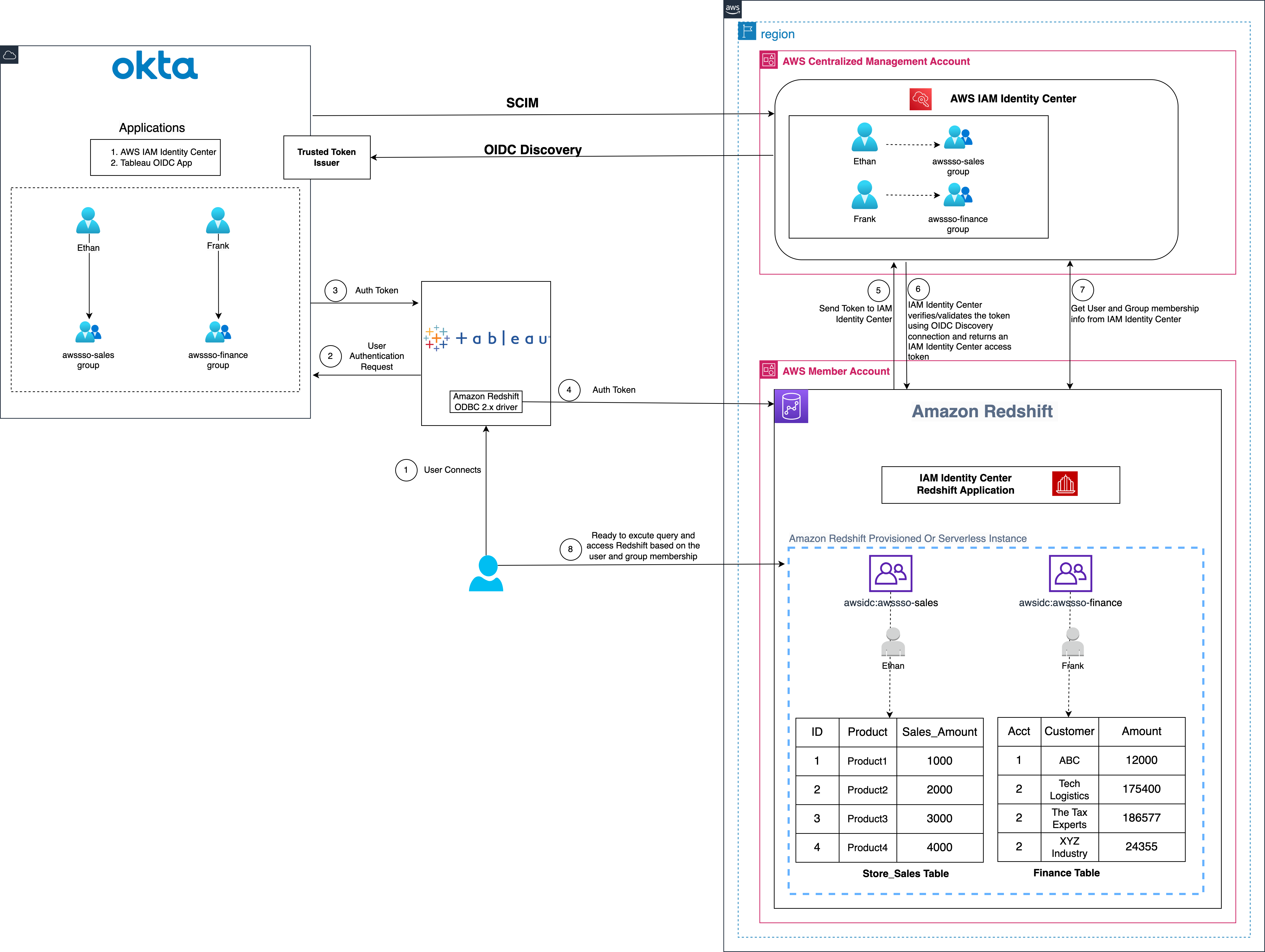
Sid Wray is a Senior Product Manager at Salesforce based in the Pacific Northwest with nearly 20 years of experience in Digital Advertising, Data Analytics, Connectivity Integration and Identity and Access Management. He currently focuses on supporting ISV partners for Salesforce Data Cloud.

Adiascar Cisneros is a Tableau Senior Product Manager based in Atlanta, GA. He focuses on the integration of the Tableau Platform with AWS services to amplify the value users get from our products and accelerate their journey to valuable, actionable insights. His background includes analytics, infrastructure, network security, and migrations.

Jade Koskela is a Principal Software Engineer at Salesforce. He has over a decade of experience building Tableau with a focus on areas including data connectivity, authentication, and identity federation.

Harshida Patel is a Principal Solutions Architect, Analytics with AWS.

Maneesh Sharma is a Senior Database Engineer at AWS with more than a decade of experience designing and implementing large-scale data warehouse and analytics solutions. He collaborates with various Amazon Redshift Partners and customers to drive better integration.

Ravi Bhattiprolu is a Senior Partner Solutions Architect at Amazon Web Services (AWS). He collaborates with strategic independent software vendor (ISV) partners like Salesforce and Tableau to design and deliver innovative, well-architected cloud products, integrations, and solutions to help joint AWS customers achieve their business goals.

How GitHub reduced testing time for iOS apps with new runner features

Post Syndicated from Stephen Glass original https://github.blog/engineering/infrastructure/how-github-reduced-testing-time-for-ios-apps-with-new-runner-features/


GitHub Actions 🤝 GitHub for iOS

The GitHub iOS and GitHub Actions macOS runner teams are integral parts of each other’s development inner loop. Each team partners on testing new runner images and hardware long before the features land in the hands of developers. GitHub Actions has been working hard at bringing the latest Mac hardware to the community. Apple silicon (M1) macOS runners are available for free in public repositories, along with larger options available for those jobs that need more performance.

The GitHub iOS team has been busy improving the user experience in the app, recently shipping such as GitHub Copilot Chat, code search, localization for German and Korean, and making it easier to work with issues and projects. In this blog, we will discuss how the GitHub iOS team brings the app to developers around the world, the benefits of Apple silicon, and building on GitHub Actions using macOS runners.

How GitHub reduced testing time for iOS apps with new runner features

The GitHub iOS team previously used a single workflow with one job to build and test the entire codebase on GitHub Actions that took 38 minutes to complete with the prior generation runners. The GitHub iOS app consists of about 60 first-party modules, consisting of various targets, such as dynamic frameworks, static libraries, app extensions, or the GitHub app itself. These modules range from networking layers to design system components to entire features or products, helping us maintain the app.

Breaking down the monolith

We decided to leverage the power of Apple silicon to speed up their testing process. We switched to M1 macOS runners (macos-14-xlarge YAML label) on GitHub Actions and split their test suite into separate jobs for each module. This way, they could build and test each module independently and get faster feedback. Some of the smallest modules completed their tests in as little as 2-3 minutes on M1 macOS runners, getting feedback to developers on their pull requests faster than ever before. This also made it easier to identify and fix failures on specific modules without waiting for a monolithic build to finish.

By using Apple silicon, we reduced their testing time by 60%, from 38 minutes to 15 minutes, and improved our productivity and efficiency. The figure below demonstrates how we broke down the monolith into small modules in order to improve our build times.

Image demonstrates the monolith build on tip with the total CI time. The Image below it demonstrates how per-module builds are crafted and the reduction in CI time with the new approach.

As each build is kicked off, GitHub Actions is behind the scenes preparing the required number of machines to execute the workflow. Each request is sent to the GitHub Actions service where it picks up a freshly reimaged virtual machine to execute the required number of jobs. The figure below shows how a request travels from our repository to the Actions Mac servers in Azure.

Image displays the relationship between the request for workflow to run and how a machine is assigned to a job. From left to right, the flow starts at GitHub.com, then the request is sent to Actions. Actions then finds the available macOS VM to execute the workflow.

With shorter build times and a scaling CI fleet, Apple silicon hosts allowed the GitHub iOS team to scale their jobs out across many shorter, faster steps, with GitHub Actions abstracting over the complexity of distributing CI jobs.

Analyzing CI performance

We further investigated the CI performance and divided each module’s CI into two separate steps, build and test, using xcodebuild’s build-without-testing and test-without-building. This helped us identify unit tests that ran for a long time or highlighted fast unit tests that finished in seconds.

Native development and test environments

With Apple silicon powering GitHub Actions runners and the developers’ laptops, our CI now had the same architecture as local development machines. Engineers could identify patterns that took a long time to compile or tests that failed due to the architecture from CI and fix them locally with confidence.

Benefits of Apple silicon

Apple silicon improves build performance, increases reliability, and lets iOS teams test natively for all Apple platforms throughout the software development lifecycle. They can avoid problems from cross-compilation or emulation and use the latest simulators on our GitHub Actions runner image. This ensures that their apps work well with the newest versions of iOS, iPadOS, watchOS, and tvOS. Our GitHub Actions M1 macOS runners help iOS teams leverage these benefits and deliver high-quality apps to their users faster and more efficiently. Additionally, GitHub Actions offers 50 concurrent runners for enterprise accounts and five for GitHub Free and Team plans. The GitHub for iOS team takes full advantage of these concurrent runners and initiates 50 jobs for every pull request to perform modular testing on the app in parallel.

Get started building on GitHub Actions using macOS runners

GitHub-hosted macOS runners are YAML-driven, meaning they are accessed by updating the runs on: key in your workflow file.

The post How GitHub reduced testing time for iOS apps with new runner features appeared first on The GitHub Blog.

[$] Debian’s /tmpest in a teapot

Post Syndicated from jzb original https://lwn.net/Articles/975565/

Debian had a major discussion
about mounting /tmp as a RAM-based tmpfs in 2012 but inertia
won out in the end. Debian systems have continued to
store temporary files on disk by default. Until now. A mere
12 years later, the project will be switching to a RAM-based /tmp in the Debian
13 (“Trixie”) release. Additionally, starting with Trixie, the
default will be to periodically clean up temporary files automatically in
/tmp and /var/tmp. Naturally, it involved a lengthy discussion first.

The collective thoughts of the interwebz