Tag Archives: Architecture

Field Notes: Building a Shared Account Structure Using AWS Organizations

Post Syndicated from Abhijit Vaidya original https://aws.amazon.com/blogs/architecture/field-notes-building-a-shared-account-structure-using-aws-organizations/

For customers considering the AWS Solution Provider Program, there are challenges to mitigate when building a shared account model with SI partners. AWS Organizations make it possible to build the right account structure to support a resale arrangement. In this engagement model, the end customer gets an AWS invoice from an AWS authorized partner instead of AWS directly.

Partners and customers who want to engage in this service resale arrangement need to build a new account structure. This process includes linking or transferring existing customer accounts to the partner master account. This is so that all the billing data from customer accounts is consolidated into the partner master account.

While linking or transferring existing customer accounts to the new master account, the partner must check the new master account structure. It should not compromise any customer security controls and continue to provide full control of linked accounts to the customer.  The new account structure must fulfill the following requirements for both the AWS customer and partner:

  • The customer maintains full access to the AWS organization and able to perform all critical security-related tasks except access to billing data.
  • The Partner is able to control only billing information and not able to perform any other task in the root account (master payer account) without approval from the customer.
  • In case of contract breach / termination, the customer is able to gain back full control of all accounts including the Master.

In this post, you will learn about how partners can create a master account with shared ownership. We also show how to link or transfer customer organization accounts to the new organization master account and set up policies that would provide appropriate access to both partner and customer.

Account Structure

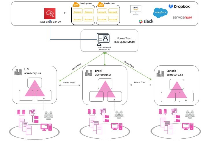
The following architecture represents the account structure setup that can fulfill customer and partner requirements as a part of a service resale arrangement.

As illustrated in the preceding diagram, the following list includes the key architectural components:

Architectural Components

As a part of resale arrangement, the customer’s existing AWS organization and related accounts are linked to the partner’s master payer account. The customer can continue to maintain their existing master root account, while all child accounts are linked to the master account (as shown in the list).

Customers may have valid concerns about linking/transferring accounts to the owned master payee account and may come up with many ‘what-if’ scenarios for example “What if the partner shuts down environment/servers?”  or, “What if partner blocks access to child accounts?”.

This account structure provides the right controls to both customer and partner that would address customer concerns around the security of their accounts. This includes the following benefits:

  • Starting with access to the root account, neither customer nor partner can access the root account without the other party’s involvement.
  • The partner controls the id/password for the root account while the customer maintains the MFA token for the account. The customer also controls the phone number, security questions associated with the root account. That way, the partner cannot replace the MFA token on their own.
  • The partner only has billing access and does not control any other parts of account including child accounts. Anytime the root account access is needed, both customer and partner team need to collaborate and access the root account.
  • The customer or partner cannot assign new IAM roles to themselves, therefore protecting the initial account setup.

Security considerations in the shared account setup

The following table highlights both customer and partner responsibilities and access controls provided by the architecture in the previous section.

The following points highlight security recommendations to provide adequate access rights to both partner and customers.

  • New master payer/ root account has a joint ownership between the Partner and the Customer.
  • AWS account root users (user id/password) would be with Partner and MFA (multi-factor authentication) device with Customer.
  • IAM (AWS Identity and Access Management) role to be created under the master payer with policies “FullOrganizationAccess”, “Amazon S3” (Amazon Simple Storage Service), “CloudTrail” (AWS CloudTrail), “CloudWatch”(Amazon CloudWatch) for the Customer.
  • Security team to log in and manage security of the account. Additional permissions to be added to this role as needed in future. This role does not have ANY billing permissions.
  • Only the partner has access to AWS billing and usage data.
  • IAM role / user would be created under master payer with just billing permission for the Partner team to log in and download all invoices. This role does not have any other permissions except billing and usage reports.
  • Any root login attempts to master payer triggers a notification to Customer’s SOC team and the Partner’s Customer account management team.
  • The Partner’ email address is used to create an account so invoices can be emailed to the partner’s email. The Customer cannot see these invoices.
  • The Customer phone number is used to create a master account and the customer maintains security questions/answers. This prevents replacement of MFA token by the Partner team without informing customer.  The Customer wouldn’t need the Partner’s help or permission to login and manage any security.
  • No aspect of  the Master Payer / Root Partner team can login to the master payer/Root without the Customer providing an MFA token.

Setting up the shared master AWS account structure

Create a playbook for the account transfer activity based on the following tasks. For each task, identify the owner. Make sure that owners have the right permissions to perform the tasks.

Part I – Setting up new partner master account

  1. Create new Partner Master payee Account
  2. Update payment details section with the required details for payment in Partner Master payee Account
  3. Enable MFA in the Partner Master payee Account
  4. Update contact for security and operations in the Partner Master payee Account
  5. Update demographics -Address and contact details in Partner Master payee Account
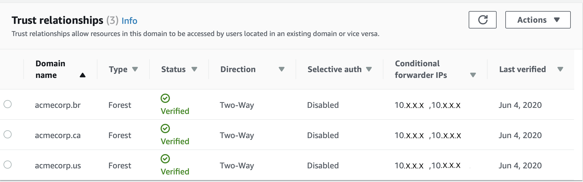
  6. Create an IAM role for Customer Team in Partner Master Payee account. IAM role is created under master payer with “FullOrganizationAccess”, “Amazon S3”, “CloudTrail”, “CloudWatch” “CloudFormationFullAccess” for the Customer SOC team to login and manage security of the account. Additional permissions can be added to this role in future if needed.

Select the roles:

create role

7. Create an IAM role/user for Partner billing role in the Partner Master Payee account.

Part II – Setting up customer master account

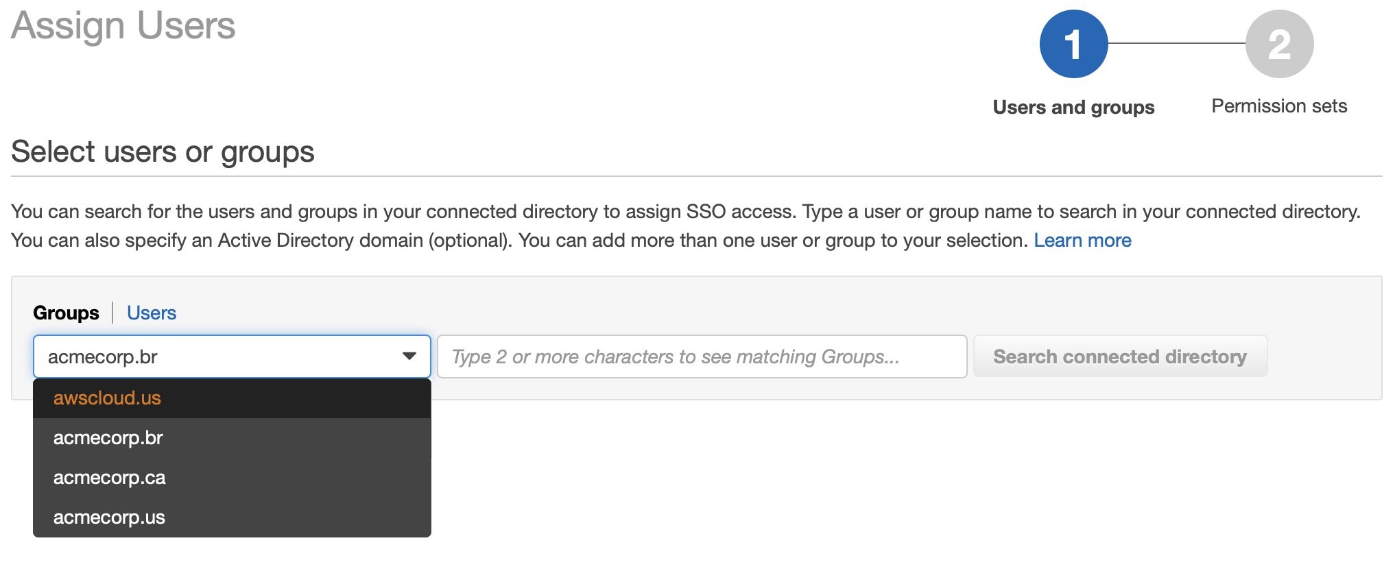
1.      Create an IAM user in the customer’s master account. This user assumes role into the new master payer/root account.

aws management console


2.      Confirm that when the IAM user from the customer account assumes a role in the new master account, and that the user does not have Billing Access.

Billing and cost management dashboard

Part III – Creating an organization structure in partner account

  1. Create an Organization in the Partner Master Payee Account
  2. Create Multiple Organizational Units (OU) in the Partner Master Payee Account


3. Enable Service Control Policies from AWS Organization’s Policies menu.

service control policies

5. Create/Copy Multiple in to Partner Master Payee Account from Customer root Account.  Any service control policies from the customer root account should be manually copied to new partner account.

6. If customer root account has any special software installed for example, security, install same software in Partner Master Payee Account.

7. Set alerts in Partner Master Payee root account. Any login to the root account would send alerts to customer and partner teams.

8. It is recommended to keep a copy of all billing history invoices for all accounts to be transferred to partner organization. This could be achieved by either downloading CSV or printing all invoices and storing files in Amazon S3 for long term archival. Billing history and invoices are found by clicking Orders and Invoices on Billing & Cost Management Dashboard. After accounts are transferred to new organization, historic billing data will not be available for those accounts.

9. Remove all the Member Accounts from the current Customer Root Account/ Organization. This step is performed by customer account admin and required before account can be transferred to Partner Account organization.

10. Send an invite from the Partner Master Payee Account to the delinked Member Account

master payee account

11.      Member Accounts to accept the invite from the Partner Master Payee Account.

invitations

12.      Move the Customer member account to the appropriate OU in the Partner Master Payee Account.

Setting the shared security model between partner and customer contact

While setting up the master account, three contacts need to be updated for notification.

  • Billing –  this is owned by the Partner
  • Operations – this is owned by the Customer
  • Security – this is owned by the Customer.

This will trigger a notification of any activity on the root account. The contact details contain Name, Title, Email Address and Phone number.  It is recommended to use the Customer’s SOC team distribution email for security and operations, and a phone number that belongs to the organization, and not the individual.

Alternate contacts

Additionally, before any root account activity takes place, AWS Support will verify using the security challenge questionnaire. These questions and answers are owned by the Customer’s SOC team.

security challenge questions

If a customer is not able to access the AWS account, alternate support options are available at Contact us by expanding the “I’m an AWS customer and I’m looking for billing or account support” menu. While contacting AWS Support, all the details that are listed on the account are needed, including full name, phone number, address, email address, and the last four digits of the credit card.

Clean Up

After recovering the account, the Customer should close any accounts that are not in use. It’s a good idea not to have open accounts in your name that could result in charges. For more information, review Closing an Account in the Billing and Cost Management User Guide.

The Shared master root account should be only used for selected activities referred to in the following document.

Conclusion

In this post, you learned how AWS Organizations features can be used to create a shared master account structure.  This helps both customer and partner engage in a service resale business engagement. Using AWS Organizations and cross account access, this solution allows customers to control all key aspects of managing the AWS Organization (Security / Logging / Monitoring) and also allows partners to control any billing related data.

Additional Resources

Cross Account Access

Field Notes provides hands-on technical guidance from AWS Solutions Architects, consultants, and technical account managers, based on their experiences in the field solving real-world business problems for customers.

Dream11: Scaling a Fantasy Sports Platform with 5M Daily Active Users

Post Syndicated from Annik Stahl original https://aws.amazon.com/blogs/architecture/scaling-fantasy-sports-platform/

Founded in 2008, Dream11 is India’s leading sports-tech startup with a growing base of more than 45 million users playing multiple sports such as fantasy cricket, football, kabaddi, and basketball.

Dream11 uses Amazon Aurora with Amazon ElastiCache to serve 1 million concurrent users within 50ms response time, serving at an average 3 million requests per minute (rpm), which can surge to 3X in a 30-second time span. In this video, we’ll be shedding some light on our architecture, along with our battle plan to handle transactions without locking. We’ll also talk about the features of Aurora and ElastiCache that helped Dream11 to handle 5 million daily active users with 4X growth YoY.

For more content like this, subscribe to our YouTube channels This is My Architecture, This is My Code, and This is My Model, or visit the This is My Architecture on AWS, which has search functionality and the ability to filter by industry, language, and service.

Field Notes: Integrating a Multi-forest Source Environment with AWS SSO

Post Syndicated from Sudhir Amin original https://aws.amazon.com/blogs/architecture/field-notes-integrating-a-multi-forest-source-environment-with-aws-sso/

During re:Invent 2019, AWS announced a new way to integrate external identity sources such as Azure Active Directory with auto provisioning of identities and groups in AWS Single Sign-On (AWS SSO). In March 2020, AWS SSO afforded customers the possibility to connect their Okta Identity Cloud to AWS Single Sign-On (SSO) in order to manage access to AWS centrally in AWS SSO.

AWS Single Sign-On service helps to centralize management access to multiple AWS accounts and some cases tying back to corporate identities. This provides ready access to business applications and services. With this feature, companies can leverage AWS Single Sign-On for allowing federated access to multiple AWS accounts and cloud applications.

In this blog post, I discuss the challenges faced by customers running multi-forest environments or multiple Azure tenant subscriptions with this feature.  I also provide a different approach to solving this challenge with a brief overview of each solution presented.

Large Enterprise companies often require their security team to build centralized identity solutions that work across different Active Directory forests environments. This is commonly due to a merger, acquisition or partnership. Challenges include complex networking with different IP routes, DNS forwarding configurations, firewall rules to enable trust relationships between different Active Directory forests to support compliance of a single identity to manage the account lifecycle and password policies. This becomes even more challenging when your organization is working in multiple cloud platforms within a centralized Identity solution, with hybrid networking connectivity.

Customer Example

To illustrate my point, I use the following example of a real life customer scenario, under the fictitious name of ‘Acme Corporation’.

Acme Corporation is a capital wealth management company operating in three countries: USA, Canada, and Brazil. Business is growing and they are exploring cloud services.

Their corporate headquarters is located in NY, USA and they have established offices (branches) in Canada and Brazil. The organization operates in a decentralized model, which consists of different governance over their identity structure. An Active Directory Forest is established per Region with a cross-forest trust relationship. The company is looking to adopt cloud technologies and needed a common identity solution across on-premises and cloud services with Azure Active Directory and AWS.

We’ve outlined the solution in the following diagram:

Figure 1 - Solution Overview

Figure 1 – Solution Overview

Options to source identities into AWS Single Sign-On

AWS Single Sign-On offers the following 3 options to establish as an identity source:

  • AWS SSO
  • Active Directory
  • External Identity Provider
Figure 2 - Identity Source Options

Figure 2 – Identity Source Options

The first option; “AWS SSO” is a default native identity store. You can create and delete users and groups.

The second option; “Active Directory” allows administrators to source users and groups from Active Directory running On-Premises Active Directory, or Active Directory in EC2 (using AD Connector as the directory gateway) or AWS Managed Microsoft AD directory hosted in the AWS Cloud.

The third option; “External Identity Provider” enables administrators to provision users and groups from external identity providers (IdPs) through the Security Assertion Markup Language (SAML) 2.0 standard.

Note: AWS Single Sign-On allows only one identity source at any given time. In this post, we focus on two options that help integrate a multi-forest environment with AWS Single Sign-On and Azure Active Directory.

Solution

Option 1. Federating with Active Directory 

In the hub-and-spoke model, the AWS Managed Microsoft Active Directory is the hub and the spoke is the Active Directory forests.

  1. Provision a AWS Managed Microsoft Active Directory.
    • If you already have an AWS Managed Microsoft Active Directory for a hub, continue to the next step.
  2. Setup hybrid network connectivity, and firewall rules allowing trust traffic
  3. DNS, conditional forwarding allows to resolve the trusting forests. We need an Outbound Endpoint with Forwarding Rules to the different forests so the VPC resolves the names and an inbound endpoint so the forests can resolve the AWS Managed Microsoft AD names.
  4. Check the name resolution is working for the hybrid environment.
  5. Establish a Forest trust relationship and validate the trust.

The following snapshot shows how your trust relationship will be displayed on the console.

Figure 3 - Trust Relationships

Note 1: You cannot use the transitive trust relationship of a child domain in a forest or cross forest relationship. In that case, you have to create an explicit trust or a domain trust to the AWS Managed Microsoft AD domain for AWS Single Sign-On. This enables you to see the user and groups required to provision the permission sets and Accounts.

Note 2: AWS Managed Microsoft Active Directory in this example does not require you to host any users or groups, as this domain is only being used for the domain trust relationships. In short, this can be an empty forest.

Configure AWS Single Sign-On to use your AWS Managed Microsoft Active Directory for Active Directory option.

The following snapshot shows how to assign a group to an account in preparation for AWS Singles Sign-On enablement.

Figure 4 - Selecting Users or Groups

The following snapshot shows how to assign a group to an account in preparation for AWS Singles Sign-On enablement and selecting a group.

Figure 5 - Assigning Users

The following is a conceptual diagram of Acme corporation, after successful integration.

Figure 4 - Conceptual Diagram

Figure 3 – Option 1 – Conceptual Diagram

Option 2a. Federating with Azure Active Directory Single Tenant

If you have multiple-forests and would like to use a single tenant, here are the steps:

  1. Setup a single Azure AD Connect in any forest, to consolidate users from different forests to a single Azure Tenant.
  2. Configure AWS Single Sign-On to use your Single Azure Active Directory Tenant for External Identity Provider option.

The following is a conceptual diagram of Acme corporation, after successful integration.

Figure 5 - Option 2a - Conceptual Diagram

Figure 5 – Option 2a – Conceptual Diagram

Option 2b. Federating with Azure Active Directory Multiple Tenants

If option 2a is not feasible and you are using multiple Azure AD Connect sync servers and multiple Azure Active Directory tenants (as per the following diagram) then, you can nominate one of the Azure Active Directory tenants to connect with AWS SSO. Through B2B invitation, selectively invite users from other tenants into the nominated tenant.

Note: This is not a scalable solution, as it requires administrative overhead. This should be ideal for a small set of users requiring access to AWS API or console for administrative work.

The following is a conceptual diagram of Acme corporation, after successful integration.

Figure 6 - Option 2b - Conceptual Diagram

Figure 6 – Option 2b – Conceptual Diagram

Conclusion

In this post, we discussed the options for connecting AWS SSO to your preferred Identity Provider, with a multi-forest infrastructure. Customers running multi-forest environments or multiple Azure tenant subscriptions now have a guide to offer their users a continued way of centralizing management and enforcing least privilege access on cloud resources. To learn more, review our AWS Single Sign-On service content.

Additional Content:

Field Notes provides hands-on technical guidance from AWS Solutions Architects, consultants, and technical account managers, based on their experiences in the field solving real-world business problems for customers.

Fundbox: Simplifying Ways to Query and Analyze Data by Different Personas

Post Syndicated from Annik Stahl original https://aws.amazon.com/blogs/architecture/fundbox-simplifying-ways-to-query-and-analyze-data-by-different-personas/

Fundbox is a leading technology platform focused on disrupting the $21 trillion B2B commerce market by building the world’s first B2B payment and credit network. With Fundbox, sellers of all sizes can quickly increase average order volumes (AOV) and improve close rates by offering more competitive net terms and payment plans to their SMB buyers. With heavy investments in machine learning and the ability to quickly analyze the transactional data of SMB’s, Fundbox is reimagining B2B payments and credit products in new category-defining ways.

Learn how how the company simplified the way different personas in the organization query and analyze data by building a self-service data orchestration platform. The platform architecture is entirely serverless, which simplifies the ability to scale and adopt to unpredictable demand. The platform was built using AWS Step Functions, AWS Lambda, Amazon API Gateway, Amazon DynamoDB, AWS Fargate, and other AWS Serverless managed services.

For more content like this, subscribe to our YouTube channels This is My Architecture, This is My Code, and This is My Model, or visit the This is My Architecture on AWS, which has search functionality and the ability to filter by industry, language, and service.

Field Notes: Serverless Container-based APIs with Amazon ECS and Amazon API Gateway

Post Syndicated from Simone Pomata original https://aws.amazon.com/blogs/architecture/field-notes-serverless-container-based-apis-with-amazon-ecs-and-amazon-api-gateway/

A growing number of organizations choose to build their APIs with Docker containers. For hosting and exposing these container-based APIs, they need a solution which supports HTTP requests routing, autoscaling, and high availability. In some cases, user authorization is also needed.

For this purpose, many organizations are orchestrating their containerized services with Amazon Elastic Container Service (Amazon ECS) or Amazon Elastic Kubernetes Service (Amazon EKS), while hosting their containers on Amazon EC2 or AWS Fargate. Then, they can add scalability and high availability with Service Auto Scaling (in Amazon ECS) or Horizontal Pod Auto Scaler (in Amazon EKS), and they expose the services through load balancers (for example, the AWS Application Load Balancer).

When you use Amazon ECS as an orchestrator (with EC2 or Fargate launch type), you also have the option to expose your services with Amazon API Gateway and AWS Cloud Map instead of a load balancer. AWS Cloud Map is used for service discovery: no matter how Amazon ECS tasks scale, AWS Cloud Map service names would point to the right set of Amazon ECS tasks. Then, API Gateway HTTP APIs can be used to define API routes and point them to the corresponding AWS Cloud Map services.

API Gateway and AWS Cloud Map could be a good fit if you want to leverage the capabilities provided by API Gateway HTTP APIs. For example, you could import/export your API as an OpenAPI definition file. You could configure the following features, either on the whole API or – more granularly – at route level: throttling, detailed metrics, or OAuth 2.0 / OIDC user authorization. You could also deploy your API at different stages over time. Or you could easily configure CORS for your API or for any route, instead of handling OPTIONS preflight requests yourself.

If you don’t need the capabilities of API Gateway HTTP APIs or if those of Elastic Load Balancing are a better fit, then you can use the latter. For example, the capabilities of the Application Load Balancer include: content-based routing (not only by path and HTTP method, but also by HTTP header, query-string parameter, source IP, etc.), redirects, fixed responses, and others. Additionally, the Network Load Balancer provides layer 4 load balancing capabilities. Ultimately, there are overlaps and differences between the features of Elastic Load Balancing and those of API Gateway HTTP APIs: so you may want to compare them to choose the right option for your use case.

This blog post guides you through the details of the option based on API Gateway and AWS Cloud Map, and how to implement it: first you learn how the different components (Amazon ECS, AWS Cloud Map, API Gateway, etc.) work together, then you launch and test a sample container-based API.

Architecture Overview

The following diagram shows the architecture of the sample API that you are going to launch.

Figure 1 - Architecture Diagram

Figure 1 – Architecture Diagram

This example API exposes two services: “Food store” to PUT and GET foods, and “Pet store” to PUT and GET pets. Unauthenticated users can only GET, while authenticated users can also PUT.

The following building blocks are used:

  1. Amazon Cognito User Pools: for user authentication. In this example API, Amazon Cognito is used for user authentication, but you could use any other OAuth 2.0 / OIDC identity provider instead. When the user authenticates with Amazon Cognito, user pool tokens are granted, including a JWT access token that is used for authorizing requests to the container APIs.
  2. API Gateway HTTP APIs: for exposing the containerized services to the user. API routes and the respective integrations are defined in API Gateway. A route is the combination of a path and a method. An integration is the backend service which is invoked by that route. In this API, private integrations point to AWS Cloud Map services, which in turn resolve to private Amazon ECS services (more about AWS Cloud Map in the next paragraph). As Amazon ECS services are private resources in a Virtual Private Cloud (VPC), API Gateway uses a VPC link to connect to them in a private way. A VPC link is a set of elastic network interfaces in the VPC, assigned to and managed by API Gateway, so that API Gateway can talk privately with other resources in the VPC. This way, Amazon ECS services can be launched in private subnets and don’t need a public IP. In this sample application, JWT authorization is configured in API Gateway for PUT routes. API Gateway performs requests authorization based on validation of the JWT Token provided, and optionally, scopes in the token. This way, you don’t need additional code in your containers for authorization.
  3. AWS Cloud Map: for service discovery of the containerized services. API Gateway needs a way to find physical addresses of the backend services, and AWS Cloud Map provides this capability. To enable this functionality, service discovery should be configured on Amazon ECS services. Amazon ECS performs periodic health checks on tasks in Amazon ECS services and registers the healthy tasks to the respective AWS Cloud Map service. AWS Cloud Map services can then be resolved either via DNS queries or by calling the DiscoverInstances API (API Gateway uses the API). AWS Cloud Map supports different DNS record types (including A, AAAA, CNAME, and SRV); at the time, of writing, API Gateway can only retrieve SRV records from AWS Cloud Map, so SRV records are used in this sample application. With SRV records, each AWS Cloud Map service returns a combination of IP addresses and port numbers of all the healthy tasks in the service. Consider that AWS Cloud Map would perform round-robin routing (with equal weighting to the targets): for this reason, to avoid hot spots, all tasks in each service should be homogeneous (in terms of container images, vCPU, memory, and other settings).
  4. Amazon ECS: for hosting the containerized services. Amazon ECS is a highly scalable and high-performance container orchestrator. In this blog post, the Fargate launch type is used, so that containers are launched on the Fargate serverless compute engine, and you don’t have to provision or manage any EC2 instances. In this sample API, service auto scaling is also enabled, so that the number of containers in each service can scale up and down automatically based on % CPU usage. Containers will be launched across multiple Availability Zones in the AWS Region, to get high availability.
  5. Amazon DynamoDB: for persisting the data. Amazon DynamoDB is a key-value and document database that provides single-millisecond performance at any scale. In a real-world scenario, you could still use DynamoDB or another data store, such as Amazon Relational Database Service (RDS).

All the code of this blog post is publicly available in this GitHub repository. You can explore the CloudFormation template used to define the sample application as code. You can view the source code of the two containerized services: Food store repository and Pet store repository. You can also explore the code of the sample web app that you’ll use to test the API (this web app has been developed with the Amplify framework). Note that the code provided is intended for testing purposes and not for production usage.

Walkthrough

In this section, you will deploy the sample application and test it.

Prerequisites

To launch the sample API, you first need an AWS user that has access to the AWS Management Console and has the IAM permissions to launch the AWS CloudFormation stack.

Deploying the sample application

Now it’s time to launch the sample API:

  1. Select Launch Stack
  2. In the page for quick stack creation, do the following:
    • Select the capability “I acknowledge that AWS CloudFormation might create IAM resources”.
    • Keep the rest as default.
    • Choose Create Stack.
  3. Wait until the status of the stack transitions to “CREATE_COMPLETE”.

Testing the sample application

In this section, you test the API from a sample web application client that I created. Open the sample web application:

  1. From the page of the stack, choose Outputs.
  2. Open the URL for the “APITestPage” output.
  3. On the opened page, choose Proceed.

The web page should state that you are not signed-in. In this sample API, any user can GET items, but only authenticated users can PUT items. Sign up to the sample web application:

  1. Choose Go To Sign In.
  2. Choose Create account.
  3. Complete the sign-up procedure (you will be asked for a valid email address, which will be registered into your Amazon Cognito User Pool).

The application should state that you are signed-in. Test the API as an authenticated user:

  1. Try to PUT an item. You would see that the operation succeeds. The item has been persisted by the containerized service to the DynamoDB table.

DynamoDB table


2.  Try to GET the same item that you previously PUT. You would see that the same JSON is returned. This JSON is retrieved by the containerized service from the DynamoDB table.

Test the API as an unauthenticated user:

  1. Choose Sign Out.
  2. Try to GET the same item that you previously PUT. You would see that the same JSON is returned. This JSON is retrieved by the containerized service from the DynamoDB table.
  3. Try to PUT any item. You would get a 401 Unauthorized error from the API. This behavior is expected because only signed-in users have a JWT token, and you configured API Gateway to only authorize PUT requests that provide a valid token.

DynamoDB table

Exploring the resources of the sample application

You can also explore the resources launched as part of the CloudFormation stack. To list all of them, from the page of your CloudFormation stack, choose Resources.

To see the Amazon ECS services, go to the Amazon ECS console, choose your cluster, and you would see that 2 services are running, one for the Foodstore and another for the Petstore, as shown in the following image.

Notice that the services use the Fargate launch type, meaning that they are running on serverless compute capacity, so you don’t have to launch or maintain any EC2 instances to run them.

Cluster demo

To see the details of a service, go to the Amazon ECS cluster page and choose a service. You land on the service page, where you can see the running tasks, the service events, and other details.

To view the service auto scaling configuration, choose Auto Scaling. You can notice that Amazon ECS is set to automatically scale the number of tasks according to the value of a metric. In this sample application, the metric is the average CPU utilization of the service (ECSServiceAverageCPUUtilization), but you could use another metric.

Auto scaling

The scaling policy of each service uses two Amazon CloudWatch Alarms, one for scaling out and one for scaling in. An alarm is triggered when the target metric deviates from the target value, which in turn is used to trigger the scaling action. To see the alarms, go to the CloudWatch Alarms console.

CloudWatch Alarms

To see the service discovery entries, go to the AWS Cloud Map console, choose your namespace (see the parameter “PrivateDNSNamespaceName” in the CloudFormation stack), and you would see that two services are defined. If you choose one of these services, you would see that multiple service instances are registered, each representing a single Amazon ECS task (in this sample application, each Amazon ECS task is a single container). If you choose one of these service instances, you would see the details about the task, including the private IP, the port, and the health status. API Gateway retrieves these entries to discover your services.

Service Instance

To see the API configuration, go to the API Gateway console and choose your API.

Then, from the left side of the screen select either Routes, Authorization, Integrations, or any other option.

Integrations

Cleaning up

To clean up the resources, simply delete the CloudFormation stack that you deployed as part of this blog post.

Conclusion

You have learned how API Gateway HTTP APIs can be used together with AWS Cloud Map to expose Amazon ECS services as APIs. You have deployed a sample API that also uses Amazon Cognito for authentication and DynamoDB for data persistence.

API Gateway HTTP APIs provides a number of features that you can leverage, such as OpenAPI import/export, throttling, OAuth 2.0 / OIDC user authorization, detailed metrics, and stages deployment. That said, API Gateway is not the only way to expose your ECS services; if you don’t need the features of API Gateway HTTP APIs or if those of Elastic Load Balancing are a better fit, then you can use the latter service. The recommended approach is to compare them to choose the most suitable for your use case.

Field Notes provides hands-on technical guidance from AWS Solutions Architects, consultants, and technical account managers, based on their experiences in the field solving real-world business problems for customers.

Open Sourcing Daytona: A Framework For Automated and Application-agnostic Performance Analysis

Post Syndicated from mikesefanov original https://yahooeng.tumblr.com/post/160987779296

By Sapan Panigrahi and Deepesh Mittal

Today, we are pleased to offer Daytona, an open-source framework for automated performance testing and analysis, to the community. Daytona is an application-agnostic framework to conduct integrated performance testing and analysis with repeatable test execution, standardized reporting, and built-in profiling support.

Daytona gives you the capability to build a customized test harness in a single, unified framework to test and analyze the performance of any application. You’ll get easy repeatability, consistent reporting, and the ability to capture trends. Daytona’s UI accepts a performance testing script that can run on a command line. This includes websites, databases, networks, or any workload you need to test and tune for performance. You can submit tests to the scheduler queue from the Daytona UI or from your CI/CD tool. You can deploy Daytona as a hosted service in your on-prem environment or on the public cloud of your choice. In fact, you can even host test harnesses for multiple applications with a single centralized service so that developers, architects, and systems engineers from different parts of your organization can work together on a unified view and manage your performance analysis on a continuous basis.

Daytona’s differentiation lies in its ability to aggregate and present essential aspects of application, system, and hardware performance metrics with a simple and unified user interface. This helps you maintain your focus on performance analysis without changing context across various sources and formats of data. The overall goal of performance analysis is to find ways of maximizing application throughput with minimum hardware resource and the best user experience. Metrics and insights from Daytona help achieve this objective.

Prior to Daytona, we created multiple, heterogenous performance tools to meet the specific needs of various applications. This meant that we often stored test results inconsistently, making it harder to analyze performance in a comprehensive manner. We had a difficult time sharing results and analyzing differences in test runs in a standard manner, which could lead to confusion.

With Daytona, we are now able to integrate all our load testing tools under a single framework and aggregate test results in one common central repository. We are gaining insight into the performance characteristics of many of our applications on a continuous basis. These insights help us optimize our applications which results in better utilization of our hardware resources and helps improve user experience by reducing the latency to serve end-user requests. Ultimately, Daytona helps us reduce capital expenditure on our large-scale infrastructure and makes our applications more robust under load. Sharing performance results in a common format encourages the use of common optimization techniques that we can leverage across many different applications.

Daytona was built knowing that we would want to publish it as open source and share the technology with the community for validation and improvement of the framework. We hope the community can help extend its use cases and make it suitable for an even broader set of applications and workloads.

Architecture

Daytona is comprised of a centralized scheduler, a distributed set of agents running on SUTs (systems under test), a MySQL database to store all metadata for tests, and a PHP-based UI. A test harness can be customized by answering a simple set of questions about the application/workload. A test can be submitted to Daytona’s queue through the UI or through a CLI (Command Line Interface) from the CI/CD system. The scheduler process polls the database for a test to be run and sends all the actions associated with the execution of the test to the agent running on a SUT. An agent process executes the test, collects application and system performance metrics, and sends the metrics back as a package to the scheduler. The scheduler saves the test metadata in the database and test results in the local file system. Tests from multiple harnesses proceed concurrently.

image

Architecture and Life Cycle Of A Test

Looking Forward

Our goal is to integrate Daytona with popular open source CI/CD tools and we welcome contributions from the community to make that happen. It is available under Apache License Version 2.0. To evaluate Daytona, we provide simple instructions to deploy it on your in-house bare metal, VM, or public cloud infrastructure. We also provide instructions so you can quickly have a test and development environment up and running on your laptop with Docker. Please join us on the path of making application performance analysis an enjoyable and insightful experience. Visit the Daytona Yahoo repo to get started!