All posts by Kevin Yung

Building Blue/Green application deployment to Micro Focus Enterprise Server

Post Syndicated from Kevin Yung original https://aws.amazon.com/blogs/devops/building-blue-green-application-deployment-to-micro-focus-enterprise-server/

Organizations running mainframe production workloads often follow the traditional approach of application deployment. To release new features of existing applications into production, the application is redeployed using the new version of software on the existing infrastructure. This poses the following challenges:

  • The cutover of the application deployment from testing to production usually takes place during a planned outage window with associated downtime.
  • Rollback is difficult, since the earlier version of the software must be redeployed from scratch on the existing infrastructure. This may result in applications being unavailable for longer durations owing to the rollback.
  • Due to differences in testing and production environments, some defects may leak into production, affecting the application code quality and thus increasing the number of production outages

Automated, robust application deployment is recognized as a prime driver for moving from a Mainframe to AWS, as service stability, security, and quality can be better managed. In this post, you will learn how to build Blue/Green (zero-downtime) deployments for mainframe applications rehosted to Micro Focus Enterprise Server with AWS Developer Tools (AWS CodeBuild, CodePipeline, and CodeDeploy).

This is a continuation of our previous post “Automate thousands of mainframe tests on AWS with the Micro Focus Enterprise Suite”. In our last post, we explained how you can implement a pattern for continuous integration and testing of mainframe applications with AWS Developer tools and Micro Focus Enterprise Suite. If you haven’t already checked it out, then we strongly recommend that you read through it before proceeding to the rest of this post.

Overview of solution

In this section, we explain the three important design “ingredients” to be implemented in the overall solution:

  1. Implementation of Enterprise Server Performance and Availability Cluster (PAC)
  2. End-to-end design of CI/CD pipeline for multiple teams development
  3. Blue/green deployment process for a rehosted mainframe application

First, let’s look at the solution design for the Micro Focus Enterprise Server PAC cluster.

Overview of Micro Focus Enterprise Server Performance and Availability Cluster (PAC)

In the Blue/Green deployment solution, Micro Focus Enterprise Server is the hosting environment for mainframe applications with the software installed into Amazon EC2 instances. Application deployment in Amazon EC2 Auto Scaling is one of the critical requirements to build a Blue/Green deployment. Micro Focus Enterprise Server PAC technology is the feature that allows for the Auto Scaling of Enterprise Server instances. For details on how to build Micro Focus Enterprise PAC Cluster with Amazon EC2 Auto Scaling and Systems Manager, see our AWS Prescriptive Guidance document. An overview of the infrastructure architecture is shown in the following figure, and the following table explains the components in the architecture.

Infrastructure architecture overview for blue/green application deployment to Micro Focus Enterprise Server

Components Description
Micro Focus Enterprise Servers Deploy applications to Micro Focus Enterprise Servers PAC in Amazon EC2 Auto Scaling Group.
Micro Focus Enterprise Server Common Web Administration (ESCWA) Manage Micro Focus Enterprise Server PAC with ESCWA server, e.g., Adding or Removing Enterprise Server to/from a PAC.
Relational Database for both user and system data files Setup Amazon Aurora RDS Instance in Multi-AZ to host both user and system data files to be shared across the Enterprise server instances.
Micro Focus Enterprise Server Scale-Out Repository (SOR) Setup an Amazon ElastiCache Redis Instance and replicas in Multi-AZ to host user data.
Application endpoint and load balancer Setup a Network Load Balancer to provide a hostname for end users to connect the application, e.g., accessing the application through a 3270 emulator.

CI/CD Pipelines design supporting multi-streams of mainframe development

In a previous DevOps post, Automate thousands of mainframe tests on AWS with the Micro Focus Enterprise Suite, we introduced two levels of pipelines. The first level of pipeline is used by mainframe project teams to test project scope changes. The second level of the pipeline is used for system integration tests, where the pipeline will perform tests for all of the promoted changes from the project pipelines and perform extensive systems tests.

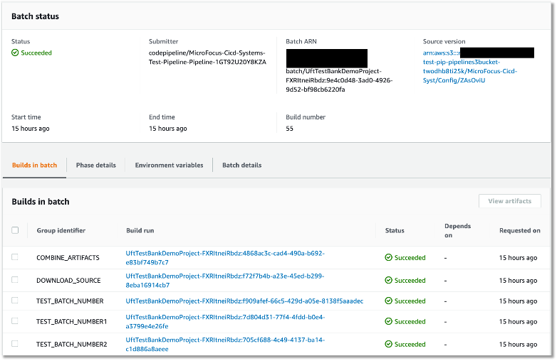
In this post, we are extending the two levels pipeline to add a production deployment pipeline. When system testing is complete and successful, the tested application artefacts are promoted to the production pipeline in preparation for live production release. The following figure depicts each stage of the three levels of CI/CD pipeline and the purpose of each stage.

Different levels of CI/CD pipeline - Project Team Pipeline, Systems Test Pipeline and Production Deployment Pipeline

Let’s look at the artifact promotion to production pipeline in greater detail. The Systems Test Pipeline promotes the tested artifacts in binary format into an Amazon S3 bucket and the S3 event triggers production pipeline to kick-off. This artifact promotion process can be gated using a manual approval action in CodePipeline. For customers who want to have a fully automated continuous deployment, the manual promotion approval step can be removed.

The following diagram shows the AWS Stages in AWS CodePipeline of the production deployment pipeline:

Stages in production deployment pipeline using AWS CodePipeline

After the production pipeline is kicked off, it downloads the new version artifact from the S3 bucket. See the details of how to setup the S3 bucket as a Source of CodePipeline in the document AWS CodePipeline Document S3 as Source

In the following section, we explain each of these pipeline stages in detail:

  1. It prepares and packages a new version of production configuration artifacts, for example, the Micro Focus Enterprise Server config file, blue/green deployment scripts etc.
  2. Use in the CodeBuild Project to kick off an application blue/green deployment with AWS CodeDeploy.
  3. Use a manual approval gate to wait for an operator to validate the new version of the application and approve to continue the production traffic switch
  4. Continue the blue/green deployment by allowing traffic to the new version of the application and block the traffic to the old version.
  5. After a successful Blue/Green switch and deployment, tag the production version in the code repository.

Now that you’ve seen the pipeline design, we will dive deep into the details of the blue/green deployment with AWS CodeDeploy.

Blue/green deployment with AWS CodeDeploy

In the blue/green deployment, we used the technique of swapping Auto Scaling Group behind an Elastic Load Balancer. Refer to the AWS Blue/Green deployment whitepaper for the details of the technique. As AWS CodeDeploy is a fully-managed service that automates software deployment, it is used to automate the entire Blue/Green process.

Firstly, the following best practices are applied to setup the Enterprise Server’s infrastructure:

  1. AWS Image Builder is used to install Micro Focus Enterprise Server software and AWS CodeDeploy Agent into Amazon Machine Image (AMI). Create an EC2 Launch Template with the Enterprise Server AMI ID.
  2. A Network Load Balancer is used to setup a TCP connection health check to validate that Micro Focus Enterprise Server is listening on the required ports, e.g., port 9270, so that connectivity is available for 3270 emulators.
  3. A script was created to confirm application deployment validity in each EC2 instance. This is achieved by using a PowerShell script that triggers a CICS transaction from the Micro Focus Enterprise Server command line interface.

In the CodePipeline, we created a CodeBuild project to create a new deployment with CodeDeploy. We will go into the details of the CodeBuild buildspec.yaml configuration.

In the CodeBuild buildspec.yaml’s pre_build section, we used the following steps:

In the pre-build stage, the CodeBuild will perform two steps:

  1. Create an initial Amazon EC2 Auto Scaling using Micro Focus Enterprise Server AMI and a Launch Template for the first-time deployment of the application.
  2. Use AWS CLI to update the initial Auto Scaling Group name into a Systems Manager Parameter Store, and it will later be used by CodeDeploy to create a copy during the blue/green deployment.

In the build stage, the buildspec will perform the following steps:

  1. Retrieve the Auto Scaling Group name of the Enterprise Servers from the Systems Manager Parameter Store.
  2. Then, a blue/green deployment configuration is created for the deployment group of the application. In the AWS CLI command, we use the WITH_TRAFFIC_CONTROL option to let us manually verify and approve before switching the traffic to the new version of the application. The command snippet is shown here.
BlueGreenConf=\
        "terminateBlueInstancesOnDeploymentSuccess={action=TERMINATE}"\
        ",deploymentReadyOption={actionOnTimeout=STOP_DEPLOYMENT,waitTimeInMinutes=600}" \
        ",greenFleetProvisioningOption={action=COPY_AUTO_SCALING_GROUP}"

DeployType="BLUE_GREEN,deploymentOption=WITH_TRAFFIC_CONTROL"

/usr/local/bin/aws deploy update-deployment-group \
      --application-name "${APPLICATION_NAME}" \
     --current-deployment-group-name "${DEPLOYMENT_GROUP_NAME}" \
     --auto-scaling-groups "${AsgName}" \
      --load-balancer-info targetGroupInfoList=[{name="${TARGET_GROUP_NAME}"}] \
      --deployment-style "deploymentType=$DeployType" \
      --Blue/Green-deployment-configuration "$BlueGreenConf"
  1. Next, the new version of application binary is released from the CodeBuild source DemoBinto the production S3 bucket.
release="bankdemo-$(date '+%Y-%m-%d-%H-%M').tar.gz"
RELEASE_FILE="s3://${PRODUCTION_BUCKET}/${release}"

/usr/local/bin/aws deploy push \
    --application-name ${APPLICATION_NAME} \
    --description "version - $(date '+%Y-%m-%d %H:%M')" \
    --s3-location ${RELEASE_FILE} \
    --source ${CODEBUILD_SRC_DIR_DemoBin}/
  1. Create a new deployment for the application to initiate the Blue/Green switch.
/usr/local/bin/aws deploy create-deployment \
    --application-name ${APPLICATION_NAME} \
    --s3-location bucket=${PRODUCTION_BUCKET},key=${release},bundleType=zip \
    --deployment-group-name "${DEPLOYMENT_GROUP_NAME}" \
    --description "Bankdemo Production Deployment ${release}"\
    --query deploymentId \
    --output text

After setting up the deployment options, the following is a snapshot of a deployment configuration from the AWS Management Console.

Snapshot of deployment configuration from AWS Management Console

In the AWS Post “Under the Hood: AWS CodeDeploy and Auto Scaling Integration”, we explain how AWS CodeDeploy sets up Auto Scaling lifecycle hooks to listen for Auto Scaling events. In the event of an EC2 instance launch and termination, AWS CodeDeploy can instruct its agent in the instance to run the prepared scripts.

In the following table, we list each stage in a blue/green deployment and the tasks that ran.

Hooks Tasks
BeforeInstall Create application folder structures in the newly launched Amazon EC2 and prepare for installation
  AfterInstall Enable Windows Firewall Rule for application traffic
Activate Micro Focus License using License Server
Prepare Production Database Connections
Import config to create Region in Micro Focus Enterprise Server
Deploy the latest application binaries into each of the Micro Focus Enterprise Servers
ApplicationStart Use AWS CLI to start a Systems Manager Automation “Scale-Out” runbook with the target of ESCWA server
The Automation runbook will add the newly launched Micro Focus Enterprise Server instance into a PAC
The Automation runbook will start the imported region in the newly launched Micro Focus Enterprise Server
Validate that the application is listening on a service port, for example, port 9270
Use the Micro Focus command “castran” to run an online transaction in Micro Focus Enterprise Server to validate the service status
AfterBlockTraffic Use AWS CLI to start a Systems Manager Automation “Scale-In” runbook with the target ESCWA server
The Automation runbook will try stopping the Region in the terminating EC2 instance
The Automation runbook will remove the Enterprise Server instance from the PAC

The tasks in the table are automated using PowerShell, and the scripts are used in appspec.yml config for CodeDeploy to orchestrate the deployment.

In the following appspec.yml, the locations of the binary files to be installed are defined in addition to the Micro Focus Enterprise Server Region XML config file. During the AfrerInstall stage, the XML config is imported into the Enterprise Server.

version: 0.0
os: windows
files:
  - source: scripts
    destination: C:\scripts\
  - source: online
    destination: C:\BANKDEMO\online\
  - source: common
    destination: C:\BANKDEMO\common\
  - source: batch
    destination: C:\BANKDEMO\batch\
  - source: scripts\BANKDEMO.xml
    destination: C:\BANKDEMO\
hooks:
  BeforeInstall: 
    - location: scripts\BeforeInstall.ps1
      timeout: 300
  AfterInstall: 
    - location: scripts\AfterInstall.ps1    
  ApplicationStart:
    - location: scripts\ApplicationStart.ps1
      timeout: 300
  ValidateService:
    - location: scripts\ValidateServer.cmd
      timeout: 300
  AfterBlockTraffic:
    - location: scripts\AfterBlockTraffic.ps1

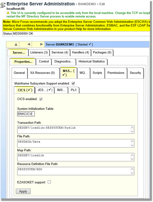
Using the sample Micro Focus Bankdemo application, and the steps outlined above, we have setup a blue/green deployment process in Micro Focus Enterprise Server.

There are four important considerations when setting up blue/green deployment:

  1. For batch applications, the blue/green deployment should be invoked only outside of the scheduled “batch window”.
  2. For online applications, AWS CodeDeploy will deregister the Auto Scaling group from the target group of the Network Load Balancer. The deregistration may take a while as the server has to finish processing the ongoing requests before it can continue deployment of the new application instance. In this case, enabling Elastic Load Balancing connection draining feature with appropriate timeout value can minimize the risk of closing unfinished transactions. In addition, consider doing deployment in low-traffic windows to improve the deployment speeds.
  3. For application changes that require updates to the database schema, the version roll-forward and rollback can be managed via DB migrations tools, e.g., Flyway and Fluent Migrator.
  4. For testing in production environments, adherence to any regulatory compliance, such as full audit trail of events, must be considered.

Conclusion

In this post, we introduced the solution to use Micro Focus Enterprise Server PAC, Amazon EC2 Auto Scaling, AWS Systems Manager, and AWS CodeDeploy to automate the blue/green deployment of rehosted mainframe applications in AWS.

Through the blue/green deployment methodology, we can shift traffic between two identical clusters running different application versions in parallel. This mitigates the risks commonly associated with mainframe application deployment, namely downtime and rollback capacity, while ensure higher code quality in production through “Shift Right” testing.

A demo of the solution is available on the AWS Partner Micro Focus website [Solution-Demo]. If you’re interested in modernizing your mainframe applications, then please contact Micro Focus and AWS mainframe business development at [email protected].

Additional Information

About the authors

Kevin Yung

Kevin Yung

Kevin is a Senior Modernization Architect in AWS Professional Services Global Mainframe and Midrange Modernization (GM3) team. Kevin currently is focusing on leading and delivering mainframe and midrange applications modernization for large enterprise customers.

Krithika Palani Selvam

Krithika is a Senior Modernization Architect in AWS Professional Services Global Mainframe and Midrange Modernization (GM3) team. She is currently working with enterprise customers for migrating and modernizing mainframe and midrange applications to cloud.

Peter Woods

Peter Woods has been with Micro Focus for over 30 years <within the Application Modernisation & Connectivity portfolio>. His diverse range of roles has included Technical Support, Channel Sales, Product Management, Strategic Alliances Management and Pre-Sales and was primarily based in the UK. In 2017 Peter re-located to Melbourne, Australia and in his current role of AM2C APJ Regional Technical Leader and ANZ Pre-Sales Manager, he is charged with driving and supporting Application Modernisation sales activity across the APJ region.

Abraham Mercado Rondon

Abraham Rondon is a Solutions Architect working on Micro Focus Enterprise Solutions for the Application Modernization team based in Melbourne. After completing a degree in Statistics and before joining Micro Focus, Abraham had a long career in supporting Mainframe Applications in different countries doing progressive roles from Developer to Production Support, Business and Technical Analyst, and Project Team Lead.  Now, a vital part of the Micro Focus Application Modernization team, one of his main focus is Cloud implementations of mainframe DevOps and production workload rehost.

Automate thousands of mainframe tests on AWS with the Micro Focus Enterprise Suite

Post Syndicated from Kevin Yung original https://aws.amazon.com/blogs/devops/automate-mainframe-tests-on-aws-with-micro-focus/

Micro Focus – AWS Advanced Technology Parnter, they are a global infrastructure software company with 40 years of experience in delivering and supporting enterprise software.

We have seen mainframe customers often encounter scalability constraints, and they can’t support their development and test workforce to the scale required to support business requirements. These constraints can lead to delays, reduce product or feature releases, and make them unable to respond to market requirements. Furthermore, limits in capacity and scale often affect the quality of changes deployed, and are linked to unplanned or unexpected downtime in products or services.

The conventional approach to address these constraints is to scale up, meaning to increase MIPS/MSU capacity of the mainframe hardware available for development and testing. The cost of this approach, however, is excessively high, and to ensure time to market, you may reject this approach at the expense of quality and functionality. If you’re wrestling with these challenges, this post is written specifically for you.

To accompany this post, we developed an AWS prescriptive guidance (APG) pattern for developer instances and CI/CD pipelines: Mainframe Modernization: DevOps on AWS with Micro Focus.

Overview of solution

In the APG, we introduce DevOps automation and AWS CI/CD architecture to support mainframe application development. Our solution enables you to embrace both Test Driven Development (TDD) and Behavior Driven Development (BDD). Mainframe developers and testers can automate the tests in CI/CD pipelines so they’re repeatable and scalable. To speed up automated mainframe application tests, the solution uses team pipelines to run functional and integration tests frequently, and uses systems test pipelines to run comprehensive regression tests on demand. For more information about the pipelines, see Mainframe Modernization: DevOps on AWS with Micro Focus.

In this post, we focus on how to automate and scale mainframe application tests in AWS. We show you how to use AWS services and Micro Focus products to automate mainframe application tests with best practices. The solution can scale your mainframe application CI/CD pipeline to run thousands of tests in AWS within minutes, and you only pay a fraction of your current on-premises cost.

The following diagram illustrates the solution architecture.

Mainframe DevOps On AWS Architecture Overview, on the left is the conventional mainframe development environment, on the left is the CI/CD pipelines for mainframe tests in AWS

Figure: Mainframe DevOps On AWS Architecture Overview


Best practices

Before we get into the details of the solution, let’s recap the following mainframe application testing best practices:

  • Create a “test first” culture by writing tests for mainframe application code changes
  • Automate preparing and running tests in the CI/CD pipelines
  • Provide fast and quality feedback to project management throughout the SDLC
  • Assess and increase test coverage
  • Scale your test’s capacity and speed in line with your project schedule and requirements

Automated smoke test

In this architecture, mainframe developers can automate running functional smoke tests for new changes. This testing phase typically “smokes out” regression of core and critical business functions. You can achieve these tests using tools such as py3270 with x3270 or Robot Framework Mainframe 3270 Library.

The following code shows a feature test written in Behave and test step using py3270:

# home_loan_calculator.feature
Feature: calculate home loan monthly repayment
  the bankdemo application provides a monthly home loan repayment caculator 
  User need to input into transaction of home loan amount, interest rate and how many years of the loan maturity.
  User will be provided an output of home loan monthly repayment amount

  Scenario Outline: As a customer I want to calculate my monthly home loan repayment via a transaction
      Given home loan amount is <amount>, interest rate is <interest rate> and maturity date is <maturity date in months> months 
       When the transaction is submitted to the home loan calculator
       Then it shall show the monthly repayment of <monthly repayment>

    Examples: Homeloan
      | amount  | interest rate | maturity date in months | monthly repayment |
      | 1000000 | 3.29          | 300                     | $4894.31          |


# home_loan_calculator_steps.py
import sys, os
from py3270 import Emulator
from behave import *

@given("home loan amount is {amount}, interest rate is {rate} and maturity date is {maturity_date} months")
def step_impl(context, amount, rate, maturity_date):
    context.home_loan_amount = amount
    context.interest_rate = rate
    context.maturity_date_in_months = maturity_date

@when("the transaction is submitted to the home loan calculator")
def step_impl(context):
    # Setup connection parameters
    tn3270_host = os.getenv('TN3270_HOST')
    tn3270_port = os.getenv('TN3270_PORT')
	# Setup TN3270 connection
    em = Emulator(visible=False, timeout=120)
    em.connect(tn3270_host + ':' + tn3270_port)
    em.wait_for_field()
	# Screen login
    em.fill_field(10, 44, 'b0001', 5)
    em.send_enter()
	# Input screen fields for home loan calculator
    em.wait_for_field()
    em.fill_field(8, 46, context.home_loan_amount, 7)
    em.fill_field(10, 46, context.interest_rate, 7)
    em.fill_field(12, 46, context.maturity_date_in_months, 7)
    em.send_enter()
    em.wait_for_field()    

    # collect monthly replayment output from screen
    context.monthly_repayment = em.string_get(14, 46, 9)
    em.terminate()

@then("it shall show the monthly repayment of {amount}")
def step_impl(context, amount):
    print("expected amount is " + amount.strip() + ", and the result from screen is " + context.monthly_repayment.strip())
assert amount.strip() == context.monthly_repayment.strip()

To run this functional test in Micro Focus Enterprise Test Server (ETS), we use AWS CodeBuild.

We first need to build an Enterprise Test Server Docker image and push it to an Amazon Elastic Container Registry (Amazon ECR) registry. For instructions, see Using Enterprise Test Server with Docker.

Next, we create a CodeBuild project and uses the Enterprise Test Server Docker image in its configuration.

The following is an example AWS CloudFormation code snippet of a CodeBuild project that uses Windows Container and Enterprise Test Server:

  BddTestBankDemoStage:
    Type: AWS::CodeBuild::Project
    Properties:
      Name: !Sub '${AWS::StackName}BddTestBankDemo'
      LogsConfig:
        CloudWatchLogs:
          Status: ENABLED
      Artifacts:
        Type: CODEPIPELINE
        EncryptionDisabled: true
      Environment:
        ComputeType: BUILD_GENERAL1_LARGE
        Image: !Sub "${EnterpriseTestServerDockerImage}:latest"
        ImagePullCredentialsType: SERVICE_ROLE
        Type: WINDOWS_SERVER_2019_CONTAINER
      ServiceRole: !Ref CodeBuildRole
      Source:
        Type: CODEPIPELINE
        BuildSpec: bdd-test-bankdemo-buildspec.yaml

In the CodeBuild project, we need to create a buildspec to orchestrate the commands for preparing the Micro Focus Enterprise Test Server CICS environment and issue the test command. In the buildspec, we define the location for CodeBuild to look for test reports and upload them into the CodeBuild report group. The following buildspec code uses custom scripts DeployES.ps1 and StartAndWait.ps1 to start your CICS region, and runs Python Behave BDD tests:

version: 0.2
phases:
  build:
    commands:
      - |
        # Run Command to start Enterprise Test Server
        CD C:\
        .\DeployES.ps1
        .\StartAndWait.ps1

        py -m pip install behave

        Write-Host "waiting for server to be ready ..."
        do {
          Write-Host "..."
          sleep 3  
        } until(Test-NetConnection 127.0.0.1 -Port 9270 | ? { $_.TcpTestSucceeded } )

        CD C:\tests\features
        MD C:\tests\reports
        $Env:Path += ";c:\wc3270"

        $address=(Get-NetIPAddress -AddressFamily Ipv4 | where { $_.IPAddress -Match "172\.*" })
        $Env:TN3270_HOST = $address.IPAddress
        $Env:TN3270_PORT = "9270"
        
        behave.exe --color --junit --junit-directory C:\tests\reports
reports:
  bankdemo-bdd-test-report:
    files: 
      - '**/*'
    base-directory: "C:\\tests\\reports"

In the smoke test, the team may run both unit tests and functional tests. Ideally, these tests are better to run in parallel to speed up the pipeline. In AWS CodePipeline, we can set up a stage to run multiple steps in parallel. In our example, the pipeline runs both BDD tests and Robot Framework (RPA) tests.

The following CloudFormation code snippet runs two different tests. You use the same RunOrder value to indicate the actions run in parallel.

#...
        - Name: Tests
          Actions:
            - Name: RunBDDTest
              ActionTypeId:
                Category: Build
                Owner: AWS
                Provider: CodeBuild
                Version: 1
              Configuration:
                ProjectName: !Ref BddTestBankDemoStage
                PrimarySource: Config
              InputArtifacts:
                - Name: DemoBin
                - Name: Config
              RunOrder: 1
            - Name: RunRbTest
              ActionTypeId:
                Category: Build
                Owner: AWS
                Provider: CodeBuild
                Version: 1
              Configuration:
                ProjectName : !Ref RpaTestBankDemoStage
                PrimarySource: Config
              InputArtifacts:
                - Name: DemoBin
                - Name: Config
              RunOrder: 1  
#...

The following screenshot shows the example actions on the CodePipeline console that use the preceding code.

Screenshot of CodePipeine parallel execution tests using a same run order value

Figure – Screenshot of CodePipeine parallel execution tests

Both DBB and RPA tests produce jUnit format reports, which CodeBuild can ingest and show on the CodeBuild console. This is a great way for project management and business users to track the quality trend of an application. The following screenshot shows the CodeBuild report generated from the BDD tests.

CodeBuild report generated from the BDD tests showing 100% pass rate

Figure – CodeBuild report generated from the BDD tests

Automated regression tests

After you test the changes in the project team pipeline, you can automatically promote them to another stream with other team members’ changes for further testing. The scope of this testing stream is significantly more comprehensive, with a greater number and wider range of tests and higher volume of test data. The changes promoted to this stream by each team member are tested in this environment at the end of each day throughout the life of the project. This provides a high-quality delivery to production, with new code and changes to existing code tested together with hundreds or thousands of tests.

In enterprise architecture, it’s commonplace to see an application client consuming web services APIs exposed from a mainframe CICS application. One approach to do regression tests for mainframe applications is to use Micro Focus Verastream Host Integrator (VHI) to record and capture 3270 data stream processing and encapsulate these 3270 data streams as business functions, which in turn are packaged as web services. When these web services are available, they can be consumed by a test automation product, which in our environment is Micro Focus UFT One. This uses the Verastream server as the orchestration engine that translates the web service requests into 3270 data streams that integrate with the mainframe CICS application. The application is deployed in Micro Focus Enterprise Test Server.

The following diagram shows the end-to-end testing components.

Regression Test the end-to-end testing components using ECS Container for Exterprise Test Server, Verastream Host Integrator and UFT One Container, all integration points are using Elastic Network Load Balancer

Figure – Regression Test Infrastructure end-to-end Setup

To ensure we have the coverage required for large mainframe applications, we sometimes need to run thousands of tests against very large production volumes of test data. We want the tests to run faster and complete as soon as possible so we reduce AWS costs—we only pay for the infrastructure when consuming resources for the life of the test environment when provisioning and running tests.

Therefore, the design of the test environment needs to scale out. The batch feature in CodeBuild allows you to run tests in batches and in parallel rather than serially. Furthermore, our solution needs to minimize interference between batches, a failure in one batch doesn’t affect another running in parallel. The following diagram depicts the high-level design, with each batch build running in its own independent infrastructure. Each infrastructure is launched as part of test preparation, and then torn down in the post-test phase.

Regression Tests in CodeBuoild Project setup to use batch mode, three batches running in independent infrastructure with containers

Figure – Regression Tests in CodeBuoild Project setup to use batch mode

Building and deploying regression test components

Following the design of the parallel regression test environment, let’s look at how we build each component and how they are deployed. The followings steps to build our regression tests use a working backward approach, starting from deployment in the Enterprise Test Server:

  1. Create a batch build in CodeBuild.
  2. Deploy to Enterprise Test Server.
  3. Deploy the VHI model.
  4. Deploy UFT One Tests.
  5. Integrate UFT One into CodeBuild and CodePipeline and test the application.

Creating a batch build in CodeBuild

We update two components to enable a batch build. First, in the CodePipeline CloudFormation resource, we set BatchEnabled to be true for the test stage. The UFT One test preparation stage uses the CloudFormation template to create the test infrastructure. The following code is an example of the AWS CloudFormation snippet with batch build enabled:

#...
        - Name: SystemsTest
          Actions:
            - Name: Uft-Tests
              ActionTypeId:
                Category: Build
                Owner: AWS
                Provider: CodeBuild
                Version: 1
              Configuration:
                ProjectName : !Ref UftTestBankDemoProject
                PrimarySource: Config
                BatchEnabled: true
                CombineArtifacts: true
              InputArtifacts:
                - Name: Config
                - Name: DemoSrc
              OutputArtifacts:
                - Name: TestReport                
              RunOrder: 1
#...

Second, in the buildspec configuration of the test stage, we provide a build matrix setting. We use the custom environment variable TEST_BATCH_NUMBER to indicate which set of tests runs in each batch. See the following code:

version: 0.2
batch:
  fast-fail: true
  build-matrix:
    static:
      ignore-failure: false
    dynamic:
      env:
        variables:
          TEST_BATCH_NUMBER:
            - 1
            - 2
            - 3 
phases:
  pre_build:
commands:
#...

After setting up the batch build, CodeBuild creates multiple batches when the build starts. The following screenshot shows the batches on the CodeBuild console.

Regression tests Codebuild project ran in batch mode, three batches ran in prallel successfully

Figure – Regression tests Codebuild project ran in batch mode

Deploying to Enterprise Test Server

ETS is the transaction engine that processes all the online (and batch) requests that are initiated through external clients, such as 3270 terminals, web services, and websphere MQ. This engine provides support for various mainframe subsystems, such as CICS, IMS TM and JES, as well as code-level support for COBOL and PL/I. The following screenshot shows the Enterprise Test Server administration page.

Enterprise Server Administrator window showing configuration for CICS

Figure – Enterprise Server Administrator window

In this mainframe application testing use case, the regression tests are CICS transactions, initiated from 3270 requests (encapsulated in a web service). For more information about Enterprise Test Server, see the Enterprise Test Server and Micro Focus websites.

In the regression pipeline, after the stage of mainframe artifact compiling, we bake in the artifact into an ETS Docker container and upload the image to an Amazon ECR repository. This way, we have an immutable artifact for all the tests.

During each batch’s test preparation stage, a CloudFormation stack is deployed to create an Amazon ECS service on Windows EC2. The stack uses a Network Load Balancer as an integration point for the VHI’s integration.

The following code is an example of the CloudFormation snippet to create an Amazon ECS service using an Enterprise Test Server Docker image:

#...
  EtsService:
    DependsOn:
    - EtsTaskDefinition
    - EtsContainerSecurityGroup
    - EtsLoadBalancerListener
    Properties:
      Cluster: !Ref 'WindowsEcsClusterArn'
      DesiredCount: 1
      LoadBalancers:
        -
          ContainerName: !Sub "ets-${AWS::StackName}"
          ContainerPort: 9270
          TargetGroupArn: !Ref EtsPort9270TargetGroup
      HealthCheckGracePeriodSeconds: 300          
      TaskDefinition: !Ref 'EtsTaskDefinition'
    Type: "AWS::ECS::Service"

  EtsTaskDefinition:
    Properties:
      ContainerDefinitions:
        -
          Image: !Sub "${AWS::AccountId}.dkr.ecr.us-east-1.amazonaws.com/systems-test/ets:latest"
          LogConfiguration:
            LogDriver: awslogs
            Options:
              awslogs-group: !Ref 'SystemsTestLogGroup'
              awslogs-region: !Ref 'AWS::Region'
              awslogs-stream-prefix: ets
          Name: !Sub "ets-${AWS::StackName}"
          cpu: 4096
          memory: 8192
          PortMappings:
            -
              ContainerPort: 9270
          EntryPoint:
          - "powershell.exe"
          Command: 
          - '-F'
          - .\StartAndWait.ps1
          - 'bankdemo'
          - C:\bankdemo\
          - 'wait'
      Family: systems-test-ets
    Type: "AWS::ECS::TaskDefinition"
#...

Deploying the VHI model

In this architecture, the VHI is a bridge between mainframe and clients.

We use the VHI designer to capture the 3270 data streams and encapsulate the relevant data streams into a business function. We can then deliver this function as a web service that can be consumed by a test management solution, such as Micro Focus UFT One.

The following screenshot shows the setup for getCheckingDetails in VHI. Along with this procedure we can also see other procedures (eg calcCostLoan) defined that get generated as a web service. The properties associated with this procedure are available on this screen to allow for the defining of the mapping of the fields between the associated 3270 screens and exposed web service.

example of VHI designer to capture the 3270 data streams and encapsulate the relevant data streams into a business function getCheckingDetails

Figure – Setup for getCheckingDetails in VHI

The following screenshot shows the editor for this procedure and is initiated by the selection of the Procedure Editor. This screen presents the 3270 screens that are involved in the business function that will be generated as a web service.

VHI designer Procedure Editor shows the procedure

Figure – VHI designer Procedure Editor shows the procedure

After you define the required functional web services in VHI designer, the resultant model is saved and deployed into a VHI Docker image. We use this image and the associated model (from VHI designer) in the pipeline outlined in this post.

For more information about VHI, see the VHI website.

The pipeline contains two steps to deploy a VHI service. First, it installs and sets up the VHI models into a VHI Docker image, and it’s pushed into Amazon ECR. Second, a CloudFormation stack is deployed to create an Amazon ECS Fargate service, which uses the latest built Docker image. In AWS CloudFormation, the VHI ECS task definition defines an environment variable for the ETS Network Load Balancer’s DNS name. Therefore, the VHI can bootstrap and point to an ETS service. In the VHI stack, it uses a Network Load Balancer as an integration point for UFT One test integration.

The following code is an example of a ECS Task Definition CloudFormation snippet that creates a VHI service in Amazon ECS Fargate and integrates it with an ETS server:

#...
  VhiTaskDefinition:
    DependsOn:
    - EtsService
    Type: AWS::ECS::TaskDefinition
    Properties:
      Family: systems-test-vhi
      NetworkMode: awsvpc
      RequiresCompatibilities:
        - FARGATE
      ExecutionRoleArn: !Ref FargateEcsTaskExecutionRoleArn
      Cpu: 2048
      Memory: 4096
      ContainerDefinitions:
        - Cpu: 2048
          Name: !Sub "vhi-${AWS::StackName}"
          Memory: 4096
          Environment:
            - Name: esHostName 
              Value: !GetAtt EtsInternalLoadBalancer.DNSName
            - Name: esPort
              Value: 9270
          Image: !Ref "${AWS::AccountId}.dkr.ecr.us-east-1.amazonaws.com/systems-test/vhi:latest"
          PortMappings:
            - ContainerPort: 9680
          LogConfiguration:
            LogDriver: awslogs
            Options:
              awslogs-group: !Ref 'SystemsTestLogGroup'
              awslogs-region: !Ref 'AWS::Region'
              awslogs-stream-prefix: vhi

#...

Deploying UFT One Tests

UFT One is a test client that uses each of the web services created by the VHI designer to orchestrate running each of the associated business functions. Parameter data is supplied to each function, and validations are configured against the data returned. Multiple test suites are configured with different business functions with the associated data.

The following screenshot shows the test suite API_Bankdemo3, which is used in this regression test process.

the screenshot shows the test suite API_Bankdemo3 in UFT One test setup console, the API setup for getCheckingDetails

Figure – API_Bankdemo3 in UFT One Test Editor Console

For more information, see the UFT One website.

Integrating UFT One and testing the application

The last step is to integrate UFT One into CodeBuild and CodePipeline to test our mainframe application. First, we set up CodeBuild to use a UFT One container. The Docker image is available in Docker Hub. Then we author our buildspec. The buildspec has the following three phrases:

  • Setting up a UFT One license and deploying the test infrastructure
  • Starting the UFT One test suite to run regression tests
  • Tearing down the test infrastructure after tests are complete

The following code is an example of a buildspec snippet in the pre_build stage. The snippet shows the command to activate the UFT One license:

version: 0.2
batch: 
# . . .
phases:
  pre_build:
    commands:
      - |
        # Activate License
        $process = Start-Process -NoNewWindow -RedirectStandardOutput LicenseInstall.log -Wait -File 'C:\Program Files (x86)\Micro Focus\Unified Functional Testing\bin\HP.UFT.LicenseInstall.exe' -ArgumentList @('concurrent', 10600, 1, ${env:AUTOPASS_LICENSE_SERVER})        
        Get-Content -Path LicenseInstall.log
        if (Select-String -Path LicenseInstall.log -Pattern 'The installation was successful.' -Quiet) {
          Write-Host 'Licensed Successfully'
        } else {
          Write-Host 'License Failed'
          exit 1
        }
#...

The following command in the buildspec deploys the test infrastructure using the AWS Command Line Interface (AWS CLI)

aws cloudformation deploy --stack-name $stack_name `
--template-file cicd-pipeline/systems-test-pipeline/systems-test-service.yaml `
--parameter-overrides EcsCluster=$cluster_arn `
--capabilities CAPABILITY_IAM

Because ETS and VHI are both deployed with a load balancer, the build detects when the load balancers become healthy before starting the tests. The following AWS CLI commands detect the load balancer’s target group health:

$vhi_health_state = (aws elbv2 describe-target-health --target-group-arn $vhi_target_group_arn --query 'TargetHealthDescriptions[0].TargetHealth.State' --output text)
$ets_health_state = (aws elbv2 describe-target-health --target-group-arn $ets_target_group_arn --query 'TargetHealthDescriptions[0].TargetHealth.State' --output text)          

When the targets are healthy, the build moves into the build stage, and it uses the UFT One command line to start the tests. See the following code:

$process = Start-Process -Wait  -NoNewWindow -RedirectStandardOutput UFTBatchRunnerCMD.log `
-FilePath "C:\Program Files (x86)\Micro Focus\Unified Functional Testing\bin\UFTBatchRunnerCMD.exe" `
-ArgumentList @("-source", "${env:CODEBUILD_SRC_DIR_DemoSrc}\bankdemo\tests\API_Bankdemo\API_Bankdemo${env:TEST_BATCH_NUMBER}")

The next release of Micro Focus UFT One (November or December 2020) will provide an exit status to indicate a test’s success or failure.

When the tests are complete, the post_build stage tears down the test infrastructure. The following AWS CLI command tears down the CloudFormation stack:


#...
	post_build:
	  finally:
	  	- |
		  Write-Host "Clean up ETS, VHI Stack"
		  #...
		  aws cloudformation delete-stack --stack-name $stack_name
          aws cloudformation wait stack-delete-complete --stack-name $stack_name

At the end of the build, the buildspec is set up to upload UFT One test reports as an artifact into Amazon Simple Storage Service (Amazon S3). The following screenshot is the example of a test report in HTML format generated by UFT One in CodeBuild and CodePipeline.

UFT One HTML report shows regression testresult and test detals

Figure – UFT One HTML report

A new release of Micro Focus UFT One will provide test report formats supported by CodeBuild test report groups.

Conclusion

In this post, we introduced the solution to use Micro Focus Enterprise Suite, Micro Focus UFT One, Micro Focus VHI, AWS developer tools, and Amazon ECS containers to automate provisioning and running mainframe application tests in AWS at scale.

The on-demand model allows you to create the same test capacity infrastructure in minutes at a fraction of your current on-premises mainframe cost. It also significantly increases your testing and delivery capacity to increase quality and reduce production downtime.

A demo of the solution is available in AWS Partner Micro Focus website AWS Mainframe CI/CD Enterprise Solution. If you’re interested in modernizing your mainframe applications, please visit Micro Focus and contact AWS mainframe business development at [email protected].

References

Micro Focus


Peter Woods

Peter Woods

Peter has been with Micro Focus for almost 30 years, in a variety of roles and geographies including Technical Support, Channel Sales, Product Management, Strategic Alliances Management and Pre-Sales, primarily based in Europe but for the last four years in Australia and New Zealand. In his current role as Pre-Sales Manager, Peter is charged with driving and supporting sales activity within the Application Modernization and Connectivity team, based in Melbourne.

Leo Ervin

Leo Ervin

Leo Ervin is a Senior Solutions Architect working with Micro Focus Enterprise Solutions working with the ANZ team. After completing a Mathematics degree Leo started as a PL/1 programming with a local insurance company. The next step in Leo’s career involved consulting work in PL/1 and COBOL before he joined a start-up company as a technical director and partner. This company became the first distributor of Micro Focus software in the ANZ region in 1986. Leo’s involvement with Micro Focus technology has continued from this distributorship through to today with his current focus on cloud strategies for both DevOps and re-platform implementations.

Kevin Yung

Kevin Yung

Kevin is a Senior Modernization Architect in AWS Professional Services Global Mainframe and Midrange Modernization (GM3) team. Kevin currently is focusing on leading and delivering mainframe and midrange applications modernization for large enterprise customers.