Tag Archives: AWS CodeDeploy

Use OpenID Connect with AWS Toolkit for Azure DevOps to perform AWS CodeDeploy deployments

Post Syndicated from Rakesh Singh original https://aws.amazon.com/blogs/devops/use-openid-connect-with-aws-toolkit-for-azure-devops-to-perform-aws-codedeploy-deployments/

Introduction

Many organizations with workloads hosted on AWS leverage the advantage of AWS services like AWS CloudFormation, AWS CodeDeploy, and other AWS developer tools while integrating with their existing development workflows. These customers seek to maintain their preferred version control systems, such as GitHub, and continue using their established continuous integration and continuous deployment (CI/CD) pipelines from popular solutions, like Azure DevOps.

In this blog post, we will guide you through the process of using OpenID Connect (OIDC) provider in AWS Identity and Access Management with AWS Toolkit for Azure DevOps to deploy a sample web application using AWS CloudFormation Create/Update Stack task and perform a Blue/Green deployment on Amazon Elastic Compute Cloud (Amazon EC2) instances using AWS CodeDeploy Application Deployment task from an Azure Pipeline. This approach enables organizations to leverage AWS’s cloud capabilities while preserving the familiarity and continuity of their existing CI/CD in Azure DevOps.

AWS Toolkit for Azure DevOps is an extension for Microsoft Azure DevOps and Microsoft Azure DevOps Server that makes it easy to manage and deploy applications using AWS. It provides tasks that enable integration with many AWS services. It can also run commands using the AWS Tools for Windows PowerShell module and the AWS Command Line Interface (AWS CLI).

Solution Overview

For this blog post, we use Azure Repos as version control. Our Continuous Integration/Continuous Deployment (CI/CD) pipeline is in Azure DevOps. We use AWS CloudFormation to deploy a sample web application and the required infrastructure in AWS. We then use the AWS CodeDeploy Blue/Green deployment method to deploy a newer version of the code to the sample web application running on Amazon EC2 instances in AWS.

For build agent, we have used self-hosted Linux agent running on Ubuntu virtual machine with a user-assigned managed identity in Azure. Azure DevOps customers opt for self-hosted agents when their requirements surpass the capabilities offered by Microsoft-hosted agents. Instead of storing and securing long-term credentials, the Azure Pipeline tasks get temporary credential information from AWS Security Token Service (AWS STS) through an OpenID Connect (OIDC) provider in AWS Identity and Access Management (IAM) to access AWS resources. Figure 1 shows the solution architecture that explains the setup. The sample application code and the CloudFormation template used in this example are available in this GitHub repository.

Sample solution architecture

Figure 1 – Sample solution architecture

The solution architecture involves the following steps:

  1. User pushes code to an Azure Repo that automatically runs an Azure DevOps Pipeline.
  2. The pipeline agent acquires AWS STS provided temporary security credentials using OpenID Connect (OIDC) and assuming an IAM Role with the permissions. The IAM Role’s trust policy allows the Azure Pipelines OIDC Identity Provider to assume the role.
  3. Pipeline tasks use the temporary credentials to invoke CloudFormation to provision resources defined in the template.
  4. The subsequent pipeline task starts a CodeDeploy Blue/Green deployment

Note: You can also use Amazon EC2 Instances to run the self-hosted Azure DevOps agent. For build agents running on EC2 instances, the tasks can automatically get credential and region information from instance metadata associated with the Amazon EC2 instance. To use Amazon EC2 instance metadata credentials, the instance must have started with an instance profile that references a role that grants permissions to the task. This allows the role to make calls to AWS on your behalf. For more information, see Using an IAM role to grant permissions to applications running on Amazon EC2 instances.

Prerequisites

You must have the followings before you begin:

  1. An AWS account.
  2. Access to an AWS account with administrator or PowerUser (or equivalent) AWS Identity and Access Management (IAM) role policies attached.
  3. The AWS Toolkit for Azure DevOps installed in your Azure DevOps organization.
  4. A private Amazon Simple Storage Service (Amazon S3) bucket. This bucket will store deployment artifacts for CodeDeploy.

Optional (required only if are not using Amazon EC2 Instances for running self-hosted Azure Devops agent):

  1. An Azure account and subscription.
  2. In your Azure account, ensure there’s an existing managed identity or create a new one for testing this solution. You can find more information on Configure managed identities for Azure resources on a VM using the Azure portal.
  3. Create A Linux (Ubuntu) VM in Azure and attach the managed identity created in Step 2.
  4. Install jq and AWS Command Line Interface (AWS CLI) version 2 on your virtual machine for testing.

Solution Walkthrough

Step 1: Create a new project in Azure DevOps

  • Sign in to your organization (https://dev.azure.com/{yourorganization}).
  • Select New Project and enter the information into the form provided and select Create.
Creating a new Azure DevOps Project.

Figure 2 – Create a new Azure DevOps Project.

Step 2: Create a new Git repo for your Azure DevOps project and import the content from this sample GitHub repository as per Import a Git repo instructions.

Note: Skip Step 3 through Step 6 if you are running the Azure DevOps agent on Amazon EC2 Instances

Step 3: Register a new application in Azure

  • In the Azure portal, select Microsoft Entra ID.
  • Select App registrations.
  • Choose New registration.
  • Enter a name for your application and then select an option in Supported account types (in this example, we chose Accounts in this Organization directory only). Leave the other options as is. Then choose Register.
Registering an application in Microsoft Entra ID.

Figure 3 – Register an application in Microsoft Entra ID.

Step 4: Configure the application ID URI

  • In the Azure portal, select Microsoft Entra ID.
  • Select App registrations.
  • On the App registrations page, select All applications and choose the newly registered application.
  • On the newly registered application’s overview page, choose Application ID URI and then select Add.
  • On the Edit application ID URI page, enter the value of the URI, which looks like urn://<name of the application> or api://<name of the application>.
  • You will use the application ID URI as the audience in the identity provider (idP) section of AWS.

Step 5: Follow the Creating and managing an OIDC provider (console) page to create an identity provider in IAM.

  • For Provider URL, enter https://sts.windows.net/<Microsoft Entra Tenant ID>. Replace <Microsoft Entra Tenant ID> with your Tenant ID from Azure. This allows only identities from your Azure tenant to access your AWS resources.
  • For Audience use the application ID URI from enterprise application configured in Step 4.
Configuring OpenID Connect provider in AWS.

Figure 4 – Configure OpenID Connect provider in AWS.

Step 6: Create an IAM Web Identity Role and associate it with the IdP established in Step 5. Select the specific audience that was created previously. Ensure you grant the desired permissions to this role and keep the principle of least privilege in mind when associating the IAM policy with the IAM Role.

  • Open the IAM console.
  • In the navigation pane, choose Identity providers, and then select the provider you created in Step 5.
  • Click on Assign Role and select ‘Create a new role’.
  • Select Web identity and chose the Audience from the drop down as depicted in Figure 5.
Creating an IAM Web Identity Role in AWS.

Figure 5 – Create an IAM Web Identity Role in AWS.

  • Click on Next and choose one or more policies to attach to your new role.
  • Click on Next.
  • Enter a role name and validate the trust policy to make sure that only the intended identities assume the role, provide an audience (aud) as the condition in the role trust policy for this IAM role.
{
    "Version": "2012-10-17",
    "Statement": [
        {
            "Effect": "Allow",
            "Principal": {
                "Federated": "arn:aws:iam::<AWS Account ID>:oidc-provider/sts.windows.net/<Microsoft Entra Tenant ID>/"
            },
            "Action": "sts:AssumeRoleWithWebIdentity",
            "Condition": {
                "StringEquals": {
                    "sts.windows.net/<Microsoft Entra Tenant ID>/:aud": "<Application ID URI>"
                }
            }
        }
    ]
}

Step 7: Install Azure Pipeline agent on the Ubuntu VM.

  • In this example, we used the following commands to install the latest version of the agent on the VM: Note: 3.241.0 is the current agent version as of publication. Configure and run the agent as per Self-hosted Linux agents instructions.
mkdir myagent && cd myagent
wget https://vstsagentpackage.azureedge.net/agent/3.241.0/vsts-agent-linux-arm64-3.241.0.tar.gz
tar zxvf vsts-agent-linux-arm64-3.241.0.tar.gz

Note: 3.241.0 is the current agent version as of publication.

Step 8: Validate if the agent is installed correctly and shows as online.

  • Sign in to your organization (https://dev.azure.com/{yourorganization}).
  • Choose Azure DevOps, Organization settings.
  • Choose Agent pools.
  • Select the pool on the right side of the page and then click Agents.
Self-hosted agent installed on Ubuntu VM in Azure shows online in Azure Devops console

Figure 6- Self-hosted agent installed on Ubuntu VM in Azure

Step 9: Create new Azure Pipelines by following the Create your first pipeline instructions. In this example, we have defined three pipeline tasks as below within the Azure Pipeline.

  • Bash Script: Task 1 runs a bash script to establish connectivity with AWS that allows authentication through a service principal in Microsoft Entra ID to get temporary credentials using AssumeRoleWithWebIdentity. Note: This task is not required if you use Amazon EC2 Instances to run a self-hosted Azure DevOps agent.
- task: Bash@3
  inputs:
    targetType: 'inline'
    script: |
      AUDIENCE="<replace with application ID URI configured in step 4>"
      ROLE_ARN="<replace with IAM Role ARN created in step 6>"
      access_token=$(curl "http://169.254.169.254/metadata/identity/oauth2/token?api-version=2018-02-01&resource=${AUDIENCE}" -H "Metadata:true" -s| jq -r '.access_token')
      credentials=$(aws sts assume-role-with-web-identity --role-arn ${ROLE_ARN} --web-identity-token ${access_token} --role-session-name AWSAssumeRole | jq '.Credentials' | jq '.Version=1')
      AccessKeyId=$(echo "$credentials" | jq -r '.AccessKeyId')
      SecretAccessKey=$(echo "$credentials" | jq -r '.SecretAccessKey')
      SessionToken=$(echo "$credentials" | jq -r '.SessionToken')
      echo "##vso[task.setvariable variable=AWS.AccessKeyID]$AccessKeyId"
      echo "##vso[task.setvariable variable=AWS.SecretAccessKey]$SecretAccessKey"
      echo "##vso[task.setvariable variable=AWS.SessionToken]$SessionToken"

We have specified no long-term AWS credentials to be used by the tasks in the build agent environment. The tasks are fetching temporary credentials from the named variables in our build- AWS.AccessKeyID, AWS.SecretAccessKey, and AWS.SessionToken.

The IAM authentication and authorization process is as follows:

  1. Azure VM gets an Azure access token from the user assigned managed identity and sends it to AWS STS to retrieve temporary security credentials.
  2. An IAM role created with a valid Azure tenant audience and subject validates that it sourced the claim from a trusted entity and sends temporary security credentials to the requesting Azure VM.
  3. Azure VM accesses AWS resources using the AWS STS provided temporary security credentials.
  • AWS CloudFormation Create/Update Stack: Task 2 creates a new AWS CloudFormation stack or updates the stack if it exists. In the example below, we deployed a new CloudFormation stack to provision AWS resources using a template file named deploy-app-to-aws.yml:
        - task: CloudFormationCreateOrUpdateStack@1
          inputs:
            regionName: 'us-east-1'
            stackName: 'aws-sample-app'
            templateSource: 'file'
            templateFile: 'deploy-app-to-aws.yml'
  • AWS CodeDeploy Application Deployment: Task 3 deploys an application to Amazon EC2 instance(s) using AWS CodeDeploy. The below example Azure DevOps pipeline task deploys to a CodeDeploy application named ‘aws-toolkit-for-azure-devops‘ and a CodeDeploy deployment group named ‘my-sample-bg-deployment-group‘ in the US East 1 (N. Virginia) region. It took the deployment package from the Azure DevOps pipeline workspace, uploaded to an S3 bucket, and any existing file with the same name is overwritten.
        - task: CodeDeployDeployApplication@1
          inputs:
            regionName: 'us-east-1'
            applicationName: 'aws-toolkit-for-azure-devops'
            deploymentGroupName: 'my-sample-bg-deployment-group'
            deploymentRevisionSource: 'workspace'
            bucketName: '<Replace with your S3 bucket name>'
            fileExistsBehavior: OVERWRITE

Expanding on the Inputs used in the pipeline tasks:

  • regionName: The AWS region where the CloudFormation stack will be created or updated.
  • stackName: This parameter specifies the name of the CloudFormation stack. Here, it’s set to ‘aws-sample-app‘.
  • templateSource: This parameter specifies the source of the CloudFormation template. Here, it’s set to ‘file‘, which means the template is a local file.
  • templateFile: This parameter specifies the path to the CloudFormation template file.
  • applicationName: This parameter specifies the name of the CodeDeploy application to be used for deployment.
  • deploymentGroupName: This parameter specifies the name of the CodeDeploy deployment group to which the application will be deployed.
  • deploymentRevisionSource: Specifies the source of the revision to be deployed. Here, it’s set to ‘workspace‘, which means the task will create or use an existing zip archive in the location specified to Revision Bundle, upload the archive to an S3 bucket and supply the key of the S3 object to CodeDeploy as the revision source.
  • bucketName: This parameter specifies the name of the S3 bucket where the deployment package will be uploaded.
  • fileExistsBehavior: This parameter specifies the behavior- how AWS CodeDeploy should handle files that already exist in a deployment target location. Here, it’s set to ‘OVERWRITE‘, which means it will overwrite the existing file with the new source file.

To use “S3” as deploymentRevisionSource, you may define your task as below:

trigger:
  branches:
    include:
    - main
stages:
- stage: __default
  jobs:
  - job: Job
    steps:
    - task: AWSShellScript@1
      inputs:
        regionName: 'us-east-1'
        scriptType: 'inline'
        inlineScript: |
          zip -r  $(Build.BuildNumber).zip . 
          aws s3 cp $(Build.BuildNumber).zip s3://<Replace with your S3 bucket name>/
    - task: CodeDeployDeployApplication@1
      inputs:
        regionName: 'us-east-1'
        applicationName: 'aws-toolkit-for-azure-devops'
        deploymentGroupName: 'my-sample-bg-deployment-group'
        deploymentRevisionSource: 's3'
        bucketName: '<Replace with your S3 bucket name>'
        bundleKey: $(Build.BuildNumber).zip

Step 10: Run and validate the pipeline.

The pipeline will run automatically when a change is pushed to main branch. From the pipeline run summary you can view the status of your run, both while it is running and when it is complete. Refer View and manage your pipelines for more details.

  • Navigate to your Azure Devops project (https://dev.azure.com/{yourorganization}/{yourproject}).
  • Select Pipelines from the left-hand menu to go to the pipelines landing page.
  • Choose Recent to view recently run pipelines (the default view).
  • Select a pipeline to manage that pipeline and view the runs.
  • Choose Runs and choose a job to see the steps for that job.

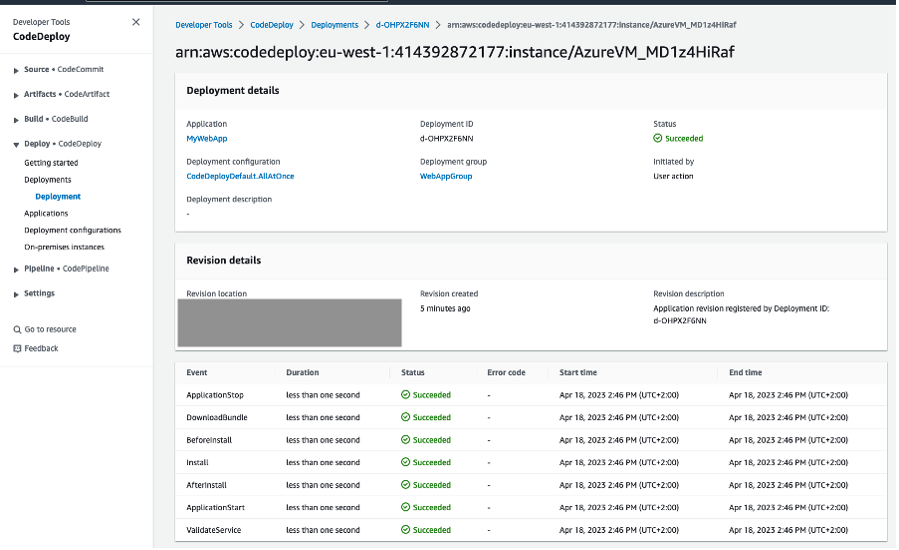
Upon successful completion of the pipeline execution, you can validate the deployment status in the CodeDeploy console. In this example, the successful CodeDeploy deployment looks like:

CodeDeploy Deployment details in AWS console

Figure 7: CodeDeploy Deployment details in AWS console

You can also validate the website URL in a browser to confirm if it’s working as expected. After completing the pipeline execution, hit the website URL on a browser to check if it’s working.

  • On the CloudFormation stack ‘aws-sample-app‘ Outputs tab, look for the WebsiteURL key and click on the URL.
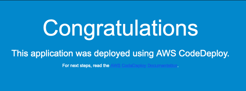
  • For a successful deployment, it will open a default page similar to Figure 8 below.
Sample application home page

Figure 8: Sample application home page

Cleanup

After you have tested and verified your pipeline, remove all resources created for this example to avoid incurring any unintended expenses.

Conclusion

In this blog post, we showed how to leverage the AWS Toolkit for Azure DevOps extension to deploy resources to your AWS account from Azure DevOps and perform a Blue/Green deployment using AWS CodeDeploy. We explored obtaining temporary credentials in AWS Identity and Access Management (IAM) by leveraging the AWS Security Token Service (AWS STS) with Azure managed identities and Azure App Registration. This approach enhances security by eliminating the need to store long-term credentials, adhering to best practices for credential management. For customers looking to host their code on GitHub and deploy to AWS, they can leverage GitHub Actions with AWS CodeBuild’s support for managed GitHub Action runners. This integration potentially helps to reduce costs and simplifying the operational overhead associated with CI/CD processes.

Author bio

Rakesh Singh

Rakesh is a Senior Technical Account Manager at Amazon supporting US EDTECH customers. He loves automation and enjoys working directly with customers to solve complex technical issues and provide architectural guidance related to Resilience and DevOps practices. Outside of work, he enjoys playing soccer, singing karaoke, and watching thriller movies.

Fault-isolated, zonal deployments with AWS CodeDeploy

Post Syndicated from Michael Haken original https://aws.amazon.com/blogs/devops/fault-isolated-zonal-deployments-with-aws-codedeploy/

In this blog post you’ll learn how to use a new feature in AWS CodeDeploy to deploy your application one Availability Zone (AZ) at a time to help increase the operational resilience or your services through improved fault isolation.

Introducing change to a system can be a time of risk. Even the most advanced CI/CD systems with comprehensive testing and phased deployments can still promote a bad change into production. A common approach to reduce this risk is using fractional deployments and closely monitoring critical metrics like availability and latency to gauge a deployment’s success. If the deployment shows signs of failure, the CI/CD system initiates an

This blog post will show you how to leverage CodeDeploy zonal deployments as part of a holistic AZ independent (AZI) architecture strategy, both patterns that many AWS service teams follow. With this feature, you no longer need to distinguish between infrastructure or deployment failures in order to respond to the event. You can use the same observability tools and recovery techniques for both, which allows you to contain the scope of impact to a single AZ and mitigate the impact more quickly and with less complexity. First, let’s define what an AZI architecture is so we can understand how this feature in CodeDeploy supports it.

Availability Zone independence

Fault isolation is an architectural pattern that limits the scope of impact of failures by creating independent fault containers that don’t share fate. It also allows you to quickly recover from failures by shifting traffic or resources away from the impaired fault container. AWS provides a number of different fault isolation boundaries, but the ones most people are familiar with are AZs and Regions. When you build multi-AZ architectures, you can design your application to implement AZI that uses the fault boundary provided by AZs to keep the interaction of resources isolated to their respective AZ (to the greatest extent possible).

A three tier Availability Zone indepdendent architecture deployed across three AZa

An Availability Zone independent (AZI) architecture implemented by disabling cross-zone load balancing and using an independent database read replica per AZ. Only database writes have to cross an AZ boundary.

The result is that the impacts from an impairment in one AZ don’t cascade to resources in other AZs, making the operation of your application in one AZ independent from events in the others. You should also monitor the health of each AZ independently, for example by looking at per-AZ load balancer HTTPCode_Target_5XX_Count metrics, or by sending synthetic requests to the load balancer nodes in each AZ and recording availability and latency metrics for each. When an event occurs that impacts your availability or latency in a single AZ, you can use capabilities like Amazon Route 53 Application Recovery Controller zonal shift to shift traffic away from that AZ to quickly mitigate impact, often in single-digit minutes.

Using zonal shift to shift traffic away from an single AZ

Using zonal shift to move traffic away from the AZ experiencing a service impairment

Traditional deployment strategy challenges

During an event, SRE, engineering, or operations teams can spend a lot of time trying to figure out if the source of impact is an infrastructure problem or related to a failed deployment. Then, based on the identified cause, they may take different mitigation actions. Thus, precious time is spent investigating the source of impact and deciding on the appropriate mitigation plan.

When the cause is due to a failed deployment, traditionally rollbacks are used to mitigate the problem. But rollbacks, even when automated, take time to complete. For example, let’s say your deployment batches take 5 minutes to complete, you deploy in 10% batches, and you’re halfway through a deployment to 100 instances when the rollback is initiated. This means it’s going to take at least 25 minutes to finish the rollback (5 batches, each taking 5 minutes to re-deploy to). And it’s entirely possible during that time that instances where the new software was deployed continue to pass health checks, but result in errors being returned to your customers. In the worst case, if all instances had been deployed to, this event could last for almost an hour with customers being impacted during the entire rollback process. In some cases, deployments can’t be rolled back and have to be rolled forward, meaning a new, updated version needs to be deployed to fix the previous deployment. Writing the code for the new deployment and testing it adds to the recovery time of your system and can be error prone.

Additionally, if your unit of deployment includes multiple AZs, then your potential scope of impact from a failed deployment isn’t predictably bounded. For example, if your CodeDeploy deployment groups target Amazon Elastic Compute Cloud (Amazon EC2) instances based on tags or an Amazon EC2 Auto Scaling group that spans multiple AZs, then you could see impact across the whole Region, even if you’re using fractional deployments. There’s not a smaller fault container that helps consistently limit the scope of impact to a predictable size.

Let’s look at how we can overcome these two challenges by using zonal deployments with CodeDeploy.

Zonal deployments with AWS CodeDeploy

One of the best practices we follow at AWS, described in My CI/CD pipeline is my release captain, is performing fractional deployments aligned to intended fault isolation boundaries, like individual hosts, cells, AZs, and Regions. When we release a change, the deployment is separated into waves, which represent fault containers (like Regions) that are deployed to in parallel, and those are further separated into stages. Within a single Region, the deployment starts with a one-box environment, representing a single host, then moves on to fractional batches (like 10% at a time) inside a single AZ, waits for a period of bake time, moves on to the next AZ, and so on until we’ve completed rolling out the change.

Four stages in a deployment pipeline showing per AZ deployments with bake time.

Deployment stages aligned to intended fault isolation boundaries within a single deployment wave for one Region

By aligning each stage to an expected fault isolation boundary, we create well-defined fault containers that provide an understood and bounded scope of impact in the case that something goes wrong with a deployment. You can take advantage of this same deployment strategy in your own applications by using zonal deployments in CodeDeploy. To utilize this capability, you need to define a custom deployment configuration shown below.

The configuration options for a CodeDeploy deployment configuration using a zonal configuration

Creating a zonal deployment configuration that deploys to 10% of the EC2 instances in each AZ at a time, one AZ at a time

This configuration defines a few important properties. First, it enables the zonal configuration, which ensures deployments will be phased one AZ at a time. In this case, updates will be deployed to batches of 10% of the instances in each AZ (see the minimum number of healthy instances per Availability Zone for more details on configuring this setting). Second, it defines a monitor duration, which is the bake time where the effects of the changes are observed before moving on to the next AZ. This ensures sufficient use of the new software to discover any potential bugs or problems before moving on. The value in this example is defined as 900 seconds, or 15 minutes. You should ensure this value is longer than the time it takes for your alarms to trigger. For example, if you are using an M of N alarm for availability and/or latency, that is using 3 data points out of 5 with 1-minute intervals, you need to make sure your bake time is set to greater than 600 seconds, otherwise, you might move on to the next AZ before your alarm has a chance to mark the deployment as unsuccessful. Finally, I’ve also defined a first zone monitor duration. This overrides the “monitor duration” for the first AZ being deployed to. This is useful since the first AZ is acting as our canary or one-box environment and we may want to wait additional time to be really confident the deployment is successful before moving on to the second AZ.

If your service is deployed behind a load balancer with cross-zone load balancing disabled (which is important to achieve AZI), carefully consider your batch size. The load balancer evenly splits traffic across AZs regardless of how many healthy hosts are in each AZ. Ensure your batch size is small enough that the temporary reduction in capacity during each batch doesn’t overwhelm the remaining instances in the same AZ. You can use the CodeDeploy minimum healthy hosts per AZ option to ensure there are enough healthy hosts in the AZ during a deployment batch or Elastic Load Balancing (ELB) target group minimum healthy target count with DNS failover to shift traffic away from the AZ if too few targets are present.

Recovering from a failed zonal deployment.

When a failure occurs, the highest priority is mitigating the impact, not fixing the root cause. While an automated rollback can help achieve both for a failed deployment, using a zonal shift can improve your recovery time. Let’s take a simple dashboard like the following figure. The top graph shows your availability as perceived by customers through using the regional endpoint of your load balancer like https://load-balancer-name-and-id.elb.us-east-1.amazonaws.com. The graphs below it show the measured availability from Amazon CloudWatch Synthetics canaries that test the load balancer endpoints in each AZ using endpoints like https://us-east-1a.load-balancer-name-and-id.elb.us-east-1.amazonaws.com.

Dashboards showing a drop in availability in one AZ that also impacts the regional customer experience

Dashboard showing impact in one AZ that affects the availability of the service

We can see that something starts impacting resources in AZ1 at 10:38 causing an availability drop. As we would expect, this impact is also seen by customers, shown in the top graph, but it’s unclear what the underlying cause of the availability drop is. Using the approach described in this post, it turns out that it doesn’t matter. Within a few minutes, at 10:41 the CloudWatch composite alarm monitoring the health of AZ1 transitions to the ALARM state and invokes a Lambda function that reads the alarm’s definition to get the AZ ID and ALB ARN involved, and initiates the zonal shift. It’s important that the alarm logic only reacts when a single AZ is impacted, if there was impact in more than one AZ, we would need to treat this as a Regional issue.

The process of identifying a failed deployment in a single AZ and responding with a zonal shift.

After a failed deployment to AZ1, an automatically initiated zonal shift quickly mitigates the customer impact

Then, after a few more minutes, at 10:44, we can see availability from the customer perspective has gone back up to 100% by shifting traffic away from AZ1.

Dashboards showing the regional customer experience has recovered while the AZ is still impacted by the failed deployment

The impact of the failed deployment is mitigated by shifting traffic away from AZ1

It turns out the cause of impact in this case was a failed deployment, and we can see that our synthetic canaries still see the failure while the deployment is rolling back, but we’ve achieved our primary goal of quickly removing the impact to the customer experience. From the start of impact to mitigation, 6 minutes elapsed, which was significantly faster than waiting for the deployment to completely rollback. After the rollback is complete, at 10:58, 20 minutes after the start of the event, we can see the alarm transition back to the OK state and availability return to normal in AZ1, meaning we can end the zonal shift and return to normal operation.

Dashboards showing that after the rollback is complete, the impact to the single AZ has also dissipated

After the deployment rollback is complete, the availability in AZ1 recovers and the zonal shift can be ended

Conclusion

Performing zonal deployments helps improve the effectiveness of AZI architectures. Aligning your deployments to your intended fault isolation boundaries, in this case AZs, creates a predictable scope of impact and helps prevents cascading failures. This in turn allows you to use a common set of observability and mitigation tools for both single-AZ infrastructure events and failed deployments, which can mitigate the impact faster than automated rollbacks. Additionally, by removing the ambiguity on selecting a recovery strategy for operators, it further reduces recovery time and complexity. Learn more about zonal deployments in AWS CodeDeploy here.

Michael Haken

Michael Haken

Michael is a Senior Principal Solutions Architect on the AWS Strategic Accounts team where he helps customers innovate, differentiate their business, and transform their customer experiences. He has 15 years’ experience supporting financial services, public sector, and digital native customers. Michael has his B.A. from UVA and M.S. in Computer Science from Johns Hopkins. Outside of work you’ll find him playing with his family and dogs on his farm.

Blue/Green Deployments to Amazon ECS using AWS CloudFormation and AWS CodeDeploy

Post Syndicated from Ajay Mehta original https://aws.amazon.com/blogs/devops/blue-green-deployments-to-amazon-ecs-using-aws-cloudformation-and-aws-codedeploy/

Introduction

Many customers use Amazon Elastic Container Service (ECS) for running their mission critical container-based applications on AWS. These customers are looking for safe deployment of application and infrastructure changes with minimal downtime, leveraging AWS CodeDeploy and AWS CloudFormation. AWS CloudFormation natively supports performing Blue/Green deployments on ECS using a CodeDeploy Blue/Green hook, but this feature comes with some additional considerations that are outlined here; one of them is the inability to use CloudFormation nested stacks, and another is the inability to update application and infrastructure changes in a single deployment. For these reasons, some customers may not be able to use the CloudFormation-based Blue/Green deployment capability for ECS. Additionally, some customers require more control over their Blue/Green deployment process and would therefore like CodeDeploy-based deployments to be performed outside of CloudFormation.

In this post, we will show you how to address these challenges by leveraging AWS CodeBuild and AWS CodePipeline to automate the configuration of CodeDeploy for performing Blue/Green deployments on ECS. We will also show how you can deploy both infrastructure and application changes through a single CodePipeline for your applications running on ECS.

The solution presented in this post is appropriate if you are using CloudFormation for your application infrastructure deployment. For AWS CDK applications, please refer to this post that walks through how you can enable Blue/Green deployments on ECS using CDK pipelines.

Reference Architecture

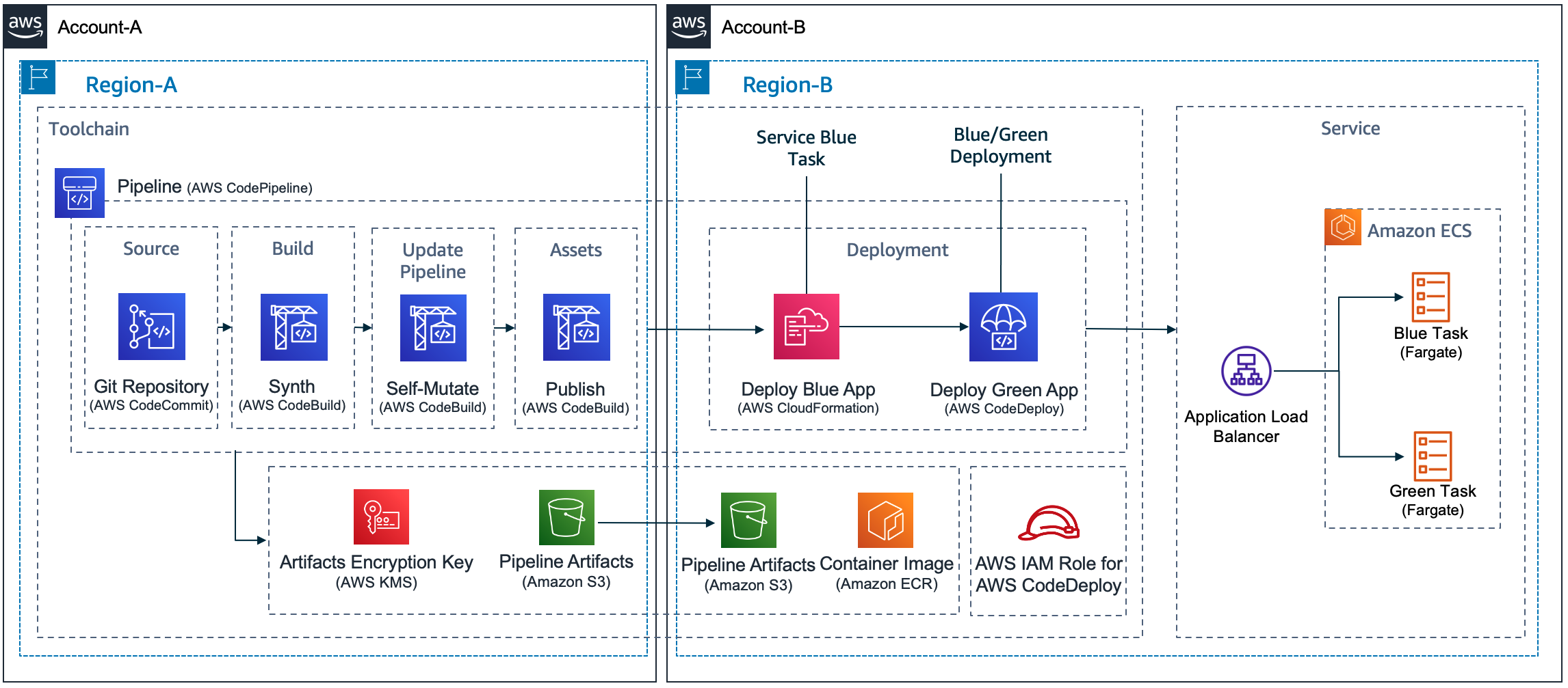
The diagram below shows a reference CICD pipeline for orchestrating a Blue/Green deployment for an ECS application. In this reference architecture, we assume that you are deploying both infrastructure and application changes through the same pipeline.

CICD Pipeline for performing Blue/Green deployment to an application running on ECS Fargate

Figure 1: CICD Pipeline for performing Blue/Green deployment to an application running on ECS Fargate Cluster

The pipeline consists of the following stages:

  1. Source: In the source stage, CodePipeline pulls the code from the source repository, such as AWS CodeCommit or GitHub, and stages the changes in S3.
  2. Build: In the build stage, you use CodeBuild to package CloudFormation templates, perform static analysis for the application code as well as the application infrastructure templates, run unit tests, build the application code, and generate and publish the application container image to ECR. These steps can be performed using a series of CodeBuild steps as described in the reference pipeline above.
  3. Deploy Infrastructure: In the deploy stage, you leverage CodePipeline’s CloudFormation deploy action to deploy or update the application infrastructure. In this stage, the entire application infrastructure is set up using CloudFormation nested stacks. This includes the components required to perform Blue/Green deployments on ECS using CodeDeploy, such as the ECS Cluster, ECS Service, Task definition, Application Load Balancer (ALB) listeners, target groups, CodeDeploy application, deployment group, and others.
  4. Deploy Application: In the deploy application stage, you use the CodePipeline ECS-to-CodeDeploy action to deploy your application changes using CodeDeploy’s blue/green deployment capability. By leveraging CodeDeploy, you can automate the blue/green deployment workflow for your applications running on ECS, including testing of your application after deployment and automated rollbacks in case of failed deployments. CodeDeploy also offers different ways to switch traffic for your application during a blue/green deployment by supporting Linear, Canary, and All-at-once traffic shifting options. More information on CodeDeploy’s Blue/Green deployment workflow for ECS can be found here

Considerations

Some considerations that you may need to account for when implementing the above reference pipeline

1. Creating the CodeDeploy deployment group using CloudFormation
For performing Blue/Green deployments using CodeDeploy on ECS, CloudFormation currently does not support creating the CodeDeploy components directly as these components are created and managed by CloudFormation through the AWS::CodeDeploy::BlueGreen hook. To work around this, you can leverage a CloudFormation custom resource implemented through an AWS Lambda function, to create the CodeDeploy Deployment group with the required configuration. A reference implementation of a CloudFormation custom resource lambda can be found in our solution’s reference implementation here.

2. Generating the required code deploy artifacts (appspec.yml and taskdef.json)
For leveraging the CodeDeployToECS action in CodePipeline, there are two input files (appspec.yml and taskdef.json) that are needed. These files/artifacts are used by CodePipeline to create a CodeDeploy deployment that performs Blue/Green deployment on your ECS cluster. The AppSpec file specifies an Amazon ECS task definition for the deployment, a container name and port mapping used to route traffic, and the Lambda functions that run after deployment lifecycle hooks. The container name must be a container in your Amazon ECS task definition. For more information on these, see Working with application revisions for CodeDeploy. The taskdef.json is used by CodePipeline to dynamically generate a new revision of the task definition with the updated application container image in ECR. This is an optional capability supported by the CodeDeployToECS action where it can automatically replace a place holder value (for example IMAGE1_NAME) for ImageUri in the taskdef.json with the Uri of the updated container Image. In the reference solution we do not use this capability as our taskdef.json contains the latest ImageUri that we plan to deploy. To create this taskdef.json, you can leverage CodeBuild to dynamically build the taskdef.json from the latest task definition ARN. Below are sample CodeBuild buildspec commands that creates the taskdef.json from ECS task definition

build:
    commands:
        # Create appspec.yml for CodeDeploy deployment
        - python iac/code-deploy/scripts/update-appspec.py --taskArn ${TASKDEF_ARN} --hooksLambdaArn ${HOOKS_LAMBDA_ARN} --inputAppSpecFile 'iac/code-deploy/appspec.yml' --outputAppSpecFile '/tmp/appspec.yml'
        # Create taskdefinition for CodeDeploy deployment
        - aws ecs describe-task-definition --task-definition ${TASKDEF_ARN} --region ${AWS_REGION} --query taskDefinition >> taskdef.json
    artifacts:
        files:
            - /tmp/appspec.yml
            - /tmp/taskdef.json
        discard-paths: yes

To generate the appspec.yml, you can leverage a python or shell script and a placeholder appspec.yml in your source repository to dynamically generate the updated appspec.yml file. For example, the below code snippet updates the placeholder values in an appspec.yml to generate an updated appspec.yml that is used in the deploy stage. In this example, we set the values of AfterAllowTestTraffic hook, the Container name, Container port values from task definition and Hooks Lambda ARN that is passed as input to the script.


  contents = yaml.safe_load(file)
  print(contents)
  response = ecs.describe_task_definition(taskDefinition=taskArn)
  contents['Hooks'][0]['AfterAllowTestTraffic'] = hooksLambdaArn
  contents['Resources'][0]['TargetService']['Properties']['LoadBalancerInfo']['ContainerName'] = response['taskDefinition']['containerDefinitions'][0]['name']
  contents['Resources'][0]['TargetService']['Properties']['LoadBalancerInfo']['ContainerPort'] = response['taskDefinition']['containerDefinitions'][0]['portMappings'][0]['containerPort']
  contents['Resources'][0]['TargetService']['Properties']['TaskDefinition'] = taskArn

  print('Updated appspec.yaml contents')
  yaml.dump(contents, outputFile)

In the above scenario, the existing task definition is used to build the appspec.yml. You can also specify one of more CodeDeploy lambda based hooks in the appspec.yml to perform variety of automated tests as part of your deployment.

3. Updates to the ECS task definition
To perform Blue/Green deployments on your ECS cluster using CodeDeploy, the deployment controller on the ECS Service needs to be set to CodeDeploy. With this configuration, any time there is an update to the task definition on the ECS service (such as when building new application image), the update results in a failure. This essentially causes CloudFormation updates to the application infrastructure to fail when new application changes are deployed. To avoid this, you can implement a CloudFormation based custom resource that obtains the previous version of task definition. This prevents CloudFormation from updating the ECS Service with new task definition when the application container image is updated and ultimately from failing the stack update. Updates to ECS Services for new task revisions are performed using the CodeDeploy deployment as outlined in #2 above. Using this mechanism, you can update the application infrastructure along with changes to the application code using a single pipeline while also leveraging CodeDeploy Blue/Green deployment.

4. Passing configuration between different stages of the pipeline
To create an automated pipeline that builds your infrastructure and performs a blue/green deployment for your application, you will need the ability to pass configuration between different stages of your pipeline. For example, when you want to create the taskdef.json and appspec.yml as mentioned in step #2, you need the ARN of the existing task definition and ARN of the CodeDeploy hook Lambda. These components are created in different stages within your pipeline. To facilitate this, you can leverage CodePipeline’s variables and namespaces. For example, in the CodePipeline stage below, we set the value of TASKDEF_ARN and HOOKS_LAMBDA_ARN environment variables by fetching those values from a different stage in the same pipeline where we create those components. An alternate option is to use AWS System Manager Parameter Store to store and retrieve that information. Additional information about CodePipeline’s variables and how to use them can be found in our documentation here.


- Name: BuildCodeDeployArtifacts
  Actions:
	- Name: BuildCodeDeployArtifacts
	  ActionTypeId:
		Category: Build
		Owner: AWS
		Provider: CodeBuild
		Version: "1"
	  Configuration:
		ProjectName: !Sub "${pApplicationName}-CodeDeployConfigBuild"
		EnvironmentVariables: '[{"name": "TASKDEF_ARN", "value": "#{DeployInfraVariables.oTaskDefinitionArn}", "type": "PLAINTEXT"},{"name": "HOOKS_LAMBDA_ARN", "value": "#{DeployInfraVariables.oAfterInstallHookLambdaArn}", "type": "PLAINTEXT"}]'
	  InputArtifacts:
		- Name: Source
	  OutputArtifacts:
		- Name: CodeDeployConfig
	  RunOrder: 1

Reference Solution:

As part of this post we have provided a reference solution that performs a Blue/Green deployment for a sample Java based application running on ECS Fargate using CodePipeline and CodeDeploy. The reference implementation provides CloudFormation templates to create the necessary CodeDeploy components, including custom resources for Blue/Green deployment on Amazon ECS, as well as the application infrastructure using nested stacks. The solution also provides a reference CodePipeline implementation that fully orchestrates the application build, test and blue/green deployment. In the solution we also demonstrate how you can orchestrate Blue/Green deployment using Linear, Canary, and All-at-once traffic shifting patterns. You can download the reference implementation from here. You can further customize this solution by building your own CodeDeploy lifecycle hooks and run additional configuration and validation tasks as per you application needs. We also recommend that you look at our Deployment Pipeline Reference Architecture (DPRA) and enhance your delivery pipelines by including additional stages and actions that meet your needs.

Conclusion:

In this post we walked through how you can automate Blue/Green deployment of your ECS based application leveraging AWS CodePipeline, AWS CodeDeploy and AWS CloudFormation nested stacks. We reviewed what you need to consider for automating Blue/Green deployment for your application running on your ECS cluster using CodePipeline and CodeDeploy and how you can address those challenges with some scripting and CloudFormation Lambda based custom resource. We hope that this helps you in configuring Blue/Green deployments on your ECS based application using CodePipeline and CodeDeploy.

Ajay Mehta is a Principal Cloud Infrastructure Architect for AWS Professional Services. He works with Enterprise customers accelerate their cloud adoption through building Landing Zones and transforming IT organizations to adopt cloud operating practices and agile operations. When not working he enjoys spending time with family, traveling, and exploring new places.

Santosh Kale is a Senior DevOps Architect at AWS Professional Services, passionate about Kubernetes and GenAI-AI/ML. As a DevOps and MLOps SME, he is an active member of AWS Containers, MLOps Area-of-Depth team and helps Enterprise High-Tech customers on their transformative journeys through DevOps/MLOps adoption and Containers modernization technologies. Beyond Cloud, he is a Nature Lover and enjoys quality time visiting scenic places around the world.

Multiple Load Balance Support in AWS CodeDeploy

Post Syndicated from Brian Beach original https://aws.amazon.com/blogs/devops/multiple-load-balance-support-in-codedeploy/

AWS CodeDeploy is a fully managed deployment service that automates software deployments to various compute services, such as Amazon Elastic Compute Cloud (Amazon EC2), Amazon Elastic Container Service (ECS), AWS Lambda, and on-premises servers. AWS CodeDeploy recently announced support for deploying to applications that use multiple AWS Elastic Load Balancers (ELB). CodeDeploy now supports multiple Classic Load Balancers (CLB), and multiple target groups associated with Application Load Balancers (ALB) or Network Load Balancer (NLB) when using CodeDeploy with Amazon EC2. In this blog post, I will show you how to deploy an application served by multiple load balancers.

Background

AWS CodeDeploy simplifies deploying application updates across Amazon EC2 instances registered with Elastic Load Balancers. The integration provides an automated, scalable way to deploy updates without affecting application availability.

To use CodeDeploy with load balancers, you install the CodeDeploy agent on Amazon EC2 instances that have been registered as targets of a Classic, Application, or Network Load Balancer. When creating a CodeDeploy deployment group, you specify the load balancer and target groups you want to deploy updates to.

During deployment, CodeDeploy safely shifts traffic by deregistering instances from the load balancer, deploying the new application revision, and then re-registering the instances to route traffic back. This approach ensures application capacity and availability are maintained throughout the deployment process. CodeDeploy coordinates the traffic shift across groups of instances, so that the deployment rolls out in a controlled fashion.

CodeDeploy offers two deployment approaches to choose from based on your needs: in-place deployments and blue/green deployments. With in-place deployments, traffic is shifted to the new application revision on the same set of instances. This allows performing rapid, incremental updates. Blue/green deployments involve shifting traffic to a separate fleet of instances running the new revision. This approach enables easy rollback if needed. CodeDeploy makes it easy to automate either deployment strategy across your infrastructure.

Architectures with Multiple Load Balancers

CodeDeploy’s expanded integration with Elastic Load Balancing unlocks new deployment flexibility. Users can now register multiple Classic Load Balancers and multiple target groups associated with Application or Network Load Balancers. This allows you to deploy updates across complex applications that leverage multiple target groups. For example, many customers run applications that serve both an internal audience and external audience. Often, these two audiences require different authentication and security requirements. It is common to provide access to the internal and external audiences through different load balancers, as shown in the following image.

Architecture showing two load balancers, one external facing and one internal facing

In the past, CodeDeploy only supported one load balancer per application. Customers running internal and external application tiers would have to duplicate environments, using separate EC2 instances and Amazon EC2 Auto Scaling groups for each audience. This resulted in overprovisioning and added overhead to manage duplicate resources.

With multiple load balancer support, CodeDeploy removes the need to duplicate environments. Users can now deploy updates to a single environment, and CodeDeploy will manage the deployment across both the internal and external load balancers. You simply select all the target groups used by your application, as shown in the following image.

CodeDeploy configuration showing two load balancers selected

This consolidated approach reduces infrastructure costs and operational complexity when automating deployments. CodeDeploy orchestrates the in-place or blue/green deployment across multiple load balanced target groups.

Migrating from a Classic Load Balancer

Many customers are migrating from Classic Load Balancers (CLB) to Application Load Balancers (ALB) or Network Load Balancers (NLB). ALB and NLB offer a more modern and advanced feature set than CLB, including integrated path-based and host-based routing, and native IPv6 support. They also deliver improved load balancing performance with higher throughput and lower latency. Other benefits include native integrations with AWS WAF, Shield, and Global Accelerator along with potential cost savings from requiring fewer load balancers. Overall, migrating to ALB or NLB provides an opportunity to gain advanced capabilities, better performance, tighter service integration, and reduced costs.

CodeDeploy’s new multi-target group capabilities streamline migrating from Classic Load Balancers (CLB) to Application or Network Load Balancers (ALB or NLB). Users can now deploy applications utilizing both legacy CLB and modern ALB or NLB in parallel during the transition. This enables gracefully testing integration with the new load balancers before fully cutting over. Once you verify that users have stopped using the CLB endpoint, you can delete the CLB.

During the transition period, CodeDeploy orchestrates deployments across the CLB and target groups tied to the ALB or NLB within a single automation. Users simply select the CLB and target groups of the new load balancer in the deployment group as shown in the following image.

CodeDeploy configuration showing a both a classic load balancer and target group selected

This consolidated approach lets CodeDeploy coordinate a staged rollout across CLB and ALB/NLB. With simplified management of multiple load balancers, CodeDeploy eases the critical process of modernizing infrastructure while maintaining application availability.

Conclusion

CodeDeploy’s expanded integration with Elastic Load Balancing allows more flexible application deployments. Support for multiple Classic Load Balancers and multiple target groups associated with Application or Network Load Balancers enables you to seamlessly update complex architectures on AWS. Whether you are consolidating disparate environments or migrating from Classic Load Balancers, CodeDeploy simplifies managing deployments across multiple load balanced tiers. To learn more, see Integrating CodeDeploy with Elastic Load Balancing in the AWS CodeDeploy Developer Guide or visit the CodeDeploy product page.

Blue/Green deployments using AWS CDK Pipelines and AWS CodeDeploy

Post Syndicated from Luiz Decaro original https://aws.amazon.com/blogs/devops/blue-green-deployments-using-aws-cdk-pipelines-and-aws-codedeploy/

Customers often ask for help with implementing Blue/Green deployments to Amazon Elastic Container Service (Amazon ECS) using AWS CodeDeploy. Their use cases usually involve cross-Region and cross-account deployment scenarios. These requirements are challenging enough on their own, but in addition to those, there are specific design decisions that need to be considered when using CodeDeploy. These include how to configure CodeDeploy, when and how to create CodeDeploy resources (such as Application and Deployment Group), and how to write code that can be used to deploy to any combination of account and Region.

Today, I will discuss those design decisions in detail and how to use CDK Pipelines to implement a self-mutating pipeline that deploys services to Amazon ECS in cross-account and cross-Region scenarios. At the end of this blog post, I also introduce a demo application, available in Java, that follows best practices for developing and deploying cloud infrastructure using AWS Cloud Development Kit (AWS CDK).

The Pipeline

CDK Pipelines is an opinionated construct library used for building pipelines with different deployment engines. It abstracts implementation details that developers or infrastructure engineers need to solve when implementing a cross-Region or cross-account pipeline. For example, in cross-Region scenarios, AWS CloudFormation needs artifacts to be replicated to the target Region. For that reason, AWS Key Management Service (AWS KMS) keys, an Amazon Simple Storage Service (Amazon S3) bucket, and policies need to be created for the secondary Region. This enables artifacts to be moved from one Region to another. In cross-account scenarios, CodeDeploy requires a cross-account role with access to the KMS key used to encrypt configuration files. This is the sort of detail that our customers want to avoid dealing with manually.

AWS CodeDeploy is a deployment service that automates application deployment across different scenarios. It deploys to Amazon EC2 instances, On-Premises instances, serverless Lambda functions, or Amazon ECS services. It integrates with AWS Identity and Access Management (AWS IAM), to implement access control to deploy or re-deploy old versions of an application. In the Blue/Green deployment type, it is possible to automate the rollback of a deployment using Amazon CloudWatch Alarms.

CDK Pipelines was designed to automate AWS CloudFormation deployments. Using AWS CDK, these CloudFormation deployments may include deploying application software to instances or containers. However, some customers prefer using CodeDeploy to deploy application software. In this blog post, CDK Pipelines will deploy using CodeDeploy instead of CloudFormation.

A pipeline build with CDK Pipelines that deploys to Amazon ECS using AWS CodeDeploy. It contains at least 5 stages: Source, Build, UpdatePipeline, Assets and at least one Deployment stage.

Design Considerations

In this post, I’m considering the use of CDK Pipelines to implement different use cases for deploying a service to any combination of accounts (single-account & cross-account) and regions (single-Region & cross-Region) using CodeDeploy. More specifically, there are four problems that need to be solved:

CodeDeploy Configuration

The most popular options for implementing a Blue/Green deployment type using CodeDeploy are using CloudFormation Hooks or using a CodeDeploy construct. I decided to operate CodeDeploy using its configuration files. This is a flexible design that doesn’t rely on using custom resources, which is another technique customers have used to solve this problem. On each run, a pipeline pushes a container to a repository on Amazon Elastic Container Registry (ECR) and creates a tag. CodeDeploy needs that information to deploy the container.

I recommend creating a pipeline action to scan the AWS CDK cloud assembly and retrieve the repository and tag information. The same action can create the CodeDeploy configuration files. Three configuration files are required to configure CodeDeploy: appspec.yaml, taskdef.json and imageDetail.json. This pipeline action should be executed before the CodeDeploy deployment action. I recommend creating template files for appspec.yaml and taskdef.json. The following script can be used to implement the pipeline action:

##
#!/bin/sh
#
# Action Configure AWS CodeDeploy
# It customizes the files template-appspec.yaml and template-taskdef.json to the environment
#
# Account = The target Account Id
# AppName = Name of the application
# StageName = Name of the stage
# Region = Name of the region (us-east-1, us-east-2)
# PipelineId = Id of the pipeline
# ServiceName = Name of the service. It will be used to define the role and the task definition name
#
# Primary output directory is codedeploy/. All the 3 files created (appspec.json, imageDetail.json and 
# taskDef.json) will be located inside the codedeploy/ directory
#
##
Account=$1
Region=$2
AppName=$3
StageName=$4
PipelineId=$5
ServiceName=$6
repo_name=$(cat assembly*$PipelineId-$StageName/*.assets.json | jq -r '.dockerImages[] | .destinations[] | .repositoryName' | head -1) 
tag_name=$(cat assembly*$PipelineId-$StageName/*.assets.json | jq -r '.dockerImages | to_entries[0].key')  
echo ${repo_name} 
echo ${tag_name} 
printf '{"ImageURI":"%s"}' "$Account.dkr.ecr.$Region.amazonaws.com/${repo_name}:${tag_name}" > codedeploy/imageDetail.json                     
sed 's#APPLICATION#'$AppName'#g' codedeploy/template-appspec.yaml > codedeploy/appspec.yaml 
sed 's#APPLICATION#'$AppName'#g' codedeploy/template-taskdef.json | sed 's#TASK_EXEC_ROLE#arn:aws:iam::'$Account':role/'$ServiceName'#g' | sed 's#fargate-task-definition#'$ServiceName'#g' > codedeploy/taskdef.json 
cat codedeploy/appspec.yaml
cat codedeploy/taskdef.json
cat codedeploy/imageDetail.json

Using a Toolchain

A good strategy is to encapsulate the pipeline inside a Toolchain to abstract how to deploy to different accounts and regions. This helps decoupling clients from the details such as how the pipeline is created, how CodeDeploy is configured, and how cross-account and cross-Region deployments are implemented. To create the pipeline, deploy a Toolchain stack. Out-of-the-box, it allows different environments to be added as needed. Depending on the requirements, the pipeline may be customized to reflect the different stages or waves that different components might require. For more information, please refer to our best practices on how to automate safe, hands-off deployments and its reference implementation.

In detail, the Toolchain stack follows the builder pattern used throughout the CDK for Java. This is a convenience that allows complex objects to be created using a single statement:

 Toolchain.Builder.create(app, Constants.APP_NAME+"Toolchain")
        .stackProperties(StackProps.builder()
                .env(Environment.builder()
                        .account(Demo.TOOLCHAIN_ACCOUNT)
                        .region(Demo.TOOLCHAIN_REGION)
                        .build())
                .build())
        .setGitRepo(Demo.CODECOMMIT_REPO)
        .setGitBranch(Demo.CODECOMMIT_BRANCH)
        .addStage(
                "UAT",
                EcsDeploymentConfig.CANARY_10_PERCENT_5_MINUTES,
                Environment.builder()
                        .account(Demo.SERVICE_ACCOUNT)
                        .region(Demo.SERVICE_REGION)
                        .build())                                                                                                             
        .build();

In the statement above, the continuous deployment pipeline is created in the TOOLCHAIN_ACCOUNT and TOOLCHAIN_REGION. It implements a stage that builds the source code and creates the Java archive (JAR) using Apache Maven.  The pipeline then creates a Docker image containing the JAR file.

The UAT stage will deploy the service to the SERVICE_ACCOUNT and SERVICE_REGION using the deployment configuration CANARY_10_PERCENT_5_MINUTES. This means 10 percent of the traffic is shifted in the first increment and the remaining 90 percent is deployed 5 minutes later.

To create additional deployment stages, you need a stage name, a CodeDeploy deployment configuration and an environment where it should deploy the service. As mentioned, the pipeline is, by default, a self-mutating pipeline. For example, to add a Prod stage, update the code that creates the Toolchain object and submit this change to the code repository. The pipeline will run and update itself adding a Prod stage after the UAT stage. Next, I show in detail the statement used to add a new Prod stage. The new stage deploys to the same account and Region as in the UAT environment:

... 
        .addStage(
                "Prod",
                EcsDeploymentConfig.CANARY_10_PERCENT_5_MINUTES,
                Environment.builder()
                        .account(Demo.SERVICE_ACCOUNT)
                        .region(Demo.SERVICE_REGION)
                        .build())                                                                                                                                      
        .build();

In the statement above, the Prod stage will deploy new versions of the service using a CodeDeploy deployment configuration CANARY_10_PERCENT_5_MINUTES. It means that 10 percent of traffic is shifted in the first increment of 5 minutes. Then, it shifts the rest of the traffic to the new version of the application. Please refer to Organizing Your AWS Environment Using Multiple Accounts whitepaper for best-practices on how to isolate and manage your business applications.

Some customers might find this approach interesting and decide to provide this as an abstraction to their application development teams. In this case, I advise creating a construct that builds such a pipeline. Using a construct would allow for further customization. Examples are stages that promote quality assurance or deploy the service in a disaster recovery scenario.

The implementation creates a stack for the toolchain and another stack for each deployment stage. As an example, consider a toolchain created with a single deployment stage named UAT. After running successfully, the DemoToolchain and DemoService-UAT stacks should be created as in the next image:

Two stacks are needed to create a Pipeline that deploys to a single environment. One stack deploys the Toolchain with the Pipeline and another stack deploys the Service compute infrastructure and CodeDeploy Application and DeploymentGroup. In this example, for an application named Demo that deploys to an environment named UAT, the stacks deployed are: DemoToolchain and DemoService-UAT

CodeDeploy Application and Deployment Group

CodeDeploy configuration requires an application and a deployment group. Depending on the use case, you need to create these in the same or in a different account from the toolchain (pipeline). The pipeline includes the CodeDeploy deployment action that performs the blue/green deployment. My recommendation is to create the CodeDeploy application and deployment group as part of the Service stack. This approach allows to align the lifecycle of CodeDeploy application and deployment group with the related Service stack instance.

CodePipeline allows to create a CodeDeploy deployment action that references a non-existing CodeDeploy application and deployment group. This allows us to implement the following approach:

  • Toolchain stack deploys the pipeline with CodeDeploy deployment action referencing a non-existing CodeDeploy application and deployment group
  • When the pipeline executes, it first deploys the Service stack that creates the related CodeDeploy application and deployment group
  • The next pipeline action executes the CodeDeploy deployment action. When the pipeline executes the CodeDeploy deployment action, the related CodeDeploy application and deployment will already exist.

Below is the pipeline code that references the (initially non-existing) CodeDeploy application and deployment group.

private IEcsDeploymentGroup referenceCodeDeployDeploymentGroup(
        final Environment env, 
        final String serviceName, 
        final IEcsDeploymentConfig ecsDeploymentConfig, 
        final String stageName) {

    IEcsApplication codeDeployApp = EcsApplication.fromEcsApplicationArn(
            this,
            Constants.APP_NAME + "EcsCodeDeployApp-"+stageName,
            Arn.format(ArnComponents.builder()
                    .arnFormat(ArnFormat.COLON_RESOURCE_NAME)
                    .partition("aws")
                    .region(env.getRegion())
                    .service("codedeploy")
                    .account(env.getAccount())
                    .resource("application")
                    .resourceName(serviceName)
                    .build()));

    IEcsDeploymentGroup deploymentGroup = EcsDeploymentGroup.fromEcsDeploymentGroupAttributes(
            this,
            Constants.APP_NAME + "-EcsCodeDeployDG-"+stageName,
            EcsDeploymentGroupAttributes.builder()
                    .deploymentGroupName(serviceName)
                    .application(codeDeployApp)
                    .deploymentConfig(ecsDeploymentConfig)
                    .build());

    return deploymentGroup;
}

To make this work, you should use the same application name and deployment group name values when creating the CodeDeploy deployment action in the pipeline and when creating the CodeDeploy application and deployment group in the Service stack (where the Amazon ECS infrastructure is deployed). This approach is necessary to avoid a circular dependency error when trying to create the CodeDeploy application and deployment group inside the Service stack and reference these objects to configure the CodeDeploy deployment action inside the pipeline. Below is the code that uses Service stack construct ID to name the CodeDeploy application and deployment group. I set the Service stack construct ID to the same name I used when creating the CodeDeploy deployment action in the pipeline.

   // configure AWS CodeDeploy Application and DeploymentGroup
   EcsApplication app = EcsApplication.Builder.create(this, "BlueGreenApplication")
           .applicationName(id)
           .build();

   EcsDeploymentGroup.Builder.create(this, "BlueGreenDeploymentGroup")
           .deploymentGroupName(id)
           .application(app)
           .service(albService.getService())
           .role(createCodeDeployExecutionRole(id))
           .blueGreenDeploymentConfig(EcsBlueGreenDeploymentConfig.builder()
                   .blueTargetGroup(albService.getTargetGroup())
                   .greenTargetGroup(tgGreen)
                   .listener(albService.getListener())
                   .testListener(listenerGreen)
                   .terminationWaitTime(Duration.minutes(15))
                   .build())
           .deploymentConfig(deploymentConfig)
           .build();

CDK Pipelines roles and permissions

CDK Pipelines creates roles and permissions the pipeline uses to execute deployments in different scenarios of regions and accounts. When using CodeDeploy in cross-account scenarios, CDK Pipelines deploys a cross-account support stack that creates a pipeline action role for the CodeDeploy action. This cross-account support stack is defined in a JSON file that needs to be published to the AWS CDK assets bucket in the target account. If the pipeline has the self-mutation feature on (default), the UpdatePipeline stage will do a cdk deploy to deploy changes to the pipeline. In cross-account scenarios, this deployment also involves deploying/updating the cross-account support stack. For this, the SelfMutate action in UpdatePipeline stage needs to assume CDK file-publishing and a deploy roles in the remote account.

The IAM role associated with the AWS CodeBuild project that runs the UpdatePipeline stage does not have these permissions by default. CDK Pipelines cannot grant these permissions automatically, because the information about the permissions that the cross-account stack needs is only available after the AWS CDK app finishes synthesizing. At that point, the permissions that the pipeline has are already locked-in­­. Hence, for cross-account scenarios, the toolchain should extend the permissions of the pipeline’s UpdatePipeline stage to include the file-publishing and deploy roles.

In cross-account environments it is possible to manually add these permissions to the UpdatePipeline stage. To accomplish that, the Toolchain stack may be used to hide this sort of implementation detail. In the end, a method like the one below can be used to add these missing permissions. For each different mapping of stage and environment in the pipeline it validates if the target account is different than the account where the pipeline is deployed. When the criteria is met, it should grant permission to the UpdatePipeline stage to assume CDK bootstrap roles (tagged using key aws-cdk:bootstrap-role) in the target account (with the tag value as file-publishing or deploy). The example below shows how to add permissions to the UpdatePipeline stage:

private void grantUpdatePipelineCrossAccoutPermissions(Map<String, Environment> stageNameEnvironment) {

    if (!stageNameEnvironment.isEmpty()) {

        this.pipeline.buildPipeline();
        for (String stage : stageNameEnvironment.keySet()) {

            HashMap<String, String[]> condition = new HashMap<>();
            condition.put(
                    "iam:ResourceTag/aws-cdk:bootstrap-role",
                    new String[] {"file-publishing", "deploy"});
            pipeline.getSelfMutationProject()
                    .getRole()
                    .addToPrincipalPolicy(PolicyStatement.Builder.create()
                            .actions(Arrays.asList("sts:AssumeRole"))
                            .effect(Effect.ALLOW)
                            .resources(Arrays.asList("arn:*:iam::"
                                    + stageNameEnvironment.get(stage).getAccount() + ":role/*"))
                            .conditions(new HashMap<String, Object>() {{
                                    put("ForAnyValue:StringEquals", condition);
                            }})
                            .build());
        }
    }
}

The Deployment Stage

Let’s consider a pipeline that has a single deployment stage, UAT. The UAT stage deploys a DemoService. For that, it requires four actions: DemoService-UAT (Prepare and Deploy), ConfigureBlueGreenDeploy and Deploy.

When using CodeDeploy the deployment stage is expected to have four actions: two actions to create CloudFormation change set and deploy the ECS or compute infrastructure, an action to configure CodeDeploy and the last action that deploys the application using CodeDeploy. In the diagram, these are (in the diagram in the respective order): DemoService-UAT.Prepare and DemoService-UAT.Deploy, ConfigureBlueGreenDeploy and Deploy.

The
DemoService-UAT.Deploy action will create the ECS resources and the CodeDeploy application and deployment group. The
ConfigureBlueGreenDeploy action will read the AWS CDK
cloud assembly. It uses the configuration files to identify the Amazon Elastic Container Registry (Amazon ECR) repository and the container image tag pushed. The pipeline will send this information to the
Deploy action.  The
Deploy action starts the deployment using CodeDeploy.

Solution Overview

As a convenience, I created an application, written in Java, that solves all these challenges and can be used as an example. The application deployment follows the same 5 steps for all deployment scenarios of account and Region, and this includes the scenarios represented in the following design:

A pipeline created by a Toolchain should be able to deploy to any combination of accounts and regions. This includes four scenarios: single-account and single-Region, single-account and cross-Region, cross-account and single-Region and cross-account and cross-Region

Conclusion

In this post, I identified, explained and solved challenges associated with the creation of a pipeline that deploys a service to Amazon ECS using CodeDeploy in different combinations of accounts and regions. I also introduced a demo application that implements these recommendations. The sample code can be extended to implement more elaborate scenarios. These scenarios might include automated testing, automated deployment rollbacks, or disaster recovery. I wish you success in your transformative journey.

Luiz Decaro

Luiz is a Principal Solutions architect at Amazon Web Services (AWS). He focuses on helping customers from the Financial Services Industry succeed in the cloud. Luiz holds a master’s in software engineering and he triggered his first continuous deployment pipeline in 2005.

How to deploy workloads in a multicloud environment with AWS developer tools

Post Syndicated from Brent Van Wynsberge original https://aws.amazon.com/blogs/devops/how-to-deploy-workloads-in-a-multicloud-environment-with-aws-developer-tools/

As organizations embrace cloud computing as part of “cloud first” strategy, and migrate to the cloud, some of the enterprises end up in a multicloud environment.  We see that enterprise customers get the best experience, performance and cost structure when they choose a primary cloud provider. However, for a variety of reasons, some organizations end up operating in a multicloud environment. For example, in case of mergers & acquisitions, an organization may acquire an entity which runs on a different cloud platform, resulting in the organization operating in a multicloud environment. Another example is in the case where an ISV (Independent Software Vendor) provides services to customers operating on different cloud providers. One more example is the scenario where an organization needs to adhere to data residency and data sovereignty requirements, and ends up with workloads deployed to multiple cloud platforms across locations. Thus, the organization ends up running in a multicloud environment.

In the scenarios described above, one of the challenges organizations face operating such a complex environment is managing release process (building, testing, and deploying applications at scale) across multiple cloud platforms. If an organization’s primary cloud provider is AWS, they may want to continue using AWS developer tools to deploy workloads in other cloud platforms. Organizations facing such scenarios can leverage AWS services to develop their end-to-end CI/CD and release process instead of developing a release pipeline for each platform, which is complex, and not sustainable in the long run.

In this post we show how organizations can continue using AWS developer tools in a hybrid and multicloud environment. We walk the audience through a scenario where we deploy an application to VMs running on-premises and Azure, showcasing AWS’ hybrid and multicloud DevOps capabilities.

Solution and scenario overview

In this post we’re demonstrating the following steps:

  • Setup a CI/CD pipeline using AWS CodePipeline, and show how it’s run when application code is updated, and checked into the code repository (GitHub).
  • Check out application code from the code repository, and use an IDE (Visual Studio Code) to make changes, and check-in the code to the code repository.
  • Check in the modified application code to automatically run the release process built using AWS CodePipeline. It makes use of AWS CodeBuild to retrieve the latest version of code from code repository, compile it, build the deployment package, and test the application.
  • Deploy the updated application to VMs across on-premises, and Azure using AWS CodeDeploy.

The high-level solution is shown below. This post does not show all of the possible combinations and integrations available to build the CI/CD pipeline. As an example, you can integrate the pipeline with your existing tools for test and build such as Selenium, Jenkins, SonarQube etc.

This post focuses on deploying application in a multicloud environment, and how AWS Developer Tools can support virtually any scenario or use case specific to your organization. We will be deploying a sample application from this AWS tutorial to an on-premises server, and an Azure Virtual Machine (VM) running Red Hat Enterprise Linux (RHEL). In future posts in this series, we will cover how you can deploy any type of workload using AWS tools, including containers, and serverless applications.

Architecture Diagram

CI/CD pipeline setup

This section describes instructions for setting up a multicloud CI/CD pipeline.

Note: A key point to note is that the CI/CD pipeline setup, and related sub-sections in this post, are a one-time activity, and you’ll not need to perform these steps every time an application is deployed or modified.

Install CodeDeploy agent

The AWS CodeDeploy agent is a software package that is used to execute deployments on an instance. You can install the CodeDeploy agent on an on-premises server and Azure VM by either using the command line, or AWS Systems Manager.

Setup GitHub code repository

Setup GitHub code repository using the following steps:

  1. Create a new GitHub code repository or use a repository that already exists.
  2. Copy the Sample_App_Linux app (zip) from Amazon S3 as described in Step 3 of Upload a sample application to your GitHub repository tutorial.
  3. Commit the files to code repository
    git add .
    git commit -m 'Initial Commit'
    git push

You will use this repository to deploy your code across environments.

Configure AWS CodePipeline

Follow the steps outlined below to setup and configure CodePipeline to orchestrate the CI/CD pipeline of our application.

  1. Navigate to CodePipeline in the AWS console and click on ‘Create pipeline’
  2. Give your pipeline a name (eg: MyWebApp-CICD) and allow CodePipeline to create a service role on your behalf.
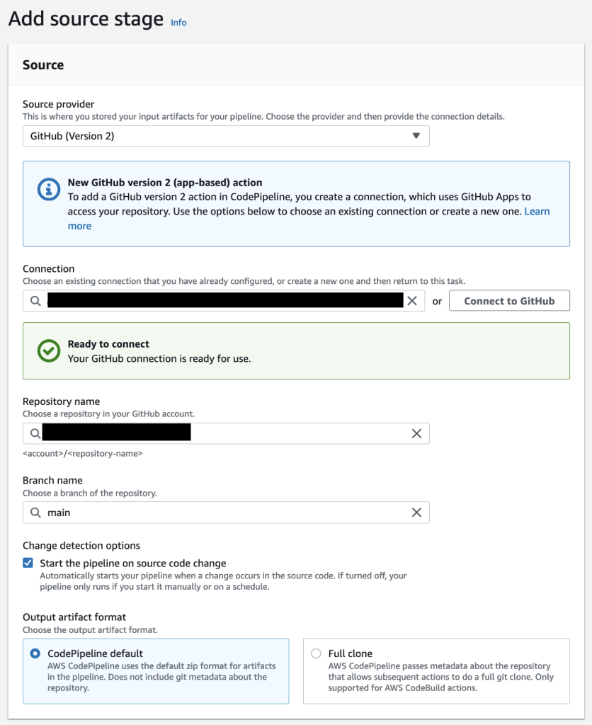
  3. For the source stage, select GitHub (v2) as your source provide and click on the Connect to GitHub button to give CodePipeline access to your git repository.
  4. Create a new GitHub connection and click on the Install a new App button to install the AWS Connector in your GitHub account.
  5. Back in the CodePipeline console select the repository and branch you would like to build and deploy.

Image showing the configured source stage

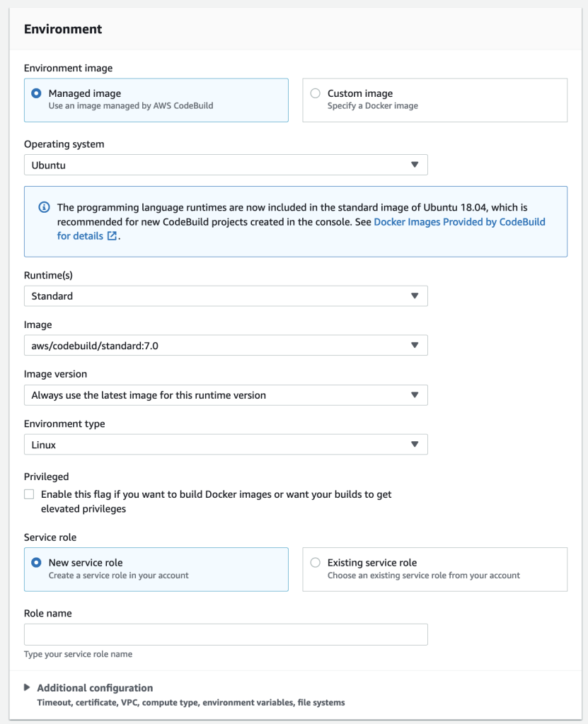
  1. Now we create the build stage; Select AWS CodeBuild as the build provider.
  2. Click on the ‘Create project’ button to create the project for your build stage, and give your project a name.
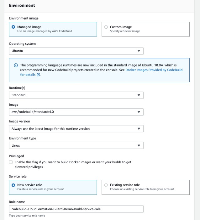
  3. Select Ubuntu as the operating system for your managed image, chose the standard runtime and select the ‘aws/codebuild/standard’ image with the latest version.

Image showing the configured environment

  1. In the Buildspec section select “Insert build commands” and click on switch to editor. Enter the following yaml code as your build commands:
version: 0.2
phases:
    build:
        commands:
            - echo "This is a dummy build command"
artifacts:
    files:
        - "*/*"

Note: you can also integrate build commands to your git repository by using a buildspec yaml file. More information can be found at Build specification reference for CodeBuild.

  1. Leave all other options as default and click on ‘Continue to CodePipeline’

Image showing the configured buildspec

  1. Back in the CodePipeline console your Project name will automatically be filled in. You can now continue to the next step.
  2. Click the “Skip deploy stage” button; We will create this in the next section.
  3. Review your changes and click “Create pipeline”. Your newly created pipeline will now build for the first time!

Image showing the first execution of the CI/CD pipeline

Configure AWS CodeDeploy on Azure and on-premises VMs

Now that we have built our application, we want to deploy it to both the environments – Azure, and on-premises. In the “Install CodeDeploy agent” section we’ve already installed the CodeDeploy agent. As a one-time step we now have to give the CodeDeploy agents access to the AWS environment.  You can leverage AWS Identity and Access Management (IAM) Roles Anywhere in combination with the code-deploy-session-helper to give access to the AWS resources needed.
The IAM Role should at least have the AWSCodeDeployFullAccess AWS managed policy and Read only access to the CodePipeline S3 bucket in your account (called codepipeline-<region>-<account-id>) .

For more information on how to setup IAM Roles Anywhere please refer how to extend AWS IAM roles to workloads outside of AWS with IAM Roles Anywhere. Alternative ways to configure access can be found in the AWS CodeDeploy user guide. Follow the steps below for instances you want to configure.

  1. Configure your CodeDeploy agent as described in the user guide. Ensure the AWS Command Line Interface (CLI) is installed on your VM and execute the following command to register the instance with CodeDeploy.
    aws deploy register-on-premises-instance --instance-name <name_for_your_instance> --iam-role-arn <arn_of_your_iam_role>
  1. Tag the instance as follows
    aws deploy add-tags-to-on-premises-instances --instance-names <name_for_your_instance> --tags Key=Application,Value=MyWebApp
  2. You should now see both instances registered in the “CodeDeploy > On-premises instances” panel. You can now deploy application to your Azure VM and on premises VMs!

Image showing the registered instances

Configure AWS CodeDeploy to deploy WebApp

Follow the steps mentioned below to modify the CI/CD pipeline to deploy the application to Azure, and on-premises environments.

  1. Create an IAM role named CodeDeployServiceRole and select CodeDeploy > CodeDeploy as your use case. IAM will automatically select the right policy for you. CodeDeploy will use this role to manage the deployments of your application.
  2. In the AWS console navigate to CodeDeploy > Applications. Click on “Create application”.
  3. Give your application a name and choose “EC2/On-premises” as the compute platform.
  4. Configure the instances we want to deploy to. In the detail view of your application click on “Create deployment group”.
  5. Give your deployment group a name and select the CodeDeployServiceRole.
  6. In the environment configuration section choose On-premises Instances.
  7. Configure the Application, MyWebApp key value pair.
  8. Disable load balancing and leave all other options default.
  9. Click on create deployment group. You should now see your newly created deployment group.

Image showing the created CodeDeploy Application and Deployment group

  1. We can now edit our pipeline to deploy to the newly created deployment group.
  2. Navigate to your previously created Pipeline in the CodePipeline section and click edit. Add the deploy stage by clicking on Add stage and name it Deploy. Aftewards click Add action.
  3. Name your action and choose CodeDeploy as your action provider.
  4. Select “BuildArtifact” as your input artifact and select your newly created application and deployment group.
  5. Click on Done and on Save in your pipeline to confirm the changes. You have now added the deploy step to your pipeline!

Image showing the updated pipeline

This completes the on-time devops pipeline setup, and you will not need to repeat the process.

Automated DevOps pipeline in action

This section demonstrates how the devops pipeline operates end-to-end, and automatically deploys application to Azure VM, and on-premises server when the application code changes.

  1. Click on Release Change to deploy your application for the first time. The release change button manually triggers CodePipeline to update your code. In the next section we will make changes to the repository which triggers the pipeline automatically.
  2. During the “Source” stage your pipeline fetches the latest version from github.
  3. During the “Build” stage your pipeline uses CodeBuild to build your application and generate the deployment artifacts for your pipeline. It uses the buildspec.yml file to determine the build steps.
  4. During the “Deploy” stage your pipeline uses CodeDeploy to deploy the build artifacts to the configured Deployment group – Azure VM and on-premises VM. Navigate to the url of your application to see the results of the deployment process.

Image showing the deployed sample application


Update application code in IDE

You can modify the application code using your favorite IDE. In this example we will change the background color and a paragraph of the sample application.

Image showing modifications being made to the file

Once you’ve modified the code, save the updated file followed by pushing the code to the code repository.

git add .
git commit -m "I made changes to the index.html file "
git push

DevOps pipeline (CodePipeline) – compile, build, and test

Once the code is updated, and pushed to GitHub, the DevOps pipeline (CodePipeline) automatically compiles, builds and tests the modified application. You can navigate to your pipeline (CodePipeline) in the AWS Console, and should see the pipeline running (or has recently completed). CodePipeline automatically executes the Build and Deploy steps. In this case we’re not adding any complex logic, but based on your organization’s requirements you can add any build step, or integrate with other tools.

Image showing CodePipeline in action

Deployment process using CodeDeploy

In this section, we describe how the modified application is deployed to the Azure, and on-premises VMs.

  1. Open your pipeline in the CodePipeline console, and click on the “AWS CodeDeploy” link in the Deploy step to navigate to your deployment group. Open the “Deployments” tab.

Image showing application deployment history

  1. Click on the first deployment in the Application deployment history section. This will show the details of your latest deployment.

Image showing deployment lifecycle events for the deployment

  1. In the “Deployment lifecycle events” section click on one of the “View events” links. This shows you the lifecycle steps executed by CodeDeploy and will display the error log output if any of the steps have failed.

Image showing deployment events on instance

  1. Navigate back to your application. You should now see your changes in the application. You’ve successfully set up a multicloud DevOps pipeline!

Image showing a new version of the deployed application

Conclusion

In summary, the post demonstrated how AWS DevOps tools and services can help organizations build a single release pipeline to deploy applications and workloads in a hybrid and multicloud environment. The post also showed how to set up CI/CD pipeline to deploy applications to AWS, on-premises, and Azure VMs.

If you have any questions or feedback, leave them in the comments section.

About the Authors

Picture of Amandeep

Amandeep Bajwa

Amandeep Bajwa is a Senior Solutions Architect at AWS supporting Financial Services enterprises. He helps organizations achieve their business outcomes by identifying the appropriate cloud transformation strategy based on industry trends, and organizational priorities. Some of the areas Amandeep consults on are cloud migration, cloud strategy (including hybrid & multicloud), digital transformation, data & analytics, and technology in general.

Picture of Pawan

Pawan Shrivastava

Pawan Shrivastava is a Partner Solution Architect at AWS in the WWPS team. He focusses on working with partners to provide technical guidance on AWS, collaborate with them to understand their technical requirements, and designing solutions to meet their specific needs. Pawan is passionate about DevOps, automation and CI CD pipelines. He enjoys watching mma, playing cricket and working out in the gym.

Picture of Brent

Brent Van Wynsberge

Brent Van Wynsberge is a Solutions Architect at AWS supporting enterprise customers. He guides organizations in their digital transformation and innovation journey and accelerates cloud adoption. Brent is an IoT enthusiast, specifically in the application of IoT in manufacturing, he is also interested in DevOps, data analytics, containers, and innovative technologies in general.

Picture of Mike

Mike Strubbe

Mike is a Cloud Solutions Architect Manager at AWS with a strong focus on cloud strategy, digital transformation, business value, leadership, and governance. He helps Enterprise customers achieve their business goals through cloud expertise, coupled with strong business acumen skills. Mike is passionate about implementing cloud strategies that enable cloud transformations, increase operational efficiency and drive business value.

Use the AWS Toolkit for Azure DevOps to automate your deployments to AWS

Post Syndicated from Mahmoud Abid original https://aws.amazon.com/blogs/devops/use-the-aws-toolkit-for-azure-devops-to-automate-your-deployments-to-aws/

Many developers today seek to improve productivity by finding better ways to collaborate, enhance code quality and automate repetitive tasks. We hear from some of our customers that they would like to leverage services such as AWS CloudFormation, AWS CodeBuild and other AWS Developer Tools to manage their AWS resources while continuing to use their existing CI/CD pipelines which they are familiar with. These services range from popular open-source solutions, such as Jenkins, to paid commercial solutions, such as Azure DevOps Server (formerly Team Foundation Server (TFS)).

In this post, I will walk you through an example to leverage the AWS Toolkit for Azure DevOps to deploy your Infrastructure as Code templates, i.e. AWS CloudFormation stacks, directly from your existing Azure DevOps build pipelines.

The AWS Toolkit for Azure DevOps is a free-to-use extension for hosted and on-premises Microsoft Azure DevOps that makes it easy to manage and deploy applications using AWS. It integrates with many AWS services, including Amazon S3, AWS CodeDeploy, AWS Lambda, AWS CloudFormation, Amazon SQS and others. It can also run commands using the AWS Tools for Windows PowerShell module as well as the AWS CLI.

Solution Overview

The solution described in this post consists of leveraging the AWS Toolkit for Azure DevOps to manage resources on AWS via Infrastructure as Code templates with AWS CloudFormation:

Solution high-level overview

Figure 1. Solution high-level overview

Prerequisites and Assumptions

You will need to go through three main steps in order to set up your environment, which are summarized here and detailed in the toolkit’s user guide:

  • Install the toolkit into your Azure DevOps account or choose Download to install it on an on-premises server (Figure 2).
  • Create an IAM User and download its keys. Keep the principle of least privilege in mind when associating the policy to your user.
  • Create a Service Connection for your project in Azure DevOps. Service connections are how the Azure DevOps tooling manages connecting and providing access to Azure resources. The AWS Toolkit also provides a user interface to configure the AWS credentials used by the service connection (Figure 3).

In addition to the above steps, you will need a sample AWS CloudFormation template to use for testing the deployment such as this sample template creating an EC2 instance. You can find more samples in the Sample Templates page or get started with authoring your own templates.

AWS Toolkit for Azure DevOps in the Visual Studio Marketplace

Figure 2. AWS Toolkit for Azure DevOps in the Visual Studio Marketplace

A new Service Connection of type “AWS” will appear after installing the extension

Figure 3. A new Service Connection of type “AWS” will appear after installing the extension

Model your CI/CD Pipeline to Automate Your Deployments on AWS

One common DevOps model is to have a CI/CD pipeline that deploys an application stack from one environment to another. This model typically includes a Development (or integration) account first, then Staging and finally a Production environment. Let me show you how to make some changes to the service connection configuration to apply this CI/CD model to an Azure DevOps pipeline.

We will create one service connection per AWS account we want to deploy resources to. Figure 4 illustrates the updated solution to showcase multiple AWS Accounts used within the same Azure DevOps pipeline.

Solution overview with multiple target AWS accounts

Figure 4. Solution overview with multiple target AWS accounts

Each service connection will be configured to use a single, target AWS account. This can be done in two ways:

  1. Create an IAM User for every AWS target account and supply the access key ID and secret access key for that user.
  2. Alternatively, create one central IAM User and have it assume an IAM Role for every AWS deployment target. The AWS Toolkit extension enables you to select an IAM Role to assume. This IAM Role can be in the same AWS account as the IAM User or in a different accounts as depicted in Figure 5.
Use a single IAM User to access all other accounts

Figure 5. Use a single IAM User to access all other accounts

Define Your Pipeline Tasks

Once a service connection for your AWS Account is created, you can now add a task to your pipeline that references the service connection created in the previous step. In the example below, I use the CloudFormation Create/Update Stack task to deploy a CloudFormation stack using a template file named my-aws-cloudformation-template.yml:

- task: CloudFormationCreateOrUpdateStack@1
  displayName: 'Create/Update Stack: Development-Deployment'
  inputs:
    awsCredentials: 'development-account'
    regionName:     'eu-central-1'
    stackName:      'my-stack-name'
    useChangeSet:   true
    changeSetName:  'my-stack-name-change-set'
    templateFile:   'my-aws-cloudformation-template.yml'
    templateParametersFile: 'development/parameters.json'
    captureStackOutputs: asVariables
    captureAsSecuredVars: false

I used the service connection that I’ve called development-account and specified the other required information such as the templateFile path for the AWS CloudFormation template. I also specified the optional templateParametersFile path because I used template parameters in my template.

A template parameters file is particularly useful if you need to use custom values in your CloudFormation templates that are different for each stack. This is a common case when deploying the same application stack to different environments (Development, Staging, and Production).

The task below will to deploy the same template to a Staging environment:

- task: CloudFormationCreateOrUpdateStack@1
  displayName: 'Create/Update Stack: Staging-Deployment'
  inputs:
    awsCredentials: 'staging-account'
    regionName:     'eu-central-1'
    stackName:      'my-stack-name'
    useChangeSet:   true
    changeSetName:  'my-stack-name-changeset'
    templateFile:   'my-aws-cloudformation-template.yml'
    templateParametersFile: 'staging/parameters.json'
    captureStackOutputs: asVariables
    captureAsSecuredVars: false

The differences between Development and Staging deployment tasks are the service connection name and template parameters file path used. Remember that each service connection points to a different AWS account and the corresponding parameter values are specific to the target environment.

Use Azure DevOps Parameters to Switch Between Your AWS Accounts

Azure DevOps lets you define reusable contents via pipeline templates and pass different variable values to them when defining the build tasks. You can leverage this functionality so that you easily replicate your deployment steps to your different environments.

In the pipeline template snippet below, I use three template parameters that are passed as input to my task definition:

# File pipeline-templates/my-application.yml

parameters:
  deploymentEnvironment: ''         # development, staging, production, etc
  awsCredentials:        ''         # service connection name
  region:                ''         # the AWS region

steps:

- task: CloudFormationCreateOrUpdateStack@1
  displayName: 'Create/Update Stack: Staging-Deployment'
  inputs:
    awsCredentials: '${{ parameters.awsCredentials }}'
    regionName:     '${{ parameters.region }}'
    stackName:      'my-stack-name'
    useChangeSet:   true
    changeSetName:  'my-stack-name-changeset'
    templateFile:   'my-aws-cloudformation-template.yml'
    templateParametersFile: '${{ parameters.deploymentEnvironment }}/parameters.json'
    captureStackOutputs: asVariables
    captureAsSecuredVars: false

This template can then be used when defining your pipeline with steps to deploy to the Development and Staging environments. The values passed to the parameters will control the target AWS Account the CloudFormation stack will be deployed to :

# File development/pipeline.yml

container: amazon/aws-cli

trigger:
  branches:
    include:
    - master
    
steps:
- template: ../pipeline-templates/my-application.yml  
  parameters:
    deploymentEnvironment: 'development'
    awsCredentials:        'deployment-development'
    region:                'eu-central-1'
    
- template: ../pipeline-templates/my-application.yml  
  parameters:
    deploymentEnvironment: 'staging'
    awsCredentials:        'deployment-staging'
    region:                'eu-central-1'

Putting it All Together

In the snippet examples below, I defined an Azure DevOps pipeline template that builds a Docker image, pushes it to Amazon ECR (using the ECR Push Task) , creates/updates a stack from an AWS CloudFormation template with a template parameter files, and finally runs a AWS CLI command to list all Load Balancers using the AWS CLI Task.

The template below can be reused across different AWS accounts by simply switching the value of the defined parameters as described in the previous section.

Define a template containing your AWS deployment steps:

# File pipeline-templates/my-application.yml

parameters:
  deploymentEnvironment: ''         # development, staging, production, etc
  awsCredentials:        ''         # service connection name
  region:                ''         # the AWS region

steps:

# Build a Docker image
  - task: Docker@1
    displayName: 'Build docker image'
    inputs:
      dockerfile: 'Dockerfile'
      imageName: 'my-application:${{parameters.deploymentEnvironment}}'

# Push Docker Image to Amazon ECR
  - task: ECRPushImage@1
    displayName: 'Push image to ECR'
    inputs:
      awsCredentials: '${{ parameters.awsCredentials }}'
      regionName:     '${{ parameters.region }}'
      sourceImageName: 'my-application'
      repositoryName: 'my-application'
  
# Deploy AWS CloudFormation Stack
- task: CloudFormationCreateOrUpdateStack@1
  displayName: 'Create/Update Stack: My Application Deployment'
  inputs:
    awsCredentials: '${{ parameters.awsCredentials }}'
    regionName:     '${{ parameters.region }}'
    stackName:      'my-application'
    useChangeSet:   true
    changeSetName:  'my-application-changeset'
    templateFile:   'cfn-templates/my-application-template.yml'
    templateParametersFile: '${{ parameters.deploymentEnvironment }}/my-application-parameters.json'
    captureStackOutputs: asVariables
    captureAsSecuredVars: false
         
# Use AWS CLI to perform commands, e.g. list Load Balancers 
 - task: AWSShellScript@1
    displayName: 'AWS CLI: List Elastic Load Balancers'
    inputs:
    awsCredentials: '${{ parameters.awsCredentials }}'
    regionName:     '${{ parameters.region }}'
    scriptType:     'inline'
    inlineScript:   'aws elbv2 describe-load-balancers'

Define a pipeline file for deploying to the Development account:

# File development/azure-pipelines.yml

container: amazon/aws-cli

variables:
- name:  deploymentEnvironment
  value: 'development'
- name:  awsCredentials
  value: 'deployment-development'
- name:  region
  value: 'eu-central-1'  

trigger:
  branches:
    include:
    - master
    - dev
  paths:
    include:
    - "${{ variables.deploymentEnvironment }}/*"  
    
steps:
- template: ../pipeline-templates/my-application.yml  
  parameters:
    deploymentEnvironment: ${{ variables.deploymentEnvironment }}
    awsCredentials:        ${{ variables.awsCredentials }}
    region:                ${{ variables.region }}

(Optionally) Define a pipeline file for deploying to the Staging and Production accounts

<p># File staging/azure-pipelines.yml</p>
container: amazon/aws-cli

variables:
- name:  deploymentEnvironment
  value: 'staging'
- name:  awsCredentials
  value: 'deployment-staging'
- name:  region
  value: 'eu-central-1'  

trigger:
  branches:
    include:
    - master
  paths:
    include:
    - "${{ variables.deploymentEnvironment }}/*"  
    
    
steps:
- template: ../pipeline-templates/my-application.yml  
  parameters:
    deploymentEnvironment: ${{ variables.deploymentEnvironment }}
    awsCredentials:        ${{ variables.awsCredentials }}
    region:                ${{ variables.region }}
	
# File production/azure-pipelines.yml

container: amazon/aws-cli

variables:
- name:  deploymentEnvironment
  value: 'production'
- name:  awsCredentials
  value: 'deployment-production'
- name:  region
  value: 'eu-central-1'  

trigger:
  branches:
    include:
    - master
  paths:
    include:
    - "${{ variables.deploymentEnvironment }}/*"  
    
    
steps:
- template: ../pipeline-templates/my-application.yml  
  parameters:
    deploymentEnvironment: ${{ variables.deploymentEnvironment }}
    awsCredentials:        ${{ variables.awsCredentials }}
    region:                ${{ variables.region }}

Cleanup

After you have tested and verified your pipeline, you should remove any unused resources by deleting the CloudFormation stacks to avoid unintended account charges. You can delete the stack manually from the AWS Console or use your Azure DevOps pipeline by adding a CloudFormationDeleteStack task:

- task: CloudFormationDeleteStack@1
  displayName: 'Delete Stack: My Application Deployment'
  inputs:
    awsCredentials: '${{ parameters.awsCredentials }}'
    regionName:     '${{ parameters.region }}'
    stackName:      'my-application'       

Conclusion

In this post, I showed you how you can easily leverage the AWS Toolkit for AzureDevOps extension to deploy resources to your AWS account from Azure DevOps and Azure DevOps Server. The story does not end here. This extension integrates directly with others services as well, making it easy to build your pipelines around them:

  • AWSCLI – Interact with the AWSCLI (Windows hosts only)
  • AWS Powershell Module – Interact with AWS through powershell (Windows hosts only)
  • Beanstalk – Deploy ElasticBeanstalk applications
  • CodeDeploy – Deploy with CodeDeploy
  • CloudFormation – Create/Delete/Update CloudFormation stacks
  • ECR – Push an image to an ECR repository
  • Lambda – Deploy from S3, .net core applications, or any other language that builds on Azure DevOps
  • S3 – Upload/Download to/from S3 buckets
  • Secrets Manager – Create and retrieve secrets
  • SQS – Send SQS messages
  • SNS – Send SNS messages
  • Systems manager – Get/set parameters and run commands

The toolkit is an open-source project available in GitHub. We’d love to see your issues, feature requests, code reviews, pull requests, or any positive contribution coming up.

Author:

Mahmoud Abid

Mahmoud Abid is a Senior Customer Delivery Architect at Amazon Web Services. He focuses on designing technical solutions that solve complex business challenges for customers across EMEA. A builder at heart, Mahmoud has been designing large scale applications on AWS since 2011 and, in his spare time, enjoys every DIY opportunity to build something at home or outdoors.

Integrating with GitHub Actions – CI/CD pipeline to deploy a Web App to Amazon EC2

Post Syndicated from Mahesh Biradar original https://aws.amazon.com/blogs/devops/integrating-with-github-actions-ci-cd-pipeline-to-deploy-a-web-app-to-amazon-ec2/

Many Organizations adopt DevOps Practices to innovate faster by automating and streamlining the software development and infrastructure management processes. Beyond cultural adoption, DevOps also suggests following certain best practices and Continuous Integration and Continuous Delivery (CI/CD) is among the important ones to start with. CI/CD practice reduces the time it takes to release new software updates by automating deployment activities. Many tools are available to implement this practice. Although AWS has a set of native tools to help achieve your CI/CD goals, it also offers flexibility and extensibility for integrating with numerous third party tools.

In this post, you will use GitHub Actions to create a CI/CD workflow and AWS CodeDeploy to deploy a sample Java SpringBoot application to Amazon Elastic Compute Cloud (Amazon EC2) instances in an Autoscaling group.

GitHub Actions is a feature on GitHub’s popular development platform that helps you automate your software development workflows in the same place that you store code and collaborate on pull requests and issues. You can write individual tasks called actions, and then combine them to create a custom workflow. Workflows are custom automated processes that you can set up in your repository to build, test, package, release, or deploy any code project on GitHub.

AWS CodeDeploy is a deployment service that automates application deployments to Amazon EC2 instances, on-premises instances, serverless AWS Lambda functions, or Amazon Elastic Container Service (Amazon ECS) services.

Solution Overview

The solution utilizes the following services:

  1. GitHub Actions – Workflow Orchestration tool that will host the Pipeline.
  2. AWS CodeDeploy – AWS service to manage deployment on Amazon EC2 Autoscaling Group.
  3. AWS Auto Scaling – AWS Service to help maintain application availability and elasticity by automatically adding or removing Amazon EC2 instances.
  4. Amazon EC2 – Destination Compute server for the application deployment.
  5. AWS CloudFormation – AWS infrastructure as code (IaC) service used to spin up the initial infrastructure on AWS side.
  6. IAM OIDC identity provider – Federated authentication service to establish trust between GitHub and AWS to allow GitHub Actions to deploy on AWS without maintaining AWS Secrets and credentials.
  7. Amazon Simple Storage Service (Amazon S3) – Amazon S3 to store the deployment artifacts.

The following diagram illustrates the architecture for the solution:

Architecture Diagram

  1. Developer commits code changes from their local repo to the GitHub repository. In this post, the GitHub action is triggered manually, but this can be automated.
  2. GitHub action triggers the build stage.
  3. GitHub’s Open ID Connector (OIDC) uses the tokens to authenticate to AWS and access resources.
  4. GitHub action uploads the deployment artifacts to Amazon S3.
  5. GitHub action invokes CodeDeploy.
  6. CodeDeploy triggers the deployment to Amazon EC2 instances in an Autoscaling group.
  7. CodeDeploy downloads the artifacts from Amazon S3 and deploys to Amazon EC2 instances.

Prerequisites

Before you begin, you must complete the following prerequisites:

  • An AWS account with permissions to create the necessary resources.
  • A GitHub account with permissions to configure GitHub repositories, create workflows, and configure GitHub secrets.
  • A Git client to clone the provided source code.

Steps

The following steps provide a high-level overview of the walkthrough:

  1. Clone the project from the AWS code samples repository.
  2. Deploy the AWS CloudFormation template to create the required services.
  3. Update the source code.
  4. Setup GitHub secrets.
  5. Integrate CodeDeploy with GitHub.
  6. Trigger the GitHub Action to build and deploy the code.
  7. Verify the deployment.

Download the source code

  1. Clone the source code repository aws-codedeploy-github-actions-deployment.

git clone https://github.com/aws-samples/aws-codedeploy-github-actions-deployment.git

  1. Create an empty repository in your personal GitHub account. To create a GitHub repository, see Create a repo. Clone this repo to your computer. Furthermore, ignore the warning about cloning an empty repository.

git clone https://github.com/<username>/<repoName>.git

Figure2: Github Clone

  1. Copy the code. We need contents from the hidden .github folder for the GitHub actions to work.

cp -r aws-codedeploy-github-actions-deployment/. <new repository>

e.g. GitActionsDeploytoAWS

  1. Now you should have the following folder structure in your local repository.

Figure3: Directory Structure

Repository folder structure

  • The .github folder contains actions defined in the YAML file.
  • The aws/scripts folder contains code to run at the different deployment lifecycle events.
  • The cloudformation folder contains the template.yaml file to create the required AWS resources.
  • Spring-boot-hello-world-example is a sample application used by GitHub actions to build and deploy.
  • Root of the repo contains appspec.yml. This file is required by CodeDeploy to perform deployment on Amazon EC2. Find more details here.

The following commands will help make sure that your remote repository points to your personal GitHub repository.

git remote remove origin

git remote add origin <your repository url>

git branch -M main

git push -u origin main

Deploy the CloudFormation template

To deploy the CloudFormation template, complete the following steps:

  1. Open AWS CloudFormation console. Enter your account ID, user name, and Password.
  2. Check your region, as this solution uses us-east-1.
  3. If this is a new AWS CloudFormation account, select Create New Stack. Otherwise, select Create Stack.
  4. Select Template is Ready
  5. Select Upload a template file
  6. Select Choose File. Navigate to template.yml file in your cloned repository at “aws-codedeploy-github-actions-deployment/cloudformation/template.yaml”.
  7. Select the template.yml file, and select next.
  8. In Specify Stack Details, add or modify the values as needed.
    • Stack name = CodeDeployStack.
    • VPC and Subnets = (these are pre-populated for you) you can change these values if you prefer to use your own Subnets)
    • GitHubThumbprintList = 6938fd4d98bab03faadb97b34396831e3780aea1
    • GitHubRepoName – Name of your GitHub personal repository which you created.

Figure4: CloudFormation Parameters

  1. On the Options page, select Next.
  2. Select the acknowledgement box to allow for the creation of IAM resources, and then select Create. It will take CloudFormation approximately 10 minutes to create all of the resources. This stack would create the following resources.
    • Two Amazon EC2 Linux instances with Tomcat server and CodeDeploy agent are installed
    • Autoscaling group with Internet Application load balancer
    • CodeDeploy application name and deployment group
    • Amazon S3 bucket to store build artifacts
    • Identity and Access Management (IAM) OIDC identity provider
    • Instance profile for Amazon EC2
    • Service role for CodeDeploy
    • Security groups for ALB and Amazon EC2

Update the source code

  1.  On the AWS CloudFormation console, select the Outputs tab. Note that the Amazon S3 bucket name and the ARM of the GitHub IAM Role. We will use this in the next step.

Figure5: CloudFormation Output

  1. Update the Amazon S3 bucket in the workflow file deploy.yml. Navigate to /.github/workflows/deploy.yml from your Project root directory.

Replace ##s3-bucket## with the name of the Amazon S3 bucket created previously.

Replace ##region## with your AWS Region.

Figure6: Actions YML

  1. Update the Amazon S3 bucket name in after-install.sh. Navigate to aws/scripts/after-install.sh. This script would copy the deployment artifact from the Amazon S3 bucket to the tomcat webapps folder.

Figure7: CodeDeploy Instruction

Remember to save all of the files and push the code to your GitHub repo.

  1. Verify that you’re in your git repository folder by running the following command:

git remote -V

You should see your remote branch address, which is similar to the following:

username@3c22fb075f8a GitActionsDeploytoAWS % git remote -v

origin [email protected]:<username>/GitActionsDeploytoAWS.git (fetch)

origin [email protected]:<username>/GitActionsDeploytoAWS.git (push)

  1. Now run the following commands to push your changes:

git add .

git commit -m “Initial commit”

git push

Setup GitHub Secrets

The GitHub Actions workflows must access resources in your AWS account. Here we are using IAM OpenID Connect identity provider and IAM role with IAM policies to access CodeDeploy and Amazon S3 bucket. OIDC lets your GitHub Actions workflows access resources in AWS without needing to store the AWS credentials as long-lived GitHub secrets.

These credentials are stored as GitHub secrets within your GitHub repository, under Settings > Secrets. For more information, see “GitHub Actions secrets”.

  • Navigate to your github repository. Select the Settings tab.
  • Select Secrets on the left menu bar.
  • Select New repository secret.
  • Select Actions under Secrets.
    • Enter the secret name as ‘IAMROLE_GITHUB’.
    • enter the value as ARN of GitHubIAMRole, which you copied from the CloudFormation output section.

Figure8: Adding Github Secrets

Figure9: Adding New Secret

Integrate CodeDeploy with GitHub

For CodeDeploy to be able to perform deployment steps using scripts in your repository, it must be integrated with GitHub.

CodeDeploy application and deployment group are already created for you. Please use these applications in the next step:

CodeDeploy Application =CodeDeployAppNameWithASG

Deployment group = CodeDeployGroupName

To link a GitHub account to an application in CodeDeploy, follow until step 10 from the instructions on this page.

You can cancel the process after completing step 10. You don’t need to create Deployment.

Trigger the GitHub Actions Workflow

Now you have the required AWS resources and configured GitHub to build and deploy the code to Amazon EC2 instances.

The GitHub actions as defined in the GITHUBREPO/.github/workflows/deploy.yml would let us run the workflow. The workflow is currently setup to be manually run.

Follow the following steps to run it manually.

Go to your GitHub Repo and select Actions tab

Figure10: See Actions Tab

Select Build and Deploy link, and select Run workflow as shown in the following image.

Figure11: Running Workflow Manually

After a few seconds, the workflow will be displayed. Then, select Build and Deploy.

Figure12: Observing Workflow

You will see two stages:

  1. Build and Package.
  2. Deploy.

Build and Package

The Build and Package stage builds the sample SpringBoot application, generates the war file, and then uploads it to the Amazon S3 bucket.

Figure13: Completed Workflow

You should be able to see the war file in the Amazon S3 bucket.

Figure14: Artifacts saved in S3

Deploy

In this stage, workflow would invoke the CodeDeploy service and trigger the deployment.

Figure15: Deploy With Actions

Verify the deployment

Log in to the AWS Console and navigate to the CodeDeploy console.

Select the Application name and deployment group. You will see the status as Succeeded if the deployment is successful.

Figure16: Verifying Deployment

Point your browsers to the URL of the Application Load balancer.

Note: You can get the URL from the output section of the CloudFormation stack or Amazon EC2 console Load Balancers.

Figure17: Verifying Application

Optional – Automate the deployment on Git Push

Workflow can be automated by changing the following line of code in your .github/workflow/deploy.yml file.

From

workflow_dispatch: {}

To


  #workflow_dispatch: {}
  push:
    branches: [ main ]
  pull_request:

This will be interpreted by GitHub actions to automaticaly run the workflows on every push or pull requests done on the main branch.

After testing end-to-end flow manually, you can enable the automated deployment.

Clean up

To avoid incurring future changes, you should clean up the resources that you created.

  1. Empty the Amazon S3 bucket:
  2. Delete the CloudFormation stack (CodeDeployStack) from the AWS console.
  3. Delete the GitHub Secret (‘IAMROLE_GITHUB’)
    1. Go to the repository settings on GitHub Page.
    2. Select Secrets under Actions.
    3. Select IAMROLE_GITHUB, and delete it.

Conclusion

In this post, you saw how to leverage GitHub Actions and CodeDeploy to securely deploy Java SpringBoot application to Amazon EC2 instances behind AWS Autoscaling Group. You can further add other stages to your pipeline, such as Test and security scanning.

Additionally, this solution can be used for other programming languages.

About the Authors

Mahesh Biradar is a Solutions Architect at AWS. He is a DevOps enthusiast and enjoys helping customers implement cost-effective architectures that scale.
Suresh Moolya is a Cloud Application Architect with Amazon Web Services. He works with customers to architect, design, and automate business software at scale on AWS cloud.

Building Blue/Green application deployment to Micro Focus Enterprise Server

Post Syndicated from Kevin Yung original https://aws.amazon.com/blogs/devops/building-blue-green-application-deployment-to-micro-focus-enterprise-server/

Organizations running mainframe production workloads often follow the traditional approach of application deployment. To release new features of existing applications into production, the application is redeployed using the new version of software on the existing infrastructure. This poses the following challenges:

  • The cutover of the application deployment from testing to production usually takes place during a planned outage window with associated downtime.
  • Rollback is difficult, since the earlier version of the software must be redeployed from scratch on the existing infrastructure. This may result in applications being unavailable for longer durations owing to the rollback.
  • Due to differences in testing and production environments, some defects may leak into production, affecting the application code quality and thus increasing the number of production outages

Automated, robust application deployment is recognized as a prime driver for moving from a Mainframe to AWS, as service stability, security, and quality can be better managed. In this post, you will learn how to build Blue/Green (zero-downtime) deployments for mainframe applications rehosted to Micro Focus Enterprise Server with AWS Developer Tools (AWS CodeBuild, CodePipeline, and CodeDeploy).

This is a continuation of our previous post “Automate thousands of mainframe tests on AWS with the Micro Focus Enterprise Suite”. In our last post, we explained how you can implement a pattern for continuous integration and testing of mainframe applications with AWS Developer tools and Micro Focus Enterprise Suite. If you haven’t already checked it out, then we strongly recommend that you read through it before proceeding to the rest of this post.

Overview of solution

In this section, we explain the three important design “ingredients” to be implemented in the overall solution:

  1. Implementation of Enterprise Server Performance and Availability Cluster (PAC)
  2. End-to-end design of CI/CD pipeline for multiple teams development
  3. Blue/green deployment process for a rehosted mainframe application

First, let’s look at the solution design for the Micro Focus Enterprise Server PAC cluster.

Overview of Micro Focus Enterprise Server Performance and Availability Cluster (PAC)

In the Blue/Green deployment solution, Micro Focus Enterprise Server is the hosting environment for mainframe applications with the software installed into Amazon EC2 instances. Application deployment in Amazon EC2 Auto Scaling is one of the critical requirements to build a Blue/Green deployment. Micro Focus Enterprise Server PAC technology is the feature that allows for the Auto Scaling of Enterprise Server instances. For details on how to build Micro Focus Enterprise PAC Cluster with Amazon EC2 Auto Scaling and Systems Manager, see our AWS Prescriptive Guidance document. An overview of the infrastructure architecture is shown in the following figure, and the following table explains the components in the architecture.

Infrastructure architecture overview for blue/green application deployment to Micro Focus Enterprise Server

Components Description
Micro Focus Enterprise Servers Deploy applications to Micro Focus Enterprise Servers PAC in Amazon EC2 Auto Scaling Group.
Micro Focus Enterprise Server Common Web Administration (ESCWA) Manage Micro Focus Enterprise Server PAC with ESCWA server, e.g., Adding or Removing Enterprise Server to/from a PAC.
Relational Database for both user and system data files Setup Amazon Aurora RDS Instance in Multi-AZ to host both user and system data files to be shared across the Enterprise server instances.
Micro Focus Enterprise Server Scale-Out Repository (SOR) Setup an Amazon ElastiCache Redis Instance and replicas in Multi-AZ to host user data.
Application endpoint and load balancer Setup a Network Load Balancer to provide a hostname for end users to connect the application, e.g., accessing the application through a 3270 emulator.

CI/CD Pipelines design supporting multi-streams of mainframe development

In a previous DevOps post, Automate thousands of mainframe tests on AWS with the Micro Focus Enterprise Suite, we introduced two levels of pipelines. The first level of pipeline is used by mainframe project teams to test project scope changes. The second level of the pipeline is used for system integration tests, where the pipeline will perform tests for all of the promoted changes from the project pipelines and perform extensive systems tests.

In this post, we are extending the two levels pipeline to add a production deployment pipeline. When system testing is complete and successful, the tested application artefacts are promoted to the production pipeline in preparation for live production release. The following figure depicts each stage of the three levels of CI/CD pipeline and the purpose of each stage.

Different levels of CI/CD pipeline - Project Team Pipeline, Systems Test Pipeline and Production Deployment Pipeline

Let’s look at the artifact promotion to production pipeline in greater detail. The Systems Test Pipeline promotes the tested artifacts in binary format into an Amazon S3 bucket and the S3 event triggers production pipeline to kick-off. This artifact promotion process can be gated using a manual approval action in CodePipeline. For customers who want to have a fully automated continuous deployment, the manual promotion approval step can be removed.

The following diagram shows the AWS Stages in AWS CodePipeline of the production deployment pipeline:

Stages in production deployment pipeline using AWS CodePipeline

After the production pipeline is kicked off, it downloads the new version artifact from the S3 bucket. See the details of how to setup the S3 bucket as a Source of CodePipeline in the document AWS CodePipeline Document S3 as Source

In the following section, we explain each of these pipeline stages in detail:

  1. It prepares and packages a new version of production configuration artifacts, for example, the Micro Focus Enterprise Server config file, blue/green deployment scripts etc.
  2. Use in the CodeBuild Project to kick off an application blue/green deployment with AWS CodeDeploy.
  3. Use a manual approval gate to wait for an operator to validate the new version of the application and approve to continue the production traffic switch
  4. Continue the blue/green deployment by allowing traffic to the new version of the application and block the traffic to the old version.
  5. After a successful Blue/Green switch and deployment, tag the production version in the code repository.

Now that you’ve seen the pipeline design, we will dive deep into the details of the blue/green deployment with AWS CodeDeploy.

Blue/green deployment with AWS CodeDeploy

In the blue/green deployment, we used the technique of swapping Auto Scaling Group behind an Elastic Load Balancer. Refer to the AWS Blue/Green deployment whitepaper for the details of the technique. As AWS CodeDeploy is a fully-managed service that automates software deployment, it is used to automate the entire Blue/Green process.

Firstly, the following best practices are applied to setup the Enterprise Server’s infrastructure:

  1. AWS Image Builder is used to install Micro Focus Enterprise Server software and AWS CodeDeploy Agent into Amazon Machine Image (AMI). Create an EC2 Launch Template with the Enterprise Server AMI ID.
  2. A Network Load Balancer is used to setup a TCP connection health check to validate that Micro Focus Enterprise Server is listening on the required ports, e.g., port 9270, so that connectivity is available for 3270 emulators.
  3. A script was created to confirm application deployment validity in each EC2 instance. This is achieved by using a PowerShell script that triggers a CICS transaction from the Micro Focus Enterprise Server command line interface.

In the CodePipeline, we created a CodeBuild project to create a new deployment with CodeDeploy. We will go into the details of the CodeBuild buildspec.yaml configuration.

In the CodeBuild buildspec.yaml’s pre_build section, we used the following steps:

In the pre-build stage, the CodeBuild will perform two steps:

  1. Create an initial Amazon EC2 Auto Scaling using Micro Focus Enterprise Server AMI and a Launch Template for the first-time deployment of the application.
  2. Use AWS CLI to update the initial Auto Scaling Group name into a Systems Manager Parameter Store, and it will later be used by CodeDeploy to create a copy during the blue/green deployment.

In the build stage, the buildspec will perform the following steps:

  1. Retrieve the Auto Scaling Group name of the Enterprise Servers from the Systems Manager Parameter Store.
  2. Then, a blue/green deployment configuration is created for the deployment group of the application. In the AWS CLI command, we use the WITH_TRAFFIC_CONTROL option to let us manually verify and approve before switching the traffic to the new version of the application. The command snippet is shown here.
BlueGreenConf=\
        "terminateBlueInstancesOnDeploymentSuccess={action=TERMINATE}"\
        ",deploymentReadyOption={actionOnTimeout=STOP_DEPLOYMENT,waitTimeInMinutes=600}" \
        ",greenFleetProvisioningOption={action=COPY_AUTO_SCALING_GROUP}"

DeployType="BLUE_GREEN,deploymentOption=WITH_TRAFFIC_CONTROL"

/usr/local/bin/aws deploy update-deployment-group \
      --application-name "${APPLICATION_NAME}" \
     --current-deployment-group-name "${DEPLOYMENT_GROUP_NAME}" \
     --auto-scaling-groups "${AsgName}" \
      --load-balancer-info targetGroupInfoList=[{name="${TARGET_GROUP_NAME}"}] \
      --deployment-style "deploymentType=$DeployType" \
      --Blue/Green-deployment-configuration "$BlueGreenConf"
  1. Next, the new version of application binary is released from the CodeBuild source DemoBinto the production S3 bucket.
release="bankdemo-$(date '+%Y-%m-%d-%H-%M').tar.gz"
RELEASE_FILE="s3://${PRODUCTION_BUCKET}/${release}"

/usr/local/bin/aws deploy push \
    --application-name ${APPLICATION_NAME} \
    --description "version - $(date '+%Y-%m-%d %H:%M')" \
    --s3-location ${RELEASE_FILE} \
    --source ${CODEBUILD_SRC_DIR_DemoBin}/
  1. Create a new deployment for the application to initiate the Blue/Green switch.
/usr/local/bin/aws deploy create-deployment \
    --application-name ${APPLICATION_NAME} \
    --s3-location bucket=${PRODUCTION_BUCKET},key=${release},bundleType=zip \
    --deployment-group-name "${DEPLOYMENT_GROUP_NAME}" \
    --description "Bankdemo Production Deployment ${release}"\
    --query deploymentId \
    --output text

After setting up the deployment options, the following is a snapshot of a deployment configuration from the AWS Management Console.

Snapshot of deployment configuration from AWS Management Console

In the AWS Post “Under the Hood: AWS CodeDeploy and Auto Scaling Integration”, we explain how AWS CodeDeploy sets up Auto Scaling lifecycle hooks to listen for Auto Scaling events. In the event of an EC2 instance launch and termination, AWS CodeDeploy can instruct its agent in the instance to run the prepared scripts.

In the following table, we list each stage in a blue/green deployment and the tasks that ran.

Hooks Tasks
BeforeInstall Create application folder structures in the newly launched Amazon EC2 and prepare for installation
  AfterInstall Enable Windows Firewall Rule for application traffic
Activate Micro Focus License using License Server
Prepare Production Database Connections
Import config to create Region in Micro Focus Enterprise Server
Deploy the latest application binaries into each of the Micro Focus Enterprise Servers
ApplicationStart Use AWS CLI to start a Systems Manager Automation “Scale-Out” runbook with the target of ESCWA server
The Automation runbook will add the newly launched Micro Focus Enterprise Server instance into a PAC
The Automation runbook will start the imported region in the newly launched Micro Focus Enterprise Server
Validate that the application is listening on a service port, for example, port 9270
Use the Micro Focus command “castran” to run an online transaction in Micro Focus Enterprise Server to validate the service status
AfterBlockTraffic Use AWS CLI to start a Systems Manager Automation “Scale-In” runbook with the target ESCWA server
The Automation runbook will try stopping the Region in the terminating EC2 instance
The Automation runbook will remove the Enterprise Server instance from the PAC

The tasks in the table are automated using PowerShell, and the scripts are used in appspec.yml config for CodeDeploy to orchestrate the deployment.

In the following appspec.yml, the locations of the binary files to be installed are defined in addition to the Micro Focus Enterprise Server Region XML config file. During the AfrerInstall stage, the XML config is imported into the Enterprise Server.

version: 0.0
os: windows
files:
  - source: scripts
    destination: C:\scripts\
  - source: online
    destination: C:\BANKDEMO\online\
  - source: common
    destination: C:\BANKDEMO\common\
  - source: batch
    destination: C:\BANKDEMO\batch\
  - source: scripts\BANKDEMO.xml
    destination: C:\BANKDEMO\
hooks:
  BeforeInstall: 
    - location: scripts\BeforeInstall.ps1
      timeout: 300
  AfterInstall: 
    - location: scripts\AfterInstall.ps1    
  ApplicationStart:
    - location: scripts\ApplicationStart.ps1
      timeout: 300
  ValidateService:
    - location: scripts\ValidateServer.cmd
      timeout: 300
  AfterBlockTraffic:
    - location: scripts\AfterBlockTraffic.ps1

Using the sample Micro Focus Bankdemo application, and the steps outlined above, we have setup a blue/green deployment process in Micro Focus Enterprise Server.

There are four important considerations when setting up blue/green deployment:

  1. For batch applications, the blue/green deployment should be invoked only outside of the scheduled “batch window”.
  2. For online applications, AWS CodeDeploy will deregister the Auto Scaling group from the target group of the Network Load Balancer. The deregistration may take a while as the server has to finish processing the ongoing requests before it can continue deployment of the new application instance. In this case, enabling Elastic Load Balancing connection draining feature with appropriate timeout value can minimize the risk of closing unfinished transactions. In addition, consider doing deployment in low-traffic windows to improve the deployment speeds.
  3. For application changes that require updates to the database schema, the version roll-forward and rollback can be managed via DB migrations tools, e.g., Flyway and Fluent Migrator.
  4. For testing in production environments, adherence to any regulatory compliance, such as full audit trail of events, must be considered.

Conclusion

In this post, we introduced the solution to use Micro Focus Enterprise Server PAC, Amazon EC2 Auto Scaling, AWS Systems Manager, and AWS CodeDeploy to automate the blue/green deployment of rehosted mainframe applications in AWS.

Through the blue/green deployment methodology, we can shift traffic between two identical clusters running different application versions in parallel. This mitigates the risks commonly associated with mainframe application deployment, namely downtime and rollback capacity, while ensure higher code quality in production through “Shift Right” testing.

A demo of the solution is available on the AWS Partner Micro Focus website [Solution-Demo]. If you’re interested in modernizing your mainframe applications, then please contact Micro Focus and AWS mainframe business development at [email protected].

Additional Information

About the authors

Kevin Yung

Kevin Yung

Kevin is a Senior Modernization Architect in AWS Professional Services Global Mainframe and Midrange Modernization (GM3) team. Kevin currently is focusing on leading and delivering mainframe and midrange applications modernization for large enterprise customers.

Krithika Palani Selvam

Krithika is a Senior Modernization Architect in AWS Professional Services Global Mainframe and Midrange Modernization (GM3) team. She is currently working with enterprise customers for migrating and modernizing mainframe and midrange applications to cloud.

Peter Woods

Peter Woods has been with Micro Focus for over 30 years <within the Application Modernisation & Connectivity portfolio>. His diverse range of roles has included Technical Support, Channel Sales, Product Management, Strategic Alliances Management and Pre-Sales and was primarily based in the UK. In 2017 Peter re-located to Melbourne, Australia and in his current role of AM2C APJ Regional Technical Leader and ANZ Pre-Sales Manager, he is charged with driving and supporting Application Modernisation sales activity across the APJ region.

Abraham Mercado Rondon

Abraham Rondon is a Solutions Architect working on Micro Focus Enterprise Solutions for the Application Modernization team based in Melbourne. After completing a degree in Statistics and before joining Micro Focus, Abraham had a long career in supporting Mainframe Applications in different countries doing progressive roles from Developer to Production Support, Business and Technical Analyst, and Project Team Lead.  Now, a vital part of the Micro Focus Application Modernization team, one of his main focus is Cloud implementations of mainframe DevOps and production workload rehost.

Building an InnerSource ecosystem using AWS DevOps tools

Post Syndicated from Debashish Chakrabarty original https://aws.amazon.com/blogs/devops/building-an-innersource-ecosystem-using-aws-devops-tools/

InnerSource is the term for the emerging practice of organizations adopting the open source methodology, albeit to develop proprietary software. This blog discusses the building of a model InnerSource ecosystem that leverages multiple AWS services, such as CodeBuild, CodeCommit, CodePipeline, CodeArtifact, and CodeGuru, along with other AWS services and open source tools.

What is InnerSource and why is it gaining traction?

Most software companies leverage open source software (OSS) in their products, as it is a great mechanism for standardizing software and bringing in cost effectiveness via the re-use of high quality, time-tested code. Some organizations may allow its use as-is, while others may utilize a vetting mechanism to ensure that the OSS adheres to the organization standards of security, quality, etc. This confidence in OSS stems from how these community projects are managed and sustained, as well as the culture of openness, collaboration, and creativity that they nurture.

Many organizations building closed source software are now trying to imitate these development principles and practices. This approach, which has been perhaps more discussed than adopted, is popularly called “InnerSource”. InnerSource serves as a great tool for collaborative software development within the organization perimeter, while keeping its concerns for IP & Legality in check. It provides collaboration and innovation avenues beyond the confines of organizational silos through knowledge and talent sharing. Organizations reap the benefits of better code quality and faster time-to-market, yet at only a fraction of the cost.

What constitutes an InnerSource ecosystem?

Infrastructure and processes that harbor collaboration stand at the heart of InnerSource ecology. These systems (refer Figure 1) would typically include tools supporting features such as code hosting, peer reviews, Pull Request (PR) approval flow, issue tracking, documentation, communication & collaboration, continuous integration, and automated testing, among others. Another major component of this system is an entry portal that enables the employees to discover the InnerSource projects and join the community, beginning as ordinary users of the reusable code and later graduating to contributors and committers.

A typical InnerSource ecosystem

Figure 1: A typical InnerSource ecosystem

More to InnerSource than meets the eye

This blog focuses on detailing a technical solution for establishing the required tools for an InnerSource system primarily to enable a development workflow and infrastructure. But the secret sauce of an InnerSource initiative in an enterprise necessitates many other ingredients.

InnerSource Roles & Use Cases

Figure 2: InnerSource Roles & Use Cases

InnerSource thrives on community collaboration and a low entry barrier to enable adoptability. In turn, that demands a cultural makeover. While strategically deciding on the projects that can be inner sourced as well as the appropriate licensing model, enterprises should bootstrap the initiative with a seed product that draws the community, with maintainers and the first set of contributors. Many of these users would eventually be promoted, through a meritocracy-based system, to become the trusted committers.

Over a set period, the organization should plan to move from an infra specific model to a project specific model. In a Project-specific InnerSource model, the responsibility for a particular software asset is owned by a dedicated team funded by other business units. Whereas in the Infrastructure-based InnerSource model, the organization provides the necessary infrastructure to create the ecosystem with code & document repositories, communication tools, etc. This enables anybody in the organization to create a new InnerSource project, although each project initiator maintains their own projects. They could begin by establishing a community of practice, and designating a core team that would provide continuing support to the InnerSource projects’ internal customers. Having a team of dedicated resources would clearly indicate the organization’s long-term commitment to sustaining the initiative. The organization should promote this culture through regular boot camps, trainings, and a recognition program.

Lastly, the significance of having a modular architecture in the InnerSource projects cannot be understated. This architecture helps developers understand the code better, as well as aids code reuse and parallel development, where multiple contributors could work on different code modules while avoiding conflicts during code merges.

A model InnerSource solution using AWS services

This blog discusses a solution that weaves various services together to create the necessary infrastructure for an InnerSource system. While it is not a full-blown solution, and it may lack some other components that an organization may desire in its own system, it can provide you with a good head start.

The ultimate goal of the model solution is to enable a developer workflow as depicted in Figure 3.

Typical developer workflow at InnerSource

Figure 3: Typical developer workflow at InnerSource

At the core of the InnerSource-verse is the distributed version control (AWS CodeCommit in our case). To maintain system transparency, openness, and participation, we must have a discovery mechanism where users could search for the projects and receive encouragement to contribute to the one they prefer (Step 1 in Figure 4).

Architecture diagram for the model InnerSource system

Figure 4: Architecture diagram for the model InnerSource system

For this purpose, the model solution utilizes an open source reference implantation of InnerSource Portal. The portal indexes data from AWS CodeCommit by using a crawler, and it lists available projects with associated metadata, such as the skills required, number of active branches, and average number of commits. For CodeCommit, you can use the crawler implementation that we created in the open source code repo at https://github.com/aws-samples/codecommit-crawler-innersource.

The major portal feature is providing an option to contribute to a project by using a “Contribute” link. This can present a pop-up form to “apply as a contributor” (Step 2 in Figure 4), which when submitted sends an email (or creates a ticket) to the project maintainer/committer who can create an IAM (Step 3 in Figure 4) user with access to the particular repository. Note that the pop-up form functionality is built into the open source version of the portal. However, it would be trivial to add one with an associated action (send an email, cut a ticket, etc.).

InnerSource portal indexes CodeCommit repos and provides a bird’s eye view

Figure 5: InnerSource portal indexes CodeCommit repos and provides a bird’s eye view

The contributor, upon receiving access, logs in to CodeCommit, clones the mainline branch of the InnerSource project (Step 4 in Figure 4) into a fix or feature branch, and starts altering/adding the code. Once completed, the contributor commits the code to the branch and raises a PR (Step 5 in Figure 4). A Pull Request is a mechanism to offer code to an existing repository, which is then peer-reviewed and tested before acceptance for inclusion.

The PR triggers a CodeGuru review (Step 6 in Figure 4) that adds the recommendations as comments on the PR. Furthermore, it triggers a CodeBuild process (Steps 7 to 10 in Figure 4) and logs the build result in the PR. At this point, the code can be peer reviewed by Trusted Committers or Owners of the project repository. The number of approvals would depend on the approval template rule configured in CodeCommit. The Committer(s) can approve the PR (Step 12 in Figure 4) and merge the code to the mainline branch – that is once they verify that the code serves its purpose, has passed the required tests, and doesn’t break the build. They could also rely on the approval vote from a sanity test conducted by a CodeBuild process. Optionally, a build process could deploy the latest mainline code (Step 14 in Figure 4) on the PR merge commit.

To maintain transparency in all communications related to progress, bugs, and feature requests to downstream users and contributors, a communication tool may be needed. This solution does not show integration with any Issue/Bug tracking tool out of the box. However, multiple of these tools are available at the AWS marketplace, with some offering forum and Wiki add-ons in order to elicit discussions. Standard project documentation can be kept within the repository by using the constructs of the README.md file to provide project mission details and the CONTRIBUTING.md file to guide the potential code contributors.

An overview of the AWS services used in the model solution

The model solution employs the following AWS services:

  • Amazon CodeCommit: a fully managed source control service to host secure and highly scalable private Git repositories.
  • Amazon CodeBuild: a fully managed build service that compiles source code, runs tests, and produces software packages that are ready to deploy.
  • Amazon CodeDeploy: a service that automates code deployments to any instance, including EC2 instances and instances running on-premises.
  • Amazon CodeGuru: a developer tool providing intelligent recommendations to improve code quality and identify an application’s most expensive lines of code.
  • Amazon CodePipeline: a fully managed continuous delivery service that helps automate release pipelines for fast and reliable application and infrastructure updates.
  • Amazon CodeArtifact: a fully managed artifact repository service that makes it easy to securely store, publish, and share software packages utilized in their software development process.
  • Amazon S3: an object storage service that offers industry-leading scalability, data availability, security, and performance.
  • Amazon EC2: a web service providing secure, resizable compute capacity in the cloud. It is designed to ease web-scale computing for developers.
  • Amazon EventBridge: a serverless event bus that eases the building of event-driven applications at scale by using events generated from applications and AWS services.
  • Amazon Lambda: a serverless compute service that lets you run code without provisioning or managing servers.

The journey of a thousand miles begins with a single step

InnerSource might not be the right fit for every organization, but is a great step for those wanting to encourage a culture of quality and innovation, as well as purge silos through enhanced collaboration. It requires backing from leadership to sponsor the engineering initiatives, as well as champion the establishment of an open and transparent culture granting autonomy to the developers across the org to contribute to projects outside of their teams. The organizations best-suited for InnerSource have already participated in open source initiatives, have engineering teams that are adept with CI/CD tools, and are willing to adopt OSS practices. They should start small with a pilot and build upon their successes.

Conclusion

Ever more enterprises are adopting the open source culture to develop proprietary software by establishing an InnerSource. This instills innovation, transparency, and collaboration that result in cost effective and quality software development. This blog discussed a model solution to build the developer workflow inside an InnerSource ecosystem, from project discovery to PR approval and deployment. Additional features, like an integrated Issue Tracker, Real time chat, and Wiki/Forum, can further enrich this solution.

If you need helping hands, AWS Professional Services can help adapt and implement this model InnerSource solution in your enterprise. Moreover, our Advisory services can help establish the governance model to accelerate OSS culture adoption through Experience Based Acceleration (EBA) parties.

References

About the authors

Debashish Chakrabarty

Debashish Chakrabarty

Debashish is a Senior Engagement Manager at AWS Professional Services, India managing complex projects on DevOps, Security and Modernization and help ProServe customers accelerate their adoption of AWS Services. He loves to keep connected to his technical roots. Outside of work, Debashish is a Hindi Podcaster and Blogger. He also loves binge-watching on Amazon Prime, and spending time with family.

Akash Verma

Akash Verma

Akash works as a Cloud Consultant for AWS Professional Services, India. He enjoys learning new technologies and helping customers solve complex technical problems and drive business outcomes by providing solutions using AWS products and services. Outside of work, Akash loves to travel, interact with new people and try different cuisines. He also enjoy gardening, watching Stand-up comedy, and listening to poetry.

Deploy data lake ETL jobs using CDK Pipelines

Post Syndicated from Ravi Itha original https://aws.amazon.com/blogs/devops/deploying-data-lake-etl-jobs-using-cdk-pipelines/

Many organizations are building data lakes on AWS, which provides the most secure, scalable, comprehensive, and cost-effective portfolio of services. Like any application development project, a data lake must answer a fundamental question: “What is the DevOps strategy?” Defining a DevOps strategy for a data lake requires extensive planning and multiple teams. This typically requires multiple development and test cycles before maturing enough to support a data lake in a production environment. If an organization doesn’t have the right people, resources, and processes in place, this can quickly become daunting.

What if your data engineering team uses basic building blocks to encapsulate data lake infrastructure and data processing jobs? This is where CDK Pipelines brings the full benefit of infrastructure as code (IaC). CDK Pipelines is a high-level construct library within the AWS Cloud Development Kit (AWS CDK) that makes it easy to set up a continuous deployment pipeline for your AWS CDK applications. The AWS CDK provides essential automation for your release pipelines so that your development and operations team remain agile and focus on developing and delivering applications on the data lake.

In this post, we discuss a centralized deployment solution utilizing CDK Pipelines for data lakes. This implements a DevOps-driven data lake that delivers benefits such as continuous delivery of data lake infrastructure, data processing, and analytical jobs through a configuration-driven multi-account deployment strategy. Let’s dive in!

Data lakes on AWS

A data lake is a centralized repository where you can store all of your structured and unstructured data at any scale. Store your data as is, without having to first structure it, and run different types of analytics—from dashboards and visualizations to big data processing, real-time analytics, and machine learning in order to guide better decisions. To further explore data lakes, refer to What is a data lake?

We design a data lake with the following elements:

  • Secure data storage
  • Data cataloging in a central repository
  • Data movement
  • Data analysis

The following figure represents our data lake.

Data Lake on AWS

We use three Amazon Simple Storage Service (Amazon S3) buckets:

  • raw – Stores the input data in its original format
  • conformed – Stores the data that meets the data lake quality requirements
  • purpose-built – Stores the data that is ready for consumption by applications or data lake consumers

The data lake has a producer where we ingest data into the raw bucket at periodic intervals. We utilize the following tools: AWS Glue processes and analyzes the data. AWS Glue Data Catalog persists metadata in a central repository. AWS Lambda and AWS Step Functions schedule and orchestrate AWS Glue extract, transform, and load (ETL) jobs. Amazon Athena is used for interactive queries and analysis. Finally, we engage various AWS services for logging, monitoring, security, authentication, authorization, alerting, and notification.

A common data lake practice is to have multiple environments such as dev, test, and production. Applying the IaC principle for data lakes brings the benefit of consistent and repeatable runs across multiple environments, self-documenting infrastructure, and greater flexibility with resource management. The AWS CDK offers high-level constructs for use with all of our data lake resources. This simplifies usage and streamlines implementation.

Before exploring the implementation, let’s gain further scope of how we utilize our data lake.

The solution

Our goal is to implement a CI/CD solution that automates the provisioning of data lake infrastructure resources and deploys ETL jobs interactively. We accomplish this as follows: 1) applying separation of concerns (SoC) design principle to data lake infrastructure and ETL jobs via dedicated source code repositories, 2) a centralized deployment model utilizing CDK pipelines, and 3) AWS CDK enabled ETL pipelines from the start.

Data lake infrastructure

Our data lake infrastructure provisioning includes Amazon S3 buckets, S3 bucket policies, AWS Key Management Service (KMS) encryption keys, Amazon Virtual Private Cloud (Amazon VPC), subnets, route tables, security groups, VPC endpoints, and secrets in AWS Secrets Manager. The following diagram illustrates this.

Data Lake Infrastructure

Data lake ETL jobs

For our ETL jobs, we process New York City TLC Trip Record Data. The following figure displays our ETL process, wherein we run two ETL jobs within a Step Functions state machine.

AWS Glue ETL Jobs

Here are a few important details:

  1. A file server uploads files to the S3 raw bucket of the data lake. The file server is a data producer and source for the data lake. We assume that the data is pushed to the raw bucket.
  2. Amazon S3 triggers an event notification to the Lambda function.
  3. The function inserts an item in the Amazon DynamoDB table in order to track the file processing state. The first state written indicates the AWS Step Function start.
  4. The function starts the state machine.
  5. The state machine runs an AWS Glue job (Apache Spark).
  6. The job processes input data from the raw zone to the data lake conformed zone. The job also converts CSV input data to Parquet formatted data.
  7. The job updates the Data Catalog table with the metadata of the conformed Parquet file.
  8. A second AWS Glue job (Apache Spark) processes the input data from the conformed zone to the purpose-built zone of the data lake.
  9. The job fetches ETL transformation rules from the Amazon S3 code bucket and transforms the input data.
  10. The job stores the result in Parquet format in the purpose-built zone.
  11. The job updates the Data Catalog table with the metadata of the purpose-built Parquet file.
  12. The job updates the DynamoDB table and updates the job status to completed.
  13. An Amazon Simple Notification Service (Amazon SNS) notification is sent to subscribers that states the job is complete.
  14. Data engineers or analysts can now analyze data via Athena.

We will discuss data formats, Glue jobs, ETL transformation logics, data cataloging, auditing, notification, orchestration, and data analysis in more detail in AWS CDK Pipelines for Data Lake ETL Deployment GitHub repository. This will be discussed in the subsequent section.

Centralized deployment

Now that we have data lake infrastructure and ETL jobs ready, let’s define our deployment model. This model is based on the following design principles:

  • A dedicated AWS account to run CDK pipelines.
  • One or more AWS accounts into which the data lake is deployed.
  • The data lake infrastructure has a dedicated source code repository. Typically, data lake infrastructure is a one-time deployment and rarely evolves. Therefore, a dedicated code repository provides a landing zone for your data lake.
  • Each ETL job has a dedicated source code repository. Each ETL job may have unique AWS service, orchestration, and configuration requirements. Therefore, a dedicated source code repository will help you more flexibly build, deploy, and maintain ETL jobs.

We organize our source code repo into three branches: dev (main), test, and prod. In the deployment account, we manage three separate CDK Pipelines and each pipeline is sourced from a dedicated branch. Here we choose a branch-based software development method in order to demonstrate the strategy in more complex scenarios where integration testing and validation layers require human intervention. As well, these may not immediately follow with a corresponding release or deployment due to their manual nature. This facilitates the propagation of changes through environments without blocking independent development priorities. We accomplish this by isolating resources across environments in the central deployment account, allowing for the independent management of each environment, and avoiding cross-contamination during each pipeline’s self-mutating updates. The following diagram illustrates this method.

Centralized deployment


Note: This centralized deployment strategy can be adopted for trunk-based software development with minimal solution modification.

Deploying data lake ETL jobs

The following figure illustrates how we utilize CDK Pipelines to deploy data lake infrastructure and ETL jobs from a central deployment account. This model follows standard nomenclature from the AWS CDK. Each repository represents a cloud infrastructure code definition. This includes the pipelines construct definition. Pipelines have one or more actions, such as cloning the source code (source action) and synthesizing the stack into an AWS CloudFormation template (synth action). Each pipeline has one or more stages, such as testing and deploying. In an AWS CDK app context, the pipelines construct is a stack like any other stack. Therefore, when the AWS CDK app is deployed, a new pipeline is created in AWS CodePipeline.

This provides incredible flexibility regarding DevOps. In other words, as a developer with an understanding of AWS CDK APIs, you can harness the power and scalability of AWS services such as CodePipeline, AWS CodeBuild, and AWS CloudFormation.

Deploying data lake ETL jobs using CDK Pipelines

Here are a few important details:

  1. The DevOps administrator checks in the code to the repository.
  2. The DevOps administrator (with elevated access) facilitates a one-time manual deployment on a target environment. Elevated access includes administrative privileges on the central deployment account and target AWS environments.
  3. CodePipeline periodically listens to commit events on the source code repositories. This is the self-mutating nature of CodePipeline. It’s configured to work with and can update itself according to the provided definition.
  4. Code changes made to the main repo branch are automatically deployed to the data lake dev environment.
  5. Code changes to the repo test branch are automatically deployed to the test environment.
  6. Code changes to the repo prod branch are automatically deployed to the prod environment.

CDK Pipelines starter kits for data lakes

Want to get going quickly with CDK Pipelines for your data lake? Start by cloning our two GitHub repositories. Here is a summary:

AWS CDK Pipelines for Data Lake Infrastructure Deployment

This repository contains the following reusable resources:

  • CDK Application
  • CDK Pipelines stack
  • CDK Pipelines deploy stage
  • Amazon VPC stack
  • Amazon S3 stack

It also contains the following automation scripts:

  • AWS environments configuration
  • Deployment account bootstrapping
  • Target account bootstrapping
  • Account secrets configuration (e.g., GitHub access tokens)

AWS CDK Pipelines for Data Lake ETL Deployment

This repository contains the following reusable resources:

  • CDK Application
  • CDK Pipelines stack
  • CDK Pipelines deploy stage
  • Amazon DynamoDB stack
  • AWS Glue stack
  • AWS Step Functions stack

It also contains the following:

  • AWS Lambda scripts
  • AWS Glue scripts
  • AWS Step Functions State machine script

Advantages

This section summarizes some of the advantages offered by this solution.

Scalable and centralized deployment model

We utilize a scalable and centralized deployment model to deliver end-to-end automation. This allows DevOps and data engineers to use the single responsibility principal while maintaining precise control over the deployment strategy and code quality. The model can readily be expanded to more accounts, and the pipelines are responsive to custom controls within each environment, such as a production approval layer.

Configuration-driven deployment

Configuration in the source code and AWS Secrets Manager allow deployments to utilize targeted values that are declared globally in a single location. This provides consistent management of global configurations and dependencies such as resource names, AWS account Ids, Regions, and VPC CIDR ranges. Similarly, the CDK Pipelines export outputs from CloudFormation stacks for later consumption via other resources.

Repeatable and consistent deployment of new ETL jobs

Continuous integration and continuous delivery (CI/CD) pipelines allow teams to deploy to production more frequently. Code changes can be safely and securely propagated through environments and released for deployment. This allows rapid iteration on data processing jobs, and these jobs can be changed in isolation from pipeline changes, resulting in reliable workflows.

Cleaning up

You may delete the resources provisioned by utilizing the starter kits. You can do this by running the cdk destroy command using AWS CDK Toolkit. For detailed instructions, refer to the Clean up sections in the starter kit README files.

Conclusion

In this post, we showed how to utilize CDK Pipelines to deploy infrastructure and data processing ETL jobs of your data lake in dev, test, and production AWS environments. We provided two GitHub repositories for you to test and realize the full benefits of this solution first hand. We encourage you to fork the repositories, bring your ETL scripts, bootstrap your accounts, configure account parameters, and continuously delivery your data lake ETL jobs.

Let’s stay in touch via the GitHub—AWS CDK Pipelines for Data Lake Infrastructure Deployment and AWS CDK Pipelines for Data Lake ETL Deployment.


About the authors

Ravi Itha

Ravi Itha is a Sr. Data Architect at AWS. He works with customers to design and implement Data Lakes, Analytics, and Microservices on AWS. He is an open-source committer and has published more than a dozen solutions using AWS CDK, AWS Glue, AWS Lambda, AWS Step Functions, Amazon ECS, Amazon MQ, Amazon SQS, Amazon Kinesis Data Streams, and Amazon Kinesis Data Analytics for Apache Flink. His solutions can be found at his GitHub handle. Outside of work, he is passionate about books, cooking, movies, and yoga.


Isaiah Grant

Isaiah Grant is a Cloud Consultant at 2nd Watch. His primary function is to design architectures and build cloud-based applications and services. He leads customer engagements and helps customers with enterprise cloud adoptions. In his free time, he is engaged in local community initiatives and enjoys being outdoors with his family.


Zahid Ali

Zahid Ali is a Data Architect at AWS. He helps customers design, develop, and implement data warehouse and Data Lake solutions on AWS. Outside of work he enjoys playing tennis, spending time outdoors, and traveling.


Blue/Green deployment with AWS Developer tools on Amazon EC2 using Amazon EFS to host application source code

Post Syndicated from Rakesh Singh original https://aws.amazon.com/blogs/devops/blue-green-deployment-with-aws-developer-tools-on-amazon-ec2-using-amazon-efs-to-host-application-source-code/

Many organizations building modern applications require a shared and persistent storage layer for hosting and deploying data-intensive enterprise applications, such as content management systems, media and entertainment, distributed applications like machine learning training, etc. These applications demand a centralized file share that scales to petabytes without disrupting running applications and remains concurrently accessible from potentially thousands of Amazon EC2 instances.

Simultaneously, customers want to automate the end-to-end deployment workflow and leverage continuous methodologies utilizing AWS developer tools services for performing a blue/green deployment with zero downtime. A blue/green deployment is a deployment strategy wherein you create two separate, but identical environments. One environment (blue) is running the current application version, and one environment (green) is running the new application version. The blue/green deployment strategy increases application availability by generally isolating the two application environments and ensuring that spinning up a parallel green environment won’t affect the blue environment resources. This isolation reduces deployment risk by simplifying the rollback process if a deployment fails.

Amazon Elastic File System (Amazon EFS) provides a simple, scalable, and fully-managed elastic NFS file system for use with AWS Cloud services and on-premises resources. It scales on demand, thereby eliminating the need to provision and manage capacity in order to accommodate growth. Utilize Amazon EFS to create a shared directory that stores and serves code and content for numerous applications. Your application can treat a mounted Amazon EFS volume like local storage. This means you don’t have to deploy your application code every time the environment scales up to multiple instances to distribute load.

In this blog post, I will guide you through an automated process to deploy a sample web application on Amazon EC2 instances utilizing Amazon EFS mount to host application source code, and utilizing a blue/green deployment with AWS code suite services in order to deploy the application source code with no downtime.

How this solution works

This blog post includes a CloudFormation template to provision all of the resources needed for this solution. The CloudFormation stack deploys a Hello World application on Amazon Linux 2 EC2 Instances running behind an Application Load Balancer and utilizes Amazon EFS mount point to store the application content. The AWS CodePipeline project utilizes AWS CodeCommit as the version control, AWS CodeBuild for installing dependencies and creating artifacts,  and AWS CodeDeploy to conduct deployment on EC2 instances running in an Amazon EC2 Auto Scaling group.

Figure 1 below illustrates our solution architecture.

Sample solution architecture

Figure 1: Sample solution architecture

The event flow in Figure 1 is as follows:

  1. A developer commits code changes from their local repo to the CodeCommit repository. The commit triggers CodePipeline execution.
  2. CodeBuild execution begins to compile source code, install dependencies, run custom commands, and create deployment artifact as per the instructions in the Build specification reference file.
  3. During the build phase, CodeBuild copies the source-code artifact to Amazon EFS file system and maintains two different directories for current (green) and new (blue) deployments.
  4. After successfully completing the build step, CodeDeploy deployment kicks in to conduct a Blue/Green deployment to a new Auto Scaling Group.
  5. During the deployment phase, CodeDeploy mounts the EFS file system on new EC2 instances as per the CodeDeploy AppSpec file reference and conducts other deployment activities.
  6. After successful deployment, a Lambda function triggers in order to store a deployment environment parameter in Systems Manager parameter store. The parameter stores the current EFS mount name that the application utilizes.
  7. The AWS Lambda function updates the parameter value during every successful deployment with the current EFS location.

Prerequisites

For this walkthrough, the following are required:

Deploy the solution

Once you’ve assembled the prerequisites, download or clone the GitHub repo and store the files on your local machine. Utilize the commands below to clone the repo:

mkdir -p ~/blue-green-sample/
cd ~/blue-green-sample/
git clone https://github.com/aws-samples/blue-green-deployment-pipeline-for-efs

Once completed, utilize the following steps to deploy the solution in your AWS account:

  1. Create a private Amazon Simple Storage Service (Amazon S3) bucket by using this documentation
    AWS S3 console view when creating a bucket

    Figure 2: AWS S3 console view when creating a bucket


  2. Upload the cloned or downloaded GitHub repo files to the root of the S3 bucket. the S3 bucket objects structure should look similar to Figure 3:
    AWS S3 bucket object structure after you upload the Github repo content

    Figure 3: AWS S3 bucket object structure


  3. Go to the S3 bucket and select the template name solution-stack-template.yml, and then copy the object URL.
  4. Open the CloudFormation console. Choose the appropriate AWS Region, and then choose Create Stack. Select With new resources.
  5. Select Amazon S3 URL as the template source, paste the object URL that you copied in Step 3, and then choose Next.
  6. On the Specify stack details page, enter a name for the stack and provide the following input parameter. Modify the default values for other parameters in order to customize the solution for your environment. You can leave everything as default for this walkthrough.
  • ArtifactBucket– The name of the S3 bucket that you created in the first step of the solution deployment. This is a mandatory parameter with no default value.
Defining the stack name and input parameters for the CloudFormation stack

Figure 4: Defining the stack name and input parameters for the CloudFormation stack

  1. Choose Next.
  2. On the Options page, keep the default values and then choose Next.
  3. On the Review page, confirm the details, acknowledge that CloudFormation might create IAM resources with custom names, and then choose Create Stack.
  4. Once the stack creation is marked as CREATE_COMPLETE, the following resources are created:
  • A virtual private cloud (VPC) configured with two public and two private subnets.
  • NAT Gateway, an EIP address, and an Internet Gateway.
  • Route tables for private and public subnets.
  • Auto Scaling Group with a single EC2 Instance.
  • Application Load Balancer and a Target Group.
  • Three security groups—one each for ALB, web servers, and EFS file system.
  • Amazon EFS file system with a mount target for each Availability Zone.
  • CodePipeline project with CodeCommit repository, CodeBuild, and CodeDeploy resources.
  • SSM parameter to store the environment current deployment status.
  • Lambda function to update the SSM parameter for every successful pipeline execution.
  • Required IAM Roles and policies.

      Note: It may take anywhere from 10-20 minutes to complete the stack creation.

Test the solution

Now that the solution stack is deployed, follow the steps below to test the solution:

  1. Validate CodePipeline execution status

After successfully creating the CloudFormation stack, a CodePipeline execution automatically triggers to deploy the default application code version from the CodeCommit repository.

  • In the AWS console, choose Services and then CloudFormation. Select your stack name. On the stack Outputs tab, look for the CodePipelineURL key and click on the URL.
  • Validate that all steps have successfully completed. For a successful CodePipeline execution, you should see something like Figure 5. Wait for the execution to complete in case it is still in progress.
CodePipeline console showing execution status of all stages

Figure 5: CodePipeline console showing execution status of all stages


  1. Validate the Website URL

After completing the pipeline execution, hit the website URL on a browser to check if it’s working.

  • On the stack Outputs tab, look for the WebsiteURL key and click on the URL.
  • For a successful deployment, it should open a default page similar to Figure 6.
Sample “Hello World” application (Green deployment)

Figure 6: Sample “Hello World” application (Green deployment)


  1. Validate the EFS share

After the website deployed successfully, we will get into the application server and validate the EFS mount point and the application source code directory.

  • Open the Amazon EC2 console, and then choose Instances in the left navigation pane.
  • Select the instance named bg-sample and choose
  • For Connection method, choose Session Manager, and then choose connect

After the connection is made, run the following bash commands to validate the EFS mount and the deployed content. Figure 7 shows a sample output from running the bash commands.

sudo df –h | grep efs
ls –la /efs/green
ls –la /var/www/
Sample output from the bash command (Green deployment)

Figure 7: Sample output from the bash command (Green deployment)


  1. Deploy a new revision of the application code

After verifying the application status and the deployed code on the EFS share, commit some changes to the CodeCommit repository in order to trigger a new deployment.

  • On the stack Outputs tab, look for the CodeCommitURL key and click on the corresponding URL.
  • Click on the file html.
  • Click on
  • Uncomment line 9 and comment line 10, so that the new lines look like those below after the changes:
background-color: #0188cc; 
#background-color: #90ee90;
  • Add Author name, Email address, and then choose Commit changes.

After you commit the code, the CodePipeline triggers and executes Source, Build, Deploy, and Lambda stages. Once the execution completes, hit the Website URL and you should see a new page like Figure 8.

New Application version (Blue deployment)

Figure 8: New Application version (Blue deployment)


On the EFS side, the application directory on the new EC2 instance now points to /efs/blue as shown in Figure 9.

Sample output from the bash command (Blue deployment)

Figure 9: Sample output from the bash command (Blue deployment)

Solution review

Let’s review the pipeline stages details and what happens during the Blue/Green deployment:

1) Build stage

For this sample application, the CodeBuild project is configured to mount the EFS file system and utilize the buildspec.yml file present in the source code root directory to run the build. Following is the sample build spec utilized in this solution:

version: 0.2
phases:
  install:
    runtime-versions:
      php: latest   
  build:
    commands:
      - current_deployment=$(aws ssm get-parameter --name $SSM_PARAMETER --query "Parameter.Value" --region $REGION --output text)
      - echo $current_deployment
      - echo $SSM_PARAMETER
      - echo $EFS_ID $REGION
      - if [[ "$current_deployment" == "null" ]]; then echo "this is the first GREEN deployment for this project" ; dir='/efs/green' ; fi
      - if [[ "$current_deployment" == "green" ]]; then dir='/efs/blue' ; else dir='/efs/green' ; fi
      - if [ ! -d $dir ]; then  mkdir $dir >/dev/null 2>&1 ; fi
      - echo $dir
      - rsync -ar $CODEBUILD_SRC_DIR/ $dir/
artifacts:
  files:
      - '**/*'

During the build job, the following activities occur:

  • Installs latest php runtime version.
  • Reads the SSM parameter value in order to know the current deployment and decide which directory to utilize. The SSM parameter value flips between green and blue for every successful deployment.
  • Synchronizes the latest source code to the EFS mount point.
  • Creates artifacts to be utilized in subsequent stages.

Note: Utilize the default buildspec.yml as a reference and customize it further as per your requirement. See this link for more examples.

2) Deploy Stage

The solution is utilizing CodeDeploy blue/green deployment type for EC2/On-premises. The deployment environment is configured to provision a new EC2 Auto Scaling group for every new deployment in order to deploy the new application revision. CodeDeploy creates the new Auto Scaling group by copying the current one. See this link for more details on blue/green deployment configuration with CodeDeploy. During each deployment event, CodeDeploy utilizes the appspec.yml file to run the deployment steps as per the defined life cycle hooks. Following is the sample AppSpec file utilized in this solution.

version: 0.0
os: linux
hooks:
  BeforeInstall:
    - location: scripts/install_dependencies
      timeout: 180
      runas: root
  AfterInstall:
    - location: scripts/app_deployment
      timeout: 180
      runas: root
  BeforeAllowTraffic :
     - location: scripts/check_app_status
       timeout: 180
       runas: root  

Note: The scripts mentioned in the AppSpec file are available in the scripts directory of the CodeCommit repository. Utilize these sample scripts as a reference and modify as per your requirement.

For this sample, the following steps are conducted during a deployment:

  • BeforeInstall:
    • Installs required packages on the EC2 instance.
    • Mounts the EFS file system.
    • Creates a symbolic link to point the apache home directory /var/www/html to the appropriate EFS mount point. It also ensures that the new application version deploys to a different EFS directory without affecting the current running application.
  • AfterInstall:
    • Stops apache web server.
    • Fetches current EFS directory name from Systems Manager.
    • Runs some clean up commands.
    • Restarts apache web server.
  • BeforeAllowTraffic:
    • Checks application status if running fine.
    • Exits the deployment with error if the app returns a non 200 HTTP status code. 

3) Lambda Stage

After completing the deploy stage, CodePipeline triggers a Lambda function in order to update the SSM parameter value with the updated EFS directory name. This parameter value alternates between “blue” and “green” to help CodePipeline identify the right EFS file system path during the next deployment.

CodeDeploy Blue/Green deployment

Let’s review the sequence of events flow during the CodeDeploy deployment:

  1. CodeDeploy creates a new Auto Scaling group by copying the original one.
  2. Provisions a replacement EC2 instance in the new Auto Scaling Group.
  3. Conducts the deployment on the new instance as per the instructions in the yml file.
  4. Sets up health checks and redirects traffic to the new instance.
  5. Terminates the original instance along with the Auto Scaling Group.
  6. After completing the deployment, it should appear as shown in Figure 10.
AWS CodeDeploy console view of a Blue/Green CodeDeploy deployment on Ec2

Figure 10: AWS console view of a Blue/Green CodeDeploy deployment on Ec2

Troubleshooting

To troubleshoot any service-related issues, see the following links:

More information

Now that you have tested the solution, here are some additional points worth noting:

  • The sample template and code utilized in this blog can work in any AWS region and are mainly intended for demonstration purposes. Utilize the sample as a reference and modify it further as per your requirement.
  • This solution works with single account, Region, and VPC combination.
  • For this sample, we have utilized AWS CodeCommit as version control, but you can also utilize any other source supported by AWS CodePipeline like Bitbucket, GitHub, or GitHub Enterprise Server

Clean up

Follow these steps to delete the components and avoid any future incurring charges:

  1. Open the AWS CloudFormation console.
  2. On the Stacks page in the CloudFormation console, select the stack that you created for this blog post. The stack must be currently running.
  3. In the stack details pane, choose Delete.
  4. Select Delete stack when prompted.
  5. Empty and delete the S3 bucket created during deployment step 1.

Conclusion

In this blog post, you learned how to set up a complete CI/CD pipeline for conducting a blue/green deployment on EC2 instances utilizing Amazon EFS file share as mount point to host application source code. The EFS share will be the central location hosting your application content, and it will help reduce your overall deployment time by eliminating the need for deploying a new revision on every EC2 instance local storage. It also helps to preserve any dynamically generated content when the life of an EC2 instance ends.

Author bio

Rakesh Singh

Rakesh is a Senior Technical Account Manager at Amazon. He loves automation and enjoys working directly with customers to solve complex technical issues and provide architectural guidance. Outside of work, he enjoys playing soccer, singing karaoke, and watching thriller movies.

Building an end-to-end Kubernetes-based DevSecOps software factory on AWS

Post Syndicated from Srinivas Manepalli original https://aws.amazon.com/blogs/devops/building-an-end-to-end-kubernetes-based-devsecops-software-factory-on-aws/

DevSecOps software factory implementation can significantly vary depending on the application, infrastructure, architecture, and the services and tools used. In a previous post, I provided an end-to-end DevSecOps pipeline for a three-tier web application deployed with AWS Elastic Beanstalk. The pipeline used cloud-native services along with a few open-source security tools. This solution is similar, but instead uses a containers-based approach with additional security analysis stages. It defines a software factory using Kubernetes along with necessary AWS Cloud-native services and open-source third-party tools. Code is provided in the GitHub repo to build this DevSecOps software factory, including the integration code for third-party scanning tools.

DevOps is a combination of cultural philosophies, practices, and tools that combine software development with information technology operations. These combined practices enable companies to deliver new application features and improved services to customers at a higher velocity. DevSecOps takes this a step further by integrating and automating the enforcement of preventive, detective, and responsive security controls into the pipeline.

In a DevSecOps factory, security needs to be addressed from two aspects: security of the software factory, and security in the software factory. In this architecture, we use AWS services to address the security of the software factory, and use third-party tools along with AWS services to address the security in the software factory. This AWS DevSecOps reference architecture covers DevSecOps practices and security vulnerability scanning stages including secret analysis, SCA (Software Composite Analysis), SAST (Static Application Security Testing), DAST (Dynamic Application Security Testing), RASP (Runtime Application Self Protection), and aggregation of vulnerability findings into a single pane of glass.

The focus of this post is on application vulnerability scanning. Vulnerability scanning of underlying infrastructure such as the Amazon Elastic Kubernetes Service (Amazon EKS) cluster and network is outside the scope of this post. For information about infrastructure-level security planning, refer to Amazon Guard Duty, Amazon Inspector, and AWS Shield.

You can deploy this pipeline in either the AWS GovCloud (US) Region or standard AWS Regions. All listed AWS services are authorized for FedRamp High and DoD SRG IL4/IL5.

Security and compliance

Thoroughly implementing security and compliance in the public sector and other highly regulated workloads is very important for achieving an ATO (Authority to Operate) and continuously maintain an ATO (c-ATO). DevSecOps shifts security left in the process, integrating it at each stage of the software factory, which can make ATO a continuous and faster process. With DevSecOps, an organization can deliver secure and compliant application changes rapidly while running operations consistently with automation.

Security and compliance are shared responsibilities between AWS and the customer. Depending on the compliance requirements (such as FedRamp or DoD SRG), a DevSecOps software factory needs to implement certain security controls. AWS provides tools and services to implement most of these controls. For example, to address NIST 800-53 security controls families such as access control, you can use AWS Identity Access and Management (IAM) roles and Amazon Simple Storage Service (Amazon S3) bucket policies. To address auditing and accountability, you can use AWS CloudTrail and Amazon CloudWatch. To address configuration management, you can use AWS Config rules and AWS Systems Manager. Similarly, to address risk assessment, you can use vulnerability scanning tools from AWS.

The following table is the high-level mapping of the NIST 800-53 security control families and AWS services that are used in this DevSecOps reference architecture. This list only includes the services that are defined in the AWS CloudFormation template, which provides pipeline as code in this solution. You can use additional AWS services and tools or other environmental specific services and tools to address these and the remaining security control families on a more granular level.

# NIST 800-53 Security Control Family – Rev 5 AWS Services Used (In this DevSecOps Pipeline)
1 AC – Access Control

AWS IAM, Amazon S3, and Amazon CloudWatch are used.

AWS::IAM::ManagedPolicy
AWS::IAM::Role
AWS::S3::BucketPolicy
AWS::CloudWatch::Alarm

2 AU – Audit and Accountability

AWS CloudTrail, Amazon S3, Amazon SNS, and Amazon CloudWatch are used.

AWS::CloudTrail::Trail
AWS::Events::Rule
AWS::CloudWatch::LogGroup
AWS::CloudWatch::Alarm
AWS::SNS::Topic

3 CM – Configuration Management

AWS Systems Manager, Amazon S3, and AWS Config are used.

AWS::SSM::Parameter
AWS::S3::Bucket
AWS::Config::ConfigRule

4 CP – Contingency Planning

AWS CodeCommit and Amazon S3 are used.

AWS::CodeCommit::Repository
AWS::S3::Bucket

5 IA – Identification and Authentication

AWS IAM is used.

AWS:IAM:User
AWS::IAM::Role

6 RA – Risk Assessment

AWS Config, AWS CloudTrail, AWS Security Hub, and third party scanning tools are used.

AWS::Config::ConfigRule
AWS::CloudTrail::Trail
AWS::SecurityHub::Hub
Vulnerability Scanning Tools (AWS/AWS Partner/3rd party)

7 CA – Assessment, Authorization, and Monitoring

AWS CloudTrail, Amazon CloudWatch, and AWS Config are used.

AWS::CloudTrail::Trail
AWS::CloudWatch::LogGroup
AWS::CloudWatch::Alarm
AWS::Config::ConfigRule

8 SC – System and Communications Protection

AWS KMS and AWS Systems Manager are used.

AWS::KMS::Key
AWS::SSM::Parameter
SSL/TLS communication

9 SI – System and Information Integrity

AWS Security Hub, and third party scanning tools are used.

AWS::SecurityHub::Hub
Vulnerability Scanning Tools (AWS/AWS Partner/3rd party)

10 AT – Awareness and Training N/A
11 SA – System and Services Acquisition N/A
12 IR – Incident Response Not implemented, but services like AWS Lambda, and Amazon CloudWatch Events can be used.
13 MA – Maintenance N/A
14 MP – Media Protection N/A
15 PS – Personnel Security N/A
16 PE – Physical and Environmental Protection N/A
17 PL – Planning N/A
18 PM – Program Management N/A
19 PT – PII Processing and Transparency N/A
20 SR – SupplyChain Risk Management N/A

Services and tools

In this section, we discuss the various AWS services and third-party tools used in this solution.

CI/CD services

For continuous integration and continuous delivery (CI/CD) in this reference architecture, we use the following AWS services:

  • AWS CodeBuild – A fully managed continuous integration service that compiles source code, runs tests, and produces software packages that are ready to deploy.
  • AWS CodeCommit – A fully managed source control service that hosts secure Git-based repositories.
  • AWS CodeDeploy – A fully managed deployment service that automates software deployments to a variety of compute services such as Amazon Elastic Compute Cloud (Amazon EC2), AWS Fargate, AWS Lambda, and your on-premises servers.
  • AWS CodePipeline – A fully managed continuous delivery service that helps you automate your release pipelines for fast and reliable application and infrastructure updates.
  • AWS Lambda – A service that lets you run code without provisioning or managing servers. You pay only for the compute time you consume.
  • Amazon Simple Notification Service – Amazon SNS is a fully managed messaging service for both application-to-application (A2A) and application-to-person (A2P) communication.
  • Amazon S3 – Amazon S3 is storage for the internet. You can use Amazon S3 to store and retrieve any amount of data at any time, from anywhere on the web.
  • AWS Systems Manager Parameter Store – Parameter Store provides secure, hierarchical storage for configuration data management and secrets management.

Continuous testing tools

The following are open-source scanning tools that are integrated in the pipeline for the purpose of this post, but you could integrate other tools that meet your specific requirements. You can use the static code review tool Amazon CodeGuru for static analysis, but at the time of this writing, it’s not yet available in AWS GovCloud and currently supports Java and Python.

  • Anchore (SCA and SAST) – Anchore Engine is an open-source software system that provides a centralized service for analyzing container images, scanning for security vulnerabilities, and enforcing deployment policies.
  • Amazon Elastic Container Registry image scanning – Amazon ECR image scanning helps in identifying software vulnerabilities in your container images. Amazon ECR uses the Common Vulnerabilities and Exposures (CVEs) database from the open-source Clair project and provides a list of scan findings.
  • Git-Secrets (Secrets Scanning) – Prevents you from committing sensitive information to Git repositories. It is an open-source tool from AWS Labs.
  • OWASP ZAP (DAST) – Helps you automatically find security vulnerabilities in your web applications while you’re developing and testing your applications.
  • Snyk (SCA and SAST) – Snyk is an open-source security platform designed to help software-driven businesses enhance developer security.
  • Sysdig Falco (RASP) – Falco is an open source cloud-native runtime security project that detects unexpected application behavior and alerts on threats at runtime. It is the first runtime security project to join CNCF as an incubation-level project.

You can integrate additional security stages like IAST (Interactive Application Security Testing) into the pipeline to get code insights while the application is running. You can use AWS partner tools like Contrast Security, Synopsys, and WhiteSource to integrate IAST scanning into the pipeline. Malware scanning tools, and image signing tools can also be integrated into the pipeline for additional security.

Continuous logging and monitoring services

The following are AWS services for continuous logging and monitoring used in this reference architecture:

Auditing and governance services

The following are AWS auditing and governance services used in this reference architecture:

  • AWS CloudTrail – Enables governance, compliance, operational auditing, and risk auditing of your AWS account.
  • AWS Config – Allows you to assess, audit, and evaluate the configurations of your AWS resources.
  • AWS Identity and Access Management – Enables you to manage access to AWS services and resources securely. With IAM, you can create and manage AWS users and groups, and use permissions to allow and deny their access to AWS resources.

Operations services

The following are the AWS operations services used in this reference architecture:

  • AWS CloudFormation – Gives you an easy way to model a collection of related AWS and third-party resources, provision them quickly and consistently, and manage them throughout their lifecycles, by treating infrastructure as code.
  • Amazon ECR – A fully managed container registry that makes it easy to store, manage, share, and deploy your container images and artifacts anywhere.
  • Amazon EKS – A managed service that you can use to run Kubernetes on AWS without needing to install, operate, and maintain your own Kubernetes control plane or nodes. Amazon EKS runs up-to-date versions of the open-source Kubernetes software, so you can use all of the existing plugins and tooling from the Kubernetes community.
  • AWS Security Hub – Gives you a comprehensive view of your security alerts and security posture across your AWS accounts. This post uses Security Hub to aggregate all the vulnerability findings as a single pane of glass.
  • AWS Systems Manager Parameter Store – Provides secure, hierarchical storage for configuration data management and secrets management. You can store data such as passwords, database strings, Amazon Machine Image (AMI) IDs, and license codes as parameter values.

Pipeline architecture

The following diagram shows the architecture of the solution. We use AWS CloudFormation to describe the pipeline as code.

Containers devsecops pipeline architecture

Kubernetes DevSecOps Pipeline Architecture

The main steps are as follows:

    1. When a user commits the code to CodeCommit repository, a CloudWatch event is generated, which triggers CodePipeline to orchestrate the events.
    2. CodeBuild packages the build and uploads the artifacts to an S3 bucket.
    3. CodeBuild scans the code with git-secrets. If there is any sensitive information in the code such as AWS access keys or secrets keys, CodeBuild fails the build.
    4. CodeBuild creates the container image and perform SCA and SAST by scanning the image with Snyk or Anchore. In the provided CloudFormation template, you can pick one of these tools during the deployment. Please note, CodeBuild is fully enabled for a “bring your own tool” approach.
      • (4a) If there are any vulnerabilities, CodeBuild invokes the Lambda function. The function parses the results into AWS Security Finding Format (ASFF) and posts them to Security Hub. Security Hub helps aggregate and view all the vulnerability findings in one place as a single pane of glass. The Lambda function also uploads the scanning results to an S3 bucket.
      • (4b) If there are no vulnerabilities, CodeBuild pushes the container image to Amazon ECR and triggers another scan using built-in Amazon ECR scanning.
    5. CodeBuild retrieves the scanning results.
      • (5a) If there are any vulnerabilities, CodeBuild invokes the Lambda function again and posts the findings to Security Hub. The Lambda function also uploads the scan results to an S3 bucket.
      • (5b) If there are no vulnerabilities, CodeBuild deploys the container image to an Amazon EKS staging environment.
    6. After the deployment succeeds, CodeBuild triggers the DAST scanning with the OWASP ZAP tool (again, this is fully enabled for a “bring your own tool” approach).
      • (6a) If there are any vulnerabilities, CodeBuild invokes the Lambda function, which parses the results into ASFF and posts it to Security Hub. The function also uploads the scan results to an S3 bucket (similar to step 4a).
    7. If there are no vulnerabilities, the approval stage is triggered, and an email is sent to the approver for action via Amazon SNS.
    8. After approval, CodeBuild deploys the code to the production Amazon EKS environment.
    9. During the pipeline run, CloudWatch Events captures the build state changes and sends email notifications to subscribed users through Amazon SNS.
    10. CloudTrail tracks the API calls and sends notifications on critical events on the pipeline and CodeBuild projects, such as UpdatePipeline, DeletePipeline, CreateProject, and DeleteProject, for auditing purposes.
    11. AWS Config tracks all the configuration changes of AWS services. The following AWS Config rules are added in this pipeline as security best practices:
      1. CODEBUILD_PROJECT_ENVVAR_AWSCRED_CHECK – Checks whether the project contains environment variables AWS_ACCESS_KEY_ID and AWS_SECRET_ACCESS_KEY. The rule is NON_COMPLIANT when the project environment variables contain plaintext credentials. This rule ensures that sensitive information isn’t stored in the CodeBuild project environment variables.
      2. CLOUD_TRAIL_LOG_FILE_VALIDATION_ENABLED – Checks whether CloudTrail creates a signed digest file with logs. AWS recommends that the file validation be enabled on all trails. The rule is noncompliant if the validation is not enabled. This rule ensures that pipeline resources such as the CodeBuild project aren’t altered to bypass critical vulnerability checks.

Security of the pipeline is implemented using IAM roles and S3 bucket policies to restrict access to pipeline resources. Pipeline data at rest and in transit is protected using encryption and SSL secure transport. We use Parameter Store to store sensitive information such as API tokens and passwords. To be fully compliant with frameworks such as FedRAMP, other things may be required, such as MFA.

Security in the pipeline is implemented by performing the Secret Analysis, SCA, SAST, DAST, and RASP security checks. Applicable AWS services provide encryption at rest and in transit by default. You can enable additional controls on top of these wherever required.

In the next section, I explain how to deploy and run the pipeline CloudFormation template used for this example. As a best practice, we recommend using linting tools like cfn-nag and cfn-guard to scan CloudFormation templates for security vulnerabilities. Refer to the provided service links to learn more about each of the services in the pipeline.

Prerequisites

Before getting started, make sure you have the following prerequisites:

  • An EKS cluster environment with your application deployed. In this post, we use PHP WordPress as a sample application, but you can use any other application.
  • Sysdig Falco installed on an EKS cluster. Sysdig Falco captures events on the EKS cluster and sends those events to CloudWatch using AWS FireLens. For implementation instructions, see Implementing Runtime security in Amazon EKS using CNCF Falco. This step is required only if you need to implement RASP in the software factory.
  • A CodeCommit repo with your application code and a Dockerfile. For more information, see Create an AWS CodeCommit repository.
  • An Amazon ECR repo to store container images and scan for vulnerabilities. Enable vulnerability scanning on image push in Amazon ECR. You can enable or disable the automatic scanning on image push via the Amazon ECR
  • The provided buildspec-*.yml files for git-secrets, Anchore, Snyk, Amazon ECR, OWASP ZAP, and your Kubernetes deployment .yml files uploaded to the root of the application code repository. Please update the Kubernetes (kubectl) commands in the buildspec files as needed.
  • A Snyk API key if you use Snyk as a SAST tool.
  • The Lambda function uploaded to an S3 bucket. We use this function to parse the scan reports and post the results to Security Hub.
  • An OWASP ZAP URL and generated API key for dynamic web scanning.
  • An application web URL to run the DAST testing.
  • An email address to receive approval notifications for deployment, pipeline change notifications, and CloudTrail events.
  • AWS Config and Security Hub services enabled. For instructions, see Managing the Configuration Recorder and Enabling Security Hub manually, respectively.

Deploying the pipeline

To deploy the pipeline, complete the following steps:

  1. Download the CloudFormation template and pipeline code from the GitHub repo.
  2. Sign in to your AWS account if you have not done so already.
  3. On the CloudFormation console, choose Create Stack.
  4. Choose the CloudFormation pipeline template.
  5. Choose Next.
  6. Under Code, provide the following information:
    1. Code details, such as repository name and the branch to trigger the pipeline.
    2. The Amazon ECR container image repository name.
  7. Under SAST, provide the following information:
    1. Choose the SAST tool (Anchore or Snyk) for code analysis.
    2. If you select Snyk, provide an API key for Snyk.
  8. Under DAST, choose the DAST tool (OWASP ZAP) for dynamic testing and enter the API token, DAST tool URL, and the application URL to run the scan.
  9. Under Lambda functions, enter the Lambda function S3 bucket name, filename, and the handler name.
  10. For STG EKS cluster, enter the staging EKS cluster name.
  11. For PRD EKS cluster, enter the production EKS cluster name to which this pipeline deploys the container image.
  12. Under General, enter the email addresses to receive notifications for approvals and pipeline status changes.
  13. Choose Next.
  14. Complete the stack.
  15. After the pipeline is deployed, confirm the subscription by choosing the provided link in the email to receive notifications.
Pipeline-CF-Parameters.png

Pipeline CloudFormation Parameters

The provided CloudFormation template in this post is formatted for AWS GovCloud. If you’re setting this up in a standard Region, you have to adjust the partition name in the CloudFormation template. For example, change ARN values from arn:aws-us-gov to arn:aws.

Running the pipeline

To trigger the pipeline, commit changes to your application repository files. That generates a CloudWatch event and triggers the pipeline. CodeBuild scans the code and if there are any vulnerabilities, it invokes the Lambda function to parse and post the results to Security Hub.

When posting the vulnerability finding information to Security Hub, we need to provide a vulnerability severity level. Based on the provided severity value, Security Hub assigns the label as follows. Adjust the severity levels in your code based on your organization’s requirements.

  • 0 – INFORMATIONAL
  • 1–39 – LOW
  • 40– 69 – MEDIUM
  • 70–89 – HIGH
  • 90–100 – CRITICAL

The following screenshot shows the progression of your pipeline.

DevSecOps-Pipeline.png

DevSecOps Kubernetes CI/CD Pipeline


Secrets analysis scanning

In this architecture, after the pipeline is initiated, CodeBuild triggers the Secret Analysis stage using git-secrets and the buildspec-gitsecrets.yml file. Git-Secrets looks for any sensitive information such as AWS access keys and secret access keys. Git-Secrets allows you to add custom strings to look for in your analysis. CodeBuild uses the provided buildspec-gitsecrets.yml file during the build stage.

SCA and SAST scanning

In this architecture, CodeBuild triggers the SCA and SAST scanning using Anchore, Snyk, and Amazon ECR. In this solution, we use the open-source versions of Anchore and Snyk. Amazon ECR uses open-source Clair under the hood, which comes with Amazon ECR for no additional cost. As mentioned earlier, you can choose Anchore or Snyk to do the initial image scanning.

Scanning with Anchore

If you choose Anchore as a SAST tool during the deployment, the build stage uses the buildspec-anchore.yml file to scan the container image. If there are any vulnerabilities, it fails the build and triggers the Lambda function to post those findings to Security Hub. If there are no vulnerabilities, it proceeds to next stage.

Anchore-lambda-codesnippet.png

Anchore Lambda Code Snippet

Scanning with Snyk

If you choose Snyk as a SAST tool during the deployment, the build stage uses the buildspec-snyk.yml file to scan the container image. If there are any vulnerabilities, it fails the build and triggers the Lambda function to post those findings to Security Hub. If there are no vulnerabilities, it proceeds to next stage.

Snyk-lambda-codesnippet.png

Snyk Lambda Code Snippet

Scanning with Amazon ECR

If there are no vulnerabilities from Anchore or Snyk scanning, the image is pushed to Amazon ECR, and the Amazon ECR scan is triggered automatically. Amazon ECR lists the vulnerability findings on the Amazon ECR console. To provide a single pane of glass view of all the vulnerability findings and for easy administration, we retrieve those findings and post them to Security Hub. If there are no vulnerabilities, the image is deployed to the EKS staging cluster and next stage (DAST scanning) is triggered.

ECR-lambda-codesnippet.png

ECR Lambda Code Snippet


DAST scanning with OWASP ZAP

In this architecture, CodeBuild triggers DAST scanning using the DAST tool OWASP ZAP.

After deployment is successful, CodeBuild initiates the DAST scanning. When scanning is complete, if there are any vulnerabilities, it invokes the Lambda function, similar to SAST analysis. The function parses and posts the results to Security Hub. The following is the code snippet of the Lambda function.

Zap-lambda-codesnippet.png

Zap Lambda Code Snippet

The following screenshot shows the results in Security Hub. The highlighted section shows the vulnerability findings from various scanning stages.

SecurityHub-vulnerabilities.png

Vulnerability Findings in Security Hub

We can drill down to individual resource IDs to get the list of vulnerability findings. For example, if we drill down to the resource ID of SASTBuildProject*, we can review all the findings from that resource ID.

Anchore-Vulnerability.png

SAST Vulnerabilities in Security Hub


If there are no vulnerabilities in the DAST scan, the pipeline proceeds to the manual approval stage and an email is sent to the approver. The approver can review and approve or reject the deployment. If approved, the pipeline moves to next stage and deploys the application to the production EKS cluster.

Aggregation of vulnerability findings in Security Hub provides opportunities to automate the remediation. For example, based on the vulnerability finding, you can trigger a Lambda function to take the needed remediation action. This also reduces the burden on operations and security teams because they can now address the vulnerabilities from a single pane of glass instead of logging into multiple tool dashboards.

Along with Security Hub, you can send vulnerability findings to your issue tracking systems such as JIRA, Systems Manager SysOps, or can automatically create an incident management ticket. This is outside the scope of this post, but is one of the possibilities you can consider when implementing DevSecOps software factories.

RASP scanning

Sysdig Falco is an open-source runtime security tool. Based on the configured rules, Falco can detect suspicious activity and alert on any behavior that involves making Linux system calls. You can use Falco rules to address security controls like NIST SP 800-53. Falco agents on each EKS node continuously scan the containers running in pods and send the events as STDOUT. These events can be then sent to CloudWatch or any third-party log aggregator to send alerts and respond. For more information, see Implementing Runtime security in Amazon EKS using CNCF Falco. You can also use Lambda to trigger and automatically remediate certain security events.

The following screenshot shows Falco events on the CloudWatch console. The highlighted text describes the Falco event that was triggered based on the default Falco rules on the EKS cluster. You can add additional custom rules to meet your security control requirements. You can also trigger responsive actions from these CloudWatch events using services like Lambda.

Falco alerts in CloudWatch

Falco alerts in CloudWatch

Cleanup

This section provides instructions to clean up the DevSecOps pipeline setup:

  1. Delete the EKS cluster.
  2. Delete the S3 bucket.
  3. Delete the CodeCommit repo.
  4. Delete the Amazon ECR repo.
  5. Disable Security Hub.
  6. Disable AWS Config.
  7. Delete the pipeline CloudFormation stack.

Conclusion

In this post, I presented an end-to-end Kubernetes-based DevSecOps software factory on AWS with continuous testing, continuous logging and monitoring, auditing and governance, and operations. I demonstrated how to integrate various open-source scanning tools, such as Git-Secrets, Anchore, Snyk, OWASP ZAP, and Sysdig Falco for Secret Analysis, SCA, SAST, DAST, and RASP analysis, respectively. To reduce operations overhead, I explained how to aggregate and manage vulnerability findings in Security Hub as a single pane of glass. This post also talked about how to implement security of the pipeline and in the pipeline using AWS Cloud-native services. Finally, I provided the DevSecOps software factory as code using AWS CloudFormation.

To get started with DevSecOps on AWS, see AWS DevOps and the DevOps blog.

Srinivas Manepalli is a DevSecOps Solutions Architect in the U.S. Fed SI SA team at Amazon Web Services (AWS). He is passionate about helping customers, building and architecting DevSecOps and highly available software systems. Outside of work, he enjoys spending time with family, nature and good food.

Building end-to-end AWS DevSecOps CI/CD pipeline with open source SCA, SAST and DAST tools

Post Syndicated from Srinivas Manepalli original https://aws.amazon.com/blogs/devops/building-end-to-end-aws-devsecops-ci-cd-pipeline-with-open-source-sca-sast-and-dast-tools/

DevOps is a combination of cultural philosophies, practices, and tools that combine software development with information technology operations. These combined practices enable companies to deliver new application features and improved services to customers at a higher velocity. DevSecOps takes this a step further, integrating security into DevOps. With DevSecOps, you can deliver secure and compliant application changes rapidly while running operations consistently with automation.

Having a complete DevSecOps pipeline is critical to building a successful software factory, which includes continuous integration (CI), continuous delivery and deployment (CD), continuous testing, continuous logging and monitoring, auditing and governance, and operations. Identifying the vulnerabilities during the initial stages of the software development process can significantly help reduce the overall cost of developing application changes, but doing it in an automated fashion can accelerate the delivery of these changes as well.

To identify security vulnerabilities at various stages, organizations can integrate various tools and services (cloud and third-party) into their DevSecOps pipelines. Integrating various tools and aggregating the vulnerability findings can be a challenge to do from scratch. AWS has the services and tools necessary to accelerate this objective and provides the flexibility to build DevSecOps pipelines with easy integrations of AWS cloud native and third-party tools. AWS also provides services to aggregate security findings.

In this post, we provide a DevSecOps pipeline reference architecture on AWS that covers the afore-mentioned practices, including SCA (Software Composite Analysis), SAST (Static Application Security Testing), DAST (Dynamic Application Security Testing), and aggregation of vulnerability findings into a single pane of glass. Additionally, this post addresses the concepts of security of the pipeline and security in the pipeline.

You can deploy this pipeline in either the AWS GovCloud Region (US) or standard AWS Regions. As of this writing, all listed AWS services are available in AWS GovCloud (US) and authorized for FedRAMP High workloads within the Region, with the exception of AWS CodePipeline and AWS Security Hub, which are in the Region and currently under the JAB Review to be authorized shortly for FedRAMP High as well.

Services and tools

In this section, we discuss the various AWS services and third-party tools used in this solution.

CI/CD services

For CI/CD, we use the following AWS services:

  • AWS CodeBuild – A fully managed continuous integration service that compiles source code, runs tests, and produces software packages that are ready to deploy.
  • AWS CodeCommit – A fully managed source control service that hosts secure Git-based repositories.
  • AWS CodeDeploy – A fully managed deployment service that automates software deployments to a variety of compute services such as Amazon Elastic Compute Cloud (Amazon EC2), AWS Fargate, AWS Lambda, and your on-premises servers.
  • AWS CodePipeline – A fully managed continuous delivery service that helps you automate your release pipelines for fast and reliable application and infrastructure updates.
  • AWS Lambda – A service that lets you run code without provisioning or managing servers. You pay only for the compute time you consume.
  • Amazon Simple Notification Service – Amazon SNS is a fully managed messaging service for both application-to-application (A2A) and application-to-person (A2P) communication.
  • Amazon Simple Storage Service – Amazon S3 is storage for the internet. You can use Amazon S3 to store and retrieve any amount of data at any time, from anywhere on the web.
  • AWS Systems Manager Parameter Store – Parameter Store gives you visibility and control of your infrastructure on AWS.

Continuous testing tools

The following are open-source scanning tools that are integrated in the pipeline for the purposes of this post, but you could integrate other tools that meet your specific requirements. You can use the static code review tool Amazon CodeGuru for static analysis, but at the time of this writing, it’s not yet available in GovCloud and currently supports Java and Python (available in preview).

  • OWASP Dependency-Check – A Software Composition Analysis (SCA) tool that attempts to detect publicly disclosed vulnerabilities contained within a project’s dependencies.
  • SonarQube (SAST) – Catches bugs and vulnerabilities in your app, with thousands of automated Static Code Analysis rules.
  • PHPStan (SAST) – Focuses on finding errors in your code without actually running it. It catches whole classes of bugs even before you write tests for the code.
  • OWASP Zap (DAST) – Helps you automatically find security vulnerabilities in your web applications while you’re developing and testing your applications.

Continuous logging and monitoring services

The following are AWS services for continuous logging and monitoring:

Auditing and governance services

The following are AWS auditing and governance services:

  • AWS CloudTrail – Enables governance, compliance, operational auditing, and risk auditing of your AWS account.
  • AWS Identity and Access Management – Enables you to manage access to AWS services and resources securely. With IAM, you can create and manage AWS users and groups, and use permissions to allow and deny their access to AWS resources.
  • AWS Config – Allows you to assess, audit, and evaluate the configurations of your AWS resources.

Operations services

The following are AWS operations services:

  • AWS Security Hub – Gives you a comprehensive view of your security alerts and security posture across your AWS accounts. This post uses Security Hub to aggregate all the vulnerability findings as a single pane of glass.
  • AWS CloudFormation – Gives you an easy way to model a collection of related AWS and third-party resources, provision them quickly and consistently, and manage them throughout their lifecycles, by treating infrastructure as code.
  • AWS Systems Manager Parameter Store – Provides secure, hierarchical storage for configuration data management and secrets management. You can store data such as passwords, database strings, Amazon Machine Image (AMI) IDs, and license codes as parameter values.
  • AWS Elastic Beanstalk – An easy-to-use service for deploying and scaling web applications and services developed with Java, .NET, PHP, Node.js, Python, Ruby, Go, and Docker on familiar servers such as Apache, Nginx, Passenger, and IIS. This post uses Elastic Beanstalk to deploy LAMP stack with WordPress and Amazon Aurora MySQL. Although we use Elastic Beanstalk for this post, you could configure the pipeline to deploy to various other environments on AWS or elsewhere as needed.

Pipeline architecture

The following diagram shows the architecture of the solution.

AWS DevSecOps CICD pipeline architecture

AWS DevSecOps CICD pipeline architecture


The main steps are as follows:

  1. When a user commits the code to a CodeCommit repository, a CloudWatch event is generated which, triggers CodePipeline.
  2. CodeBuild packages the build and uploads the artifacts to an S3 bucket. CodeBuild retrieves the authentication information (for example, scanning tool tokens) from Parameter Store to initiate the scanning. As a best practice, it is recommended to utilize Artifact repositories like AWS CodeArtifact to store the artifacts, instead of S3. For simplicity of the workshop, we will continue to use S3.
  3. CodeBuild scans the code with an SCA tool (OWASP Dependency-Check) and SAST tool (SonarQube or PHPStan; in the provided CloudFormation template, you can pick one of these tools during the deployment, but CodeBuild is fully enabled for a bring your own tool approach).
  4. If there are any vulnerabilities either from SCA analysis or SAST analysis, CodeBuild invokes the Lambda function. The function parses the results into AWS Security Finding Format (ASFF) and posts it to Security Hub. Security Hub helps aggregate and view all the vulnerability findings in one place as a single pane of glass. The Lambda function also uploads the scanning results to an S3 bucket.
  5. If there are no vulnerabilities, CodeDeploy deploys the code to the staging Elastic Beanstalk environment.
  6. After the deployment succeeds, CodeBuild triggers the DAST scanning with the OWASP ZAP tool (again, this is fully enabled for a bring your own tool approach).
  7. If there are any vulnerabilities, CodeBuild invokes the Lambda function, which parses the results into ASFF and posts it to Security Hub. The function also uploads the scanning results to an S3 bucket (similar to step 4).
  8. If there are no vulnerabilities, the approval stage is triggered, and an email is sent to the approver for action.
  9. After approval, CodeDeploy deploys the code to the production Elastic Beanstalk environment.
  10. During the pipeline run, CloudWatch Events captures the build state changes and sends email notifications to subscribed users through SNS notifications.
  11. CloudTrail tracks the API calls and send notifications on critical events on the pipeline and CodeBuild projects, such as UpdatePipeline, DeletePipeline, CreateProject, and DeleteProject, for auditing purposes.
  12. AWS Config tracks all the configuration changes of AWS services. The following AWS Config rules are added in this pipeline as security best practices:
  13. CODEBUILD_PROJECT_ENVVAR_AWSCRED_CHECK – Checks whether the project contains environment variables AWS_ACCESS_KEY_ID and AWS_SECRET_ACCESS_KEY. The rule is NON_COMPLIANT when the project environment variables contains plaintext credentials.
  14. CLOUD_TRAIL_LOG_FILE_VALIDATION_ENABLED – Checks whether CloudTrail creates a signed digest file with logs. AWS recommends that the file validation be enabled on all trails. The rule is noncompliant if the validation is not enabled.

Security of the pipeline is implemented by using IAM roles and S3 bucket policies to restrict access to pipeline resources. Pipeline data at rest and in transit is protected using encryption and SSL secure transport. We use Parameter Store to store sensitive information such as API tokens and passwords. To be fully compliant with frameworks such as FedRAMP, other things may be required, such as MFA.

Security in the pipeline is implemented by performing the SCA, SAST and DAST security checks. Alternatively, the pipeline can utilize IAST (Interactive Application Security Testing) techniques that would combine SAST and DAST stages.

As a best practice, encryption should be enabled for the code and artifacts, whether at rest or transit.

In the next section, we explain how to deploy and run the pipeline CloudFormation template used for this example. Refer to the provided service links to learn more about each of the services in the pipeline. If utilizing CloudFormation templates to deploy infrastructure using pipelines, we recommend using linting tools like cfn-nag to scan CloudFormation templates for security vulnerabilities.

Prerequisites

Before getting started, make sure you have the following prerequisites:

Deploying the pipeline

To deploy the pipeline, complete the following steps: Download the CloudFormation template and pipeline code from GitHub repo.

  1. Log in to your AWS account if you have not done so already.
  2. On the CloudFormation console, choose Create Stack.
  3. Choose the CloudFormation pipeline template.
  4. Choose Next.
  5. Provide the stack parameters:
    • Under Code, provide code details, such as repository name and the branch to trigger the pipeline.
    • Under SAST, choose the SAST tool (SonarQube or PHPStan) for code analysis, enter the API token and the SAST tool URL. You can skip SonarQube details if using PHPStan as the SAST tool.
    • Under DAST, choose the DAST tool (OWASP Zap) for dynamic testing and enter the API token, DAST tool URL, and the application URL to run the scan.
    • Under Lambda functions, enter the Lambda function S3 bucket name, filename, and the handler name.
    • Under STG Elastic Beanstalk Environment and PRD Elastic Beanstalk Environment, enter the Elastic Beanstalk environment and application details for staging and production to which this pipeline deploys the application code.
    • Under General, enter the email addresses to receive notifications for approvals and pipeline status changes.

CF Deploymenet - Passing parameter values

CloudFormation deployment - Passing parameter values

CloudFormation template deployment

After the pipeline is deployed, confirm the subscription by choosing the provided link in the email to receive the notifications.

The provided CloudFormation template in this post is formatted for AWS GovCloud. If you’re setting this up in a standard Region, you have to adjust the partition name in the CloudFormation template. For example, change ARN values from arn:aws-us-gov to arn:aws.

Running the pipeline

To trigger the pipeline, commit changes to your application repository files. That generates a CloudWatch event and triggers the pipeline. CodeBuild scans the code and if there are any vulnerabilities, it invokes the Lambda function to parse and post the results to Security Hub.

When posting the vulnerability finding information to Security Hub, we need to provide a vulnerability severity level. Based on the provided severity value, Security Hub assigns the label as follows. Adjust the severity levels in your code based on your organization’s requirements.

  • 0 – INFORMATIONAL
  • 1–39 – LOW
  • 40– 69 – MEDIUM
  • 70–89 – HIGH
  • 90–100 – CRITICAL

The following screenshot shows the progression of your pipeline.

CodePipeline stages

CodePipeline stages

SCA and SAST scanning

In our architecture, CodeBuild trigger the SCA and SAST scanning in parallel. In this section, we discuss scanning with OWASP Dependency-Check, SonarQube, and PHPStan. 

Scanning with OWASP Dependency-Check (SCA)

The following is the code snippet from the Lambda function, where the SCA analysis results are parsed and posted to Security Hub. Based on the results, the equivalent Security Hub severity level (normalized_severity) is assigned.

Lambda code snippet for OWASP Dependency-check

Lambda code snippet for OWASP Dependency-check

You can see the results in Security Hub, as in the following screenshot.

SecurityHub report from OWASP Dependency-check scanning

SecurityHub report from OWASP Dependency-check scanning

Scanning with SonarQube (SAST)

The following is the code snippet from the Lambda function, where the SonarQube code analysis results are parsed and posted to Security Hub. Based on SonarQube results, the equivalent Security Hub severity level (normalized_severity) is assigned.

Lambda code snippet for SonarQube

Lambda code snippet for SonarQube

The following screenshot shows the results in Security Hub.

SecurityHub report from SonarQube scanning

SecurityHub report from SonarQube scanning

Scanning with PHPStan (SAST)

The following is the code snippet from the Lambda function, where the PHPStan code analysis results are parsed and posted to Security Hub.

Lambda code snippet for PHPStan

Lambda code snippet for PHPStan

The following screenshot shows the results in Security Hub.

SecurityHub report from PHPStan scanning

SecurityHub report from PHPStan scanning

DAST scanning

In our architecture, CodeBuild triggers DAST scanning and the DAST tool.

If there are no vulnerabilities in the SAST scan, the pipeline proceeds to the manual approval stage and an email is sent to the approver. The approver can review and approve or reject the deployment. If approved, the pipeline moves to next stage and deploys the application to the provided Elastic Beanstalk environment.

Scanning with OWASP Zap

After deployment is successful, CodeBuild initiates the DAST scanning. When scanning is complete, if there are any vulnerabilities, it invokes the Lambda function similar to SAST analysis. The function parses and posts the results to Security Hub. The following is the code snippet of the Lambda function.

Lambda code snippet for OWASP-Zap

Lambda code snippet for OWASP-Zap

The following screenshot shows the results in Security Hub.

SecurityHub report from OWASP-Zap scanning

SecurityHub report from OWASP-Zap scanning

Aggregation of vulnerability findings in Security Hub provides opportunities to automate the remediation. For example, based on the vulnerability finding, you can trigger a Lambda function to take the needed remediation action. This also reduces the burden on operations and security teams because they can now address the vulnerabilities from a single pane of glass instead of logging into multiple tool dashboards.

Conclusion

In this post, I presented a DevSecOps pipeline that includes CI/CD, continuous testing, continuous logging and monitoring, auditing and governance, and operations. I demonstrated how to integrate various open-source scanning tools, such as SonarQube, PHPStan, and OWASP Zap for SAST and DAST analysis. I explained how to aggregate vulnerability findings in Security Hub as a single pane of glass. This post also talked about how to implement security of the pipeline and in the pipeline using AWS cloud native services. Finally, I provided the DevSecOps pipeline as code using AWS CloudFormation. For additional information on AWS DevOps services and to get started, see AWS DevOps and DevOps Blog.


Srinivas Manepalli is a DevSecOps Solutions Architect in the U.S. Fed SI SA team at Amazon Web Services (AWS). He is passionate about helping customers, building and architecting DevSecOps and highly available software systems. Outside of work, he enjoys spending time with family, nature and good food.

How FactSet automates thousands of AWS accounts at scale

Post Syndicated from Amit Borulkar original https://aws.amazon.com/blogs/devops/factset-automation-at-scale/

This post is by FactSet’s Cloud Infrastructure team, Gaurav Jain, Nathan Goodman, Geoff Wang, Daniel Cordes, Sunu Joseph, and AWS Solution Architects Amit Borulkar and Tarik Makota. In their own words, “FactSet creates flexible, open data and software solutions for tens of thousands of investment professionals around the world, which provides instant access to financial data and analytics that investors use to make crucial decisions. At FactSet, we are always working to improve the value that our products provide.”

At FactSet, our operational goal to use the AWS Cloud is to have high developer velocity alongside enterprise governance. Assigning AWS accounts per project enables the agility and isolation boundary needed by each of the project teams to innovate faster. As existing workloads are migrated and new workloads are developed in the cloud, we realized that we were operating close to thousands of AWS accounts. To have a consistent and repeatable experience for diverse project teams, we automated the AWS account creation process, various service control policies (SCP) and AWS Identity and Access Management (IAM) policies and roles associated with the accounts, and enforced policies for ongoing configuration across the accounts. This post covers our automation workflows to enable governance for thousands of AWS accounts.

AWS account creation workflow

To empower our project teams to operate in the AWS Cloud in an agile manner, we developed a platform that enables AWS account creation with the default configuration customized to meet FactSet’s governance policies. These AWS accounts are provisioned with defaults such as a virtual private cloud (VPC), subnets, routing tables, IAM roles, SCP policies, add-ons for monitoring and load-balancing, and FactSet-specific governance. Developers and project team members can request a micro account for their product via this platform’s website, or do so programmatically using an API or wrap-around custom Terraform modules. The following screenshot shows a portion of the web interface that allows developers to request an AWS account.

FactSet service catalog
Continue reading How FactSet automates thousands of AWS accounts at scale

Automating deployments to Raspberry Pi devices using AWS CodePipeline

Post Syndicated from Ahmed ElHaw original https://aws.amazon.com/blogs/devops/automating-deployments-to-raspberry-pi-devices-using-aws-codepipeline/

Managing applications deployments on Raspberry Pi can be cumbersome, especially in headless mode and at scale when placing the devices outdoors and out of reach such as in home automation projects, in the yard (for motion detection) or on the roof (as a humidity and temperature sensor). In these use cases, you have to remotely connect via secure shell to administer the device.

It can be complicated to keep physically connecting when you need a monitor, keyboard, and mouse. Alternatively, you can connect via SSH in your home local network, provided your client workstation is also on the same private network.

In this post, we discuss using Raspberry Pi as a headless server with minimal-to-zero direct interaction by using AWS CodePipeline. We examine two use cases:

  • Managing and automating operational tasks of the Raspberry Pi, running Raspbian OS or any other Linux distribution. For more information about this configuration, see Manage Raspberry Pi devices using AWS Systems Manager.
  • Automating deployments to one or more Raspberry Pi device in headless mode (in which you don’t use a monitor or keyboard to run your device). If you use headless mode but still need to do some wireless setup, you can enable wireless networking and SSH when creating an image.

Solution overview

Our solution uses the following services:

We use CodePipeline to manage continuous integration and deployment to Raspberry Pi running Ubuntu Server 18 for ARM. As of this writing, CodeDeploy agents are supported on Windows OS, Red Hat, and Ubuntu.

For this use case, we use the image ubuntu-18.04.4-preinstalled-server-arm64+raspi3.img.

To close the loop, you edit your code or commit new revisions from your PC or Amazon Elastic Compute Cloud (Amazon EC2) to trigger the pipeline to deploy to Pi. The following diagram illustrates the architecture of our automated pipeline.


Solution Overview architectural diagram

Setting up a Raspberry Pi device

To set up a CodeDeploy agent on a Raspberry Pi device, the device should be running an Ubuntu Server 18 for ARM, which is supported by the Raspberry Pi processor architecture and the CodeDeploy agent, and it should be connected to the internet. You will need a keyboard and a monitor for the initial setup.

Follow these instructions for your initial setup:

  1. Download the Ubuntu image.

Pick the image based on your Raspberry Pi model. For this use case, we use Raspberry Pi 4 with Ubuntu 18.04.4 LTS.

  1. Burn the Ubuntu image to your microSD using a disk imager software (or other reliable tool). For instructions, see Create an Ubuntu Image for a Raspberry Pi on Windows.
  2. Configure WiFi on the Ubuntu server.

After booting from the newly flashed microSD, you can configure the OS.

  1. To enable DHCP, enter the following YAML (or create the yaml file if it doesn’t exist) to /etc/netplan/wireless.yaml:
network:
  version: 2
  wifis:
    wlan0:
      dhcp4: yes
      dhcp6: no
      access-points:
        "<your network ESSID>":
          password: "<your wifi password>"

Replace the variables <your network ESSID> and <your wifi password> with your wireless network SSID and password, respectively.

  1. Run the netplan by entering the following command:
ubuntu@ubuntu:~$ sudo netplan try

Installing CodeDeploy and registering Raspberry Pi as an on-premises instance

When the Raspberry Pi is connected to the internet, you’re ready to install the AWS Command Line Interface (AWS CLI) and the CodeDeploy agent to manage automated deployments through CodeDeploy.

To register an on-premises instance, you must use an AWS Identity and Access Management (IAM) identity to authenticate your requests. You can choose from the following options for the IAM identity and registration method you use:

  • An IAM user ARN. This is best for registering a single on-premises instance.
  • An IAM role to authenticate requests with periodically refreshed temporary credentials generated with the AWS Security Token Service (AWS STS). This is best for registering a large number of on-premises instances.

For this post, we use the first option and create an IAM user and register a single Raspberry Pi. You can use this procedure for a handful of devices. Make sure you limit the privileges of the IAM user to what you need to achieve; a scoped-down IAM policy is given in the documentation instructions. For more information, see Use the register command (IAM user ARN) to register an on-premises instance.

  1. Install the AWS CLI on Raspberry Pi with the following code:
ubuntu@ubuntu:~$ sudo apt install awscli
  1. Configure the AWS CLI and enter your newly created IAM access key, secret access key, and Region (for example, eu-west-1):
ubuntu@ubuntu:~$ sudo aws configure
AWS Access Key ID [None]: <IAM Access Key>
AWS Secret Access Key [None]: <Secret Access Key>
Default region name [None]: <AWS Region>
Default output format [None]: Leave default, press Enter.
  1. Now that the AWS CLI running on the Raspberry Pi has access to CodeDeploy API operations, you can register the device as an on-premises instance:
ubuntu@ubuntu:~$ sudo aws deploy register --instance-name rpi4UbuntuServer --iam-user-arn arn:aws:iam::<AWS_ACCOUNT_ID>:user/Rpi --tags Key=Name,Value=Rpi4 --region eu-west-1
Registering the on-premises instance... DONE
Adding tags to the on-premises instance... DONE

Tags allow you to assign metadata to your AWS resources. Each tag is a simple label consisting of a customer-defined key and an optional value that can make it easier to manage, search for, and filter resources by purpose, owner, environment, or other criteria.

When working with on-premises instances with CodeDeploy, tags are mandatory to select the instances for deployment. For this post, we tag the first device with Key=Name,Value=Rpi4. Generally speaking, it’s good practice to use tags on all applicable resources.

You should see something like the following screenshot on the CodeDeploy console.

CodeDeploy console

Or from the CLI, you should see the following output:

ubuntu@ubuntu:~$ sudo aws deploy list-on-premises-instances
{
    "instanceNames": [
        "rpi4UbuntuServer"
    ]
}
  1. Install the CodeDeploy agent:
ubuntu@ubuntu:~$ sudo aws deploy install --override-config --config-file /etc/codedeploy-agent/conf/codedeploy.onpremises.yml --region eu-west-1

If the preceding command fails due to dependencies, you can get the CodeDeploy package and install it manually:

ubuntu@ubuntu:~$ sudo apt-get install ruby
ubuntu@ubuntu:~$ sudo wget https://aws-codedeploy-us-west-2.s3.amazonaws.com/latest/install
--2020-03-28 18:58:15--  https://aws-codedeploy-us-west-2.s3.amazonaws.com/latest/install
Resolving aws-codedeploy-us-west-2.s3.amazonaws.com (aws-codedeploy-us-west-2.s3.amazonaws.com)... 52.218.249.82
Connecting to aws-codedeploy-us-west-2.s3.amazonaws.com (aws-codedeploy-us-west-2.s3.amazonaws.com)|52.218.249.82|:443... connected.
HTTP request sent, awaiting response... 200 OK
Length: 13819 (13K) []
Saving to: ‘install’
install 100%[====================================================================>]  13.50K  --.-KB/s    in 0.003s 
2020-03-28 18:58:16 (3.81 MB/s) - ‘install’ saved [13819/13819]
ubuntu@ubuntu:~$ sudo chmod +x ./install
ubuntu@ubuntu:~$ sudo ./install auto

 Check the service status with the following code:

ubuntu@ubuntu:~$ sudo service codedeploy-agent status
codedeploy-agent.service - LSB: AWS CodeDeploy Host Agent
   Loaded: loaded (/etc/init.d/codedeploy-agent; generated)
   Active: active (running) since Sat 2020-08-15 14:18:22 +03; 17s ago
     Docs: man:systemd-sysv-generator(8)
    Tasks: 3 (limit: 4441)
   CGroup: /system.slice/codedeploy-agent.service
           └─4243 codedeploy-agent: master 4243

Start the service (if not started automatically):

ubuntu@ubuntu:~$ sudo service codedeploy-agent start

Congratulations! Now that the CodeDeploy agent is installed and the Raspberry Pi is registered as an on-premises instance, CodeDeploy can deploy your application build to the device.

Creating your source stage

You’re now ready to create your source stage.

  1. On the CodeCommit console, under Source, choose Repositories.
  2. Choose Create repository.

For instructions on connecting your repository from your local workstation, see Setup for HTTPS users using Git credentials.

CodeCommit repo

  1. In the root directory of the repository, you should include an AppSpec file for an EC2/On-Premises deployment, where the filename must be yml for a YAML-based file. The file name is case-sensitive.

AppSpec file

The following example code is from the appspec.yml file:

version: 0.0
os: linux
files:
  - source: /
    destination: /home/ubuntu/AQI/
hooks:
  BeforeInstall:
    - location: scripts/testGPIO.sh
      timeout: 60
      runas: root
  AfterInstall:
    - location: scripts/testSensors.sh
      timeout: 300
      runas: root
  ApplicationStart:
    - location: startpublishdht11toshadow.sh
    - location: startpublishnovatoshadow.sh
      timeout: 300
      runas: root

The files section defines the files to copy from the repository to the destination path on the Raspberry Pi.

The hooks section runs one time per deployment to an instance. If an event hook isn’t present, no operation runs for that event. This section is required only if you’re running scripts as part of the deployment. It’s useful to implement some basic testing before and after installation of your application revisions. For more information about hooks, see AppSpec ‘hooks’ section for an EC2/On-Premises deployment.

Creating your deploy stage

To create your deploy stage, complete the following steps:

  1. On the CodeDeploy console, choose Applications.
  2. Create your application and deployment group.
    1. For Deployment type, select In-place.

Deployment group

  1. For Environment configuration, select On-premises instances.
  2. Add the tags you registered the instance with in the previous step (for this post, we add the key-value pair Name=RPI4.

on-premises tags

Creating your pipeline

You’re now ready to create your pipeline.

  1. On the CodePipeline console, choose Pipelines.
  2. Choose Create pipeline.
  3. For Pipeline name, enter a descriptive name.
  4. For Service role¸ select New service role.
  5. For Role name, enter your service role name.
  6. Leave the advanced settings at their default.
  7. Choose Next.


  Pipeline settings

  1. For Source provider, choose AWS CodeCommit
  2. For Repository name, choose the repository you created earlier.
  3. For Branch name, enter your repository branch name.
  4. For Change detection options, select Amazon CloudWatch Events.
  5. Choose Next.

Source stage


As an optional step, you can add a build stage, depending on whether your application is built with an interpreted language like Python or a compiled one like .NET C#. CodeBuild creates a fully managed build server on your behalf that runs the build commands using the buildspec.yml in the source code root directory.


  1. For Deploy provider, choose AWS CodeDeploy.
  2. For Region, choose your Region.
  3. For Application name, choose your application.
  4. For Deployment group, choose your deployment group.
  5. Choose Next.

Deploy stage

  1. Review your settings and create your pipeline.

Cleaning up

If you no longer plan to deploy to your Raspberry PI and want remove the CodeDeploy agent from your device, you can clean up with the following steps.

Uninstalling the agent

Automatically uninstall the CodeDeploy agent and remove the configuration file from an on-premises instance with the following code:

ubuntu@ubuntu:~$ sudo aws deploy uninstall
(Reading database ... 238749 files and directories currently installed.)
Removing codedeploy-agent (1.0-1.1597) ...
Processing triggers for systemd (237-3ubuntu10.39) ...
Processing triggers for ureadahead (0.100.0-21) ...
Uninstalling the AWS CodeDeploy Agent... DONE
Deleting the on-premises instance configuration... DONE

The uninstall command does the following:

  1. Stops the running CodeDeploy agent on the on-premises instance.
  2. Uninstalls the CodeDeploy agent from the on-premises instance.
  3. Removes the configuration file from the on-premises instance. (For Ubuntu Server and RHEL, this is /etc/codedeploy-agent/conf/codedeploy.onpremises.yml. For Windows Server, this is C:\ProgramData\Amazon\CodeDeploy\conf.onpremises.yml.)

De-registering the on-premises instance

This step is only supported using the AWS CLI. To de-register your instance, enter the following code:

ubuntu@ubuntu:~$ sudo aws deploy deregister --instance-name rpi4UbuntuServer --region eu-west-1
Retrieving on-premises instance information... DONE
IamUserArn: arn:aws:iam::XXXXXXXXXXXX:user/Rpi
Tags: Key=Name,Value=Rpi4
Removing tags from the on-premises instance... DONE
Deregistering the on-premises instance... DONE
Deleting the IAM user policies... DONE
Deleting the IAM user access keys... DONE
Deleting the IAM user (Rpi)... DONE

Optionally, delete your application from CodeDeploy, and your repository from CodeCommit and CodePipeline from the respective service consoles.

Conclusion

You’re now ready to automate your deployments to your Raspberry Pi or any on-premises supported operating system. Automated deployments and source code version control frees up more time in developing your applications. Continuous deployment helps with the automation and version tracking of your scripts and applications deployed on the device.

For more information about IoT projects created using a Raspberry Pi, see my Air Pollution demo and Kid Monitor demo.

About the author

Ahmed ElHaw is a Sr. Solutions Architect at Amazon Web Services (AWS) with background in telecom, web development and design, and is passionate about spatial computing and AWS serverless technologies. He enjoys providing technical guidance to customers, helping them architect and build solutions that make the best use of AWS. Outside of work he enjoys spending time with his kids and playing video games.

Integrating AWS CloudFormation Guard into CI/CD pipelines

Post Syndicated from Sergey Voinich original https://aws.amazon.com/blogs/devops/integrating-aws-cloudformation-guard/

In this post, we discuss and build a managed continuous integration and continuous deployment (CI/CD) pipeline that uses AWS CloudFormation Guard to automate and simplify pre-deployment compliance checks of your AWS CloudFormation templates. This enables your teams to define a single source of truth for what constitutes valid infrastructure definitions, to be compliant with your company guidelines and streamline AWS resources’ deployment lifecycle.

We use the following AWS services and open-source tools to set up the pipeline:

Solution overview

The CI/CD workflow includes the following steps:

  1. A code change is committed and pushed to the CodeCommit repository.
  2. CodePipeline automatically triggers a CodeBuild job.
  3. CodeBuild spins up a compute environment and runs the phases specified in the buildspec.yml file:
  4. Clone the code from the CodeCommit repository (CloudFormation template, rule set for CloudFormation Guard, buildspec.yml file).
  5. Clone the code from the CloudFormation Guard repository on GitHub.
  6. Provision the build environment with necessary components (rust, cargo, git, build-essential).
  7. Download CloudFormation Guard release from GitHub.
  8. Run a validation check of the CloudFormation template.
  9. If the validation is successful, pass the control over to CloudFormation and deploy the stack. If the validation fails, stop the build job and print a summary to the build job log.

The following diagram illustrates this workflow.

Architecture Diagram

Architecture Diagram of CI/CD Pipeline with CloudFormation Guard

Prerequisites

For this walkthrough, complete the following prerequisites:

Creating your CodeCommit repository

Create your CodeCommit repository by running a create-repository command in the AWS CLI:

aws codecommit create-repository --repository-name cfn-guard-demo --repository-description "CloudFormation Guard Demo"

The following screenshot indicates that the repository has been created.

CodeCommit Repository

CodeCommit Repository has been created

Populating the CodeCommit repository

Populate your repository with the following artifacts:

  1. A buildspec.yml file. Modify the following code as per your requirements:
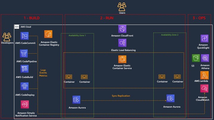
version: 0.2
env:
  variables:
    # Definining CloudFormation Teamplate and Ruleset as variables - part of the code repo
    CF_TEMPLATE: "cfn_template_file_example.yaml"
    CF_ORG_RULESET:  "cfn_guard_ruleset_example"
phases:
  install:
    commands:
      - apt-get update
      - apt-get install build-essential -y
      - apt-get install cargo -y
      - apt-get install git -y
  pre_build:
    commands:
      - echo "Setting up the environment for AWS CloudFormation Guard"
      - echo "More info https://github.com/aws-cloudformation/cloudformation-guard"
      - echo "Install Rust"
      - curl https://sh.rustup.rs -sSf | sh -s -- -y
  build:
    commands:
       - echo "Pull GA release from github"
       - echo "More info https://github.com/aws-cloudformation/cloudformation-guard/releases"
       - wget https://github.com/aws-cloudformation/cloudformation-guard/releases/download/1.0.0/cfn-guard-linux-1.0.0.tar.gz
       - echo "Extract cfn-guard"
       - tar xvf cfn-guard-linux-1.0.0.tar.gz .
  post_build:
    commands:
       - echo "Validate CloudFormation template with cfn-guard tool"
       - echo "More information https://github.com/aws-cloudformation/cloudformation-guard/blob/master/cfn-guard/README.md"
       - cfn-guard-linux/cfn-guard check --rule_set $CF_ORG_RULESET --template $CF_TEMPLATE --strict-checks
artifacts:
  files:
    - cfn_template_file_example.yaml
  name: guard_templates
  1. An example of a rule set file (cfn_guard_ruleset_example) for CloudFormation Guard. Modify the following code as per your requirements:
#CFN Guard rules set example

#List of multiple references
let allowed_azs = [us-east-1a,us-east-1b]
let allowed_ec2_instance_types = [t2.micro,t3.nano,t3.micro]
let allowed_security_groups = [sg-08bbcxxc21e9ba8e6,sg-07b8bx98795dcab2]

#EC2 Policies
AWS::EC2::Instance AvailabilityZone IN %allowed_azs
AWS::EC2::Instance ImageId == ami-0323c3dd2da7fb37d
AWS::EC2::Instance InstanceType IN %allowed_ec2_instance_types
AWS::EC2::Instance SecurityGroupIds == ["sg-07b8xxxsscab2"]
AWS::EC2::Instance SubnetId == subnet-0407a7casssse558

#EBS Policies
AWS::EC2::Volume AvailabilityZone == us-east-1a
AWS::EC2::Volume Encrypted == true
AWS::EC2::Volume Size == 50 |OR| AWS::EC2::Volume Size == 100
AWS::EC2::Volume VolumeType == gp2
  1. An example of a CloudFormation template file (.yaml). Modify the following code as per your requirements:
AWSTemplateFormatVersion: "2010-09-09"
Description: "EC2 instance with encrypted EBS volume for AWS CloudFormation Guard Testing"

Resources:

 EC2Instance:
    Type: AWS::EC2::Instance
    Properties:
      ImageId: 'ami-0323c3dd2da7fb37d'
      AvailabilityZone: 'us-east-1a'
      KeyName: "your-ssh-key"
      InstanceType: 't3.micro'
      SubnetId: 'subnet-0407a7xx68410e558'
      SecurityGroupIds:
        - 'sg-07b8b339xx95dcab2'
      Volumes:
         - 
          Device: '/dev/sdf'
          VolumeId: !Ref EBSVolume
      Tags:
       - Key: Name
         Value: cfn-guard-ec2

 EBSVolume:
   Type: AWS::EC2::Volume
   Properties:
     Size: 100
     AvailabilityZone: 'us-east-1a'
     Encrypted: true
     VolumeType: gp2
     Tags:
       - Key: Name
         Value: cfn-guard-ebs
   DeletionPolicy: Snapshot

Outputs:
  InstanceID:
    Description: The Instance ID
    Value: !Ref EC2Instance
  Volume:
    Description: The Volume ID
    Value: !Ref  EBSVolume
AWS CodeCommit

Optional CodeCommit Repository Structure

The following screenshot shows a potential CodeCommit repository structure.

Creating a CodeBuild project

Our CodeBuild project orchestrates around CloudFormation Guard and runs validation checks of our CloudFormation templates as a phase of the CI process.

  1. On the CodeBuild console, choose Build projects.
  2. Choose Create build projects.
  3. For Project name, enter your project name.
  4. For Description, enter a description.
AWS CodeBuild

Create CodeBuild Project

  1. For Source provider, choose AWS CodeCommit.
  2. For Repository, choose the CodeCommit repository you created in the previous step.
AWS CodeBuild

Define the source for your CodeBuild Project

To setup CodeBuild environment we will use managed image based on Ubuntu 18.04

  1. For Environment Image, select Managed image.
  2. For Operating system, choose Ubuntu.
  3. For Service role¸ select New service role.
  4. For Role name, enter your service role name.
CodeBuild Environment

Setup the environment, the OS image and other settings for the CodeBuild

  1. Leave the default settings for additional configuration, buildspec, batch configuration, artifacts, and logs.

You can also use CodeBuild with custom build environments to help you optimize billing and improve the build time.

Creating IAM roles and policies

Our CI/CD pipeline needs two AWS Identity and Access Management (IAM) roles to run properly: one role for CodePipeline to work with other resources and services, and one role for AWS CloudFormation to run the deployments that passed the validation check in the CodeBuild phase.

Creating permission policies

Create your permission policies first. The following code is the policy in JSON format for CodePipeline:

{
    "Version": "2012-10-17",
    "Statement": [
        {
            "Sid": "VisualEditor0",
            "Effect": "Allow",
            "Action": [
                "codecommit:UploadArchive",
                "codecommit:CancelUploadArchive",
                "codecommit:GetCommit",
                "codecommit:GetUploadArchiveStatus",
                "codecommit:GetBranch",
                "codestar-connections:UseConnection",
                "codebuild:BatchGetBuilds",
                "codedeploy:CreateDeployment",
                "codedeploy:GetApplicationRevision",
                "codedeploy:RegisterApplicationRevision",
                "codedeploy:GetDeploymentConfig",
                "codedeploy:GetDeployment",
                "codebuild:StartBuild",
                "codedeploy:GetApplication",
                "s3:*",
                "cloudformation:*",
                "ec2:*"
            ],
            "Resource": "*"
        },
        {
            "Sid": "VisualEditor1",
            "Effect": "Allow",
            "Action": "iam:PassRole",
            "Resource": "*",
            "Condition": {
                "StringEqualsIfExists": {
                    "iam:PassedToService": [
                        "cloudformation.amazonaws.com",
                        "ec2.amazonaws.com"
                    ]
                }
            }
        }
    ]
}

To create your policy for CodePipeline, run the following CLI command:

aws iam create-policy --policy-name CodePipeline-Cfn-Guard-Demo --policy-document file://CodePipelineServiceRolePolicy_example.json

Capture the policy ARN that you get in the output to use in the next steps.

The following code is the policy in JSON format for AWS CloudFormation:

{
    "Version": "2012-10-17",
    "Statement": [
        {
            "Sid": "VisualEditor0",
            "Effect": "Allow",
            "Action": "iam:CreateServiceLinkedRole",
            "Resource": "*",
            "Condition": {
                "StringEquals": {
                    "iam:AWSServiceName": [
                        "autoscaling.amazonaws.com",
                        "ec2scheduled.amazonaws.com",
                        "elasticloadbalancing.amazonaws.com"
                    ]
                }
            }
        },
        {
            "Sid": "VisualEditor1",
            "Effect": "Allow",
            "Action": [
                "s3:GetObjectAcl",
                "s3:GetObject",
                "cloudwatch:*",
                "ec2:*",
                "autoscaling:*",
                "s3:List*",
                "s3:HeadBucket"
            ],
            "Resource": "*"
        }
    ]
}

Create the policy for AWS CloudFormation by running the following CLI command:

aws iam create-policy --policy-name CloudFormation-Cfn-Guard-Demo --policy-document file://CloudFormationRolePolicy_example.json

Capture the policy ARN that you get in the output to use in the next steps.

Creating roles and trust policies

The following code is the trust policy for CodePipeline in JSON format:

{
  "Version": "2012-10-17",
  "Statement": [
    {
      "Effect": "Allow",
      "Principal": {
        "Service": "codepipeline.amazonaws.com"
      },
      "Action": "sts:AssumeRole"
    }
  ]
}

Create your role for CodePipeline with the following CLI command:

aws iam create-role --role-name CodePipeline-Cfn-Guard-Demo-Role --assume-role-policy-document file://RoleTrustPolicy_CodePipeline.json

Capture the role name for the next step.

The following code is the trust policy for AWS CloudFormation in JSON format:

{
  "Version": "2012-10-17",
  "Statement": [
    {
      "Sid": "",
      "Effect": "Allow",
      "Principal": {
        "Service": "cloudformation.amazonaws.com"
      },
      "Action": "sts:AssumeRole"
    }
  ]
}

Create your role for AWS CloudFormation with the following CLI command:

aws iam create-role --role-name CF-Cfn-Guard-Demo-Role --assume-role-policy-document file://RoleTrustPolicy_CloudFormation.json

Capture the role name for the next step.


Finally, attach the permissions policies created in the previous step to the IAM roles you created:

aws iam attach-role-policy --role-name CodePipeline-Cfn-Guard-Demo-Role  --policy-arn "arn:aws:iam::<AWS Account Id >:policy/CodePipeline-Cfn-Guard-Demo"

aws iam attach-role-policy --role-name CF-Cfn-Guard-Demo-Role  --policy-arn "arn:aws:iam::<AWS Account Id>:policy/CloudFormation-Cfn-Guard-Demo"

Creating a pipeline

We can now create our pipeline to assemble all the components into one managed, continuous mechanism.

  1. On the CodePipeline console, choose Pipelines.
  2. Choose Create new pipeline.
  3. For Pipeline name, enter a name.
  4. For Service role, select Existing service role.
  5. For Role ARN, choose the service role you created in the previous step.
  6. Choose Next.
CodePipeline Setup

Setting Up CodePipeline environment

  1. In the Source section, for Source provider, choose AWS CodeCommit.
  2. For Repository name¸ enter your repository name.
  3. For Branch name, choose master.
  4. For Change detection options, select Amazon CloudWatch Events.
  5. Choose Next.
AWS CodePipeline Source

Adding CodeCommit to CodePipeline

  1. In the Build section, for Build provider, choose AWS CodeBuild.
  2. For Project name, choose the CodeBuild project you created.
  3. For Build type, select Single build.
  4. Choose Next.
CodePipeline Build Stage

Adding Build Project to Pipeline Stage

Now we will create a deploy stage in our CodePipeline to deploy CloudFormation templates that passed the CloudFormation Guard inspection in the CI stage.

  1. In the Deploy section, for Deploy provider, choose AWS CloudFormation.
  2. For Action mode¸ choose Create or update stack.
  3. For Stack name, choose any stack name.
  4. For Artifact name, choose BuildArtifact.
  5. For File name, enter the CloudFormation template name in your CodeCommit repository (In case of our demo it is cfn_template_file_example.yaml).
  6. For Role name, choose the role you created earlier for CloudFormation.
CodePipeline - Deploy Stage

Adding deploy stage to CodePipeline

22. In the next step review your selections for the pipeline to be created. The stages and action providers in each stage are shown in the order that they will be created. Click Create pipeline. Our CodePipeline is ready.

Validating the CI/CD pipeline operation

Our CodePipeline has two basic flows and outcomes. If the CloudFormation template complies with our CloudFormation Guard rule set file, the resources in the template deploy successfully (in our use case, we deploy an EC2 instance with an encrypted EBS volume).

CloudFormation Deployed

CloudFormation Console

If our CloudFormation template doesn’t comply with the policies specified in our CloudFormation Guard rule set file, our CodePipeline stops at the CodeBuild step and you see an error in the build job log indicating the resources that are non-compliant:

[EBSVolume] failed because [Encrypted] is [false] and the permitted value is [true]
[EC2Instance] failed because [t3.2xlarge] is not in [t2.micro,t3.nano,t3.micro] for [InstanceType]
Number of failures: 2

Note: To demonstrate the above functionality I changed my CloudFormation template to use unencrypted EBS volume and switched the EC2 instance type to t3.2xlarge which do not adhere to the rules that we specified in the Guard rule set file

Cleaning up

To avoid incurring future charges, delete the resources that we have created during the walkthrough:

  • CloudFormation stack resources that were deployed by the CodePipeline
  • CodePipeline that we have created
  • CodeBuild project
  • CodeCommit repository

Conclusion

In this post, we covered how to integrate CloudFormation Guard into CodePipeline and fully automate pre-deployment compliance checks of your CloudFormation templates. This allows your teams to have an end-to-end automated CI/CD pipeline with minimal operational overhead and stay compliant with your organizational infrastructure policies.

Complete CI/CD with AWS CodeCommit, AWS CodeBuild, AWS CodeDeploy, and AWS CodePipeline

Post Syndicated from Nitin Verma original https://aws.amazon.com/blogs/devops/complete-ci-cd-with-aws-codecommit-aws-codebuild-aws-codedeploy-and-aws-codepipeline/

Many organizations have been shifting to DevOps practices, which is the combination of cultural philosophies, practices, and tools that increases your organization’s ability to deliver applications and services at high velocity; for example, evolving and improving products at a faster pace than organizations using traditional software development and infrastructure management processes.

DevOps-Feedback-Flow

An integral part of DevOps is adopting the culture of continuous integration and continuous delivery/deployment (CI/CD), where a commit or change to code passes through various automated stage gates, all the way from building and testing to deploying applications, from development to production environments.

This post uses the AWS suite of CI/CD services to compile, build, and install a version-controlled Java application onto a set of Amazon Elastic Compute Cloud (Amazon EC2) Linux instances via a fully automated and secure pipeline. The goal is to promote a code commit or change to pass through various automated stage gates all the way from development to production environments, across AWS accounts.

AWS services

This solution uses the following AWS services:

  • AWS CodeCommit – A fully-managed source control service that hosts secure Git-based repositories. CodeCommit makes it easy for teams to collaborate on code in a secure and highly scalable ecosystem. This solution uses CodeCommit to create a repository to store the application and deployment codes.
  • AWS CodeBuild – A fully managed continuous integration service that compiles source code, runs tests, and produces software packages that are ready to deploy, on a dynamically created build server. This solution uses CodeBuild to build and test the code, which we deploy later.
  • AWS CodeDeploy – A fully managed deployment service that automates software deployments to a variety of compute services such as Amazon EC2, AWS Fargate, AWS Lambda, and your on-premises servers. This solution uses CodeDeploy to deploy the code or application onto a set of EC2 instances running CodeDeploy agents.
  • AWS CodePipeline – A fully managed continuous delivery service that helps you automate your release pipelines for fast and reliable application and infrastructure updates. This solution uses CodePipeline to create an end-to-end pipeline that fetches the application code from CodeCommit, builds and tests using CodeBuild, and finally deploys using CodeDeploy.
  • AWS CloudWatch Events – An AWS CloudWatch Events rule is created to trigger the CodePipeline on a Git commit to the CodeCommit repository.
  • Amazon Simple Storage Service (Amazon S3) – An object storage service that offers industry-leading scalability, data availability, security, and performance. This solution uses an S3 bucket to store the build and deployment artifacts created during the pipeline run.
  • AWS Key Management Service (AWS KMS) – AWS KMS makes it easy for you to create and manage cryptographic keys and control their use across a wide range of AWS services and in your applications. This solution uses AWS KMS to make sure that the build and deployment artifacts stored on the S3 bucket are encrypted at rest.

Overview of solution

This solution uses two separate AWS accounts: a dev account (111111111111) and a prod account (222222222222) in Region us-east-1.

We use the dev account to deploy and set up the CI/CD pipeline, along with the source code repo. It also builds and tests the code locally and performs a test deploy.

The prod account is any other account where the application is required to be deployed from the pipeline in the dev account.

In summary, the solution has the following workflow:

  • A change or commit to the code in the CodeCommit application repository triggers CodePipeline with the help of a CloudWatch event.
  • The pipeline downloads the code from the CodeCommit repository, initiates the Build and Test action using CodeBuild, and securely saves the built artifact on the S3 bucket.
  • If the preceding step is successful, the pipeline triggers the Deploy in Dev action using CodeDeploy and deploys the app in dev account.
  • If successful, the pipeline triggers the Deploy in Prod action using CodeDeploy and deploys the app in the prod account.

The following diagram illustrates the workflow:

cicd-overall-flow


Failsafe deployments

This example of CodeDeploy uses the IN_PLACE type of deployment. However, to minimize the downtime, CodeDeploy inherently supports multiple deployment strategies. This example makes use of following features: rolling deployments and automatic rollback.

CodeDeploy provides the following three predefined deployment configurations, to minimize the impact during application upgrades:

  • CodeDeployDefault.OneAtATime – Deploys the application revision to only one instance at a time
  • CodeDeployDefault.HalfAtATime – Deploys to up to half of the instances at a time (with fractions rounded down)
  • CodeDeployDefault.AllAtOnce – Attempts to deploy an application revision to as many instances as possible at once

For OneAtATime and HalfAtATime, CodeDeploy monitors and evaluates instance health during the deployment and only proceeds to the next instance or next half if the previous deployment is healthy. For more information, see Working with deployment configurations in CodeDeploy.

You can also configure a deployment group or deployment to automatically roll back when a deployment fails or when a monitoring threshold you specify is met. In this case, the last known good version of an application revision is automatically redeployed after a failure with the new application version.

How CodePipeline in the dev account deploys apps in the prod account

In this post, the deployment pipeline using CodePipeline is set up in the dev account, but it has permissions to deploy the application in the prod account. We create a special cross-account role in the prod account, which has the following:

  • Permission to use fetch artifacts (app) rom Amazon S3 and deploy it locally in the account using CodeDeploy
  • Trust with the dev account where the pipeline runs

CodePipeline in the dev account assumes this cross-account role in the prod account to deploy the app.

Do I need multiple accounts?
If you answer “yes” to any of the following questions you should consider creating more AWS accounts:

  • Does your business require administrative isolation between workloads? Administrative isolation by account is the most straightforward way to grant independent administrative groups different levels of administrative control over AWS resources based on workload, development lifecycle, business unit (BU), or data sensitivity.
  • Does your business require limited visibility and discoverability of workloads? Accounts provide a natural boundary for visibility and discoverability. Workloads cannot be accessed or viewed unless an administrator of the account enables access to users managed in another account.
  • Does your business require isolation to minimize blast radius? Separate accounts help define boundaries and provide natural blast-radius isolation to limit the impact of a critical event such as a security breach, an unavailable AWS Region or Availability Zone, account suspensions, and so on.
  • Does your business require a particular workload to operate within AWS service limits without impacting the limits of another workload? You can use AWS account service limits to impose restrictions on a business unit, development team, or project. For example, if you create an AWS account for a project group, you can limit the number of Amazon Elastic Compute Cloud (Amazon EC2) or high performance computing (HPC) instances that can be launched by the account.
  • Does your business require strong isolation of recovery or auditing data? If regulatory requirements require you to control access and visibility to auditing data, you can isolate the data in an account separate from the one where you run your workloads (for example, by writing AWS CloudTrail logs to a different account).

Prerequisites

For this walkthrough, you should complete the following prerequisites:

  1. Have access to at least two AWS accounts. For this post, the dev and prod accounts are in us-east-1. You can search and replace the Region and account IDs in all the steps and sample AWS Identity and Access Management (IAM) policies in this post.
  2. Ensure you have EC2 Linux instances with the CodeDeploy agent installed in all the accounts or VPCs where the sample Java application is to be installed (dev and prod accounts).
    • To manually create EC2 instances with CodeDeploy agent, refer Create an Amazon EC2 instance for CodeDeploy (AWS CLI or Amazon EC2 console). Keep in mind the following:
      • CodeDeploy uses EC2 instance tags to identify instances to use to deploy the application, so it’s important to set tags appropriately. For this post, we use the tag name Application with the value MyWebApp to identify instances where the sample app is installed.
      • Make sure to use an EC2 instance profile (AWS Service Role for EC2 instance) with permissions to read the S3 bucket containing artifacts built by CodeBuild. Refer to the IAM role cicd_ec2_instance_profile in the table Roles-1 below for the set of permissions required. You must update this role later with the actual KMS key and S3 bucket name created as part of the deployment process.
    • To create EC2 Linux instances via AWS Cloudformation, download and launch the AWS CloudFormation template from the GitHub repo: cicd-ec2-instance-with-codedeploy.json
      • This deploys an EC2 instance with AWS CodeDeploy agent.
      • Inputs required:
        • AMI : Enter name of the Linux AMI in your region. (This template has been tested with latest Amazon Linux 2 AMI)
        • Ec2SshKeyPairName: Name of an existing SSH KeyPair
        • Ec2IamInstanceProfile: Name of an existing EC2 instance profile. Note: Use the permissions in the template cicd_ec2_instance_profile_policy.json to create the policy for this EC2 Instance Profile role. You must update this role later with the actual KMS key and S3 bucket name created as part of the deployment process.
        • Update the EC2 instance Tags per your need.
  3. Ensure required IAM permissions. Have an IAM user with an IAM Group or Role that has the following access levels or permissions:

    AWS Service / Components  Access Level Accounts Comments
    AWS CodeCommit Full (admin) Dev Use AWS managed policy AWSCodeCommitFullAccess.
    AWS CodePipeline Full (admin) Dev Use AWS managed policy AWSCodePipelineFullAccess.
    AWS CodeBuild Full (admin) Dev Use AWS managed policy AWSCodeBuildAdminAccess.
    AWS CodeDeploy Full (admin) All

    Use AWS managed policy

    AWSCodeDeployFullAccess.

    Create S3 bucket and bucket policies Full (admin) Dev IAM policies can be restricted to specific bucket.
    Create KMS key and policies Full (admin) Dev IAM policies can be restricted to specific KMS key.
    AWS CloudFormation Full (admin) Dev

    Use AWS managed policy

    AWSCloudFormationFullAccess.

    Create and pass IAM roles Full (admin) All Ability to create IAM roles and policies can be restricted to specific IAM roles or actions. Also, an admin team with IAM privileges could create all the required roles. Refer to the IAM table Roles-1 below.
    AWS Management Console and AWS CLI As per IAM User permissions All To access suite of Code services.


  4. Create Git credentials for CodeCommit in the pipeline account (dev account). AWS allows you to either use Git credentials or associate SSH public keys with your IAM user. For this post, use Git credentials associated with your IAM user (created in the previous step). For instructions on creating a Git user, see Create Git credentials for HTTPS connections to CodeCommit. Download and save the Git credentials to use later for deploying the application.
  5. Create all AWS IAM roles as per the following tables (Roles-1). Make sure to update the following references in all the given IAM roles and policies:
    • Replace the sample dev account (111111111111) and prod account (222222222222) with actual account IDs
    • Replace the S3 bucket mywebapp-codepipeline-bucket-us-east-1-111111111111 with your preferred bucket name.
    • Replace the KMS key ID key/82215457-e360-47fc-87dc-a04681c91ce1 with your KMS key ID.

Table: Roles-1

Service IAM Role Type Account IAM Role Name (used for this post) IAM Role Policy (required for this post) IAM Role Permissions
AWS CodePipeline Service role Dev (111111111111)

cicd_codepipeline_service_role

Select Another AWS Account and use this account as the account ID to create the role.

Later update the trust as follows:
“Principal”: {“Service”: “codepipeline.amazonaws.com”},

Use the permissions in the template cicd_codepipeline_service_policy.json to create the policy for this role. This CodePipeline service role has appropriate permissions to the following services in a local account:

  • Manage CodeCommit repos
  • Initiate build via CodeBuild
  • Create deployments via CodeDeploy
  • Assume cross-account CodeDeploy role in prod account to deploy the application
AWS CodePipeline IAM role Dev (111111111111)

cicd_codepipeline_trigger_cwe_role

Select Another AWS Account and use this account as the account ID to create the role.

Later update the trust as follows:
“Principal”: {“Service”: “events.amazonaws.com”},

Use the permissions in the template cicd_codepipeline_trigger_cwe_policy.json to create the policy for this role. CodePipeline uses this role to set a CloudWatch event to trigger the pipeline when there is a change or commit made to the code repository.
AWS CodePipeline IAM role Prod (222222222222)

cicd_codepipeline_cross_ac_role

Choose Another AWS Account and use the dev account as the trusted account ID to create the role.

Use the permissions in the template cicd_codepipeline_cross_ac_policy.json to create the policy for this role. This role is created in the prod account and has permissions to use CodeDeploy and fetch from Amazon S3. The role is assumed by CodePipeline from the dev account to deploy the app in the prod account. Make sure to set up trust with the dev account for this IAM role on the Trust relationships tab.
AWS CodeBuild Service role Dev (111111111111)

cicd_codebuild_service_role

Choose CodeBuild as the use case to create the role.

Use the permissions in the template cicd_codebuild_service_policy.json to create the policy for this role. This CodeBuild service role has appropriate permissions to:

  • The S3 bucket to store artefacts
  • Stream logs to CloudWatch Logs
  • Pull code from CodeCommit
  • Get the SSM parameter for CodeBuild
  • Miscellaneous Amazon EC2 permissions
AWS CodeDeploy Service role Dev (111111111111) and Prod (222222222222)

cicd_codedeploy_service_role

Choose CodeDeploy as the use case to create the role.

Use the built-in AWS managed policy AWSCodeDeployRole for this role. This CodeDeploy service role has appropriate permissions to:

  • Miscellaneous Amazon EC2 Auto Scaling
  • Miscellaneous Amazon EC2
  • Publish Amazon SNS topic
  • AWS CloudWatch metrics
  • Elastic Load Balancing
EC2 Instance Service role for EC2 instance profile Dev (111111111111) and Prod (222222222222)

cicd_ec2_instance_profile

Choose EC2 as the use case to create the role.

Use the permissions in the template cicd_ec2_instance_profile_policy.json to create the policy for this role.

This is set as the EC2 instance profile for the EC2 instances where the app is deployed. It has appropriate permissions to fetch artefacts from Amazon S3 and decrypt contents using the KMS key.


You must update this role later with the actual KMS key and S3 bucket name created as part of the deployment process.


Setting up the prod account

To set up the prod account, complete the following steps:

  1. Download and launch the AWS CloudFormation template from the GitHub repo: cicd-codedeploy-prod.json
    • This deploys the CodeDeploy app and deployment group.
    • Make sure that you already have a set of EC2 Linux instances with the CodeDeploy agent installed in all the accounts where the sample Java application is to be installed (dev and prod accounts). If not, refer back to the Prerequisites section.
  2. Update the existing EC2 IAM instance profile (cicd_ec2_instance_profile):
    • Replace the S3 bucket name mywebapp-codepipeline-bucket-us-east-1-111111111111 with your S3 bucket name (the one used for the CodePipelineArtifactS3Bucket variable when you launched the CloudFormation template in the dev account).
    • Replace the KMS key ARN arn:aws:kms:us-east-1:111111111111:key/82215457-e360-47fc-87dc-a04681c91ce1 with your KMS key ARN (the one created as part of the CloudFormation template launch in the dev account).

Setting up the dev account

To set up your dev account, complete the following steps:

  1. Download and launch the CloudFormation template from the GitHub repo: cicd-aws-code-suite-dev.json
    The stack deploys the following services in the dev account:

    • CodeCommit repository
    • CodePipeline
    • CodeBuild environment
    • CodeDeploy app and deployment group
    • CloudWatch event rule
    • KMS key (used to encrypt the S3 bucket)
    • S3 bucket and bucket policy
  2. Use following values as inputs to the CloudFormation template. You should have created all the existing resources and roles beforehand as part of the prerequisites.

    Key Example Value Comments
    CodeCommitWebAppRepo MyWebAppRepo Name of the new CodeCommit repository for your web app.
    CodeCommitMainBranchName master Main branch name on your CodeCommit repository. Default is master (which is pushed to the prod environment).
    CodeBuildProjectName MyCBWebAppProject Name of the new CodeBuild environment.
    CodeBuildServiceRole arn:aws:iam::111111111111:role/cicd_codebuild_service_role ARN of an existing IAM service role to be associated with CodeBuild to build web app code.
    CodeDeployApp MyCDWebApp Name of the new CodeDeploy app to be created for your web app. We assume that the CodeDeploy app name is the same in all accounts where deployment needs to occur (in this case, the prod account).
    CodeDeployGroupDev MyCICD-Deployment-Group-Dev Name of the new CodeDeploy deployment group to be created in the dev account.
    CodeDeployGroupProd MyCICD-Deployment-Group-Prod Name of the existing CodeDeploy deployment group in prod account. Created as part of the prod account setup.

    CodeDeployGroupTagKey


    Application Name of the tag key that CodeDeploy uses to identify the existing EC2 fleet for the deployment group to use.

    CodeDeployGroupTagValue


    MyWebApp Value of the tag that CodeDeploy uses to identify the existing EC2 fleet for the deployment group to use.
    CodeDeployConfigName CodeDeployDefault.OneAtATime

    Desired Code Deploy config name. Valid options are:

    CodeDeployDefault.OneAtATime

    CodeDeployDefault.HalfAtATime

    CodeDeployDefault.AllAtOnce

    For more information, see Deployment configurations on an EC2/on-premises compute platform.

    CodeDeployServiceRole arn:aws:iam::111111111111:role/cicd_codedeploy_service_role

    ARN of an existing IAM service role to be associated with CodeDeploy to deploy web app.


    CodePipelineName MyWebAppPipeline Name of the new CodePipeline to be created for your web app.
    CodePipelineArtifactS3Bucket mywebapp-codepipeline-bucket-us-east-1-111111111111 Name of the new S3 bucket to be created where artifacts for the pipeline are stored for this web app.
    CodePipelineServiceRole arn:aws:iam::111111111111:role/cicd_codepipeline_service_role ARN of an existing IAM service role to be associated with CodePipeline to deploy web app.
    CodePipelineCWEventTriggerRole arn:aws:iam::111111111111:role/cicd_codepipeline_trigger_cwe_role ARN of an existing IAM role used to trigger the pipeline you named earlier upon a code push to the CodeCommit repository.
    CodeDeployRoleXAProd arn:aws:iam::222222222222:role/cicd_codepipeline_cross_ac_role ARN of an existing IAM role in the cross-account for CodePipeline to assume to deploy the app.

    It should take 5–10 minutes for the CloudFormation stack to complete. When the stack is complete, you can see that CodePipeline has built the pipeline (MyWebAppPipeline) with the CodeCommit repository and CodeBuild environment, along with actions for CodeDeploy in local (dev) and cross-account (prod). CodePipeline should be in a failed state because your CodeCommit repository is empty initially.

  3. Update the existing Amazon EC2 IAM instance profile (cicd_ec2_instance_profile):
    • Replace the S3 bucket name mywebapp-codepipeline-bucket-us-east-1-111111111111 with your S3 bucket name (the one used for the CodePipelineArtifactS3Bucket parameter when launching the CloudFormation template in the dev account).
    • Replace the KMS key ARN arn:aws:kms:us-east-1:111111111111:key/82215457-e360-47fc-87dc-a04681c91ce1 with your KMS key ARN (the one created as part of the CloudFormation template launch in the dev account).

Deploying the application

You’re now ready to deploy the application via your desktop or PC.

  1. Assuming you have the required HTTPS Git credentials for CodeCommit as part of the prerequisites, clone the CodeCommit repo that was created earlier as part of the dev account setup. Obtain the name of the CodeCommit repo to clone, from the CodeCommit console. Enter the Git user name and password when prompted. For example:
    $ git clone https://git-codecommit.us-east-1.amazonaws.com/v1/repos/MyWebAppRepo my-web-app-repo
    Cloning into 'my-web-app-repo'...
    Username for 'https://git-codecommit.us-east-1.amazonaws.com/v1/repos/MyWebAppRepo': xxxx
    Password for 'https://[email protected]/v1/repos/MyWebAppRepo': xxxx

  2. Download the MyWebAppRepo.zip file containing a sample Java application, CodeBuild configuration to build the app, and CodeDeploy config file to deploy the app.
  3. Copy and unzip the file into the my-web-app-repo Git repository folder created earlier.
  4. Assuming this is the sample app to be deployed, commit these changes to the Git repo. For example:
    $ cd my-web-app-repo 
    $ git add -A 
    $ git commit -m "initial commit" 
    $ git push

For more information, see Tutorial: Create a simple pipeline (CodeCommit repository).

After you commit the code, the CodePipeline will be triggered and all the stages and your application should be built, tested, and deployed all the way to the production environment!

The following screenshot shows the entire pipeline and its latest run:


Troubleshooting

To troubleshoot any service-related issues, see the following:

Cleaning up

To avoid incurring future charges or to remove any unwanted resources, delete the following:

  • EC2 instance used to deploy the application
  • CloudFormation template to remove all AWS resources created through this post
  •  IAM users or roles

Conclusion

Using this solution, you can easily set up and manage an entire CI/CD pipeline in AWS accounts using the native AWS suite of CI/CD services, where a commit or change to code passes through various automated stage gates all the way from building and testing to deploying applications, from development to production environments.

FAQs

In this section, we answer some frequently asked questions:

  1. Can I expand this deployment to more than two accounts?
    • Yes. You can deploy a pipeline in a tooling account and use dev, non-prod, and prod accounts to deploy code on EC2 instances via CodeDeploy. Changes are required to the templates and policies accordingly.
  2. Can I ensure the application isn’t automatically deployed in the prod account via CodePipeline and needs manual approval?
  3. Can I use a CodeDeploy group with an Auto Scaling group?
    • Yes. Minor changes required to the CodeDeploy group creation process. Refer to the following Solution Variations section for more information.
  4. Can I use this pattern for EC2 Windows instances?

Solution variations

In this section, we provide a few variations to our solution:

Author bio

author-pic

 Nitin Verma

Nitin is currently a Sr. Cloud Architect in the AWS Managed Services(AMS). He has many years of experience with DevOps-related tools and technologies. Speak to your AWS Managed Services representative to deploy this solution in AMS!


Why Deployment Requirements are Important When Making Architectural Choices

Post Syndicated from Yusuf Mayet original https://aws.amazon.com/blogs/architecture/why-deployment-requirements-are-important-when-making-architectural-choices/

Introduction

Too often, architects fall into the trap of thinking the architecture of an application is restricted to just the runtime part of the architecture. By doing this we focus on only a single customer (such as the application’s users and how they interact with the system) and we forget about other important customers like developers and DevOps teams. This means that requirements regarding deployment ease, deployment frequency, and observability are delegated to the back burner during design time and tacked on after the runtime architecture is built. This leads to increased costs and reduced ability to innovate.

In this post, I discuss the importance of key non-functional requirements, and how they can and should influence the target architecture at design time.

Architectural patterns

When building and designing new applications, we usually start by looking at the functional requirements, which will define the functionality and objective of the application. These are all the things that the users of the application expect, such as shopping online, searching for products, and ordering. We also consider aspects such as usability to ensure a great user experience (UX).

We then consider the non-functional requirements, the so-called “ilities,” which typically include requirements regarding scalability, availability, latency, etc. These are constraints around the functional requirements, like response times for placing orders or searching for products, which will define the expected latency of the system.

These requirements—both functional and non-functional together—dictate the architectural pattern we choose to build the application. These patterns include Multi-tierevent-driven architecturemicroservices, and others, and each one has benefits and limitations. For example, a microservices architecture allows for a system where services can be deployed and scaled independently, but this also introduces complexity around service discovery.

Aligning the architecture to technical users’ requirements

Amazon is a customer-obsessed organization, so it’s important for us to first identify who the main customers are at each point so that we can meet their needs. The customers of the functional requirements are the application users, so we need to ensure the application meets their needs. For the most part, we will ensure that the desired product features are supported by the architecture.

But who are the users of the architecture? Not the applications’ users—they don’t care if it’s monolithic or microservices based, as long as they can shop and search for products. The main customers of the architecture are the technical teams: the developers, architects, and operations teams that build and support the application. We need to work backwards from the customers’ needs (in this case the technical team), and make sure that the architecture meets their requirements. We have therefore identified three non-functional requirements that are important to consider when designing an architecture that can equally meet the needs of the technical users:

  1. Deployability: Flow and agility to consistently deploy new features
  2. Observability: feedback about the state of the application
  3. Disposability: throwing away resources and provision new ones quickly

Together these form part of the Developer Experience (DX), which is focused on providing developers with APIs, documentation, and other technologies to make it easy to understand and use. This will ensure that we design for Day 2 operations in mind.

Deployability: Flow

There are many reasons that organizations embark on digital transformation journeys, which usually involve moving to the cloud and adopting DevOps. According to Stephen Orban, GM of AWS Data Exchange, in his book Ahead in the Cloud, faster product development is often a key motivator, meaning the most important non-functional requirement is achieving flow, the speed at which you can consistently deploy new applications, respond to competitors, and test and roll out new features. As well, the architecture needs to be designed upfront to support deployability. If the architectural pattern is a monolithic application, this will hamper the developers’ ability to quickly roll out new features to production. So we need to choose and design the architecture to support easy and automated deployments. Results from years of research prove that leaders use DevOps to achieve high levels of throughput:

Graphic - Using DevOps to achieve high levels of throughput

Decisions on the pace and frequency of deployments will dictate whether to use rolling, blue/green, or canary deployment methodologies. This will then inform the architectural pattern chosen for the application.

Using AWS, in order to achieve flow of deployability, we will use services such as AWS CodePipelineAWS CodeBuildAWS CodeDeploy and AWS CodeStar.

Observability: feedback

Once you have achieved a rapid and repeatable flow of features into production, you need a constant feedback loop of logs and metrics in order to detect and avoid problems. Observability is a property of the architecture that will allow us to better understand the application across the delivery pipeline and into production. This requires that we design the architecture to ensure that health reports are generated to analyze and spot trends. This includes error rates and stats from each stage of the development process, how many commits were made, build duration, and frequency of deployments. This not only allows us to measure code characteristics such as test coverage, but also developer productivity.

On AWS, we can leverage Amazon CloudWatch to gather and search through logs and metrics, AWS X-Ray for tracing, and Amazon QuickSight as an analytics tool to measure CI/CD metrics.

Disposability: automation

In his book, Cloud Strategy: A Decision-based Approach to a Successful Cloud Journey, Gregor Hohpe, Enterprise Strategist at AWS, notes that cloud and automation add a new “-ility”: disposability, which is the ability to set up and dispose of new servers in an automated and pain-free manner. Having immutable, disposable infrastructure greatly enhances your ability to achieve high levels of deployability and flow, especially when used in a CI/CD pipeline, which can create new resources and kill off the old ones.

At AWS, we can achieve disposability with serverless using AWS Lambda, or with containers running on Amazon Elastic Container Service (ECS) or Amazon Elastic Kubernetes Service (EKS), or using AWS Auto Scaling with Amazon Elastic Compute Cloud (EC2).

Three different views of the architecture

Once we have designed an architecture that caters for deployability, observability, and disposability, it exposes three lenses across which we can view the architecture:

3 views of the architecture

  1. Build lens: the focus of this part of the architecture is on achieving deployability, with the objective to give the developers an easy-to-use, automated platform that builds, tests, and pushes their code into the different environments, in a repeatable way. Developers can push code changes more reliably and frequently, and the operations team can see greater stability because environments have standard configurations and rollback procedures are automated
  2. Runtime lens: the focus is on the users of the application and on maximizing their experience by making the application responsive and highly available.
  3. Operate lens: the focus is on achieving observability for the DevOps teams, allowing them to have complete visibility into each part of the architecture.

Summary

When building and designing new applications, the functional requirements (such as UX) are usually the primary drivers for choosing and defining the architecture to support those requirements. In this post I have discussed how DX characteristics like deployability, observability, and disposability are not just operational concerns that get tacked on after the architecture is chosen. Rather, they should be as important as the functional requirements when choosing the architectural pattern. This ensures that the architecture can support the needs of both the developers and users, increasing quality and our ability to innovate.