Tag Archives: Amazon ECR

Best Practices to help secure your container image build pipeline by using AWS Signer

Post Syndicated from Jorge Castillo original https://aws.amazon.com/blogs/security/best-practices-to-help-secure-your-container-image-build-pipeline-by-using-aws-signer/

AWS Signer is a fully managed code-signing service to help ensure the trust and integrity of your code. It helps you verify that the code comes from a trusted source and that an unauthorized party has not accessed it. AWS Signer manages code signing certificates and public and private keys, which can reduce the overhead of your public key infrastructure (PKI) management. It also provides a set of features to simplify lifecycle management of your keys and certificates so that you can focus on signing and verifying your code.

In June 2023, AWS announced Container Image Signing with AWS Signer and Amazon EKS, a new capability that gives you native AWS support for signing and verifying container images stored in Amazon Elastic Container Registry (Amazon ECR).

Containers and AWS Lambda functions are popular serverless compute solutions for applications built on the cloud. By using AWS Signer, you can verify that the software running in these workloads originates from a trusted source.

In this blog post, you will learn about the benefits of code signing for software security, governance, and compliance needs. Flexible continuous integration and continuous delivery (CI/CD) integration, management of signing identities, and native integration with other AWS services can help you simplify code security through automation.

Background

Code signing is an important part of the software supply chain. It helps ensure that the code is unaltered and comes from an approved source.

To automate software development workflows, organizations often implement a CI/CD pipeline to push, test, and deploy code effectively. You can integrate code signing into the workflow to help prevent untrusted code from being deployed, as shown in Figure 1. Code signing in the pipeline can provide you with different types of information, depending on how you decide to use the functionality. For example, you can integrate code signing into the build stage to attest that the code was scanned for vulnerabilities, had its software bill of materials (SBOM) approved internally, and underwent unit and integration testing. You can also use code signing to verify who has pushed or published the code, such as a developer, team, or organization. You can verify each of these steps separately by including multiple signing stages in the pipeline. For more information on the value provided by container image signing, see Cryptographic Signing for Containers.
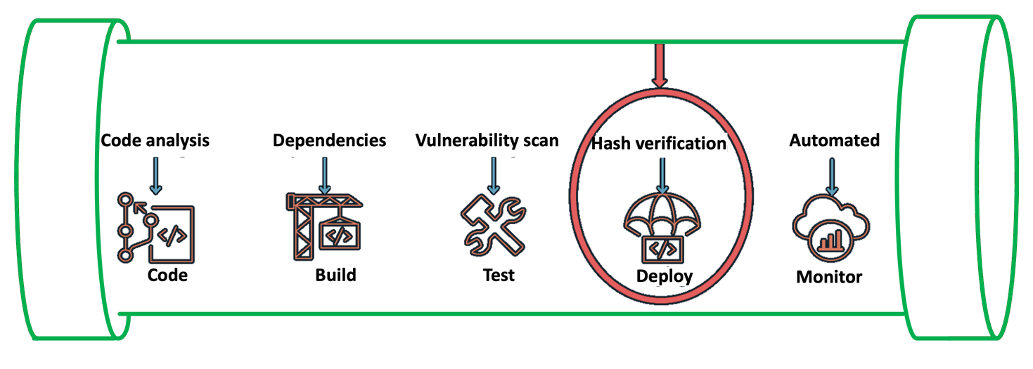
Figure 1: Security IN the pipeline

Figure 1: Security IN the pipeline

In the following section, we will walk you through a simple implementation of image signing and its verification for Amazon Elastic Kubernetes Service (Amazon EKS) deployment. The signature attests that the container image went through the pipeline and came from a trusted source. You can use this process in more complex scenarios by adding multiple AWS CodeBuild code signing stages that make use of various AWS Signer signing profiles.

Services and tools

In this section, we discuss the various AWS services and third-party tools that you need for this solution.

CI/CD services

For the CI/CD pipeline, you will use the following AWS services:

  • AWS CodePipeline — a fully managed continuous delivery service that you can use to automate your release pipelines for fast and reliable application and infrastructure updates.
  • AWS CodeCommit — a fully managed source control service that hosts secure Git-based repositories.
  • AWS Signer — a fully managed code-signing service that you can use to help ensure the trust and integrity of your code.
  • AWS CodeBuild — A fully managed continuous integration service that compiles source code, runs tests, and produces software packages that are ready to deploy.

Container services

You will use the following AWS services for containers for this walkthrough:

  • Amazon EKS — a managed Kubernetes service to run Kubernetes in the AWS Cloud and on-premises data centers.
  • Amazon ECR — a fully managed container registry for high-performance hosting, so that you can reliably deploy application images and artifacts anywhere.

Verification tools

The following are publicly available sign verification tools that we integrated into the pipeline for this post, but you could integrate other tools that meet your specific requirements.

  • Notation — A publicly available Notary project within the Cloud Native Computing Foundation (CNCF). With contributions from AWS and others, Notary is an open standard and client implementation that allows for vendor-specific plugins for key management and other integrations. AWS Signer manages signing keys, key rotation, and PKI management for you, and is integrated with Notation through a curated plugin that provides a simple client-based workflow.
  • Kyverno — A publicly available policy engine that is designed for Kubernetes.

Solution overview
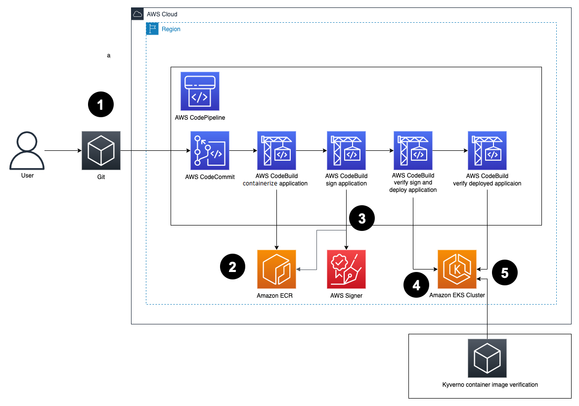
Figure 2: Solution architecture

Figure 2: Solution architecture

Here’s how the solution works, as shown in Figure 2:

  1. Developers push Dockerfiles and application code to CodeCommit. Each push to CodeCommit starts a pipeline hosted on CodePipeline.
  2. CodeBuild packages the build, containerizes the application, and stores the image in the ECR registry.
  3. CodeBuild retrieves a specific version of the image that was previously pushed to Amazon ECR. AWS Signer and Notation sign the image by using the signing profile established previously, as shown in more detail in Figure 3.
    Figure 3: Signing images described

    Figure 3: Signing images described

  4. AWS Signer and Notation verify the signed image version and then deploy it to an Amazon EKS cluster.

    If the image has not previously been signed correctly, the CodeBuild log displays an output similar to the following:

    Error: signature verification failed: no signature is associated with "<AWS_ACCOUNT_ID>.dkr.ecr.<AWS_REGION>.amazonaws.com/hello-server@<DIGEST>" , make sure the artifact was signed successfully

    If there is a signature mismatch, the CodeBuild log displays an output similar to the following:

    Error: signature verification failed for all the signatures associated with <AWS_ACCOUNT_ID>.dkr.ecr.<AWS_REGION>.amazonaws.com/hello-server@<DIGEST>

  5. Kyverno verifies the container image signature for use in the Amazon EKS cluster.

    Figure 4 shows steps 4 and 5 in more detail.

    Figure 4: Verification of image signature for Kubernetes

    Figure 4: Verification of image signature for Kubernetes

Prerequisites

Before getting started, make sure that you have the following prerequisites in place:

  • An Amazon EKS cluster provisioned.
  • An Amazon ECR repository for your container images.
  • A CodeCommit repository with your application code. For more information, see Create an AWS CodeCommit repository.
  • A CodePipeline pipeline deployed with the CodeCommit repository as the code source and four CodeBuild stages: Build, ApplicationSigning, ApplicationDeployment, and VerifyContainerSign. The CI/CD pipeline should look like that in Figure 5.
    Figure 5: CI/CD pipeline with CodePipeline

    Figure 5: CI/CD pipeline with CodePipeline

Walkthrough

You can create a signing profile by using the AWS Command Line Interface (AWS CLI), AWS Management Console or the AWS Signer API. In this section, we’ll walk you through how to sign the image by using the AWS CLI.

To sign the image (AWS CLI)

  1. Create a signing profile for each identity.
    # Create an AWS Signer signing profile with default validity period
    $ aws signer put-signing-profile \
        --profile-name build_signer \
        --platform-id Notation-OCI-SHA384-ECDSA

  2. Sign the image from the CodeBuild build—your buildspec.yaml configuration file should look like the following:
    version: 0.2
    
    phases:
      pre_build:
        commands:
          - aws ecr get-login-password --region $AWS_REGION | docker login --username AWS --password-stdin $AWS_ACCOUNT_ID.dkr.ecr.us-east-1.amazonaws.com
          - REPOSITORY_URI=$AWS_ACCOUNT_ID.dkr.ecr. $AWS_REGION.amazonaws.com/hello-server
          - COMMIT_HASH=$(echo $CODEBUILD_RESOLVED_SOURCE_VERSION | cut -c 1-7)
          - IMAGE_TAG=${COMMIT_HASH:=latest}
          - DIGEST=$(docker manifest inspect $AWS_ACCOUNT_ID.dkr.ecr. $AWS_REGION.amazonaws.com/hello-server:$IMAGE_TAG -v | jq -r '.Descriptor.digest')
          - echo $DIGEST
          
          - wget https://d2hvyiie56hcat.cloudfront.net/linux/amd64/installer/rpm/latest/aws-signer-notation-cli_amd64.rpm
          - sudo rpm -U aws-signer-notation-cli_amd64.rpm
          - notation version
          - notation plugin ls
      build:
        commands:
          - notation sign $REPOSITORY_URI@$DIGEST --plugin com.amazonaws.signer.notation.plugin --id arn:aws:signer: $AWS_REGION:$AWS_ACCOUNT_ID:/signing-profiles/notation_container_signing
          - notation inspect $AWS_ACCOUNT_ID.dkr.ecr. $AWS_REGION.amazonaws.com/hello-server@$DIGEST
          - notation verify $AWS_ACCOUNT_ID.dkr.ecr. $AWS_REGION.amazonaws.com/hello-server@$DIGEST
      post_build:
        commands:
          - printf '[{"name":"hello-server","imageUri":"%s"}]' $REPOSITORY_URI:$IMAGE_TAG > imagedefinitions.json
    artifacts:
        files: imagedefinitions.json

    The commands in the buildspec.yaml configuration file do the following:

    1. Sign you in to Amazon ECR to work with the Docker images.
    2. Reference the specific image that will be signed by using the commit hash (or another versioning strategy that your organization uses). This gets the digest.
    3. Sign the container image by using the notation sign command. This command uses the container image digest, instead of the image tag.
    4. Install the Notation CLI. In this example, you use the installer for Linux. For a list of installers for various operating systems, see the AWS Signer Developer Guide,
    5. Sign the image by using the notation sign command.
    6. Inspect the signed image to make sure that it was signed successfully by using the notation inspect command.
    7. To verify the signed image, use the notation verify command. The output should look similar to the following:
      Successfully verified signature for <AWS_ACCOUNT_ID>.dkr.ecr.<AWS_REGION>.amazonaws.com/hello-server@<DIGEST>

  3. (Optional) For troubleshooting, print the notation policy from the pipeline itself to check that it’s working as expected by running the notation policy show command:
    notation policy show

    For this, include the command in the pre_build phase after the notation version command in the buildspec.yaml configuration file.

    After the notation policy show command runs, CodeBuild logs should display an output similar to the following:

    {
      "version": "1.0",
      "trustPolicies": [
        {
          "name": "aws-signer-tp",
          "registryScopes": [
          "<AWS_ACCOUNT_ID>.dkr.ecr.<AWS_REGION>.amazonaws.com/hello-server"
          ],
          "signatureVerification": {
            "level": "strict"
          },
          "trustStores": [
            "signingAuthority:aws-signer-ts"
          ],
          "trustedIdentities": [
            "arn:aws:signer:<AWS_REGION>:<AWS_ACCOUNT_ID>:/signing-profiles/notation_test"
          ]
        }
      ]
    }

  4. To verify the image in Kubernetes, set up both Kyverno and the Kyverno-notation-AWS Signer in your EKS cluster. To get started with Kyverno and the Kyverno-notation-AWS Signer solution, see the installation instructions.
  5. After you install Kyverno and Kyverno-notation-AWS Signer, verify that the controller is running—the STATUS should show Running:
    $ kubectl get pods -n kyverno-notation-aws -w
    
    NAME                                    READY   STATUS    RESTARTS   AGE
    kyverno-notation-aws-75b7ddbcfc-kxwjh   1/1     Running   0          6h58m

  6. Configure the CodeBuild buildspec.yaml configuration file to verify that the images deployed in the cluster have been previously signed. You can use the following code to configure the buildspec.yaml file.
    version: 0.2
    
    phases:
      pre_build:
        commands:
          - echo Logging in to Amazon ECR...
          - aws --version
          - REPOSITORY_URI=${REPO_ECR}
          - COMMIT_HASH=$(echo $CODEBUILD_RESOLVED_SOURCE_VERSION | cut -c 1-7)
          - IMAGE_TAG=${COMMIT_HASH:=latest}
          - curl -LO "https://dl.k8s.io/release/$(curl -L -s https://dl.k8s.io/release/stable.txt)/bin/linux/amd64/kubectl"
          - curl -LO "https://dl.k8s.io/release/$(curl -L -s https://dl.k8s.io/release/stable.txt)/bin/linux/amd64/kubectl.sha256"
          - echo "$(cat kubectl.sha256)  kubectl" | sha256sum --check
          — chmod +x kubectl
          - mv ./kubectl /usr/local/bin/kubectl
          - kubectl version --client
      build:
        commands:
          - echo Build started on `date`
          - aws eks update-kubeconfig -—name ${EKS_NAME} —-region ${AWS_DEFAULT_REGION}
          - echo Deploying Application
          - sed -i '/image:\ image/image:\ '\"${REPOSITORY_URI}:${IMAGE_TAG}\"'/g' deployment.yaml
          - kubectl apply -f deployment.yaml 
          - KYVERNO_NOTATION_POD=$(kubectl get pods --no-headers -o custom-columns=":metadata.name" -n kyverno-notation-aws)
          - STATUS=$(kubectl logs --tail=1 kyverno-notation-aws-75b7ddbcfc-kxwjh -n kyverno-notation-aws | grep $IMAGE_TAG | grep ERROR)
          - |
            if [[ $STATUS ]]; then
              echo "There is an error"
              exit 1
            else
              echo "No Error"
            fi
      post_build:
        commands:
          - printf '[{"name":"hello-server","imageUri":"%s"}]' $REPOSITORY_URI:$IMAGE_TAG > imagedefinitions.json
    artifacts:
        files: imagedefinitions.json

    The commands in the buildspec.yaml configuration file do the following:

    1. Set up the environment variables, such as the ECR repository URI and the Commit hash, to build the image tag. The kubectl tool will use this later to reference the container image that will be deployed with the Kubernetes objects.
    2. Use kubectl to connect to the EKS cluster and insert the container image reference in the deployment.yaml file.
    3. After the container is deployed, you can observe the kyverno-notation-aws controller and access its logs. You can check if the deployed image is signed. If the logs contain an error, stop the pipeline run with an error code, do a rollback to a previous version, or delete the deployment if you detect that the image isn’t signed.

Decommission the AWS resources

If you no longer need the resources that you provisioned for this post, complete the following steps to delete them.

To clean up the resources

  1. Delete the EKS cluster and delete the ECR image.
  2. Delete the IAM roles and policies that you used for the configuration of IAM roles for service accounts.
  3. Revoke the AWS Signer signing profile that you created and used for the signing process by running the following command in the AWS CLI:
    $ aws signer revoke-signing-profile

  4. Delete signatures from the Amazon ECR repository. Make sure to replace <AWS_ACCOUNT_ID> and <AWS_REGION> with your own information.
    # Use oras CLI, with Amazon ECR Docker Credential Helper, to delete signature
    $ oras manifest delete <AWS_ACCOUNT_ID>.dkr.ecr.<AWS_REGION>.amazonaws.com/pause@sha256:ca78e5f730f9a789ef8c63bb55275ac12dfb9e8099e6a0a64375d8a95ed501c4

Note: Using the ORAS project’s oras client, you can delete signatures and other reference type artifacts. It implements deletion by first removing the reference from an index, and then deleting the manifest.

Conclusion

In this post, you learned how to implement container image signing in a CI/CD pipeline by using AWS services such as CodePipeline, CodeBuild, Amazon ECR, and AWS Signer along with publicly available tools such as Notary and Kyverno. By implementing mandatory image signing in your pipelines, you can confirm that only validated and authorized container images are deployed to production. Automating the signing process and signature verification is vital to help securely deploy containers at scale. You also learned how to verify signed images both during deployment and at runtime in Kubernetes. This post provides valuable insights for anyone looking to add image signing capabilities to their CI/CD pipelines on AWS to provide supply chain security assurances. The combination of AWS managed services and publicly available tools provides a robust implementation.

 
If you have feedback about this post, submit comments in the Comments section below. If you have questions about this post, contact AWS Support.

Want more AWS Security news? Follow us on Twitter.

Jorge Castillo

Jorge Castillo

Jorge is a Solutions Architect at AWS for the public sector based in Santiago, Chile. He focuses on security and compliance and works with many government agencies.

Joseph Rodríguez

Joseph Rodríguez

Joseph is a Solutions Architect at AWS for the public sector based in Chile. Joseph has collaborated with multiple public sector institutions on cloud technology adoption, with a focus on containers. He previously worked as a Software Architect at financial services institutions.

Monika Vu Minh

Monika Vu Minh

Monika is a ProServe Security Consultant at AWS based in London. She works with financial services customers to help them follow security best practices on AWS. In her free time, she likes painting, cooking, and travelling.

Deploy container applications in a multicloud environment using Amazon CodeCatalyst

Post Syndicated from Pawan Shrivastava original https://aws.amazon.com/blogs/devops/deploy-container-applications-in-a-multicloud-environment-using-amazon-codecatalyst/

In the previous post of this blog series, we saw how organizations can deploy workloads to virtual machines (VMs) in a hybrid and multicloud environment. This post shows how organizations can address the requirement of deploying containers, and containerized applications to hybrid and multicloud platforms using Amazon CodeCatalyst. CodeCatalyst is an integrated DevOps service which enables development teams to collaborate on code, and build, test, and deploy applications with continuous integration and continuous delivery (CI/CD) tools.

One prominent scenario where multicloud container deployment is useful is when organizations want to leverage AWS’ broadest and deepest set of Artificial Intelligence (AI) and Machine Learning (ML) capabilities by developing and training AI/ML models in AWS using Amazon SageMaker, and deploying the model package to a Kubernetes platform on other cloud platforms, such as Azure Kubernetes Service (AKS) for inference. As shown in this workshop for operationalizing the machine learning pipeline, we can train an AI/ML model, push it to Amazon Elastic Container Registry (ECR) as an image, and later deploy the model as a container application.

Scenario description

The solution described in the post covers the following steps:

  • Setup Amazon CodeCatalyst environment.
  • Create a Dockerfile along with a manifest for the application, and a repository in Amazon ECR.
  • Create an Azure service principal which has permissions to deploy resources to Azure Kubernetes Service (AKS), and store the credentials securely in Amazon CodeCatalyst secret.
  • Create a CodeCatalyst workflow to build, test, and deploy the containerized application to AKS cluster using Github Actions.

The architecture diagram for the scenario is shown in Figure 1.

Solution architecture diagram

Figure 1 – Solution Architecture

Solution Walkthrough

This section shows how to set up the environment, and deploy a HTML application to an AKS cluster.

Setup Amazon ECR and GitHub code repository

Create a new Amazon ECR and a code repository. In this case we’re using GitHub as the repository but you can create a source repository in CodeCatalyst or you can choose to link an existing source repository hosted by another service if that service is supported by an installed extension. Then follow the application and Docker image creation steps outlined in Step 1 in the environment creation process in exposing Multiple Applications on Amazon EKS. Create a file named manifest.yaml as shown, and map the “image” parameter to the URL of the Amazon ECR repository created above.

apiVersion: apps/v1
kind: Deployment
metadata:
  name: multicloud-container-deployment-app
  labels:
    app: multicloud-container-deployment-app
spec:
  selector:
    matchLabels:
      app: multicloud-container-deployment-app
  replicas: 2
  template:
    metadata:
      labels:
        app: multicloud-container-deployment-app
    spec:
      nodeSelector:
        "beta.kubernetes.io/os": linux
      containers:
      - name: ecs-web-page-container
        image: <aws_account_id>.dkr.ecr.us-west-2.amazonaws.com/<my_repository>
        imagePullPolicy: Always
        ports:
            - containerPort: 80
        resources:
          limits:
            memory: "100Mi"
            cpu: "200m"
      imagePullSecrets:
          - name: ecrsecret
---
apiVersion: v1
kind: Service
metadata:
  name: multicloud-container-deployment-service
spec:
  type: LoadBalancer
  ports:
  - port: 80
    targetPort: 80
  selector:
    app: multicloud-container-deployment-app

Push the files to Github code repository. The multicloud-container-app github repository should look similar to Figure 2 below

Files in multicloud container app github repository 

Figure 2 – Files in Github repository

Configure Azure Kubernetes Service (AKS) cluster to pull private images from ECR repository

Pull the docker images from a private ECR repository to your AKS cluster by running the following command. This setup is required during the azure/k8s-deploy Github Actions in the CI/CD workflow. Authenticate Docker to an Amazon ECR registry with get-login-password by using aws ecr get-login-password. Run the following command in a shell where AWS CLI is configured, and is used to connect to the AKS cluster. This creates a secret called ecrsecret, which is used to pull an image from the private ECR repository.

kubectl create secret docker-registry ecrsecret\
 --docker-server=<aws_account_id>.dkr.ecr.us-west-2.amazonaws.com/<my_repository>\
 --docker-username=AWS\
 --docker-password= $(aws ecr get-login-password --region us-west-2)

Provide ECR URI in the variable “–docker-server =”.

CodeCatalyst setup

Follow these steps to set up CodeCatalyst environment:

Configure access to the AKS cluster

In this solution, we use three GitHub Actions – azure/login, azure/aks-set-context and azure/k8s-deploy – to login, set the AKS cluster, and deploy the manifest file to the AKS cluster respectively. For the Github Actions to access the Azure environment, they require credentials associated with an Azure Service Principal.

Service Principals in Azure are identified by the CLIENT_ID, CLIENT_SECRET, SUBSCRIPTION_ID, and TENANT_ID properties. Create the Service principal by running the following command in the azure cloud shell:

az ad sp create-for-rbac \
    --name "ghActionHTMLapplication" \
    --scope /subscriptions/<SUBSCRIPTION_ID>/resourceGroups/<RESOURCE_GROUP> \
    --role Contributor \
    --sdk-auth

The command generates a JSON output (shown in Figure 3), which is stored in CodeCatalyst secret called AZURE_CREDENTIALS. This credential is used by azure/login Github Actions.

JSON output stored in AZURE-CREDENTIALS secret

Figure 3 – JSON output

Configure secrets inside CodeCatalyst Project

Create three secrets CLUSTER_NAME (Name of AKS cluster), RESOURCE_GROUP(Name of Azure resource group) and AZURE_CREDENTIALS(described in the previous step) as described in the working with secret document. The secrets are shown in Figure 4.

Secrets in CodeCatalyst

Figure 4 – CodeCatalyst Secrets

CodeCatalyst CI/CD Workflow

To create a new CodeCatalyst workflow, select CI/CD from the navigation on the left and select Workflows (1). Then, select Create workflow (2), leave the default options, and select Create (3) as shown in Figure 5.

Create CodeCatalyst CI/CD workflow

Figure 5 – Create CodeCatalyst CI/CD workflow

Add “Push to Amazon ECR” Action

Add the Push to Amazon ECR action, and configure the environment where you created the ECR repository as shown in Figure 6. Refer to adding an action to learn how to add CodeCatalyst action.

Create ‘Push to ECR’ CodeCatalyst Action

Figure 6 – Create ‘Push to ECR’ Action

Select the Configuration tab and specify the configurations as shown in Figure7.

Configure ‘Push to ECR’ CodeCatalyst Action

Figure 7 – Configure ‘Push to ECR’ Action

Configure the Deploy action

1. Add a GitHub action for deploying to AKS as shown in Figure 8.

Github action to deploy to AKS

Figure 8 – Github action to deploy to AKS

2. Configure the GitHub action from the configurations tab by adding the following snippet to the GitHub Actions YAML property:

- name: Install Azure CLI
  run: pip install azure-cli
- name: Azure login
  id: login
  uses: azure/[email protected]
  with:
    creds: ${Secrets.AZURE_CREDENTIALS}
- name: Set AKS context
  id: set-context
  uses: azure/aks-set-context@v3
  with:
    resource-group: ${Secrets.RESOURCE_GROUP}
    cluster-name: ${Secrets.CLUSTER_NAME}
- name: Setup kubectl
  id: install-kubectl
  uses: azure/setup-kubectl@v3
- name: Deploy to AKS
  id: deploy-aks
  uses: Azure/k8s-deploy@v4
  with:
    namespace: default
    manifests: manifest.yaml
    pull-images: true

Github action configuration for deploying application to AKS

Figure 9 – Github action configuration

3. The workflow is now ready and can be validated by choosing ‘Validate’ and then saved to the repository by choosing ‘Commit’.
We have implemented an automated CI/CD workflow that builds the container image of the application (refer Figure 10), pushes the image to ECR, and deploys the application to AKS cluster. This CI/CD workflow is triggered as application code is pushed to the repository.

Automated CI/CD workflow

Figure 10 – Automated CI/CD workflow

Test the deployment

When the HTML application runs, Kubernetes exposes the application using a public facing load balancer. To find the external IP of the load balancer, connect to the AKS cluster and run the following command:

kubectl get service multicloud-container-deployment-service

The output of the above command should look like the image in Figure 11.

Output of kubectl get service command

Figure 11 – Output of kubectl get service

Paste the External IP into a browser to see the running HTML application as shown in Figure 12.

HTML application running successfully in AKS

Figure 12 – Application running in AKS

Cleanup

If you have been following along with the workflow described in the post, you should delete the resources you deployed so you do not continue to incur charges. First, delete the Amazon ECR repository using the AWS console. Second, delete the project from CodeCatalyst by navigating to Project settings and choosing Delete project. There’s no cost associated with the CodeCatalyst project and you can continue using it. Finally, if you deployed the application on a new AKS cluster, delete the cluster from the Azure console. In case you deployed the application to an existing AKS cluster, run the following commands to delete the application resources.

kubectl delete deployment multicloud-container-deployment-app
kubectl delete services multicloud-container-deployment-service

Conclusion

In summary, this post showed how Amazon CodeCatalyst can help organizations deploy containerized workloads in a hybrid and multicloud environment. It demonstrated in detail how to set up and configure Amazon CodeCatalyst to deploy a containerized application to Azure Kubernetes Service, leveraging a CodeCatalyst workflow, and GitHub Actions. Learn more and get started with your Amazon CodeCatalyst journey!

If you have any questions or feedback, leave them in the comments section.

About Authors

Picture of Pawan

Pawan Shrivastava

Pawan Shrivastava is a Partner Solution Architect at AWS in the WWPS team. He focusses on working with partners to provide technical guidance on AWS, collaborate with them to understand their technical requirements, and designing solutions to meet their specific needs. Pawan is passionate about DevOps, automation and CI CD pipelines. He enjoys watching MMA, playing cricket and working out in the gym.

Picture of Brent

Brent Van Wynsberge

Brent Van Wynsberge is a Solutions Architect at AWS supporting enterprise customers. He accelerates the cloud adoption journey for organizations by aligning technical objectives to business outcomes and strategic goals, and defining them where needed. Brent is an IoT enthusiast, specifically in the application of IoT in manufacturing, he is also interested in DevOps, data analytics and containers.

Picture of Amandeep

Amandeep Bajwa

Amandeep Bajwa is a Senior Solutions Architect at AWS supporting Financial Services enterprises. He helps organizations achieve their business outcomes by identifying the appropriate cloud transformation strategy based on industry trends, and organizational priorities. Some of the areas Amandeep consults on are cloud migration, cloud strategy (including hybrid & multicloud), digital transformation, data & analytics, and technology in general.

Picture of Brian

Brian Beach

Brian Beach has over 20 years of experience as a Developer and Architect. He is currently a Principal Solutions Architect at Amazon Web Services. He holds a Computer Engineering degree from NYU Poly and an MBA from Rutgers Business School. He is the author of “Pro PowerShell for Amazon Web Services” from Apress. He is a regular author and has spoken at numerous events. Brian lives in North Carolina with his wife and three kids.

How to Mitigate Docker Hub’s pull rate limit error through AWS Code build and ECR

Post Syndicated from Bijith Nair original https://aws.amazon.com/blogs/devops/how-to-mitigate-docker-hubs-pull-rate-limit-error-through-aws-code-build-and-ecr/

How to mitigate Docker Hub’s pull rate limit errors

Docker, Inc. has announced that its hosted repository service, Docker Hub, will begin limiting the rate at which the Docker images are being pulled. The pull rate limit will purely be based on the individual IP Address. The anonymous user can do 100 pulls per 6 hours per IP Address, while the authenticated user can do 200 pulls per 6 hours.

This post shows how you can overcome those errors while you’re working with AWS Developer Tools, such as AWS CodeCommit, AWS CodeBuild, and Amazon Elastic Container Registry (Amazon ECR).

Solution overview

The workflow and architecture of the solution work as follows:

  1. The developer will push the code, in this case (buildspec, Dockerfile, README.md) to CodeCommit by using Git client installed locally.
  2. CodeBuild will pull the latest commit id from CodeCommit.
  3. CodeBuild will build the base Docker image by going through the build steps listed in buildspec and Dockerfile.

Finally, Docker image will be pushed to Amazon ECR, and it can be used for future deployments.

AWS Services Overview:

Architectural Overview - Leverage AWS Developer tools to mitigate Docker hub's pull rate limit error

Figure 1. Architectural Overview – Leverage AWS Developer tools to mitigate Docker hub’s pull rate limit error.

For this post, we’ll be using the following AWS services

  • AWS CodeCommit – a fully-managed source control service that hosts secure Git-based repositories.
  • AWS CodeBuild – a fully managed continuous integration service that compiles source code, runs tests, and produces software packages that are ready to deploy.
  • Amazon ECR – an AWS managed container image registry service that is secure, scalable, and reliable.

Prerequisites

The prerequisites, before we build the pipeline, are as follows:

Setup Amazon ECR repositories

We’ll be setting up two Amazon ECR repositories. The first repository, “golang”, will hold the base image which we will be migrating from Docker hub. And the second repository, “mydemorepo”, will hold the final image for your sample application.

ECR Repositories with Source and Target image

Figure 2. ECR Repositories with Source and Target image.

Migrate your existing Docker image from Docker Hub to Amazon ECR

Note that for this post, I’ll be using golang:1.12-alpine as the base Docker image to be migrated to Amazon ECR.

Once you have your base repository setup, the next step is to pull the golang:1.12-alpine public image from docker hub to you laptop/Server.

To do that, log in to your local server where you have deployed all of the prerequisites. This includes the Docker engine, Git Client, AWS CLI, etc., and run the following command:

docker pull golang:1.12-alpine

Authenticate to your Amazon ECR private registry, and click here to learn more about private registry authentication.

aws ecr get-login-password --region us-east-1 | docker login --username AWS --password-stdin 12345678910.dkr.ecr.us-east-1.amazonaws.com

Apply the appropriate Tag to your image.

docker tag golang:1.12-alpine 12345678910.dkr.ecr.us-east-1.amazonaws.com/golang:1.12-alpine

Push your image to the Amazon ECR repository.

docker push 150359982618.dkr.ecr.us-east-1.amazonaws.com/golang:1.12-alpine

The Source Image

Figure 3. The Source Image.

Once your image gets pushed to Amazon ECR with all of the required tags, the next step is to use this base image as the source image to build our sample application. Furthermore, while going through the “Overview of the Solution” section, you might have noticed that we must have a source code repository for CodeBuild to fetch the latest code from, and to build a sample application. Let’s go through how to set up your source code repository.

Set up a source code repository using CodeCommit

Let’s start by setting up the repository name. In this case, let’s call it “mysampleapp”. Keep rest of the settings as is, and then select create.

Screenshot for creating a repository under AWS Code Commit

Figure 4. Screenshot for creating a repository under AWS Code Commit.

Once the repository gets created, go to the top-right corner. Under Clone URL, select Clone HTTPS.

Clone URL to copy the code Locally on your desktop or server

Figure 5. Clone URL to copy the code Locally on your desktop or server.

Go back to your local server or laptop where you want to clone the repo, and authenticate your repository. Learn more about how to HTTPS connections to AWS Codecommit repositories.

git clone https://git-codecommit.us-east-1.amazonaws.com/v1/repos/mysampleapp mysampleapp

Note that you have your empty repository cloned locally with a folder name “mysampleapp”. The next step is to set up Dockerfile and buildspec.

Set up a Dockerfile and buildspec for building the base image of your Sample Application

To build a Docker image, we’ll set up three files under the “mysampleapp” folder.

Buildspec.yml
Dockerfile
README.md

List out the base code pushed to AWS Code commit

Figure 6. List out the base code pushed to AWS Code commit.

Note that I have also listed the content inside of buildspec.yml, Dockerfile, and ReadME.md in case you want a sample code to test the scenario.

buildspec.yml

version: 0.2
phases:
pre_build:
commands:
- echo Logging in to Amazon ECR...
- REPOSITORY_URI=12345678910.dkr.ecr.us-east-1.amazonaws.com/mydemorepo
- AWS_DEFAULT_REGION=us-east-1
- AWS_ACCOUNT_ID=12345678910
- aws ecr get-login-password --region $AWS_DEFAULT_REGION | docker login --username AWS --password-stdin $AWS_ACCOUNT_ID.dkr.ecr.$AWS_DEFAULT_REGION.amazonaws.com
- IMAGE_REPO_NAME=mydemorepo
- COMMIT_HASH=$(echo $CODEBUILD_RESOLVED_SOURCE_VERSION | cut -c 1-7)
- IMAGE_TAG=build-$(echo $CODEBUILD_BUILD_ID | awk -F":" '{print $2}')
build:
commands:
- echo Build started on `date`
- echo Building the Docker image...
- docker build -t $REPOSITORY_URI:latest .
- docker images
- docker tag $REPOSITORY_URI:latest $REPOSITORY_URI:$IMAGE_TAG
post_build:
commands:
- echo Build completed on `date`
- echo Pushing the Docker image...
- docker push $REPOSITORY_URI:latest
- docker push $REPOSITORY_URI:$IMAGE_TAG

Dockerfile

Point your Dockfile to use Amazon ECR repository instead of Docker hub.

FROM golang:1.12-alpine AS build << Replace the public Image with ECR private image

FROM 150359982618.dkr.ecr.us-east-1.amazonaws.com/golang: 1.12-alpine

AS build

#Install git

RUN apk add --no-cache git

#Get the hello world package from a GitHub repository

RUN go get github.com/golang/example/hello

WORKDIR /go/src/github.com/golang/example/hello

#Build the project and send the output to /bin/HelloWorld

RUN go build -o /bin/HelloWorld

README.md

> Demo Repository has files related to CodeBuild spec and Dockerfile

* buildspec.yaml
* Dockerfile

Now, commit your changes locally, and push them to Amazon ECR. Note that to learn more about how to set up HTTPS users using Git Credentials, click here.

git add .
git commit -m "My First Commit - Sample App"
git push -u origin master

Now, go back to your AWS Management Console, and Under Developer Tools, select CodeCommit. Go to mysampleapp, and you should see three files with the latest commits.

Screenshot with buildspec, Dockerfile and README.

Figure 7. Screenshot with buildspec, Dockerfile and README

That concludes our setup to CodeCommit. Next, we’ll set up a build project.

Set up a CodeBuild project

Enter the project name, in this case let’s use “mysamplbuild”.

Setting up a Build Project.

Figure 8. Setting up a Build Project.

Select the provider as CodeCommit, followed by the repository and the branch that contains the latest commit.

Selecting the source code provider which is Code Commit and the source repository.

Figure 9.  Selecting the source code provider which is Code Commit and the source repository.

Select the runtime as standard, and then choose the latest Amazon Linux image. Make sure that the environment type is set to Linux. Privileged option should be checked. For the rest of the options, go with the defaults.

Required environment variables and attributes.

Figure 10.  Required environment variables and attributes.

Choose the buildspec.

Figure 11.  Choose the buildspec.

Once the project gets created, select the project, and select start Build.

Screenshot of the build project along with details.

Figure 12. Screenshot of the build project along with details.

Once you trigger the build, you will notice that CodeBuild is pulling the image from Amazon ECR instead of Docker hub.

The log file for the build.

Figure 13. The log file for the build.

Clean up

To avoid incurring future charges, delete the resources.

Conclusion

Developers can use AWS to host both their private and public container images. This decreases the need to use different public websites and registries. Public images will be geo-replicated for reliable availability around the world, and they’ll offer fast downloads to quickly serve up images on-demand. Anyone (with or without an AWS account) will be able to browse and pull containerized software for use in their own applications.

Author:

Bijith Nair

Bijith Nair is a Solutions Architect at Amazon Web Services, Based out of Dallas, Texas. He helps customers architect, develop, scalable and highly available solutions to support their business innovation.

Orchestrate Jenkins Workloads using Dynamic Pod Autoscaling with Amazon EKS

Post Syndicated from Vladimir Toussaint original https://aws.amazon.com/blogs/devops/orchestrate-jenkins-workloads-using-dynamic-pod-autoscaling-with-amazon-eks/

This blog post will demonstrate how to leverage Jenkins with Amazon Elastic Kubernetes Service (EKS) by running a Jenkins Manager within an EKS pod. In doing so, we can run Jenkins workloads by allowing Amazon EKS to spawn dynamic Jenkins Agent(s) in order to perform application and infrastructure deployment. Traditionally, customers will setup a Jenkins Manager-Agent architecture that contains a set of manually added nodes with no autoscaling capabilities. Implementing this strategy will ensure that a robust approach optimizes the performance with the right-sized compute capacity and work needed to successfully perform the build tasks.

In setting up our Amazon EKS cluster with Jenkins, we’ll utilize the eksctl simple CLI tool for creating clusters on EKS. Then, we’ll build both the Jenkins Manager and Jenkins Agent image. Afterward, we’ll run a container deployment on our cluster to access the Jenkins application and utilize the dynamic Jenkins Agent pods to run pipelines and jobs.

Solution Overview

The architecture below illustrates the execution steps.

Solution Architecture diagram
Figure 1. Solution overview diagram

Disclaimer(s): (Note: This Jenkins application is not configured with a persistent volume storage. Therefore, you must establish and configure this template to fit that requirement).

To accomplish this deployment workflow, we will do the following:

Centralized Shared Services account

  1. Deploy the Amazon EKS Cluster into a Centralized Shared Services Account.
  2. Create the Amazon ECR Repository for the Jenkins Manager and Jenkins Agent to store docker images.
  3. Deploy the kubernetes manifest file for the Jenkins Manager.

Target Account(s)

  1. Establish a set of AWS Identity and Access Management (IAM) roles with permissions for cross-across access from the Share Services account into the Target account(s).

Jenkins Application UI

  1. Jenkins Plugins – Install and configure the Kubernetes Plugin and CloudBees AWS Credentials Plugin from Manage Plugins (you will not have to manually install this since it will be packaged and installed as part of the Jenkins image build).
  2. Jenkins Pipeline Example—Fetch the Jenkinsfile to deploy an S3 Bucket with CloudFormation in the Target account using a Jenkins parameterized pipeline.

Prerequisites

The following is the minimum requirements for ensuring this solution will work.

Account Prerequisites

  • Shared Services Account: The location of the Amazon EKS Cluster.
  • Target Account: The destination of the CI/CD pipeline deployments.

Build Requirements

Clone the Git Repository

git clone https://github.com/aws-samples/jenkins-cloudformation-deployment-example.git

Security Considerations

This blog provides a high-level overview of the best practices for cross-account deployment and isolation maintenance between the applications. We evaluated the cross-account application deployment permissions and will describe the current state as well as what to avoid. As part of the security best practices, we will maintain isolation among multiple apps deployed in these environments, e.g., Pipeline 1 does not deploy to the Pipeline 2 infrastructure.

Requirement

A Jenkins manager is running as a container in an EC2 compute instance that resides within a Shared AWS account. This Jenkins application represents individual pipelines deploying unique microservices that build and deploy to multiple environments in separate AWS accounts. The cross-account deployment utilizes the target AWS account admin credentials in order to do the deployment.

This methodology means that it is not good practice to share the account credentials externally. Additionally, the deployment errors risk should be eliminated and application isolation should be maintained within the same account.

Note that the deployment steps are being run using AWS CLIs, thus our solution will be focused on AWS CLI usage.

The risk is much lower when utilizing CloudFormation / CDK to conduct deployments because the AWS CLIs executed from the build jobs will specify stack names as parametrized inputs and the very low probability of stack-name error. However, it remains inadvisable to utilize admin credentials of the target account.

Best Practice — Current Approach

We utilized cross-account roles that can restrict unauthorized access across build jobs. Behind this approach, we will utilize the assume-role concept that will enable the requesting role to obtain temporary credentials (from the STS service) of the target role and execute actions permitted by the target role. This is safer than utilizing hard-coded credentials. The requesting role could be either the inherited EC2 instance role OR specific user credentials. However, in our case, we are utilizing the inherited EC2 instance role.

For ease of understanding, we will refer the target-role as execution-role below.

Cross account roles for Jenkins build jobs
Figure 2. Current approach

  • As per the security best practice of assigning minimum privileges, we must first create execution role in IAM in the target account that has deployment permissions (either via CloudFormation OR via CLI’s), e.g., app-dev-role in Dev account and app-prod-role in Prod account.
  • For each of those roles, we configure a trust relationship with the parent account ID (Shared Services account). This enables any roles in the Shared Services account (with assume-role permission) to assume the execution-role and deploy it on respective hosting infrastructure, e.g., the app-dev-role in Dev account will be a common execution role that will deploy various apps across infrastructure.
  • Then, we create a local role in the Shared Services account and configure credentials within Jenkins to be utilized by the Build Jobs. Provide the job with the assume-role permissions and specify the list of ARNs across every account. Alternatively, the inherited EC2 instance role can also be utilized to assume the execution-role.

Create Cross-Account IAM Roles

Cross-account IAM roles allow users to securely access AWS resources in a target account while maintaining the observability of that AWS account. The cross-account IAM role includes a trust policy allowing AWS identities in another AWS account to assume the given role. This allows us to create a role in one AWS account that delegates specific permissions to another AWS account.

  • Create an IAM role with a common name in each target account. The role name we’ve created is AWSCloudFormationStackExecutionRole. The role must have permissions to perform CloudFormation actions and any actions regarding the resources that will be created. In our case, we will be creating an S3 Bucket utilizing CloudFormation.
  • This IAM role must also have an established trust relationship to the Shared Services account. In this case, the Jenkins Agent will be granted the ability to assume the role of the particular target account from the Shared Services account.
  • In our case, the IAM entity that will assume the AWSCloudFormationStackExecutionRole is the EKS Node Instance Role that associated with the EKS Cluster Nodes.
{
    "Version": "2012-10-17",
    "Statement": [
        {
            "Effect": "Allow",
            "Action": [
                "cloudformation:CreateUploadBucket",
                "cloudformation:ListStacks",
                "cloudformation:CancelUpdateStack",
                "cloudformation:ExecuteChangeSet",
                "cloudformation:ListChangeSets",
                "cloudformation:ListStackResources",
                "cloudformation:DescribeStackResources",
                "cloudformation:DescribeStackResource",
                "cloudformation:CreateChangeSet",
                "cloudformation:DeleteChangeSet",
                "cloudformation:DescribeStacks",
                "cloudformation:ContinueUpdateRollback",
                "cloudformation:DescribeStackEvents",
                "cloudformation:CreateStack",
                "cloudformation:DeleteStack",
                "cloudformation:UpdateStack",
                "cloudformation:DescribeChangeSet",
                "s3:PutBucketPublicAccessBlock",
                "s3:CreateBucket",
                "s3:DeleteBucketPolicy",
                "s3:PutEncryptionConfiguration",
                "s3:PutBucketPolicy",
                "s3:DeleteBucket"
            ],
            "Resource": "*"
        }
    ]
}

Build Docker Images

Build the custom docker images for the Jenkins Manager and the Jenkins Agent, and then push the images to AWS ECR Repository. Navigate to the docker/ directory, then execute the command according to the required parameters with the AWS account ID, repository name, region, and the build folder name jenkins-manager/ or jenkins-agent/ that resides in the current docker directory. The custom docker images will contain a set of starter package installations.

Deploy Jenkins Application

After building both images, navigate to the k8s/ directory, modify the manifest file for the Jenkins image, and then execute the Jenkins manifest.yaml template to setup the Jenkins application. (Note: This Jenkins application is not configured with a persistent volume storage. Therefore, you will need to establish and configure this template to fit that requirement).

# Fetch the Application URL or navigate to the AWS Console for the Load Balancer
kubectl get svc -n jenkins

# Verify that jenkins deployment/pods are up running
kubectl get pods -n jenkins

# Replace with jenkins manager pod name and fetch Jenkins login password
kubectl exec -it pod/<JENKINS-MANAGER-POD-NAME> -n jenkins -- cat /var/jenkins_home/secrets/initialAdminPassword
  • The Kubernetes Plugin and CloudBees AWS Credentials Plugin should be installed as part of the Jenkins image build from the Managed Plugins.
  • Navigate: Manage Jenkins → Configure Global Security
  • Set the Crumb Issuer to remove the error pages in order to prevent Cross Site Request Forgery exploits.

Screenshot of Crumb isssuer
Figure 3. Configure Global Security

Configure Jenkins Kubernetes Cloud

  • Navigate: Manage Jenkins → Manage Nodes and Clouds → Configure Clouds
  • Click: Add a new cloud → select Kubernetes from the drop menus

Screenshot to configure Cloud on Jenkins
Figure 4a. Jenkins Configure Nodes and Clouds

Note: Before proceeding, please ensure that you can access your Amazon EKS cluster information, whether it is through Console or CLI.

  • Enter a Name in the Kubernetes Cloud configuration field.
  • Enter the Kubernetes URL which can be found via AWS Console by navigating to the Amazon EKS service and locating the API server endpoint of the cluster, or run the command kubectl cluster-info.
  • Enter the namespace that will be utilized in the Kubernetes Namespace field. This will determine where the dynamic kubernetes pods will spawn. In our case, the name of the namespace is jenkins.
  • During the initial setup of Jenkins Manager on kubernetes, there is an environment variable JENKINS_URL that automatically utilizes the Load Balancer URL to resolve requests. However, we will resolve our requests locally to the cluster IP address.
    • The format is as follows: https://<service-name>.<namespace>.svc.cluster.local

Configuring Kubernetes cloud for Jenkins
Figure 4b. Configure Kubernetes Cloud

Set AWS Credentials

Security concerns are a key reason why we’re utilizing an IAM role instead of access keys. For any given approach involving IAM, it is the best practice to utilize temporary credentials.

  • You must have the AWS Credentials Binding Plugin installed before this step. Enter the unique ID name as shown in the example below.
  • Enter the IAM Role ARN you created earlier for both the ID and IAM Role to use in the field as shown below.

Setting up credentials on Jenkins
Figure 5. AWS Credentials Binding

Configuring Global credentials
Figure 6. Managed Credentials

Create a pipeline

  • Navigate to the Jenkins main menu and select new item
  • Create a Pipeline

Screenshot for Pipeline configuration
Figure 7. Create a pipeline

Configure Jenkins Agent

Setup a Kubernetes YAML template after you’ve built the agent image. In this example, we will be using the k8sPodTemplate.yaml file stored in the k8s/ folder.

CloudFormation Execution Scripts

This deploy-stack.sh file can accept four different parameters and conduct several types of CloudFormation stack executions such as deploy, create-changeset, and execute-changeset. This is also reflected in the stages of this Jenkinsfile pipeline. As for the delete-stack.sh file, two parameters are accepted, and, when executed, it will delete a CloudFormation stack based on the given stack name and region.

Jenkinsfile

In this Jenkinsfile, the individual pipeline build jobs will deploy individual microservices. The k8sPodTemplate.yaml is utilized to specify the kubernetes pod details and the inbound-agent that will be utilized to run the pipeline.

Jenkins Pipeline: Execute a pipeline

  • Click Build with Parameters and then select a build action.

Configuring stackname in Jenkins configuration
Figure 8a. Build with Parameters

  • Examine the pipeline stages even further for the choice you selected. Also, view more details of the stages below and verify in your AWS account that the CloudFormation stack was executed.

Jenkins pipeline dashboard
Figure 8b. Pipeline Stage View

  • The Final Step is to execute your pipeline and watch the pods spin up dynamically in your terminal. As is shown below, the Jenkins agent pod spawned and then terminated after the work completed. Watch this task on your own by executing the following command:
# Watch the pods spawn in the "jenkins" namespace
kubectl get pods -n jenkins -w

CLI output showing Jenkins POD status
Figure 9. Watch Jenkins Agent Pods Spawn

Code Repository

References

Cleanup

In order to avoid incurring future charges, delete the resources utilized in the walkthrough.

  • Delete the EKS cluster. You can utilize the eksctl to delete the cluster.
  • Delete any remaining AWS resources created by EKS such as AWS LoadBalancer, Target Groups, etc.
  • Delete any related IAM entities.

Conclusion

This post walked you through the process of building out Amazon EKS based infrastructure and integrating Jenkins to orchestrate workloads. We demonstrated how you can utilize this to deploy securely across multiple accounts with dynamic Jenkins agents and create alignment to your business with similar use cases. To learn more about Amazon EKS, see our documentation pages or explore our console.

About the Authors

Vladimir Toussaint Headshot1.png

Vladimir P. Toussaint

Vladimir is a DevOps Cloud Architect at Amazon Web Services. He works with GovCloud customers to build solutions and capabilities as they move to the cloud. Previous to Amazon Web Services, Vladimir has leveraged container orchestration tools such as Kubernetes to securely manage microservice applications for large enterprises.

Matt Noyce Headshot1.png

Matt Noyce

Matt is a Sr. Cloud Application Architect at Amazon Web Services. He works primarily with health care and life sciences customers to help them architect and build applications, data lakes, and DevOps pipelines that solve their business needs. In his spare time Matt likes to run and hike along with enjoying time with friends and family.

Nikunj Vaidya Headshot1.png

Nikunj Vaidya

Nikunj is a DevOps Tech Leader at Amazon Web Services. He offers technical guidance to the customers on AWS DevOps solutions and services that would streamline the application development process, accelerate application delivery, and enable maintaining a high bar of software quality. Prior to AWS, Nikunj has worked in software engineering roles, leading transformation projects, driving releases and improvements in the software quality and customer experience.

Using AWS CodePipeline for deploying container images to AWS Lambda Functions

Post Syndicated from Kirankumar Chandrashekar original https://aws.amazon.com/blogs/devops/using-aws-codepipeline-for-deploying-container-images-to-aws-lambda-functions/

AWS Lambda launched support for packaging and deploying functions as container images at re:Invent 2020. In the post working with Lambda layers and extensions in container images, we demonstrated packaging Lambda Functions with layers while using container images. This post will teach you to use AWS CodePipeline to deploy docker images for microservices architecture involving multiple Lambda Functions and a common layer utilized as a separate container image. Lambda functions packaged as container images do not support adding Lambda layers to the function configuration. Alternatively, we can use a container image as a common layer while building other container images along with Lambda Functions shown in this post. Packaging Lambda functions as container images enables familiar tooling and larger deployment limits.

Here are some advantages of using container images for Lambda:

  • Easier dependency management and application building with container
    • Install native operating system packages
    • Install language-compatible dependencies
  • Consistent tool set for containers and Lambda-based applications
    • Utilize the same container registry to store application artifacts (Amazon ECR, Docker Hub)
    • Utilize the same build and pipeline tools to deploy
    • Tools that can inspect Dockerfile work the same
  • Deploy large applications with AWS-provided or third-party images up to 10 GB
    • Include larger application dependencies that previously were impossible

When using container images with Lambda, CodePipeline automatically detects code changes in the source repository in AWS CodeCommit, then passes the artifact to the build server like AWS CodeBuild and pushes the container images to ECR, which is then deployed to Lambda functions.

Architecture diagram


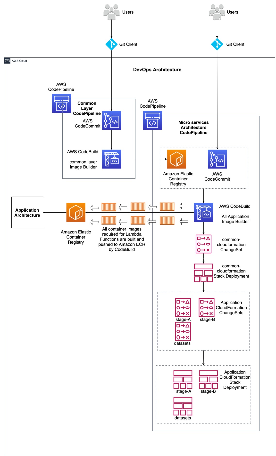
DevOps Architecture

Lambda-docker-images-DevOps-Architecture

Application Architecture

lambda-docker-image-microservices-app

In the above architecture diagram, two architectures are combined, namely 1, DevOps Architecture and 2, Microservices Application Architecture. DevOps architecture demonstrates the use of AWS Developer services such as AWS CodeCommit, AWS CodePipeline, AWS CodeBuild along with Amazon Elastic Container Repository (ECR) and AWS CloudFormation. These are used to support Continuous Integration and Continuous Deployment/Delivery (CI/CD) for both infrastructure and application code. Microservices Application architecture demonstrates how various AWS Lambda Functions that are part of microservices utilize container images for application code. This post will focus on performing CI/CD for Lambda functions utilizing container containers. The application code used in here is a simpler version taken from Serverless DataLake Framework (SDLF). For more information, refer to the AWS Samples GitHub repository for SDLF here.

DevOps workflow

There are two CodePipelines: one for building and pushing the common layer docker image to Amazon ECR, and another for building and pushing the docker images for all the Lambda Functions within the microservices architecture to Amazon ECR, as well as deploying the microservices architecture involving Lambda Functions via CloudFormation. Common layer container image functions as a common layer in all other Lambda Function container images, therefore its code is maintained in a separate CodeCommit repository used as a source stage for a CodePipeline. Common layer CodePipeline takes the code from the CodeCommit repository and passes the artifact to a CodeBuild project that builds the container image and pushes it to an Amazon ECR repository. This common layer ECR repository functions as a source in addition to the CodeCommit repository holding the code for all other Lambda Functions and resources involved in the microservices architecture CodePipeline.

Due to all or the majority of the Lambda Functions in the microservices architecture requiring the common layer container image as a layer, any change made to it should invoke the microservices architecture CodePipeline that builds the container images for all Lambda Functions. Moreover, a CodeCommit repository holding the code for every resource in the microservices architecture is another source to that CodePipeline to get invoked. This has two sources, because the container images in the microservices architecture should be built for changes in the common layer container image as well as for the code changes made and pushed to the CodeCommit repository.

Below is the sample dockerfile that uses the common layer container image as a layer:

ARG ECR_COMMON_DATALAKE_REPO_URL
FROM ${ECR_COMMON_DATALAKE_REPO_URL}:latest AS layer
FROM public.ecr.aws/lambda/python:3.8
# Layer Code
WORKDIR /opt
COPY --from=layer /opt/ .
# Function Code
WORKDIR /var/task
COPY src/lambda_function.py .
CMD ["lambda_function.lambda_handler"]

where the argument ECR_COMMON_DATALAKE_REPO_URL should resolve to the ECR url for common layer container image, which is provided to the --build-args along with docker build command. For example:

export ECR_COMMON_DATALAKE_REPO_URL="0123456789.dkr.ecr.us-east-2.amazonaws.com/dev-routing-lambda"
docker build --build-arg ECR_COMMON_DATALAKE_REPO_URL=$ECR_COMMON_DATALAKE_REPO_URL .

Deploying a Sample

  • Step1: Clone the repository Codepipeline-lambda-docker-images to your workstation. If using the zip file, then unzip the file to a local directory.
    • git clone https://github.com/aws-samples/codepipeline-lambda-docker-images.git
  • Step 2: Change the directory to the cloned directory or extracted directory. The local code repository structure should appear as follows:
    • cd codepipeline-lambda-docker-images

code-repository-structure

  • Step 3: Deploy the CloudFormation stack used in the template file CodePipelineTemplate/codepipeline.yaml to your AWS account. This deploys the resources required for DevOps architecture involving AWS CodePipelines for common layer code and microservices architecture code. Deploy CloudFormation stacks using the AWS console by following the documentation here, providing the name for the stack (for example datalake-infra-resources) and passing the parameters while navigating the console. Furthermore, use the AWS CLI to deploy a CloudFormation stack by following the documentation here.
  • Step 4: When the CloudFormation Stack deployment completes, navigate to the AWS CloudFormation console and to the Outputs section of the deployed stack, then note the CodeCommit repository urls. Three CodeCommit repo urls are available in the CloudFormation stack outputs section for each CodeCommit repository. Choose one of them based on the way you want to access it. Refer to the following documentation Setting up for AWS CodeCommit. I will be using the git-remote-codecommit (grc) method throughout this post for CodeCommit access.
  • Step 5: Clone the CodeCommit repositories and add code:
      • Common Layer CodeCommit repository: Take the value of the Output for the key oCommonLayerCodeCommitHttpsGrcRepoUrl from datalake-infra-resources CloudFormation Stack Outputs section which looks like below:

    commonlayercodeoutput

      • Clone the repository:
        • git clone codecommit::us-east-2://dev-CommonLayerCode
      • Change the directory to dev-CommonLayerCode
        • cd dev-CommonLayerCode
      •  Add contents to the cloned repository from the source code downloaded in Step 1. Copy the code from the CommonLayerCode directory and the repo contents should appear as follows:

    common-layer-repository

      • Create the main branch and push to the remote repository
        git checkout -b main
        git add ./
        git commit -m "Initial Commit"
        git push -u origin main
      • Application CodeCommit repository: Take the value of the Output for the key oAppCodeCommitHttpsGrcRepoUrl from datalake-infra-resources CloudFormation Stack Outputs section which looks like below:

    appcodeoutput

      • Clone the repository:
        • git clone codecommit::us-east-2://dev-AppCode
      • Change the directory to dev-CommonLayerCode
        • cd dev-AppCode
      • Add contents to the cloned repository from the source code downloaded in Step 1. Copy the code from the ApplicationCode directory and the repo contents should appear as follows from the root:

    app-layer-repository

    • Create the main branch and push to the remote repository
      git checkout -b main
      git add ./
      git commit -m "Initial Commit"
      git push -u origin main

What happens now?

  • Now the Common Layer CodePipeline goes to the InProgress state and invokes the Common Layer CodeBuild project that builds the docker image and pushes it to the Common Layer Amazon ECR repository. The image tag utilized for the container image is the value resolved for the environment variable available in the AWS CodeBuild project CODEBUILD_RESOLVED_SOURCE_VERSION. This is the CodeCommit git Commit Id in this case.
    For example, if the CommitId in CodeCommit is f1769c87, then the pushed docker image will have this tag along with latest
  • buildspec.yaml files appears as follows:
    version: 0.2
    phases:
      install:
        runtime-versions:
          docker: 19
      pre_build:
        commands:
          - echo Logging in to Amazon ECR...
          - aws --version
          - $(aws ecr get-login --region $AWS_DEFAULT_REGION --no-include-email)
          - REPOSITORY_URI=$ECR_COMMON_DATALAKE_REPO_URL
          - COMMIT_HASH=$(echo $CODEBUILD_RESOLVED_SOURCE_VERSION | cut -c 1-7)
          - IMAGE_TAG=${COMMIT_HASH:=latest}
      build:
        commands:
          - echo Build started on `date`
          - echo Building the Docker image...          
          - docker build -t $REPOSITORY_URI:latest .
          - docker tag $REPOSITORY_URI:latest $REPOSITORY_URI:$IMAGE_TAG
      post_build:
        commands:
          - echo Build completed on `date`
          - echo Pushing the Docker images...
          - docker push $REPOSITORY_URI:latest
          - docker push $REPOSITORY_URI:$IMAGE_TAG
  • Now the microservices architecture CodePipeline goes to the InProgress state and invokes all of the application image builder CodeBuild project that builds the docker images and pushes them to the Amazon ECR repository.
    • To improve the performance, every docker image is built in parallel within the codebuild project. The buildspec.yaml executes the build.sh script. This has the logic to build docker images required for each Lambda Function part of the microservices architecture. The docker images used for this sample architecture took approximately 4 to 5 minutes when the docker images were built serially. After switching to parallel building, it took approximately 40 to 50 seconds.
    • buildspec.yaml files appear as follows:
      version: 0.2
      phases:
        install:
          runtime-versions:
            docker: 19
          commands:
            - uname -a
            - set -e
            - chmod +x ./build.sh
            - ./build.sh
      artifacts:
        files:
          - cfn/**/*
        name: builds/$CODEBUILD_BUILD_NUMBER/cfn-artifacts
    • build.sh file appears as follows:
      #!/bin/bash
      set -eu
      set -o pipefail
      
      RESOURCE_PREFIX="${RESOURCE_PREFIX:=stg}"
      AWS_DEFAULT_REGION="${AWS_DEFAULT_REGION:=us-east-1}"
      ACCOUNT_ID=$(aws sts get-caller-identity --query Account --output text 2>&1)
      ECR_COMMON_DATALAKE_REPO_URL="${ECR_COMMON_DATALAKE_REPO_URL:=$ACCOUNT_ID.dkr.ecr.$AWS_DEFAULT_REGION.amazonaws.com\/$RESOURCE_PREFIX-common-datalake-library}"
      pids=()
      pids1=()
      
      PROFILE='new-profile'
      aws configure --profile $PROFILE set credential_source EcsContainer
      
      aws --version
      $(aws ecr get-login --region $AWS_DEFAULT_REGION --no-include-email)
      COMMIT_HASH=$(echo $CODEBUILD_RESOLVED_SOURCE_VERSION | cut -c 1-7)
      BUILD_TAG=build-$(echo $CODEBUILD_BUILD_ID | awk -F":" '{print $2}')
      IMAGE_TAG=${BUILD_TAG:=COMMIT_HASH:=latest}
      
      cd dockerfiles;
      mkdir ../logs
      function pwait() {
          while [ $(jobs -p | wc -l) -ge $1 ]; do
              sleep 1
          done
      }
      
      function build_dockerfiles() {
          if [ -d $1 ]; then
              directory=$1
              cd $directory
              echo $directory
              echo "---------------------------------------------------------------------------------"
              echo "Start creating docker image for $directory..."
              echo "---------------------------------------------------------------------------------"
                  REPOSITORY_URI=$ACCOUNT_ID.dkr.ecr.$AWS_DEFAULT_REGION.amazonaws.com/$RESOURCE_PREFIX-$directory
                  docker build --build-arg ECR_COMMON_DATALAKE_REPO_URL=$ECR_COMMON_DATALAKE_REPO_URL . -t $REPOSITORY_URI:latest -t $REPOSITORY_URI:$IMAGE_TAG -t $REPOSITORY_URI:$COMMIT_HASH
                  echo Build completed on `date`
                  echo Pushing the Docker images...
                  docker push $REPOSITORY_URI
              cd ../
              echo "---------------------------------------------------------------------------------"
              echo "End creating docker image for $directory..."
              echo "---------------------------------------------------------------------------------"
          fi
      }
      
      for directory in *; do 
         echo "------Started processing code in $directory directory-----"
         build_dockerfiles $directory 2>&1 1>../logs/$directory-logs.log | tee -a ../logs/$directory-logs.log &
         pids+=($!)
         pwait 20
      done
      
      for pid in "${pids[@]}"; do
        wait "$pid"
      done
      
      cd ../cfn/
      function build_cfnpackages() {
          if [ -d ${directory} ]; then
              directory=$1
              cd $directory
              echo $directory
              echo "---------------------------------------------------------------------------------"
              echo "Start packaging cloudformation package for $directory..."
              echo "---------------------------------------------------------------------------------"
              aws cloudformation package --profile $PROFILE --template-file template.yaml --s3-bucket $S3_BUCKET --output-template-file packaged-template.yaml
              echo "Replace the parameter 'pEcrImageTag' value with the latest built tag"
              echo $(jq --arg Image_Tag "$IMAGE_TAG" '.Parameters |= . + {"pEcrImageTag":$Image_Tag}' parameters.json) > parameters.json
              cat parameters.json
              ls -al
              cd ../
              echo "---------------------------------------------------------------------------------"
              echo "End packaging cloudformation package for $directory..."
              echo "---------------------------------------------------------------------------------"
          fi
      }
      
      for directory in *; do
          echo "------Started processing code in $directory directory-----"
          build_cfnpackages $directory 2>&1 1>../logs/$directory-logs.log | tee -a ../logs/$directory-logs.log &
          pids1+=($!)
          pwait 20
      done
      
      for pid in "${pids1[@]}"; do
        wait "$pid"
      done
      
      cd ../logs/
      ls -al
      for f in *; do
        printf '%s\n' "$f"
        paste /dev/null - < "$f"
      done
      
      cd ../
      

The function build_dockerfiles() loops through each directory within the dockerfiles directory and runs the docker build command in order to build the docker image. The name for the docker image and then the ECR repository is determined by the directory name in which the DockerFile is used from. For example, if the DockerFile directory is routing-lambda and the environment variables take the below values,

ACCOUNT_ID=0123456789
AWS_DEFAULT_REGION=us-east-2
RESOURCE_PREFIX=dev
directory=routing-lambda
REPOSITORY_URI=$ACCOUNT_ID.dkr.ecr.$AWS_DEFAULT_REGION.amazonaws.com/$RESOURCE_PREFIX-$directory

Then REPOSITORY_URI becomes 0123456789.dkr.ecr.us-east-2.amazonaws.com/dev-routing-lambda
And the docker image is pushed to this resolved REPOSITORY_URI. Similarly, docker images for all other directories are built and pushed to Amazon ECR.

Important Note: The ECR repository names match the directory names where the DockerFiles exist and was already created as part of the CloudFormation template codepipeline.yaml that was deployed in step 3. In order to add more Lambda Functions to the microservices architecture, make sure that the ECR repository name added to the new repository in the codepipeline.yaml template matches the directory name within the AppCode repository dockerfiles directory.

Every docker image is built in parallel in order to save time. Each runs as a separate operating system process and is pushed to the Amazon ECR repository. This also controls the number of processes that could run in parallel by setting a value for the variable pwait within the loop. For example, if pwait 20, then the maximum number of parallel processes is 20 at a given time. The image tag for all docker images used for Lambda Functions is constructed via the CodeBuild BuildId, which is available via environment variable $CODEBUILD_BUILD_ID, in order to ensure that a new image gets a new tag. This is required for CloudFormation to detect changes and update Lambda Functions with the new container image tag.

Once every docker image is built and pushed to Amazon ECR in the CodeBuild project, it builds every CloudFormation package by uploading all local artifacts to Amazon S3 via AWS Cloudformation package CLI command for the templates available in its own directory within the cfn directory. Moreover, it updates every parameters.json file for each directory with the ECR image tag to the parameter value pEcrImageTag. This is required for CloudFormation to detect changes and update the Lambda Function with the new image tag.

After this, the CodeBuild project will output the packaged CloudFormation templates and parameters files as an artifact to AWS CodePipeline so that it can be deployed via AWS CloudFormation in further stages. This is done by first creating a ChangeSet and then deploying it at the next stage.

Testing the microservices architecture

As stated above, the sample application utilized for microservices architecture involving multiple Lambda Functions is a modified version of the Serverless Data Lake Framework. The microservices architecture CodePipeline deployed every AWS resource required to run the SDLF application via AWS CloudFormation stages. As part of SDLF, it also deployed a set of DynamoDB tables required for the applications to run. I utilized the meteorites sample for this, thereby the DynamoDb tables should be added with the necessary data for the application to run for this sample.

Utilize the AWS console to write data to the AWS DynamoDb Table. For more information, refer to this documentation. The sample json files are in the utils/DynamoDbConfig/ directory.

1. Add the record below to the octagon-Pipelines-dev DynamoDB table:

{
"description": "Main Pipeline to Ingest Data",
"ingestion_frequency": "WEEKLY",
"last_execution_date": "2020-03-11",
"last_execution_duration_in_seconds": 4.761,
"last_execution_id": "5445249c-a097-447a-a957-f54f446adfd2",
"last_execution_status": "COMPLETED",
"last_execution_timestamp": "2020-03-11T02:34:23.683Z",
"last_updated_timestamp": "2020-03-11T02:34:23.683Z",
"modules": [
{
"name": "pandas",
"version": "0.24.2"
},
{
"name": "Python",
"version": "3.7"
}
],
"name": "engineering-main-pre-stage",
"owner": "Yuri Gagarin",
"owner_contact": "y.gagarin@",
"status": "ACTIVE",
"tags": [
{
"key": "org",
"value": "VOSTOK"
}
],
"type": "INGESTION",
"version": 127
}

2. Add the record below to the octagon-Pipelines-dev DynamoDB table:

{
"description": "Main Pipeline to Merge Data",
"ingestion_frequency": "WEEKLY",
"last_execution_date": "2020-03-11",
"last_execution_duration_in_seconds": 570.559,
"last_execution_id": "0bb30d20-ace8-4cb2-a9aa-694ad018694f",
"last_execution_status": "COMPLETED",
"last_execution_timestamp": "2020-03-11T02:44:36.069Z",
"last_updated_timestamp": "2020-03-11T02:44:36.069Z",
"modules": [
{
"name": "PySpark",
"version": "1.0"
}
],
"name": "engineering-main-post-stage",
"owner": "Neil Armstrong",
"owner_contact": "n.armstrong@",
"status": "ACTIVE",
"tags": [
{
"key": "org",
"value": "NASA"
}
],
"type": "TRANSFORM",
"version": 4
}

3. Add the record below to the octagon-Datsets-dev DynamoDB table:

{
"classification": "Orange",
"description": "Meteorites Name, Location and Classification",
"frequency": "DAILY",
"max_items_process": 250,
"min_items_process": 1,
"name": "engineering-meteorites",
"owner": "NASA",
"owner_contact": "[email protected]",
"pipeline": "main",
"tags": [
{
"key": "cost",
"value": "meteorites division"
}
],
"transforms": {
"stage_a_transform": "light_transform_blueprint",
"stage_b_transform": "heavy_transform_blueprint"
},
"type": "TRANSACTIONAL",
"version": 1
}


If you want to create these samples using AWS CLI, please refer to this documentation.

Record 1:

aws dynamodb put-item --table-name octagon-Pipelines-dev --item '{"description":{"S":"Main Pipeline to Merge Data"},"ingestion_frequency":{"S":"WEEKLY"},"last_execution_date":{"S":"2021-03-16"},"last_execution_duration_in_seconds":{"N":"930.097"},"last_execution_id":{"S":"e23b7dae-8e83-4982-9f97-5784a9831a14"},"last_execution_status":{"S":"COMPLETED"},"last_execution_timestamp":{"S":"2021-03-16T04:31:16.968Z"},"last_updated_timestamp":{"S":"2021-03-16T04:31:16.968Z"},"modules":{"L":[{"M":{"name":{"S":"PySpark"},"version":{"S":"1.0"}}}]},"name":{"S":"engineering-main-post-stage"},"owner":{"S":"Neil Armstrong"},"owner_contact":{"S":"n.armstrong@"},"status":{"S":"ACTIVE"},"tags":{"L":[{"M":{"key":{"S":"org"},"value":{"S":"NASA"}}}]},"type":{"S":"TRANSFORM"},"version":{"N":"8"}}'

Record 2:

aws dynamodb put-item --table-name octagon-Pipelines-dev --item '{"description":{"S":"Main Pipeline to Ingest Data"},"ingestion_frequency":{"S":"WEEKLY"},"last_execution_date":{"S":"2021-03-28"},"last_execution_duration_in_seconds":{"N":"1.75"},"last_execution_id":{"S":"7e0e04e7-b05e-41a6-8ced-829d47866a6a"},"last_execution_status":{"S":"COMPLETED"},"last_execution_timestamp":{"S":"2021-03-28T20:23:06.031Z"},"last_updated_timestamp":{"S":"2021-03-28T20:23:06.031Z"},"modules":{"L":[{"M":{"name":{"S":"pandas"},"version":{"S":"0.24.2"}}},{"M":{"name":{"S":"Python"},"version":{"S":"3.7"}}}]},"name":{"S":"engineering-main-pre-stage"},"owner":{"S":"Yuri Gagarin"},"owner_contact":{"S":"y.gagarin@"},"status":{"S":"ACTIVE"},"tags":{"L":[{"M":{"key":{"S":"org"},"value":{"S":"VOSTOK"}}}]},"type":{"S":"INGESTION"},"version":{"N":"238"}}'

Record 3:

aws dynamodb put-item --table-name octagon-Pipelines-dev --item '{"description":{"S":"Main Pipeline to Ingest Data"},"ingestion_frequency":{"S":"WEEKLY"},"last_execution_date":{"S":"2021-03-28"},"last_execution_duration_in_seconds":{"N":"1.75"},"last_execution_id":{"S":"7e0e04e7-b05e-41a6-8ced-829d47866a6a"},"last_execution_status":{"S":"COMPLETED"},"last_execution_timestamp":{"S":"2021-03-28T20:23:06.031Z"},"last_updated_timestamp":{"S":"2021-03-28T20:23:06.031Z"},"modules":{"L":[{"M":{"name":{"S":"pandas"},"version":{"S":"0.24.2"}}},{"M":{"name":{"S":"Python"},"version":{"S":"3.7"}}}]},"name":{"S":"engineering-main-pre-stage"},"owner":{"S":"Yuri Gagarin"},"owner_contact":{"S":"y.gagarin@"},"status":{"S":"ACTIVE"},"tags":{"L":[{"M":{"key":{"S":"org"},"value":{"S":"VOSTOK"}}}]},"type":{"S":"INGESTION"},"version":{"N":"238"}}'

Now upload the sample json files to the raw s3 bucket. The raw S3 bucket name can be obtained in the output of the common-cloudformation stack deployed as part of the microservices architecture CodePipeline. Navigate to the CloudFormation console in the region where the CodePipeline was deployed and locate the stack with the name common-cloudformation, navigate to the Outputs section, and then note the output bucket name with the key oCentralBucket. Navigate to the Amazon S3 Bucket console and locate the bucket for oCentralBucket, create two path directories named engineering/meteorites, and upload every sample json file to this directory. Meteorites sample json files are available in the utils/meteorites-test-json-files directory of the previously cloned repository. Wait a few minutes and then navigate to the stage bucket noted from the common-cloudformation stack output name oStageBucket. You can see json files converted into csv in pre-stage/engineering/meteorites folder in S3. Wait a few more minutes and then navigate to the post-stage/engineering/meteorites folder in the oStageBucket to see the csv files converted to parquet format.


Cleanup

Navigate to the AWS CloudFormation console, note the S3 bucket names from the common-cloudformation stack outputs, and empty the S3 buckets. Refer to Emptying the Bucket for more information.

Delete the CloudFormation stacks in the following order:
1. Common-Cloudformation
2. stagea
3. stageb
4. sdlf-engineering-meteorites
Then delete the infrastructure CloudFormation stack datalake-infra-resources deployed using the codepipeline.yaml template. Refer to the following documentation to delete CloudFormation Stacks: Deleting a stack on the AWS CloudFormation console or Deleting a stack using AWS CLI.


Conclusion

This method lets us use CI/CD via CodePipeline, CodeCommit, and CodeBuild, along with other AWS services, to automatically deploy container images to Lambda Functions that are part of the microservices architecture. Furthermore, we can build a common layer that is equivalent to the Lambda layer that could be built independently via its own CodePipeline, and then build the container image and push to Amazon ECR. Then, the common layer container image Amazon ECR functions as a source along with its own CodeCommit repository which holds the code for the microservices architecture CodePipeline. Having two sources for microservices architecture codepipeline lets us build every docker image. This is due to a change made to the common layer docker image that is referred to in other docker images, and another source that holds the code for other microservices including Lambda Function.


About the Author

kirankumar.jpeg Kirankumar Chandrashekar is a Sr.DevOps consultant at AWS Professional Services. He focuses on leading customers in architecting DevOps technologies. Kirankumar is passionate about DevOps, Infrastructure as Code, and solving complex customer issues. He enjoys music, as well as cooking and traveling.


Secure and analyse your Terraform code using AWS CodeCommit, AWS CodePipeline, AWS CodeBuild and tfsec

Post Syndicated from César Prieto Ballester original https://aws.amazon.com/blogs/devops/secure-and-analyse-your-terraform-code-using-aws-codecommit-aws-codepipeline-aws-codebuild-and-tfsec/

Introduction

More and more customers are using Infrastructure-as-Code (IaC) to design and implement their infrastructure on AWS. This is why it is essential to have pipelines with Continuous Integration/Continuous Deployment (CI/CD) for infrastructure deployment. HashiCorp Terraform is one of the popular IaC tools for customers on AWS.

In this blog, I will guide you through building a CI/CD pipeline on AWS to analyze and identify possible configurations issues in your Terraform code templates. This will help mitigate security risks within our infrastructure deployment pipelines as part of our CI/CD. To do this, we utilize AWS tools and the Open Source tfsec tool, a static analysis security scanner for your Terraform code, including more than 90 preconfigured checks with the ability to add custom checks.

Solutions Overview

The architecture goes through a CI/CD pipeline created on AWS using AWS CodeCommit, AWS CodePipeline, AWS CodeBuild, and Amazon ECR.

Our demo has two separate pipelines:

  1. CI/CD Pipeline to build and push our custom Docker image to Amazon ECR
  2. CI/CD Pipeline where our tfsec analysis is executed and Terraform provisions infrastructure

The tfsec configuration and Terraform goes through a buildspec specification file defined within an AWS CodeBuild action. This action will calculate how many potential security risks we currently have within our Terraform templates, which will be displayed in our manual acceptance process for verification.

Architecture diagram

Provisioning the infrastructure

We have created an AWS Cloud Development Kit (AWS CDK) app hosted in a Git Repository written in Python. Here you can deploy the two main pipelines in order to manage this scenario. For a list of the deployment prerequisites, see the README.md file.

Clone the repo in your local machine. Then, bootstrap and deploy the CDK stack:

git clone https://github.com/aws-samples/aws-cdk-tfsec
cd aws-cdk-tfsec
pip install -r requirements.txt
cdk bootstrap aws://account_id/eu-west-1
cdk deploy --all

The infrastructure creation takes around 5-10 minutes due the AWS CodePipelines and referenced repository creation. Once the CDK has deployed the infrastructure, clone the two new AWS CodeCommit repos that have already been created and push the example code. First, one for the custom Docker image, and later for your Terraform code, like this:

git clone https://git-codecommit.eu-west-1.amazonaws.com/v1/repos/awsome-terraform-example-container
cd awsome-terraform-example-container
git checkout -b main
cp repos/docker_image/* .
git add .
git commit -am "First commit"
git push origin main

Once the Docker image is built and pushed to the Amazon ECR, proceed with Terraform repo. Check the pipeline process on the AWS CodePipeline console.

Screenshot of CI/CD Pipeline to build Docker Image

git clone https://git-codecommit.eu-west-1.amazonaws.com/v1/repos/awsome-terraform-example
cd awsome-terraform-example
git checkout -b main
cp -aR repos/terraform_code/* .
git add .
git commit -am "First commit"
git push origin main

The Terraform provisioning AWS CodePipeline has the following aspect:

Screenshot of CodePipeline to run security and orchestrate IaC

The pipeline has three main stages:

  • Source – AWS CodeCommit stores the Terraform repository infrastructure and every time we push code to the main branch the AWS CodePipeline will be triggered.
  • tfsec analysis – AWS CodeBuild looks for a buildspec to execute the tfsec actions configured on the same buildspec.

Screenshot showing tfsec analysis

The output shows the potential security issues detected by tfsec for our Terraform code. The output is linking to the different security issues already defined on tfsec. Check the security checks defined by tfsec here. After tfsec execution, a manual approval action is set up to decide if we should go for the next steps or if we reject and stop the AWS CodePipeline execution.

The URL for review is linking to our tfsec output console.

Screenshot of tfsec output


  • Terraform plan and Terraform apply – This will be applied to our infrastructure plan. After the Terraform plan command and before the Terraform apply, a manual action is set up to decide if we can apply the changes.

After going through all of the stages, our Terraform infrastructure should be created.

Clean up

After completing your demo, feel free to delete your stack using the CDK cli:

cdk destroy --all

Conclusion

At AWS, security is our top priority. This post demonstrates how to build a CI/CD pipeline by using AWS Services to automate and secure your infrastructure as code via Terraform and tfsec.

Learn more about tfsec through the official documentation: https://tfsec.dev/

About the authors


César Prieto Ballester is a DevOps Consultant at Amazon Web Services. He enjoys automating everything and building infrastructure using code. Apart from work, he plays electric guitar and loves riding his mountain bike.


Bruno Bardelli is a Senior DevOps Consultant at Amazon Web Services. He loves to build applications and in his free time plays video games, practices aikido, and goes on walks with his dog.

Choosing a CI/CD approach: AWS Services with BigHat Biosciences

Post Syndicated from Mike Apted original https://aws.amazon.com/blogs/devops/choosing-ci-cd-aws-services-bighat-biosciences/

Founded in 2019, BigHat Biosciences’ mission is to improve human health by reimagining antibody discovery and engineering to create better antibodies faster. Their integrated computational + experimental approach speeds up antibody design and discovery by combining high-speed molecular characterization with machine learning technologies to guide the search for better antibodies. They apply these design capabilities to develop new generations of safer and more effective treatments for patients suffering from today’s most challenging diseases. Their platform, from wet lab robots to cloud-based data and logistics plane, is woven together with rapidly changing BigHat-proprietary software. BigHat uses continuous integration and continuous deployment (CI/CD) throughout their data engineering workflows and when training and evaluating their machine learning (ML) models.


BigHat Biosciences Logo


In a previous post, we discussed the key considerations when choosing a CI/CD approach. In this post, we explore BigHat’s decisions and motivations in adopting managed AWS CI/CD services. You may find that your organization has commonalities with BigHat and some of their insights may apply to you. Throughout the post, considerations are informed and choices are guided by the best practices in the AWS Well-Architected Framework.

How did BigHat decide what they needed?

Making decisions on appropriate (CI/CD) solutions requires understanding the characteristics of your organization, the environment you operate in, and your current priorities and goals.

“As a company designing therapeutics for patients rather than software, the role of technology at BigHat is to enable a radically better approach to develop therapeutic molecules,” says Eddie Abrams, VP of Engineering at BigHat. “We need to automate as much as possible. We need the speed, agility, reliability and reproducibility of fully automated infrastructure to enable our company to solve complex problems with maximum scientific rigor while integrating best in class data analysis. Our engineering-first approach supports that.”

BigHat possesses a unique insight to an unsolved problem. As an early stage startup, their core focus is optimizing the fully integrated platform that they built from the ground-up to guide the design for better molecules. They respond to feedback from partners and learn from their own internal experimentation. With each iteration, the quality of what they’re creating improves, and they gain greater insight and improved models to support the next iteration. More than anything, they need to be able to iterate rapidly. They don’t need any additional complexity that would distract from their mission. They need uncomplicated and enabling solutions.

They also have to take into consideration the regulatory requirements that apply to them as a company, the data they work with and its security requirements; and the market segment they compete in. Although they don’t control these factors, they can control how they respond to them, and they want to be able to respond quickly. It’s not only speed that matters in designing for security and compliance, but also visibility and track-ability. These often overlooked and critical considerations are instrumental in choosing a CI/CD strategy and platform.

“The ability to learn faster than your competitors may be the only sustainable competitive advantage,” says Cindy Alvarez in her book Lean Customer Development.

The tighter the feedback loop, the easier it is to make a change. Rapid iteration allows BigHat to easily build upon what works, and make adjustments as they identify avenues that won’t lead to success.

Feature set

CI/CD is applicable to more than just the traditional use case. It doesn’t have to be software delivered in a classic fashion. In the case of BigHat, they apply CI/CD in their data engineering workflows and in training their ML models. BigHat uses automated solutions in all aspects of their workflow. Automation further supports taking what they have created internally and enabling advances in antibody design and development for safer, more effective treatments of conditions.

“We see a broadening of the notion of what can come under CI/CD,” says Abrams. “We use automated solutions wherever possible including robotics to perform scaled assays. The goal in tightening the loop is to improve precision and speed, and reduce latency and lag time.”

BigHat reached the conclusion that they would adopt managed service offerings wherever possible, including in their CI/CD tooling and other automation initiatives.

“The phrase ‘undifferentiated heavy lifting’ has always resonated,” says Abrams. “Building, scaling, and operating core software and infrastructure are hard problems, but solving them isn’t itself a differentiating advantage for a therapeutics company. But whether we can automate that infrastructure, and how we can use that infrastructure at scale on a rock solid control plane to provide our custom solutions iteratively, reliably and efficiently absolutely does give us an edge. We need an end-to-end, complete infrastructure solution that doesn’t force us to integrate a patchwork of solutions ourselves. AWS provides exactly what we need in this regard.”

Reducing risk

Startups can be full of risk, with the upside being potential future reward. They face risk in finding the right problem, in finding a solution to that problem, and in finding a viable customer base to buy that solution.

A key priority for early stage startups is removing risk from as many areas of the business as possible. Any steps an early stage startup can take to remove risk without commensurately limiting reward makes them more viable. The more risk a startup can drive out of their hypothesis the more likely their success, in part because they’re more attractive to customers, employees, and investors alike. The more likely their product solves their problem, the more willing a customer is to give it a chance. Likewise, the more attractive they are to investors when compared to alternative startups with greater risk in reaching their next major milestone.

Adoption of managed services for CI/CD accomplishes this goal in several ways. The most important advantage remains speed. The core functionality required can be stood up very quickly, as it’s an existing service. Customers have a large body of reference examples and documentation available to demonstrate how to use that service. They also insulate teams from the need to configure and then operate the underlying infrastructure. The team remains focused on their differentiation and their core value proposition.

“We are automated right up to the organizational level and because of this, running those services ourselves represents operational risk,” says Abrams. “The largest day-to-day infrastructure risk to us is having the business stalled while something is not working. Do I want to operate these services, and focus my staff on that? There is no guarantee I can just throw more compute at a self-managed software service I’m running and make it scale effectively. There is no guarantee that if one datacenter is having a network or electrical problem that I can simply switch to another datacenter. I prefer AWS manages those scale and uptime problems.”

Embracing an opinionated model

BigHat is a startup with a singular focus on using ML to reduce the time and difficulty of designing antibodies and other therapeutic proteins. By adopting managed services, they have removed the burden of implementing and maintaining CI/CD systems.

Accepting the opinionated guardrails of the managed service approach allows, and to a degree reinforces, the focus on what makes a startup unique. Rather than being focused on performance tuning, making decisions on what OS version to use, or which of the myriad optional puzzle pieces to put together, they can use a well-integrated set of tools built to work with each other in a defined fashion.

The opinionated model means best practices are baked into the toolchain. Instead of hiring for specialized administration skills they’re hiring for specialized biotech skills.

“The only degrees of freedom I care about are the ones that improve our technologies and reduce the time, cost, and risk of bringing a therapeutic to market,” says Abrams. “We focus on exactly where we can gain operational advantages by simply adopting managed services that already embrace the Well-Architected Framework. If we had to tackle all of these engineering needs with limited resources, we would be spending into a solved problem. Before AWS, startups just didn’t do these sorts of things very well. Offloading this effort to a trusted partner is pretty liberating.”

Beyond the reduction in operational concerns, BigHat can also expect continuous improvement of that service over time to be delivered automatically by the provider. For their use case they will likely derive more benefit for less cost over time without any investment required.

Overview of solution

BigHat uses the following key services:


BigHat Reference Architecture

Security

Managed services are supported, owned and operated by the provider . This allows BigHat to leave concerns like patching and security of the underlying infrastructure and services to the provider. BigHat continues to maintain ownership in the shared responsibility model, but their scope of concern is significantly narrowed. The surface area the’re responsible for is reduced, helping to minimize risk. Choosing a partner with best in class observability, tracking, compliance and auditing tools is critical to any company that manages sensitive data.

Cost advantages

A startup must also make strategic decisions about where to deploy the capital they have raised from their investors. The vendor managed services bring a model focused on consumption, and allow the startup to make decisions about where they want to spend. This is often referred to as an operational expense (OpEx) model, in other words “pay as you go”, like a utility. This is in contrast to a large upfront investment in both time and capital to build these tools. The lack of need for extensive engineering efforts to stand up these tools, and continued investment to evolve them, acts as a form of capital expenditure (CapEx) avoidance. Startups can allocate their capital where it matters most for them.

“This is corporate-level changing stuff,” says Abrams. “We engage in a weekly leadership review of cost budgets. Operationally I can set the spending knob where I want it monthly, weekly or even daily, and avoid the risks involved in traditional capacity provisioning.”

The right tool for the right time

A key consideration for BigHat was the ability to extend the provider managed tools, where needed, to incorporate extended functionality from the ecosystem. This allows for additional functionality that isn’t covered by the core managed services, while maintaining a focus on their product development versus operating these tools.

Startups must also ask themselves what they need now, versus what they need in the future. As their needs change and grow, they can augment, extend, and replace the tools they have chosen to meet the new requirements. Starting with a vendor-managed service is not a one-way door; it’s an opportunity to defer investment in building and operating these capabilities yourself until that investment is justified. The time to value in using managed services initially doesn’t leave a startup with a sunk cost that limits future options.

“You have to think about the degree you want to adopt a hybrid model for the services you run. Today we aren’t running any software or services that require us to run our own compute instances. It’s very rare we run into something that is hard to do using just the services AWS already provides. Where our needs are not met, we can communicate them to AWS and we can choose to wait for them on their roadmap, which we have done in several cases, or we can elect to do it ourselves,” says Abrams. “This freedom to tweak and expand our service model at will is incomparably liberating.”

Conclusion

BigHat Biosciences was able to make an informed decision by considering the priorities of the business at this stage of its lifecycle. They adopted and embraced opinionated and service provider-managed tooling, which allowed them to inherit a largely best practice set of technology and practices, de-risk their operations, and focus on product velocity and customer feedback. This maintains future flexibility, which delivers significantly more value to the business in its current stage.

“We believe that the underlying engineering, the underlying automation story, is an advantage that applies to every aspect of what we do for our customers,” says Abrams. “By taking those advantages into every aspect of the business, we deliver on operations in a way that provides a competitive advantage a lot of other companies miss by not thinking about it this way.”

About the authors

Mike is a Principal Solutions Architect with the Startup Team at Amazon Web Services. He is a former founder, current mentor, and enjoys helping startups live their best cloud life.


Sean is a Senior Startup Solutions Architect at AWS. Before AWS, he was Director of Scientific Computing at the Howard Hughes Medical Institute.
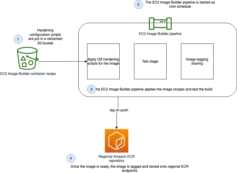
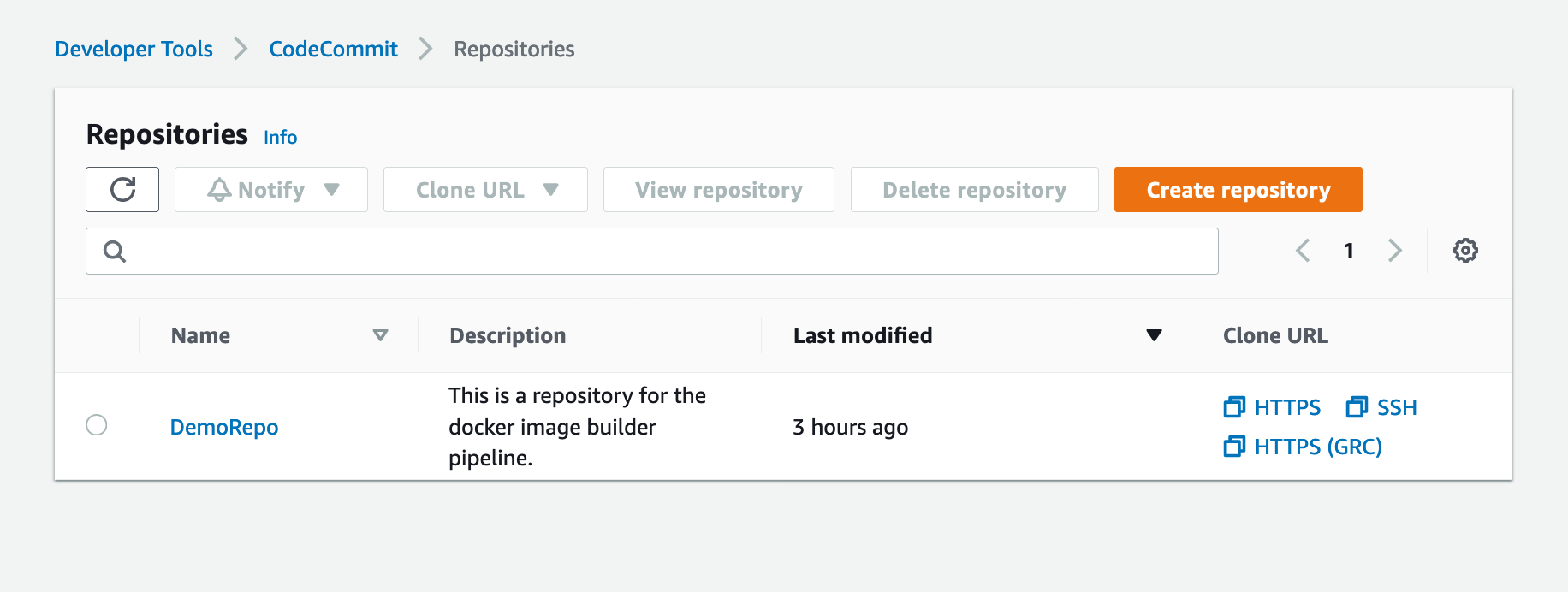
Build and Deploy Docker Images to AWS using EC2 Image Builder

Post Syndicated from Joseph Keating original https://aws.amazon.com/blogs/devops/build-and-deploy-docker-images-to-aws-using-ec2-image-builder/

The NFL, an AWS Professional Services partner, is collaborating with NFL’s Player Health and Safety team to build the Digital Athlete Program. The Digital Athlete Program is working to drive progress in the prevention, diagnosis, and treatment of injuries; enhance medical protocols; and further improve the way football is taught and played. The NFL, in conjunction with AWS Professional Services, delivered an EC2 Image Builder pipeline for automating the production of Docker images. Following similar practices from the Digital Athlete Program, this post demonstrates how to deploy an automated Image Builder pipeline.

“AWS Professional Services faced unique environment constraints, but was able to deliver a modular pipeline solution leveraging EC2 Image Builder. The framework serves as a foundation to create hardened images for future use cases. The team also provided documentation and knowledge transfer sessions to ensure our team was set up to successfully manage the solution.”—Joseph Steinke, Director, Data Solutions Architect, National Football League

A common scenario you may face is how to build Docker images that can be utilized throughout your organization. You may already have existing processes that you’re looking to modernize. You may be looking for a streamlined, managed approach so you can reduce the overhead of operating your own workflows. Additionally, if you’re new to containers, you may be seeking an end-to-end process you can use to deploy containerized workloads. With either case, there is need for a modern, streamlined approach to centralize the configuration and distribution of Docker images. This post demonstrates how to build a secure end-to-end workflow for building secure Docker images.

Image Builder now offers a managed service for building Docker images. With Image Builder, you can automatically produce new up-to-date container images and publish them to specified Amazon Elastic Container Registry (Amazon ECR) repositories after running stipulated tests. You don’t need to worry about the underlying infrastructure. Instead, you can focus simply on your container configuration and use the AWS tools to manage and distribute your images. In this post, we walk through the process of building a Docker image and deploying the image to Amazon ECR, share some security best practices, and demonstrate deploying a Docker image to Amazon Elastic Container Service (Amazon ECS). Additionally, we dive deep into building Docker images following modern principles.

The project we create in this post addresses a use case in which an organization needs an automated workflow for building, distributing, and deploying Docker images. With Image Builder, we build and deploy Docker images and test our image locally that we have created with our Image Builder pipeline.


Solution Overview

The following diagram illustrates our solution architecture.

Show the architecture of the Docker EC2 Image Builder Pipeline

Figure: Show the architecture of the Docker EC2 Image Builder Pipeline


We configure the Image Builder pipeline with AWS CloudFormation. Then we use Amazon Simple Storage Service (Amazon S3) as our source for the pipeline. This means that when we want to update the pipeline with a new Dockerfile, we have to update the source S3 bucket. The pipeline assumes an AWS Identity and Access Management (IAM) role that we generate later in the post. When the pipeline is run, it pulls the latest Dockerfile configuration from Amazon S3, builds a Docker image, and deploys the image to Amazon ECR. Finally, we use AWS Copilot to deploy our Docker image to Amazon ECS. For more information about Copilot, see Applications.

The style in which the Dockerfile application code was written is a personal preference. For more information, see Best practices for writing Dockerfiles.


Overview of AWS services

For this post, we use the following services:

  • EC2 Image BuilderImage Builder is a fully managed AWS service that makes it easy to automate the creation, management, and deployment of customized, secure, and up-to-date server images that are pre-installed and pre-configured with software and settings to meet specific IT standards.
  • Amazon ECRAmazon ECR is an AWS managed container image registry service that is secure, scalable, and reliable.
  • CodeCommit – AWS CodeCommit is a fully-managed source control service that hosts secure Git-based repositories.
  • AWS KMS – Amazon Key Management Service (AWS KMS) is a fully managed service for creating and managing cryptographic keys. These keys are natively integrated with most AWS services. You use a KMS key in this post to encrypt resources.
  • Amazon S3Amazon Simple Storage Service (Amazon S3) is an object storage service utilized for storing and encrypting data. We use Amazon S3 to store our configuration files.
  • AWS CloudFormation – AWS CloudFormation allows you to use domain-specific languages or simple text files to model and provision, in an automated and secure manner, all the resources needed for your applications across all Regions and accounts. You can deploy AWS resources in a safe, repeatable manner, and automate the provisioning of infrastructure.


Prerequisites

To provision the pipeline deployment, you must have the following prerequisites:


CloudFormation templates

You use the following CloudFormation templates to deploy several resources:

  • vpc.yml – Contains all the core networking configuration. It deploys the VPC, two private subnets, two public subnets, and the route tables. The private subnets utilize a NAT gateway to communicate to the internet. The public subnets have full outbound access to the internet gateway.
  • kms.yml – Contains the AWS Key Management Service (AWS KMS) configuration that we use for encrypting resources. The KMS key policy is also configured in this template.
  • s3-iam-config.yml – Contains the S3 bucket and IAM roles we use with our Image Builder pipeline.
  • docker-image-builder.yml – Contains the configuration for the Image Builder pipeline that we use to build Docker images.


Docker Overview

Containerizing an application comes with many benefits. By containerizing an application, the application is decoupled from the underlying infrastructure, greater consistency is gained across environments, and the application can now be deployed in a loosely coupled microservice model. The lightweight nature of containers enables teams to spend less time configuring their application and more time building features that create value for their customers. To achieve these great benefits, you need reliable resources to centralize the creation and distribution of your container images. Additionally, you need to understand container fundamentals. Let’s start by reviewing a Docker base image.

In this post, we follow the multi-stage pattern for building our Docker image. With this approach, we can selectively copy artifacts from one phase to another. This allows you to remove anything not critical to the application’s function in the final image. Let’s walk through some of the logic we put into our Docker image to optimize performance and security.

Let’s begin by looking at line 15-25. Here, we are pulling down the latest amazon/aws-cli Docker image. We are leveraging this image so that we can utilize IAM credentials to clone our CodeCommit repository. In lines 15-24 we are installing and configuring our git configuration. Finally, in line 25 we are cloning our application code from our repository.

In this next section, we set environment variables, installing packages, unpack tar files, and set up a custom Java Runtime Environment (JRE). Amazon Corretto is a no-cost, multi-platform, production-ready distribution of the Open Java Development Kit (OpenJDK). One important distinction to make here is how we are utilizing RUN and ADD in the Dockerfile. By configuring our own custom JRE we can remove unnecessary modules from our image. One of our goals with building Docker images is to keep them lightweight, which is why we are taking the extra steps to ensure that we don’t add any unnecessary configuration.

Let’s take a look at the next section of the Dockerfile. Now that we have all the package that we require, we will create a working directory where we will install our demo app. After the application code is pulled down from CodeCommit, we use Maven to build our artifact.

In the following code snippet, we use FROM to begin a new stage in our build. Notice that we are using the same base as our first stage. If objects on the disk/filesystem in in the first stage stay the same, the previous stage cache can be reused. Using this pattern can greatly reduce build time.

Docker images have a single unique digest. This is a SHA-256 value and is known as the immutable identifier for the image. When changes are made to your image, through a Dockerfile update for example, a new image with a new immutable identifier is generated. The immutable identifier is pinned to prevent unexpected behaviors in code due to change or update. You can also prevent man-in-the-middle attacks by adopting this pattern. Additionally, using a SHA can mitigate the risk of having to rely on mutable tags that can be applied or changed to the wrong image by mistake. You can use the following command to check to ensure that no unintended changes occured.

docker images <input_container_image_id> --digests

Lastly, we configure our final stage, in which we create a user and group to manage our application inside the container. As this user, we copy the binaries created from our first stage. With this pattern, you can clearly see the benefit of using stages when building Docker images. Finally, we note the port that should be published with expose for the container and we define our Entrypoint, which is the instruction we use to run our container.


Deploying the CloudFormation templates

To deploy your templates, complete the following steps:

1. Create a directory where we store all of our demo code by running the following from your terminal:

mkdir awsblogrepo && cd awsblogrepo


2. Clone the source code repository found in the following location:

git clone https://github.com/aws-samples/build-and-deploy-docker-images-to-aws-using-ec2-image-builder.git

You now use the AWS CLI to deploy the CloudFormation templates. Make sure to leave the CloudFormation template names as written in this post.


3. Deploy the VPC CloudFormation template:

aws cloudformation create-stack \
--stack-name vpc-config \
--template-body file://templates/vpc.yml \
--parameters file://parameters/vpc-params.json  \
--capabilities CAPABILITY_IAM \
--region us-east-1

The output should look like the following code:

{
    "StackId": "arn:aws:cloudformation:us-east-1:123456789012:stack/vpc-config/12e90fe0-76c9-11eb-9284-12717722e021"
}


4. Open the parameters/kms-params.json file and update the UserARN parameter with your account ID:

[
  {
      "ParameterKey": "KeyName",
      "ParameterValue": "DemoKey"
  },
  {
    "ParameterKey": "UserARN",
    "ParameterValue": "arn:aws:iam::<input_your_account_id>:root"
  }
]


5. Deploy the KMS key CloudFormation template:

aws cloudformation create-stack \
--stack-name kms-config \
--template-body file://templates/kms.yml \
--parameters file://parameters/kms-params.json \
--capabilities CAPABILITY_IAM \
--region us-east-1

The output should look like the following:

{
    "StackId": "arn:aws:cloudformation:us-east-1:123456789012:stack/kms-config/66a663d0-777d-11eb-ad2b-0e84b19d341f"
}


6. Open the parameters/s3-iam-config.json file and update the DemoConfigS3BucketName parameter to a unique name of your choosing:

[
  {
    "ParameterKey" : "Environment",
    "ParameterValue" : "dev"
  },
  {
    "ParameterKey": "NetworkStackName",
    "ParameterValue" : "vpc-config"
  },
  {
    "ParameterKey" : "EC2InstanceRoleName",
    "ParameterValue" : "EC2InstanceRole"
  },
  {
    "ParameterKey" : "DemoConfigS3BucketName",
    "ParameterValue" : "<input_your_unique_bucket_name>"
  },
  {
    "ParameterKey" : "KMSStackName",
    "ParameterValue" : "kms-config"
  }
]


7. Deploy the IAM role configuration template:

aws cloudformation create-stack \
--stack-name s3-iam-config \
--template-body file://templates/s3-iam-config.yml \
--parameters file://parameters/s3-iam-config.json \
--capabilities CAPABILITY_NAMED_IAM \
--region us-east-1

The output should look like the following:

{
    "StackId": "arn:aws:cloudformation:us-east-1:123456789012:stack/s3-iam-config/8b69c270-7782-11eb-a85c-0ead09d00613"
}


8. Open the parameters/kms-params.json file:

[
  {
      "ParameterKey": "KeyName",
      "ParameterValue": "DemoKey"
  },
  {
    "ParameterKey": "UserARN",
    "ParameterValue": "arn:aws:iam::1234567891012:root"
  }
]


9. Add the following values as a comma-separated list to the UserARN parameter key. Make sure to provide your AWS account ID:

arn:aws:iam::<input_your_aws_account_id>:role/EC2ImageBuilderRole

When finished, the file should look similar to the following:

[
  {
      "ParameterKey": "KeyName",
      "ParameterValue": "DemoKey"
  },
  {
    "ParameterKey": "UserARN",
    "ParameterValue": "arn:aws:iam::123456789012:role/EC2ImageBuilderRole,arn:aws:iam::123456789012:root"
  }
]

Now that the AWS KMS parameter file has been updated, you update the AWS KMS CloudFormation stack.


10. Run the following command to update the kms-config stack:

aws cloudformation update-stack \
--stack-name kms-config \
--template-body file://templates/kms.yml \
--parameters file://parameters/kms-params.json \
--capabilities CAPABILITY_IAM \
--region us-east-1

The output should look like the following:

{
    "StackId": "arn:aws:cloudformation:us-east-1:123456789012:stack/kms-config/66a663d0-777d-11eb-ad2b-0e84b19d341f"
}


11. Open the parameters/docker-image-builder-params.json file and update the ImageBuilderBucketName parameter to the bucket name you generated earlier:

[
  {
    "ParameterKey": "Environment",
    "ParameterValue": "dev"
  },
  {
      "ParameterKey": "ImageBuilderBucketName",
      "ParameterValue": "<input_your_s3_bucket_name>"
  },
  {
      "ParameterKey": "NetworkStackName",
      "ParameterValue": "vpc-config"
  },
  {
      "ParameterKey": "KMSStackName",
      "ParameterValue": "kms-config"
  },
  {
      "ParameterKey": "S3ConfigStackName",
      "ParameterValue": "s3-iam-config"
  },
  {
      "ParameterKey": "ECRName",
      "ParameterValue": "demo-ecr"
  }
]


12. Run the following commands to upload the Dockerfile and component file to S3. Make sure to update the s3 bucket name with the name you generated earlier:

aws s3 cp java/Dockerfile s3://<input_your_bucket_name>/Dockerfile && \
aws s3 cp components/component.yml s3://<input_your_bucket_name>/component.yml

The output should look like the following:

upload: java/Dockerfile to s3://demo12345/Dockerfile
upload: components/component.yml to s3://demo12345/component.yml


13. Deploy the docker-image-builder.yml template:

aws cloudformation create-stack \
--stack-name docker-image-builder-config \
--template-body file://templates/docker-image-builder.yml \
--parameters file://parameters/docker-image-builder-params.json \
--capabilities CAPABILITY_NAMED_IAM \
--region us-east-1

The output should look like the following:

{
    "StackId": "arn:aws:cloudformation:us-east-1:123456789012:stack/docker-image-builder/24317190-76f4-11eb-b879-0afa5528cb21"
}


Configure the Repository

You use AWS CodeCommit as your source control repository. You now walk through the steps of deploying our CodeCommit repository:


1. On the CodeCommit console, choose Repositories.


2. Locate your repository and under Clone URL, choose HTTPS.

Shows DemoRepo CodeCommit Repository

Figure: Shows DemoRepo CodeCommit Repository

You clone this repository in the build directory you created when deploying the CloudFormation templates.


3. In your terminal, past the Git URL from the previous step and clone the repository:

git clone https://git-codecommit.us-east-1.amazonaws.com/v1/repos/DemoRepo


4. Now let’s create and push your main branch:

cd DemoRepo
git checkout -b main
touch initial.txt
git add . && git commit -m "Initial commit"
git push -u origin main


5. On the Repositories page of the CodeCommit console, choose DemoRepo.

The following screenshot shows that we have created our main branch and pushed our first commit to our repository.

Shows the DemoRepo main branch

Figure: Shows the DemoRepo main branch


6. Back in your terminal, create a new feature branch:

git checkout -b feature/configure-repo


7. Create the build directories:

mkdir templates; \
mkdir parameters; \
mkdir java; \
mkdir components

You now copy over the configuration files from the cloned GitHub repository to our CodeCommit repository.


8. Run the following command from the awsblogrepo directory you created earlier:

cp -r build-and-deploy-docker-images-to-aws-using-ec2-image-builder/* DemoRepo/


9. Commit and push your changes:

git add . && git commit -m "Copying config files into source control." 
git push --set-upstream origin feature/configure-repo


10. On the CodeCommit console, navigate to DemoRepo.

Shows the DemoRepo CodeCommit Repository

Figure: Shows the DemoRepo CodeCommit Repository


11. In the navigation pane, under Repositories, choose Branches.

Shows the DemoRepo's code

Figure: Shows the DemoRepo’s code


12. Select the feature/configure-repo branch.

Shows the DemoRepo's branches

Figure: Shows the DemoRepo’s branches


13. Choose Create pull request.

Shows the DemoRepo code

Figure: Shows the DemoRepo code


14. For Title, enter Repository Configuration.


15. For Description, enter a brief description.


16. Choose Create pull request.

Shows a pull request for DemoRepo

Figure: Shows a pull request for DemoRepo


17. Choose Merge to merge the pull request.

Shows merge for DemoRepo pull request

Figure: Shows merge for DemoRepo pull request

Now that you have all the code copied into your CodeCommit repository, you now build an image using the Image Builder pipeline.


EC2 Image Builder Deep Dive

With Image Builder, you can build and deploy Docker images to your AWS account. Let’s look at how your Image Builder pipeline is configured.

A recipe defines the source image to use as your starting point to create a new image, along with the set of components that you add to customize your image and verify that everything is working as expected. Take note of the ParentImage property. Here, you’re declaring that the parent image that your pipeline pulls from the latest Amazon Linux image. This enables organizations to define images that they have approved to be utilized downstream by development teams. Having better control over what Docker images development teams are using improves an organization security posture while enabling the developers to have the tools they need readily available. The DockerfileTemplateUri property refers to the location of the Dockerfile that your Image Builder pipeline is deploying. Take some time to review the configuration.


Run the Image Builder Pipeline

Now you build a Docker image by running the pipeline.

1. Update your account ID and run the following command:

aws imagebuilder start-image-pipeline-execution \
--image-pipeline-arn arn:aws:imagebuilder:us-east-1:<input_your_aws_account_id>:image-pipeline/docker-image-builder-config-docker-java-container

The output should look like the following:

{
    "requestId": "87931a2e-cd74-44e9-9be1-948fec0776aa",
    "clientToken": "e0f710be-0776-43ea-a6d7-c10137a554bf",
    "imageBuildVersionArn": "arn:aws:imagebuilder:us-east-1:123456789012:image/docker-image-builder-config-container-recipe/1.0.0/1"
}


2. On the Image Builder console, choose the docker-image-builder-config-docker-java-container pipeline.

 Shows EC2 Image Builder Pipeline status

Figure: Shows EC2 Image Builder Pipeline status

At the bottom of the page, a new Docker image is building.


3. Wait until the image status becomes Available.

Shows docker image building in EC2 Image Builder console

Figure: Shows docker image building in EC2 Image Builder console


4. On the Amazon ECR console, open java-demo-ib.

The Docker image has been successfully created, tagged, and deployed to Amazon ECR from the Image Builder pipeline.

Shows demo-java-ib image in ECR

Figure: Shows demo-java-ib image in ECR


Test the Docker Image Locally

1. On the Amazon ECR console, open java-demo-ib.


2. Copy the image URI.

ECR Screenshot


3. Run the following commands to authenticate to your ECR repository:

aws ecr get-login-password --region us-east-1 | docker login --username AWS --password-stdin <input_your_account_id>.dkr.ecr.us-east-1.amazonaws.com


4. Run the following command in your terminal, and update the Amazon ECR URI with the content you copied from the previous step:

docker pull <input_ecr_image_uri>

You should see output similar to the following:

1.0.0-80: Pulling from demo-java-ib
596ba82af5aa: Pull complete 
6f476912a053: Pull complete 
3e7162a86ef8: Pull complete 
ec7d8bb8d044: Pull complete 
Digest: sha256:14668cda786aa496f406062ce07087d66a14a7022023091e9b953aae0bdf2634
Status: Downloaded newer image for 123456789012.dkr.ecr.us-east-1.amazonaws.com/demo-java-ib:1.0.0-1
123456789012.dkr.ecr.us-east-1.amazonaws.com/demo-java-ib:1.0.0-1


5. Run the following command from your terminal:

docker image ls

You should see output similar to the following:

REPOSITORY                                                  TAG        IMAGE ID       CREATED          SIZE
123456789012.dkr.ecr.us-east-1.amazonaws.com/demo-java-ib   1.0.0-1   ac75e982863c   34 minutes ago   47.3MB


6. Run the following command from your terminal using the IMAGE ID value from the previous output:

docker run -dp 8090:8090 --name java_hello_world -it <docker_image_id> sh

You should see an output similar to the following:

49ea3a278639252058b55ab80c71245d9f00a3e1933a8249d627ce18c3f59ab1


7. Test your container by running the following command:

curl localhost:8090

You should see an output similar to the following:

Hello World!


8. Now that you have verified that your container is working properly, you can stop your container. Run the following command from your terminal:

docker stop java_hello_world


Conclusion

In this article, we showed how to leverage AWS services to automate the creation, management, and distribution of Docker Images. We walked through how to configure EC2 Image Builder to create and distribute Docker images. Finally, we built a Docker image using our EC2 Image Builder pipeline and tested the image locally. Thank you for reading!


Joe Keating is a Modernization Architect in Professional Services at Amazon Web Services. He works with AWS customers to design and implement a variety of solutions in the AWS Cloud. Joe enjoys cooking with a glass or two of wine and achieving mediocrity on the golf course.


Virginia Chu is a Sr. Cloud Infrastructure Architect in Professional Services at Amazon Web Services. She works with enterprise-scale customers around the globe to design and implement a variety of solutions in the AWS Cloud.


BK works as a Senior Security Architect with AWS Professional Services. He love to solve security problems for his customers, and help them feel comfortable within AWS. Outside of work, BK loves to play computer games, and go on long drives.

Automate thousands of mainframe tests on AWS with the Micro Focus Enterprise Suite

Post Syndicated from Kevin Yung original https://aws.amazon.com/blogs/devops/automate-mainframe-tests-on-aws-with-micro-focus/

Micro Focus – AWS Advanced Technology Parnter, they are a global infrastructure software company with 40 years of experience in delivering and supporting enterprise software.

We have seen mainframe customers often encounter scalability constraints, and they can’t support their development and test workforce to the scale required to support business requirements. These constraints can lead to delays, reduce product or feature releases, and make them unable to respond to market requirements. Furthermore, limits in capacity and scale often affect the quality of changes deployed, and are linked to unplanned or unexpected downtime in products or services.

The conventional approach to address these constraints is to scale up, meaning to increase MIPS/MSU capacity of the mainframe hardware available for development and testing. The cost of this approach, however, is excessively high, and to ensure time to market, you may reject this approach at the expense of quality and functionality. If you’re wrestling with these challenges, this post is written specifically for you.

To accompany this post, we developed an AWS prescriptive guidance (APG) pattern for developer instances and CI/CD pipelines: Mainframe Modernization: DevOps on AWS with Micro Focus.

Overview of solution

In the APG, we introduce DevOps automation and AWS CI/CD architecture to support mainframe application development. Our solution enables you to embrace both Test Driven Development (TDD) and Behavior Driven Development (BDD). Mainframe developers and testers can automate the tests in CI/CD pipelines so they’re repeatable and scalable. To speed up automated mainframe application tests, the solution uses team pipelines to run functional and integration tests frequently, and uses systems test pipelines to run comprehensive regression tests on demand. For more information about the pipelines, see Mainframe Modernization: DevOps on AWS with Micro Focus.

In this post, we focus on how to automate and scale mainframe application tests in AWS. We show you how to use AWS services and Micro Focus products to automate mainframe application tests with best practices. The solution can scale your mainframe application CI/CD pipeline to run thousands of tests in AWS within minutes, and you only pay a fraction of your current on-premises cost.

The following diagram illustrates the solution architecture.

Mainframe DevOps On AWS Architecture Overview, on the left is the conventional mainframe development environment, on the left is the CI/CD pipelines for mainframe tests in AWS

Figure: Mainframe DevOps On AWS Architecture Overview


Best practices

Before we get into the details of the solution, let’s recap the following mainframe application testing best practices:

  • Create a “test first” culture by writing tests for mainframe application code changes
  • Automate preparing and running tests in the CI/CD pipelines
  • Provide fast and quality feedback to project management throughout the SDLC
  • Assess and increase test coverage
  • Scale your test’s capacity and speed in line with your project schedule and requirements

Automated smoke test

In this architecture, mainframe developers can automate running functional smoke tests for new changes. This testing phase typically “smokes out” regression of core and critical business functions. You can achieve these tests using tools such as py3270 with x3270 or Robot Framework Mainframe 3270 Library.

The following code shows a feature test written in Behave and test step using py3270:

# home_loan_calculator.feature
Feature: calculate home loan monthly repayment
  the bankdemo application provides a monthly home loan repayment caculator 
  User need to input into transaction of home loan amount, interest rate and how many years of the loan maturity.
  User will be provided an output of home loan monthly repayment amount

  Scenario Outline: As a customer I want to calculate my monthly home loan repayment via a transaction
      Given home loan amount is <amount>, interest rate is <interest rate> and maturity date is <maturity date in months> months 
       When the transaction is submitted to the home loan calculator
       Then it shall show the monthly repayment of <monthly repayment>

    Examples: Homeloan
      | amount  | interest rate | maturity date in months | monthly repayment |
      | 1000000 | 3.29          | 300                     | $4894.31          |


# home_loan_calculator_steps.py
import sys, os
from py3270 import Emulator
from behave import *

@given("home loan amount is {amount}, interest rate is {rate} and maturity date is {maturity_date} months")
def step_impl(context, amount, rate, maturity_date):
    context.home_loan_amount = amount
    context.interest_rate = rate
    context.maturity_date_in_months = maturity_date

@when("the transaction is submitted to the home loan calculator")
def step_impl(context):
    # Setup connection parameters
    tn3270_host = os.getenv('TN3270_HOST')
    tn3270_port = os.getenv('TN3270_PORT')
	# Setup TN3270 connection
    em = Emulator(visible=False, timeout=120)
    em.connect(tn3270_host + ':' + tn3270_port)
    em.wait_for_field()
	# Screen login
    em.fill_field(10, 44, 'b0001', 5)
    em.send_enter()
	# Input screen fields for home loan calculator
    em.wait_for_field()
    em.fill_field(8, 46, context.home_loan_amount, 7)
    em.fill_field(10, 46, context.interest_rate, 7)
    em.fill_field(12, 46, context.maturity_date_in_months, 7)
    em.send_enter()
    em.wait_for_field()    

    # collect monthly replayment output from screen
    context.monthly_repayment = em.string_get(14, 46, 9)
    em.terminate()

@then("it shall show the monthly repayment of {amount}")
def step_impl(context, amount):
    print("expected amount is " + amount.strip() + ", and the result from screen is " + context.monthly_repayment.strip())
assert amount.strip() == context.monthly_repayment.strip()

To run this functional test in Micro Focus Enterprise Test Server (ETS), we use AWS CodeBuild.

We first need to build an Enterprise Test Server Docker image and push it to an Amazon Elastic Container Registry (Amazon ECR) registry. For instructions, see Using Enterprise Test Server with Docker.

Next, we create a CodeBuild project and uses the Enterprise Test Server Docker image in its configuration.

The following is an example AWS CloudFormation code snippet of a CodeBuild project that uses Windows Container and Enterprise Test Server:

  BddTestBankDemoStage:
    Type: AWS::CodeBuild::Project
    Properties:
      Name: !Sub '${AWS::StackName}BddTestBankDemo'
      LogsConfig:
        CloudWatchLogs:
          Status: ENABLED
      Artifacts:
        Type: CODEPIPELINE
        EncryptionDisabled: true
      Environment:
        ComputeType: BUILD_GENERAL1_LARGE
        Image: !Sub "${EnterpriseTestServerDockerImage}:latest"
        ImagePullCredentialsType: SERVICE_ROLE
        Type: WINDOWS_SERVER_2019_CONTAINER
      ServiceRole: !Ref CodeBuildRole
      Source:
        Type: CODEPIPELINE
        BuildSpec: bdd-test-bankdemo-buildspec.yaml

In the CodeBuild project, we need to create a buildspec to orchestrate the commands for preparing the Micro Focus Enterprise Test Server CICS environment and issue the test command. In the buildspec, we define the location for CodeBuild to look for test reports and upload them into the CodeBuild report group. The following buildspec code uses custom scripts DeployES.ps1 and StartAndWait.ps1 to start your CICS region, and runs Python Behave BDD tests:

version: 0.2
phases:
  build:
    commands:
      - |
        # Run Command to start Enterprise Test Server
        CD C:\
        .\DeployES.ps1
        .\StartAndWait.ps1

        py -m pip install behave

        Write-Host "waiting for server to be ready ..."
        do {
          Write-Host "..."
          sleep 3  
        } until(Test-NetConnection 127.0.0.1 -Port 9270 | ? { $_.TcpTestSucceeded } )

        CD C:\tests\features
        MD C:\tests\reports
        $Env:Path += ";c:\wc3270"

        $address=(Get-NetIPAddress -AddressFamily Ipv4 | where { $_.IPAddress -Match "172\.*" })
        $Env:TN3270_HOST = $address.IPAddress
        $Env:TN3270_PORT = "9270"
        
        behave.exe --color --junit --junit-directory C:\tests\reports
reports:
  bankdemo-bdd-test-report:
    files: 
      - '**/*'
    base-directory: "C:\\tests\\reports"

In the smoke test, the team may run both unit tests and functional tests. Ideally, these tests are better to run in parallel to speed up the pipeline. In AWS CodePipeline, we can set up a stage to run multiple steps in parallel. In our example, the pipeline runs both BDD tests and Robot Framework (RPA) tests.

The following CloudFormation code snippet runs two different tests. You use the same RunOrder value to indicate the actions run in parallel.

#...
        - Name: Tests
          Actions:
            - Name: RunBDDTest
              ActionTypeId:
                Category: Build
                Owner: AWS
                Provider: CodeBuild
                Version: 1
              Configuration:
                ProjectName: !Ref BddTestBankDemoStage
                PrimarySource: Config
              InputArtifacts:
                - Name: DemoBin
                - Name: Config
              RunOrder: 1
            - Name: RunRbTest
              ActionTypeId:
                Category: Build
                Owner: AWS
                Provider: CodeBuild
                Version: 1
              Configuration:
                ProjectName : !Ref RpaTestBankDemoStage
                PrimarySource: Config
              InputArtifacts:
                - Name: DemoBin
                - Name: Config
              RunOrder: 1  
#...

The following screenshot shows the example actions on the CodePipeline console that use the preceding code.

Screenshot of CodePipeine parallel execution tests using a same run order value

Figure – Screenshot of CodePipeine parallel execution tests

Both DBB and RPA tests produce jUnit format reports, which CodeBuild can ingest and show on the CodeBuild console. This is a great way for project management and business users to track the quality trend of an application. The following screenshot shows the CodeBuild report generated from the BDD tests.

CodeBuild report generated from the BDD tests showing 100% pass rate

Figure – CodeBuild report generated from the BDD tests

Automated regression tests

After you test the changes in the project team pipeline, you can automatically promote them to another stream with other team members’ changes for further testing. The scope of this testing stream is significantly more comprehensive, with a greater number and wider range of tests and higher volume of test data. The changes promoted to this stream by each team member are tested in this environment at the end of each day throughout the life of the project. This provides a high-quality delivery to production, with new code and changes to existing code tested together with hundreds or thousands of tests.

In enterprise architecture, it’s commonplace to see an application client consuming web services APIs exposed from a mainframe CICS application. One approach to do regression tests for mainframe applications is to use Micro Focus Verastream Host Integrator (VHI) to record and capture 3270 data stream processing and encapsulate these 3270 data streams as business functions, which in turn are packaged as web services. When these web services are available, they can be consumed by a test automation product, which in our environment is Micro Focus UFT One. This uses the Verastream server as the orchestration engine that translates the web service requests into 3270 data streams that integrate with the mainframe CICS application. The application is deployed in Micro Focus Enterprise Test Server.

The following diagram shows the end-to-end testing components.

Regression Test the end-to-end testing components using ECS Container for Exterprise Test Server, Verastream Host Integrator and UFT One Container, all integration points are using Elastic Network Load Balancer

Figure – Regression Test Infrastructure end-to-end Setup

To ensure we have the coverage required for large mainframe applications, we sometimes need to run thousands of tests against very large production volumes of test data. We want the tests to run faster and complete as soon as possible so we reduce AWS costs—we only pay for the infrastructure when consuming resources for the life of the test environment when provisioning and running tests.

Therefore, the design of the test environment needs to scale out. The batch feature in CodeBuild allows you to run tests in batches and in parallel rather than serially. Furthermore, our solution needs to minimize interference between batches, a failure in one batch doesn’t affect another running in parallel. The following diagram depicts the high-level design, with each batch build running in its own independent infrastructure. Each infrastructure is launched as part of test preparation, and then torn down in the post-test phase.

Regression Tests in CodeBuoild Project setup to use batch mode, three batches running in independent infrastructure with containers

Figure – Regression Tests in CodeBuoild Project setup to use batch mode

Building and deploying regression test components

Following the design of the parallel regression test environment, let’s look at how we build each component and how they are deployed. The followings steps to build our regression tests use a working backward approach, starting from deployment in the Enterprise Test Server:

  1. Create a batch build in CodeBuild.
  2. Deploy to Enterprise Test Server.
  3. Deploy the VHI model.
  4. Deploy UFT One Tests.
  5. Integrate UFT One into CodeBuild and CodePipeline and test the application.

Creating a batch build in CodeBuild

We update two components to enable a batch build. First, in the CodePipeline CloudFormation resource, we set BatchEnabled to be true for the test stage. The UFT One test preparation stage uses the CloudFormation template to create the test infrastructure. The following code is an example of the AWS CloudFormation snippet with batch build enabled:

#...
        - Name: SystemsTest
          Actions:
            - Name: Uft-Tests
              ActionTypeId:
                Category: Build
                Owner: AWS
                Provider: CodeBuild
                Version: 1
              Configuration:
                ProjectName : !Ref UftTestBankDemoProject
                PrimarySource: Config
                BatchEnabled: true
                CombineArtifacts: true
              InputArtifacts:
                - Name: Config
                - Name: DemoSrc
              OutputArtifacts:
                - Name: TestReport                
              RunOrder: 1
#...

Second, in the buildspec configuration of the test stage, we provide a build matrix setting. We use the custom environment variable TEST_BATCH_NUMBER to indicate which set of tests runs in each batch. See the following code:

version: 0.2
batch:
  fast-fail: true
  build-matrix:
    static:
      ignore-failure: false
    dynamic:
      env:
        variables:
          TEST_BATCH_NUMBER:
            - 1
            - 2
            - 3 
phases:
  pre_build:
commands:
#...

After setting up the batch build, CodeBuild creates multiple batches when the build starts. The following screenshot shows the batches on the CodeBuild console.

Regression tests Codebuild project ran in batch mode, three batches ran in prallel successfully

Figure – Regression tests Codebuild project ran in batch mode

Deploying to Enterprise Test Server

ETS is the transaction engine that processes all the online (and batch) requests that are initiated through external clients, such as 3270 terminals, web services, and websphere MQ. This engine provides support for various mainframe subsystems, such as CICS, IMS TM and JES, as well as code-level support for COBOL and PL/I. The following screenshot shows the Enterprise Test Server administration page.

Enterprise Server Administrator window showing configuration for CICS

Figure – Enterprise Server Administrator window

In this mainframe application testing use case, the regression tests are CICS transactions, initiated from 3270 requests (encapsulated in a web service). For more information about Enterprise Test Server, see the Enterprise Test Server and Micro Focus websites.

In the regression pipeline, after the stage of mainframe artifact compiling, we bake in the artifact into an ETS Docker container and upload the image to an Amazon ECR repository. This way, we have an immutable artifact for all the tests.

During each batch’s test preparation stage, a CloudFormation stack is deployed to create an Amazon ECS service on Windows EC2. The stack uses a Network Load Balancer as an integration point for the VHI’s integration.

The following code is an example of the CloudFormation snippet to create an Amazon ECS service using an Enterprise Test Server Docker image:

#...
  EtsService:
    DependsOn:
    - EtsTaskDefinition
    - EtsContainerSecurityGroup
    - EtsLoadBalancerListener
    Properties:
      Cluster: !Ref 'WindowsEcsClusterArn'
      DesiredCount: 1
      LoadBalancers:
        -
          ContainerName: !Sub "ets-${AWS::StackName}"
          ContainerPort: 9270
          TargetGroupArn: !Ref EtsPort9270TargetGroup
      HealthCheckGracePeriodSeconds: 300          
      TaskDefinition: !Ref 'EtsTaskDefinition'
    Type: "AWS::ECS::Service"

  EtsTaskDefinition:
    Properties:
      ContainerDefinitions:
        -
          Image: !Sub "${AWS::AccountId}.dkr.ecr.us-east-1.amazonaws.com/systems-test/ets:latest"
          LogConfiguration:
            LogDriver: awslogs
            Options:
              awslogs-group: !Ref 'SystemsTestLogGroup'
              awslogs-region: !Ref 'AWS::Region'
              awslogs-stream-prefix: ets
          Name: !Sub "ets-${AWS::StackName}"
          cpu: 4096
          memory: 8192
          PortMappings:
            -
              ContainerPort: 9270
          EntryPoint:
          - "powershell.exe"
          Command: 
          - '-F'
          - .\StartAndWait.ps1
          - 'bankdemo'
          - C:\bankdemo\
          - 'wait'
      Family: systems-test-ets
    Type: "AWS::ECS::TaskDefinition"
#...

Deploying the VHI model

In this architecture, the VHI is a bridge between mainframe and clients.

We use the VHI designer to capture the 3270 data streams and encapsulate the relevant data streams into a business function. We can then deliver this function as a web service that can be consumed by a test management solution, such as Micro Focus UFT One.

The following screenshot shows the setup for getCheckingDetails in VHI. Along with this procedure we can also see other procedures (eg calcCostLoan) defined that get generated as a web service. The properties associated with this procedure are available on this screen to allow for the defining of the mapping of the fields between the associated 3270 screens and exposed web service.

example of VHI designer to capture the 3270 data streams and encapsulate the relevant data streams into a business function getCheckingDetails

Figure – Setup for getCheckingDetails in VHI

The following screenshot shows the editor for this procedure and is initiated by the selection of the Procedure Editor. This screen presents the 3270 screens that are involved in the business function that will be generated as a web service.

VHI designer Procedure Editor shows the procedure

Figure – VHI designer Procedure Editor shows the procedure

After you define the required functional web services in VHI designer, the resultant model is saved and deployed into a VHI Docker image. We use this image and the associated model (from VHI designer) in the pipeline outlined in this post.

For more information about VHI, see the VHI website.

The pipeline contains two steps to deploy a VHI service. First, it installs and sets up the VHI models into a VHI Docker image, and it’s pushed into Amazon ECR. Second, a CloudFormation stack is deployed to create an Amazon ECS Fargate service, which uses the latest built Docker image. In AWS CloudFormation, the VHI ECS task definition defines an environment variable for the ETS Network Load Balancer’s DNS name. Therefore, the VHI can bootstrap and point to an ETS service. In the VHI stack, it uses a Network Load Balancer as an integration point for UFT One test integration.

The following code is an example of a ECS Task Definition CloudFormation snippet that creates a VHI service in Amazon ECS Fargate and integrates it with an ETS server:

#...
  VhiTaskDefinition:
    DependsOn:
    - EtsService
    Type: AWS::ECS::TaskDefinition
    Properties:
      Family: systems-test-vhi
      NetworkMode: awsvpc
      RequiresCompatibilities:
        - FARGATE
      ExecutionRoleArn: !Ref FargateEcsTaskExecutionRoleArn
      Cpu: 2048
      Memory: 4096
      ContainerDefinitions:
        - Cpu: 2048
          Name: !Sub "vhi-${AWS::StackName}"
          Memory: 4096
          Environment:
            - Name: esHostName 
              Value: !GetAtt EtsInternalLoadBalancer.DNSName
            - Name: esPort
              Value: 9270
          Image: !Ref "${AWS::AccountId}.dkr.ecr.us-east-1.amazonaws.com/systems-test/vhi:latest"
          PortMappings:
            - ContainerPort: 9680
          LogConfiguration:
            LogDriver: awslogs
            Options:
              awslogs-group: !Ref 'SystemsTestLogGroup'
              awslogs-region: !Ref 'AWS::Region'
              awslogs-stream-prefix: vhi

#...

Deploying UFT One Tests

UFT One is a test client that uses each of the web services created by the VHI designer to orchestrate running each of the associated business functions. Parameter data is supplied to each function, and validations are configured against the data returned. Multiple test suites are configured with different business functions with the associated data.

The following screenshot shows the test suite API_Bankdemo3, which is used in this regression test process.

the screenshot shows the test suite API_Bankdemo3 in UFT One test setup console, the API setup for getCheckingDetails

Figure – API_Bankdemo3 in UFT One Test Editor Console

For more information, see the UFT One website.

Integrating UFT One and testing the application

The last step is to integrate UFT One into CodeBuild and CodePipeline to test our mainframe application. First, we set up CodeBuild to use a UFT One container. The Docker image is available in Docker Hub. Then we author our buildspec. The buildspec has the following three phrases:

  • Setting up a UFT One license and deploying the test infrastructure
  • Starting the UFT One test suite to run regression tests
  • Tearing down the test infrastructure after tests are complete

The following code is an example of a buildspec snippet in the pre_build stage. The snippet shows the command to activate the UFT One license:

version: 0.2
batch: 
# . . .
phases:
  pre_build:
    commands:
      - |
        # Activate License
        $process = Start-Process -NoNewWindow -RedirectStandardOutput LicenseInstall.log -Wait -File 'C:\Program Files (x86)\Micro Focus\Unified Functional Testing\bin\HP.UFT.LicenseInstall.exe' -ArgumentList @('concurrent', 10600, 1, ${env:AUTOPASS_LICENSE_SERVER})        
        Get-Content -Path LicenseInstall.log
        if (Select-String -Path LicenseInstall.log -Pattern 'The installation was successful.' -Quiet) {
          Write-Host 'Licensed Successfully'
        } else {
          Write-Host 'License Failed'
          exit 1
        }
#...

The following command in the buildspec deploys the test infrastructure using the AWS Command Line Interface (AWS CLI)

aws cloudformation deploy --stack-name $stack_name `
--template-file cicd-pipeline/systems-test-pipeline/systems-test-service.yaml `
--parameter-overrides EcsCluster=$cluster_arn `
--capabilities CAPABILITY_IAM

Because ETS and VHI are both deployed with a load balancer, the build detects when the load balancers become healthy before starting the tests. The following AWS CLI commands detect the load balancer’s target group health:

$vhi_health_state = (aws elbv2 describe-target-health --target-group-arn $vhi_target_group_arn --query 'TargetHealthDescriptions[0].TargetHealth.State' --output text)
$ets_health_state = (aws elbv2 describe-target-health --target-group-arn $ets_target_group_arn --query 'TargetHealthDescriptions[0].TargetHealth.State' --output text)          

When the targets are healthy, the build moves into the build stage, and it uses the UFT One command line to start the tests. See the following code:

$process = Start-Process -Wait  -NoNewWindow -RedirectStandardOutput UFTBatchRunnerCMD.log `
-FilePath "C:\Program Files (x86)\Micro Focus\Unified Functional Testing\bin\UFTBatchRunnerCMD.exe" `
-ArgumentList @("-source", "${env:CODEBUILD_SRC_DIR_DemoSrc}\bankdemo\tests\API_Bankdemo\API_Bankdemo${env:TEST_BATCH_NUMBER}")

The next release of Micro Focus UFT One (November or December 2020) will provide an exit status to indicate a test’s success or failure.

When the tests are complete, the post_build stage tears down the test infrastructure. The following AWS CLI command tears down the CloudFormation stack:


#...
	post_build:
	  finally:
	  	- |
		  Write-Host "Clean up ETS, VHI Stack"
		  #...
		  aws cloudformation delete-stack --stack-name $stack_name
          aws cloudformation wait stack-delete-complete --stack-name $stack_name

At the end of the build, the buildspec is set up to upload UFT One test reports as an artifact into Amazon Simple Storage Service (Amazon S3). The following screenshot is the example of a test report in HTML format generated by UFT One in CodeBuild and CodePipeline.

UFT One HTML report shows regression testresult and test detals

Figure – UFT One HTML report

A new release of Micro Focus UFT One will provide test report formats supported by CodeBuild test report groups.

Conclusion

In this post, we introduced the solution to use Micro Focus Enterprise Suite, Micro Focus UFT One, Micro Focus VHI, AWS developer tools, and Amazon ECS containers to automate provisioning and running mainframe application tests in AWS at scale.

The on-demand model allows you to create the same test capacity infrastructure in minutes at a fraction of your current on-premises mainframe cost. It also significantly increases your testing and delivery capacity to increase quality and reduce production downtime.

A demo of the solution is available in AWS Partner Micro Focus website AWS Mainframe CI/CD Enterprise Solution. If you’re interested in modernizing your mainframe applications, please visit Micro Focus and contact AWS mainframe business development at [email protected].

References

Micro Focus


Peter Woods

Peter Woods

Peter has been with Micro Focus for almost 30 years, in a variety of roles and geographies including Technical Support, Channel Sales, Product Management, Strategic Alliances Management and Pre-Sales, primarily based in Europe but for the last four years in Australia and New Zealand. In his current role as Pre-Sales Manager, Peter is charged with driving and supporting sales activity within the Application Modernization and Connectivity team, based in Melbourne.

Leo Ervin

Leo Ervin

Leo Ervin is a Senior Solutions Architect working with Micro Focus Enterprise Solutions working with the ANZ team. After completing a Mathematics degree Leo started as a PL/1 programming with a local insurance company. The next step in Leo’s career involved consulting work in PL/1 and COBOL before he joined a start-up company as a technical director and partner. This company became the first distributor of Micro Focus software in the ANZ region in 1986. Leo’s involvement with Micro Focus technology has continued from this distributorship through to today with his current focus on cloud strategies for both DevOps and re-platform implementations.

Kevin Yung

Kevin Yung

Kevin is a Senior Modernization Architect in AWS Professional Services Global Mainframe and Midrange Modernization (GM3) team. Kevin currently is focusing on leading and delivering mainframe and midrange applications modernization for large enterprise customers.

Reducing Docker image build time on AWS CodeBuild using an external cache

Post Syndicated from Camillo Anania original https://aws.amazon.com/blogs/devops/reducing-docker-image-build-time-on-aws-codebuild-using-an-external-cache/

With the proliferation of containerized solutions to simplify creating, deploying, and running applications, coupled with the use of automation CI/CD pipelines that continuously rebuild, test, and deploy such applications when new changes are committed, it’s important that your CI/CD pipelines run as quickly as possible, enabling you to get early feedback and allowing for faster releases.

AWS CodeBuild supports local caching, which makes it possible to persist intermediate build artifacts, like a Docker layer cache, locally on the build host and reuse them in subsequent runs. The CodeBuild local cache is maintained on the host at best effort, so it’s possible several of your build runs don’t hit the cache as frequently as you would like.

A typical Docker image is built from several intermediate layers that are constructed during the initial image build process on a host. These intermediate layers are reused if found valid in any subsequent image rebuild; doing so speeds up the build process considerably because the Docker engine doesn’t need to rebuild the whole image if the layers in the cache are still valid.

This post shows how to implement a simple, effective, and durable external Docker layer cache for CodeBuild to significantly reduce image build runtime.

Solution overview

The following diagram illustrates the high-level architecture of this solution. We describe implementing each stage in more detail in the following paragraphs.

CodeBuildExternalCacheDiagram

In a modern software engineering approach built around CI/CD practices, whenever specific events happen, such as an application code change is merged, you need to rebuild, test, and eventually deploy the application. Assuming the application is containerized with Docker, the build process entails rebuilding one or multiple Docker images. The environment for this rebuild is on CodeBuild, which is a fully managed build service in the cloud. CodeBuild spins up a new environment to accommodate build requests and runs a sequence of actions defined in its build specification.

Because each CodeBuild instance is an independent environment, build artifacts can’t be persisted in the host indefinitely. The native CodeBuild local caching feature allows you to persist a cache for a limited time so that immediate subsequent builds can benefit from it. Native local caching is performed at best effort and can’t be relied on when multiple builds are triggered at different times. This solution describes using an external persistent cache that you can reuse across builds and is valid at any time.

After the first build of a Docker image is complete, the image is tagged and pushed to Amazon Elastic Container Registry (Amazon ECR). In each subsequent build, the image is pulled from Amazon ECR and the Docker build process is forced to use it as cache for its next build iteration of the image. Finally, the newly produced image is pushed back to Amazon ECR.

In the following paragraphs, we explain the solution and walk you through an example implementation. The solution rebuilds the publicly available Amazon Linux 2 Standard 3.0 image, which is an optimized image that you can use with CodeBuild.

Creating a policy and service role

The first step is to create an AWS Identity and Access Management (IAM) policy and service role for CodeBuild with the minimum set of permissions to perform the job.

  1. On the IAM console, choose Policies.
  2. Choose Create policy.
  3. Provide the following policy in JSON format:
    CodeBuild Docker Cache Policy:

    {
        "Version": "2012-10-17",
        "Statement": [
            {
                "Effect": "Allow",
                "Action": [
                    "ecr:GetAuthorizationToken",
                    "ecr:BatchCheckLayerAvailability",
                    "ecr:GetDownloadUrlForLayer",
                    "ecr:GetRepositoryPolicy",
                    "ecr:DescribeRepositories",
                    "ecr:ListImages",
                    "ecr:DescribeImages",
                    "ecr:BatchGetImage",
                    "ecr:ListTagsForResource",
                    "ecr:DescribeImageScanFindings",
                    "ecr:InitiateLayerUpload",
                    "ecr:UploadLayerPart",
                    "ecr:CompleteLayerUpload",
                    "ecr:PutImage"
                ],
                "Resource": "*"
            }
        ]
    }
  4. In the Review policy section, enter a name (for example, CodeBuildDockerCachePolicy).
  5. Choose Create policy.
  6. Choose Roles on the navigation pane.
  7. Choose Create role.
  8. Keep AWS service as the type of role and choose CodeBuild from the list of services.
  9. Choose Next.
  10. Search for and add the policy you created.
  11. Review the role and enter a name (for example, CodeBuildDockerCacheRole).
  12. Choose Create role.

Creating an Amazon ECR repository

In this step, we create an Amazon ECR repository to store the built Docker images.

  1. On the Amazon ECR console, choose Create repository.
  2. Enter a name (for example, amazon_linux_codebuild_image).
  3. Choose Create repository.

Configuring a CodeBuild project

You now configure the CodeBuild project that builds the Docker image and configures its cache to speed up the process.

  1. On the CodeBuild console, choose Create build project.
  2. Enter a name (for example, SampleDockerCacheProject).
  3. For Source provider, choose GitHub.
  4. For Repository, select Public repository.
  5. For Repository URL, enter https://github.com/aws/aws-codebuild-docker-images.
    CodeBuildGitHubSourceConfiguration
  6. In the Environment section, for Environment image, select Managed image.
  7. For Operating system, choose Amazon Linux 2.
  8. For Runtime(s), choose Standard.
  9. For Image, enter aws/codebuild/amazonlinux2-x86_64-standard:3.0.
  10. For Image version, choose Always use the latest image for this runtime version.
  11. For Environment type, choose Linux.
  12. For Privileged, select Enable this flag if you want to build Docker images or want your builds to get elevated privileges.
  13. For Service role, select Existing service role.
  14. For Role ARN, enter the ARN for the service role you created (CodeBuildDockerCachePolicy).
  15. Select Allow AWS CodeBuild to modify this service so it can be used with this build project.
    CodeBuildEnvironmentConfiguration
  16. In the Buildspec section, select Insert build commands.
  17. Choose Switch to editor.
  18. Enter the following build specification (substitute account-ID and region).
    version: 0.2
    
    env:
        variables:
        CONTAINER_REPOSITORY_URL: account-ID.dkr.ecr.region.amazonaws.com/amazon_linux_codebuild_image
        TAG_NAME: latest
    
    phases:
      install:
        runtime-versions:
          docker: 19
    
    pre_build:
      commands:
        - $(aws ecr get-login --no-include-email)
        - docker pull $CONTAINER_REPOSITORY_URL:$TAG_NAME || true
    
    build:
      commands:
        - cd ./al2/x86_64/standard/1.0
        - docker build --cache-from $CONTAINER_REPOSITORY_URL:$TAG_NAME --tag
    $CONTAINER_REPOSITORY_URL:$TAG_NAME .
    
    post_build:
        commands:
          - docker push $CONTAINER_REPOSITORY_URL
  19. Choose Create the project.

The provided build specification instructs CodeBuild to do the following:

  • Use the Docker 19 runtime to run the build. The following process doesn’t work reliably with Docker versions lower than 19.
  • Authenticate with Amazon ECR and pull the image you want to rebuild if it exists (on the first run, this image doesn’t exist).
  • Run the image rebuild, forcing Docker to consider as cache the image pulled at the previous step using the –cache-from parameter.
  • When the image rebuild is complete, push it to Amazon ECR.

Testing the solution

The solution is fully configured, so we can proceed to evaluate its behavior.

For the first run, we record a runtime of approximately 39 minutes. The build doesn’t use any cache and the docker pull in the pre-build stage fails to find the image we indicate, as expected (the || true statement at the end of the command line guarantees that the CodeBuild instance doesn’t stop because the docker pull failed).

The second run pulls the previously built image before starting the rebuild and completes in approximately 6 minutes, most of which is spent downloading the image from Amazon ECR (which is almost 5 GB).

We trigger another run after simulating a change halfway through the Dockerfile (addition of an echo command to the statement at line 291 of the Dockerfile). Docker still reuses the layers in the cache until the point of the changed statement and then rebuilds from scratch the remaining layers described in the Dockerfile. The runtime was approximately 31 minutes; the overhead of downloading the whole image first partially offsets the advantages of using it as cache.

It’s relevant to note the image size in this use case is considerably large; on average, projects deal with smaller images that introduce less overhead. Furthermore, the previous run had the built-in CodeBuild feature to cache Docker layers at best effort disabled; enabling it provides further efficiency because the docker pull specified in the pre-build stage doesn’t have to download the image if the one available locally matches the one on Amazon ECR.

Cleaning up

When you’re finished testing, you should un-provision the following resources to avoid incurring further charges and keep the account clean from unused resources:

  • The amazon_linux_codebuild_image Amazon ECR repository and its images;
  • The SampleDockerCacheProject CodeBuild project;
  • The CodeBuildDockerCachePolicy policy and the CodeBuildDockerCacheRole role.

Conclusion

In this post, we reviewed a simple and effective solution to implement a durable external cache for Docker on CodeBuild. The solution provides significant improvements in the execution time of the Docker build process on CodeBuild and is general enough to accommodate the majority of use cases, including multi-stage builds.

The approach works in synergy with the built-in CodeBuild feature of caching Docker layers at best effort, and we recommend using it for further improvements. Shorter build processes translate to lower compute costs, and overall determine a shorter development lifecycle for features released faster and at a lower cost.

About the Author


Camillo Anania is a Global DevOps Consultant with AWS Professional Services, London, UK.


James Jacob is a Global DevOps Consultant with AWS Professional Services, London, UK.