Tag Archives: Amazon ECS

Blue/Green Deployments with Amazon ECS using Amazon CodeCatalyst

Post Syndicated from Hareesh Iyer original https://aws.amazon.com/blogs/devops/blue-green-deployments-with-amazon-ecs-using-amazon-codecatalyst/

Amazon CodeCatalyst is a modern software development service that empowers teams to deliver software on AWS easily and quickly. Amazon CodeCatalyst provides one place where you can plan, code, and build, test, and deploy your container applications with continuous integration/continuous delivery (CI/CD) tools.

In this post, we will walk-through how you can configure Blue/Green and canary deployments for your container workloads within Amazon CodeCatalyst.

Pre-requisites 

To follow along with the instructions, you’ll need:

  • An AWS account. If you don’t have one, you can create a new AWS account.
  • An Amazon Elastic Container Service (Amazon ECS) service using the Blue/Green deployment type. If you don’t have one, follow the Amazon ECS tutorial and complete steps 1-5.
  • An Amazon Elastic Container Registry (Amazon ECR) repository named codecatalyst-ecs-image-repo. Follow the Amazon ECR user guide to create one.
  • An Amazon CodeCatalyst space, with an empty Amazon CodeCatalyst project named codecatalyst-ecs-project and an Amazon CodeCatalyst environment called codecatalyst-ecs-environment. Follow the Amazon CodeCatalyst tutorial to set these up.
  • Follow the Amazon CodeCatalyst user guide to associate your account to the environment.

Walkthrough 

Now that you have setup an Amazon ECS cluster and configured Amazon CodeCatalyst to perform deployments, you can configure Blue/Green deployment for your workload. Here are the high-level steps:

  • Collect details of the Amazon ECS environment that you created in the prerequisites step.
  • Add source files for the containerized application to Amazon CodeCatalyst.
  • Create Amazon CodeCatalyst Workflow.
  • Validate the setup.

Step 1: Collect details from your ECS service and Amazon CodeCatalyst role

In this step, you will collect information from your prerequisites that will be used in the Blue/Green Amazon CodeCatalyst configuration further down this post.

If you followed the prerequisites tutorial, below are AWS CLI commands to extract values that are used in this post. You can run this on your local workstation or with AWS CloudShell in the same region you created your Amazon ECS cluster.

ECSCLUSTER='tutorial-bluegreen-cluster'
ECSSERVICE='service-bluegreen'

ECSCLUSTERARN=$(aws ecs describe-clusters --clusters $ECSCLUSTER --query 'clusters[*].clusterArn' --output text)
ECSSERVICENAME=$(aws ecs describe-services --services $ECSSERVICE --cluster $ECSCLUSTER  --query 'services[*].serviceName' --output text)
TASKDEFARN=$(aws ecs describe-services --services $ECSSERVICE --cluster $ECSCLUSTER  --query 'services[*].taskDefinition' --output text)
TASKROLE=$(aws ecs describe-task-definition --task-definition tutorial-task-def --query 'taskDefinition.executionRoleArn' --output text)
ACCOUNT=$(aws sts get-caller-identity --query "Account" --output text)

echo Account_ID value: $ACCOUNT
echo EcsRegionName value: $AWS_DEFAULT_REGION
echo EcsClusterArn value: $ECSCLUSTERARN
echo EcsServiceName value: $ECSSERVICENAME
echo TaskDefinitionArn value: $TASKDEFARN
echo TaskExecutionRoleArn value: $TASKROLE

Note down the values of Account_ID, EcsRegionName, EcsClusterArn, EcsServiceName, TaskDefinitionArn and TaskExecutionRoleArn. You will need these values in later steps.

Step 2: Add Amazon IAM roles to Amazon CodeCatalyst

In this step, you will create a role called CodeCatalystWorkflowDevelopmentRole-spacename to provide Amazon CodeCatalyst service permissions to build and deploy applications. This role is only recommended for use with development accounts and uses the AdministratorAccess AWS managed policy, giving it full access to create new policies and resources in this AWS account.

  • In Amazon CodeCatalyst, navigate to your space. Choose the Settings tab.
  • In the Navigation page, select AWS accounts. A list of account connections appears. Choose the account connection that represents the AWS account where you created your build and deploy roles.
  • Choose Manage roles from AWS management console.
  • The Add IAM role to Amazon CodeCatalyst space page appears. You might need to sign in to access the page.
  • Choose Create CodeCatalyst development administrator role in IAM. This option creates a service role that contains the permissions policy and trust policy for the development role.
  • Note down the role name. Choose Create development role.

Step 3: Create Amazon CodeCatalyst source repository

In this step, you will create a source repository in CodeCatalyst. This repository stores the tutorial’s source files, such as the task definition file.

  • In Amazon CodeCatalyst, navigate to your project.
  • In the navigation pane, choose Code, and then choose Source repositories.
  • Choose Add repository, and then choose Create repository.
  •  In Repository name, enter:

codecatalyst-advanced-deployment

  • Choose Create.

Step 4: Create Amazon CodeCatalyst Dev Environment

In this step, you will create a Amazon CodeCatalyst Dev environment to work on the sample application code and configuration in the codecatalyst-advanced-deployment repository. Learn more about Amazon CodeCatalyst dev environments in Amazon CodeCatalyst user guide.

  • In Amazon CodeCatalyst, navigate to your project.
  • In the navigation pane, choose Code, and then choose Source repositories.
  • Choose the source repository for which you want to create a dev environment.
  • Choose Create Dev Environment.
  • Choose AWS Cloud9 from the drop-down menu.
  • In Create Dev Environment and open with AWS Cloud9 page (Figure 1), choose Create to create a Cloud9 development environment.

Create Dev Environment in Amazon CodeCatalyst

Figure 1: Create Dev Environment in Amazon CodeCatalyst

AWS Cloud9 IDE opens on a new browser tab. Stay in AWS Cloud9 window to continue with Step 5.

Step 5: Add Source files to Amazon CodeCatalyst source repository

In this step, you will add source files from a sample application from GitHub to Amazon CodeCatalyst repository. You will be using this application to configure and test blue-green deployments.

  • On the menu bar at the top of the AWS Cloud9 IDE, choose Window, New Terminal or use an existing terminal window.
  • Download the Github project as a zip file, un-compress it and move it to your project folder by running the below commands in the terminal.

cd codecatalyst-advanced-deployment
wget -O SampleApp.zip https://github.com/build-on-aws/automate-web-app-amazon-ecs-cdk-codecatalyst/zipball/main/
unzip SampleApp.zip
mv build-on-aws-automate-web-app-amazon-ecs-cdk-codecatalyst-*/SampleApp/* .
rm -rf build-on-aws-automate-web-app-amazon-ecs-cdk-codecatalyst-*
rm SampleApp.zip

  • Update the task definition file for the sample application. Open task.json in the current directory. Find and replace “<arn:aws:iam::<account_ID>:role/AppRole> with the value collected from step 1: <TaskExecutionRoleArn>.
  • Amazon CodeCatalyst works with AWS CodeDeploy to perform Blue/Green deployments on Amazon ECS. You will create an Application Specification file, which will be used by CodeDeploy to manage the deployment. Create a file named appspec.yaml inside the codecatalyst-advanced-deployment directory. Update the <TaskDefinitionArn> with value from Step 1.
version: 0.0
Resources:
  - TargetService:
      Type: AWS::ECS::Service
      Properties:
        TaskDefinition: "<TaskDefinitionArn>"
        LoadBalancerInfo:
          ContainerName: "MyContainer"
          ContainerPort: 80
        PlatformVersion: "LATEST"
  • Commit the changes to Amazon CodeCatalyst repository by following the below commands. Update <your_email> and <your_name> with your email and name.

git config user.email "<your_email>"
git config user.name "<your_name>"
git add .
git commit -m "Initial commit"
git push

Step 6: Create Amazon CodeCatalyst Workflow

In this step, you will create the Amazon CodeCatalyst workflow which will automatically build your source code when changes are made. A workflow is an automated procedure that describes how to build, test, and deploy your code as part of a continuous integration and continuous delivery (CI/CD) system. A workflow defines a series of steps, or actions, to take during a workflow run.

  • In the navigation pane, choose CI/CD, and then choose Workflows.
  • Choose Create workflow. Select codecatalyst-advanced-deployment from the Source repository dropdown.
  • Choose main in the branch. Select Create (Figure 2). The workflow definition file appears in the Amazon CodeCatalyst console’s YAML editor.
    Create workflow page in Amazon CodeCatalyst

    Figure 2: Create workflow page in Amazon CodeCatalyst

  • Update the workflow by replacing the contents in the YAML editor with the below. Replace <Account_ID> with your AWS account ID. Replace <EcsRegionName>, <EcsClusterArn>, <EcsServiceName> with values from Step 1. Replace <CodeCatalyst-Dev-Admin-Role> with the Role Name from Step 3.
Name: BuildAndDeployToECS
SchemaVersion: "1.0"

# Set automatic triggers on code push.
Triggers:
  - Type: Push
    Branches:
      - main

Actions:
  Build_application:
    Identifier: aws/build@v1
    Inputs:
      Sources:
        - WorkflowSource
      Variables:
        - Name: region
          Value: <EcsRegionName>
        - Name: registry
          Value: <Account_ID>.dkr.ecr.<EcsRegionName>.amazonaws.com
        - Name: image
          Value: codecatalyst-ecs-image-repo
    Outputs:
      AutoDiscoverReports:
        Enabled: false
      Variables:
        - IMAGE
    Compute:
      Type: EC2
    Environment:
      Connections:
        - Role: <CodeCatalystPreviewDevelopmentAdministrator role>
          Name: "<Account_ID>"
      Name: codecatalyst-ecs-environment
    Configuration:
      Steps:
        - Run: export account=`aws sts get-caller-identity --output text | awk '{ print $1 }'`
        - Run: aws ecr get-login-password --region ${region} | docker login --username AWS --password-stdin ${registry}
        - Run: docker build -t appimage .
        - Run: docker tag appimage ${registry}/${image}:${WorkflowSource.CommitId}
        - Run: docker push --all-tags ${registry}/${image}
        - Run: export IMAGE=${registry}/${image}:${WorkflowSource.CommitId}
  RenderAmazonECStaskdefinition:
    Identifier: aws/ecs-render-task-definition@v1
    Configuration:
      image: ${Build_application.IMAGE}
      container-name: MyContainer
      task-definition: task.json
    Outputs:
      Artifacts:
        - Name: TaskDefinition
          Files:
            - task-definition*
    DependsOn:
      - Build_application
    Inputs:
      Sources:
        - WorkflowSource
  DeploytoAmazonECS:
    Identifier: aws/ecs-deploy@v1
    Configuration:
      task-definition: /artifacts/DeploytoAmazonECS/TaskDefinition/${RenderAmazonECStaskdefinition.task-definition}
      service: <EcsServiceName>
      cluster: <EcsClusterArn>
      region: <EcsRegionName>
      codedeploy-appspec: appspec.yaml
      codedeploy-application: tutorial-bluegreen-app
      codedeploy-deployment-group: tutorial-bluegreen-dg
      codedeploy-deployment-description: "Blue-green deployment for sample app"
    Compute:
      Type: EC2
      Fleet: Linux.x86-64.Large
    Environment:
      Connections:
        - Role: <CodeCatalyst-Dev-Admin-Role>
        # Add account id within quotes. Eg: "12345678"
          Name: "<Account_ID>"
      Name: codecatalyst-ecs-environment
    DependsOn:
      - RenderAmazonECStaskdefinition
    Inputs:
      Artifacts:
        - TaskDefinition
      Sources:
        - WorkflowSource

The workflow above does the following:

  • Whenever a code change is pushed to the repository, a Build action is triggered. The Build action builds a container image and pushes the image to the Amazon ECR repository created in Step 1.
  • Once the Build stage is complete, the Amazon ECS task definition is updated with the new ECR repository image.
  • The DeploytoECS action then deploys the new image to Amazon ECS using Blue/Green Approach.

To confirm everything was configured correctly, choose the Validate button. It should add a green banner with The workflow definition is valid at the top.

Select Commit to add the workflow to the repository (Figure 3)

Commit Workflow page in Amazon CodeCatalyst
Figure 3: Commit workflow page in Amazon CodeCatalyst

The workflow file is stored in a ~/.codecatalyst/workflows/ folder in the root of your source repository. The file can have a .yml or .yaml extension.

Let’s review our work, using the load balancer’s URL that you created during prerequisites, paste it into your browser. Your page should look similar to (Figure 4).

Sample Application (Blue Version)
Figure 4: Sample Application (Blue version)

Step 7: Validate the setup

To validate the setup, you will make a small change to the sample application.

  • Open Amazon CodeCatalyst dev environment that you created in Step 4.
  • Update your local copy of the repository. In the terminal run the command below.

git pull

  • In the terminal, navigate to /templates folder. Open index.html and search for “Las Vegas”. Replace the word with “New York”. Save the file.
  • Commit the change to the repository using the commands below.

git add .
git commit -m "Updating the city to New York"
git push

After the change is committed, the workflow should start running automatically. You can monitor of the workflow run in Amazon CodeCatalyst console (Figure 5)
Blue/Green Deployment Progress on Amazon CodeCatalyst

Figure 5: Blue/Green Deployment Progress on Amazon CodeCatalyst

You can also see the deployment status on the AWS CodeDeploy deployment page (Figure 6)

  • Going back to the AWS console.
  • In the upper left search bar, type in “CodeDeploy”.
  • In the left hand menu, select Deployments.

Blue/Green Deployment Progress on AWS CodeDeploy
Figure 6: Blue/Green Deployment Progress on AWS CodeDeploy

Let’s review our update, using the load balancer’s URL that you created during pre-requisites, paste it into your browser. Your page should look similar to (Figure 7).
Sample Application (Green version)

Figure 7: Sample Application (Green version)

Cleanup

If you have been following along with this workflow, you should delete the resources you deployed so you do not continue to incur charges.

  • Delete the Amazon ECS service and Amazon ECS cluster from AWS console.
  • Manually delete Amazon CodeCatalyst dev environment, source repository and project from your CodeCatalyst Space.
  • Delete the AWS CodeDeploy application through console or CLI.

Conclusion

In this post, we demonstrated how you can configure Blue/Green deployments for your container workloads using Amazon CodeCatalyst workflows. The same approach can be used to configure Canary deployments as well. Learn more about AWS CodeDeploy configuration for advanced container deployments in AWS CodeDeploy user guide.

William Cardoso

William Cardoso is a Solutions Architect at Amazon Web Services based in South Florida area. He has 20+ years of experience in designing and developing enterprise systems. He leverages his real world experience in IT operations to work with AWS customers providing architectural and best practice recommendations for new and existing solutions. Outside of work, William enjoys woodworking, walking and cooking for friends and family.

Piyush Mattoo

Piyush Mattoo is a Solution Architect for enterprises at Amazon Web Services. He is a software technology leader with over 15 years of experience building scalable and distributed software systems that require a combination of broad T-shaped skills across multiple technologies. He has an educational background in Computer Science with a Masters degree in Computer and Information Science from University of Massachusetts. He is based out of Southern California and current interests include outdoor camping and nature walks.

Hareesh Iyer

Hareesh Iyer is a Senior Solutions Architect at AWS. He helps customers build scalable, secure, resilient and cost-efficient architectures on AWS. He is passionate about cloud-native patterns, containers and microservices.

Security considerations for running containers on Amazon ECS

Post Syndicated from Mutaz Hajeer original https://aws.amazon.com/blogs/security/security-considerations-for-running-containers-on-amazon-ecs/

If you’re looking to enhance the security of your containers on Amazon Elastic Container Service (Amazon ECS), you can begin with the six tips that we’ll cover in this blog post. These curated best practices are recommended by Amazon Web Services (AWS) container and security subject matter experts in order to help raise your container security posture.

Before we jump into best practices, let’s look at the how the shared responsibility model works for Amazon ECS hosted on Amazon Elastic Compute Cloud (Amazon EC2) infrastructure compared to AWS Fargate. The security and compliance of a managed service like Amazon ECS is a shared responsibility between you and AWS. Generally speaking, AWS is responsible for security of the cloud whereas you, the customer, are responsible for security in the cloud. AWS is responsible for the management of the Amazon ECS control plane, including the infrastructure that’s needed to deliver a secure and reliable service. In this post, we’re going to focus on the areas of ECS security that you will be responsible for and provide guidance on what you need to do to adhere to these ECS security best practices.

Figure 1 shows the shared responsibility model for Amazon ECS hosted on an EC2 instance, in which the customer has more security responsibility to cover than when using ECS on Fargate. For example, the ECS agent and the worker node configuration is the customer’s responsibility to govern, because the customer is managing the EC2 instance. Therefore, the customer will have to manage the ECS agent and worker node as part of their configuration and management operations.

Figure 1: Responsibility model for Amazon ECS hosted on an Amazon EC2 instance

Figure 1: Responsibility model for Amazon ECS hosted on an Amazon EC2 instance

AWS assumes greater responsibility for infrastructure security for Fargate, as shown in Figure 2.

Figure 2: Responsibility model for Amazon ECS hosted on Fargate

Figure 2: Responsibility model for Amazon ECS hosted on Fargate

In Fargate, each task runs in its own virtual machine (VM). No two tasks share the operating system or kernel resources. With Fargate, AWS manages the security of the underlying instance in the cloud and the runtime that’s used to run your tasks. It also automatically scales your infrastructure on your behalf, which is something you should take into consideration if you’re starting your container journey and deciding on your infrastructure options.

With that, let’s go through these six Amazon ECS security best practices.

1 – Manage ECS access with IAM policies and roles

AWS Identity and Access Management (IAM) policies can help you control access to Amazon ECS. For this we recommend that you do the following:

  • Enforce least privilege when setting up policies for Amazon ECS resources – Use resource-level permissions to specify upon which resources you want to allow particular actions. For example, only allow a specific IAM user to stop a task that uses a specific task definition family on a specific ECS cluster.
  • Specify your task’s role – Make sure to define the right task role in your ECS task definition. The task role is used by your application in the task to make API calls to AWS services like Amazon Simple Storage Service (Amazon S3). This allows you to run your tasks by using an IAM role that has only the necessary permissions, without complete access to all services and resources within your account.
  • Create automated pipelines – Use Amazon CodePipeline or one of your other preferred continuous integration and continuous delivery (CI/CD) solutions to create pipelines that package and deploy your applications into ECS clusters. This way, you limit the users’ actions and delegate them to the automated pipeline. For an example of how to create pipelines, see Automatically build CI/CD pipelines and Amazon ECS clusters for microservices using AWS CDK.
  • Audit Amazon ECS API access – Track and monitor your AWS CloudTrail logs to identify who has access to your Amazon ECS APIs and whether that access is still warranted. You can then delete the IAM users, roles, and groups that aren’t in use and review the policies that are in place. For more information, see the AWS security audit guidelines.

2 – Secure your ECS network

Network security is an important item to work on as part of applying best practices to secure your Amazon ECS environment. This area includes several sub-areas such as firewalling, traffic routing, and network observability. Here’s what we recommend:

  • Network segmentation and isolation – Amazon ECS tasks are configured to operate in different network modes. AWS recommends the use of awsvpc as the preferred network mode. This is because it’s the only mode that you can use to assign security groups to tasks. After you configure your task to use this mode, the ECS agent automatically provisions and attaches an elastic network interface (ENI) to the task. When the ENI is provisioned, the task is enrolled in an AWS security group. The security group acts as a virtual firewall that you can use to control inbound and outbound traffic. It’s also the only mode that’s available for Fargate tasks on ECS if you choose to go that route.
  • Use network encryption where applicable – Encrypting network traffic helps prevent unauthorized users from intercepting and reading data when that data is transmitted across a network. With Amazon ECS, you can implement network encryption in different ways, such as with a service mesh (TLS), using AWS Nitro system instances, using server name indication (SNI) with an application load balancer, or end-to-end encryption with TLS certificates. If your service is fronted by a public-facing load balancer, use TLS/SSL to encrypt the traffic from the client’s browser to the load balancer and re-encrypt traffic to the backend if warranted. For more information, see Amazon ECS encryption in transit.
  • Create clusters in separate VPCs when network traffic needs to be strictly isolated – You should create clusters in separate virtual private clouds (VPCs) when network traffic needs to be strictly isolated. Avoid running workloads that have strict security requirements on clusters with workloads that don’t have to adhere to those requirements. When strict network isolation is mandatory, create clusters in separate VPCs and selectively expose services to other VPCs by using VPC endpoints. For more information, see VPC endpoints.
  • Configure AWS PrivateLink endpoints when possible – AWS PrivateLink is a networking technology that allows you to create private endpoints for different AWS services, including Amazon ECS. You should configure AWS PrivateLink endpoints when possible. If your security policy prevents you from attaching an internet gateway to your Amazon VPCs, then configure PrivateLink endpoints for ECS and other services such as Amazon Elastic Container Registry (Amazon ECR), AWS Secrets Manager, and Amazon CloudWatch. For more details, see the Amazon ECS Best Practices Guide.

3 – ECS secrets management

Secrets, such as API keys and database credentials, are frequently used by applications to gain access to other systems. They often consist of a username and password, a certificate, or an API key. Access to these secrets should be restricted to specific IAM principals that are using IAM and injected into containers at runtime. Here’s what we recommend:

  • Use Secrets Manager or Amazon EC2 Systems Manager Parameter Store for storing secret materials – Securely storing API keys, database credentials, and other secret materials is crucial to help prevent accidental exposure and unauthorized access. AWS recommends that you store these secrets in Secrets Manager or as an encrypted parameter in Amazon EC2 Systems Manager Parameter Store. These services are similar because they’re both managed key-value stores that use AWS Key Management Service (AWS KMS) to encrypt sensitive data. Secrets Manager, however, also includes the ability to automatically rotate secrets, generate random secrets, and share secrets across AWS accounts. Additionally, Amazon ECS does not support versioned parameters in Parameter Store. If you need to implement any of these features, use Secrets Manager; otherwise, use encrypted parameters. Also, you can use tools like Chamber to manage secrets. For more information, see this Knowledge Center article.
  • Mount the secret to a volume by using a sidecar container – Considering the elevated risk of data leakage with environmental variables, it’s recommended that you run a sidecar container that reads your secrets from Secrets Manager and writes them to a shared volume. This container can run and exit before the application container by using Amazon ECS container ordering. When you do this, the application container subsequently mounts the volume where the secret was written. This will help isolate secret management concerns and facilitates dynamic secret handling. For example, your application should be written to read the secret from the shared volume. Then, because the volume is scoped to the task, the volume is automatically deleted after the task stops. For more details about sidecar containers, see the aws-secret-sidecar-injector project in GitHub.

4 – Secure the ECS task and runtime

You should consider the container image as your first line of defense. An insecure, poorly constructed image can allow users to escape the bounds of the container and gain access to the host. You should do the following to mitigate the chances of this happening:

  • Secure your container’s images – Escape to host is a well-known container threat technique where bad actors use unsecured container images to escape the bounds of a container and gain access to the underlying host. We recommend that you scan your container’s images before deployment. For images stored on Amazon ECR, you can use Amazon Inspector to scan your images, along with Amazon EventBridge to be notified to take actions to either delete or rebuild insecure images. This process is shown in the architecture in Figure 3. You can find more details on how to create custom responses to Amazon Inspector findings with Amazon EventBridge in the Amazon Inspector User Guide.

    Figure 3: Sample architecture showing how to get notified of Amazon Inspector findings on a container’s image

    Figure 3: Sample architecture showing how to get notified of Amazon Inspector findings on a container’s image

  • Enable the ECR tag immutability feature – Threat actors could also try to push a compromised version of a container image into your Amazon ECR repository with an identical tag. A solution for this is to force a new tag for each new version of your image. You can do this by enabling the image tag mutability feature for your ECR repositories. You can find the Tag immutability setting on the Create repository page in the Amazon ECR console, under General settings, as shown in Figure 4.
    Figure 4: Enabling the tag immutability feature for your Amazon ECR repository

    Figure 4: Enabling the tag immutability feature for your Amazon ECR repository

  • Secure your containers and tasks
    • Define the USER parameter to use inside your container – Containers run by default as the root user, which doesn’t adhere to the principle of least privilege and can be misused. One recommendation is to make sure to run your containers as a non-root user by specifying the USER directive in your Dockerfile. You can enforce this when using a CI/CD pipeline by configuring the pipeline to fail the build if the USER directive is missing.
    • Don’t run your containers in privileged mode – Make sure to not run your containers in privileged mode, which can be a potential gap that allows unauthorized users to run commands within a container. You can use AWS Security Hub to detect containers that are running in privileged mode. Alternatively, you can use AWS Lambda to scan your task definitions for the use of the privileged parameter. Security Hub has a built-in control (ECS.4) to check whether the privileged parameter in the container definition of Amazon ECS task definitions is set to true.
  • Disable ECS Exec – Customers should disable the ECS Execute condition key for production environments. Disabling the key provides access control that can help prevent SSH access into running containers. You can do this by disabling the ECS:Enable-Execute-Command condition key.
  • Secure runtime – For Linux containers, make sure to add or drop Linux kernel capabilities in the task definition. You can do this either by using linuxParameters and applying SELinux labels or by using the AppArmor profile, which is a Linux security module that restricts a container’s capabilities, such as accessing parts of the file system. When you’re using the Fargate launch type, each Fargate task has its own isolation boundary and does not share the underlying kernel, CPU resources, memory resources, or elastic network interface with another task.

5 – ECS logging and monitoring

Logging and monitoring your container’s activity can help you quickly identify and investigate security incidents in your AWS environments. For example, threat actors might have escalated permissions and have access to your root user. Here’s what we recommend:

  • Monitor your root-user activities – Configure an Amazon EventBridge rule that detects root-user activities based on Amazon CloudTrail logs. For more details, see this blog post.
  • Monitor changes to your tasks and containers – Put appropriate events rules in place in Amazon EventBridge for the creation of and changes to your tasks and containers.
  • Monitor Amazon ECS scheduled tasks – If threat actors have enough privileges, they can abuse the ECS task scheduling feature to deploy containers that would run malicious code. Monitor this type of activity by using Amazon CloudTrail logs and get notifications. For more information about scheduling ECS tasks, see the Amazon ECS Developer Guide.
  • Monitor your container’s activity metrics – Another recommendation is to enable logging for your container and use Amazon CloudWatch to track activity metrics on your containers, such as CPU and memory utilization. This can help you detect if your resources are accessed and being used for malicious activities, such as launching DoS attacks. See Amazon ECS CloudWatch Container Insights for more information.
  • Use Amazon VPC Flow Logs to analyze the traffic to and from long-running tasks – You should use Amazon VPC Flow Logs to analyze the traffic to and from long-running tasks. Tasks that use awsvpc network mode get their own ENI. By setting tasks to use this mode, you can use VPC flow logs to monitor traffic that goes to and from individual tasks. A recent update to Amazon VPC Flow Logs (v3) enriches the logs with traffic metadata, including the VPC ID, subnet ID, and the instance ID. You can use this metadata to help narrow an investigation. For more information, see Amazon VPC Flow Logs. AWS cloud-native tools like Amazon GuardDuty inspect VPC flow logs and generate alerts and findings if unusual activity is detected.

6 – ECS security compliance

When using Amazon ECS, your compliance responsibility is determined by the sensitivity of your data, the compliance objectives of your company, and applicable laws and regulations. For example, with regards to the Payment Card Industry Data Security Standard (PCI-DSS), it’s important that you understand the complete flow of cardholder data (CHD) within your environment.

The temporary nature of containerized applications provides additional complexities when auditing configurations. As a result, customers need to maintain an awareness of all container configuration parameters, to make sure that compliance requirements are addressed throughout the phases of a container lifecycle. For additional information on adhering to PCI DSS compliance on Amazon ECS, see the Architecting on Amazon ECS for PCI DSS Compliance whitepaper.

One service that can help with monitoring Amazon ECS compliance is AWS Security Hub. You can use this service to monitor your usage of ECS as it relates to security best practices. Security Hub uses controls to evaluate resource configurations and security standards to help you comply with various compliance frameworks. For more information about using Security Hub to evaluate ECS resources, see Amazon ECS controls in the AWS Security Hub User Guide.

Conclusion

In this blog post, we presented a curated list of best practices for securing your Amazon ECS implementation. You can use these best practices as a starting point to increase the security posture of your ECS environment. You can always add, remove, or prioritize the best practice items based on your business needs and requirements. If you’re looking for more detailed guidance on securing ECS in your environment, we suggest that you take a look at Amazon ECS Security Best Practices.

If you have feedback about this post, submit comments in the Comments section below. If you have questions about this post, start a new thread on AWS re:Post or contact AWS Support.

Mutaz Hajeer

Mutaz Hajeer

Mutaz is a Senior Security Solutions Architect on the AWS Worldwide Commercial Sector Security Specialist team, working with customers in North America. Mutaz has been working within the cybersecurity field for 14 years and now focuses on threat detection and incident response services within AWS. Outside of work, he likes to coach, play, and watch soccer, along with spending time with his wife and three kids.

Ibtissam Liedri author

Ibtissam Liedri

Ibtissam is a Solutions Architect for AWS Financial Services. She assists financial services customers throughout their cloud journeys, helping them craft scalable, flexible, and resilient architectures. Ibtissam has an interest in cloud security with a focus on threat detection and incident response services within AWS and enjoys helping customers understand how to better build and secure their workloads.

Temi Adebambo

Temi Adebambo

Temi is the head of Security Solutions Architecture at AWS, with extensive experience leading technical teams and delivering enterprise-wide technology transformation programs. He has assisted Fortune 500 corporations with cloud security architecture, cyber risk management, compliance, IT security strategy, and governance. Prior to AWS, Temi served in various roles at Deloitte and PwC, providing consulting services in cybersecurity across industries.

Blue/Green deployments using AWS CDK Pipelines and AWS CodeDeploy

Post Syndicated from Luiz Decaro original https://aws.amazon.com/blogs/devops/blue-green-deployments-using-aws-cdk-pipelines-and-aws-codedeploy/

Customers often ask for help with implementing Blue/Green deployments to Amazon Elastic Container Service (Amazon ECS) using AWS CodeDeploy. Their use cases usually involve cross-Region and cross-account deployment scenarios. These requirements are challenging enough on their own, but in addition to those, there are specific design decisions that need to be considered when using CodeDeploy. These include how to configure CodeDeploy, when and how to create CodeDeploy resources (such as Application and Deployment Group), and how to write code that can be used to deploy to any combination of account and Region.

Today, I will discuss those design decisions in detail and how to use CDK Pipelines to implement a self-mutating pipeline that deploys services to Amazon ECS in cross-account and cross-Region scenarios. At the end of this blog post, I also introduce a demo application, available in Java, that follows best practices for developing and deploying cloud infrastructure using AWS Cloud Development Kit (AWS CDK).

The Pipeline

CDK Pipelines is an opinionated construct library used for building pipelines with different deployment engines. It abstracts implementation details that developers or infrastructure engineers need to solve when implementing a cross-Region or cross-account pipeline. For example, in cross-Region scenarios, AWS CloudFormation needs artifacts to be replicated to the target Region. For that reason, AWS Key Management Service (AWS KMS) keys, an Amazon Simple Storage Service (Amazon S3) bucket, and policies need to be created for the secondary Region. This enables artifacts to be moved from one Region to another. In cross-account scenarios, CodeDeploy requires a cross-account role with access to the KMS key used to encrypt configuration files. This is the sort of detail that our customers want to avoid dealing with manually.

AWS CodeDeploy is a deployment service that automates application deployment across different scenarios. It deploys to Amazon EC2 instances, On-Premises instances, serverless Lambda functions, or Amazon ECS services. It integrates with AWS Identity and Access Management (AWS IAM), to implement access control to deploy or re-deploy old versions of an application. In the Blue/Green deployment type, it is possible to automate the rollback of a deployment using Amazon CloudWatch Alarms.

CDK Pipelines was designed to automate AWS CloudFormation deployments. Using AWS CDK, these CloudFormation deployments may include deploying application software to instances or containers. However, some customers prefer using CodeDeploy to deploy application software. In this blog post, CDK Pipelines will deploy using CodeDeploy instead of CloudFormation.

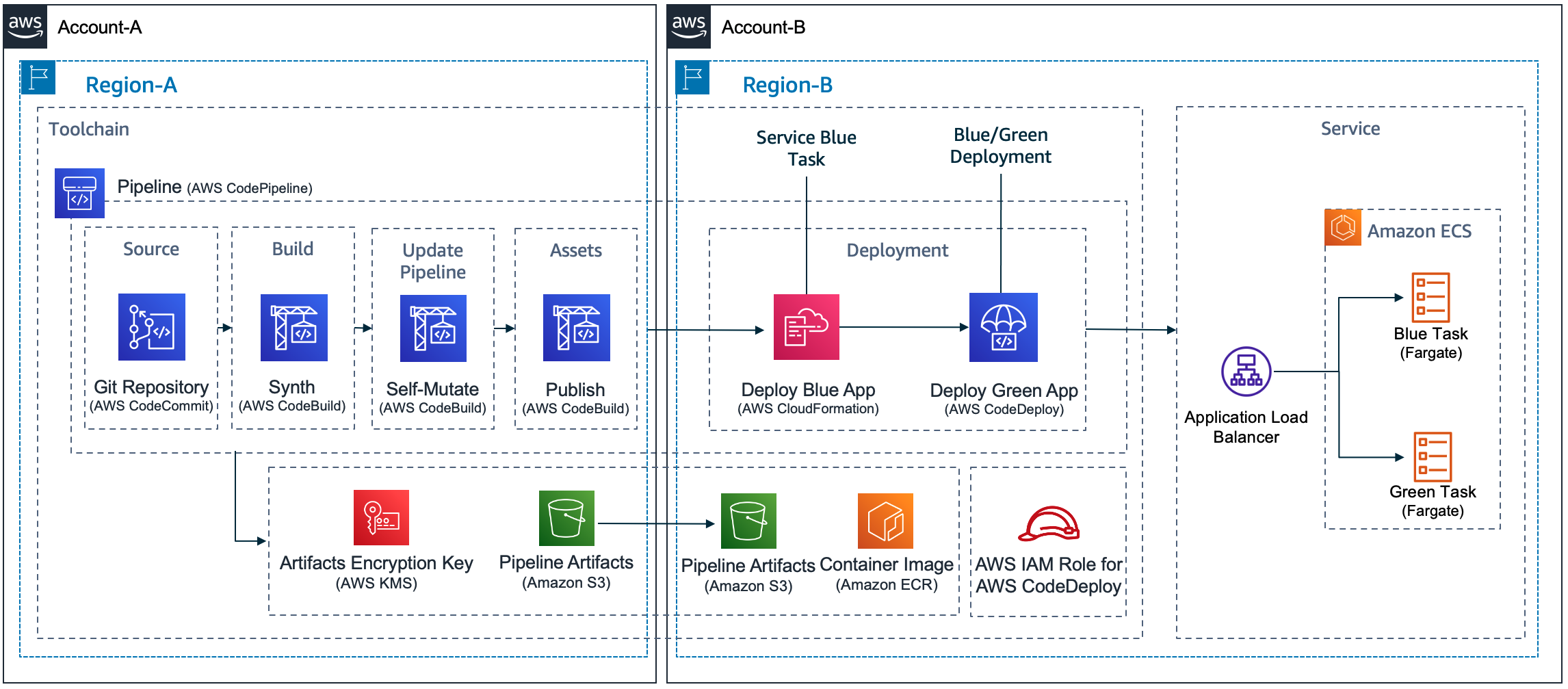
A pipeline build with CDK Pipelines that deploys to Amazon ECS using AWS CodeDeploy. It contains at least 5 stages: Source, Build, UpdatePipeline, Assets and at least one Deployment stage.

Design Considerations

In this post, I’m considering the use of CDK Pipelines to implement different use cases for deploying a service to any combination of accounts (single-account & cross-account) and regions (single-Region & cross-Region) using CodeDeploy. More specifically, there are four problems that need to be solved:

CodeDeploy Configuration

The most popular options for implementing a Blue/Green deployment type using CodeDeploy are using CloudFormation Hooks or using a CodeDeploy construct. I decided to operate CodeDeploy using its configuration files. This is a flexible design that doesn’t rely on using custom resources, which is another technique customers have used to solve this problem. On each run, a pipeline pushes a container to a repository on Amazon Elastic Container Registry (ECR) and creates a tag. CodeDeploy needs that information to deploy the container.

I recommend creating a pipeline action to scan the AWS CDK cloud assembly and retrieve the repository and tag information. The same action can create the CodeDeploy configuration files. Three configuration files are required to configure CodeDeploy: appspec.yaml, taskdef.json and imageDetail.json. This pipeline action should be executed before the CodeDeploy deployment action. I recommend creating template files for appspec.yaml and taskdef.json. The following script can be used to implement the pipeline action:

##
#!/bin/sh
#
# Action Configure AWS CodeDeploy
# It customizes the files template-appspec.yaml and template-taskdef.json to the environment
#
# Account = The target Account Id
# AppName = Name of the application
# StageName = Name of the stage
# Region = Name of the region (us-east-1, us-east-2)
# PipelineId = Id of the pipeline
# ServiceName = Name of the service. It will be used to define the role and the task definition name
#
# Primary output directory is codedeploy/. All the 3 files created (appspec.json, imageDetail.json and 
# taskDef.json) will be located inside the codedeploy/ directory
#
##
Account=$1
Region=$2
AppName=$3
StageName=$4
PipelineId=$5
ServiceName=$6
repo_name=$(cat assembly*$PipelineId-$StageName/*.assets.json | jq -r '.dockerImages[] | .destinations[] | .repositoryName' | head -1) 
tag_name=$(cat assembly*$PipelineId-$StageName/*.assets.json | jq -r '.dockerImages | to_entries[0].key')  
echo ${repo_name} 
echo ${tag_name} 
printf '{"ImageURI":"%s"}' "$Account.dkr.ecr.$Region.amazonaws.com/${repo_name}:${tag_name}" > codedeploy/imageDetail.json                     
sed 's#APPLICATION#'$AppName'#g' codedeploy/template-appspec.yaml > codedeploy/appspec.yaml 
sed 's#APPLICATION#'$AppName'#g' codedeploy/template-taskdef.json | sed 's#TASK_EXEC_ROLE#arn:aws:iam::'$Account':role/'$ServiceName'#g' | sed 's#fargate-task-definition#'$ServiceName'#g' > codedeploy/taskdef.json 
cat codedeploy/appspec.yaml
cat codedeploy/taskdef.json
cat codedeploy/imageDetail.json

Using a Toolchain

A good strategy is to encapsulate the pipeline inside a Toolchain to abstract how to deploy to different accounts and regions. This helps decoupling clients from the details such as how the pipeline is created, how CodeDeploy is configured, and how cross-account and cross-Region deployments are implemented. To create the pipeline, deploy a Toolchain stack. Out-of-the-box, it allows different environments to be added as needed. Depending on the requirements, the pipeline may be customized to reflect the different stages or waves that different components might require. For more information, please refer to our best practices on how to automate safe, hands-off deployments and its reference implementation.

In detail, the Toolchain stack follows the builder pattern used throughout the CDK for Java. This is a convenience that allows complex objects to be created using a single statement:

 Toolchain.Builder.create(app, Constants.APP_NAME+"Toolchain")
        .stackProperties(StackProps.builder()
                .env(Environment.builder()
                        .account(Demo.TOOLCHAIN_ACCOUNT)
                        .region(Demo.TOOLCHAIN_REGION)
                        .build())
                .build())
        .setGitRepo(Demo.CODECOMMIT_REPO)
        .setGitBranch(Demo.CODECOMMIT_BRANCH)
        .addStage(
                "UAT",
                EcsDeploymentConfig.CANARY_10_PERCENT_5_MINUTES,
                Environment.builder()
                        .account(Demo.SERVICE_ACCOUNT)
                        .region(Demo.SERVICE_REGION)
                        .build())                                                                                                             
        .build();

In the statement above, the continuous deployment pipeline is created in the TOOLCHAIN_ACCOUNT and TOOLCHAIN_REGION. It implements a stage that builds the source code and creates the Java archive (JAR) using Apache Maven.  The pipeline then creates a Docker image containing the JAR file.

The UAT stage will deploy the service to the SERVICE_ACCOUNT and SERVICE_REGION using the deployment configuration CANARY_10_PERCENT_5_MINUTES. This means 10 percent of the traffic is shifted in the first increment and the remaining 90 percent is deployed 5 minutes later.

To create additional deployment stages, you need a stage name, a CodeDeploy deployment configuration and an environment where it should deploy the service. As mentioned, the pipeline is, by default, a self-mutating pipeline. For example, to add a Prod stage, update the code that creates the Toolchain object and submit this change to the code repository. The pipeline will run and update itself adding a Prod stage after the UAT stage. Next, I show in detail the statement used to add a new Prod stage. The new stage deploys to the same account and Region as in the UAT environment:

... 
        .addStage(
                "Prod",
                EcsDeploymentConfig.CANARY_10_PERCENT_5_MINUTES,
                Environment.builder()
                        .account(Demo.SERVICE_ACCOUNT)
                        .region(Demo.SERVICE_REGION)
                        .build())                                                                                                                                      
        .build();

In the statement above, the Prod stage will deploy new versions of the service using a CodeDeploy deployment configuration CANARY_10_PERCENT_5_MINUTES. It means that 10 percent of traffic is shifted in the first increment of 5 minutes. Then, it shifts the rest of the traffic to the new version of the application. Please refer to Organizing Your AWS Environment Using Multiple Accounts whitepaper for best-practices on how to isolate and manage your business applications.

Some customers might find this approach interesting and decide to provide this as an abstraction to their application development teams. In this case, I advise creating a construct that builds such a pipeline. Using a construct would allow for further customization. Examples are stages that promote quality assurance or deploy the service in a disaster recovery scenario.

The implementation creates a stack for the toolchain and another stack for each deployment stage. As an example, consider a toolchain created with a single deployment stage named UAT. After running successfully, the DemoToolchain and DemoService-UAT stacks should be created as in the next image:

Two stacks are needed to create a Pipeline that deploys to a single environment. One stack deploys the Toolchain with the Pipeline and another stack deploys the Service compute infrastructure and CodeDeploy Application and DeploymentGroup. In this example, for an application named Demo that deploys to an environment named UAT, the stacks deployed are: DemoToolchain and DemoService-UAT

CodeDeploy Application and Deployment Group

CodeDeploy configuration requires an application and a deployment group. Depending on the use case, you need to create these in the same or in a different account from the toolchain (pipeline). The pipeline includes the CodeDeploy deployment action that performs the blue/green deployment. My recommendation is to create the CodeDeploy application and deployment group as part of the Service stack. This approach allows to align the lifecycle of CodeDeploy application and deployment group with the related Service stack instance.

CodePipeline allows to create a CodeDeploy deployment action that references a non-existing CodeDeploy application and deployment group. This allows us to implement the following approach:

  • Toolchain stack deploys the pipeline with CodeDeploy deployment action referencing a non-existing CodeDeploy application and deployment group
  • When the pipeline executes, it first deploys the Service stack that creates the related CodeDeploy application and deployment group
  • The next pipeline action executes the CodeDeploy deployment action. When the pipeline executes the CodeDeploy deployment action, the related CodeDeploy application and deployment will already exist.

Below is the pipeline code that references the (initially non-existing) CodeDeploy application and deployment group.

private IEcsDeploymentGroup referenceCodeDeployDeploymentGroup(
        final Environment env, 
        final String serviceName, 
        final IEcsDeploymentConfig ecsDeploymentConfig, 
        final String stageName) {

    IEcsApplication codeDeployApp = EcsApplication.fromEcsApplicationArn(
            this,
            Constants.APP_NAME + "EcsCodeDeployApp-"+stageName,
            Arn.format(ArnComponents.builder()
                    .arnFormat(ArnFormat.COLON_RESOURCE_NAME)
                    .partition("aws")
                    .region(env.getRegion())
                    .service("codedeploy")
                    .account(env.getAccount())
                    .resource("application")
                    .resourceName(serviceName)
                    .build()));

    IEcsDeploymentGroup deploymentGroup = EcsDeploymentGroup.fromEcsDeploymentGroupAttributes(
            this,
            Constants.APP_NAME + "-EcsCodeDeployDG-"+stageName,
            EcsDeploymentGroupAttributes.builder()
                    .deploymentGroupName(serviceName)
                    .application(codeDeployApp)
                    .deploymentConfig(ecsDeploymentConfig)
                    .build());

    return deploymentGroup;
}

To make this work, you should use the same application name and deployment group name values when creating the CodeDeploy deployment action in the pipeline and when creating the CodeDeploy application and deployment group in the Service stack (where the Amazon ECS infrastructure is deployed). This approach is necessary to avoid a circular dependency error when trying to create the CodeDeploy application and deployment group inside the Service stack and reference these objects to configure the CodeDeploy deployment action inside the pipeline. Below is the code that uses Service stack construct ID to name the CodeDeploy application and deployment group. I set the Service stack construct ID to the same name I used when creating the CodeDeploy deployment action in the pipeline.

   // configure AWS CodeDeploy Application and DeploymentGroup
   EcsApplication app = EcsApplication.Builder.create(this, "BlueGreenApplication")
           .applicationName(id)
           .build();

   EcsDeploymentGroup.Builder.create(this, "BlueGreenDeploymentGroup")
           .deploymentGroupName(id)
           .application(app)
           .service(albService.getService())
           .role(createCodeDeployExecutionRole(id))
           .blueGreenDeploymentConfig(EcsBlueGreenDeploymentConfig.builder()
                   .blueTargetGroup(albService.getTargetGroup())
                   .greenTargetGroup(tgGreen)
                   .listener(albService.getListener())
                   .testListener(listenerGreen)
                   .terminationWaitTime(Duration.minutes(15))
                   .build())
           .deploymentConfig(deploymentConfig)
           .build();

CDK Pipelines roles and permissions

CDK Pipelines creates roles and permissions the pipeline uses to execute deployments in different scenarios of regions and accounts. When using CodeDeploy in cross-account scenarios, CDK Pipelines deploys a cross-account support stack that creates a pipeline action role for the CodeDeploy action. This cross-account support stack is defined in a JSON file that needs to be published to the AWS CDK assets bucket in the target account. If the pipeline has the self-mutation feature on (default), the UpdatePipeline stage will do a cdk deploy to deploy changes to the pipeline. In cross-account scenarios, this deployment also involves deploying/updating the cross-account support stack. For this, the SelfMutate action in UpdatePipeline stage needs to assume CDK file-publishing and a deploy roles in the remote account.

The IAM role associated with the AWS CodeBuild project that runs the UpdatePipeline stage does not have these permissions by default. CDK Pipelines cannot grant these permissions automatically, because the information about the permissions that the cross-account stack needs is only available after the AWS CDK app finishes synthesizing. At that point, the permissions that the pipeline has are already locked-in­­. Hence, for cross-account scenarios, the toolchain should extend the permissions of the pipeline’s UpdatePipeline stage to include the file-publishing and deploy roles.

In cross-account environments it is possible to manually add these permissions to the UpdatePipeline stage. To accomplish that, the Toolchain stack may be used to hide this sort of implementation detail. In the end, a method like the one below can be used to add these missing permissions. For each different mapping of stage and environment in the pipeline it validates if the target account is different than the account where the pipeline is deployed. When the criteria is met, it should grant permission to the UpdatePipeline stage to assume CDK bootstrap roles (tagged using key aws-cdk:bootstrap-role) in the target account (with the tag value as file-publishing or deploy). The example below shows how to add permissions to the UpdatePipeline stage:

private void grantUpdatePipelineCrossAccoutPermissions(Map<String, Environment> stageNameEnvironment) {

    if (!stageNameEnvironment.isEmpty()) {

        this.pipeline.buildPipeline();
        for (String stage : stageNameEnvironment.keySet()) {

            HashMap<String, String[]> condition = new HashMap<>();
            condition.put(
                    "iam:ResourceTag/aws-cdk:bootstrap-role",
                    new String[] {"file-publishing", "deploy"});
            pipeline.getSelfMutationProject()
                    .getRole()
                    .addToPrincipalPolicy(PolicyStatement.Builder.create()
                            .actions(Arrays.asList("sts:AssumeRole"))
                            .effect(Effect.ALLOW)
                            .resources(Arrays.asList("arn:*:iam::"
                                    + stageNameEnvironment.get(stage).getAccount() + ":role/*"))
                            .conditions(new HashMap<String, Object>() {{
                                    put("ForAnyValue:StringEquals", condition);
                            }})
                            .build());
        }
    }
}

The Deployment Stage

Let’s consider a pipeline that has a single deployment stage, UAT. The UAT stage deploys a DemoService. For that, it requires four actions: DemoService-UAT (Prepare and Deploy), ConfigureBlueGreenDeploy and Deploy.

When using CodeDeploy the deployment stage is expected to have four actions: two actions to create CloudFormation change set and deploy the ECS or compute infrastructure, an action to configure CodeDeploy and the last action that deploys the application using CodeDeploy. In the diagram, these are (in the diagram in the respective order): DemoService-UAT.Prepare and DemoService-UAT.Deploy, ConfigureBlueGreenDeploy and Deploy.

The
DemoService-UAT.Deploy action will create the ECS resources and the CodeDeploy application and deployment group. The
ConfigureBlueGreenDeploy action will read the AWS CDK
cloud assembly. It uses the configuration files to identify the Amazon Elastic Container Registry (Amazon ECR) repository and the container image tag pushed. The pipeline will send this information to the
Deploy action.  The
Deploy action starts the deployment using CodeDeploy.

Solution Overview

As a convenience, I created an application, written in Java, that solves all these challenges and can be used as an example. The application deployment follows the same 5 steps for all deployment scenarios of account and Region, and this includes the scenarios represented in the following design:

A pipeline created by a Toolchain should be able to deploy to any combination of accounts and regions. This includes four scenarios: single-account and single-Region, single-account and cross-Region, cross-account and single-Region and cross-account and cross-Region

Conclusion

In this post, I identified, explained and solved challenges associated with the creation of a pipeline that deploys a service to Amazon ECS using CodeDeploy in different combinations of accounts and regions. I also introduced a demo application that implements these recommendations. The sample code can be extended to implement more elaborate scenarios. These scenarios might include automated testing, automated deployment rollbacks, or disaster recovery. I wish you success in your transformative journey.

Luiz Decaro

Luiz is a Principal Solutions architect at Amazon Web Services (AWS). He focuses on helping customers from the Financial Services Industry succeed in the cloud. Luiz holds a master’s in software engineering and he triggered his first continuous deployment pipeline in 2005.

Understanding the lifecycle of Amazon EC2 Dedicated Hosts

Post Syndicated from Sheila Busser original https://aws.amazon.com/blogs/compute/understanding-the-lifecycle-of-amazon-ec2-dedicated-hosts/

This post is written by Benjamin Meyer, Sr. Solutions Architect, and Pascal Vogel, Associate Solutions Architect.

Amazon Elastic Compute Cloud (Amazon EC2) Dedicated Hosts enable you to run software on dedicated physical servers. This lets you comply with corporate compliance requirements or per-socket, per-core, or per-VM licensing agreements by vendors, such as Microsoft, Oracle, and Red Hat. Dedicated Hosts are also required to run Amazon EC2 Mac Instances.

The lifecycles and states of Amazon EC2 Dedicated Hosts and Amazon EC2 instances are closely connected and dependent on each other. To operate Dedicated Hosts correctly and consistently, it is critical to understand the interplay between Dedicated Hosts and EC2 Instances. In this post, you’ll learn how EC2 instances are reliant on their (dedicated) hosts. We’ll also dive deep into their respective lifecycles, the connection points of these lifecycles, and the resulting considerations.

What is an EC2 instance?

An EC2 instance is a virtual server running on top of a physical Amazon EC2 host. EC2 instances are launched using a preconfigured template called Amazon Machine Image (AMI), which packages the information required to launch an instance. EC2 instances come in various CPU, memory, storage and GPU configurations, known as instance types, to enable you to choose the right instance for your workload. The process of finding the right instance size is known as right sizing. Amazon EC2 builds on the AWS Nitro System, which is a combination of dedicated hardware and the lightweight Nitro hypervisor. The EC2 instances that you launch in your AWS Management Console via Launch Instances are launched on AWS-controlled physical hosts.

What is an Amazon EC2 Bare Metal instance?

Bare Metal instances are instances that aren’t using the Nitro hypervisor. Bare Metal instances provide direct access to physical server hardware. Therefore, they let you run legacy workloads that don’t support a virtual environment, license-restricted business-critical applications, or even your own hypervisor. Workloads on Bare Metal instances continue to utilize AWS Cloud features, such as Amazon Elastic Block Store (Amazon EBS), Elastic Load Balancing (ELB), and Amazon Virtual Private Cloud (Amazon VPC).

What is an Amazon EC2 Dedicated Host?

An Amazon EC2 Dedicated Host is a physical server fully dedicated to a single customer. With visibility of sockets and physical cores of the Dedicated Host, you can address corporate compliance requirements, such as per-socket, per-core, or per-VM software licensing agreements.

You can launch EC2 instances onto a Dedicated Host. Instance families such as M5, C5, R5, M5n, C5n, and R5n allow for the launching of different instance sizes, such as4xlarge and 8xlarge, to the same host. Other instance families only support a homogenous launching of a single instance size. For more details, see Dedicated Host instance capacity.

As an example, let’s look at an M6i Dedicated Host. M6i Dedicated Hosts have 2 sockets and 64 physical cores. If you allocate a M6i Dedicated Host, then you can specify what instance type you’d like to support for allocation. In this case, possible instance sizes are:

  • large
  • xlarge
  • 2xlarge
  • 4xlarge
  • 8xlarge
  • 12xlarge
  • 16xlarge
  • 24xlarge
  • 32xlarge
  • metal

The number of instances that you can launch on a single M6i Dedicated Host depends on the selected instance size. For example:

  • In the case of xlarge (4 vCPUs), a maximum of 32 m6i.xlarge instances can be scheduled on this Dedicated Host.
  • In the case of 8xlarge (32 vCPUs), a maximum of 4 m6i.8xlarge instances can be scheduled on this Dedicated Host.
  • In the case of metal (128 vCPUs), a maximum of 1 m6i.metal instance can be scheduled on this Dedicated Host.

When launching an EC2 instance on a Dedicated Host, you’re billed for the Dedicated Host but not for the instance. The cost for Amazon EBS volumes is the same as in the case of regular EC2 instances.

Exemplary homogenious M6i Dedicated Host shown with 32 m6i.xlarge, four m6i.8xlarge and one m6i.metal each.

Exemplary M6i Dedicated Host instance selections: m6i.xlarge, m6i.8xlarge and m6i.metal

Understanding the EC2 instance lifecycle

Amazon EC2 instance lifecycle states and transitions

Throughout its lifecycle, an EC2 instance transitions through different states, starting with its launch and ending with its termination. Upon Launch, an EC2 instance enters the pending state. You can only launch EC2 instances on Dedicated Hosts in the available state. You aren’t billed for the time that the EC2 instance is in any state other than running. When launching an EC2 instance on a Dedicated Host, you’re billed for the Dedicated Host but not for the instance. Depending on the user action, the instance can transition into three different states from the running state:

  1. Via Reboot from the running state, the instance enters the rebooting state. Once the reboot is complete, it reenters the running state.
  2. In the case of an Amazon EBS-backed instance, a Stop or Stop-Hibernate transitions the running instance into the stopping state. After reaching the stopped state, it remains there until further action is taken. Via Start, the instance will reenter the pending and subsequently the running state. Via Terminate from the stopped state, the instance will enter the terminated state. As part of a Stop or Stop-Hibernate and subsequent Start, the EC2 instance may move to a different AWS-managed host. On Reboot, it remains on the same AWS-managed host.
  3. Via Terminate from the running state, the instance will enter the shutting-down state, and finally the terminated state. An instance can’t be started from the terminated state.

Understanding the Amazon EC2 Dedicated Host lifecycle

A diagram of the the Amazon EC2 Dedicated Host lifecycle states and transitions between them.

Amazon EC2 Dedicated Host lifecycle states and transitions

An Amazon EC2 Dedicated Host enters the available state as soon as you allocate it in your AWS account. Only if the Dedicated Host is in the available state, you can launch EC2 instances on it. You aren’t billed for the time that your Dedicated Host is in any state other than available. From the available state, the following states and state transitions can be reached:

  1. You can Release the Dedicated Host, transitioning it into the released state. Amazon EC2 Mac Instances Dedicated Hosts have a minimum allocation time of 24h. They can’t be released within the 24h. You can’t release a Dedicated Host that contains instances in one of the following states: pending, running, rebooting, stopping, or shutting down. Consequently, you must Stop or Terminate any EC2 instances on the Dedicated Host and wait until it’s in the available state before being able to release it. Once an instance is in the stopped state, you can move it to a different Dedicated Host by modifying its Instance placement configuration.
  2. The Dedicated Host may enter the pending state due to a number of reasons. In case of an EC2 Mac instance, stopping or terminating a Mac instance initiates a scrubbing workflow of the underlying Dedicated Host, during which it enters the pending state. This scrubbing workflow includes tasks such as erasing the internal SSD, resetting NVRAM, and more, and it can take up to 50 minutes to complete. Additionally, adding or removing a Dedicated Host to or from a Resource Group can cause the Dedicated Host to go into the pending state. From the pending state, the Dedicated Host will reenter the available state.
  3. The Dedicated Host may enter the under-assessment state if AWS is investigating a possible issue with the underlying infrastructure, such as a hardware defect or network connectivity event. While the host is in the under-assessment state, all of the EC2 instances running on it will have the impaired status. Depending on the nature of the underlying issue and if it’s configured, the Dedicated Host will initiate host auto recovery.

If Dedicated Host Auto Recovery is enabled for your host, then AWS attempts to restart the instances currently running on a defect Dedicated Host on an automatically allocated replacement Dedicated Host without requiring your manual intervention. When host recovery is initiated, the AWS account owner is notified by email and by an AWS Health Dashboard event. A second notification is sent after the host recovery has been successfully completed. Initially, the replacement Dedicated Host is in the pending state. EC2 instances running on the defect dedicated Host remain in the impaired status throughout this process. For more information, see the Host Recovery documentation.

Once all of the EC2 instances have been successfully relaunched on the replacement Dedicated Host, it enters the available state. Recovered instances reenter the running state. The original Dedicated Host enters the released-permanent-failure state. However, if the EC2 instances running on the Dedicated Host don’t support host recovery, then the original Dedicated Host enters the permanent-failure state instead.

Conclusion

In this post, we’ve explored the lifecycles of Amazon EC2 instances and Amazon EC2 Dedicated Hosts. We took a close look at the individual lifecycle states and how both lifecycles must be considered in unison to operate EC2 Instances on EC2 Dedicated Hosts correctly and consistently. To learn more about operating Amazon EC2 Dedicated Hosts, visit the EC2 Dedicated Hosts User Guide.

Making your Go workloads up to 20% faster with Go 1.18 and AWS Graviton

Post Syndicated from Sheila Busser original https://aws.amazon.com/blogs/compute/making-your-go-workloads-up-to-20-faster-with-go-1-18-and-aws-graviton/

This blog post was written by Syl Taylor, Professional Services Consultant.

In March 2022, the highly anticipated Go 1.18 was released. Go 1.18 brings to the language some long-awaited features and additions, such as generics. It also brings significant performance improvements for Arm’s 64-bit architecture used in AWS Graviton server processors. In this post, we show how migrating Go workloads from Go 1.17.8 to Go 1.18 can help you run your applications up to 20% faster and more cost-effectively. To achieve this goal, we selected a series of realistic and relatable workloads to showcase how they perform when compiled with Go 1.18.

Overview

Go is an open-source programming language which can be used to create a wide range of applications. It’s developer-friendly and suitable for designing production-grade workloads in areas such as web development, distributed systems, and cloud-native software.

AWS Graviton2 processors are custom-built by AWS using 64-bit Arm Neoverse cores to deliver the best price-performance for your cloud workloads running in Amazon Elastic Compute Cloud (Amazon EC2). They provide up to 40% better price/performance over comparable x86-based instances for a wide variety of workloads and they can run numerous applications, including those written in Go.

Web service throughput

For web applications, the number of HTTP requests that a server can process in a window of time is an important measurement to determine scalability needs and reduce costs.

To demonstrate the performance improvements for a Go-based web service, we selected the popular Caddy web server. To perform the load testing, we selected the hey application, which was also written in Go. We deployed these packages in a client/server scenario on m6g Graviton instances.

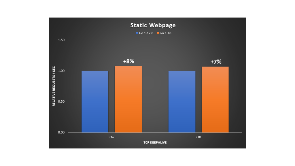
Relative performance comparison for requesting a static webpage

The Caddy web server compiled with Go 1.18 brings a 7-8% throughput improvement as compared with the variant compiled with Go 1.17.8.

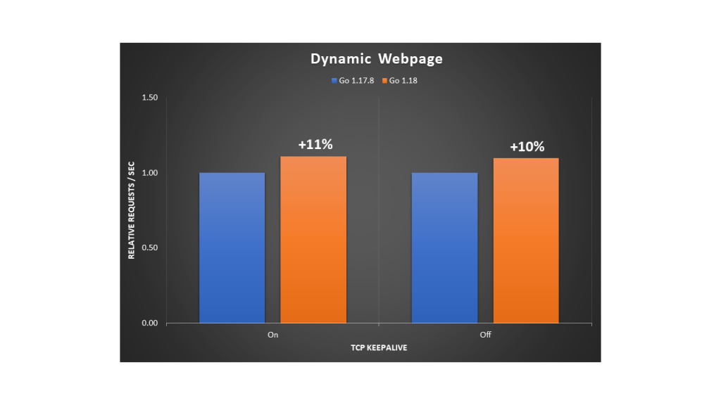
We conducted a second test where the client downloads a dynamic page on which the request handler performs some additional processing to write the HTTP response content. The performance gains were also noticeable at 10-11%.

Relative performance comparison for requesting a dynamic webpage

Regular expression searches

Searching through large amounts of text is where regular expression patterns excel. They can be used for many use cases, such as:

  • Checking if a string has a valid format (e.g., email address, domain name, IP address),
  • Finding all of the occurrences of a string (e.g., date) in a text document,
  • Identifying a string and replacing it with another.

However, despite their efficiency in search engines, text editors, or log parsers, regular expression evaluation is an expensive operation to run. We recommend identifying optimizations to reduce search time and compute costs.

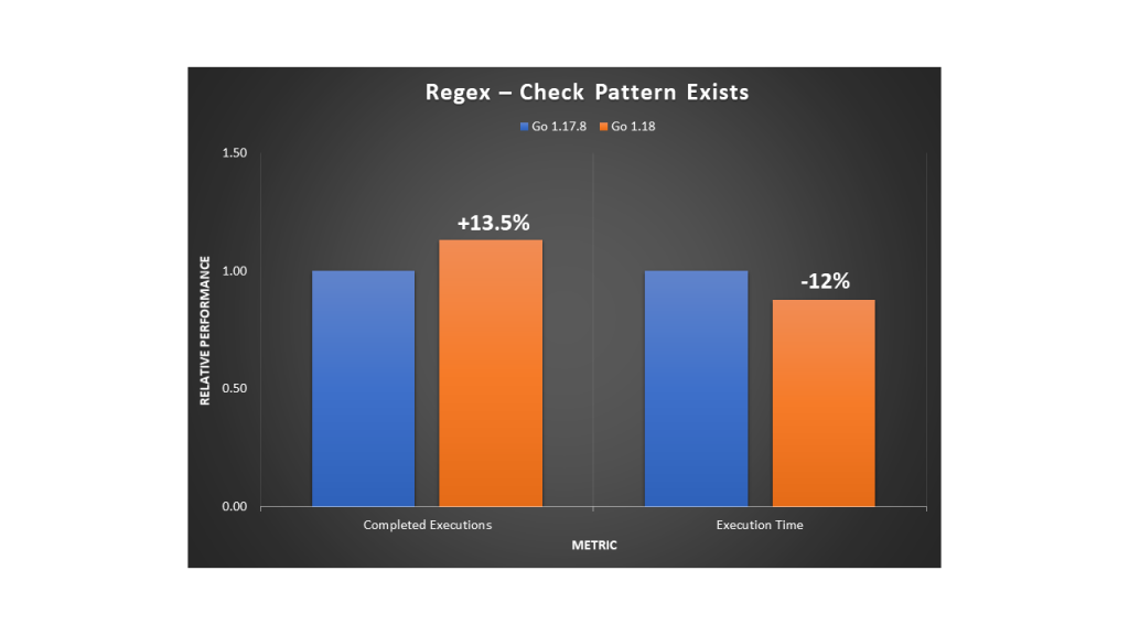
The following example uses the Go regexp package to compile a pattern and search for the presence of a standard date format in a large generated string. We observed a 13.5% increase in completed executions with a 12% reduction in execution time.

Relative performance comparison for using regular expressions to check that a pattern exists

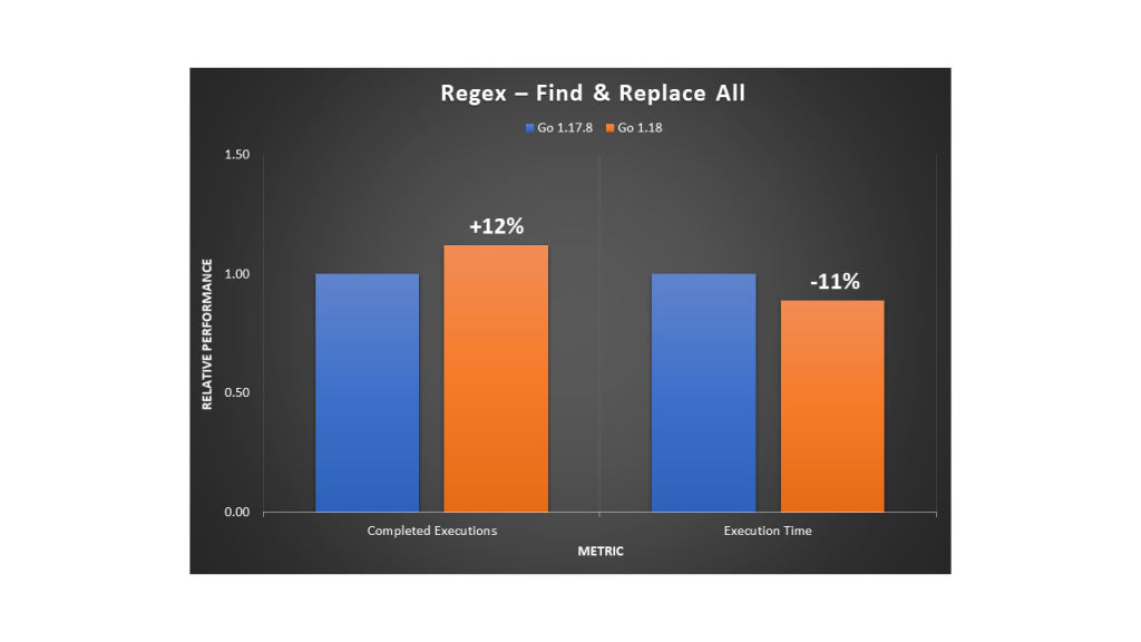
In a second example, we used the Go regexp package to find all of the occurrences of a pattern for character sequences in a string, and then replace them with a single character. We observed a 12% increase in evaluation rate with an 11% reduction in execution time.

Relative performance comparison for using regular expressions to find and replace all of the occurrences of a pattern

As with most workloads, the improvements will vary depending on the input data, the hardware selected, and the software stack installed. Furthermore, with this use case, the regular expression usage will have an impact on the overall performance. Given the importance of regex patterns in modern applications, as well as the scale at which they’re used, we recommend upgrading to Go 1.18 for any software that relies heavily on regular expression operations.

Database storage engines

Many database storage engines use a key-value store design to benefit from simplicity of use, faster speed, and improved horizontal scalability. Two implementations commonly used are B-trees and LSM (log-structured merge) trees. In the age of cloud technology, building distributed applications that leverage a suitable database service is important to make sure that you maximize your business outcomes.

B-trees are seen in many database management systems (DBMS), and they’re used to efficiently perform queries using indexes. When we tested a sample program for inserting and deleting in a large B-tree structure, we observed a 10.5% throughput increase with a 10% reduction in execution time.

Relative performance comparison for inserting and deleting in a B-Tree structure

On the other hand, LSM trees can achieve high rates of write throughput, thus making them useful for big data or time series events, such as metrics and real-time analytics. They’re used in modern applications due to their ability to handle large write workloads in a time of rapid data growth. The following are examples of databases that use LSM trees:

  • InfluxDB is a powerful database used for high-speed read and writes on time series data. It’s written in Go and its storage engine uses a variation of LSM called the Time-Structured Merge Tree (TSM).
  • CockroachDB is a popular distributed SQL database written in Go with its own LSM tree implementation.
  • Badger is written in Go and is the engine behind Dgraph, a graph database. Its design leverages LSM trees.

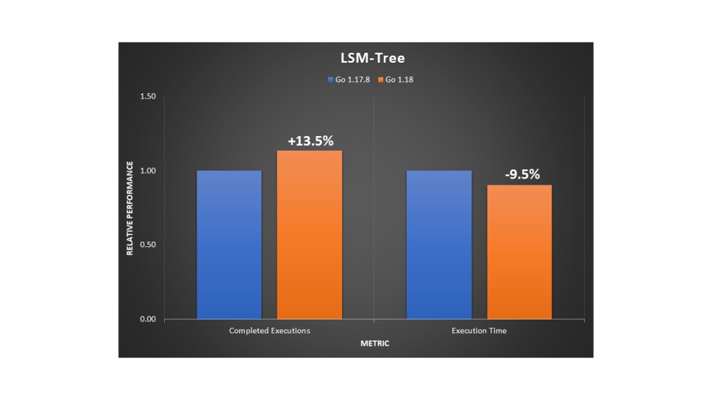
When we tested an LSM tree sample program, we observed a 13.5% throughput increase with a 9.5% reduction in execution time.

We also tested InfluxDB using comparison benchmarks to analyze writes and reads to the database server. On the load stress test, we saw a 10% increase of insertion throughput and a 14.5% faster rate when querying at a large scale.

Relative performance comparison for inserting to and querying from an InfluxDB database

In summary, for databases with an engine written in Go, you’ll likely observe better performance when upgrading to a version that has been compiled with Go 1.18.

Machine learning training

A popular unsupervised machine learning (ML) algorithm is K-Means clustering. It aims to group similar data points into k clusters. We used a dataset of 2D coordinates to train K-Means and obtain the cluster distribution in a deterministic manner. The example program uses an OOP design. We noticed an 18% improvement in execution throughput and a 15% reduction in execution time.

Relative performance comparison for training a K-means model

A widely-used and supervised ML algorithm for both classification and regression is Random Forest. It’s composed of numerous individual decision trees, and it uses a voting mechanism to determine which prediction to use. It’s a powerful method for optimizing ML models.

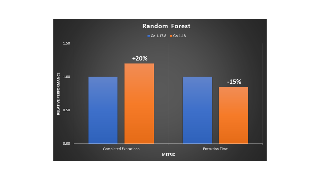
We ran a deterministic example to train a dense Random Forest. The program uses an OOP design and we noted a 20% improvement in execution throughput and a 15% reduction in execution time.

Relative performance comparison for training a Random Forest model

Recursion

An efficient, general-purpose method for sorting data is the merge sort algorithm. It works by repeatedly breaking down the data into parts until it can compare single units to each other. Then, it decides their order in the intermediary steps that will merge repeatedly until the final sorted result. To implement this divide-and-conquer approach, merge sort must use recursion. We ran the program using a large dataset of numbers and observed a 7% improvement in execution throughput and a 4.5% reduction in execution time.

Relative performance comparison for running a merge sort algorithm

Depth-first search (DFS) is a fundamental recursive algorithm for traversing tree or graph data structures. Many complex applications rely on DFS variants to solve or optimize hard problems in various areas, such as path finding, scheduling, or circuit design. We implemented a standard DFS traversal in a fully-connected graph. Then we observed a 14.5% improvement in execution throughput and a 13% reduction in execution time.

Relative performance comparison for running a DFS algorithm

Conclusion

In this post, we’ve shown that a variety of applications, not just those primarily compute-bound, can benefit from the 64-bit Arm CPU performance improvements released in Go 1.18. Programs with an object-oriented design, recursion, or that have many function calls in their implementation will likely benefit more from the new register ABI calling convention.

By using AWS Graviton EC2 instances, you can benefit from up to a 40% price/performance improvement over other instance types. Furthermore, you can save even more with Graviton through the additional performance improvements by simply recompiling your Go applications with Go 1.18.

To learn more about Graviton, see the Getting started with AWS Graviton guide.

Control access to Amazon Elastic Container Service resources by using ABAC policies

Post Syndicated from Kriti Heda original https://aws.amazon.com/blogs/security/control-access-to-amazon-elastic-container-service-resources-by-using-abac-policies/

As an AWS customer, if you use multiple Amazon Elastic Container Service (Amazon ECS) services/tasks to achieve better isolation, you often have the challenge of how to manage access to these containers. In such cases, using tags can enable you to categorize these services in different ways, such as by owner or environment.

This blog post shows you how tags allow conditional access to Amazon ECS resources. You can use attribute-based access control (ABAC) policies to grant access rights to users through the use of policies that combine attributes together. ABAC can be helpful in rapidly-growing environments, where policy management can become cumbersome. This blog post uses ECS resource tags (owner tag and environment tag) as the attributes that are used to control access in the policies.

Amazon ECS resources have many attributes, such as tags, which can be used to control permissions. You can attach tags to AWS Identity and Access Management (IAM) principals, and create either a single ABAC policy, or a small set of policies for your IAM principals. These ABAC policies can be designed to allow operations when the principal tag (a tag that exists on the user or role making the call) matches the resource tag. They can be used to simplify permission management at scale. A single Amazon ECS policy can enforce permissions across a range of applications, without having to update the policy each time you create new Amazon ECS resources.

This post provides a step-by-step procedure for creating ABAC policies for controlling access to Amazon ECS containers. As the team adds ECS resources to its projects, permissions are automatically applied based on the owner tag and the environment tag. As a result, no policy update is required for each new resource. Using this approach can save time and help improve security, because it relies on granular permissions rules.

Condition key mappings

It’s important to note that each IAM permission in Amazon ECS supports different types of tagging condition keys. The following table maps each condition key to its ECS actions.

Condition key Description ECS actions
aws:RequestTag/${TagKey} Set this tag value to require that a specific tag be used (or not used) when making an API request to create or modify a resource that allows tags. ecs:CreateCluster,
ecs:TagResource,
ecs:CreateCapacityProvider
aws:ResourceTag/${TagKey} Set this tag value to allow or deny user actions on resources with specific tags. ecs:PutAttributes,
ecs:StopTask,
ecs:DeleteCluster,
ecs:DeleteService,
ecs:CreateTaskSet,
ecs:DeleteAttributes,
ecs:DeleteTaskSet,
ecs:DeregisterContainerInstance
aws:RequestTag/${TagKey}
and
aws:ResourceTag/${TagKey}
Supports both RequestTag and ResourceTag ecs:CreateService,
ecs:RunTask,
ecs:StartTask,
ecs:RegisterContainerInstance

For a detailed guide of Amazon ECS actions and the resource types and condition keys they support, see Actions, resources, and condition keys for Amazon Elastic Container Service.

Tutorial overview

The following tutorial gives you a step-by-step process to create and test an Amazon ECS policy that allows IAM roles with principal tags to access resources with matching tags. When a principal makes a request to AWS, their permissions are granted based on whether the principal and resource tags match. This strategy allows individuals to view or edit only the ECS resources required for their jobs.

Scenario

Example Corp. has multiple Amazon ECS containers created for different applications. Each of these containers are created by different owners within the company. The permissions for each of the Amazon ECS resources must be restricted based on the owner of the container, and also based on the environment where the action is performed.

Assume that you’re a lead developer at this company, and you’re an experienced IAM administrator. You’re familiar with creating and managing IAM users, roles, and policies. You want to ensure that the development engineering team members can access only the containers they own. You also need a strategy that will scale as your company grows.

For this scenario, you choose to use AWS resource tags and IAM role principal tags to implement an ABAC strategy for Amazon ECS resources. The condition key mappings table shows which tagging condition keys you can use in a policy for each Amazon ECS action and resources. You can define the tags in the role you created. For this scenario, you define two tags Owner and Environment. These tags restrict permissions in the role based on the tags you defined.

Prerequisites

To perform the steps in this tutorial, you must already have the following:

  • An IAM role or user with sufficient privileges for services like IAM and ECS. Following the security best practices the role should have a minimum set of permissions and grant additional permissions as necessary. You can add the AWS managed policies IAMFullAccess and AmazonECS_FullAccess to create the IAM role to provide permissions for creating IAM and ECS resources.
  • An AWS account that you can sign in to as an IAM role or user.
  • Experience creating and editing IAM users, roles, and policies in the AWS Management Console. For more information, see Tutorial to create IAM resources.

Create an ABAC policy for Amazon ECS resources

After you complete the prerequisites for the tutorial, you will need to define which Amazon ECS privileges and access controls you want in place for the users, and configure the tags needed for creating the ABAC policies. This tutorial focuses on providing step-by-step instructions for creating test users, defining the ABAC policies for the Amazon ECS resources, creating a role, and defining tags for the implementation.

To create the ABAC policy

You create an ABAC policy that defines permissions based on attributes. In AWS, these attributes are called tags.

The sample ABAC policy that follows provides ECS permissions to users when the principal’s tag matches the resource tag.

Sample ABAC policy for ECS resources

The sample ECS ABAC policy that follows allows the user to perform action on the ECS resources, but only when those resources are tagged with the same key-pairs as the principal.

  1. Download the sample ECS policy. This policy allows principals to create, read, edit, and delete resources, but only when those resources are tagged with the same key-value pairs as the principal.
  2. Use the downloaded ECS policy to create the ECS ABAC policy, and name your new policy ECSABAC policy. For more information, see Creating IAM policies.

This sample policy provides permission to each ECS action based on the condition key that action supports. See to the condition key mappings table for a mapping of the ECS actions and the condition key they support.

What does this policy do?

  • The ECSCreateCluster statement allows users to create cluster, create and tag resources. These ECS actions only support the RequestTag condition key. This condition block returns true if every tag passed (tags: owner and environment) in the request is included in the specified list. This is done using the StringEquals condition operator. If an incorrect tag key other than owner or environment tag is passed, or incorrect value for the tags are passed, then the condition returns false. The ECS actions within these statements do not have a specific requirement of a resource type.
  • The ECSDeletion, ECSUpdate, and ECSDescribe statements allow users to update, delete or list/describe ECS resources. The ECS actions under these statements only support the ResourceTag condition key. Statements return true if the specified tag keys are present on the ECS resource and their values match the principal’s tags. These statements return false for mismatched tags (in this policy, the only acceptable tags are owner and environment), or for an incorrect value for the owner and environment tag passed to the ECS resources. They also return false for any ECS action that does not support resource tagging.
  • The ECSCreateService, ECSTaskControl, and ECSRegistration statements contain ECS actions that allow users to create a service, start or run tasks and register container instances in ECS. The ECS actions within these statements support both Request and Resource tag condition keys.

Create IAM roles

Create the following IAM roles and attach the ECSABAC policy you created in the previous procedure. You can create the roles and add tags to them using the AWS console, through the role creation flow, as shown in the following steps.

To create IAM roles

  1. Sign in to the AWS Management Console and navigate to the IAM console.
  2. In the left navigation pane, select Roles, and then select Create Role.
  3. Choose the Another AWS account role type.
  4. For Account ID, enter the AWS account ID mentioned in the prerequisites to which you want to grant access to your resources.
  5. Choose Next: Permissions.
  6. IAM includes a list of the AWS managed and customer managed policies in your account. Select the ECSABAC policy you created previously from the dropdown menu to use for the permissions policy. Alternatively, you can choose Create policy to open a new browser tab and create a new policy, as shown in Figure 1.
    Figure 1. Attach the ECS ABAC policy to the role

    Figure 1. Attach the ECS ABAC policy to the role

  7. Choose Next: Tags.
  8. Add metadata to the role by attaching tags as key-value pairs. Add the following tags to the role: for Key owner, enter Value mock_owner; and for Key environment, enter development, as shown in Figure 2.
    Figure 2. Define the tags in the IAM role

    Figure 2. Define the tags in the IAM role

  9. Choose Next: Review.
  10. For Role name, enter a name for your role. Role names must be unique within your AWS account.
  11. Review the role and then choose Create role.

Test the solution

The following sections present some positive and negative test cases that show how tags can provide fine-grained permission to users through ABAC policies.

Prerequisites for the negative and positive testing

Before you can perform the positive and negative tests, you must first do these steps in the AWS Management Console:

  1. Follow the procedures above for creating IAM role and the ABAC policy.
  2. Switch the role from the role assumed in the prerequisites to the role you created in To create IAM Roles above, following the steps in the documentation Switching to a role.

Perform negative testing

For the negative testing, three test cases are presented here that show how the ABAC policies prevent successful creation of the ECS resources if the owner or environment tags are missing, or if an incorrect tag is used for the creation of the ECS resource.

Negative test case 1: Create cluster without the required tags

In this test case, you check if an ECS cluster is successfully created without any tags. Create an Amazon ECS cluster without any tags (in other words, without adding the owner and environment tag).

To create a cluster without the required tags

  1. Sign in to the AWS Management Console and navigate to the IAM console.
  2. From the navigation bar, select the Region to use.
  3. In the navigation pane, choose Clusters.
  4. On the Clusters page, choose Create Cluster.
  5. For Select cluster compatibility, choose Networking only, then choose Next Step.
  6. On the Configure cluster page, enter a cluster name. For Provisioning Model, choose On-Demand Instance, as shown in Figure 3.
    Figure 3. Create a cluster

    Figure 3. Create a cluster

  7. In the Networking section, configure the VPC for your cluster.
  8. Don’t add any tags in the Tags section, as shown in Figure 4.
    Figure 4. No tags added to the cluster

    Figure 4. No tags added to the cluster

  9. Choose Create.

Expected result of negative test case 1

Because the owner and the environment tags are absent, the ABAC policy prevents the creation of the cluster and throws an error, as shown in Figure 5.

Figure 5. Unsuccessful creation of the ECS cluster due to missing tags

Figure 5. Unsuccessful creation of the ECS cluster due to missing tags

Negative test case 2: Create cluster with a missing tag

In this test case, you check whether an ECS cluster is successfully created missing a single tag. You create a cluster similar to the one created in Negative test case 1. However, in this test case, in the Tags section, you enter only the owner tag. The environment tag is missing, as shown in Figure 6.

To create a cluster with a missing tag

  1. Repeat steps 1-7 from the Negative test case 1 procedure.
  2. In the Tags section, add the owner tag and enter its value as mock_user.
    Figure 6. Create a cluster with the environment tag missing

    Figure 6. Create a cluster with the environment tag missing

Expected result of negative test case 2

The ABAC policy prevents the creation of the cluster, due to the missing environment tag in the cluster. This results in an error, as shown in Figure 7.

Figure 7. Unsuccessful creation of the ECS cluster due to missing tag

Figure 7. Unsuccessful creation of the ECS cluster due to missing tag

Negative test case 3: Create cluster with incorrect tag values

In this test case, you check whether an ECS cluster is successfully created with incorrect tag-value pairs. Create a cluster similar to the one in Negative test case 1. However, in this test case, in the Tags section, enter incorrect values for the owner and the environment tag keys, as shown in Figure 8.

To create a cluster with incorrect tag values

  1. Repeat steps 1-7 from the Negative test case 1 procedure.
  2. In the Tags section, add the owner tag and enter the value as test_user; add the environment tag and enter the value as production.
    Figure 8. Create a cluster with the incorrect values for the tags

    Figure 8. Create a cluster with the incorrect values for the tags

Expected result of negative test case 3

The ABAC policy prevents the creation of the cluster, due to incorrect values for the owner and environment tags in the cluster. This results in an error, as shown in Figure 9.

Figure 9. Unsuccessful creation of the ECS cluster due to incorrect value for the tags

Figure 9. Unsuccessful creation of the ECS cluster due to incorrect value for the tags

Perform positive testing

For the positive testing, two test cases are provided here that show how the ABAC policies allow successful creation of ECS resources, such as ECS clusters and ECS tasks, if the correct tags with correct values are provided as input for the ECS resources.

Positive test case 1: Create cluster with all the correct tag-value pairs

This test case checks whether an ECS cluster is successfully created with the correct tag-value pairs when you create a cluster with both the owner and environment tag that matches the ABAC policy you created earlier.

To create a cluster with all the correct tag-value pairs

  1. Repeat steps 1-7 from the Negative test case 1 procedure.
  2. In the Tags section, add the owner tag and enter the value as mock_user; add the environment tag and enter the value as development, as shown in Figure 10.
    Figure 10. Add correct tags to the cluster

    Figure 10. Add correct tags to the cluster

Expected result of positive test case 1

Because both the owner and the environment tags were input correctly, the ABAC policy allows the successful creation of the cluster without throwing an error, as shown in Figure 11.

Figure 11. Successful creation of the cluster

Figure 11. Successful creation of the cluster

Positive test case 2: Create standalone task with all the correct tag-value pairs

Deploying your application as a standalone task can be ideal in certain situations. For example, suppose you’re developing an application, but you aren’t ready to deploy it with the service scheduler. Maybe your application is a one-time or periodic batch job, and it doesn’t make sense to keep running it, or to restart when it finishes.

For this test case, you run a standalone task with the correct owner and environment tags that match the ABAC policy.

To create a standalone task with all the correct tag-value pairs

  1. To run a standalone task, see Run a standalone task in the Amazon ECS Developer Guide. Figure 12 shows the beginning of the Run Task process.
    Figure 12. Run a standalone task

    Figure 12. Run a standalone task

  2. In the Task tagging configuration section, under Tags, add the owner tag and enter the value as mock_user; add the environment tag and enter the value as development, as shown in Figure 13.
    Figure 13. Creation of the task with the correct tag

    Figure 13. Creation of the task with the correct tag

Expected result of positive test case 2

Because you applied the correct tags in the creation phase, the task is created successfully, as shown in Figure 14.

Figure 14. Successful creation of the task

Figure 14. Successful creation of the task

Cleanup

To avoid incurring future charges, after completing testing, delete any resources you created for this solution that are no longer needed. See the following links for step-by-step instructions for deleting the resources you created in this blog post.

  1. Deregistering an ECS Task Definition
  2. Deleting ECS Clusters
  3. Deleting IAM Policies
  4. Deleting IAM Roles and Instance Profiles

Conclusion

This post demonstrates the basics of how to use ABAC policies to provide fine-grained permissions to users based on attributes such as tags. You learned how to create ABAC policies to restrict permissions to users by associating tags with each ECS resource you create. You can use tags to manage and secure access to ECS resources, including ECS clusters, ECS tasks, ECS task definitions, and ECS services.

For more information about the ECS resources that support tagging, see the Amazon Elastic Container Service Guide.

 
If you have feedback about this blog post, submit comments in the Comments section below. If you have questions about this blog post, start a new thread on AWS Secrets Manager re:Post or contact AWS Support.

Want more AWS Security news? Follow us on Twitter.

hedakrit

Kriti Heda

Kriti is a NJ-based Security Transformation Consultant in the SRC team at AWS. She’s a technology enthusiast who enjoys helping customers find innovative solutions to complex security challenges. She spends her day working to builds and deploy security infrastructure, and automate security operations for the customers. Outside of work, she enjoys adventures, sports, and dancing.

Continuous runtime security monitoring with AWS Security Hub and Falco

Post Syndicated from Rajarshi Das original https://aws.amazon.com/blogs/security/continuous-runtime-security-monitoring-with-aws-security-hub-and-falco/

Customers want a single and comprehensive view of the security posture of their workloads. Runtime security event monitoring is important to building secure, operationally excellent, and reliable workloads, especially in environments that run containers and container orchestration platforms. In this blog post, we show you how to use services such as AWS Security Hub and Falco, a Cloud Native Computing Foundation project, to build a continuous runtime security monitoring solution.

With the solution in place, you can collect runtime security findings from multiple AWS accounts running one or more workloads on AWS container orchestration platforms, such as Amazon Elastic Kubernetes Service (Amazon EKS) or Amazon Elastic Container Service (Amazon ECS). The solution collates the findings across those accounts into a designated account where you can view the security posture across accounts and workloads.


Solution overview

Security Hub collects security findings from other AWS services using a standardized AWS Security Findings Format (ASFF). Falco provides the ability to detect security events at runtime for containers. Partner integrations like Falco are also available on Security Hub and use ASFF. Security Hub provides a custom integrations feature using ASFF to enable collection and aggregation of findings that are generated by custom security products.

The solution in this blog post uses AWS FireLens, Amazon CloudWatch Logs, and AWS Lambda to enrich logs from Falco and populate Security Hub.

Figure : Architecture diagram of continuous runtime security monitoring

Figure 1: Architecture diagram of continuous runtime security monitoring

Here’s how the solution works, as shown in Figure 1:

  1. An AWS account is running a workload on Amazon EKS.
    1. Runtime security events detected by Falco for that workload are sent to CloudWatch logs using AWS FireLens.
    2. CloudWatch logs act as the source for FireLens and a trigger for the Lambda function in the next step.
    3. The Lambda function transforms the logs into the ASFF. These findings can now be imported into Security Hub.
    4. The Security Hub instance that is running in the same account as the workload running on Amazon EKS stores and processes the findings provided by Lambda and provides the security posture to users of the account. This instance also acts as a member account for Security Hub.
  2. Another AWS account is running a workload on Amazon ECS.
    1. Runtime security events detected by Falco for that workload are sent to CloudWatch logs using AWS FireLens.
    2. CloudWatch logs acts as the source for FireLens and a trigger for the Lambda function in the next step.
    3. The Lambda function transforms the logs into the ASFF. These findings can now be imported into Security Hub.
    4. The Security Hub instance that is running in the same account as the workload running on Amazon ECS stores and processes the findings provided by Lambda and provides the security posture to users of the account. This instance also acts as another member account for Security Hub.
  3. The designated Security Hub administrator account combines the findings generated by the two member accounts, and then provides a comprehensive view of security alerts and security posture across AWS accounts. If your workloads span multiple regions, Security Hub supports aggregating findings across Regions.


Prerequisites

For this walkthrough, you should have the following in place:

  1. Three AWS accounts.

    Note: We recommend three accounts so you can experience Security Hub’s support for a multi-account setup. However, you can use a single AWS account instead to host the Amazon ECS and Amazon EKS workloads, and send findings to Security Hub in the same account. If you are using a single account, skip the following account specific-guidance. If you are integrated with AWS Organizations, the designated Security Hub administrator account will automatically have access to the member accounts.

  2. Security Hub set up with an administrator account on one account.
  3. Security Hub set up with member accounts on two accounts: one account to host the Amazon EKS workload, and one account to host the Amazon ECS workload.
  4. Falco set up on the Amazon EKS and Amazon ECS clusters, with logs routed to CloudWatch Logs using FireLens. For instructions on how to do this, see:

    Important: Take note of the names of the CloudWatch Logs groups, as you will need them in the next section.

  5. AWS Cloud Development Kit (CDK) installed on the member accounts to deploy the solution that provides the custom integration between Falco and Security Hub.


Deploying the solution

In this section, you will learn how to deploy the solution and enable the CloudWatch Logs group. Enabling the CloudWatch Logs group is the trigger for running the Lambda function in both member accounts.

To deploy this solution in your own account

  1. Clone the aws-securityhub-falco-ecs-eks-integration GitHub repository by running the following command.
    $git clone https://github.com/aws-samples/aws-securityhub-falco-ecs-eks-integration
  2. Follow the instructions in the README file provided on GitHub to build and deploy the solution. Make sure that you deploy the solution to the accounts hosting the Amazon EKS and Amazon ECS clusters.
  3. Navigate to the AWS Lambda console and confirm that you see the newly created Lambda function. You will use this function in the next section.
Figure : Lambda function for Falco integration with Security Hub

Figure 2: Lambda function for Falco integration with Security Hub

To enable the CloudWatch Logs group

  1. In the AWS Management Console, select the Lambda function shown in Figure 2—AwsSecurityhubFalcoEcsEksln-lambdafunction—and then, on the Function overview screen, select + Add trigger.
  2. On the Add trigger screen, provide the following information and then select Add, as shown in Figure 3.
    • Trigger configuration – From the drop-down, select CloudWatch logs.
    • Log group – Choose the Log group you noted in Step 4 of the Prerequisites. In our setup, the log group for the Amazon ECS and Amazon EKS clusters, deployed in separate AWS accounts, was set with the same value (falco).
    • Filter name – Provide a name for the filter. In our example, we used the name falco.
    • Filter pattern – optional – Leave this field blank.
    Figure 3: Lambda function trigger - CloudWatch Log group

    Figure 3: Lambda function trigger – CloudWatch Log group

  3. Repeat these steps (as applicable) to set up the trigger for the Lambda function deployed in other accounts.


Testing the deployment

Now that you’ve deployed the solution, you will verify that it’s working.

With the default rules, Falco generates alerts for activities such as:

  • An attempt to write to a file below the /etc folder. The /etc folder contains important system configuration files.
  • An attempt to open a sensitive file (such as /etc/shadow) for reading.

To test your deployment, you will attempt to perform these activities to generate Falco alerts that are reported as Security Hub findings in the same account. Then you will review the findings.

To test the deployment in member account 1

  1. Run the following commands to trigger an alert in member account 1, which is running an Amazon EKS cluster. Replace <container_name> with your own value.
    kubectl exec -it <container_name> /bin/bash
    touch /etc/5
    cat /etc/shadow > /dev/null
  2. To see the list of findings, log in to your Security Hub admin account and navigate to Security Hub > Findings. As shown in Figure 4, you will see the alerts generated by Falco, including the Falco-generated title, and the instance where the alert was triggered.

    Figure 4: Findings in Security Hub

    Figure 4: Findings in Security Hub

  3. To see more detail about a finding, check the box next to the finding. Figure 5 shows some of the details for the finding Read sensitive file untrusted.
    Figure 5: Sensitive file read finding - detail view

    Figure 5: Sensitive file read finding – detail view

    Figure 6 shows the Resources section of this finding, that includes the instance ID of the Amazon EKS cluster node. In our example this is the Amazon Elastic Compute Cloud (Amazon EC2) instance.
    Figure 6: Resource Detail in Security Hub finding

To test the deployment in member account 2

  1. Run the following commands to trigger a Falco alert in member account 2, which is running an Amazon ECS cluster. Replace <<container_id> with your own value.
    docker exec -it <container_id> bash
    touch /etc/5
    cat /etc/shadow > /dev/null
  2. As in the preceding example with member account 1, to view the findings related to this alert, navigate to your Security Hub admin account and select Findings.

To view the collated findings from both member accounts in Security Hub

  1. In the designated Security Hub administrator account, navigate to Security Hub > Findings. The findings from both member accounts are collated in the designated Security Hub administrator account. You can use this centralized account to view the security posture across accounts and workloads. Figure 7 shows two findings, one from each member account, viewable in the Single Pane of Glass administrator account.

    Figure 7: Write below /etc findings in a single view

    Figure 7: Write below /etc findings in a single view

  2. To see more information and a link to the corresponding member account where the finding was generated, check the box next to the finding. Figure 8 shows the account detail associated with a specific finding in member account 1.
    Figure 8: Write under /etc detail view in Security Hub admin account

    Figure 8: Write under /etc detail view in Security Hub admin account

    By centralizing and enriching the findings from Falco, you can take action more quickly or perform automated remediation on the impacted resources.


Cleaning up

To clean up this demo:

  1. Delete the CloudWatch Logs trigger from the Lambda functions that were created in the section To enable the CloudWatch Logs group.
  2. Delete the Lambda functions by deleting the CloudFormation stack, created in the section To deploy this solution in your own account.
  3. Delete the Amazon EKS and Amazon ECS clusters created as part of the Prerequisites.


Conclusion

In this post, you learned how to achieve multi-account continuous runtime security monitoring for container-based workloads running on Amazon EKS and Amazon ECS. This is achieved by creating a custom integration between Falco and Security Hub.

You can extend this solution in a number of ways. For example:

  • You can forward findings across accounts using a single source to security information and event management (SIEM) tools such as Splunk.
  • You can perform automated remediation activities based on the findings generated, using Lambda.

To learn more about managing a centralized Security Hub administrator account, see Managing administrator and member accounts. To learn more about working with ASFF, see AWS Security Finding Format (ASFF) in the documentation. To learn more about the Falco engine and rule structure, see the Falco documentation.

If you have feedback about this post, submit comments in the Comments section below.

Want more AWS Security news? Follow us on Twitter.

Rajarshi Das

Rajarshi Das

Rajarshi is a Solutions Architect at Amazon Web Services. He focuses on helping Public Sector customers accelerate their security and compliance certifications and authorizations by architecting secure and scalable solutions. Rajarshi holds 4 AWS certifications including AWS Certified Solutions Architect – Professional and AWS Certified Security – Specialist.

Author

Adam Cerini

Adam is a Senior Solutions Architect with Amazon Web Services. He focuses on helping Public Sector customers architect scalable, secure, and cost effective systems. Adam holds 5 AWS certifications including AWS Certified Solutions Architect – Professional and AWS Certified Security – Specialist.

Generating DevOps Guru Proactive Insights for Amazon ECS

Post Syndicated from Trishanka Saikia original https://aws.amazon.com/blogs/devops/generate-devops-guru-proactive-insights-in-ecs-using-container-insights/

Monitoring is fundamental to operating an application in production, since we can only operate what we can measure and alert on. As an application evolves, or the environment grows more complex, it becomes increasingly challenging to maintain monitoring thresholds for each component, and to validate that they’re still set to an effective value. We not only want monitoring alarms to trigger when needed, but also want to minimize false positives.

Amazon DevOps Guru is an AWS service that helps you effectively monitor your application by ingesting vended metrics from Amazon CloudWatch. It learns your application’s behavior over time and then detects anomalies. Based on these anomalies, it generates insights by first combining the detected anomalies with suspected related events from AWS CloudTrail, and then providing the information to you in a simple, ready-to-use dashboard when you start investigating potential issues. Amazon DevOpsGuru makes use of the CloudWatch Containers Insights to detect issues around resource exhaustion for Amazon ECS or Amazon EKS applications. This helps in proactively detecting issues like memory leaks in your applications before they impact your users, and also provides guidance as to what the probable root-causes and resolutions might be.

This post will demonstrate how to simulate a memory leak in a container running in Amazon ECS, and have it generate a proactive insight in Amazon DevOps Guru.

Solution Overview

The following diagram shows the environment we’ll use for our scenario. The container “brickwall-maker” is preconfigured as to how quickly to allocate memory, and we have built this container image and published it to our public Amazon ECR repository. Optionally, you can build and host the docker image in your own private repository as described in step 2 & 3.

After creating the container image, we’ll utilize an AWS CloudFormation template to create an ECS Cluster and an ECS Service called “Test” with a desired count of two. This will create two tasks using our “brickwall-maker” container image. The stack will also enable Container Insights for the ECS Cluster. Then, we will enable resource coverage for this CloudFormation stack in Amazon DevOpsGuru in order to start our resource analysis.

Architecture Diagram showing the service “Test” using the container “brickwall-maker” with a desired count of two. The two ECS Task’s vended metrics are then processed by CloudWatch Container Insights. Both, CloudWatch Container Insights and CloudTrail, are ingested by Amazon DevOps Guru which then makes detected insights available to the user. [Image: DevOpsGuruBlog1.png]V1: DevOpsGuruBlog1.drawio (https://api.quip-amazon.com/2/blob/fbe9AAT37Ge/LdkTqbmlZ8uNj7A44pZbnw?name=DevOpsGuruBlog1.drawio&s=cVbmAWsXnynz) V2: DevOpsGuruBlog1.drawio (https://api.quip-amazon.com/2/blob/fbe9AAT37Ge/SvsNTJLEJOHHBls_kV7EwA?name=DevOpsGuruBlog1.drawio&s=cVbmAWsXnynz) V3: DevOpsGuruBlog1.drawio (https://api.quip-amazon.com/2/blob/fbe9AAT37Ge/DqKTxtQvmOLrzM3KcF_oTg?name=DevOpsGuruBlog1.drawio&s=cVbmAWsXnynz)

Source provided on GitHub:

  • DevOpsGuru.yaml
  • EnableDevOpsGuruForCfnStack.yaml
  • Docker container source

Steps:

1. Create your IDE environment

In the AWS Cloud9 console, click Create environment, give your environment a Name, and click Next step. On the Environment settings page, change the instance type to t3.small, and click Next step. On the Review page, make sure that the Name and Instance type are set as intended, and click Create environment. The environment creation will take a few minutes. After that, the AWS Cloud9 IDE will open, and you can continue working in the terminal tab displayed in the bottom pane of the IDE.

Install the following prerequisite packages, and ensure that you have docker installed:

sudo yum install -y docker
sudo service docker start 
docker --version
Clone the git repository in order to download the required CloudFormation templates and code:

git clone https://github.com/aws-samples/amazon-devopsguru-brickwall-maker

Change to the directory that contains the cloned repository

cd amazon-devopsguru-brickwall-maker

2. Optional : Create ECR private repository

If you want to build your own container image and host it in your own private ECR repository, create a new repository with the following command and then follow the steps to prepare your own image:

aws ecr create-repository —repository-name brickwall-maker

3. Optional: Prepare Docker Image

Authenticate to Amazon Elastic Container Registry (ECR) in the target region

aws ecr get-login-password --region ap-northeast-1 | \
    docker login --username AWS --password-stdin \
    123456789012.dkr.ecr.ap-northeast-1.amazonaws.com

In the above command, as well as in the following shown below, make sure that you replace 123456789012 with your own account ID.

Build brickwall-maker Docker container:

docker build -t brickwall-maker .

Tag the Docker container to prepare it to be pushed to ECR:

docker tag brickwall-maker:latest 123456789012.dkr.ecr.ap-northeast-1.amazonaws.com/brickwall-maker:latest

Push the built Docker container to ECR

docker push 123456789012.dkr.ecr.ap-northeast-1.amazonaws.com/brickwall-maker:latest

4. Launch the CloudFormation template to deploy your ECS infrastructure

To deploy your ECS infrastructure, run the following command (replace your own private ECR URL or use our public URL) in the ParameterValue) to launch the CloudFormation template :

aws cloudformation create-stack --stack-name myECS-Stack \
--template-body file://DevOpsGuru.yaml \
--capabilities CAPABILITY_IAM CAPABILITY_NAMED_IAM \
--parameters ParameterKey=ImageUrl,ParameterValue=public.ecr.aws/p8v8e7e5/myartifacts:brickwallv1

5. Enable DevOps Guru to monitor the ECS Application

Run the following command to enable DevOps Guru for monitoring your ECS application:

aws cloudformation create-stack \
--stack-name EnableDevOpsGuruForCfnStack \
--template-body file://EnableDevOpsGuruForCfnStack.yaml \
--parameters ParameterKey=CfnStackNames,ParameterValue=myECS-Stack

6. Wait for base-lining of resources

This step lets DevOps Guru complete the baselining of the resources and benchmark the normal behavior. For this particular scenario, we recommend waiting two days before any insights are triggered.

Unlike other monitoring tools, the DevOps Guru dashboard would not present any counters or graphs. In the meantime, you can utilize CloudWatch Container Insights to monitor the cluster-level, task-level, and service-level metrics in ECS.

7. View Container Insights metrics

  • Open the CloudWatch console.
  • In the navigation pane, choose Container Insights.
  • Use the drop-down boxes near the top to select ECS Services as the resource type to view, then select DevOps Guru as the resource to monitor.
  • The performance monitoring view will show you graphs for several metrics, including “Memory Utilization”, which you can watch increasing from here. In addition, it will show the list of tasks in the lower “Task performance” pane showing the “Avg CPU” and “Avg memory” metrics for the individual tasks.

8. Review DevOps Guru insights

When DevOps Guru detects an anomaly, it generates a proactive insight with the relevant information needed to investigate the anomaly, and it will list it in the DevOps Guru Dashboard.

You can view the insights by clicking on the number of insights displayed in the dashboard. In our case, we expect insights to be shown in the “proactive insights” category on the dashboard.

Once you have opened the insight, you will see that the insight view is divided into the following sections:

  • Insight Overview with a basic description of the anomaly. In this case, stating that Memory Utilization is approaching limit with details of the stack that is being affected by the anomaly.
  • Anomalous metrics consisting of related graphs and a timeline of the predicted impact time in the future.
  • Relevant events with contextual information, such as changes or updates made to the CloudFormation stack’s resources in the region.
  • Recommendations to mitigate the issue. As seen in the following screenshot, it recommends troubleshooting High CPU or Memory Utilization in ECS along with a link to the necessary documentation.

The following screenshot illustrates an example insight detail page from DevOps Guru

 An example of an ECS Service’s Memory Utilization approaching a limit of 100%. The metric graph shows the anomaly starting two days ago at about 22:00 with memory utilization increasing steadily until the anomaly was reported today at 18:08. The graph also shows a forecast of the memory utilization with a predicted impact of reaching 100% the next day at about 22:00.

Potentially related events on a timeline and below them a list of recommendations. Two deployment events are shown without further details on a timeline. The recommendations table links to one document on how to troubleshoot high CPU or memory utilization in Amazon ECS.

Conclusion

This post describes how DevOps Guru continuously monitors resources in a particular region in your AWS account, as well as proactively helps identify problems around resource exhaustion such as running out of memory, in advance. This helps IT operators take preventative actions even before a problem presents itself, thereby preventing downtime.

Cleaning up

After walking through this post, you should clean up and un-provision the resources in order to avoid incurring any further charges.

  1. To un-provision the CloudFormation stacks, on the AWS CloudFormation console, choose Stacks. Select the stack name, and choose Delete.
  2. Delete the AWS Cloud9 environment.
  3. Delete the ECR repository.

About the authors

Trishanka Saikia

Trishanka Saikia is a Technical Account Manager for AWS. She is also a DevOps enthusiast and works with AWS customers to design, deploy, and manage their AWS workloads/architectures.

Gerhard Poul

Gerhard Poul is a Senior Solutions Architect at Amazon Web Services based in Vienna, Austria. Gerhard works with customers in Austria to enable them with best practices in their cloud journey. He is passionate about infrastructure as code and how cloud technologies can improve IT operations.

How to authenticate private container registries using AWS Batch

Post Syndicated from Ben Peven original https://aws.amazon.com/blogs/compute/how-to-authenticate-private-container-registries-using-aws-batch/

This post was contributed by Clayton Thomas, Solutions Architect, AWS WW Public Sector SLG Govtech.

Many AWS Batch users choose to store and consume their AWS Batch job container images on AWS using Amazon Elastic Container Registries (ECR). AWS Batch and Amazon Elastic Container Service (ECS) natively support pulling from Amazon ECR without any extra steps required. For those users that choose to store their container images on other container registries or Docker Hub, often times they are not publicly exposed and require authentication to pull these images. Third-party repositories may throttle the number of requests, which impedes the ability to run workloads and self-managed repositories require heavy tuning to offer the scale that Amazon ECS provides. This makes Amazon ECS the preferred solution to run workloads on AWS Batch.

While Amazon ECS allows you to configure repositoryCredentials in task definitions containing private registry credentials, AWS Batch does not expose this option in AWS Batch job definitions. AWS Batch does not provide the ability to use private registries by default but you can allow that by configuring the Amazon ECS agent in a few steps.

This post shows how to configure an AWS Batch EC2 compute environment and the Amazon ECS agent to pull your private container images from private container registries. This gives you the flexibility to use your own private and public container registries with AWS Batch.

Overview

The solution uses AWS Secrets Manager to securely store your private container registry credentials, which are retrieved on startup of the AWS Batch compute environment. This ensures that your credentials are securely managed and accessed using IAM roles and are not persisted or stored in AWS Batch job definitions or EC2 user data. The Amazon ECS agent is then configured upon startup to pull these credentials from AWS Secrets Manager. Note that this solution only supports Amazon EC2 based AWS Batch compute environments, thus AWS Fargate cannot use this solution.

High-level diagram showing event flow

Figure 1: High-level diagram showing event flow

  1. AWS Batch uses an Amazon EC2 Compute Environment powered by Amazon ECS. This compute environment uses a custom EC2 Launch Template to configure the Amazon ECS agent to include credentials for pulling images from private registries.
  2. An EC2 User Data script is run upon EC2 instance startup that retrieves registry credentials from AWS Secrets Manager. The EC2 instance authenticates with AWS Secrets Manager using its configured IAM instance profile, which grants temporary IAM credentials.
  3. AWS Batch jobs can be submitted using private images that require authentication with configured credentials.

Prerequisites

For this walkthrough, you should have the following prerequisites:

  1. An AWS account
  2. An Amazon Virtual Private Cloud with private and public subnets. If you do not have a VPC, this tutorial can be followed. The AWS Batch compute environment must have connectivity to the container registry.
  3. A container registry containing a private image. This example uses Docker Hub and assumes you have created a private repository
  4. Registry credentials and/or an access token to authenticate with the container registry or Docker Hub.
  5. A VPC Security Group allowing the AWS Batch compute environment egress connectivity to the container registry.

A CloudFormation template is provided to simplify setting up this example. The CloudFormation template and provided EC2 user data script can be viewed here on GitHub.

The CloudFormation template will create the following resources:

  1. Necessary IAM roles for AWS Batch
  2. AWS Secrets Manager secret containing container registry credentials
  3. AWS Batch managed compute environment and job queue
  4. EC2 Launch Configuration with user data script

Click the Launch Stack button to get started:

Launch Stack

Launch the CloudFormation stack

After clicking the Launch stack button above, click Next to be presented with the following screen:

Figure 2: CloudFormation stack parameters

Figure 2: CloudFormation stack parameters

Fill in the required parameters as follows:

  1. Stack Name: Give your stack a unique name.
  2. Password: Your container registry password or Docker Hub access token. Note that both user name and password are masked and will not appear in any CF logs or output. Additionally, they are securely stored in an AWS Secrets Manager secret created by CloudFormation.
  3. RegistryUrl: If not using Docker Hub, specify the URL of the private container registry.
  4. User name: Your container registry user name.
  5. SecurityGroupIDs: Select your previously created security group to assign to the example Batch compute environment.
  6. SubnetIDs: To assign to the example Batch compute environment, select one or more VPC subnet IDs.

After entering these parameters, you can click through next twice and create the stack, which will take a few minutes to complete. Note that you must acknowledge that the template creates IAM resources on the review page before submitting.

Finally, you will be presented with a list of created AWS resources once the stack deployment finishes as shown in Figure 3 if you would like to dig deeper.

Figure 3: CloudFormation created resources

Figure 3: CloudFormation created resources

User data script contained within launch template

AWS Batch allows you to customize the compute environment in a variety of ways such as specifying an EC2 key pair, custom AMI, or an EC2 user data script. This is done by specifying an EC2 launch template before creating the Batch compute environment. For more information on Batch launch template support, see here.

Let’s take a closer look at how the Amazon ECS agent is configured upon compute environment startup to use your registry credentials.

MIME-Version: 1.0
Content-Type: multipart/mixed; boundary="==MYBOUNDARY=="

--==MYBOUNDARY==
Content-Type: text/cloud-config; charset="us-ascii"

packages:
- jq
- aws-cli

runcmd:
- /usr/bin/aws configure set region $(curl http://169.254.169.254/latest/meta-data/placement/region)
- export SECRET_STRING=$(/usr/bin/aws secretsmanager get-secret-value --secret-id your_secrets_manager_secret_id | jq -r '.SecretString')
- export USERNAME=$(echo $SECRET_STRING | jq -r '.username')
- export PASSWORD=$(echo $SECRET_STRING | jq -r '.password')
- export REGISTRY_URL=$(echo $SECRET_STRING | jq -r '.registry_url')
- echo $PASSWORD | docker login --username $USERNAME --password-stdin $REGISTRY_URL
- export AUTH=$(cat ~/.docker/config.json | jq -c .auths)
- echo 'ECS_ENGINE_AUTH_TYPE=dockercfg' >> /etc/ecs/ecs.config
- echo "ECS_ENGINE_AUTH_DATA=$AUTH" >> /etc/ecs/ecs.config

--==MYBOUNDARY==--

This example script uses and installs a few tools including the AWS CLI and the open-source tool jq to retrieve and parse the previously created Secrets Manager secret. These packages are installed using the cloud-config user data type, which is part of the cloud-init packages functionality. If using the provided CloudFormation template, this script will be dynamically rendered to reference the created secret, but note that you must specify the correct Secrets Manager secret id if not using the template.

After performing a Docker login, the generated Auth JSON object is captured and passed to the Amazon ECS agent configuration to be used on AWS Batch jobs that require private images. For an explanation of Amazon ECS agent configuration options including available Amazon ECS engine Auth types, see here. This example script can be extended or customized to fit your needs but must adhere to requirements for Batch launch template user data scripts, including being in MIME multi-part archive format.

It’s worth noting that the AWS CLI automatically grabs temporary IAM credentials from the associated IAM instance profile the CloudFormation stack created in order to retrieve the Secret Manager secret values. This example assumes you created the AWS Secrets Manager secret with the default AWS managed KMS key for Secrets Manager. However, if you choose to encrypt your secret with a customer managed KMS key, make sure to specify kms:Decrypt IAM permissions for the Batch compute environment IAM role.

Submitting the AWS Batch job

Now let’s try an example Batch job that uses a private container image by creating a Batch job definition and submitting a Batch job:

  1. Open the AWS Batch console
  2. Navigate to the Job Definition page
  3. Click create
  4. Provide a unique Name for the job definition
  5. Select the EC2 platform
  6. Specify your private container image located in the Image field
  7. Click create

Figure 4: Batch job definition

Now you can submit an AWS Batch job that uses this job definition:

  1. Click on the Jobs page
  2. Click Submit New Job
  3. Provide a Name for the job
  4. Select the previously created job definition
  5. Select the Batch Job Queue created by the CloudFormation stack
  6. Click Submit
Submitting a new Batch job

Figure 5: Submitting a new Batch job

After submitting the AWS Batch job, it will take a few minutes for the AWS Batch Compute Environment to create resources for scheduling the job. Once that is done, you should see a SUCCEEDED status by viewing the job and filtering by AWS Batch job queue shown in Figure 6.

Figure 6: AWS Batch job succeeded

Figure 6: AWS Batch job succeeded

Cleaning up

To clean up the example resources, click delete for the created CloudFormation stack in the CloudFormation Console.

Conclusion

In this blog, you deployed a customized AWS Batch managed compute environment that was configured to allow pulling private container images in a secure manner. As I’ve shown, AWS Batch gives you the flexibility to use both private and public container registries. I encourage you to continue to explore the many options available natively on AWS for hosting and pulling container images. Amazon ECR or the recently launched Amazon ECR public repositories (for a deeper dive, see this blog announcement) both provide a seamless experience for container workloads running on AWS.

Build and deploy .NET web applications to ARM-powered AWS Graviton 2 Amazon ECS Clusters using AWS CDK

Post Syndicated from Matt Laver original https://aws.amazon.com/blogs/devops/build-and-deploy-net-web-applications-to-arm-powered-aws-graviton-2-amazon-ecs-clusters-using-aws-cdk/

With .NET providing first-class support for ARM architecture, running .NET applications on an AWS Graviton processor provides you with more choices to help optimize performance and cost. We have already written about .NET 5 with Graviton benchmarks; in this post, we explore how C#/.NET developers can take advantages of Graviton processors and obtain this performance at scale with Amazon Elastic Container Service (Amazon ECS).

In addition, we take advantage of infrastructure as code (IaC) by using the AWS Cloud Development Kit (AWS CDK) to define the infrastructure .

The AWS CDK is an open-source development framework to define cloud applications in code. It includes constructs for Amazon ECS resources, which allows you to deploy fully containerized applications to AWS.

Architecture overview

Our target architecture for our .NET application running in AWS is a load balanced ECS cluster, as shown in the following diagram.

Show load balanced Amazon ECS Cluster running .NET application

Figure: Show load balanced Amazon ECS Cluster running .NET application

We need to provision many components in this architecture, but this is where the AWS CDK comes in. AWS CDK is an open source-software development framework to define cloud resources using familiar programming languages. You can use it for the following:

  • A multi-stage .NET application container build
  • Create an Amazon Elastic Container Registry (Amazon ECR) repository and push the Docker image to it
  • Use IaC written in .NET to provision the preceding architecture

The following diagram illustrates how we use these services.

Show pplication and Infrastructure code written in .NET

Figure: Show Application and Infrastructure code written in .NET

Setup the development environment

To deploy this solution on AWS, we use the AWS Cloud9 development environment.

  1. On the AWS Cloud9 console, choose Create environment.
  2. For Name, enter a name for the environment.
  3. Choose Next step.
  4. On the Environment settings page, keep the default settings:
    1. Environment type – Create a new EC2 instance for the environment (direct access)
    2. Instance type – t2.micro (1 Gib RAM + 1 vCPU)
    3. Platform – Amazon Linux 2(recommended)
    Show Cloud9 Environment settings

    Figure: Show Cloud9 Environment settings

  5. Choose Next step.
  6. Choose Create environment.

When the Cloud9 environment is ready, proceed to the next section.

Install the .NET SDK

The AWS development tools we require will already be setup in the Cloud9 environment, however the .NET SDK will not be available.

Install the .NET SDK with the following code from the Cloud9 terminal:

curl -sSL https://dot.net/v1/dotnet-install.sh | bash /dev/stdin -c 5.0
export PATH=$PATH:$HOME/.local/bin:$HOME/bin:$HOME/.dotnet

Verify the expected version has been installed:

dotnet --version
Show installed .NET SDK version

Figure: Show installed .NET SDK version

Clone and explore the example code

Clone the example repository:

git clone https://github.com/aws-samples/aws-cdk-dotnet-graviton-ecs-example.git

This repository contains two .NET projects, the web application, and the IaC application using the AWS CDK.

The unit of deployment in the AWS CDK is called a stack. All AWS resources defined within the scope of a stack, either directly or indirectly, are provisioned as a single unit.

The stack for this project is located within /cdk/src/Cdk/CdkStack.cs. When we read the C# code, we can see how it aligns with the architecture diagram at the beginning of this post.

First, we create a virtual private cloud (VPC) and assign a maximum of two Availability Zones:

var vpc = new Vpc(this, "DotNetGravitonVpc", new VpcProps { MaxAzs = 2 });

Next, we define the cluster and assign it to the VPC:

var cluster = new Cluster(this, "DotNetGravitonCluster", new ClusterProp { Vpc = vpc });

The Graviton instance type (c6g.4xlarge) is defined in the cluster capacity options:

cluster.AddCapacity("DefaultAutoScalingGroupCapacity",
    new AddCapacityOptions
    {
        InstanceType = new InstanceType("c6g.4xlarge"),
        MachineImage = EcsOptimizedImage.AmazonLinux2(AmiHardwareType.ARM)
    });

Finally, ApplicationLoadBalancedEC2Service is defined, along with a reference to the application source code:

new ApplicationLoadBalancedEc2Service(this, "Service",
    new ApplicationLoadBalancedEc2ServiceProps
    {
        Cluster = cluster,
        MemoryLimitMiB = 8192,
        DesiredCount = 2,
        TaskImageOptions = new ApplicationLoadBalancedTaskImageOptions
        {
            Image = ContainerImage.FromAsset(Path.Combine(Directory.GetCurrentDirectory(), @"../app")),                        
        }                             
    });

With about 30 lines of AWS CDK code written in C#, we achieve the following:

  • Build and package a .NET application within a Docker image
  • Push the Docker image to Amazon Elastic Container Registry (Amazon ECR)
  • Create a VPC with two Availability Zones
  • Create a cluster with a Graviton c6g.4xlarge instance type that pulls the Docker image from Amazon ECR

The AWS CDK has several useful helpers, such as the FromAsset function:

Image =  ContainerImage.FromAsset(Path.Combine(Directory.GetCurrentDirectory(), @"../app")),  

The ContainerImage.FromAsset function instructs the AWS CDK to build the Docker image from a Dockerfile, automatically create an Amazon ECR repository, and upload the image to the repository.

For more information about the ContainerImage class, see ContainerImage.

Build and deploy the project with the AWS CDK Toolkit

The AWS CDK Toolkit, the CLI command cdk, is the primary tool for interaction with AWS CDK apps. It runs the app, interrogates the application model you defined, and produces and deploys the AWS CloudFormation templates generated by the AWS CDK.

If an AWS CDK stack being deployed uses assets such as Docker images, the environment needs to be bootstrapped. Use the cdk bootstrap command from the /cdk directory:

cdk bootstrap

Now you can deploy the stack into the AWS account with the deploy command:

cdk deploy

The AWS CDK Toolkit synthesizes fresh CloudFormation templates locally before deploying anything. The first time this runs, it has a changeset that reflects all the infrastructure defined within the stack and prompts you for confirmation before running.

When the deployment is complete, the load balancer DNS is in the Outputs section.

Show stack outputs

Figure: Show stack outputs

You can navigate to the load balancer address via a browser.

Browser navigating to .NET application

Figure: Show browser navigating to .NET application

Tracking the drift

Typically drift is a change that happens outside of the Infrastructure as Code, for example, code updates to the .NET application.

To support changes, the AWS CDK Toolkit queries the AWS account for the last deployed CloudFormation template for the stack and compares it with the locally generated template. Preview the changes with the following code:

cdk diff

If a simple text change within the application’s home page HTML is made (app/webapp/Pages/Index.cshtml), a difference is detected within the assets, but not all the infrastructure as per the first deploy.

Show cdk diff output

Figure: Show cdk diff output

Running cdk deploy again now rebuilds the Docker image, uploads it to Amazon ECR, and refreshes the containers within the ECS cluster.

cdk deploy
Show browser navigating to updated .NET application

Figure: Show browser navigating to updated .NET application

Clean up

Remove the resources created in this post with the following code:

cdk destroy

Conclusion

Using the AWS CDK to provision infrastructure in .NET provides rigor, clarity, and reliability in a language familiar to .NET developers. For more information, see Infrastructure as Code.

This post demonstrates the low barrier to entry for .NET developers wanting to apply modern application development practices while taking advantage of the price performance of ARM-based processors such as Graviton.

To learn more about building and deploying .NET applications on AWS visit our .NET Developer Center.

About the author

Author Matt Laver


Matt Laver is a Solutions Architect at AWS working with SMB customers in the UK. He is passionate about DevOps and loves helping customers find simple solutions to difficult problems.


Automate thousands of mainframe tests on AWS with the Micro Focus Enterprise Suite

Post Syndicated from Kevin Yung original https://aws.amazon.com/blogs/devops/automate-mainframe-tests-on-aws-with-micro-focus/

Micro Focus – AWS Advanced Technology Parnter, they are a global infrastructure software company with 40 years of experience in delivering and supporting enterprise software.

We have seen mainframe customers often encounter scalability constraints, and they can’t support their development and test workforce to the scale required to support business requirements. These constraints can lead to delays, reduce product or feature releases, and make them unable to respond to market requirements. Furthermore, limits in capacity and scale often affect the quality of changes deployed, and are linked to unplanned or unexpected downtime in products or services.

The conventional approach to address these constraints is to scale up, meaning to increase MIPS/MSU capacity of the mainframe hardware available for development and testing. The cost of this approach, however, is excessively high, and to ensure time to market, you may reject this approach at the expense of quality and functionality. If you’re wrestling with these challenges, this post is written specifically for you.

To accompany this post, we developed an AWS prescriptive guidance (APG) pattern for developer instances and CI/CD pipelines: Mainframe Modernization: DevOps on AWS with Micro Focus.

Overview of solution

In the APG, we introduce DevOps automation and AWS CI/CD architecture to support mainframe application development. Our solution enables you to embrace both Test Driven Development (TDD) and Behavior Driven Development (BDD). Mainframe developers and testers can automate the tests in CI/CD pipelines so they’re repeatable and scalable. To speed up automated mainframe application tests, the solution uses team pipelines to run functional and integration tests frequently, and uses systems test pipelines to run comprehensive regression tests on demand. For more information about the pipelines, see Mainframe Modernization: DevOps on AWS with Micro Focus.

In this post, we focus on how to automate and scale mainframe application tests in AWS. We show you how to use AWS services and Micro Focus products to automate mainframe application tests with best practices. The solution can scale your mainframe application CI/CD pipeline to run thousands of tests in AWS within minutes, and you only pay a fraction of your current on-premises cost.

The following diagram illustrates the solution architecture.

Mainframe DevOps On AWS Architecture Overview, on the left is the conventional mainframe development environment, on the left is the CI/CD pipelines for mainframe tests in AWS

Figure: Mainframe DevOps On AWS Architecture Overview


Best practices

Before we get into the details of the solution, let’s recap the following mainframe application testing best practices:

  • Create a “test first” culture by writing tests for mainframe application code changes
  • Automate preparing and running tests in the CI/CD pipelines
  • Provide fast and quality feedback to project management throughout the SDLC
  • Assess and increase test coverage
  • Scale your test’s capacity and speed in line with your project schedule and requirements

Automated smoke test

In this architecture, mainframe developers can automate running functional smoke tests for new changes. This testing phase typically “smokes out” regression of core and critical business functions. You can achieve these tests using tools such as py3270 with x3270 or Robot Framework Mainframe 3270 Library.

The following code shows a feature test written in Behave and test step using py3270:

# home_loan_calculator.feature
Feature: calculate home loan monthly repayment
  the bankdemo application provides a monthly home loan repayment caculator 
  User need to input into transaction of home loan amount, interest rate and how many years of the loan maturity.
  User will be provided an output of home loan monthly repayment amount

  Scenario Outline: As a customer I want to calculate my monthly home loan repayment via a transaction
      Given home loan amount is <amount>, interest rate is <interest rate> and maturity date is <maturity date in months> months 
       When the transaction is submitted to the home loan calculator
       Then it shall show the monthly repayment of <monthly repayment>

    Examples: Homeloan
      | amount  | interest rate | maturity date in months | monthly repayment |
      | 1000000 | 3.29          | 300                     | $4894.31          |


# home_loan_calculator_steps.py
import sys, os
from py3270 import Emulator
from behave import *

@given("home loan amount is {amount}, interest rate is {rate} and maturity date is {maturity_date} months")
def step_impl(context, amount, rate, maturity_date):
    context.home_loan_amount = amount
    context.interest_rate = rate
    context.maturity_date_in_months = maturity_date

@when("the transaction is submitted to the home loan calculator")
def step_impl(context):
    # Setup connection parameters
    tn3270_host = os.getenv('TN3270_HOST')
    tn3270_port = os.getenv('TN3270_PORT')
	# Setup TN3270 connection
    em = Emulator(visible=False, timeout=120)
    em.connect(tn3270_host + ':' + tn3270_port)
    em.wait_for_field()
	# Screen login
    em.fill_field(10, 44, 'b0001', 5)
    em.send_enter()
	# Input screen fields for home loan calculator
    em.wait_for_field()
    em.fill_field(8, 46, context.home_loan_amount, 7)
    em.fill_field(10, 46, context.interest_rate, 7)
    em.fill_field(12, 46, context.maturity_date_in_months, 7)
    em.send_enter()
    em.wait_for_field()    

    # collect monthly replayment output from screen
    context.monthly_repayment = em.string_get(14, 46, 9)
    em.terminate()

@then("it shall show the monthly repayment of {amount}")
def step_impl(context, amount):
    print("expected amount is " + amount.strip() + ", and the result from screen is " + context.monthly_repayment.strip())
assert amount.strip() == context.monthly_repayment.strip()

To run this functional test in Micro Focus Enterprise Test Server (ETS), we use AWS CodeBuild.

We first need to build an Enterprise Test Server Docker image and push it to an Amazon Elastic Container Registry (Amazon ECR) registry. For instructions, see Using Enterprise Test Server with Docker.

Next, we create a CodeBuild project and uses the Enterprise Test Server Docker image in its configuration.

The following is an example AWS CloudFormation code snippet of a CodeBuild project that uses Windows Container and Enterprise Test Server:

  BddTestBankDemoStage:
    Type: AWS::CodeBuild::Project
    Properties:
      Name: !Sub '${AWS::StackName}BddTestBankDemo'
      LogsConfig:
        CloudWatchLogs:
          Status: ENABLED
      Artifacts:
        Type: CODEPIPELINE
        EncryptionDisabled: true
      Environment:
        ComputeType: BUILD_GENERAL1_LARGE
        Image: !Sub "${EnterpriseTestServerDockerImage}:latest"
        ImagePullCredentialsType: SERVICE_ROLE
        Type: WINDOWS_SERVER_2019_CONTAINER
      ServiceRole: !Ref CodeBuildRole
      Source:
        Type: CODEPIPELINE
        BuildSpec: bdd-test-bankdemo-buildspec.yaml

In the CodeBuild project, we need to create a buildspec to orchestrate the commands for preparing the Micro Focus Enterprise Test Server CICS environment and issue the test command. In the buildspec, we define the location for CodeBuild to look for test reports and upload them into the CodeBuild report group. The following buildspec code uses custom scripts DeployES.ps1 and StartAndWait.ps1 to start your CICS region, and runs Python Behave BDD tests:

version: 0.2
phases:
  build:
    commands:
      - |
        # Run Command to start Enterprise Test Server
        CD C:\
        .\DeployES.ps1
        .\StartAndWait.ps1

        py -m pip install behave

        Write-Host "waiting for server to be ready ..."
        do {
          Write-Host "..."
          sleep 3  
        } until(Test-NetConnection 127.0.0.1 -Port 9270 | ? { $_.TcpTestSucceeded } )

        CD C:\tests\features
        MD C:\tests\reports
        $Env:Path += ";c:\wc3270"

        $address=(Get-NetIPAddress -AddressFamily Ipv4 | where { $_.IPAddress -Match "172\.*" })
        $Env:TN3270_HOST = $address.IPAddress
        $Env:TN3270_PORT = "9270"
        
        behave.exe --color --junit --junit-directory C:\tests\reports
reports:
  bankdemo-bdd-test-report:
    files: 
      - '**/*'
    base-directory: "C:\\tests\\reports"

In the smoke test, the team may run both unit tests and functional tests. Ideally, these tests are better to run in parallel to speed up the pipeline. In AWS CodePipeline, we can set up a stage to run multiple steps in parallel. In our example, the pipeline runs both BDD tests and Robot Framework (RPA) tests.

The following CloudFormation code snippet runs two different tests. You use the same RunOrder value to indicate the actions run in parallel.

#...
        - Name: Tests
          Actions:
            - Name: RunBDDTest
              ActionTypeId:
                Category: Build
                Owner: AWS
                Provider: CodeBuild
                Version: 1
              Configuration:
                ProjectName: !Ref BddTestBankDemoStage
                PrimarySource: Config
              InputArtifacts:
                - Name: DemoBin
                - Name: Config
              RunOrder: 1
            - Name: RunRbTest
              ActionTypeId:
                Category: Build
                Owner: AWS
                Provider: CodeBuild
                Version: 1
              Configuration:
                ProjectName : !Ref RpaTestBankDemoStage
                PrimarySource: Config
              InputArtifacts:
                - Name: DemoBin
                - Name: Config
              RunOrder: 1  
#...

The following screenshot shows the example actions on the CodePipeline console that use the preceding code.

Screenshot of CodePipeine parallel execution tests using a same run order value

Figure – Screenshot of CodePipeine parallel execution tests

Both DBB and RPA tests produce jUnit format reports, which CodeBuild can ingest and show on the CodeBuild console. This is a great way for project management and business users to track the quality trend of an application. The following screenshot shows the CodeBuild report generated from the BDD tests.

CodeBuild report generated from the BDD tests showing 100% pass rate

Figure – CodeBuild report generated from the BDD tests

Automated regression tests

After you test the changes in the project team pipeline, you can automatically promote them to another stream with other team members’ changes for further testing. The scope of this testing stream is significantly more comprehensive, with a greater number and wider range of tests and higher volume of test data. The changes promoted to this stream by each team member are tested in this environment at the end of each day throughout the life of the project. This provides a high-quality delivery to production, with new code and changes to existing code tested together with hundreds or thousands of tests.

In enterprise architecture, it’s commonplace to see an application client consuming web services APIs exposed from a mainframe CICS application. One approach to do regression tests for mainframe applications is to use Micro Focus Verastream Host Integrator (VHI) to record and capture 3270 data stream processing and encapsulate these 3270 data streams as business functions, which in turn are packaged as web services. When these web services are available, they can be consumed by a test automation product, which in our environment is Micro Focus UFT One. This uses the Verastream server as the orchestration engine that translates the web service requests into 3270 data streams that integrate with the mainframe CICS application. The application is deployed in Micro Focus Enterprise Test Server.

The following diagram shows the end-to-end testing components.

Regression Test the end-to-end testing components using ECS Container for Exterprise Test Server, Verastream Host Integrator and UFT One Container, all integration points are using Elastic Network Load Balancer

Figure – Regression Test Infrastructure end-to-end Setup

To ensure we have the coverage required for large mainframe applications, we sometimes need to run thousands of tests against very large production volumes of test data. We want the tests to run faster and complete as soon as possible so we reduce AWS costs—we only pay for the infrastructure when consuming resources for the life of the test environment when provisioning and running tests.

Therefore, the design of the test environment needs to scale out. The batch feature in CodeBuild allows you to run tests in batches and in parallel rather than serially. Furthermore, our solution needs to minimize interference between batches, a failure in one batch doesn’t affect another running in parallel. The following diagram depicts the high-level design, with each batch build running in its own independent infrastructure. Each infrastructure is launched as part of test preparation, and then torn down in the post-test phase.

Regression Tests in CodeBuoild Project setup to use batch mode, three batches running in independent infrastructure with containers

Figure – Regression Tests in CodeBuoild Project setup to use batch mode

Building and deploying regression test components

Following the design of the parallel regression test environment, let’s look at how we build each component and how they are deployed. The followings steps to build our regression tests use a working backward approach, starting from deployment in the Enterprise Test Server:

  1. Create a batch build in CodeBuild.
  2. Deploy to Enterprise Test Server.
  3. Deploy the VHI model.
  4. Deploy UFT One Tests.
  5. Integrate UFT One into CodeBuild and CodePipeline and test the application.

Creating a batch build in CodeBuild

We update two components to enable a batch build. First, in the CodePipeline CloudFormation resource, we set BatchEnabled to be true for the test stage. The UFT One test preparation stage uses the CloudFormation template to create the test infrastructure. The following code is an example of the AWS CloudFormation snippet with batch build enabled:

#...
        - Name: SystemsTest
          Actions:
            - Name: Uft-Tests
              ActionTypeId:
                Category: Build
                Owner: AWS
                Provider: CodeBuild
                Version: 1
              Configuration:
                ProjectName : !Ref UftTestBankDemoProject
                PrimarySource: Config
                BatchEnabled: true
                CombineArtifacts: true
              InputArtifacts:
                - Name: Config
                - Name: DemoSrc
              OutputArtifacts:
                - Name: TestReport                
              RunOrder: 1
#...

Second, in the buildspec configuration of the test stage, we provide a build matrix setting. We use the custom environment variable TEST_BATCH_NUMBER to indicate which set of tests runs in each batch. See the following code:

version: 0.2
batch:
  fast-fail: true
  build-matrix:
    static:
      ignore-failure: false
    dynamic:
      env:
        variables:
          TEST_BATCH_NUMBER:
            - 1
            - 2
            - 3 
phases:
  pre_build:
commands:
#...

After setting up the batch build, CodeBuild creates multiple batches when the build starts. The following screenshot shows the batches on the CodeBuild console.

Regression tests Codebuild project ran in batch mode, three batches ran in prallel successfully

Figure – Regression tests Codebuild project ran in batch mode

Deploying to Enterprise Test Server

ETS is the transaction engine that processes all the online (and batch) requests that are initiated through external clients, such as 3270 terminals, web services, and websphere MQ. This engine provides support for various mainframe subsystems, such as CICS, IMS TM and JES, as well as code-level support for COBOL and PL/I. The following screenshot shows the Enterprise Test Server administration page.

Enterprise Server Administrator window showing configuration for CICS

Figure – Enterprise Server Administrator window

In this mainframe application testing use case, the regression tests are CICS transactions, initiated from 3270 requests (encapsulated in a web service). For more information about Enterprise Test Server, see the Enterprise Test Server and Micro Focus websites.

In the regression pipeline, after the stage of mainframe artifact compiling, we bake in the artifact into an ETS Docker container and upload the image to an Amazon ECR repository. This way, we have an immutable artifact for all the tests.

During each batch’s test preparation stage, a CloudFormation stack is deployed to create an Amazon ECS service on Windows EC2. The stack uses a Network Load Balancer as an integration point for the VHI’s integration.

The following code is an example of the CloudFormation snippet to create an Amazon ECS service using an Enterprise Test Server Docker image:

#...
  EtsService:
    DependsOn:
    - EtsTaskDefinition
    - EtsContainerSecurityGroup
    - EtsLoadBalancerListener
    Properties:
      Cluster: !Ref 'WindowsEcsClusterArn'
      DesiredCount: 1
      LoadBalancers:
        -
          ContainerName: !Sub "ets-${AWS::StackName}"
          ContainerPort: 9270
          TargetGroupArn: !Ref EtsPort9270TargetGroup
      HealthCheckGracePeriodSeconds: 300          
      TaskDefinition: !Ref 'EtsTaskDefinition'
    Type: "AWS::ECS::Service"

  EtsTaskDefinition:
    Properties:
      ContainerDefinitions:
        -
          Image: !Sub "${AWS::AccountId}.dkr.ecr.us-east-1.amazonaws.com/systems-test/ets:latest"
          LogConfiguration:
            LogDriver: awslogs
            Options:
              awslogs-group: !Ref 'SystemsTestLogGroup'
              awslogs-region: !Ref 'AWS::Region'
              awslogs-stream-prefix: ets
          Name: !Sub "ets-${AWS::StackName}"
          cpu: 4096
          memory: 8192
          PortMappings:
            -
              ContainerPort: 9270
          EntryPoint:
          - "powershell.exe"
          Command: 
          - '-F'
          - .\StartAndWait.ps1
          - 'bankdemo'
          - C:\bankdemo\
          - 'wait'
      Family: systems-test-ets
    Type: "AWS::ECS::TaskDefinition"
#...

Deploying the VHI model

In this architecture, the VHI is a bridge between mainframe and clients.

We use the VHI designer to capture the 3270 data streams and encapsulate the relevant data streams into a business function. We can then deliver this function as a web service that can be consumed by a test management solution, such as Micro Focus UFT One.

The following screenshot shows the setup for getCheckingDetails in VHI. Along with this procedure we can also see other procedures (eg calcCostLoan) defined that get generated as a web service. The properties associated with this procedure are available on this screen to allow for the defining of the mapping of the fields between the associated 3270 screens and exposed web service.

example of VHI designer to capture the 3270 data streams and encapsulate the relevant data streams into a business function getCheckingDetails

Figure – Setup for getCheckingDetails in VHI

The following screenshot shows the editor for this procedure and is initiated by the selection of the Procedure Editor. This screen presents the 3270 screens that are involved in the business function that will be generated as a web service.

VHI designer Procedure Editor shows the procedure

Figure – VHI designer Procedure Editor shows the procedure

After you define the required functional web services in VHI designer, the resultant model is saved and deployed into a VHI Docker image. We use this image and the associated model (from VHI designer) in the pipeline outlined in this post.

For more information about VHI, see the VHI website.

The pipeline contains two steps to deploy a VHI service. First, it installs and sets up the VHI models into a VHI Docker image, and it’s pushed into Amazon ECR. Second, a CloudFormation stack is deployed to create an Amazon ECS Fargate service, which uses the latest built Docker image. In AWS CloudFormation, the VHI ECS task definition defines an environment variable for the ETS Network Load Balancer’s DNS name. Therefore, the VHI can bootstrap and point to an ETS service. In the VHI stack, it uses a Network Load Balancer as an integration point for UFT One test integration.

The following code is an example of a ECS Task Definition CloudFormation snippet that creates a VHI service in Amazon ECS Fargate and integrates it with an ETS server:

#...
  VhiTaskDefinition:
    DependsOn:
    - EtsService
    Type: AWS::ECS::TaskDefinition
    Properties:
      Family: systems-test-vhi
      NetworkMode: awsvpc
      RequiresCompatibilities:
        - FARGATE
      ExecutionRoleArn: !Ref FargateEcsTaskExecutionRoleArn
      Cpu: 2048
      Memory: 4096
      ContainerDefinitions:
        - Cpu: 2048
          Name: !Sub "vhi-${AWS::StackName}"
          Memory: 4096
          Environment:
            - Name: esHostName 
              Value: !GetAtt EtsInternalLoadBalancer.DNSName
            - Name: esPort
              Value: 9270
          Image: !Ref "${AWS::AccountId}.dkr.ecr.us-east-1.amazonaws.com/systems-test/vhi:latest"
          PortMappings:
            - ContainerPort: 9680
          LogConfiguration:
            LogDriver: awslogs
            Options:
              awslogs-group: !Ref 'SystemsTestLogGroup'
              awslogs-region: !Ref 'AWS::Region'
              awslogs-stream-prefix: vhi

#...

Deploying UFT One Tests

UFT One is a test client that uses each of the web services created by the VHI designer to orchestrate running each of the associated business functions. Parameter data is supplied to each function, and validations are configured against the data returned. Multiple test suites are configured with different business functions with the associated data.

The following screenshot shows the test suite API_Bankdemo3, which is used in this regression test process.

the screenshot shows the test suite API_Bankdemo3 in UFT One test setup console, the API setup for getCheckingDetails

Figure – API_Bankdemo3 in UFT One Test Editor Console

For more information, see the UFT One website.

Integrating UFT One and testing the application

The last step is to integrate UFT One into CodeBuild and CodePipeline to test our mainframe application. First, we set up CodeBuild to use a UFT One container. The Docker image is available in Docker Hub. Then we author our buildspec. The buildspec has the following three phrases:

  • Setting up a UFT One license and deploying the test infrastructure
  • Starting the UFT One test suite to run regression tests
  • Tearing down the test infrastructure after tests are complete

The following code is an example of a buildspec snippet in the pre_build stage. The snippet shows the command to activate the UFT One license:

version: 0.2
batch: 
# . . .
phases:
  pre_build:
    commands:
      - |
        # Activate License
        $process = Start-Process -NoNewWindow -RedirectStandardOutput LicenseInstall.log -Wait -File 'C:\Program Files (x86)\Micro Focus\Unified Functional Testing\bin\HP.UFT.LicenseInstall.exe' -ArgumentList @('concurrent', 10600, 1, ${env:AUTOPASS_LICENSE_SERVER})        
        Get-Content -Path LicenseInstall.log
        if (Select-String -Path LicenseInstall.log -Pattern 'The installation was successful.' -Quiet) {
          Write-Host 'Licensed Successfully'
        } else {
          Write-Host 'License Failed'
          exit 1
        }
#...

The following command in the buildspec deploys the test infrastructure using the AWS Command Line Interface (AWS CLI)

aws cloudformation deploy --stack-name $stack_name `
--template-file cicd-pipeline/systems-test-pipeline/systems-test-service.yaml `
--parameter-overrides EcsCluster=$cluster_arn `
--capabilities CAPABILITY_IAM

Because ETS and VHI are both deployed with a load balancer, the build detects when the load balancers become healthy before starting the tests. The following AWS CLI commands detect the load balancer’s target group health:

$vhi_health_state = (aws elbv2 describe-target-health --target-group-arn $vhi_target_group_arn --query 'TargetHealthDescriptions[0].TargetHealth.State' --output text)
$ets_health_state = (aws elbv2 describe-target-health --target-group-arn $ets_target_group_arn --query 'TargetHealthDescriptions[0].TargetHealth.State' --output text)          

When the targets are healthy, the build moves into the build stage, and it uses the UFT One command line to start the tests. See the following code:

$process = Start-Process -Wait  -NoNewWindow -RedirectStandardOutput UFTBatchRunnerCMD.log `
-FilePath "C:\Program Files (x86)\Micro Focus\Unified Functional Testing\bin\UFTBatchRunnerCMD.exe" `
-ArgumentList @("-source", "${env:CODEBUILD_SRC_DIR_DemoSrc}\bankdemo\tests\API_Bankdemo\API_Bankdemo${env:TEST_BATCH_NUMBER}")

The next release of Micro Focus UFT One (November or December 2020) will provide an exit status to indicate a test’s success or failure.

When the tests are complete, the post_build stage tears down the test infrastructure. The following AWS CLI command tears down the CloudFormation stack:


#...
	post_build:
	  finally:
	  	- |
		  Write-Host "Clean up ETS, VHI Stack"
		  #...
		  aws cloudformation delete-stack --stack-name $stack_name
          aws cloudformation wait stack-delete-complete --stack-name $stack_name

At the end of the build, the buildspec is set up to upload UFT One test reports as an artifact into Amazon Simple Storage Service (Amazon S3). The following screenshot is the example of a test report in HTML format generated by UFT One in CodeBuild and CodePipeline.

UFT One HTML report shows regression testresult and test detals

Figure – UFT One HTML report

A new release of Micro Focus UFT One will provide test report formats supported by CodeBuild test report groups.

Conclusion

In this post, we introduced the solution to use Micro Focus Enterprise Suite, Micro Focus UFT One, Micro Focus VHI, AWS developer tools, and Amazon ECS containers to automate provisioning and running mainframe application tests in AWS at scale.

The on-demand model allows you to create the same test capacity infrastructure in minutes at a fraction of your current on-premises mainframe cost. It also significantly increases your testing and delivery capacity to increase quality and reduce production downtime.

A demo of the solution is available in AWS Partner Micro Focus website AWS Mainframe CI/CD Enterprise Solution. If you’re interested in modernizing your mainframe applications, please visit Micro Focus and contact AWS mainframe business development at [email protected].

References

Micro Focus


Peter Woods

Peter Woods

Peter has been with Micro Focus for almost 30 years, in a variety of roles and geographies including Technical Support, Channel Sales, Product Management, Strategic Alliances Management and Pre-Sales, primarily based in Europe but for the last four years in Australia and New Zealand. In his current role as Pre-Sales Manager, Peter is charged with driving and supporting sales activity within the Application Modernization and Connectivity team, based in Melbourne.

Leo Ervin

Leo Ervin

Leo Ervin is a Senior Solutions Architect working with Micro Focus Enterprise Solutions working with the ANZ team. After completing a Mathematics degree Leo started as a PL/1 programming with a local insurance company. The next step in Leo’s career involved consulting work in PL/1 and COBOL before he joined a start-up company as a technical director and partner. This company became the first distributor of Micro Focus software in the ANZ region in 1986. Leo’s involvement with Micro Focus technology has continued from this distributorship through to today with his current focus on cloud strategies for both DevOps and re-platform implementations.

Kevin Yung

Kevin Yung

Kevin is a Senior Modernization Architect in AWS Professional Services Global Mainframe and Midrange Modernization (GM3) team. Kevin currently is focusing on leading and delivering mainframe and midrange applications modernization for large enterprise customers.

Register for the Modern Applications Online Event

Post Syndicated from Rachel Richardson original https://aws.amazon.com/blogs/compute/register-for-the-modern-applications-online-event/

Earlier this year we hosted the first serverless themed virtual event, the Serverless-First Function. We enjoyed the opportunity to virtually connect with our customers so much that we want to do it again. This time, we’re expanding the scope to feature serverless, containers, and front-end development content. The Modern Applications Online Event is scheduled for November 4-5, 2020.

This free, two-day event addresses how to build and operate modern applications at scale across your organization, enabling you to become more agile and respond to change faster. The event covers topics including serverless application development, containers best practices, front-end web development and more. If you missed the containers or serverless virtual events earlier this year, this is great opportunity to watch the content and interact directly with expert moderators. The full agenda is listed below.

Register now

Organizational Level Operations

Wednesday, November 4, 2020, 9:00 AM – 1:00 PM PT

Move fast and ship things: Using serverless to increase speed and agility within your organization
In this session, Adrian Cockcroft demonstrates how you can use serverless to build modern applications faster than ever. Cockcroft uses real-life examples and customer stories to debunk common misconceptions about serverless.

Eliminating busywork at the organizational level: Tips for using serverless to its fullest potential 
In this session, David Yanacek discusses key ways to unlock the full benefits of serverless, including building services around APIs and using service-oriented architectures built on serverless systems to remove the roadblocks to continuous innovation.

Faster Mobile and Web App Development with AWS Amplify
In this session, Brice Pellé, introduces AWS Amplify, a set of tools and services that enables mobile and front-end web developers to build full stack serverless applications faster on AWS. Learn how to accelerate development with AWS Amplify’s use-case centric open-source libraries and CLI, and its fully managed web hosting service with built-in CI/CD.

Built Serverless-First: How Workgrid Software transformed from a Liberty Mutual project to its own global startup
Connected through a central IT team, Liberty Mutual has embraced serverless since AWS Lambda’s inception in 2014. In this session, Gillian McCann discusses Workgrid’s serverless journey—from internal microservices project within Liberty Mutual to independent business entity, all built serverless-first. Introduction by AWS Principal Serverless SA, Sam Dengler.

Market insights: A conversation with Forrester analyst Jeffrey Hammond & Director of Product for Lambda Ajay Nair
In this session, guest speaker Jeffrey Hammond and Director of Product for AWS Lambda, Ajay Nair, discuss the state of serverless, Lambda-based architectural approaches, Functions-as-a-Service platforms, and more. You’ll learn about the high-level and enduring enterprise patterns and advancements that analysts see driving the market today and determining the market in the future.

AWS Fargate Platform Version 1.4
In this session we will go through a brief introduction of AWS Fargate, what it is, its relation to EKS and ECS and the problems it addresses for customers. We will later introduce the concept of Fargate “platform versions” and we will then dive deeper into the new features that the new platform version 1.4 enables.

Persistent Storage on Containers
Containerizing applications that require data persistence or shared storage is often challenging since containers are ephemeral in nature, are scaled in and out dynamically, and typically clear any saved state when terminated. In this session you will learn about Amazon Elastic File System (EFS), a fully managed, elastic, highly-available, scalable, secure, high-performance, cloud native, shared file system that enables data to be persisted separately from compute for your containerized applications.

Security Best Practices on Amazon ECR
In this session, we will cover best practices with securing your container images using ECR. Learn how user access controls, image assurance, and image scanning contribute to securing your images.

Application Level Design

Thursday, November 5, 2020, 9:00 AM – 1:00 PM PT

Building a Live Streaming Platform with Amplify Video
In this session, learn how to build a live-streaming platform using Amplify Video and the platform powering it, AWS Elemental Live. Amplify video is an open source plugin for the Amplify CLI that makes it easy to incorporate video streaming into your mobile and web applications powered by AWS Amplify.

Building Serverless Web Applications
In this session, follow along as Ben Smith shows you how to build and deploy a completely serverless web application from scratch. The application will span from a mobile friendly front end to complex business logic on the back end.

Automating serverless application development workflows
In this talk, Eric Johnson breaks down how to think about CI/CD when building serverless applications with AWS Lambda and Amazon API Gateway. This session will cover using technologies like AWS SAM to build CI/CD pipelines for serverless application back ends.

Observability for your serverless applications
In this session, Julian Wood walks you through how to add monitoring, logging, and distributed tracing to your serverless applications. Join us to learn how to track platform and business metrics, visualize the performance and operations of your application, and understand which services should be optimized to improve your customer’s experience.

Happy Building with AWS Copilot
The hard part’s done. You and your team have spent weeks pouring over pull requests, building micro-services and containerizing them. Congrats! But what do you do now? How do you get those services on AWS? Copilot is a new command line tool that makes building, developing and operating containerized apps on AWS a breeze. In this session, we’ll talk about how Copilot helps you and your team set up modern applications that follow AWS best practices

CDK for Kubernetes
The CDK for Kubernetes (cdk8s) is a new open-source software development framework for defining Kubernetes applications and resources using familiar programming languages. Applications running on Kubernetes are composed of dozens of resources maintained through carefully maintained YAML files. As applications evolve and teams grow, these YAML files become harder and harder to manage. It’s also really hard to reuse and create abstractions through config files — copying & pasting from previous projects is not the solution! In this webinar, the creators of cdk8s show you how to define your first cdk8s application, define reusable components called “constructs” and generally say goodbye (and thank you very much) to writing in YAML.

Machine Learning on Amazon EKS
Amazon EKS has quickly emerged as a leading choice for machine learning workloads. In this session, we’ll walk through some of the recent ML related enhancements the Kubernetes team at AWS has released. We will then dive deep with walkthroughs of how to optimize your machine learning workloads on Amazon EKS, including demos of the latest features we’ve contributed to popular open source projects like Spark and Kubeflow

Deep Dive on Amazon ECS Capacity Providers
In this talk, we’ll dive into the different ways that ECS Capacity Providers can enable teams to focus more on their core business, and less on the infrastructure behind the scenes. We’ll look at the benefits and discuss scenarios where Capacity Providers can help solve the problems that customers face when using container orchestration. Lastly, we’ll review what features have been released with Capacity Providers, as well as look ahead at what’s to come.

Register now