Tag Archives: Application Integration

Persist and analyze metadata in a transient Amazon MWAA environment

Post Syndicated from Praveen Kumar original https://aws.amazon.com/blogs/big-data/persist-and-analyze-metadata-in-a-transient-amazon-mwaa-environment/

Customers can harness sophisticated orchestration capabilities through the open-source tool Apache Airflow. Airflow can be installed on Amazon EC2 instances or can be dockerized and deployed as a container on AWS container services. Alternatively, customers can also opt to leverage Amazon Managed Workflows for Apache Airflow (MWAA).

Amazon MWAA is a fully managed service that enables customers to focus more of their efforts on high-impact activities such as programmatically authoring data pipelines and workflows, as opposed to maintaining or scaling the underlying infrastructure. Amazon MWAA offers auto-scaling capabilities where it can respond to surges in demand by scaling the number of Airflow workers out and back in.

With Amazon MWAA, there are no upfront commitments and you only pay for what you use based on instance uptime, additional auto-scaling capacity, and storage of the Airflow back-end metadata database. This database is provisioned and managed by Amazon MWAA and contains the necessary metadata to support the Airflow application.  It hosts key data points such as historical execution times for tasks and workflows and is valuable in understanding trends and behaviour of your data pipelines over time. Although the Airflow console does provide a series of visualisations that help you analyse these datasets, these are siloed from other Amazon MWAA environments you might have running, as well as the rest of your business data.

Data platforms encompass multiple environments. Typically, non-production environments are not subject to the same orchestration demands and schedule as those of production environments. In most instances, these non-production environments are idle outside of business hours and can be spun down to realise further cost-efficiencies. Unfortunately, terminating Amazon MWAA instances results in the purging of that critical metadata.

In this post, we discuss how to export, persist and analyse Airflow metadata in Amazon S3 enabling you to run and perform pipeline monitoring and analysis. In doing so, you can spin down Airflow instances without losing operational metadata.

Benefits of Airflow metadata

Persisting the metadata in the data lake enables customers to perform pipeline monitoring and analysis in a more meaningful manner:

  • Airflow operational logs can be joined and analysed across environments
  • Trend analysis can be conducted to explore how data pipelines are performing over time, what specific stages are taking the most time, and how is performance effected as data scales
  • Airflow operational data can be joined with business data for improved record level lineage and audit capabilities

These insights can help customers understand the performance of their pipelines over time and guide focus towards which processes need to be optimised.

The technique described below to extract metadata is applicable to any Airflow deployment type, but we will focus on Amazon MWAA in this blog.

Solution Overview

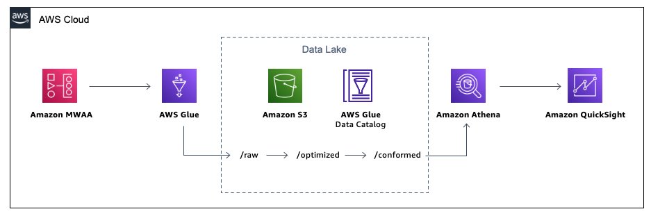
The below diagram illustrates the solution architecture. Please note, Amazon QuickSight is NOT included as part of the CloudFormation stack and is not covered in this tutorial. It has been placed in the diagram to illustrate that metadata can be visualised using a business intelligence tool.

As part of this tutorial, you will be performing the below high-level tasks:

  • Run CloudFormation stack to create all necessary resources
  • Trigger Airflow DAGs to perform sample ETL workload and generate operational metadata in back-end database
  • Trigger Airflow DAG to export operational metadata into Amazon S3
  • Perform analysis with Amazon Athena

This post comes with an AWS CloudFormation stack that automatically provisions the necessary AWS resources and infrastructure, including an active Amazon MWAA instance, for this solution. The entire code is available in the GitHub repository.

The Amazon MWAA instance will already have three directed-acyclic graphs (DAGs) imported:

  1. glue-etl – This ETL workflow leverages AWS Glue to perform transformation logic on a CSV file (customer_activity.csv). This file will be loaded as part of the CloudFormation template into the s3://<DataBucket>/raw/ prefix.

The first task glue_csv_to_parquet converts the ‘raw’ data to parquet format and stores the data in location s3://<DataBucket>/optimised/.  By converting the data in parquet format, you can achieve faster query performance and lower query costs.

The second task glue_transform runs an aggregation over the newly created parquet format and stores the aggregated data in location s3://<DataBucket>/conformed/.

  1. db_export_dag – This DAG consists of one task, export_db, which exports the data from the back-end Airflow database into Amazon S3 in the location s3://<DataBucket>/export/.

Please note that you may experience time-out issues when extracting large amounts of data. On busy Airflow instances, our recommendation will be to set up frequent extracts in small chunks.

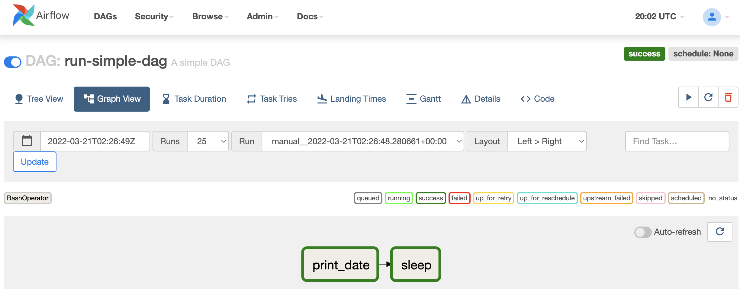
  1. run-simple-dag – This DAG does not perform any data transformation or manipulation. It is used in this blog for the purposes of populating the back-end Airflow database with sufficient operational data.

Prerequisites

To implement the solution outlined in this blog, you will need following :

Steps to run a data pipeline using Amazon MWAA and saving metadata to s3:

  1. Choose Launch Stack:
  2. Choose Next.
  3. For Stack name, enter a name for your stack.
  4. Choose Next.
  5. Keep the default settings on the ‘Configure stack options’ page, and choose Next.
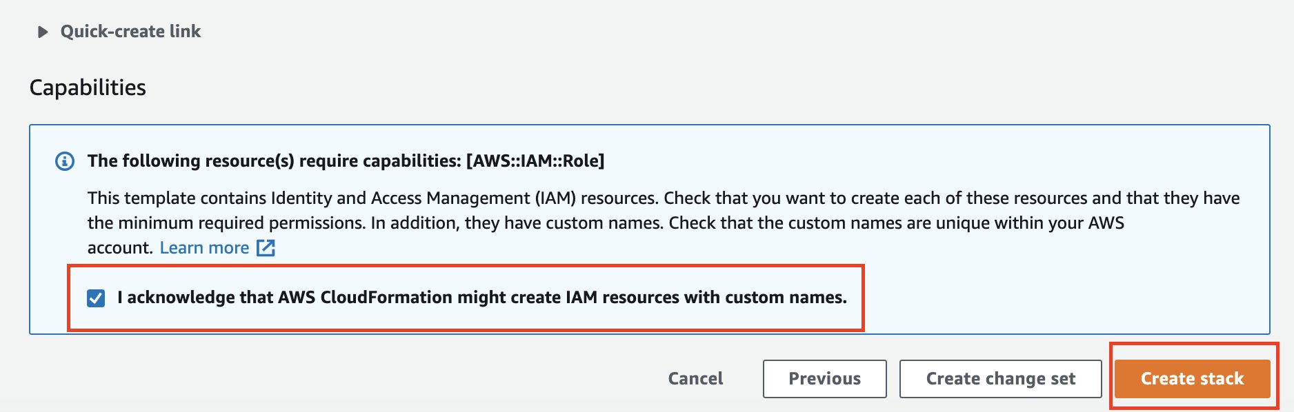
  6. Acknowledge that the template may create AWS Identity and Access Management (IAM) resources.
  7. Choose Create stack. The stack can take up to 30 mins to complete.

The CloudFormation template generates the following resources:

    • VPC infrastructure that uses Public routing over the Internet.
    • Amazon S3 buckets required to support Amazon MWAA, detailed below:
      • The Data Bucket, refered in this blog as s3://<DataBucket>, holds the data which will be optimised and transformed for further analytical consumption. This bucket will also hold the data from the Airflow back-end metadata database once extracted.
      • The Environment Bucket, refered in this blog as s3://<EnvironmentBucket>, stores your DAGs, as well as any custom plugins, and Python dependencies you may have.
    • Amazon MWAA environment that’s associated to the  s3://<EnvironmentBucket>/dags location.
    • AWS Glue jobs for data processing and help generate airflow metadata.
    • AWS Lambda-backed custom resources to upload to Amazon S3 the sample data, AWS Glue scripts and DAG configuration files,
    • AWS Identity and Access Management (IAM) users, roles, and policies.
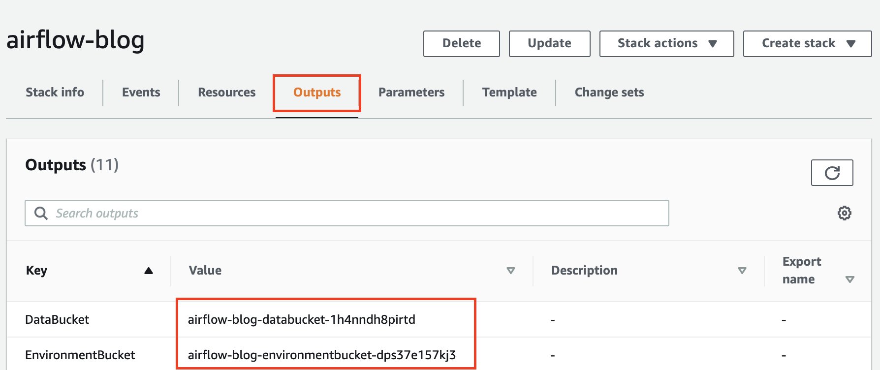
  1. Once the stack creation is successful, navigate to the Outputs tab of the CloudFormation stack and make note of DataBucket and EnvironmentBucket name. Store your Apache Airflow Directed Acyclic Graphs (DAGs), custom plugins in a plugins.zip file, and Python dependencies in a requirements.txt file.
  2. Open the Environments page on the Amazon MWAA console.
  3. Choose the environment created above. (The environment name will include the stack name). Click on Open Airflow UI.
  4. Choose glue-etl DAG , unpause by clicking the radio button next to the name of the DAG and click on the Play Button on Right hand side to Trigger DAG. It may take up to a minute for DAG to appear.
  5. Leave Configuration JSON as empty and hit Trigger.
  6. Choose run-simple-dag DAG, unpause and click on Trigger DAG.
  7. Once both DAG executions have completed, select the db_export_dag DAG, unpause and click on Trigger DAG. Leave Configuration JSON as empty and hit Trigger.

This step will extract the dag and task metadata to a S3 location. This is a sample list of tables and more tables can be added as required. The exported metadata will be located in s3://<DataBucket>/export/ folder.

Visualise using Amazon QuickSight and Amazon Athena

Amazon Athena is a serverless interactive query service that can be used to run exploratory analysis on data stored in Amazon S3.

If you are using Amazon Athena for the first time, please find the steps here to setup query location. We can use Amazon Athena to explore and analyse the metadata generated from airflow dag runs.

  1. Navigate to Athena Console and click explore the query editor.
  2. Hit View Settings.
  3. Click Manage.
  4. Replace with s3://<DataBucket>/logs/athena/. Once completed, return to the query editor.
  5. Before we can perform our pipeline analysis, we need to create the below DDLs. Replace the <DataBucket> as part of the LOCATION clause with the parameter value as defined in the CloudFormation stack (noted in Step 8 above).
    CREATE EXTERNAL TABLE default.airflow_metadata_dagrun (
            sa_instance_state STRING,
            dag_id STRING,
            state STRING,
            start_date STRING,
            run_id STRING,
            external_trigger STRING,
            conf_name STRING,
            dag_hash STRING,
             id STRING,
            execution_date STRING,
            end_date STRING,
            creating_job_id STRING,
            run_type STRING,
            last_scheduling_decision STRING
       )
    PARTITIONED BY (dt string)
    ROW FORMAT DELIMITED
    FIELDS TERMINATED BY ','
    LOCATION 's3://<DataBucket>/export/dagrun/'
    TBLPROPERTIES ("skip.header.line.count"="1");
    MSCK REPAIR TABLE default.airflow_metadata_dagrun;
    
    CREATE EXTERNAL TABLE default.airflow_metadata_taskinstance (
            sa_instance_state STRING,
            start_date STRING,
            job_id STRING,
            pid STRING,
            end_date STRING,
            pool STRING,
            executor_config STRING,
            duration STRING,
            pool_slots STRING,
            external_executor_id STRING,
            state STRING,
            queue STRING,
            try_number STRING,
            max_tries STRING,
            priority_weight STRING,
            task_id STRING,
            hostname STRING,
            operator STRING,
            dag_id STRING,
            unixname STRING,
            queued_dttm STRING,
            execution_date STRING,
            queued_by_job_id STRING,
            test_mode STRING
       )
    PARTITIONED BY (dt string)
    ROW FORMAT DELIMITED
    FIELDS TERMINATED BY ','
    LOCATION 's3://<DataBucket>/export/taskinstance/'
    TBLPROPERTIES ("skip.header.line.count"="1");
    MSCK REPAIR TABLE default.airflow_metadata_taskinstance;

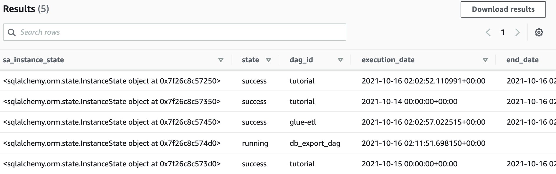
  6. You can preview the table in the query editor of Amazon Athena.

  7. With the metadata persisted, you can perform pipeline monitoring and derive some powerful insights on the performance of your data pipelines overtime. As an example to illustrate this, execute the below SQL query in Athena.

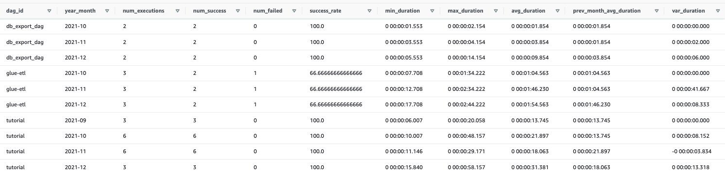
This query returns pertinent metrics at a monthly grain which include number of executions of the DAG in that month, success rate, minimum/maximum/average duration for the month and a variation compared to the previous months average.

Through the below SQL query, you will be able to understand how your data pipelines are performing over time.

select dag_run_prev_month_calcs.*
        , avg_duration - prev_month_avg_duration as var_duration
from
    (
select dag_run_monthly_calcs.*
            , lag(avg_duration, 1, avg_duration) over (partition by dag_id order by year_month) as prev_month_avg_duration
    from
        (
            select dag_id
                    , year_month
                    , sum(counter) as num_executions
                    , sum(success_ind) as num_success
                    , sum(failed_ind) as num_failed
                    , (cast(sum(success_ind) as double)/ sum(counter))*100 as success_rate
                    , min(duration) as min_duration
                    , max(duration) as max_duration
                    , avg(duration) as avg_duration
            from
                (
                    select dag_id
                            , 1 as counter
                            , case when state = 'success' then 1 else 0 end as success_ind
                            , case when state = 'failed' then 1 else 0 end as failed_ind
                            , date_parse(start_date,'%Y-%m-%d %H:%i:%s.%f+00:00') as start_date
                            , date_parse(end_date,'%Y-%m-%d %H:%i:%s.%f+00:00') as end_date
                            , date_parse(end_date,'%Y-%m-%d %H:%i:%s.%f+00:00') - date_parse(start_date,'%Y-%m-%d %H:%i:%s.%f+00:00') as duration
                            , date_format(date_parse(start_date,'%Y-%m-%d %H:%i:%s.%f+00:00'), '%Y-%m') as year_month
                    from "default"."airflow_metadata_dagrun"
                    where state <> 'running'
                )  dag_run_counters
            group by dag_id, year_month
        ) dag_run_monthly_calcs
    ) dag_run_prev_month_calcs
order by dag_id, year_month

  1. You can also visualize this data using your BI tool of choice. While step by step details of creating a dashboard is not covered in this blog, please refer the below dashboard built on Amazon QuickSight as an example of what can be built based on the metadata extracted above. If you are using Amazon QuickSight for the first time, please find the steps here on how to get started.

Through QuickSight, we can quickly visualise and derive that our data pipelines are completing successfully, but on average are taking a longer time to complete over time.

Clean up the environment

  1. Navigate to the S3 console and click on the <DataBucket> noted in step 8 above.
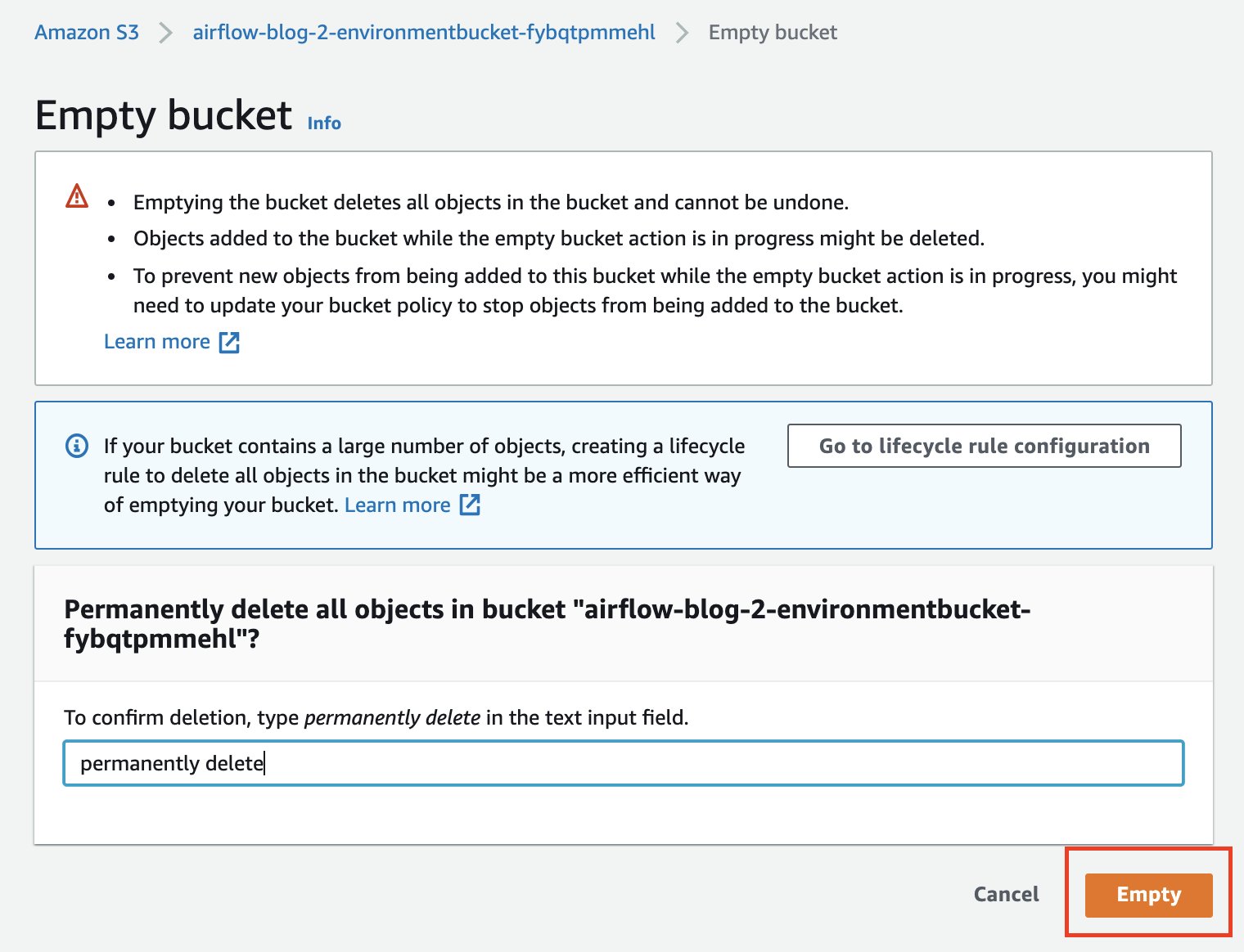
  2. Click on Empty bucket.
  3. Confirm the selection.
  4. Repeat this step for bucket <EnvironmentBucket> (noted in step 8 above) and Empty bucket.
  5. Run the below statements in the query editor to drop the two Amazon Athena tables. Run statements individually.
    DROP TABLE default.airflow_metadata_dagrun;
    DROP TABLE default.airflow_metadata_taskinstance;

  6. On the AWS CloudFormation console, select the stack you created and choose Delete.

Summary

In this post, we presented a solution to further optimise the costs of Amazon MWAA by tearing down instances whilst preserving the metadata. Storing this metadata in your data lake enables you to better perform pipeline monitoring and analysis. This process can be scheduled and orchestrated programatically and is applicable to all Airflow deployments, such as Amazon MWAA, Apache Airflow installed on Amazon EC2, and even on-premises installations of Apache Airflow.

To learn more, please visit Amazon MWAA and Getting Started with Amazon MWAA.


About the Authors

Praveen Kumar is a Specialist Solution Architect at AWS with expertise in designing, building, and implementing modern data and analytics platforms using cloud-native services. His areas of interests are serverless technology, streaming applications, and modern cloud data warehouses.

Avnish Jain is a Specialist Solution Architect in Analytics at AWS with experience designing and implementing scalable, modern data platforms on the cloud for large scale enterprises. He is passionate about helping customers build performant and robust data-driven solutions and realise their data & analytics potential.

Create a serverless event-driven workflow to ingest and process Microsoft data with AWS Glue and Amazon EventBridge

Post Syndicated from Venkata Sistla original https://aws.amazon.com/blogs/big-data/create-a-serverless-event-driven-workflow-to-ingest-and-process-microsoft-data-with-aws-glue-and-amazon-eventbridge/

Microsoft SharePoint is a document management system for storing files, organizing documents, and sharing and editing documents in collaboration with others. Your organization may want to ingest SharePoint data into your data lake, combine the SharePoint data with other data that’s available in the data lake, and use it for reporting and analytics purposes. AWS Glue is a serverless data integration service that makes it easy to discover, prepare, and combine data for analytics, machine learning, and application development. AWS Glue provides all the capabilities needed for data integration so that you can start analyzing your data and putting it to use in minutes instead of months.

Organizations often manage their data on SharePoint in the form of files and lists, and you can use this data for easier discovery, better auditing, and compliance. SharePoint as a data source is not a typical relational database and the data is mostly semi structured, which is why it’s often difficult to join the SharePoint data with other relational data sources. This post shows how to ingest and process SharePoint lists and files with AWS Glue and Amazon EventBridge, which enables you to join other data that is available in your data lake. We use SharePoint REST APIs with a standard open data protocol (OData) syntax. OData advocates a standard way of implementing REST APIs that allows for SQL-like querying capabilities. OData helps you focus on your business logic while building RESTful APIs without having to worry about the various approaches to define request and response headers, query options, and so on.

AWS Glue event-driven workflows

Unlike a traditional relational database, SharePoint data may or may not change frequently, and it’s difficult to predict the frequency at which your SharePoint server generates new data, which makes it difficult to plan and schedule data processing pipelines efficiently. Running data processing frequently can be expensive, whereas scheduling pipelines to run infrequently can deliver cold data. Similarly, triggering pipelines from an external process can increase complexity, cost, and job startup time.

AWS Glue supports event-driven workflows, a capability that lets developers start AWS Glue workflows based on events delivered by EventBridge. The main reason to choose EventBridge in this architecture is because it allows you to process events, update the target tables, and make information available to consume in near-real time. Because frequency of data change in SharePoint is unpredictable, using EventBridge to capture events as they arrive enables you to run the data processing pipeline only when new data is available.

To get started, you simply create a new AWS Glue trigger of type EVENT and place it as the first trigger in your workflow. You can optionally specify a batching condition. Without event batching, the AWS Glue workflow is triggered every time an EventBridge rule matches, which may result in multiple concurrent workflows running. AWS Glue protects you by setting default limits that restrict the number of concurrent runs of a workflow. You can increase the required limits by opening a support case. Event batching allows you to configure the number of events to buffer or the maximum elapsed time before firing the particular trigger. When the batching condition is met, a workflow run is started. For example, you can trigger your workflow when 100 files are uploaded in Amazon Simple Storage Service (Amazon S3) or 5 minutes after the first upload. We recommend configuring event batching to avoid too many concurrent workflows, and optimize resource usage and cost.

To illustrate this solution better, consider the following use case for a wine manufacturing and distribution company that operates across multiple countries. They currently host all their transactional system’s data on a data lake in Amazon S3. They also use SharePoint lists to capture feedback and comments on wine quality and composition from their suppliers and other stakeholders. The supply chain team wants to join their transactional data with the wine quality comments in SharePoint data to improve their wine quality and manage their production issues better. They want to capture those comments from the SharePoint server within an hour and publish that data to a wine quality dashboard in Amazon QuickSight. With an event-driven approach to ingest and process their SharePoint data, the supply chain team can consume the data in less than an hour.

Overview of solution

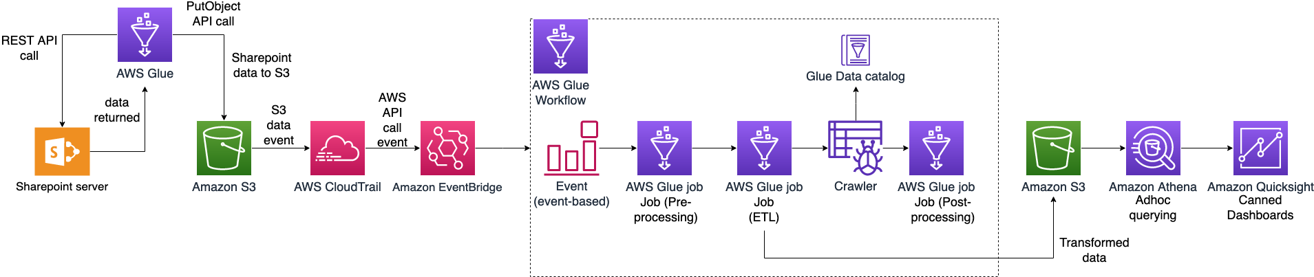
In this post, we walk through a solution to set up an AWS Glue job to ingest SharePoint lists and files into an S3 bucket and an AWS Glue workflow that listens to S3 PutObject data events captured by AWS CloudTrail. This workflow is configured with an event-based trigger to run when an AWS Glue ingest job adds new files into the S3 bucket. The following diagram illustrates the architecture.

To make it simple to deploy, we captured the entire solution in an AWS CloudFormation template that enables you to automatically ingest SharePoint data into Amazon S3. SharePoint uses ClientID and TenantID credentials for authentication and uses Oauth2 for authorization.

The template helps you perform the following steps:

  1. Create an AWS Glue Python shell job to make the REST API call to the SharePoint server and ingest files or lists into Amazon S3.
  2. Create an AWS Glue workflow with a starting trigger of EVENT type.
  3. Configure CloudTrail to log data events, such as PutObject API calls to CloudTrail.
  4. Create a rule in EventBridge to forward the PutObject API events to AWS Glue when they’re emitted by CloudTrail.
  5. Add an AWS Glue event-driven workflow as a target to the EventBridge rule. The workflow gets triggered when the SharePoint ingest AWS Glue job adds new files to the S3 bucket.

Prerequisites

For this walkthrough, you should have the following prerequisites:

Configure SharePoint server authentication details

Before launching the CloudFormation stack, you need to set up your SharePoint server authentication details, namely, TenantID, Tenant, ClientID, ClientSecret, and the SharePoint URL in AWS Systems Manager Parameter Store of the account you’re deploying in. This makes sure that no authentication details are stored in the code and they’re fetched in real time from Parameter Store when the solution is running.

To create your AWS Systems Manager parameters, complete the following steps:

  1. On the Systems Manager console, under Application Management in the navigation pane, choose Parameter Store.
    systems manager
  2. Choose Create Parameter.
  3. For Name, enter the parameter name /DATALAKE/GlueIngest/SharePoint/tenant.
  4. Leave the type as string.
  5. Enter your SharePoint tenant detail into the value field.
  6. Choose Create parameter.
  7. Repeat these steps to create the following parameters:
    1. /DataLake/GlueIngest/SharePoint/tenant
    2. /DataLake/GlueIngest/SharePoint/tenant_id
    3. /DataLake/GlueIngest/SharePoint/client_id/list
    4. /DataLake/GlueIngest/SharePoint/client_secret/list
    5. /DataLake/GlueIngest/SharePoint/client_id/file
    6. /DataLake/GlueIngest/SharePoint/client_secret/file
    7. /DataLake/GlueIngest/SharePoint/url/list
    8. /DataLake/GlueIngest/SharePoint/url/file

Deploy the solution with AWS CloudFormation

For a quick start of this solution, you can deploy the provided CloudFormation stack. This creates all the required resources in your account.

The CloudFormation template generates the following resources:

  • S3 bucket – Stores data, CloudTrail logs, job scripts, and any temporary files generated during the AWS Glue extract, transform, and load (ETL) job run.
  • CloudTrail trail with S3 data events enabled – Enables EventBridge to receive PutObject API call data in a specific bucket.
  • AWS Glue Job – A Python shell job that fetches the data from the SharePoint server.
  • AWS Glue workflow – A data processing pipeline that is comprised of a crawler, jobs, and triggers. This workflow converts uploaded data files into Apache Parquet format.
  • AWS Glue database – The AWS Glue Data Catalog database that holds the tables created in this walkthrough.
  • AWS Glue table – The Data Catalog table representing the Parquet files being converted by the workflow.
  • AWS Lambda function – The AWS Lambda function is used as an AWS CloudFormation custom resource to copy job scripts from an AWS Glue-managed GitHub repository and an AWS Big Data blog S3 bucket to your S3 bucket.
  • IAM roles and policies – We use the following AWS Identity and Access Management (IAM) roles:
    • LambdaExecutionRole – Runs the Lambda function that has permission to upload the job scripts to the S3 bucket.
    • GlueServiceRole – Runs the AWS Glue job that has permission to download the script, read data from the source, and write data to the destination after conversion.
    • EventBridgeGlueExecutionRole – Has permissions to invoke the NotifyEvent API for an AWS Glue workflow.
    • IngestGlueRole – Runs the AWS Glue job that has permission to ingest data into the S3 bucket.

To launch the CloudFormation stack, complete the following steps:

  1. Sign in to the AWS CloudFormation console.
  2. Choose Launch Stack:
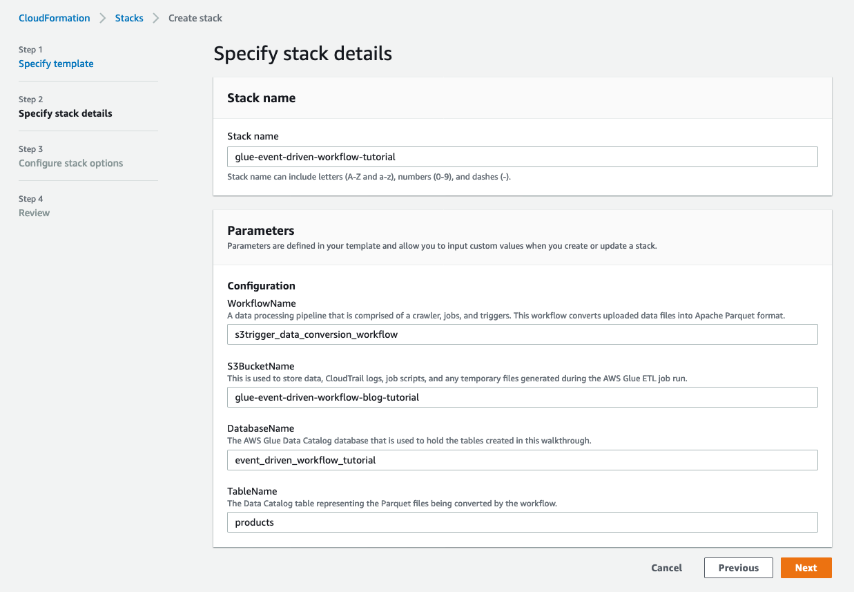
  3. Choose Next.
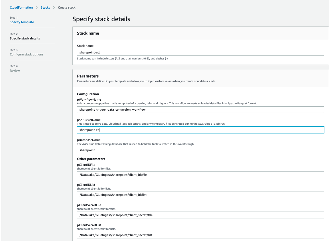
  4. For pS3BucketName, enter the unique name of your new S3 bucket.
  5. Leave pWorkflowName and pDatabaseName as the default.

cloud formation 1

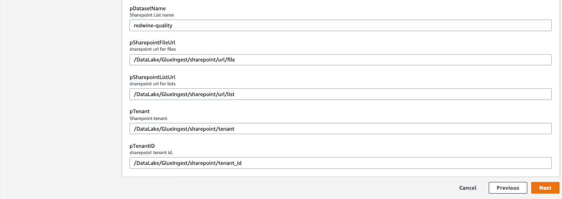
  1. For pDatasetName, enter the SharePoint list name or file name you want to ingest.
  2. Choose Next.

cloud formation 2

  1. On the next page, choose Next.
  2. Review the details on the final page and select I acknowledge that AWS CloudFormation might create IAM resources.
  3. Choose Create.

It takes a few minutes for the stack creation to complete; you can follow the progress on the Events tab.

You can run the ingest AWS Glue job either on a schedule or on demand. As the job successfully finishes and ingests data into the raw prefix of the S3 bucket, the AWS Glue workflow runs and transforms the ingested raw CSV files into Parquet files and loads them into the transformed prefix.

Review the EventBridge rule

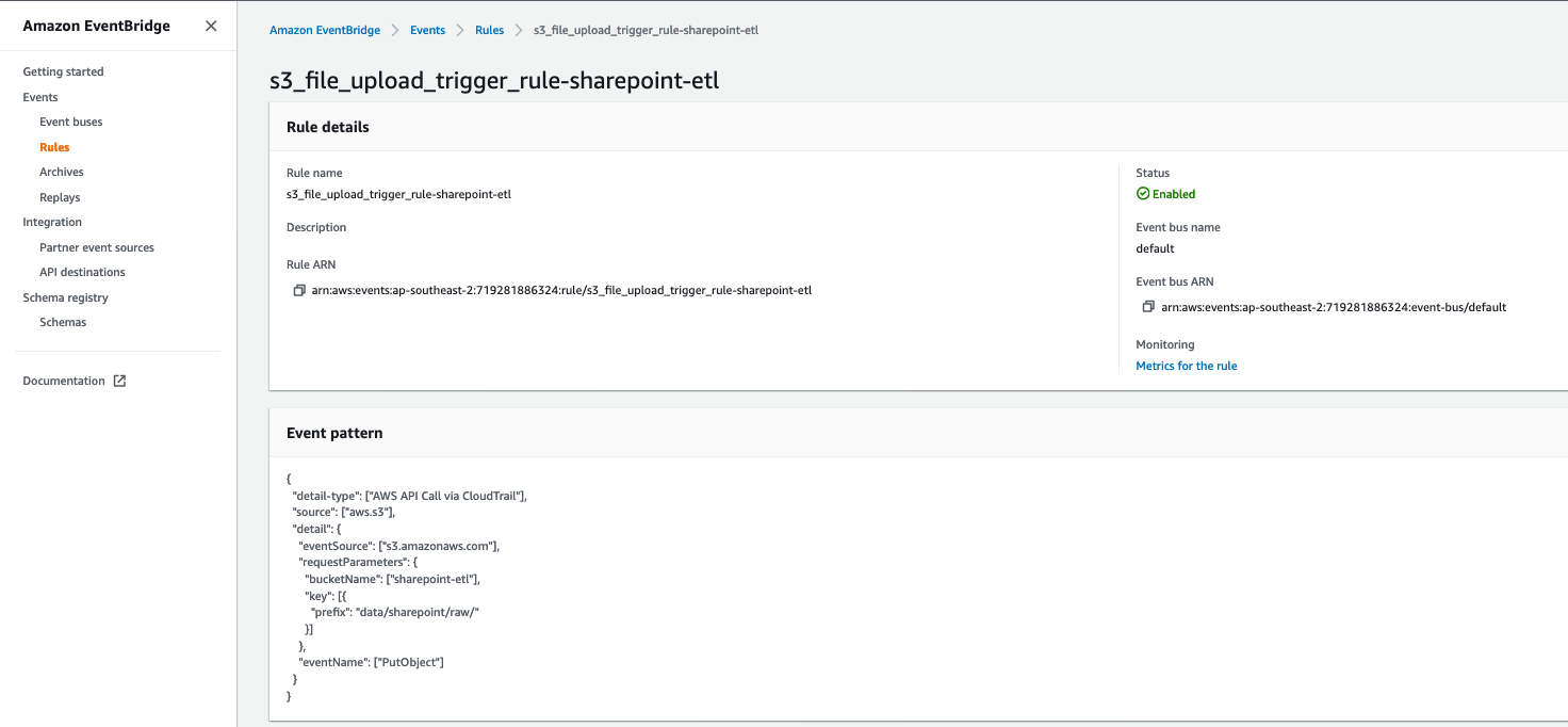
The CloudFormation template created an EventBridge rule to forward S3 PutObject API events to AWS Glue. Let’s review the configuration of the EventBridge rule:

  1. On the EventBridge console, under Events, choose Rules.
  2. Choose the rule s3_file_upload_trigger_rule-<CloudFormation-stack-name>.
  3. Review the information in the Event pattern section.

event bridge

The event pattern shows that this rule is triggered when an S3 object is uploaded to s3://<bucket_name>/data/SharePoint/tablename_raw/. CloudTrail captures the PutObject API calls made and relays them as events to EventBridge.

  1. In the Targets section, you can verify that this EventBridge rule is configured with an AWS Glue workflow as a target.

event bridge target section

Run the ingest AWS Glue job and verify the AWS Glue workflow is triggered successfully

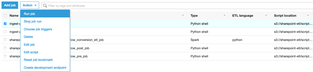
To test the workflow, we run the ingest-glue-job-SharePoint-file job using the following steps:

  1. On the AWS Glue console, select the ingest-glue-job-SharePoint-file job.

glue job

  1. On the Action menu, choose Run job.

glue job action menu

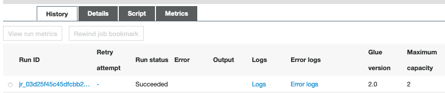
  1. Choose the History tab and wait until the job succeeds.

glue job history tab

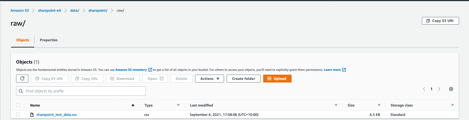
You can now see the CSV files in the raw prefix of your S3 bucket.

csv file s3 location

Now the workflow should be triggered.

  1. On the AWS Glue console, validate that your workflow is in the RUNNING state.

glue workflow running status

  1. Choose the workflow to view the run details.
  2. On the History tab of the workflow, choose the current or most recent workflow run.
  3. Choose View run details.

glue workflow visual

When the workflow run status changes to Completed, let’s check the converted files in your S3 bucket.

  1. Switch to the Amazon S3 console, and navigate to your bucket.

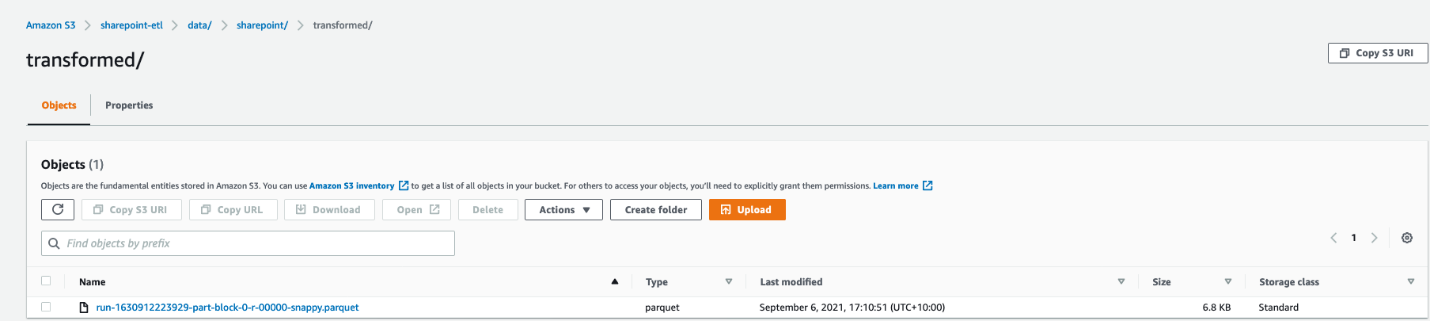
You can see the Parquet files under s3://<bucket_name>/data/SharePoint/tablename_transformed/.

parquet file s3 location

Congratulations! Your workflow ran successfully based on S3 events triggered by uploading files to your bucket. You can verify everything works as expected by running a query against the generated table using Amazon Athena.

Sample wine dataset

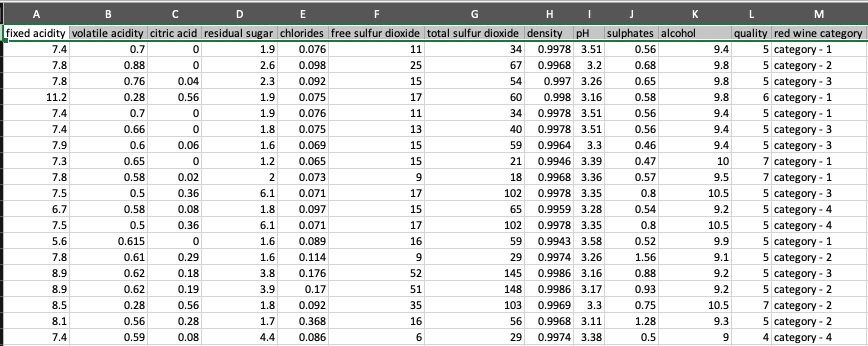
Let’s analyze a sample red wine dataset. The following screenshot shows a SharePoint list that contains various readings that relate to the characteristics of the wine and an associated wine category. This is populated by various wine tasters from multiple countries.

redwine dataset

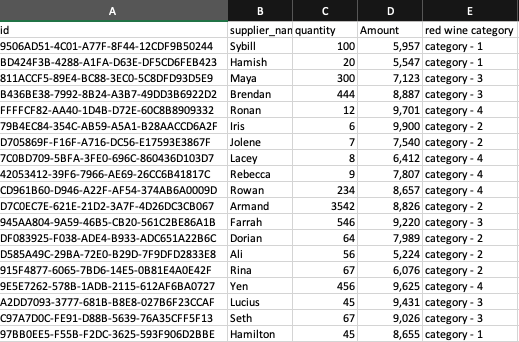
The following screenshot shows a supplier dataset from the data lake with wine categories ordered per supplier.

supplier dataset

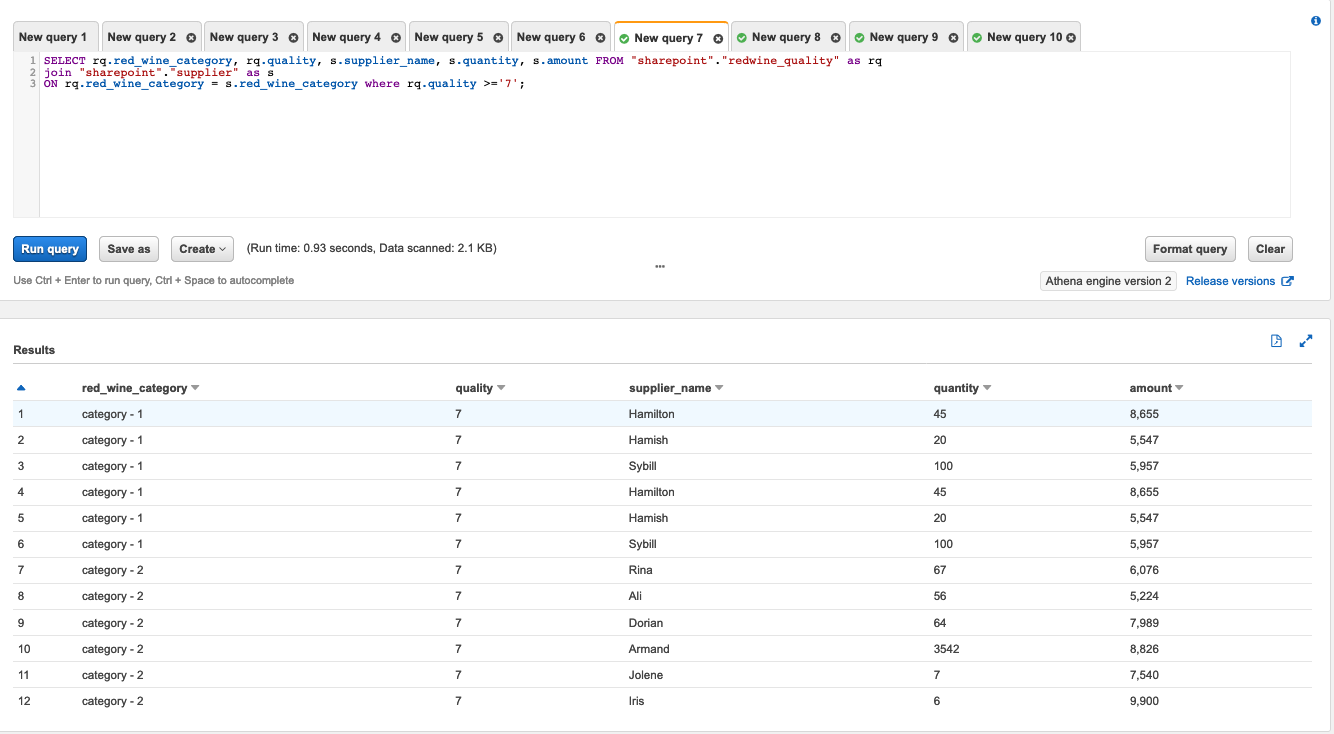
We process the red wine dataset using this solution and use Athena to query the red wine data and supplier data where wine quality is greater than or equal to 7.

athena query and results

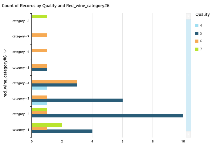
We can visualize the processed dataset using QuickSight.

Clean up

To avoid incurring unnecessary charges, you can use the AWS CloudFormation console to delete the stack that you deployed. This removes all the resources you created when deploying the solution.

Conclusion

Event-driven architectures provide access to near-real-time information and help you make business decisions on fresh data. In this post, we demonstrated how to ingest and process SharePoint data using AWS serverless services like AWS Glue and EventBridge. We saw how to configure a rule in EventBridge to forward events to AWS Glue. You can use this pattern for your analytical use cases, such as joining SharePoint data with other data in your lake to generate insights, or auditing SharePoint data and compliance requirements.


About the Author

Venkata Sistla is a Big Data & Analytics Consultant on the AWS Professional Services team. He specializes in building data processing capabilities and helping customers remove constraints that prevent them from leveraging their data to develop business insights.

Build a serverless event-driven workflow with AWS Glue and Amazon EventBridge

Post Syndicated from Noritaka Sekiyama original https://aws.amazon.com/blogs/big-data/build-a-serverless-event-driven-workflow-with-aws-glue-and-amazon-eventbridge/

Customers are adopting event-driven-architectures to improve the agility and resiliency of their applications. As a result, data engineers are increasingly looking for simple-to-use yet powerful and feature-rich data processing tools to build pipelines that enrich data, move data in and out of their data lake and data warehouse, and analyze data. AWS Glue is a serverless data integration service that makes it easy to discover, prepare, and combine data for analytics, machine learning, and application development. AWS Glue provides all the capabilities needed for data integration so that you can start analyzing your data and putting it to use in minutes instead of months.

Data integration jobs have varying degrees of priority and time sensitivity. For example, you can use batch processing to process weekly sales data but in some cases, data needs to be processed immediately. Fraud detection applications, for example, require near-real-time processing of security logs. Or if a partner uploads product information to your Amazon Simple Storage Service (Amazon S3) bucket, it needs to be processed right away to ensure that your website has the latest product information.

This post discusses how to configure AWS Glue workflows to run based on real-time events. You no longer need to set schedules or build complex solutions to trigger jobs based on events; AWS Glue event-driven workflows manage it all for you.

Get started with AWS Glue event-driven workflows

As a business requirement, most companies need to hydrate their data lake and data warehouse with data in near-real time. They run their pipelines on a schedule (hourly, daily, or even weekly) or trigger the pipeline through an external system. It’s difficult to predict the frequency at which upstream systems generate data, which makes it difficult to plan and schedule ETL pipelines to run efficiently. Scheduling ETL pipelines to run too frequently can be expensive, whereas scheduling pipelines to run infrequently can lead to making decisions based on stale data. Similarly, triggering pipelines from an external process can increase complexity, cost, and job startup time.

AWS Glue now supports event-driven workflows, a capability that lets developers start AWS Glue workflows based on events delivered by Amazon EventBridge. With this new feature, you can trigger a data integration workflow from any events from AWS services, software as a service (SaaS) providers, and any custom applications. For example, you can react to an S3 event generated when new buckets are created and when new files are uploaded to a specific S3 location. In addition, if your environment generates many events, AWS Glue allows you to batch them either by time duration or by the number of events. Event-driven workflows make it easy to start an AWS Glue workflow based on real-time events.

To get started, you simply create a new AWS Glue trigger of type EVENT and place it as the first trigger in your workflow. You can optionally specify a batching condition. Without event batching, the AWS Glue workflow is triggered every time an EventBridge rule matches which may result in multiple concurrent workflow runs. In some environments, starting many concurrent workflow runs could lead to throttling, reaching service quota limits, and potential cost overruns. This can also result in workflow execution failures in case the concurrency limit specified on the workflow and the jobs within the workflow do not match. Event batching allows you to configure the number of events to buffer or the maximum elapsed time before firing the particular trigger. Once the batching condition is met, a workflow run is started. For example, you can trigger your workflow when 100 files are uploaded in S3 or 5 minutes after the first upload. We recommend configuring event batching to avoid too many concurrent workflow runs, and optimize resource usage and cost.

Overview of the solution

In this post, we walk through a solution to set up an AWS Glue workflow that listens to S3 PutObject data events captured by AWS CloudTrail. This workflow is configured to run when five new files are added or the batching window time of 900 seconds expires after first file is added. The following diagram illustrates the architecture.

The steps in this solution are as follows:

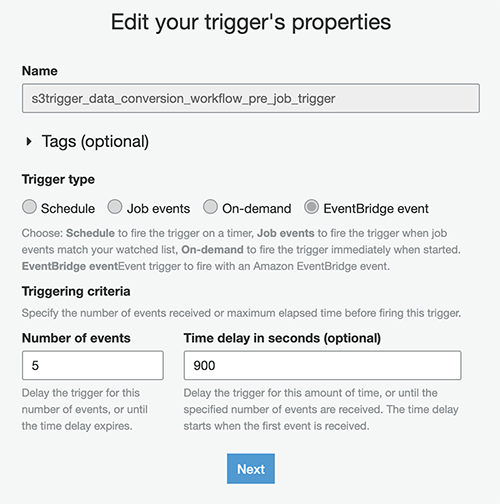
  1. Create an AWS Glue workflow with a starting trigger of EVENT type and configure the batch size on the trigger to be five and batch window to be 900 seconds.
  2. Configure Amazon S3 to log data events, such as PutObject API calls to CloudTrail.
  3. Create a rule in EventBridge to forward the PutObject API events to AWS Glue when they are emitted by CloudTrail.
  4. Add an AWS Glue event-driven workflow as a target to the EventBridge rule.
  5. To start the workflow, upload files to the S3 bucket. Remember you need to have at least five files before the workflow is triggered.

Deploy the solution with AWS CloudFormation

For a quick start of this solution, you can deploy the provided AWS CloudFormation stack. This creates all the required resources in your account.

The CloudFormation template generates the following resources:

  • S3 bucket – This is used to store data, CloudTrail logs, job scripts, and any temporary files generated during the AWS Glue ETL job run.
  • CloudTrail trail with S3 data events enabled – This enables EventBridge to receive PutObject API call data on specific bucket.
  • AWS Glue workflow – A data processing pipeline that is comprised of a crawler, jobs, and triggers. This workflow converts uploaded data files into Apache Parquet format.
  • AWS Glue database – The AWS Glue Data Catalog database that is used to hold the tables created in this walkthrough.
  • AWS Glue table – The Data Catalog table representing the Parquet files being converted by the workflow.
  • AWS Lambda function – This is used as an AWS CloudFormation custom resource to copy job scripts from an AWS Glue-managed GitHub repository and an AWS Big Data blog S3 bucket to your S3 bucket.
  • IAM roles and policies – We use the following AWS Identity and Access Management (IAM) roles:
    • LambdaExecutionRole – Runs the Lambda function that has permission to upload the job scripts to the S3 bucket.
    • GlueServiceRole – Runs the AWS Glue job that has permission to download the script, read data from the source, and write data to the destination after conversion.
    • EventBridgeGlueExecutionRole – Has permissions to invoke the NotifyEvent API for an AWS Glue workflow.

To launch the CloudFormation stack, complete the following steps:

  1. Sign in to the AWS CloudFormation console.
  2. Choose Launch Stack:

  1. Choose Next.
  2. For S3BucketName, enter the unique name of your new S3 bucket.
  3. For WorkflowName, DatabaseName, and TableName, leave as the default.
  4. Choose Next.

  1. On the next page, choose Next.
  2. Review the details on the final page and select I acknowledge that AWS CloudFormation might create IAM resources.
  3. Choose Create.

It takes a few minutes for the stack creation to complete; you can follow the progress on the Events tab.

By default, the workflow runs whenever a single file is uploaded to the S3 bucket, resulting in a PutObject API call. In the next section, we configure the event batching to change this behavior.

Review the AWS Glue trigger and add event batching conditions

The CloudFormation template provisioned an AWS Glue workflow including a crawler, jobs, and triggers. The first trigger in the workflow is configured as an event-based trigger. Next, we update this trigger to batch five events or wait for 900 seconds after the first event before it starts the workflow.

Before we make any changes, let’s review the trigger on the AWS Glue console:

  1. On the AWS Glue console, under ETL, choose Triggers.
  2. Choose <Workflow-name>_pre_job_trigger.
  3. Choose Edit.

We can see the trigger’s type is set to EventBridge event, which means it’s an event-based trigger. Let’s change the event batching condition to run the workflow after five files are uploaded to Amazon S3.

  1. For Number of events, enter 5.
  2. For Time delay (sec), enter 900.
  3. Choose Next.

  1. On the next screen, under Choose jobs to trigger, leave as the default and choose Next.
  2. Choose Finish.

Review the EventBridge rule

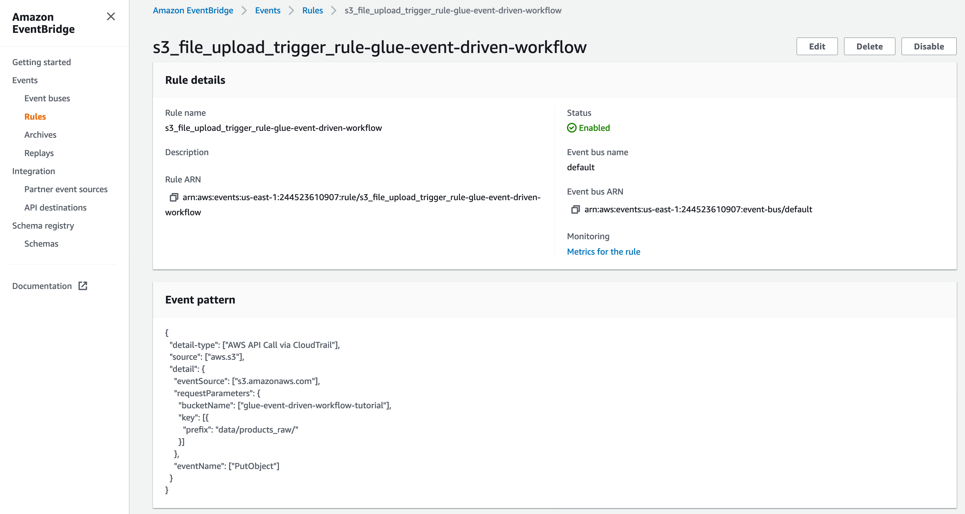
The CloudFormation template created an EventBridge rule to forward S3 PutObject API events to AWS Glue. Let’s review the configuration of the EventBridge rule:

  1. On the EventBridge console, under Events, choose Rules.
  2. Choose s3_file_upload_trigger_rule-<CloudFormation-stack-name>.
  3. Review the information in the Event pattern section.

The event pattern shows that this rule is triggered when an S3 object is uploaded to s3://<bucket_name>/data/products_raw/. CloudTrail captures the PutObject API calls made and relays them as events to EventBridge.

  1. In the Targets section, you can verify that this EventBridge rule is configured with an AWS Glue workflow as a target.

Trigger the AWS Glue workflow by uploading files to Amazon S3

To test your workflow, we upload files to Amazon S3 using the AWS Command Line Interface (AWS CLI). If you don’t have the AWS CLI, see Installing, updating, and uninstalling the AWS CLI.

Let’s upload some small files to your S3 bucket.

  1. Run the following command to upload the first file to your S3 bucket:
$ echo '{"product_id": "00001", "product_name": "Television", "created_at": "2021-06-01"}' > product_00001.json
$ aws s3 cp product_00001.json s3://<bucket-name>/data/products_raw/
  1. Run the following command to upload the second file:
$ echo '{"product_id": "00002", "product_name": "USB charger", "created_at": "2021-06-02"}' > product_00002.json
$ aws s3 cp product_00002.json s3://<bucket-name>/data/products_raw/
  1. Run the following command to upload the third file:
$ echo '{"product_id": "00003", "product_name": "USB charger", "created_at": "2021-06-03"}' &gt; product_00003.json<br />
$ aws s3 cp product_00003.json s3://<bucket-name>/data/products_raw/
  1. Run the following command to upload the fourth file:
$ echo '{"product_id": "00004", "product_name": "USB charger", "created_at": "2021-06-04"}' &gt; product_00004.json<br />
$ aws s3 cp product_00004.json s3://<bucket-name>/data/products_raw/

These events didn’t trigger the workflow because it didn’t meet the batch condition of five events.

  1. Run the following command to upload the fifth file:
$ echo '{"product_id": "00005", "product_name": "USB charger", "created_at": "2021-06-05"}' > product_00005.json
$ aws s3 cp product_00005.json s3://<bucket-name>/data/products_raw/

Now the five JSON files have been uploaded to Amazon S3.

Verify the AWS Glue workflow is triggered successfully

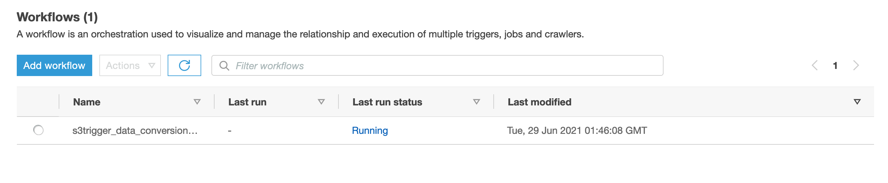
Now the workflow should be triggered. Open the AWS Glue console to validate that your workflow is in the RUNNING state.

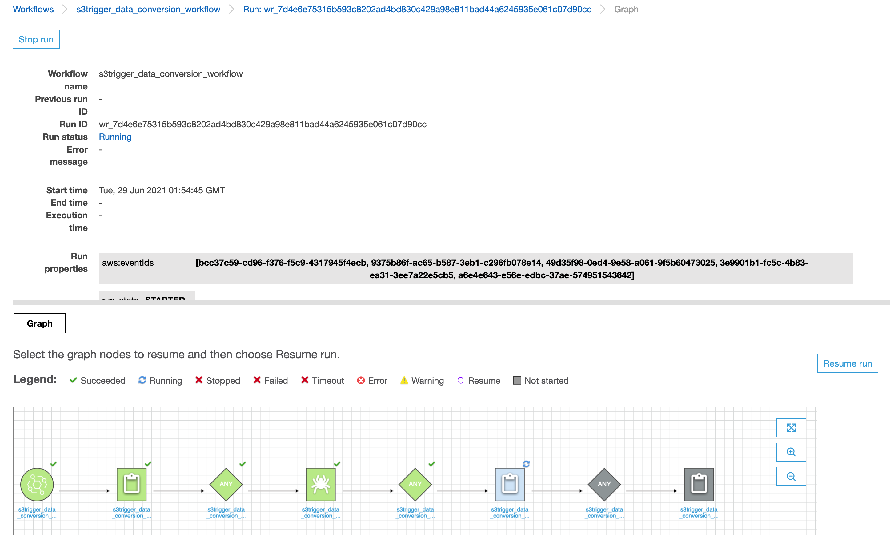
To view the run details, complete the following steps:

  1. On the History tab of the workflow, choose the current or most recent workflow run.
  2. Choose View run details.

When the workflow run status changes to Completed, let’s see the converted files in your S3 bucket.

  1. Switch to the Amazon S3 console, and navigate to your bucket.

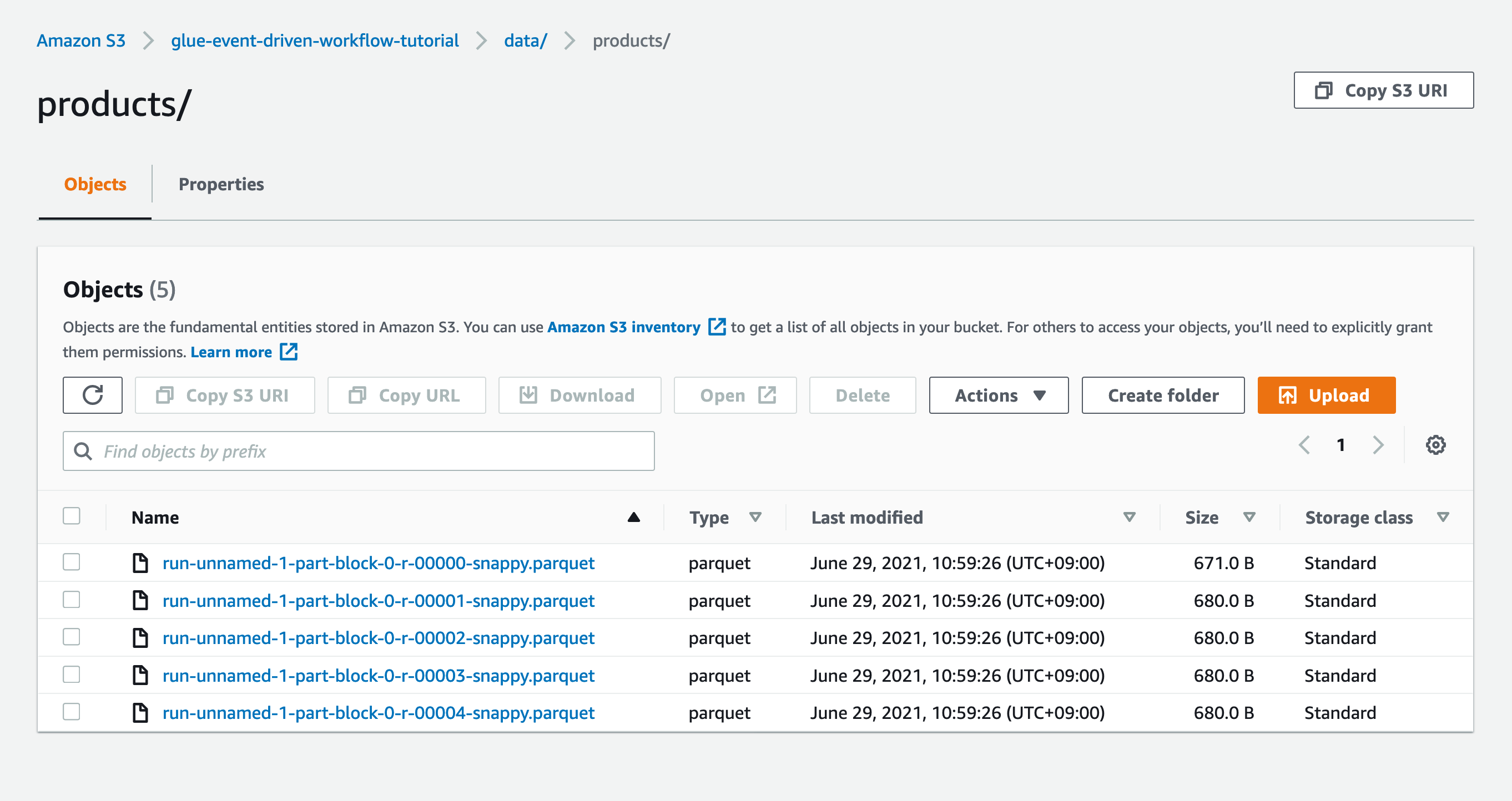
You can see the Parquet files under s3://<bucket-name>/data/products/.

Congratulations! Your workflow ran successfully based on S3 events triggered by uploading files to your bucket. You can verify everything works as expected by running a query against the generated table using Amazon Athena.

Verify the metrics for the EventBridge rule

Optionally, you can use Amazon CloudWatch metrics to validate the events were sent to the AWS Glue workflow.

  1. On the EventBridge console, in the navigation pane, choose Rules.
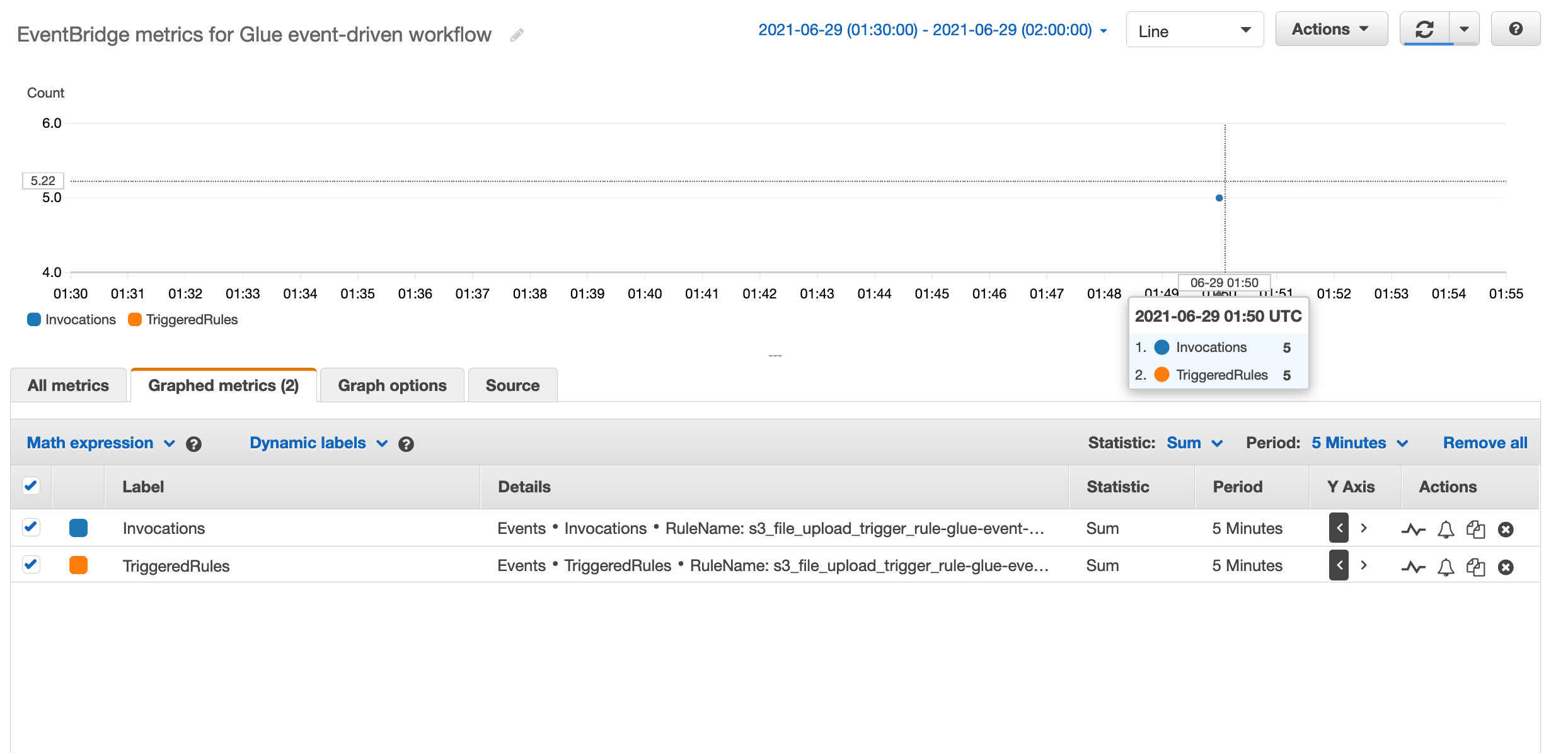
  2. Select your EventBridge rule s3_file_upload_trigger_rule-<Workflow-name> and choose Metrics for the rule.

When the target workflow is invoked by the rule, the metrics Invocations and TriggeredRules are published.

The metric FailedInvocations is published if the EventBridge rule is unable to trigger the AWS Glue workflow. In that case, we recommend you check the following configurations:

  • Verify the IAM role provided to the EventBridge rule allows the glue:NotifyEvent permission on the AWS Glue workflow.
  • Verify the trust relationship on the IAM role provides the events.amazonaws.com service principal the ability to assume the role.
  • Verify the starting trigger on your target AWS Glue workflow is an event-based trigger.

Clean up

Now to the final step, cleaning up the resources. Delete the CloudFormation stack to remove any resources you created as part of this walkthrough.

Conclusion

AWS Glue event-driven workflows enable data engineers to easily build event driven ETL pipelines that respond in near-real time, delivering fresh data to business users. In this post, we demonstrated how to configure a rule in EventBridge to forward events to AWS Glue. We also saw how to create an event-based trigger that either immediately, or after a set number of events or period of time, starts a Glue ETL workflow. Migrating your existing AWS Glue workflows to make them event-driven is easy. This can be simply done by replacing the first trigger in the workflow to be of type EVENT and adding this workflow as a target to an EventBridge rule that captures events of your interest.

For more information about event-driven AWS Glue workflows, see Starting an AWS Glue Workflow with an Amazon EventBridge Event.


About the Authors

Noritaka Sekiyama is a Senior Big Data Architect on the AWS Glue and AWS Lake Formation team. In his spare time, he enjoys playing with his children. They are addicted to grabbing crayfish and worms in the park, and putting them in the same jar to observe what happens.


Karan Vishwanathan is a Software Development Engineer on the AWS Glue team. He enjoys working on distributed systems problems and playing golf.


Keerthi Chadalavada is a Software Development Engineer on the AWS Glue team. She is passionate about building fault tolerant and reliable distributed systems at scale.

Hydrate your data lake with SaaS application data using Amazon AppFlow

Post Syndicated from Ninad Phatak original https://aws.amazon.com/blogs/big-data/hydrate-your-data-lake-with-saas-application-data-using-amazon-appflow/

Organizations today want to make data-driven decisions. The data could lie in multiple source systems, such as line of business applications, log files, connected devices, social media, and many more. As organizations adopt software as a service (SaaS) applications, data becomes increasingly fragmented and trapped in different “data islands.” To make decision-making easier, organizations are building data lakes, which is a centralized repository that allows you to store all your structured and unstructured data at any scale. You can store your data as is, without having to first structure the data, and run different types of analytics—from dashboards and visualizations to big data processing, ad hoc analytics, and machine learning (ML) to guide better decisions.
AWS provides services such as AWS Glue, AWS Lake Formation, Amazon Database Migration Service (AWS DMS), and many third-party solutions on AWS Marketplace to integrate data from various source systems into the Amazon Simple Storage Service (Amazon S3) data lake. If you’re using SaaS applications like Salesforce, Marketo, Slack, and ServiceNow to run your business, you may need to integrate data from these sources into your data lake. You likely also want to easily integrate these data sources without writing or managing any code. This is precisely where you can use Amazon AppFlow.

Amazon AppFlow is a fully managed integration service that enables you to securely transfer data between SaaS applications like Salesforce, Marketo, Slack, and ServiceNow and AWS services like Amazon S3 and Amazon Redshift. With Amazon AppFlow, you can run data flows at nearly any scale at the frequency you choose—on a schedule, in response to a business event in real time, or on demand. You can configure data transformations such as data masking and concatenation of fields as well as validate and filter data (omitting records that don’t fit a criteria) to generate rich, ready-to-use data as part of the flow itself, without additional steps. Amazon AppFlow automatically encrypts data in motion, and optionally allows you to restrict data from flowing over the public internet for SaaS applications that are integrated with AWS PrivateLink, reducing exposure to security threats. For a complete list of all the SaaS applications that can be integrated with Amazon AppFlow, see Amazon AppFlow integrations.

In this post, we look at how to integrate data from Salesforce into a data lake and query the data via Amazon Athena. Amazon AppFlow recently announced multiple new capabilities such as availability of APIs and integration with AWS CloudFormation. We take advantage of these new capabilities and deploy the solution using a CloudFormation template.

Solution architecture

The following diagram depicts the architecture of the solution that we deploy using AWS CloudFormation.

As seen in the diagram, we use Amazon AppFlow to integrate data from Salesforce into a data lake on Amazon S3. We then use Athena to query this data with the table definitions residing in the AWS Glue Data Catalog.

Deploy the solution with AWS CloudFormation

We use AWS CloudFormation to deploy the solution components in your AWS account. Choose an AWS Region for deployment where the following services are available:

  • Amazon AppFlow
  • AWS Glue
  • Amazon S3
  • Athena

You need to meet the following prerequisites before deploying the solution:

  • Have a Salesforce account with credentials authorized to pull data using APIs.
  • If you’re deploying the stack in an account using the Lake Formation permission model, validate the following settings:
    • The AWS Identity and Access Management (IAM) user used to deploy the stack is added as a data lake administrator under Lake Formation, or the IAM user used to deploy the stack has IAM privileges to create databases in the AWS Glue Data Catalog.
    • The Data Catalog settings under Lake Formation are configured to use only IAM access control for new databases and new tables in new databases. This makes sure that all access to the newly created databases and tables in the Data Catalog are controlled solely using IAM permissions. The following screenshot shows the Data catalog settings page on the Lake Formation console, where you can set these permissions.

These Lake Formation settings are required so that all permissions to the Data Catalog objects are controlled using IAM only.

Although you need these Lake Formation settings for the CloudFormation stack to deploy properly, in a production setting we recommend you use Lake Formation to govern access to the data in the data lake. For more information about Lake Formation, see What Is AWS Lake Formation?

We now deploy the solution and the following components:

  • An Amazon AppFlow flow to integrate Salesforce account data into Amazon S3
  • An AWS Glue Data Catalog database
  • An AWS Glue crawler to crawl the data pulled into Amazon S3 so that it can be queried using Athena.
  1. On the Amazon AppFlow console, on the Connections page, choose Create connection.
  2. For Connection name, enter a name for your connection.
  3. Choose Continue.

You’re redirected to the Salesforce login page, where you enter your Salesforce account credentials.

  1. Enter the appropriate credentials and grant OAuth2 access to the Amazon AppFlow client in the next step, after which a new connector profile is set up in your AWS account.
  2. To deploy the remaining solution components, choose Launch Stack:
  3. For Stack name, enter an appropriate name for the CloudFormation stack.
  4. For Parameters, enter the name of the Salesforce connection you created.
  5. Choose Next.
  6. Follow through the CloudFormation stack creation wizard, leaving rest of the default values unchanged.
  7. On the final page, select I acknowledge that AWS CloudFormation might create IAM resources with custom names.
  8. Choose Create stack.
  9. Wait for the stack status to change to CREATE_COMPLETE.
  10. On the Outputs tab of the stack, record the name of the S3 bucket.

Run the flow

The CloudFormation stack has deployed a flow named SFDCAccount. Open the flow to see the configuration. The flow has been configured to do the following:

  • Pull the account object from your Salesforce account into a S3 bucket. The flow pulls certain attributes from the object in Parquet format.
  • Mask the last five digits of the phone number associated with the Salesforce account.
  • Build a validation on the Account ID field that ignores the record if the value is NULL.

Make sure that all these attributes pulled by the flow are part of your account object in Salesforce. Make any additional changes that you may want to the flow and save the flow.

  1. Run the flow by choosing Run flow.
  2. When the flow is complete, navigate to the S3 bucket created by the CloudFormation stack to confirm its contents.

The Salesforce account data is stored in Parquet format in the SFDCData/SFDCAccount/ folder in the S3 bucket.

  1. On the AWS Glue console, run the crawler AppFlowGlueCrawler.

This crawler has been created by the CloudFormation stack and is configured to crawl the S3 bucket and create a table in the appflowblogdb database in the Data Catalog.

When the crawler is complete, a table named SFDCAccount exists in the appflowblogdb database.

  1. On the Athena console, run the following query:
    Select * from appflowblogdb.SFDCAccount limit 10;

The output shows the data pulled by the Amazon AppFlow flow into the S3 bucket.

Clean up

When you’re done exploring the solution, complete the following steps to clean up the resources deployed by AWS CloudFormation:

  1. Empty the S3 bucket created by the CloudFormation stack.
  2. Delete the CloudFormation stack.

Conclusion

In this post, we saw how you can easily set up an Amazon AppFlow flow to integrate data from Salesforce into your data lake. Amazon Appflow allows you to integrate data from many other SaaS applications into your data lake. After the data lands in Amazon S3, you can take it further for downstream processing using services like Amazon EMR and AWS Glue. You can then use the data in the data lake for multiple analytics use cases ranging from dashboards to ad hoc analytics and ML.


About the Authors

Ninad Phatak is a Principal Data Architect at Amazon Development Center India. He specializes in data engineering and datawarehousing technologies and helps customers architect their analytics use cases and platforms on AWS.



Vinay Kondapi is Head of product for Amazon AppFlow. He specializes in Application and data integration with SaaS products at AWS.


Integrating Datadog data with AWS using Amazon AppFlow for intelligent monitoring

Post Syndicated from Gopalakrishnan Ramaswamy original https://aws.amazon.com/blogs/big-data/integrating-datadog-data-with-aws-using-amazon-appflow-for-intelligent-monitoring/

Infrastructure and operation teams are often challenged with getting a full view into their IT environments to do monitoring and troubleshooting. New monitoring technologies are needed to provide an integrated view of all components of an IT infrastructure and application system.

Datadog provides intelligent application and service monitoring by bringing together data from servers, databases, containers, and third-party services in the form of a software as a service (SaaS) offering. It provides operations and development professionals the ability to measure application and infrastructure performance, visualize metrics with the help of a unified dashboard and create alerts and notifications.

Amazon AppFlow is a fully managed service that provides integration capabilities by enabling you to transfer data between SaaS applications like Datadog, Salesforce, Marketo, and Slack and AWS services like Amazon Simple Storage Service (Amazon S3) and Amazon Redshift. It provides capabilities to transform, filter, and validate data to generate enriched and usable data in a few easy steps.

In this post, I walk you through the process of extracting log data from Datadog, using Amazon AppFlow and storing it in Amazon S3, and querying it with Amazon Athena.

Solution overview

The following diagram shows the flow of our solution.

The following diagram shows the flow of our solution.

The Datadog Agent is a lightweight software that can be installed in many different platforms, either directly or as a containerized version. It collects events and metrics from hosts and sends them to Datadog. Amazon AppFlow extracts the log data from Datadog and stores it in Amazon S3, which is then queried using Athena.

To implement the solution, you complete the following steps:

  1. Install and configure the Datadog Agent.
  2. Create a new Datadog application key.
  3. Create an Amazon AppFlow connection for Datadog.
  4. Create a flow in Amazon AppFlow.
  5. Run the flow and query the data.

Prerequisites

The walkthrough requires the following:

  • An AWS account
  • A Datadog account

Installing and configuring the Datadog Agent

The Datadog Agent is lightweight software installed on your hosts. With additional setup, the Agent can report live processes, logs, and traces. The Agent needs an API key, which is used to associate the Agent’s data with your organization. Complete the following steps to install and configure the Datadog Agent:

  1. Create a Datadog account if you haven’t already.
  2. Login to your account.
  3. Under Integrations, choose APIs.
  4. Copy the API key.
  5. Download the Datadog Agent software for the selected platform.
  6. Install the Agent on the hosts using the API key you copied.

Collecting logs is disabled by default in Datadog Agent. To enable Agent log collection and configure a custom log collection, perform the following steps on your host:

  1. Update the Datadog Agent’s main configuration file (datadog.yaml) with the following code:
    logs_enabled: true

In Windows this file is in C:\ProgramData\Datadog.

  1. Create custom log collection by customizing the conf.yaml file.

For example in Windows this file would be in the path C:\ProgramData\Datadog\conf.d\win32_event_log.d. The following code is a sample entry in the conf.yaml file that enables collection of Windows security events:

logs:
  - type: windows_event
    channel_path: Security
    source: Security
    service: windowsOS
    sourcecategory: windowsevent

Getting the Datadog application key

The application keys in conjunction with your organization’s API key give you full access to Datadog’s programmatic API. Application keys are associated with the user account that created them. The application key is used to log all requests made to the API. Get your application key with the following steps:

  1. Login into your Datadog account.
  2. Under Integrations, choose APIs.
  3. Expand Application Keys.
  4. For Application key name, enter a name.
  5. Choose Create Application key.

Creating an Amazon AppFlow connection for Datadog

A connection defines the source or destination to use in a flow. To create a new connection for Datadog, complete the following steps:

  1. On the Amazon AppFlow console, in the navigation pane, choose Connections. 
  2. For Connectors, choose Datadog.
  3. Choose Create Connection.
  4. For API key and Application Key, enter the keys procured from the previous steps.
  5. For Connection Name, enter a name; for example, myappflowconnection.
  6. Choose Connect.

Choose Connect.

Creating a flow in Amazon AppFlow

After you create the data connection, you can create a flow that uses the connection and defines the destination, data mapping, transformation, and filters.

Creating an S3 bucket

Create an S3 bucket as your Amazon AppFlow transfer destination.

  1. On the Amazon S3 console, choose Create bucket.
  2. Enter a name for your bucket; for example, mydatadoglogbucket.
  3. Ensure that Block all public access is selected.
  4. Enable bucket versioning and encryption (optional).
  5. Choose Create bucket.
  6. Enable Amazon S3 server access logging (optional).

Configuring the flow source

After you create the Datadog agent and the S3 bucket, complete the following steps to create a flow:

  1. On the Amazon AppFlow console, in the navigation pane, choose Flows.
  2. Choose Create flow.
  3. For Flow name, enter a name for your flow; for example mydatadogflow.
  4. For Source name, choose Datadog.
  5. For Choose Datadog connection, choose the connection created earlier.
  6. For Choose Datadog object, choose Logs.

For Choose Datadog object, choose Logs.

Choosing a destination

In the Destination details section, provide the following information:

  1. For Destination name, Choose Amazon S3.
  2. For Bucket details, choose the name of the S3 bucket created earlier.

This step create a folder with the flow name you specified within the bucket to store the logs.

This step creates a folder with the flow name you specified within the bucket to store the logs.

Additional settings

You can provide additional settings for data format (JSON, CSV, Parquet), data transfer preference, filename preference, flow trigger and transfer mode. Leave all settings as default:

  • For Data format preference, choose JSON format.
  • For Data transfer preference, choose No aggregation.
  • For Filename preference, choose No timestamp.
  • For Folder structure preference, choose No timestamped folder.

Adding a flow trigger

Flows can be run on a schedule, based on an event or on demand. For this post, we choose Run on demand.

Mapping data fields

You can map manually or using a CSV file. This determines how data is transferred from source to destination. You can apply transformations like concatenation, masking, and truncation to the mappings.

  1. In the Map data fields section, for Mapping method, choose Manually map fields.
  2. For Source field name, choose Map all fields directly.
  3. Choose Next.Choose Next.

Validation

You can add validation to perform certain actions based on conditions on field values.

  1. In the Validations section, for Field name choose Content.
  2. For Condition, choose Values are missing or null.
  3. For Action, choose Ignore record.For Action, choose Ignore record.

Filters

Filters specify which records to transfer. You can add multiple filters with criterion. For the Datadog data source, it’s mandatory to specify filters for Date_Range and Query. The format for specifying filter query for metrics and logs are different.

  1. In the Add filters section, for Field name, choose Date_Range.
  2. For Condition, choose is between.
  3. For Criterion 1 and Criterion 2, enter start and end dates for log collection.
  4. Choose Add filter.
  5. For your second filter, for Field name, choose
  6. For Condition, enter host:<yourhostname> AND service:(windowsOS OR LinuxOS).
  7. Choose Save.

Choose Save.

The service names specified in the filter should have Datadog logs enabled (refer to the earlier step when you installed and configured the Datadog Agent).

The following are some examples of the filter Query for metrics:

  • load.1{*} by {host}
  • avg:system.cpu.idle{*}
  • avg:system.cpu.system{*}
  • avg:system.cpu.user{*}
  • avg:system.cpu.guest{*}
  • avg:system.cpu.user{host:yourhostname}

The following are some examples of the filter Query for logs:

  • service:servicename
  • host:myhostname
  • host:hostname1 AND service:(servicename1 OR servicename2) 

Running the Flow and querying the data

If a flow is based on a trigger, you can activate or deactivate it. If it’s on demand, it must be run each time data needs to be transferred. When you run the flow, the logs or metrics are pulled into files residing in Amazon S3. The data is in the form of a nested JSON in this example. Use AWS Glue and Athena to create a schema and query the log data.

Querying data with Athena

When the Datadog data is in AWS, there are a host of possibilities to store, process, integrate with other data sources, and perform advanced analytics. One such method is to use Athena to query the data directly from Amazon S3.

  1. On the AWS Glue console, in the navigation pane, choose Databases.
  2. Choose Add database.
  3. For Database name, enter a name such as mydatadoglogdb.
  4. Choose Create.
  5. In the navigation pane, choose Crawlers.
  6. Choose Add Crawler.
  7. For Crawler name, enter a name, such as mylogcrawler.
  8. Choose Next.
  9. For Crawler source type, select Data stores.
  10. Choose Next.
  11. In the Add a data store section, choose S3 for the data store.
  12. Enter the path to the S3 folder that has the log files; for example s3://mydatadoglogbucket/logfolder/.
  13. In the Choose an IAM role section, select Create an IAM role and provide a name.
  14. For Frequency select Run on demand.
  15. In the Configure the crawler’s output section, for Database, select the database created previously.
  16. Choose Next.
  17. Review and choose Finish.
  18. When the crawler’s status changes to Active, select it and choose Run Crawler.

When the crawler finishes running, it creates the tables and populates them with data based on the schema it infers from the JSON log files.

  1. On the Athena console, choose Settings.
  2. Select an S3 bucket and folder where Athena results are stored.
  3. In the Athena query window, enter the following query:
    select * 
    from mydatadoglogdb.samplelogfile
    where content.attributes.level = 'Information'
    

  4. Choose Run Query.

This sample query gets all the log entries where the level is Information. We’re traversing a nested JSON object in the Athena query, simply with a dot notation.

Summary

In this post, I demonstrated how we can bring Datadog data into AWS. Doing so opens a host of opportunities to use the tools available in AWS to drive advance analytics and monitoring while integrating with data from other sources.

With Amazon AppFlow, you can integrate applications in a few minute, transfer data at massive scale, and enrich the data as it flows, using mapping, merging, masking, filtering, and validation. For more information about integrating SaaS applications and AWS, see Amazon AppFlow.


About the Author

Gopalakrishnan Ramaswamy is a Solutions Architect at AWS based out of India with extensive background in database, analytics, and machine learning. He helps customers of all sizes solve complex challenges by providing solutions using AWS products and services. Outside of work, he likes the outdoors, physical activities and spending time with friends and family.
Introducing Amazon Managed Workflows for Apache Airflow (MWAA)

Post Syndicated from Danilo Poccia original https://aws.amazon.com/blogs/aws/introducing-amazon-managed-workflows-for-apache-airflow-mwaa/

As the volume and complexity of your data processing pipelines increase, you can simplify the overall process by decomposing it into a series of smaller tasks and coordinate the execution of these tasks as part of a workflow. To do so, many developers and data engineers use Apache Airflow, a platform created by the community to programmatically author, schedule, and monitor workflows. With Airflow you can manage workflows as scripts, monitor them via the user interface (UI), and extend their functionality through a set of powerful plugins. However, manually installing, maintaining, and scaling Airflow, and at the same time handling security, authentication, and authorization for its users takes much of the time you’d rather use to focus on solving actual business problems.

For these reasons, I am happy to announce the availability of Amazon Managed Workflows for Apache Airflow (MWAA), a fully managed service that makes it easy to run open-source versions of Apache Airflow on AWS, and to build workflows to execute your extract-transform-load (ETL) jobs and data pipelines.

Airflow workflows retrieve input from sources like Amazon Simple Storage Service (S3) using Amazon Athena queries, perform transformations on Amazon EMR clusters, and can use the resulting data to train machine learning models on Amazon SageMaker. Workflows in Airflow are authored as Directed Acyclic Graphs (DAGs) using the Python programming language.

A key benefit of Airflow is its open extensibility through plugins which allows you to create tasks that interact with AWS or on-premise resources required for your workflows including AWS Batch, Amazon CloudWatch, Amazon DynamoDB, AWS DataSync, Amazon ECS and AWS Fargate, Amazon Elastic Kubernetes Service (EKS), Amazon Kinesis Firehose, AWS Glue, AWS Lambda, Amazon Redshift, Amazon Simple Queue Service (SQS), and Amazon Simple Notification Service (SNS).

To improve observability, Airflow metrics can be published as CloudWatch Metrics, and logs can be sent to CloudWatch Logs. Amazon MWAA provides automatic minor version upgrades and patches by default, with an option to designate a maintenance window in which these upgrades are performed.

You can use Amazon MWAA with these three steps:

  1. Create an environment – Each environment contains your Airflow cluster, including your scheduler, workers, and web server.
  2. Upload your DAGs and plugins to S3 – Amazon MWAA loads the code into Airflow automatically.
  3. Run your DAGs in Airflow – Run your DAGs from the Airflow UI or command line interface (CLI) and monitor your environment with CloudWatch.

Let’s see how this works in practice!

How to Create an Airflow Environment Using Amazon MWAA
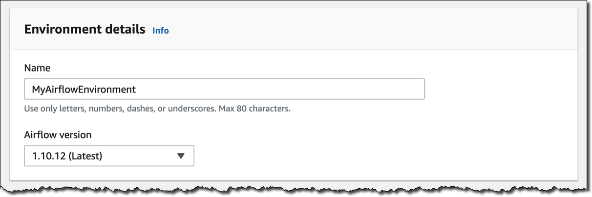
In the Amazon MWAA console, I click on Create environment. I give the environment a name and select the Airflow version to use.

Then, I select the S3 bucket and the folder to load my DAG code. The bucket name must start with airflow-.

Optionally, I can specify a plugins file and a requirements file:

  • The plugins file is a ZIP file containing the plugins used by my DAGs.
  • The requirements file describes the Python dependencies to run my DAGs.

For plugins and requirements, I can select the S3 object version to use. In case the plugins or the requirements I use create a non-recoverable error in my environment, Amazon MWAA will automatically roll back to the previous working version.


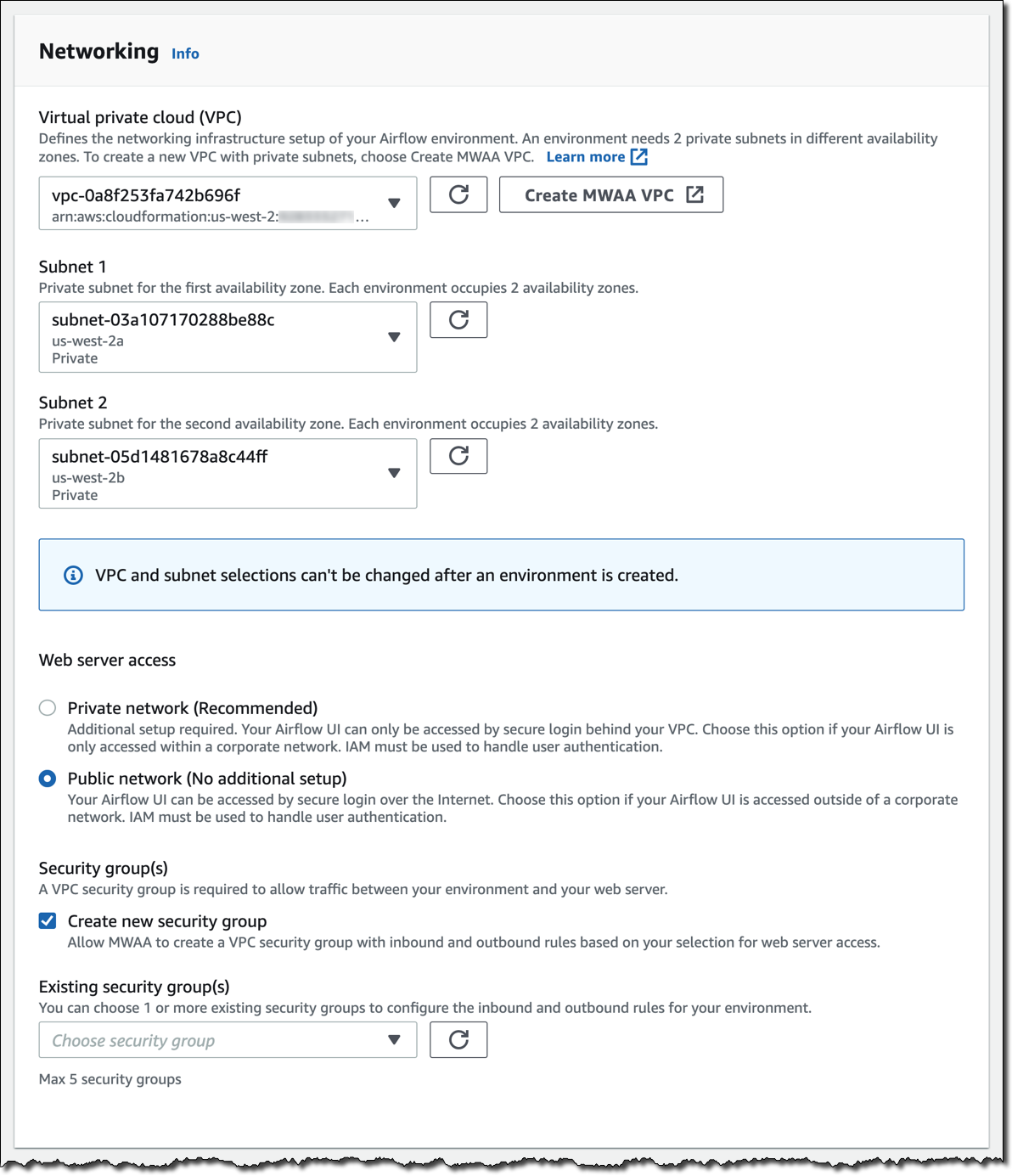
I click Next to configure the advanced settings, starting with networking. Each environment runs in a Amazon Virtual Private Cloud using private subnets in two availability zones. Web server access to the Airflow UI is always protected by a secure login using AWS Identity and Access Management (IAM). However, you can choose to have web server access on a public network so that you can login over the Internet, or on a private network in your VPC. For simplicity, I select a Public network. I let Amazon MWAA create a new security group with the correct inbound and outbound rules. Optionally, I can add one or more existing security groups to fine-tune control of inbound and outbound traffic for your environment.

Now, I configure my environment class. Each environment includes a scheduler, a web server, and a worker. Workers automatically scale up and down according to my workload. We provide you a suggestion on which class to use based on the number of DAGs, but you can monitor the load on your environment and modify its class at any time.

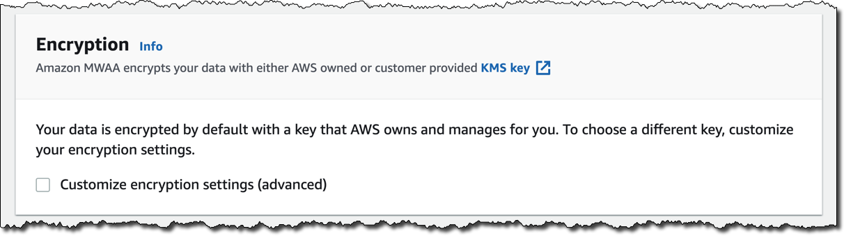
Encryption is always enabled for data at rest, and while I can select a customized key managed by AWS Key Management Service (KMS) I will instead keep the default key that AWS owns and manages on my behalf.

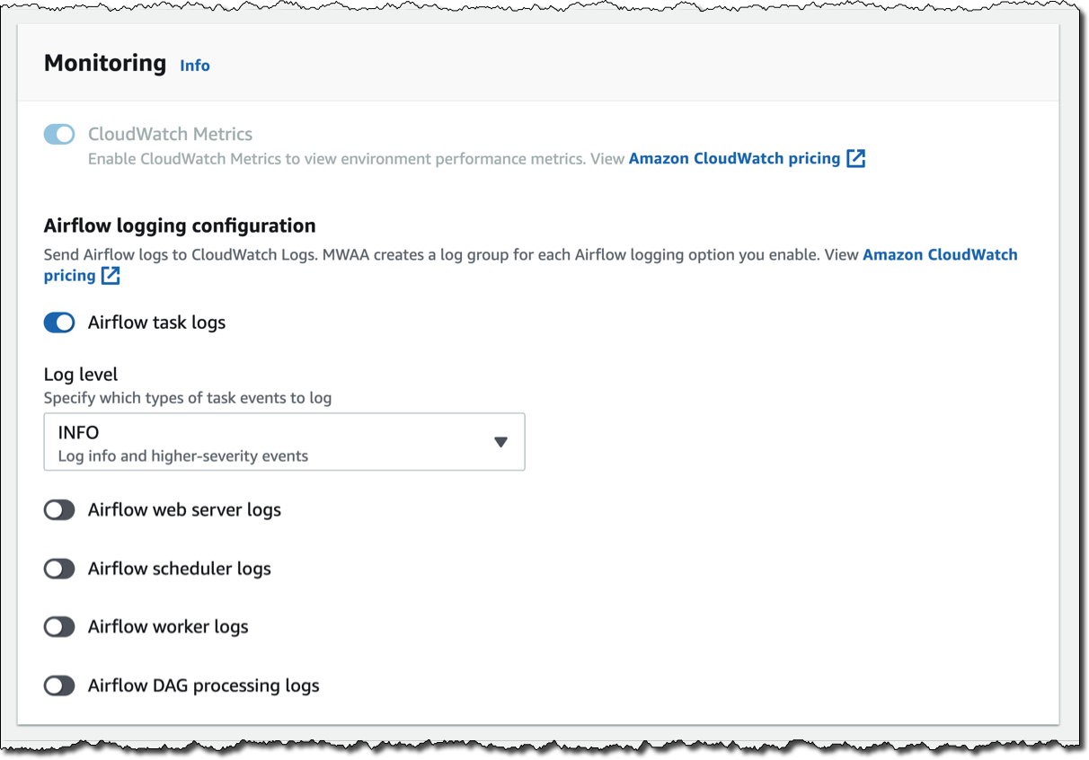
For monitoring, I publish environment performance to CloudWatch Metrics. This is enabled by default, but I can disable CloudWatch Metrics after launch. For the logs, I can specify the log level and which Airflow components should send their logs to CloudWatch Logs. I leave the default to send only the task logs and use log level INFO.

I can modify the default settings for Airflow configuration options, such as default_task_retries or worker_concurrency. For now, I am not changing these values.

Finally, but most importantly, I configure the permissions that will be used by my environment to access my DAGs, write logs, and run DAGs accessing other AWS resources. I select Create a new role and click on Create environment. After a few minutes, the new Airflow environment is ready to be used.

Using the Airflow UI
In the Amazon MWAA console, I look for the new environment I just created and click on Open Airflow UI. A new browser window is created and I am authenticated with a secure login via AWS IAM.

There, I look for a DAG that I put on S3 in the movie_list_dag.py file. The DAG is downloading the MovieLens dataset, processing the files on S3 using Amazon Athena, and loading the result to a Redshift cluster, creating the table if missing.

Here’s the full source code of the DAG:

from airflow import DAG
from airflow.operators.python_operator import PythonOperator
from airflow.operators import HttpSensor, S3KeySensor
from airflow.contrib.operators.aws_athena_operator import AWSAthenaOperator
from airflow.utils.dates import days_ago
from datetime import datetime, timedelta
from io import StringIO
from io import BytesIO
from time import sleep
import csv
import requests
import json
import boto3
import zipfile
import io
s3_bucket_name = 'my-bucket'
s3_key='files/'
redshift_cluster='redshift-cluster-1'
redshift_db='dev'
redshift_dbuser='awsuser'
redshift_table_name='movie_demo'
test_http='https://grouplens.org/datasets/movielens/latest/'
download_http='http://files.grouplens.org/datasets/movielens/ml-latest-small.zip'
athena_db='demo_athena_db'
athena_results='athena-results/'
create_athena_movie_table_query="""
CREATE EXTERNAL TABLE IF NOT EXISTS Demo_Athena_DB.ML_Latest_Small_Movies (
  `movieId` int,
  `title` string,
  `genres` string 
)
ROW FORMAT SERDE 'org.apache.hadoop.hive.serde2.lazy.LazySimpleSerDe'
WITH SERDEPROPERTIES (
  'serialization.format' = ',',
  'field.delim' = ','
) LOCATION 's3://pinwheeldemo1-pinwheeldagsbucketfeed0594-1bks69fq0utz/files/ml-latest-small/movies.csv/ml-latest-small/'
TBLPROPERTIES (
  'has_encrypted_data'='false',
  'skip.header.line.count'='1'
); 
"""
create_athena_ratings_table_query="""
CREATE EXTERNAL TABLE IF NOT EXISTS Demo_Athena_DB.ML_Latest_Small_Ratings (
  `userId` int,
  `movieId` int,
  `rating` int,
  `timestamp` bigint 
)
ROW FORMAT SERDE 'org.apache.hadoop.hive.serde2.lazy.LazySimpleSerDe'
WITH SERDEPROPERTIES (
  'serialization.format' = ',',
  'field.delim' = ','
) LOCATION 's3://pinwheeldemo1-pinwheeldagsbucketfeed0594-1bks69fq0utz/files/ml-latest-small/ratings.csv/ml-latest-small/'
TBLPROPERTIES (
  'has_encrypted_data'='false',
  'skip.header.line.count'='1'
); 
"""
create_athena_tags_table_query="""
CREATE EXTERNAL TABLE IF NOT EXISTS Demo_Athena_DB.ML_Latest_Small_Tags (
  `userId` int,
  `movieId` int,
  `tag` int,
  `timestamp` bigint 
)
ROW FORMAT SERDE 'org.apache.hadoop.hive.serde2.lazy.LazySimpleSerDe'
WITH SERDEPROPERTIES (
  'serialization.format' = ',',
  'field.delim' = ','
) LOCATION 's3://pinwheeldemo1-pinwheeldagsbucketfeed0594-1bks69fq0utz/files/ml-latest-small/tags.csv/ml-latest-small/'
TBLPROPERTIES (
  'has_encrypted_data'='false',
  'skip.header.line.count'='1'
); 
"""
join_tables_athena_query="""
SELECT REPLACE ( m.title , '"' , '' ) as title, r.rating
FROM demo_athena_db.ML_Latest_Small_Movies m
INNER JOIN (SELECT rating, movieId FROM demo_athena_db.ML_Latest_Small_Ratings WHERE rating > 4) r on m.movieId = r.movieId
"""
def download_zip():
    s3c = boto3.client('s3')
    indata = requests.get(download_http)
    n=0
    with zipfile.ZipFile(io.BytesIO(indata.content)) as z:       
        zList=z.namelist()
        print(zList)
        for i in zList: 
            print(i) 
            zfiledata = BytesIO(z.read(i))
            n += 1
            s3c.put_object(Bucket=s3_bucket_name, Key=s3_key+i+'/'+i, Body=zfiledata)
def clean_up_csv_fn(**kwargs):    
    ti = kwargs['task_instance']
    queryId = ti.xcom_pull(key='return_value', task_ids='join_athena_tables' )
    print(queryId)
    athenaKey=athena_results+"join_athena_tables/"+queryId+".csv"
    print(athenaKey)
    cleanKey=athena_results+"join_athena_tables/"+queryId+"_clean.csv"
    s3c = boto3.client('s3')
    obj = s3c.get_object(Bucket=s3_bucket_name, Key=athenaKey)
    infileStr=obj['Body'].read().decode('utf-8')
    outfileStr=infileStr.replace('"e"', '') 
    outfile = StringIO(outfileStr)
    s3c.put_object(Bucket=s3_bucket_name, Key=cleanKey, Body=outfile.getvalue())
def s3_to_redshift(**kwargs):    
    ti = kwargs['task_instance']
    queryId = ti.xcom_pull(key='return_value', task_ids='join_athena_tables' )
    print(queryId)
    athenaKey='s3://'+s3_bucket_name+"/"+athena_results+"join_athena_tables/"+queryId+"_clean.csv"
    print(athenaKey)
    sqlQuery="copy "+redshift_table_name+" from '"+athenaKey+"' iam_role 'arn:aws:iam::163919838948:role/myRedshiftRole' CSV IGNOREHEADER 1;"
    print(sqlQuery)
    rsd = boto3.client('redshift-data')
    resp = rsd.execute_statement(
        ClusterIdentifier=redshift_cluster,
        Database=redshift_db,
        DbUser=redshift_dbuser,
        Sql=sqlQuery
    )
    print(resp)
    return "OK"
def create_redshift_table():
    rsd = boto3.client('redshift-data')
    resp = rsd.execute_statement(
        ClusterIdentifier=redshift_cluster,
        Database=redshift_db,
        DbUser=redshift_dbuser,
        Sql="CREATE TABLE IF NOT EXISTS "+redshift_table_name+" (title	character varying, rating	int);"
    )
    print(resp)
    return "OK"
DEFAULT_ARGS = {
    'owner': 'airflow',
    'depends_on_past': False,
    'email': ['[email protected]'],
    'email_on_failure': False,
    'email_on_retry': False 
}
with DAG(
    dag_id='movie-list-dag',
    default_args=DEFAULT_ARGS,
    dagrun_timeout=timedelta(hours=2),
    start_date=days_ago(2),
    schedule_interval='*/10 * * * *',
    tags=['athena','redshift'],
) as dag:
    check_s3_for_key = S3KeySensor(
        task_id='check_s3_for_key',
        bucket_key=s3_key,
        wildcard_match=True,
        bucket_name=s3_bucket_name,
        s3_conn_id='aws_default',
        timeout=20,
        poke_interval=5,
        dag=dag
    )
    files_to_s3 = PythonOperator(
        task_id="files_to_s3",
        python_callable=download_zip
    )
    create_athena_movie_table = AWSAthenaOperator(task_id="create_athena_movie_table",query=create_athena_movie_table_query, database=athena_db, output_location='s3://'+s3_bucket_name+"/"+athena_results+'create_athena_movie_table')
    create_athena_ratings_table = AWSAthenaOperator(task_id="create_athena_ratings_table",query=create_athena_ratings_table_query, database=athena_db, output_location='s3://'+s3_bucket_name+"/"+athena_results+'create_athena_ratings_table')
    create_athena_tags_table = AWSAthenaOperator(task_id="create_athena_tags_table",query=create_athena_tags_table_query, database=athena_db, output_location='s3://'+s3_bucket_name+"/"+athena_results+'create_athena_tags_table')
    join_athena_tables = AWSAthenaOperator(task_id="join_athena_tables",query=join_tables_athena_query, database=athena_db, output_location='s3://'+s3_bucket_name+"/"+athena_results+'join_athena_tables')
    create_redshift_table_if_not_exists = PythonOperator(
        task_id="create_redshift_table_if_not_exists",
        python_callable=create_redshift_table
    )
    clean_up_csv = PythonOperator(
        task_id="clean_up_csv",
        python_callable=clean_up_csv_fn,
        provide_context=True     
    )
    transfer_to_redshift = PythonOperator(
        task_id="transfer_to_redshift",
        python_callable=s3_to_redshift,
        provide_context=True     
    )
    check_s3_for_key >> files_to_s3 >> create_athena_movie_table >> join_athena_tables >> clean_up_csv >> transfer_to_redshift
    files_to_s3 >> create_athena_ratings_table >> join_athena_tables
    files_to_s3 >> create_athena_tags_table >> join_athena_tables
    files_to_s3 >> create_redshift_table_if_not_exists >> transfer_to_redshift

In the code, different tasks are created using operators like PythonOperator, for generic Python code, or AWSAthenaOperator, to use the integration with Amazon Athena. To see how those tasks are connected in the workflow, you can see the latest few lines, that I repeat here (without indentation) for simplicity:

check_s3_for_key >> files_to_s3 >> create_athena_movie_table >> join_athena_tables >> clean_up_csv >> transfer_to_redshift
files_to_s3 >> create_athena_ratings_table >> join_athena_tables
files_to_s3 >> create_athena_tags_table >> join_athena_tables
files_to_s3 >> create_redshift_table_if_not_exists >> transfer_to_redshift

The Airflow code is overloading the right shift >> operator in Python to create a dependency, meaning that the task on the left should be executed first, and the output passed to the task on the right. Looking at the code, this is quite easy to read. Each of the four lines above is adding dependencies, and they are all evaluated together to execute the tasks in the right order.

In the Airflow console, I can see a graph view of the DAG to have a clear representation of how tasks are executed:

Available Now
Amazon Managed Workflows for Apache Airflow (MWAA) is available today in US East (Northern Virginia), US West (Oregon), US East (Ohio), Asia Pacific (Singapore), Asia Pacific (Toyko), Asia Pacific (Sydney), Europe (Ireland), Europe (Frankfurt), and Europe (Stockholm). You can launch a new Amazon MWAA environment from the console, AWS Command Line Interface (CLI), or AWS SDKs. Then, you can develop workflows in Python using Airflow’s ecosystem of integrations.

With Amazon MWAA, you pay based on the environment class and the workers you use. For more information, see the pricing page.

Upstream compatibility is a core tenet of Amazon MWAA. Our code changes to the AirFlow platform are released back to open source.

With Amazon MWAA you can spend more time building workflows for your engineering and data science tasks, and less time managing and scaling the infrastructure of your Airflow platform.

Learn more about Amazon MWAA and get started today!

Danilo

New – Archive and Replay Events with Amazon EventBridge

Post Syndicated from Danilo Poccia original https://aws.amazon.com/blogs/aws/new-archive-and-replay-events-with-amazon-eventbridge/

Event-driven architectures use events to share information between the components of one or more applications. Events tell us that “something has happened”, maybe you received an API request, a file has been uploaded to a storage platform, or a database record has been updated. Business events describe something related to your activities, for example that […]

Building Serverless Land: Part 1 – Automating content aggregation

Post Syndicated from Benjamin Smith original https://aws.amazon.com/blogs/compute/building-serverless-land-part-1-automating-content-aggregation/

In this two part blog series, I show how serverlessland.com is built. This is a static website that brings together all the latest blogs, videos, and training for AWS Serverless. It automatically aggregates content from a number of sources. The content exists in static JSON files, which generate a new site build each time they are updated. The result is a low-maintenance, low-latency serverless website, with almost limitless scalability.

This blog post explains how to automate the aggregation of content from multiple RSS feeds into a JSON file stored in GitHub. This workflow uses AWS Lambda and AWS Step Functions, triggered by Amazon EventBridge. The application can be downloaded and deployed from this GitHub repository.

The growing adoption of serverless technologies generates increasing amounts of helpful and insightful content from the developer community. This content can be difficult to discover. Serverless Land helps channel this into a single searchable location. By automating the collection of this content with scheduled serverless workflows, the process robustly scales to near infinite numbers. The Step Functions MAP state allows for dynamic parallel processing of multiple content sources, without the need to alter code. On-boarding a new content source is as fast and simple as making a single CLI command.

The architecture

Automating content aggregation with AWS Step Functions

The application consists of six Lambda functions orchestrated by a Step Functions workflow:

  1. The workflow is triggered every 2 hours by an EventBridge scheduler. The schedule event passes an RSS feed URL to the workflow.
  2. The first task invokes a Lambda function that runs an HTTP GET request to the RSS feed. It returns an array of recent blog URLs. The array of blog URLs is provided as the input to a MAP state. The MAP state type makes it possible to run a set of steps for each element of an input array in parallel. The number of items in the array can be different for each execution. This is referred to as dynamic parallelism.
  3. The next task invokes a Lambda function that uses the GitHub REST API to retrieve the static website’s JSON content file.
  4. The first Lambda function in the MAP state runs an HTTP GET request to the blog post URL provided in the payload. The URL is scraped for content and an object containing detailed metadata about the blog post is returned in the response.
  5. The blog post metadata is compared against the website’s JSON content file in GitHub.
  6. A CHOICE state determines if the blog post metadata has already been committed to the repository.
  7. If the blog post is new, it is added to an array of “content to commit”.
  8. As the workflow exits the MAP state, the results are passed to the final Lambda function. This uses a single git commit to add each blog post object to the website’s JSON content file in GitHub. This triggers an event that rebuilds the static site.

Using Secrets in AWS Lambda

Two of the Lambda functions require a GitHub personal access token to commit files to a repository. Sensitive credentials or secrets such as this should be stored separate to the function code. Use AWS Systems Manager Parameter Store to store the personal access token as an encrypted string. The AWS Serverless Application Model (AWS SAM) template grants each Lambda function permission to access and decrypt the string in order to use it.

  1. Follow these steps to create a personal access token that grants permission to update files to repositories in your GitHub account.
  2. Use the AWS Command Line Interface (AWS CLI) to create a new parameter named GitHubAPIKey:
aws ssm put-parameter \
--name /GitHubAPIKey \
--value ReplaceThisWithYourGitHubAPIKey \
--type SecureString

{
    "Version": 1,
    "Tier": "Standard"
}

Deploying the application

  1. Fork this GitHub repository to your GitHub Account.
  2. Clone the forked repository to your local machine and deploy the application using AWS SAM.
  3. In a terminal, enter:
    git clone https://github.com/aws-samples/content-aggregator-example
    sam deploy -g
  4. Enter the required parameters when prompted.

This deploys the application defined in the AWS SAM template file (template.yaml).

The business logic

Each Lambda function is written in Node.js and is stored inside a directory that contains the package dependencies in a `node_modules` folder. These are defined for each function by its relative package.json file. The function dependencies are bundled and deployed using the sam build && deploy -g command.

The GetRepoContents and WriteToGitHub Lambda functions use the octokit/rest.js library to communicate with GitHub. The library authenticates to GitHub by using the GitHub API key held in Parameter Store. The AWS SDK for Node.js is used to obtain the API key from Parameter Store. With a single synchronous call, it retrieves and decrypts the parameter value. This is then used to authenticate to GitHub.

const AWS = require('aws-sdk');
const SSM = new AWS.SSM();


//get Github API Key and Authenticate
    const singleParam = { Name: '/GitHubAPIKey ',WithDecryption: true };
    const GITHUB_ACCESS_TOKEN = await SSM.getParameter(singleParam).promise();
    const octokit = await  new Octokit({
      auth: GITHUB_ACCESS_TOKEN.Parameter.Value,
    })

Lambda environment variables are used to store non-sensitive key value data such as the repository name and JSON file location. These can be entered when deploying with AWS SAM guided deploy command.

Environment:
        Variables:
          GitHubRepo: !Ref GitHubRepo
          JSONFile: !Ref JSONFile

The GetRepoContents function makes a synchronous HTTP request to the GitHub repository to retrieve the contents of the website’s JSON file. The response SHA and file contents are returned from the Lambda function and acts as the input to the next task in the Step Functions workflow. This SHA is used in final step of the workflow to save all new blog posts in a single commit.

Map state iterations

The MAP state runs concurrently for each element in the input array (each blog post URL).

Each iteration must compare a blog post URL to the existing JSON content file and decide whether to ignore the post. To do this, the MAP state requires both the input array of blog post URLs and the existing JSON file contents. The ItemsPath, ResultPath, and Parameters are used to achieve this:

  • The ItemsPath sets input array path to $.RSSBlogs.body.
  • The ResultPath states that the output of the branches is placed in $.mapResults.
  • The Parameters block replaces the input to the iterations with a JSON node. This contains both the current item data from the context object ($$.Map.Item.Value) and the contents of the GitHub JSON file ($.RepoBlogs).
"Type":"Map",
    "InputPath": "$",
    "ItemsPath": "$.RSSBlogs.body",
    "ResultPath": "$.mapResults",
    "Parameters": {
        "BlogUrl.$": "$$.Map.Item.Value",
        "RepoBlogs.$": "$.RepoBlogs"
     },
    "MaxConcurrency": 0,
    "Iterator": {
       "StartAt": "getMeta",

The Step Functions resource

The AWS SAM template uses the following Step Functions resource definition to create a Step Functions state machine:

  MyStateMachine:
    Type: AWS::Serverless::StateMachine
    Properties:
      DefinitionUri: statemachine/my_state_machine.asl.JSON
      DefinitionSubstitutions:
        GetBlogPostArn: !GetAtt GetBlogPost.Arn
        GetUrlsArn: !GetAtt GetUrls.Arn
        WriteToGitHubArn: !GetAtt WriteToGitHub.Arn
        CompareAgainstRepoArn: !GetAtt CompareAgainstRepo.Arn
        GetRepoContentsArn: !GetAtt GetRepoContents.Arn
        AddToListArn: !GetAtt AddToList.Arn
      Role: !GetAtt StateMachineRole.Arn

The actual workflow definition is defined in a separate file (statemachine/my_state_machine.asl.JSON). The DefinitionSubstitutions property specifies mappings for placeholder variables. This enables the template to inject Lambda function ARNs obtained by the GetAtt intrinsic function during template translation:

Step Functions mappings with placeholder variables

A state machine execution role is defined within the AWS SAM template. It grants the `Lambda invoke function` action. This is tightly scoped to the six Lambda functions that are used in the workflow. It is the minimum set of permissions required for the Step Functions to carry out its task. Additional permissions can be granted as necessary, which follows the zero-trust security model.

Action: lambda:InvokeFunction
Resource:
- !GetAtt GetBlogPost.Arn
- !GetAtt GetUrls.Arn
- !GetAtt CompareAgainstRepo.Arn
- !GetAtt WriteToGitHub.Arn
- !GetAtt AddToList.Arn
- !GetAtt GetRepoContents.Arn

The Step Functions workflow definition is authored using the AWS Toolkit for Visual Studio Code. The Step Functions support allows developers to quickly generate workflow definitions from selectable examples. The render tool and automatic linting can help you debug and understand the workflow during development. Read more about the toolkit in this launch post.

Scheduling events and adding new feeds

The AWS SAM template creates a new EventBridge rule on the default event bus. This rule is scheduled to invoke the Step Functions workflow every 2 hours. A valid JSON string containing an RSS feed URL is sent as the input payload. The feed URL is obtained from a template parameter and can be set on deployment. The AWS Compute Blog is set as the default feed URL. To aggregate additional blog feeds, create a new rule to invoke the Step Functions workflow. Provide the RSS feed URL as valid JSON input string in the following format:

{“feedUrl”:”replace-this-with-your-rss-url”}

ScheduledEventRule:
    Type: "AWS::Events::Rule"
    Properties:
      Description: "Scheduled event to trigger Step Functions state machine"
      ScheduleExpression: rate(2 hours)
      State: "ENABLED"
      Targets:
        -
          Arn: !Ref MyStateMachine
          Id: !GetAtt MyStateMachine.Name
          RoleArn: !GetAtt ScheduledEventIAMRole.Arn
          Input: !Sub
            - >
              {
                "feedUrl" : "${RssFeedUrl}"
              }
            - RssFeedUrl: !Ref RSSFeed

A completed workflow with step output

Conclusion

This blog post shows how to automate the aggregation of content from multiple RSS feeds into a single JSON file using serverless workflows.

The Step Functions MAP state allows for dynamic parallel processing of each item. The recent increase in state payload size limit means that the contents of the static JSON file can be held within the workflow context. The application decision logic is separated from the business logic and events.

Lambda functions are scoped to finite business logic with Step Functions states managing decision logic and iterations. EventBridge is used to manage the inbound business events. The zero-trust security model is followed with minimum permissions granted to each service and Parameter Store used to hold encrypted secrets.

This application is used to pull together articles for http://serverlessland.com. Serverless land brings together all the latest blogs, videos, and training for AWS Serverless. Download the code from this GitHub repository to start building your own automated content aggregation platform.