Tag Archives: Front-End Web & Mobile

Level up your React app with Amazon QuickSight: How to embed your dashboard for anonymous access

Post Syndicated from Adrianna Kurzela original https://aws.amazon.com/blogs/big-data/level-up-your-react-app-with-amazon-quicksight-how-to-embed-your-dashboard-for-anonymous-access/

Using embedded analytics from Amazon QuickSight can simplify the process of equipping your application with functional visualizations without any complex development. There are multiple ways to embed QuickSight dashboards into application. In this post, we look at how it can be done using React and the Amazon QuickSight Embedding SDK.

Dashboard consumers often don’t have a user assigned to their AWS account and therefore lack access to the dashboard. To enable them to consume data, the dashboard needs to be accessible for anonymous users. Let’s look at the steps required to enable an unauthenticated user to view your QuickSight dashboard in your React application.

Solution overview

Our solution uses the following key services:

After loading the web page on the browser, the browser makes a call to API Gateway, which invokes a Lambda function that calls the QuickSight API to generate a dashboard URL for an anonymous user. The Lambda function needs to assume an IAM role with the required permissions. The following diagram shows an overview of the architecture.

Architecture

Prerequisites

You must have the following prerequisites:

Set up permissions for unauthenticated viewers

In your account, create an IAM policy that your application will assume on behalf of the viewer:

  1. On the IAM console, choose Policies in the navigation pane.
  2. Choose Create policy.
  3. On the JSON tab, enter the following policy code:
{
    "Version": "2012-10-17",
    "Statement": [
        {
            "Action": [
                "quicksight:GenerateEmbedUrlForAnonymousUser"
            ],
            "Resource": [
                "arn:aws:quicksight:*:*:namespace/default",
				"arn:aws:quicksight:*:*:dashboard/<YOUR_DASHBOARD_ID1>",
				"arn:aws:quicksight:*:*:dashboard/<YOUR_DASHBOARD_ID2>"
            ],
            "Effect": "Allow"
        },
        {
            "Action": [
                "logs:CreateLogGroup",
                "logs:CreateLogStream",
                "logs:PutLogEvents"
            ],
            "Resource": "*",
            "Effect": "Allow"
        }
    ]
}

Make sure to change the value of <YOUR_DASHBOARD_ID> to the value of the dashboard ID. Note this ID to use in a later step as well.

For the second statement object with logs, permissions are optional. It allows you to create a log group with the specified name, create a log stream for the specified log group, and upload a batch of log events to the specified log stream.

In this policy, we allow the user to perform the GenerateEmbedUrlForAnonymousUser action on the dashboard ID within the list of dashboard IDs inserted in the placeholder.

  1. Enter a name for your policy (for example, AnonymousEmbedPolicy) and choose Create policy.

Next, we create a role and attach this policy to the role.

  1. Choose Roles in the navigation pane, then choose Create role.

Identity and access console

  1. Choose Lambda for the trusted entity.
  2. Search for and select AnonymousEmbedPolicy, then choose Next.
  3. Enter a name for your role, such as AnonymousEmbedRole.
  4. Make sure the policy name is included in the Add permissions section.
  5. Finish creating your role.

You have just created the AnonymousEmbedRole execution role. You can now move to the next step.

Generate an anonymous embed URL Lambda function

In this step, we create a Lambda function that interacts with QuickSight to generate an embed URL for an anonymous user. Our domain needs to be allowed. There are two ways to achieve the integration of Amazon QuickSight:

  1. By adding the URL to the list of allowed domains in the Amazon QuickSight admin console (explained later in [Optional] Add your domain in QuickSight section).
  2. [Recommended] By adding the embed URL request during runtime in the API call. Option 1 is recommended when you need to persist the allowed domains. Otherwise, the domains will be removed after 30 minutes, which is equivalent to the session duration. For other use cases, it is recommended to use the second option (described and implemented below).

On the Lambda console, create a new function.

  1. Select Author from scratch.
  2. For Function name, enter a name, such as AnonymousEmbedFunction.
  3. For Runtime¸ choose Python 3.9.
  4. For Execution role¸ choose Use an existing role.
  5. Choose the role AnonymousEmbedRole.
  6. Choose Create function.
  7. On the function details page, navigate to the Code tab and enter the following code:

import json, boto3, os, re, base64

def lambda_handler(event, context):
print(event)
try:
def getQuickSightDashboardUrl(awsAccountId, dashboardIdList, dashboardRegion, event):
#Create QuickSight client
quickSight = boto3.client('quicksight', region_name=dashboardRegion);

#Construct dashboardArnList from dashboardIdList
dashboardArnList=[ 'arn:aws:quicksight:'+dashboardRegion+':'+awsAccountId+':dashboard/'+dashboardId for dashboardId in dashboardIdList]
#Generate Anonymous Embed url
response = quickSight.generate_embed_url_for_anonymous_user(
AwsAccountId = awsAccountId,
Namespace = 'default',
ExperienceConfiguration = {'Dashboard':{'InitialDashboardId': dashboardIdList[0]}},
AuthorizedResourceArns = dashboardArnList,
SessionLifetimeInMinutes = 60,
AllowedDomains = ['http://localhost:3000']
)
return response

#Get AWS Account Id
awsAccountId = context.invoked_function_arn.split(':')[4]

#Read in the environment variables
dashboardIdList = re.sub(' ','',os.environ['DashboardIdList']).split(',')
dashboardNameList = os.environ['DashboardNameList'].split(',')
dashboardRegion = os.environ['DashboardRegion']

response={}

response = getQuickSightDashboardUrl(awsAccountId, dashboardIdList, dashboardRegion, event)

return {'statusCode':200,
'headers': {"Access-Control-Allow-Origin": "http://localhost:3000",
"Content-Type":"text/plain"},
'body':json.dumps(response)
}

except Exception as e: #catch all
return {'statusCode':400,
'headers': {"Access-Control-Allow-Origin": "http://localhost:3000",
"Content-Type":"text/plain"},
'body':json.dumps('Error: ' + str(e))
}

If you don’t use localhost, replace http://localhost:3000 in the returns with the hostname of your application. To move to production, don’t forget to replace http://localhost:3000 with your domain.

  1. On the Configuration tab, under General configuration, choose Edit.
  2. Increase the timeout from 3 seconds to 30 seconds, then choose Save.
  3. Under Environment variables, choose Edit.
  4. Add the following variables:
    1. Add DashboardIdList and list your dashboard IDs.
    2. Add DashboardRegion and enter the Region of your dashboard.
  5. Choose Save.

Your configuration should look similar to the following screenshot.

  1. On the Code tab, choose Deploy to deploy the function.

Environment variables console

Set up API Gateway to invoke the Lambda function

To set up API Gateway to invoke the function you created, complete the following steps:

  1. On the API Gateway console, navigate to the REST API section and choose Build.
  2. Under Create new API, select New API.
  3. For API name, enter a name (for example, QuicksightAnonymousEmbed).
  4. Choose Create API.

API gateway console

  1. On the Actions menu, choose Create resource.
  2. For Resource name, enter a name (for example, anonymous-embed).

Now, let’s create a method.

  1. Choose the anonymous-embed resource and on the Actions menu, choose Create method.
  2. Choose GET under the resource name.
  3. For Integration type, select Lambda.
  4. Select Use Lambda Proxy Integration.
  5. For Lambda function, enter the name of the function you created.
  6. Choose Save, then choose OK.

API gateway console

Now we’re ready to deploy the API.

  1. On the Actions menu, choose Deploy API.
  2. For Deployment stage, select New stage.
  3. Enter a name for your stage, such as embed.
  4. Choose Deploy.

[Optional] Add your domain in QuickSight

If you added Allowed domains in Generate an anonymous embed URL Lambda function part, feel free to move to Turn on capacity pricing section.

To add your domain to the allowed domains in QuickSight, complete the following steps:

  1. On the QuickSight console, choose the user menu, then choose Manage QuickSight.

Quicksight dropdown menu

  1. Choose Domains and Embedding in the navigation pane.
  2. For Domain, enter your domain (http://localhost:<PortNumber>).

Make sure to replace <PortNumber> to match your local setup.

  1. Choose Add.

Quicksight admin console

Make sure to replace the localhost domain with the one you will use after testing.

Turn on capacity pricing

If you don’t have session capacity pricing enabled, follow the steps in this section. It’s mandatory to have this function enabled to proceed further.

Capacity pricing allows QuickSight customers to purchase reader sessions in bulk without having to provision individual readers in QuickSight. Capacity pricing is ideal for embedded applications or large-scale business intelligence (BI) deployments. For more information, visit Amazon QuickSight Pricing.

To turn on capacity pricing, complete the following steps:

  1. On the Manage QuickSight page, choose Your Subscriptions in the navigation pane.
  2. In the Capacity pricing section, select Get monthly subscription.
  3. Choose Confirm subscription.

To learn more about capacity pricing, see New in Amazon QuickSight – session capacity pricing for large scale deployments, embedding in public websites, and developer portal for embedded analytics.

Set up your React application

To set up your React application, complete the following steps:

  1. In your React project folder, go to your root directory and run npm i amazon-quicksight-embedding-sdk to install the amazon-quicksight-embedding-sdk package.
  2. In your App.js file, replace the following:
    1. Replace YOUR_API_GATEWAY_INVOKE_URL/RESOURCE_NAME with your API Gateway invoke URL and your resource name (for example, https://xxxxxxxx.execute-api.xx-xxx-x.amazonaws.com/embed/anonymous-embed).
    2. Replace YOUR_DASHBOARD1_ID with the first dashboardId from your DashboardIdList. This is the dashboard that will be shown on the initial render.
    3. Replace YOUR_DASHBOARD2_ID with the second dashboardId from your DashboardIdList.

The following code snippet shows an example of the App.js file in your React project. The code is a React component that embeds a QuickSight dashboard based on the selected dashboard ID. The code contains the following key components:

  • State hooks – Two state hooks are defined using the useState() hook from React:
    • dashboard – Holds the currently selected dashboard ID.
    • quickSightEmbedding – Holds the QuickSight embedding object returned by the embedDashboard() function.
  • Ref hook – A ref hook is defined using the useRef() hook from React. It’s used to hold a reference to the DOM element where the QuickSight dashboard will be embedded.
  • useEffect() hook – The useEffect() hook is used to trigger the embedding of the QuickSight dashboard whenever the selected dashboard ID changes. It first fetches the dashboard URL for the selected ID from the QuickSight API using the fetch() method. After it retrieves the URL, it calls the embed() function with the URL as the argument.
  • Change handler – The changeDashboard() function is a simple event handler that updates the dashboard state whenever the user selects a different dashboard from the drop-down menu. As soon as new dashboard ID is set, the useEffect hook is triggered.
  • 10-millisecond timeout – The purpose of using the timeout is to introduce a small delay of 10 milliseconds before making the API call. This delay can be useful in scenarios where you want to avoid immediate API calls or prevent excessive requests when the component renders frequently. The timeout gives the component some time to settle before initiating the API request. Because we’re building the application in development mode, the timeout helps avoid errors caused by the double run of useEffect within StrictMode. For more information, refer to Updates to Strict Mode.

See the following code:

import './App.css';
import * as React from 'react';
import { useEffect, useRef, useState } from 'react';
import { createEmbeddingContext } from 'amazon-quicksight-embedding-sdk';

 function App() {
  const dashboardRef = useRef([]);
  const [dashboardId, setDashboardId] = useState('YOUR_DASHBOARD1_ID');
  const [embeddedDashboard, setEmbeddedDashboard] = useState(null);
  const [dashboardUrl, setDashboardUrl] = useState(null);
  const [embeddingContext, setEmbeddingContext] = useState(null);

  useEffect(() => {
    const timeout = setTimeout(() => {
      fetch("YOUR_API_GATEWAY_INVOKE_URL/RESOURCE_NAME"
      ).then((response) => response.json()
      ).then((response) => {
        setDashboardUrl(response.EmbedUrl)
      })
    }, 10);
    return () => clearTimeout(timeout);
  }, []);

  const createContext = async () => {
    const context = await createEmbeddingContext();
    setEmbeddingContext(context);
  }

  useEffect(() => {
    if (dashboardUrl) { createContext() }
  }, [dashboardUrl])

  useEffect(() => {
    if (embeddingContext) { embed(); }
  }, [embeddingContext])

  const embed = async () => {

    const options = {
      url: dashboardUrl,
      container: dashboardRef.current,
      height: "500px",
      width: "600px",
    };

    const newEmbeddedDashboard = await embeddingContext.embedDashboard(options);
    setEmbeddedDashboard(newEmbeddedDashboard);
  };

  useEffect(() => {
    if (embeddedDashboard) {
      embeddedDashboard.navigateToDashboard(dashboardId, {})
    }
  }, [dashboardId])

  const changeDashboard = async (e) => {
    const dashboardId = e.target.value
    setDashboardId(dashboardId)
  }

  return (
    <>
      <header>
        <h1>Embedded <i>QuickSight</i>: Build Powerful Dashboards in React</h1>
      </header>
      <main>
        <p>Welcome to the QuickSight dashboard embedding sample page</p>
        <p>Please pick a dashboard you want to render</p>
        <select id='dashboard' value={dashboardId} onChange={changeDashboard}>
          <option value="YOUR_DASHBOARD1_ID">YOUR_DASHBOARD1_NAME</option>
          <option value="YOUR_DASHBOARD2_ID">YOUR_DASHBOARD2_NAME</option>
        </select>
        <div ref={dashboardRef} />
      </main>
    </>
  );
};

export default App

Next, replace the contents of your App.css file, which is used to style and layout your web page, with the content from the following code snippet:

body {
  background-color: #ffffff;
  font-family: Arial, sans-serif;
  margin: 0;
  padding: 0;
}

header {
  background-color: #f1f1f1;
  padding: 20px;
  text-align: center;
}

h1 {
  margin: 0;
}

main {
  margin: 20px;
  text-align: center;
}

p {
  margin-bottom: 20px;
}

a {
  color: #000000;
  text-decoration: none;
}

a:hover {
  text-decoration: underline;
}

i {
  color: orange;
  font-style: normal;
}

Now it’s time to test your app. Start your application by running npm start in your terminal. The following screenshots show examples of your app as well as the dashboards it can display.

Example application page with the visualisation

Example application page with the visualisation

Conclusion

In this post, we showed you how to embed a QuickSight dashboard into a React application using the AWS SDK. Sharing your dashboard with anonymous users allows them to access your dashboard without granting them access to your AWS account. There are also other ways to share your dashboard anonymously, such as using 1-click public embedding.

Join the Quicksight Community to ask, answer and learn with others and explore additional resources.


About the Author

author headshot

Adrianna is a Solutions Architect at AWS Global Financial Services. Having been a part of Amazon since August 2018, she has had the chance to be involved both in the operations as well as the cloud business of the company. Currently, she builds software assets which demonstrate innovative use of AWS services, tailored to a specific customer use cases. On a daily basis, she actively engages with various aspects of technology, but her true passion lies in combination of web development and analytics.

New Solution – Clickstream Analytics on AWS for Mobile and Web Applications

Post Syndicated from Sébastien Stormacq original https://aws.amazon.com/blogs/aws/new-solution-clickstream-analytics-on-aws-for-mobile-and-web-applications/

Starting today, you can deploy on your AWS account an end-to-end solution to capture, ingest, store, analyze, and visualize your customers’ clickstreams inside your web and mobile applications (both for Android and iOS). The solution is built on top of standard AWS services.

This new solution Clickstream Analytics on AWS allows you to keep your data in the security and compliance perimeter of your AWS account and customize the processing and analytics as you require, giving you the full flexibility to extract value for your business. For example, many business line owners want to combine clickstream analytics data with business system data to gain more comprehensive insights. Storing clickstream analysis data in your AWS account allows you to cross reference the data with your existing business system, which is complex to implement when you use a third-party analytics solution that creates an artificial data silo.

Clickstream Analytics on AWS is available from the AWS Solutions Library at no cost, except for the services it deploys on your account.

Why Analyze Your Applications Clickstreams?
Organizations today are in search of vetted solutions and architectural guidance to rapidly solve business challenges. Whether you prefer off-the-shelf deployments or customizable architectures, the AWS Solutions Library carries solutions built by AWS and AWS Partners for a broad range of industry and technology use cases.

When I talk with mobile and web application developers or product owners, you often tell me that you want to use a clickstream analysis solution to understand your customers’ behavior inside your application. Click stream analysis solutions help you to identify popular and frequently visited screens, analyze navigation patterns, identify bottlenecks and drop-off points, or perform A/B testing of functionalities such as the pay wall, but you face two challenges to adopt or build a click stream analysis solution.

Either you use a third-party library and analytics solution that sends all your application and customer data to an external provider, which causes security and compliance risks and makes it more difficult to reference your existing business data to enrich the analysis, or you dedicate time and resources to build your own solution based on AWS services, such as Amazon Kinesis (for data ingestion), Amazon EMR (for processing), Amazon Redshift (for storage), and Amazon QuickSight (for visualization). Doing so ensures your application and customer data stay in the security perimeter of your AWS account, which is already approved and vetted by your information and security team. Often, building such a solution is an undifferentiated task that drives resources and budget away from developing the core business of your application.

Introducing Clickstream Analytics on AWS
The new solution Clickstream Analytics on AWS provides you with a backend for data ingestion, processing, and visualization of click stream data. It’s shipped as an AWS CloudFormation template that you can easily deploy into the AWS account of your choice.

In addition to the backend component, the solution provides you with purpose-built Java and Swift SDKs to integrate into your mobile applications (for both Android and iOS). The SDKs automatically collects data and provide developers with an easy-to-use API to collect application-specific data. They manage the low-level tasks of buffering the data locally, sending them to the backend, managing the retries in case of communication errors, and more.

The following diagram shows you the high-level architecture of the solution.

Clickstream analysis - architecture

The solution comes with an easy-to-use console to configure your solution. For example, it allows you to choose between three AWS services to ingest the application clickstream data: Amazon Managed Streaming for Apache Kafka, Amazon Kinesis Data Streams, or Amazon Simple Storage Service (Amazon S3). You can create multiple data pipelines for multiple applications or teams, each using a different configuration. This allows you to adjust the backend to the application user base and requirements.

You can use plugins to transform the data during the processing phase. The solution comes with two plugins preinstalled: User-Agent enrichment and IP address enrichment to add additional data that’s related to the User-Agent and the geolocation of the IP address used by the client applications.

By default, it provides a Amazon Redshift Serverless cluster to minimize the costs, but you can select a provisioned Amazon Redshift configuration to meet your performance and budget requirements.

Finally, the solution provides you with a set of pre-assembled visualization dashboards to report on user acquisition, user activity, and user engagement. The dashboard consumes the data available in Amazon Redshift. You’re free to develop other analytics and other dashboards using the tools and services of your choice.

Let’s See It in Action
The best way to learn how to deploy and to configure Clickstream Analytics on AWS is to follow the tutorial steps provided by the Clickstream Analytics on AWS workshop.

The workshop goes into great detail about each step. Here are the main steps I did to deploy the solution:

1. I create the control plane (the management console) of the solution using this CloudFormation template. The output of the template contains the URL to the management console. I later receive an email with a temporary password for the initial connection.

2. On the Clickstream Analytics console, I create my first project and define various network parameters such as the VPC, subnets, and security groups. I also select the service to use for data ingestion and my choice of configuration for Amazon Redshift.

Clickstream analysis - Create project

Clickstream analysis - data sink

3. When I enter all configuration data, the console creates the data plane for my application.

AWS services and solutions are usually built around a control plane and one or multiple data planes. In the context of Clickstream Analytics, the control plane is the console that I use to define my data acquisition and analysis project. The data plane is the infrastructure to receive, analyze, and visualize my application data. Now that I define my project, the console generates and launches another CloudFormation template to create and manage the data plane.

4. The Clickstream Analytics console generates a JSON configuration file to include into my application and it shares the Java or Swift code to include into my Android or iOS application. The console provides instructions to add the clickstream analysis as a dependency to my application. I also update my application code to insert the code suggested and start to deploy.

Clickstream analysis - code for your applications

5. After my customers start to use the mobile app, I access the Clickstream Analytics dashboard to visualize the data collected.

The Dashboards
Clickstream Analytics dashboards are designed to provide a holistic view of the user lifecycle: the acquisition, the engagement, the activity, and the retention. In addition, it adds visibility into user devices and geographies. The solution automatically generates visualizations in these six categories: Acquisition, Engagement, Activity, Retention, Devices, and Navigation path. Here are a couple of examples.

The Acquisition dashboard reports the total number of users, the registered number of users (the ones that signed in), and the number of users by traffic source. It also computes the new users and registered users’ trends.

Clickstream analysis - acquisition dashboard

The Engagement dashboard reports the user engagement level (the number of user sessions versus the time users spent on my application). Specifically, I have access to the number of engaged sessions (sessions that last more than 10 seconds or have at least two screen views), the engagement rate (the percentage of engaged sessions from the total number of sessions), and the average engagement time.

Clickstream analysis - engagement dashboard

The Activity dashboard shows the event and actions taken by my customers in my application. It reports data, such as the number of events and number of views (or screens) shown, with the top events and views shown for a given amount of time.

Clickstream analysis - activity dashboard

The Retention tab shows user retention over time: the user stickiness for your daily, weekly, and monthly active users. It also shows the rate of returning users versus new users.

Clickstream analysis - retention

The Device tab shows data about your customer’s devices: operating systems, versions, screen sizes, and language.

Clickstream analysis - devices dashboard

And finally, the Path explorer dashboard shows your customers’ navigation path into the screens of your applications.

Clickstream analysis - path explorer dashboard

As I mentioned earlier, all the data are available in Amazon Redshift, so you’re free to build other analytics and dashboards.

Pricing and Availability
The Clickstream Analytics solution is available free of charge. You pay for the AWS services provisioned for you, including Kinesis or Amazon Redshift. Cost estimates depend on the configuration that you select. For example, the size of the Kinesis and Amazon Redshift cluster you select for your data ingestion and analytics needs, or the volume of data your applications send to the pipeline both affect the monthly cost of the solution.

To learn how to get started with this solution, take the Clickstream Analytics workshop today and stop sharing your customer and application clickstream data with third-party solutions.

— seb

AWS AppSync GraphQL APIs Supports JavaScript Resolvers

Post Syndicated from Marcia Villalba original https://aws.amazon.com/blogs/aws/aws-appsync-graphql-apis-supports-javascript-resolvers/

Starting today, AWS AppSync supports JavaScript resolvers and provides a resolver evaluation engine to test them before publishing them to the cloud.

AWS AppSync, launched in 2017, is a service that allows you to build, manage, and host GraphQL APIs in the cloud. AWS AppSync connects your GraphQL schema to different data sources using resolvers. Resolvers are how AWS AppSync translates GraphQL requests and fetches information from the different data sources.

Until today, many customers had to write their resolvers using Apache Velocity Template Language (VTL). To write VTL resolvers, many developers needed to learn a new language, and that discouraged them from taking advantage of the capabilities that resolvers offer. And when they did write them, developers faced the challenge of how to test the VTL resolvers. That is why many customers resorted to writing their complex resolvers as AWS Lambda functions and then creating a simple VTL resolver that invoked that function. This adds more complexity to their applications, as now they have to maintain and operate this new Lambda function.

AWS AppSync executes resolvers on a GraphQL field. Sometimes, applications require executing multiple operations to resolve a single GraphQL field. When using AWS AppSync, developers can create pipeline resolvers to compose operations (called functions) and execute them in sequence. Each function performs an operation over a data source, for example, fetching an item from an Amazon DynamoDB table.

How a function works

Introducing AWS AppSync JavaScript pipeline resolvers
Now, in addition to VTL, developers can use JavaScript to write their functions. You can mix functions written in JavaScript and VTL inside a pipeline resolver.

This new launch comes with two new NPM libraries to simplify development: @aws-appsync/eslint-plugin to catch and fix problems quickly during development and @aws-appsync/utils to provide type validation and autocompletion in code editors.

Developers can test their JavaScript code using AWS AppSync’s new API command, evaluate-code. During a test, the code is validated for correctness and evaluated with mock data. This helps developers validate their code before pushing their changes to the cloud.

With this launch, AWS AppSync becomes one of the easiest ways for your applications to talk to almost any AWS service. You can write an HTTP function that calls any AWS service with an API endpoint using JavaScript and use that function as part of your pipeline. For example, you can create a pipeline resolver that is invoked when a query on a GraphQL field occurs. This field returns the translated text in Spanish of an item stored in a table. This pipeline resolver is composed of two functions, one that fetches data from a DynamoDB table and one that uses Amazon Translate API to translate the item text into Spanish.

function awsTranslateRequest(Text, SourceLanguageCode, SourceLanguageCode) {
  return {
    method: 'POST',
    resourcePath: '/',
    params: {
      headers: {
        'content-type': 'application/x-amz-json-1.1',
        'x-amz-target': 'AWSShineFrontendService_20170701.TranslateText',
      },
      body: JSON.stringify({ Text, SourceLanguageCode, SourceLanguageCode }),
    },
  };
}

Getting started
You can create JavaScript functions from the AWS AppSync console or using the AWS Command Line Interface (CLI). Let’s create a pipeline resolver that gets an item from an existing DynamoDB table using the AWS CLI. This resolver only has one function.

When creating a new AWS AppSync function, you need to provide the code for that function. Create a new JavaScript file and copy the following code snippet.

import { util } from '@aws-appsync/utils';

/**
 * Request a single item from the attached DynamoDB table
 * @param ctx the request context
 */
export function request(ctx) {
  return {
    operation: 'GetItem',
    key: util.dynamodb.toMapValues({ id: ctx.args.id }),
  };
}

/**
 * Returns the DynamoDB result directly
 * @param ctx the request context
 */
export function response(ctx) {
  return ctx.result;
}

All functions need to have a request and response method, and in each of these methods, you can perform the operations for fulfilling the business need.

To get started, first make sure that you have the latest version of the AWS CLI, that you have a DynamoDB table created, and that you have an AWS AppSync API. Then you can create the function in AWS AppSync using the AWS CLI create-function command and the file you just created. This command returns the function ID. To create the resolver, pass the function ID, the GraphQL operation, and the field where you want to apply the resolver. In the documentation, you can find a detailed tutorial on how to create pipeline resolvers.

Testing a resolver
To test a function, use the evaluate-code command from AWS CLI or AWS SDK. This command calls the AWS AppSync service and evaluates the code with the provided context. To automate the test, you can use any JavaScript testing and assertion library. For example, the following code snippet uses Jest to validate the returned results programmatically.

import * as AWS from 'aws-sdk'
import { readFile } from 'fs/promises'
const appsync = new AWS.AppSync({ region: 'us-east-2' })
const file = './functions/updateItem.js'

test('validate an update request', async () => {
  const context = JSON.stringify({
    arguments: {
      input: { id: '<my-id>', title: 'change!', description: null },
    },
  })
  const code = await readFile(file, { encoding: 'utf8' })
  const runtime = { name: 'APPSYNC_JS', runtimeVersion: '1.0.0' }
  const params = { context, code, runtime, function: 'request' }

  const response = await appsync.evaluateCode(params).promise()
  expect(response.error).toBeUndefined()
  expect(response.evaluationResult).toBeDefined()
  const result = JSON.parse(response.evaluationResult)
  expect(result.key.id.S).toEqual(context.arguments.input.id)
  expect(result.update.expressionNames).not.toHaveProperty('#id')
  expect(result.update.expressionNames).toHaveProperty('#title')
  expect(result.update.expressionNames).toHaveProperty('#description')
  expect(result.update.expressionValues).not.toHaveProperty(':description')
})

In this way, you can add your API tests to your build process and validate that you coded the resolvers correctly before you push the changes to the cloud.

Get started today
The support for JavaScript AWS AppSync resolvers in AWS AppSync is available for all Regions that currently support AWS AppSync. You can start using this feature today from the AWS Management Console, AWS CLI, or Amazon CloudFormation.

Learn more about this launch by visiting the AWS AppSync service page.

Marcia

Let’s Architect! Architecting for front end

Post Syndicated from Luca Mezzalira original https://aws.amazon.com/blogs/architecture/lets-architect-architecting-for-front-end/

Many workloads in the cloud need a front-end interface for interacting with APIs, either for populating content or for consuming it. This edition of Let’s Architect! shows you how to scale your front-end applications and serve data across multiple devices.

Micro-frontend Architectures on AWS

Micro-frontends are the technical representation of a business subdomain, they allow independent implementations with the same or different technology.

They help minimize the code shared with other subdomains and are owned by a single team. This blog post shows you how to apply client-side rendering micro-frontends in AWS.

Microservices backend with the micro-frontends

Microservices backend with the micro-frontends

Building serverless micro frontends at the edge

Microservices architectures use techniques like canary releases or blue-green deployments to reduce the blastradius of issues deployed in production. In this video, you’ll learn how Ryanair scaled their front-end practice across their website and how to implement these techniques using Lambda@Edge and Amazon CloudFront.

A serverless architecture designed using AWS Step Functions for SEO integration of micro-frontends

A serverless architecture designed using AWS Step Functions for SEO integration of micro-frontends

Introduction to GraphQL

Many companies build APIs with GraphQL because it gives front-end developers the ability to query multiple databases, microservices, and APIs with a single GraphQL endpoint.

This video introduces asynchronous APIs, GraphQL, and the most common architectural patterns to work with. It also provides a starting point to understand the differences between REST and GraphQL as well as  mental models to identify the right tool for each job.

Some recommended practices to consider while getting a GraphQL API into production

Some recommended practices to consider while getting a GraphQL API into production

Mocking and Testing Serverless APIs with AWS Amplify

This video covers how to write successful tests against an API backend using AWS Amplify. Amplify speeds up the development of your front-end and serverless backend applications.

Thanks to its low-code approach, you can focus on writing the business logic of your applications without the need to create the plumbing between services. If you need to add more configurations using Amplify, review its custom resources.

The Amplify Command Line Interface (CLI) is a unified toolchain to create, integrate, and manage cloud services for your application

The Amplify Command Line Interface (CLI) is a unified toolchain to create, integrate, and manage cloud services for your application

See you next time!

Thanks for reading! See you in a couple of weeks when we discuss technological lock-in.

Other posts in this series

Looking for more architecture content?

AWS Architecture Center provides reference architecture diagrams, vetted architecture solutions, Well-Architected best practices, patterns, icons, and more!

Announcing the General Availability of AWS Amplify Studio

Post Syndicated from Steve Roberts original https://aws.amazon.com/blogs/aws/announcing-the-general-availability-of-aws-amplify-studio/

Amplify Studio is a visual interface that simplifies front- and backend development for web and mobile applications. We released it as a preview during AWS re:Invent 2021, and today, I’m happy to announce that it is now generally available (GA). A key feature of Amplify Studio is integration with Figma, helping designers and front-end developers to work collaboratively on design and development tasks. To stay in sync as designs change, developers simply pull the new component designs from Figma into their application in Amplify Studio. The GA version of Amplify Studio also includes some new features such as support for UI event handlers, component theming, and improvements in how you can extend and customize generated components from code.

You may be familiar with AWS Amplify, a set of tools and features to help developers get started faster with configuring various AWS services to support their backend use cases such as user authentication, real-time data, AI/ML, and file storage. Amplify Studio extends this ease of configuration to front-end developers, who can use it to work with prebuilt and custom rich user interface (UI) components for those applications. Backend developers can also make use of Amplify Studio to continue development and configuration of the application’s backend services.

Amplify Studio’s point-and-click visual environment enables front-end developers to quickly and easily compose user interfaces from a library of prebuilt and custom UI components. Components are themeable, enabling you to override Amplify Studio‘s default themes to customize components according to your own or your company’s style guides. Components can also be bound to backend services with no cloud or AWS expertise.

Support for developing the front- and backend tiers of an application isn’t all that’s available. From within Amplify Studio, developers can also take advantage of AWS Amplify Hosting services, Amplify‘s fully managed CI/CD and hosting service for scalable web apps. This service offers a zero-configuration way to deploy the application by simply connecting a Git repository with a built-in continuous integration and deployment workflow. Deployment artifacts can be exported to tools such as the AWS Cloud Development Kit (AWS CDK), making it easy to add support for other AWS services unavailable directly within Amplify Studio. In fact, all of the artifacts that are created in Amplify Studio can be exported as code for you to edit in the IDE of your choice.

You can read all about the original preview, and walk through an example of using Amplify Studio and Figma together, in this blog post published during re:Invent.

UI Event Handlers
Front-end developers are likely familiar with the concepts behind binding events on UI components to invoke some action. For example, selecting a button might cause a transition to another screen or populate some other field with data, potentially supplied from a backend service. In the following screenshot, we’re configuring an event handler for the onClick event on a Card component to open a new browser tab:

Setting a UI event binding

For the selected action we then define the settings, in this case to open a map view onto the location using the latitude and longitude in the card object’s model:

Setting the properties for the action

Extending Components with Code
When you pull your component designs from Figma into your project in Amplify Studio using the amplify pull command, generated JSX code and TypeScript definition files that map to the Figma designs are added to your project. While you could then edit the generated code, the next time you run the pull command, your changes would be overwritten.

Instead of requiring you to edit the generated code, Amplify Studio exposes mechanisms that enable you to extend the generated code to achieve the changes you need without risking losing those changes if the component code files get regenerated. While this was possible in the original preview, the GA version of Amplify Studio makes this process much simpler and more convenient. There are four ways to change generated components within Amplify Studio:

  • Modifying default properties
    Modifying the default properties of components is simple and an approach that’s probably familiar to most developers. These default properties stem from the Amplify UI Library. For example, let’s say we have a custom collection component that derives from the base Collection type, and we want to control how (or even if) the items in the collection wrap when rendered. The Collection type exposes a wrap property which we can make use of:

    <MyCustomCollection wrap={"nowrap"} />
  • Override child UI elements
    Going beyond individual exposed properties, the code that’s generated for components (and all child components) exposes an overrides prop. This prop enables you to supply an object containing multiple prop overrides, giving you full control over extending that generated code. In the following example, I’m changing the color prop belonging to the Title prop of my collection’s items to orange. As I mentioned, the settings object I’m using could contain other properties I want to override too:

    <MyCustomCollectionItem overrides={{"Title": { color: "orange" } }} />
  • Extending collection items with data
    A useful feature when working with items in a collection is to augment items with additional data, and you can do this with the overrideItems prop. You supply a function to this property, accepting parameters for the item and the item’s index in the collection. The output from the function is a set of override props to apply to that item. In the following example, I’m toggling the background color for a collection item depending on whether the item’s index is odd or even. Note that I’m also able to attach code to the item, in this case, an onClick handler that reports the ID of the item that was clicked:

    <MyCustomCollection overrideItems={({ item, index })=>({
      backgroundColor: index % 2 === 0 ? 'white' : 'lightgray',
      onClick: () = alert(`You clicked item with id: ${item.id}`)
    })} />
  • Custom business logic for events
    Sometimes you want to run custom business logic in response to higher-level, logical events. An example would be code to run when an object is created, updated, or deleted in a datastore. This extensibility option provides that ability. In your code, you attach a listener to Amplify Hub’s ui channel. In your listener, you inspect the received events and take action on those of interest. You identify the events using names, which have a specific format, actions:[category]:[action_name]:[status]. You can find a list of all action event names in the documentation. In the following example, I’m attaching a listener in which I want to run some custom code when a new item in a DataStore has completed creation. In my code I need to inspect, in my listener, for an event with the name actions:datastore:create:finished:

    import { Hub } from 'aws-amplify'
    …
    Hub.listen("ui", (capsule) => {
      if (capsule.payload.event === "actions:datastore:create:finished"){
          // An object has been created, do something in response
      }
    });

Component Theming
To accompany the GA release of Amplify Studio, we’ve also released a Figma plugin that allows you to match UI components to your company’s brand and style. To enable it, simply install the Theme Editor plugin from the Figma community link. For example, let’s say I wanted to match Amazon’s brand colors. All I’d have to do is configure the primary color to the Amazon orange (#ff9900) color, and then all components will automatically reflect that primary color.

Get Started with AWS Amplify Studio Today
Visit the AWS Amplify Studio homepage to discover more features, whether you’re a backend or front-end developer, or both! It’s free to get started and designed to help simplify not only the configuration of backend services supporting your application but also the development of your application’s front end and the connections to those backend services. If you’re new to Amplify Studio, you’ll find a tutorial on developing a React-based UI and information on connecting your application to designs in Figma in the documentation.

— Steve

Simulated location data with Amazon Location Service

Post Syndicated from Aaron Sempf original https://aws.amazon.com/blogs/devops/simulated-location-data-with-amazon-location-service/

Modern location-based applications require the processing and storage of real-world assets in real-time. The recent release of Amazon Location Service and its Tracker feature makes it possible to quickly and easily build these applications on the AWS platform. Tracking real-world assets is important, but at some point when working with Location Services you will need to demo or test location-based applications without real-world assets.

Applications that track real-world assets are difficult to test and demo in a realistic setting, and it can be hard to get your hands on large amounts of real-world location data. Furthermore, not every company or individual in the early stages of developing a tracking application has access to a large fleet of test vehicles from which to derive this data.

Location data can also be considered highly sensitive, because it can be easily de-anonymized to identify individuals and movement patterns. Therefore, only a few openly accessible datasets exist and are unlikely to exhibit the characteristics required for your particular use-case.

To overcome this problem, the location-based services community has developed multiple openly available location data simulators. This blog will demonstrate how to connect one of those simulators to Amazon Location Service Tracker to test and demo your location-based services on AWS.

Walk-through

Part 1: Create a tracker in Amazon Location Service

This walkthrough will demonstrate how to get started setting up simulated data into your tracker.

Amazon location Service console
Step 1: Navigate to Amazon Location Service in the AWS Console and select “Trackers“.

Step 2: On the “Trackers” screen click the orange “Create tracker“ button.

Select Create Tracker

Create a Tracker form

Step 3: On the “Create tracker” screen, name your tracker and make sure to reply “Yes” to the question asking you if you will only use simulated or sample data. This allows you to use the free-tier of the service.

Next, click “Create tracker” to create you tracker.

Confirm create tracker

Done. You’ve created a tracker. Note the “Name” of your tracker.

Generate trips with the SharedStreets Trip-simulator

A common option for simulating trip data is the shared-steets/trip-simulator project.

SharedStreets maintains an open-source project on GitHub – it is a probabilistic, multi-agent GPS trajectory simulator. It even creates realistic noise, and thus can be used for testing algorithms that must work under real-world conditions. Of course, the generated data is fake, so privacy is not a concern.

The trip-simulator generates files with a single GPS measurement per line. To playback those files to the Amazon Location Service Tracker, you must use a tool to parse the file; extract the GPS measurements, time measurements, and device IDs of the simulated vehicles; and send them to the tracker at the right time.

Before you start working with the playback program, the trip-simulator requires a map to simulate realistic trips. Therefore, you must download a part of OpenStreetMap (OSM). Using GeoFabrik you can download extracts at the size of states or selected cities based on the area within which you want to simulate your data.

This blog will demonstrate how to simulate a small fleet of cars in the greater Munich area. The example will be written for OS-X, but it generalizes to Linux operating systems. If you have a Windows operating system, I recommend using Windows Subsystem for Linux (WSL). Alternatively, you can run this from a Cloud9 IDE in your AWS account.

Step 1: Download the Oberbayern region from download.geofabrik.de

Prerequisites:

curl https://download.geofabrik.de/europe/germany/bayern/oberbayern-latest.osm.pbf -o oberbayern-latest.osm.pbf

Step 2: Install osmium-tool

Prerequisites:

brew install osmium-tool

Step 3: Extract Munich from the Oberbayern map

osmium extract -b "11.5137,48.1830,11.6489,48.0891" oberbayern-latest.osm.pbf -o ./munich.osm.pbf -s "complete_ways" --overwrite

Step 4: Pre-process the OSM map for the vehicle routing

Prerequisites:

docker run -t -v $(pwd):/data osrm/osrm-backend:v5.25.0 osrm-extract -p /opt/car.lua /data/munich.osm.pbf
docker run -t -v $(pwd):/data osrm/osrm-backend:v5.25.0 osrm-contract /data/munich.osrm

Step 5: Install the trip-simulator

Prerequisites:

npm install -g trip-simulator

Step 6: Run a 10 car, 30 minute car simulation

trip-simulator \
  --config car \
  --pbf munich.osm.pbf \
  --graph munich.osrm \
  --agents 10 \
  --start 1563122921000 \
  --seconds 1800 \
  --traces ./traces.json \
  --probes ./probes.json \
  --changes ./changes.json \
  --trips ./trips.json

The probes.json file is the file containing the GPS probes we will playback to Amazon Location Service.

Part 2: Playback trips to Amazon Location Service

Now that you have simulated trips in the probes.json file, you can play them back in the tracker created earlier. For this, you must write only a few lines of Python code. The following steps have been neatly separated into a series of functions that yield an iterator.

Prerequisites:

Step 1: Load the probes.json file and yield each line

import json
import time
import datetime
import boto3

def iter_probes_file(probes_file_name="probes.json"):
    """Iterates a file line by line and yields each individual line."""
    with open(probes_file_name) as probes_file:
        while True:
            line = probes_file.readline()
            if not line:
                break
            yield line

Step 2: Parse the probe on each line
To process the probes, you parse the JSON on each line and extract the data relevant for the playback. Note that the coordinates order is longitude, latitude in the probes.json file. This is the same order that the Location Service expects.

def parse_probes_trip_simulator(probes_iter):
    """Parses a file witch contains JSON document, one per line.
    Each line contains exactly one GPS probe. Example:
    {"properties":{"id":"RQQ-7869","time":1563123002000,"status":"idling"},"geometry":{"type":"Point","coordinates":[-86.73903753135207,36.20418779626351]}}
    The function returns the tuple (id,time,status,coordinates=(lon,lat))
    """
    for line in probes_iter:
        probe = json.loads(line)
        props = probe["properties"]
        geometry = probe["geometry"]
        yield props["id"], props["time"], props["status"], geometry["coordinates"]

Step 3: Update probe record time

The probes represent historical data. Therefore, when you playback you will need to normalize the probes recorded time to sync with the time you send the request in order to achieve the effect of vehicles moving in real-time.

This example is a single threaded playback. If the simulated playback lags behind the probe data timing, then you will be provided a warning through the code detecting the lag and outputting a warning.

The SharedStreets trip-simulator generates one probe per second. This frequency is too high for most applications, and in real-world applications you will often see frequencies of 15 to 60 seconds or even less. You must decide if you want to add another iterator for sub-sampling the data.

def update_probe_record_time(probes_iter):
    """
    Modify all timestamps to be relative to the time this function was called.
    I.e. all timestamps will be equally spaced from each other but in the future.
    """
    new_simulation_start_time_utc_ms = datetime.datetime.now().timestamp() * 1000
    simulation_start_time_ms = None
    time_delta_recording_ms = None
    for i, (_id, time_ms, status, coordinates) in enumerate(probes_iter):
        if time_delta_recording_ms is None:
            time_delta_recording_ms = new_simulation_start_time_utc_ms - time_ms
            simulation_start_time_ms = time_ms
        simulation_lag_sec = (
            (
                datetime.datetime.now().timestamp() * 1000
                - new_simulation_start_time_utc_ms
            )
            - (simulation_start_time_ms - time_ms)
        ) / 1000
        if simulation_lag_sec > 2.0 and i % 10 == 0:
            print(f"Playback lags behind by {simulation_lag_sec} seconds.")
        time_ms += time_delta_recording_ms
        yield _id, time_ms, status, coordinates

Step 4: Playback probes
In this step, pack the probes into small batches and introduce the timing element into the simulation playback. The reason for placing them in batches is explained below in step 6.

def sleep(time_elapsed_in_batch_sec, last_sleep_time_sec):
    sleep_time = max(
        0.0,
        time_elapsed_in_batch_sec
        - (datetime.datetime.now().timestamp() - last_sleep_time_sec),
    )
    time.sleep(sleep_time)
    if sleep_time > 0.0:
        last_sleep_time_sec = datetime.datetime.now().timestamp()
    return last_sleep_time_sec


def playback_probes(
    probes_iter,
    batch_size=10,
    batch_window_size_sec=2.0,
):
    """
    Replays the probes in live mode.
    The function assumes, that the probes returned by probes_iter are sorted
    in ascending order with respect to the probe timestamp.
    It will either yield batches of size 10 or smaller batches if the timeout is reached.
    """
    last_probe_record_time_sec = None
    time_elapsed_in_batch_sec = 0
    last_sleep_time_sec = datetime.datetime.now().timestamp()
    batch = []
    # Creates two second windows and puts all the probes falling into
    # those windows into a batch. If the max. batch size is reached it will yield early.
    for _id, time_ms, status, coordinates in probes_iter:
        probe_record_time_sec = time_ms / 1000
        if last_probe_record_time_sec is None:
            last_probe_record_time_sec = probe_record_time_sec
        time_to_next_probe_sec = probe_record_time_sec - last_probe_record_time_sec
        if (time_elapsed_in_batch_sec + time_to_next_probe_sec) > batch_window_size_sec:
            last_sleep_time_sec = sleep(time_elapsed_in_batch_sec, last_sleep_time_sec)
            yield batch
            batch = []
            time_elapsed_in_batch_sec = 0
        time_elapsed_in_batch_sec += time_to_next_probe_sec
        batch.append((_id, time_ms, status, coordinates))
        if len(batch) == batch_size:
            last_sleep_time_sec = sleep(time_elapsed_in_batch_sec, last_sleep_time_sec)
            yield batch
            batch = []
            time_elapsed_in_batch_sec = 0
        last_probe_record_time_sec = probe_record_time_sec
    if len(batch) > 0:
        last_sleep_time_sec = sleep(time_elapsed_in_batch_sec, last_sleep_time_sec)
        yield batch

Step 5: Create the updates for the tracker

LOCAL_TIMEZONE = (
    datetime.datetime.now(datetime.timezone(datetime.timedelta(0))).astimezone().tzinfo
)

def convert_to_tracker_updates(probes_batch_iter):
    """
    Converts batches of probes in the format (id,time_ms,state,coordinates=(lon,lat))
    into batches ready for upload to the tracker.
    """
    for batch in probes_batch_iter:
        updates = []
        for _id, time_ms, _, coordinates in batch:
            # The boto3 location service client expects a datetime object for sample time
            dt = datetime.datetime.fromtimestamp(time_ms / 1000, LOCAL_TIMEZONE)
            updates.append({"DeviceId": _id, "Position": coordinates, "SampleTime": dt})
        yield updates

Step 6: Send the updates to the tracker
In the update_tracker function, you use the batch_update_device_position function of the Amazon Location Service Tracker API. This lets you send batches of up to 10 location updates to the tracker in one request. Batching updates is much more cost-effective than sending one-by-one. You pay for each call to batch_update_device_position. Therefore, batching can lead to a 10x cost reduction.

def update_tracker(batch_iter, location_client, tracker_name):
    """
    Reads tracker updates from an iterator and uploads them to the tracker.
    """
    for update in batch_iter:
        response = location_client.batch_update_device_position(
            TrackerName=tracker_name, Updates=update
        )
        if "Errors" in response and response["Errors"]:
            for error in response["Errors"]:
                print(error["Error"]["Message"])

Step 7: Putting it all together
The follow code is the main section that glues every part together. When using this, make sure to replace the variables probes_file_name and tracker_name with the actual probes file location and the name of the tracker created earlier.

if __name__ == "__main__":
    location_client = boto3.client("location")
    probes_file_name = "probes.json"
    tracker_name = "my-tracker"
    iterator = iter_probes_file(probes_file_name)
    iterator = parse_probes_trip_simulator(iterator)
    iterator = update_probe_record_time(iterator)
    iterator = playback_probes(iterator)
    iterator = convert_to_tracker_updates(iterator)
    update_tracker(
        iterator, location_client=location_client, tracker_name=tracker_name
    )

Paste all of the code listed in steps 1 to 7 into a file called trip_playback.py, then execute

python3 trip_playback.py

This will start the playback process.

Step 8: (Optional) Tracking a device’s position updates
Once the playback is running, verify that the updates are actually written to the tracker repeatedly querying the tracker for updates for a single device. Here, you will use the get_device_position function of the Amazon Location Service Tracker API to receive the last known device position.

import boto3
import time

def get_last_vehicle_position_from_tracker(
    device_id, tracker_name="your-tracker", client=boto3.client("location")
):
    response = client.get_device_position(DeviceId=device_id, TrackerName=tracker_name)
    if response["ResponseMetadata"]["HTTPStatusCode"] != 200:
        print(str(response))
    else:
        lon = response["Position"][0]
        lat = response["Position"][1]
        return lon, lat, response["SampleTime"]
        
if __name__ == "__main__":   
    device_id = "my-device"     
    tracker_name = "my-tracker"
    while True:
        lon, lat, sample_time = get_last_vehicle_position_from_tracker(
            device_id=device_id, tracker_name=tracker_name
        )
        print(f"{lon}, {lat}, {sample_time}")
        time.sleep(10)

In the example above, you must replace the tracker_name with the name of the tracker created earlier and the device_id with the ID of one of the simulation vehicles. You can find the vehicle IDs in the probes.json file created by the SharedStreets trip-simulator. If you run the above code, then you should see the following output.

location probes data

AWS IoT Device Simulator

As an alternative, if you are familiar with AWS IoT, AWS has its own vehicle simulator that is part of the IoT Device Simulator solution. It lets you simulate a vehicle fleet moving on a road network. This has been described here. The simulator sends the location data to an Amazon IoT endpoint. The Amazon Location Service Developer Guide shows how to write and set-up a Lambda function to connect the IoT topic to the tracker.

The AWS IoT Device Simulator has a GUI and is a good choice for simulating a small number of vehicles. The drawback is that only a few trips are pre-packaged with the simulator and changing them is somewhat complicated. The SharedStreets Trip-simulator has much more flexibility, allowing simulations of fleets made up of a larger number of vehicles, but it has no GUI for controlling the playback or simulation.

Cleanup

You’ve created a Location Service Tracker resource. It does not incur any charges if it isn’t used. If you want to delete it, you can do so on the Amazon Location Service Tracker console.

Conclusion

This blog showed you how to use an open-source project and open-source data to generate simulated trips, as well as how to play those trips back to the Amazon Location Service Tracker. Furthermore, you have access to the AWS IoT Device Simulator, which can also be used for simulating vehicles.

Give it a try and tell us how you test your location-based applications in the comments.

About the authors

Florian Seidel

Florian is a Solutions Architect in the EMEA Automotive Team at AWS. He has worked on location based services in the automotive industry for the last three years and has many years of experience in software engineering and software architecture.

Aaron Sempf

Aaron is a Senior Partner Solutions Architect, in the Global Systems Integrators team. When not working with AWS GSI partners, he can be found coding prototypes for autonomous robots, IoT devices, and distributed solutions.

Getting Started with Push Notifications using AWS Amplify

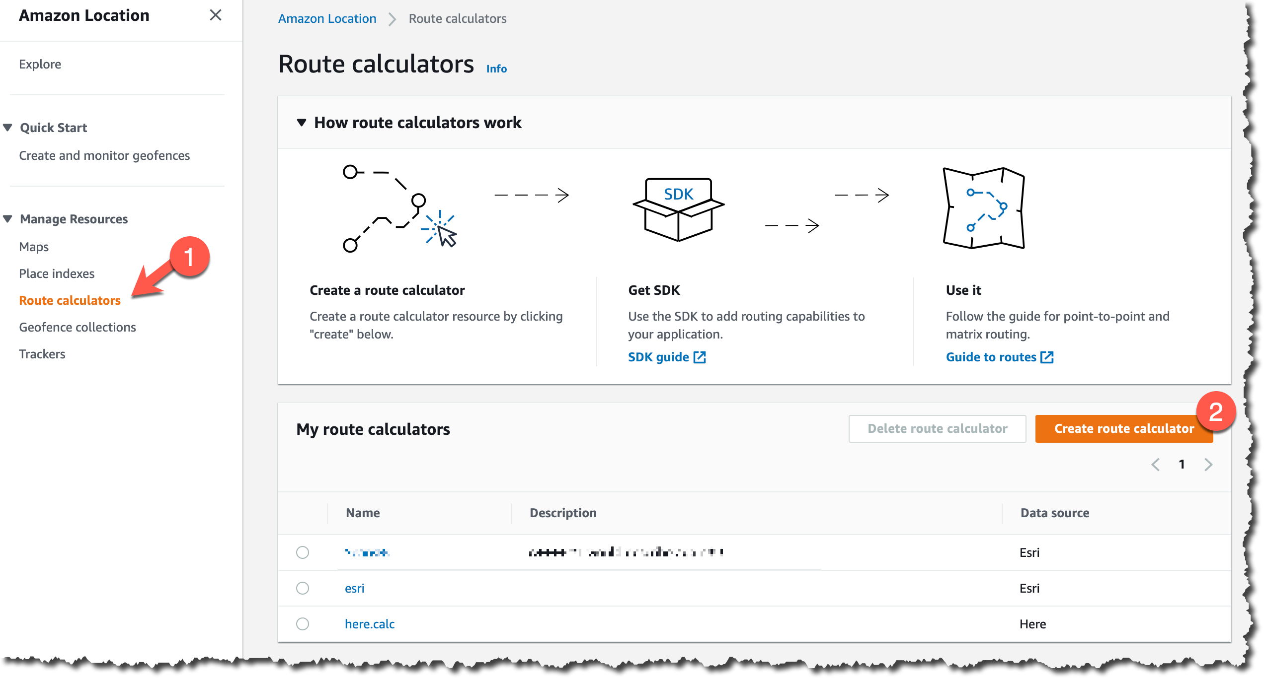
Post Syndicated from Pauline Kelly original https://aws.amazon.com/blogs/messaging-and-targeting/getting-started-with-push-notifications-using-aws-amplify/

This article was written by Pauline Kelly and Rob Costello, Public Sector Solutions Architects, AWS.

The code in this blog will run on OSX 10.11.6 (El Capitan) and higher, and XCode 8.1 and higher.

Push notifications are a key capability provided by mobile apps to engage with users, providing real-time updates or new information. However, they require integration of several components provided by different vendors. This can be difficult for new mobile developers, or developers who are new to Amazon Web Services (AWS).

As a mobile app developer, building high-quality apps that people want to use requires focus on the front-end components. Still, backend services also need to be considered to help ensure the app provides the level of scalability, reliability, and security that is expected of modern mobile applications. In this post, we will provide an example of how to implement Push Notifications in your mobile apps using AWS Amplify and Amazon Pinpoint, using React Native code to help get you started.

Usage Patterns

There are several use cases where developers benefit from adding Push Notifications into their mobile app, including:

  • Asynchronous actions, such as when an order is placed through an app, and confirmation or status notifications are sent to the user.
  • Scheduled reminders, to provide time-bound notifications to users to prompt engagement, such as “It’s been 7 days since you last checked in, would you like to check in now?”.
  • Instant messaging, where your app provides two-way communication (i.e., chat). This ensures your users can engage with each other in near real-time.

Component Definitions

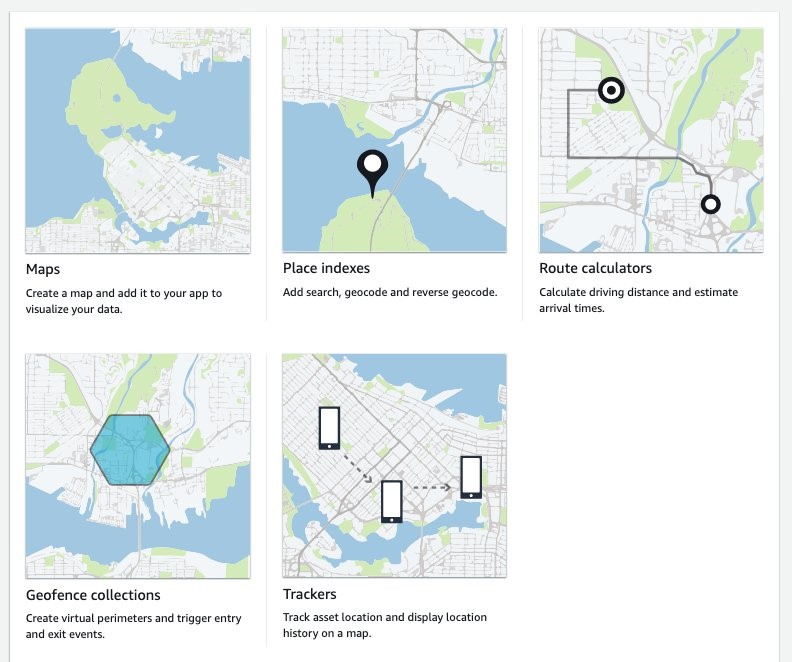
The components necessary to add push notifications to your app are:

Platform – These are the services provided by mobile device builders (e.g. Apple, Google, Amazon), that transport the messages to the end devices. The Platforms offer device registration, app token creation and management, and the delivery channel for notifications to be delivered to devices. There are several different services that you can use to send push notifications to the users of your applications. The platform you use largely depends on which app store your customers use to obtain your app. The most common platforms are Apple Push Notification service (APNs), Firebase Cloud Messaging (FCM), Baidu Cloud Push, and Amazon Device Messaging (ADM).

Provider – The Provider allows app registration and messaging to be coordinated by your mobile apps backend system, to allow for event or schedule based interactions from your backend with your mobile app. In AWS, we provide both Amazon Simple Notification Service (SNS) and Amazon Pinpoint to fill the role of the Provider.

Client – The client is your mobile application, running on a physical device. On initial launch of the application, two persistent and secure channels are established. First is between the Platform and the Client, which results in the creation of a globally-unique, app-specific device token. Next, the other sets up push notifications between the Provider and the Platform, using the device token. The device token is used to identify the destination for the notifications.

client, platform and provider components with no connections

AWS Options

AWS provides two services that can be used for provide Push Notification services for your mobile apps.

Amazon Pinpoint – Pinpoint enables marketers and developers to deliver customer-centric engagement experiences. It provides a collection of capabilities that enable collection of data from audiences, real-time and historic analytics, and execution of campaigns for direct customer engagement over multiple channels, such as email, SMS, or push notifications. Pinpoint makes it easy to manage device registration, integration with notification channel systems, and integration with other AWS services to create a fully-featured mobile application backend. AWS Amplify includes support for deploying and configuring Pinpoint projects to use in your mobile application.

Amazon Simple Notification Service (SNS) – SNS, or Simple Notification Service, is a publish-subscribe service that accepts incoming messages and delivers them to a variety of destinations, such as using push notifications to mobile devices. Messages are sent from a Publisher (your mobile app backend) to a Subscription, in the form of a Topic. Subscriptions are linked to one or more Platform Applications, which is the Platform you want to connect to (such as APNs or FCM). Each Platform Application has individual Endpoints which are created using the SNS SDK on the device, and passing in the unique device token. To explore fanout patterns with SNS, refer to this blog post.

While both SNS and Pinpoint have Push Notifications capability, Amazon Pinpoint provides a simpler development experience when leveraging AWS Amplify, and a more robust management and operational capability for app owners and developers. The rest of this post will focus on the use of Pinpoint and Amplify.

Registration and Data-flows

In this post we will use the APNs (Apple Push Notification Service) platform for push notifications, but a similar pattern is used for other platforms. The following events take place when a push notification is triggered:

  1. A Device establishes a TLS connection with APNs based on a pre-existing device-specific certificate, and requests an app-specific token to use for push notifications.
  2. The Device passes the token to the AWS provider to register for notifications.
  3. Based on some form of event or trigger, such as a marketer launching a new campaign, a notification can be generated programmatically and sent to the AWS provider (Pinpoint or SNS).
  4. The AWS provider delivers the notification to APNs, along with the associated device token(s) to deliver it.
  5. APNs pushes the notification to the device(s).

client, platform and provider components with connections

For details of how the APNs platform works, please consult the relevant services documentation at https://developer.apple.com/library/archive/documentation/NetworkingInternet/Conceptual/RemoteNotificationsPG/APNSOverview.html.

Setting up APNs prerequisites

Note: You will need an account with the Apple Developer Program, as an individual or as part of an organization, and you must have agent or admin privileges in that account. Also, Push Notifications in the Apple ecosystem require a physical device, the iOS simulator is not capable of receiving push notifications.

To setup the required APNs components, follow the Amplify guide to create:

  • An app ID.
  • An SSL certificate, which authorizes you to send push notifications to your app through APNs.
  • A registration for your test device, such as an iPhone, with your Apple Developer account.
  • An iOS distribution certificate, which enables you to install your app on your test device.
  • A provisioning profile, which allows your app to run on your test device.

Setting up your development workstation

Note: As this post focuses on using APNs for an iOS device, you must perform the following steps on an Apple device.

On your development workstation, install all React Native CLI prerequisites identified at https://reactnative.dev/docs/environment-setup, including:

  • NodeJS: JavaScript runtime, used to run your application
  • Watchman: watches files and records when they change, used to update your React Native app automatically rather than manually triggering a rebuild while developing
  • Xcode: integrated development environment for creating iOS applications and more, installed on macOS
  • CocoaPods: a dependency manager for Swift and Objective-C Cocoa projects

You will need to set up the Amplify CLI, which is used to configure the application with Amplify. Be sure to configure the Amplify CLI with credentials and other settings following the documentation here before proceeding.

Set up a new React Native App

Create a new React Native App to begin:

npx react-native init MyApp —template react-native-template-typescript
cd MyApp

Firstly, use the Amplify CLI to initialize the new app:

amplify init
Scanning for plugins...
Plugin scan successful
Note: It is recommended to run this command from the root of your app directory
? Enter a name for the project MyApp
? Enter a name for the environment dev
? Choose your default editor: Visual Studio Code
? Choose the type of app that you're building javascript
Please tell us about your project
? What javascript framework are you using react-native
? Source Directory Path:  src
? Distribution Directory Path: /
? Build Command:  npm run-script build
? Start Command: npm run-script start
Using default provider  awscloudformation

For more information on AWS Profiles, see:
https://docs.aws.amazon.com/cli/latest/userguide/cli-configure-profiles.html

? Do you want to use an AWS profile? Yes
? Please choose the profile you want to use default

Then install the required React and CocoaPod dependencies:

npm install aws-amplify-react-native aws-amplify @aws-amplify/pushnotification @react-native-community/push-notification-ios @react-native-community/netinfo
npx pod-install

We are now going to add authentication for the user to sign into the app, and send/receive push notifications. Adding authentication with the default configuration creates a Cognito User Pool in the cloud, and allows Amplify applications to use the identity of the authenticated user.

Note that authentication with Cognito User Pools is not strictly required for Amazon Pinpoint Push Notifications to function, you can use Cognito Identity Pools for unauthenticated integration with Pinpoint APIs in your mobile app.

amplify add auth
Do you want to use the default authentication and security configuration? Default configuration
Warning: you will not be able to edit these selections. 
How do you want users to be able to sign in? Username
Do you want to configure advanced settings? No, I am done.

To finish the creation of the Amazon Cognito User Pool, push the changes to AWS:

amplify push
? Are you sure you want to continue? (Y/n)

The Amplify Analytics module is required before Push Notifications can be configured. The Analytics module creates and configures the Amazon Pinpoint endpoint required for the PushNotification library to be able to register for and be a target for notifications.

amplify add analytics
? Select an Analytics provider Amazon Pinpoint
? Provide your Pinpoint resource name: MyAppAnalytics
? Apps need authorization to send analytics events. Do you want to allow guests and unauthenticated users to send analytics events? (we recommend you allow this when getting started) (Y/n) Yes

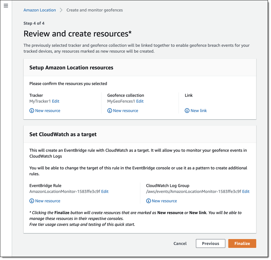
To finish the creation of the Amazon Pinpoint endpoint by Amplify CLI, push the changes to AWS. Here is a list of the cloud resources that will be created when you push the stack to cloud:

  • Amazon Cognito User Pool
  • Amazon Cognito Federated Identity Pool
  • Amazon Pinpoint Project (linked to User Pool)
  • Associated AWS IAM Roles

For specific details, you can look in the “amplify” directory in your project for the AWS CloudFormation templates created by the cli.

amplify push
? Are you sure you want to continue? (Y/n)

Next, use the Amplify CLI to add notifications to the project. During the setup for notifications, Amplify will ask you for the path to your *.p12 certificate, which is generated in XCode using your Apple Developer Account. Please refer to the instructions here:

Amplify Notifications: https://docs.amplify.aws/lib/push-notifications/getting-started/q/platform/js#setup-for-ios
Pinpoint Push Notification Setup: https://docs.aws.amazon.com/pinpoint/latest/developerguide/apns-setup.html

amplify add notifications
? Choose the push notification channel to enable. APNS
? Provide your Pinpoint resource name: <Choose default or provide a name>
? Choose authentication method used for APNs Certificate
? The certificate file path (.p12): <path to APNs p12 certificate>
? The certificate password (if any):
MAC verified OK
✔ The APNS channel has been successfully enabled.

Note that when the Notifications category is added, Amplify CLI also adds the Auth category, which creates and configures an Amazon Cognito User to allow authenticated access to the Amazon Pinpoint endpoint.

Next, you will need to open the iOS workspace of the application in XCode, found in ios/MyApp.xcworkspace. To enable notifications to function on iOS, the following settings for the project should be changed using Xcode to enable the @react-native-community/push-notifications-ios module to function:

  1. Add the Background Mode – Remote Notifications capability – https://github.com/react-native-push-notification-ios/push-notification-ios#add-capabilities–background-mode—remote-notifications
  2. Add support for the notification and register events that will be used – https://github.com/react-native-push-notification-ios/push-notification-ios#augment-appdelegate

Finally, update the Apps Workspace settings in Xcode by setting the Bundler Identifier you created when configuring your Apple Developer account. Once your Team is specified in Xcode, it will now populate the associated Signing Certificate field.

xcode project view signing tab

Next you can configure your React Native app to send and receive Push Notifications.

Register and Receive Notifications

To register a device with Amazon Pinpoint to receive Push Notifications, the required libraries should be imported:

import Amplify from 'aws-amplify';
import awsconfig from './aws-exports';
import {withAuthenticator} from 'aws-amplify-react-native';
import Analytics from '@aws-amplify/analytics';
import PushNotification from '@aws-amplify/pushnotification';
import Auth from '@aws-amplify/auth';

Note that Pinpoint requires the Analytics category of Amplify to be configured and imported into your app.

With the required libraries loaded, the Amplify components should be configured with the AWS details created by the amplify push command that are stored in the aws-exports.js file.

Amplify.configure(awsconfig);
Auth.configure(awsconfig);
Analytics.configure(awsconfig);
PushNotification.configure(awsconfig);

Next, register functions to be called when the device registers with APNs, and when a notification is received.

The onRegister event will be triggered when iOS registers a new token with the APNs service, allowing the app to retrieve the token and register it with Amazon Pinpoint via the Analytics.updateEndpoint function. Take care to update the userId key in the Analytics configuration.

PushNotification.onRegister((token: any) => {
  _token = token;
  Analytics.updateEndpoint({
    address: token,
    optOut: 'NONE',
    userId: '<userId>',
  })
    .then((data) => {
      console.log('endpoint updated', JSON.stringify(data));
    })
    .catch((error) => {
      console.log('error updating endpoint', error);
    });
});

The onNotification event will be triggered when the open app receives a notification from Amazon Pinpoint via APNs. Here we can execute actions based on the notification if required:

PushNotification.onNotification((notification: any) => {
  // display notification in debug log in XCode
  console.log('in app notification received', notification);
});

If the app is not open when the notification is received, and the user clicks the notification prompt, the onNotificationOpened event will be triggered allow actions to also be executed.

PushNotification.onNotificationOpened((notification: any) => {
  // display notification in debug log in XCode
  console.log('the notification is opened from iOS', notification);
});

Finally, we must prompt the user to allow Push Notifications from the app:

PushNotification.requestIOSPermissions();

Send Push Notifications

To send Push Notifications, we can use the Amazon Pinpoint SDK. Push notifications are ordinarily sent from a back-end process or application, however you can send notifications from anywhere the Amazon Pinpoint SDK is used.

Code examples in Javascript and Python for using the SendMessage API are available in the Amazon Pinpoint documentation. These examples can be executed from a backend server process or via AWS Lambda.

The address token value used in these examples must match that of the target device token assigned by APNs. This will be visible in the console output of the mobile app when the onRegister event is triggered.

The IAM Role used by your backend server process or AWS Lambda must have the following permission policy applied:

{
    "Effect": "Allow",
    "Action": "mobiletargeting:SendMessages", 
    "Resource": "arn:aws:mobiletargeting:<region>:<accountID>:apps/<projectID>/*"
}

Testing Push Notifications

Now run the project locally:

npx react-native run-ios

This will start Metro for React Native in a new Terminal window. Metro is a bundler for React Native which transpiles JavaScript into native code for use on client devices.

command line running metro bundler

You should now be able to connect your test device to your development workstation, change the target device and run the application from Xcode (Push Notifications are not available in the iOS Simulator in XCode).

You can now test sending and receiving notifications.

Adding Pinpoint Features

Now that you have a functioning mobile app able to receive Push Notifications, Amazon Pinpoint can be used by app owners to engage users through customised Campaigns or Journeys. A campaign sends tailored messages on a schedule that you define. With Journeys, you can send messages to your customers based on their attributes, behaviours, and activities.

Thanks to AWS Amplify, the application has already deployed an Amazon Pinpoint Project for you, so your next steps for engaging users will be:

  1. Creating a Segment of your users that you would like to target.
  2. Create a Campaign or Journey to start communicating with your Segment using Push Notifications.

Amazon Pinpoint can be combined with other AWS services for more advanced scenarios, such as Predictive User Engagement. An example solution that integrates Amazon Personalize created by the AWS Solutions team can be found at to https://aws.amazon.com/solutions/implementations/predictive-user-engagement/

Cleanup

To clean up the project use:

amplify delete

to delete the resources created by the Amplify CLI.

Conclusion

This post has explored how Amazon Pinpoint and the Amplify Framework can be used more easily add Push Notifications into your mobile apps. Using the example provided, you can quickly get started with integrating the required components and configuring your AWS account, so you can run campaigns to engage with your users.

Feedback

We hope you like the Push Notification features in Amazon Pinpoint and the Amplify Framework! Let us know how we are doing, and submit any feedback in the Amplify JavaScript GitHub repository. You can read more about this feature on the Amplify Framework website. Also, check out our community site to find the events, posts, and contributors to the Amplify community.


Amazon Location Service Is Now Generally Available with New Routing and Satellite Imagery Capabilities

Post Syndicated from Marcia Villalba original https://aws.amazon.com/blogs/aws/amazon-location-service-is-now-generally-available-with-new-routing-and-satellite-imagery-capabilities/

In December of 2020, we made Amazon Location Service available in preview form for you to start building web and mobile applications with location-based features. Today I’m pleased to announce that we are making Amazon Location generally available along with two new features: routing and satellite imagery.

I have been a full-stack developer for over 15 years. On multiple occasions, I was tasked with creating location-based applications. The biggest challenges I faced when I worked with location providers were integrating the applications into the existing application backend and frontend and keeping the data shared with the location provider secure. When Amazon Location was made available in preview last year, I was so excited. This service makes it possible to build location-based applications with a native integration with AWS services. It uses trusted location providers like Esri and HERE and customers remain in control of their data.

Amazon Location includes the following features:

  • Maps to visualize location information.
  • Places to enable your application to offer point-of-interest search functionality, convert addresses into geographic coordinates in latitude and longitude (geocoding), and convert a coordinate into a street address (reverse geocoding).
  • Routes to use driving distance, directions, and estimated arrival time in your application.
  • Trackers to allow you to retrieve the current and historical location of the devices running your tracking-enabled application.
  • Geofences to give your application the ability to detect and act when a tracked device enters or exits a geographical boundary you define as a geofence. When a breach of the geofence is detected, Amazon Location will send an event to Amazon EventBridge, which can trigger a downstream set of actions, like invoking an AWS Lambda function or sending a notification using Amazon Simple Notification Service (SNS). This level of integration with AWS services is one of the most powerful features of Amazon Location. It will help shorten your application’s time to production.

In the preview announcement blog post, Jeff introduced the service functionality in a lot of detail. In this blog post, I want to focus on the new two features: satellite imagery and routing.

Satellite Imagery

You can use satellite imagery to pack your maps with information and provide more context to the map users. It helps the map users answer questions like “Is there a swamp in that area?” or “What does that building look like?”

To get started with satellite imagery maps, go to the Amazon Location console. On Create a new map, choose Esri Imagery. 

Creating a new map with satellite imagery

Routing
With Amazon Location Routes, your application can request the travel time, distance, and all directions between two locations. This makes it possible for your application users to obtain accurate travel-time estimates based on live road and traffic information.

If you provide these extra attributes when you use the route feature, you can get very tailored information including:

  • Waypoints: You can provide a list of ordered intermediate positions to be reached on the route. You can have up to 25 stopover points including the departure and destination.
  • Departure time: When you specify the departure time for this route, you will receive a result optimized for the traffic conditions at that time.
  • Travel mode: The mode of travel you specify affects the speed and the road compatibility. Not all vehicles can travel on all roads. The available travel modes are car, truck and walking. Depending on which travel mode you select, there are parameters that you can tune. For example, for car and truck, you can specify if you want a route without ferries or tolls. But the most interesting results are when you choose the truck travel mode. You can define the truck dimensions and weight and then get a route that is optimized for these parameters. No more trucks stuck under bridges!

Amazon Location Service and its features can be used for interesting use cases with low effort. For example, delivery companies using Amazon Location can optimize the order of the deliveries, monitor the position of the delivery vehicles, and inform the customers when the vehicle is arriving. Amazon Location can be also used to route medical vehicles to optimize the routing of patients or medical supplies. Logistic companies can use the service to optimize their supply chain by monitoring all the delivery vehicles.

To use the route feature, start by creating a route calculator. In the Amazon Location console, choose Route calculators. For the provider of the route information, choose Esri or HERE.

Screenshot of create a new routing calculator

You can use the route calculator from the AWS SDKs, AWS Command Line Interface (CLI) or the Amazon Location HTTP API.

For example, to calculate a simple route between departure and destination positions using the CLI, you can write something like this:

aws location \
    calculate-route \
        --calculator-name MyExampleCalculator \
        --departure-position -123.1376951951309 49.234371474778385 \
        --destination-position -122.83301379875074 49.235860182576886

The departure-position and destination-positions are defined as longitude, latitude.

This calculation returns a lot of information. Because you didn’t define the travel mode, the service assumes that you are using a car. You can see the total distance of the route (in this case, 29 kilometers). You can change the distance unit when you do the calculation. The service also returns the duration of the trip (in this case, 29 minutes). Because you didn’t define when to depart, Amazon Location will assume that you want to travel when there is the least amount of traffic.

{
    "Legs": [{
        "Distance": 26.549,
        "DurationSeconds": 1711,
        "StartPosition":[-123.1377012, 49.2342994],
        "EndPosition": [-122.833014,49.23592],
        "Steps": [{
            "Distance":0.7,
            "DurationSeconds":52,
            "EndPosition":[-123.1281,49.23395],
            "GeometryOffset":0,
            "StartPosition":[-123.137701,49.234299]},
            ...
        ]
    }],
    "Summary": {
        "DataSource": "Esri",
        "Distance": 29.915115551209176,
        "DistanceUnit": "Kilometers",
        "DurationSeconds": 2275.5813682980006,
        "RouteBBox": [
            -123.13769762299995,
            49.23068000000006,
            -122.83301399999999,
            49.258440000000064
        ]
    }
}

It will return an array of steps, which form the directions to get from departure to destination. The steps are represented by a starting position and end position. In this example, there are 11 steps and the travel mode is a car.

Screenshot of route drawn in map

The result changes depending on the travel mode you selected. For example, if you do the calculation for the same departure and destination positions but choose a travel mode of walking, you will get a series of steps that draw the map as shown below. The travel time and distance are different: 24.1 kilometers and 6 hours and 43 minutes.

Map of route when walking

Available Now
Amazon Location Service is now available in the US East (N. Virginia), US East (Ohio), US West (Oregon), Europe (Frankfurt), Europe (Ireland), Europe (Stockholm), Asia Pacific (Singapore), Asia Pacific (Sydney), and Asia Pacific (Tokyo) Regions.

Learn about the pricing models of Amazon Location Service. For more about the service, see Amazon Location Service

Marcia

Amplify Flutter is Now Generally Available: Build Beautiful Cross-Platform Apps

Post Syndicated from Martin Beeby original https://aws.amazon.com/blogs/aws/amplify-flutter-is-now-generally-available-build-beautiful-cross-platform-apps/

AWS Amplify is a set of tools and services for building secure, scalable mobile and web applications. Currently, Amplify supports iOS, Android, and JavaScript (web and React Native) and is the quickest and easiest way to build applications powered by Amazon Web Services (AWS).

Flutter is Google’s UI toolkit for building natively compiled mobile, web, and desktop applications from a single code base and is one of the fastest-growing mobile frameworks.

Amplify Flutter brings together AWS Amplify and Flutter, and we designed it for customers who have invested in the Flutter ecosystem and now want to take advantage of the power of AWS.

In August 2020, we launched the developer preview of Amplify Flutter and asked for feedback. We were delighted with the response. After months of refining the service, today we are happy to announce the general availability of Amplify Flutter.

New Amplify Flutter Features in GA
The GA release makes it easier to build powerful Flutter apps with the addition of three new capabilities:

First, we recently added a GraphQL API backed by AWS AppSync as well as REST APIs and handlers using Amazon API Gateway and AWS Lambda.

Second, Amplify DataStore provides a programming model for leveraging shared and distributed data without writing additional code for offline and online scenarios, which makes working with distributed, cross-user data just as simple as working with local-only data.

Finally, we have Hosted UI which is a great way to implement authentication, and works with Amazon Cognito and other social identity providers such as Facebook, Google and Amazon. Hosted UI is a customizable OAuth 2.0 flow that allows you to launch a login screen without embedding the SDK for Cognito or a social provider in your application.

Digging Deeper Into Amplify DataStore
I have been building an app over the past two weeks using Amplify Flutter, and my favorite feature is Amplify DataStore, primarily because it has saved me so much time.

Working with the REST and GraphQL APIs is great in Amplify. However, when I create a mobile app, I’m often thinking about what happens when the mobile device has intermittent connectivity and can’t connect to the API endpoints. Storing data locally and syncing back to the cloud can become quite complicated. Amplify DataStore solves that problem by providing a persistent on-device data store that handles the offline or online scenario.

When I started developing my app, I used DataStore as a stand-alone local database. However, its power became apparent to me when I connected it to a cloud backend. DataStore uses my AWS AppSync API to sync data when network connectivity is available. If the app is offline, it stores it locally, ready for when a connection becomes available.

Amplify DataStore automatically versions data and implements conflict detection and resolution in the cloud using AppSync. The toolchain also generates object definitions for Dart based on the GraphQL schema that I provide.

Writing to Amplify DataStore
Writing to the DataStore is straightforward. The documentation site shows an example that you can try yourself that uses a schema from a blog site.

Post newPost = Post(
    title: 'New Post being saved', rating: 15, status: PostStatus.DRAFT);
await Amplify.DataStore.save(newPost);

Reading from Amplify DataStore
To read from the DataStore, you can query for all records of a given model type.

try {
   List<Post> posts = await Amplify.DataStore.query(Post.classType);
 } catch (e) {
   print("Query failed: " + e);
 }

Synchronization with Amplify DataStore
If you enable data synchronization, there can be different versions of an object across clients, and multiple clients may have updated their copies of an object. DataStore will converge different object versions by applying conflict detection and resolution strategies. The default resolution is called Auto Merge, but other strategies include optimistic concurrency control and custom Lambda functions.

Additional Amplify Flutter Features
Amplify Flutter allows you to work with AWS in three additional ways:

  • Authentication. Amplify Flutter provides an interface for authenticating a user and enables use cases like Sign-Up, Sign-In, and Multi-Factor Authentication. Behind the scenes, it provides the necessary authorization to the other Amplify categories. It comes with built-in support for Cognito user pools and identity pools.
  • Storage. Amplify Flutter provides an interface for managing user content for your app in public, protected, or private storage buckets. It enables use cases like upload, download, and deleting objects and provides built-in support for Amazon Simple Storage Service (S3) by default.
  • Analytics. Amplify Flutter enables you to collect tracking data for authenticated or unauthenticated users in Amazon Pinpoint. You can easily record events and extend the default functionality for custom metrics or attributes as needed.

Available Now
Amplify Flutter is now available in GA in all regions that support AWS Amplify. There is no additional cost for using Amplify Flutter; you only pay for the backend services your applications use above the free tier; check out the pricing page for more details.

Visit the Amplify Flutter documentation to get started and learn more. Happy coding.

— Martin

Amazon Location – Add Maps and Location Awareness to Your Applications

Post Syndicated from Jeff Barr original https://aws.amazon.com/blogs/aws/amazon-location-add-maps-and-location-awareness-to-your-applications/

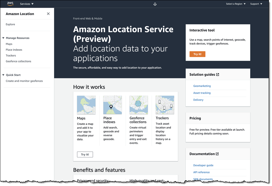
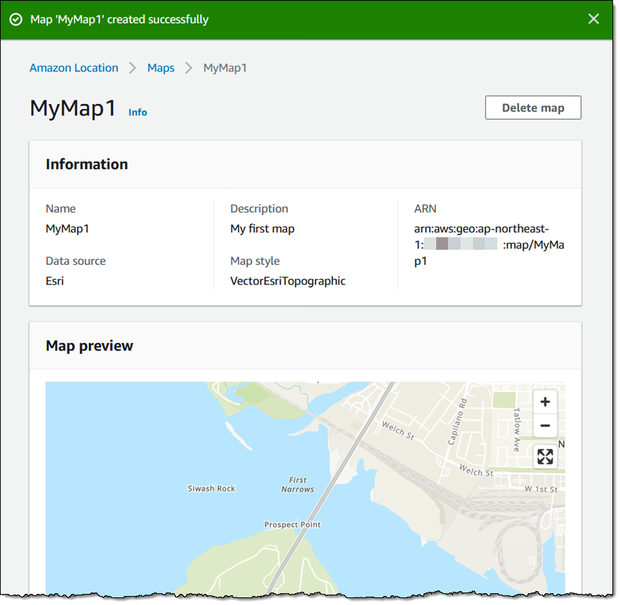
We want to make it easier and more cost-effective for you to add maps, location awareness, and other location-based features to your web and mobile applications. Until now, doing this has been somewhat complex and expensive, and also tied you to the business and programming models of a single provider.

Introducing Amazon Location Service
Today we are making Amazon Location available in preview form and you can start using it today. Priced at a fraction of common alternatives, Amazon Location Service gives you access to maps and location-based services from multiple providers on an economical, pay-as-you-go basis.

You can use Amazon Location Service to build applications that know where they are and respond accordingly. You can display maps, validate addresses, perform geocoding (turn an address into a location), track the movement of packages and devices, and much more. You can easily set up geofences and receive notifications when tracked items enter or leave a geofenced area. You can even overlay your own data on the map while retaining full control.

You can access Amazon Location Service from the AWS Management Console, AWS Command Line Interface (CLI), or via a set of APIs. You can also use existing map libraries such as Mapbox GL and Tangram.

All About Amazon Location
Let’s take a look at the types of resources that Amazon Location Service makes available to you, and then talk about how you can use them in your applications.

MapsAmazon Location Service lets you create maps that make use of data from our partners. You can choose between maps and map styles provided by Esri and by HERE Technologies, with the potential for more maps & more styles from these and other partners in the future. After you create a map, you can retrieve a tile (at one of up to 16 zoom levels) using the GetMapTile function. You won’t do this directly, but will use Mapbox GL, Tangram, or another library instead.

Place Indexes – You can choose between indexes provided by Esri and HERE. The indexes support the SearchPlaceIndexForPosition function which returns places, such as residential addresses or points of interest (often known as POI) that are closest to the position that you supply, while also performing reverse geocoding to turn the position (a pair of coordinates) into a legible address. Indexes also support the SearchPlaceIndexForText function, which searches for addresses, businesses, and points of interest using free-form text such as an address, a name, a city, or a region.

Trackers –Trackers receive location updates from one or more devices via the BatchUpdateDevicePosition function, and can be queried for the current position (GetDevicePosition) or location history (GetDevicePositionHistory) of a device. Trackers can also be linked to Geofence Collections to implement monitoring of devices as they move in and out of geofences.

Geofence Collections – Each collection contains a list of geofences that define geographic boundaries. Here’s a geofence (created with geojson.io) that outlines a park near me:

Amazon Location in Action
I can use the AWS Management Console to get started with Amazon Location and then move on to the AWS Command Line Interface (CLI) or the APIs if necessary. I open the Amazon Location Service Console, and I can either click Try it! to create a set of starter resources, or I can open up the navigation on the left and create them one-by-one. I’ll go for one-by-one, and click Maps:

Then I click Create map to proceed:

I enter a Name and a Description:

Then I choose the desired map and click Create map:

The map is created and ready to be added to my application right away:

Now I am ready to embed the map in my application, and I have several options including the Amplify JavaScript SDK, the Amplify Android SDK, the Amplify iOS SDK, Tangram, and Mapbox GL (read the Developer Guide to learn more about each option).

Next, I want to track the position of devices so that I can be notified when they enter or exit a given region. I use a GeoJSON editing tool such as geojson.io to create a geofence that is built from polygons, and save (download) the resulting file:

I click Create geofence collection in the left-side navigation, and in Step 1, I add my GeoJSON file, enter a Name and Description, and click Next:

Now I enter a Name and a Description for my tracker, and click Next. It will be linked to the geofence collection that I just created:

The next step is to arrange for the tracker to send events to Amazon EventBridge so that I can monitor them in CloudWatch Logs. I leave the settings as-is, and click Next to proceed:

I review all of my choices, and click Finalize to move ahead:

The resources are created, set up, and ready to go:

I can then write code or use the CLI to update the positions of my devices:

$ aws location batch-update-device-position \
   --tracker-name MyTracker1 \
   --updates "DeviceId=Jeff1,Position=-122.33805,47.62748,SampleTime=2020-11-05T02:59:07+0000"

After I do this a time or two, I can retrieve the position history for the device:

$ aws location get-device-position-history \
  -tracker-name MyTracker1 --device-id Jeff1
------------------------------------------------
|           GetDevicePositionHistory           |
+----------------------------------------------+
||               DevicePositions              ||
|+---------------+----------------------------+|
||  DeviceId     |  Jeff1                     ||
||  ReceivedTime |  2020-11-05T02:59:17.246Z  ||
||  SampleTime   |  2020-11-05T02:59:07Z      ||
|+---------------+----------------------------+|
|||                 Position                 |||
||+------------------------------------------+||
|||  -122.33805                              |||
|||  47.62748                                |||
||+------------------------------------------+||
||               DevicePositions              ||
|+---------------+----------------------------+|
||  DeviceId     |  Jeff1                     ||
||  ReceivedTime |  2020-11-05T03:02:08.002Z  ||
||  SampleTime   |  2020-11-05T03:01:29Z      ||
|+---------------+----------------------------+|
|||                 Position                 |||
||+------------------------------------------+||
|||  -122.43805                              |||
|||  47.52748                                |||
||+------------------------------------------+||

I can write Amazon EventBridge rules that watch for the events, and use them to perform any desired processing. Events are published when a device enters or leaves a geofenced area, and look like this:

{
  "version": "0",
  "id": "7cb6afa8-cbf0-e1d9-e585-fd5169025ee0",
  "detail-type": "Location Geofence Event",
  "source": "aws.geo",
  "account": "123456789012",
  "time": "2020-11-05T02:59:17.246Z",
  "region": "us-east-1",
  "resources": [
    "arn:aws:geo:us-east-1:123456789012:geofence-collection/MyGeoFences1",
    "arn:aws:geo:us-east-1:123456789012:tracker/MyTracker1"
  ],
  "detail": {
        "EventType": "ENTER",
        "GeofenceId": "LakeUnionPark",
        "DeviceId": "Jeff1",
        "SampleTime": "2020-11-05T02:59:07Z",
        "Position": [-122.33805, 47.52748]
  }
}

Finally, I can create and use place indexes so that I can work with geographical objects. I’ll use the CLI for a change of pace. I create the index:

$ aws location create-place-index \
  --index-name MyIndex1 --data-source Here

Then I query it to find the addresses and points of interest near the location:

$ aws location search-place-index-for-position --index-name MyIndex1 \
  --position "[-122.33805,47.62748]" --output json \
  |  jq .Results[].Place.Label
"Terry Ave N, Seattle, WA 98109, United States"
"900 Westlake Ave N, Seattle, WA 98109-3523, United States"
"851 Terry Ave N, Seattle, WA 98109-4348, United States"
"860 Terry Ave N, Seattle, WA 98109-4330, United States"
"Seattle Fireboat Duwamish, 860 Terry Ave N, Seattle, WA 98109-4330, United States"
"824 Terry Ave N, Seattle, WA 98109-4330, United States"
"9th Ave N, Seattle, WA 98109, United States"
...

I can also do a text-based search:

$ aws location search-place-index-for-text --index-name MyIndex1 \
  --text Coffee --bias-position "[-122.33805,47.62748]" \
  --output json | jq .Results[].Place.Label
"Mohai Cafe, 860 Terry Ave N, Seattle, WA 98109, United States"
"Starbucks, 1200 Westlake Ave N, Seattle, WA 98109, United States"
"Metropolitan Deli and Cafe, 903 Dexter Ave N, Seattle, WA 98109, United States"
"Top Pot Doughnuts, 590 Terry Ave N, Seattle, WA 98109, United States"
"Caffe Umbria, 1201 Westlake Ave N, Seattle, WA 98109, United States"
"Starbucks, 515 Westlake Ave N, Seattle, WA 98109, United States"
"Cafe 815 Mercer, 815 9th Ave N, Seattle, WA 98109, United States"
"Victrola Coffee Roasters, 500 Boren Ave N, Seattle, WA 98109, United States"
"Specialty's, 520 Terry Ave N, Seattle, WA 98109, United States"
...

Both of the searches have other options; read the Geocoding, Reverse Geocoding, and Search to learn more.

Things to Know
Amazon Location is launching today as a preview, and you can get started with it right away. During the preview we plan to add an API for routing, and will also do our best to respond to customer feedback and feature requests as they arrive.

Pricing is based on usage, with an initial evaluation period that lasts for three months and lets you make numerous calls to the Amazon Location APIs at no charge. After the evaluation period you pay the prices listed on the Amazon Location Pricing page.

Amazon Location is available in the US East (N. Virginia), US East (Ohio), US West (Oregon), Europe (Ireland), and Asia Pacific (Tokyo) Regions.

Jeff;


New AWS Amplify Admin UI Helps You Develop App Backends, No Cloud Experience Required

Post Syndicated from Marcia Villalba original https://aws.amazon.com/blogs/aws/aws-amplify-admin-ui-helps-you-develop-app-backends-no-cloud-experience-required/

Today AWS Amplify announces new Admin UI to configure an application backend, and manage app users and content outside the AWS console. This new feature makes it easier to use AWS services and accelerates the development and management of full-stack web and mobile apps.

We launched AWS Amplify in November 2018, and since then it has been helping front-end web and mobile developers to quickly develop and deploy cloud-connected web and mobile applications. In order to stay ahead of the curve and deliver innovation to customers, businesses need to ship features fast. However, developers and non-developers who are unfamiliar with AWS fundamentals require training, which slows the entire process down.

AWS Amplify today launches a new Admin UI that enables team members to interface with AWS without requiring an AWS account (only the first deployment requires an AWS account).

The Admin UI provides simple yet powerful tools to model database tables, add authentication and authorization, and manage app content, users, and groups. It also offers the ability to manage the application users and content. The AWS Amplify Admin UI focuses on data types rather than backend infrastructure. All the backend resources generate infrastructure as code (IaC) templates that can be committed in the team repository and integrated with AWS Amplify continuous deployment workflow to manage the different environments.

Let’s Look at an Example Using the New AWS Amplify Admin UI
Imagine that you are a front-end web developer creating a website for a local restaurant. The restaurant owner wants to have a website where they can show their daily menu, and wants a simple way to update the content of the page every day.

There are many ways to solve this problem. You can spin up a server and install a CMS for the restaurant owner to manage the menu. For this particular use case, having a server exclusively to do this is just over-provisioning resources. Or, you can create the CMS yourself using serverless tools; however, this adds a lot of complexity and extra time to the development cycle.

Another option is to use the new AWS Amplify Admin UI that allows you to take advantage of many AWS managed services to create the backend quickly and also provides the ability to manage the application users and content.

The first thing you need to do is to create a new AWS Amplify app backend in the AWS Console. AWS Amplify will create a backend environment called staging. When, your app backend is ready, open the new Admin UI. If you would like to get another developer working on this application who doesn’t have experience with AWS, nor access to the AWS account, now you can grant access to them so they can continue the work on the UI. But for now, let’s imagine that you are going to do all the development.

Screenshot of opening the admin ui

The Admin UI contains all the tools that application developers need to configure the application backend and that content managers need to update the application content.

In the sidebar of the Admin UI (as shown in the following illustration), you can find all the different options for setting up your application.

To get started with the restaurant website, you need a menu data model. For that, first go to Data (1), then create a new data model call Menu (2), add the necessary fields and Save and deploy (3) the model. Saving and deploying the model will create all the needed AWS resources in the backend, like an AWS AppSync API and a Amazon DynamoDB table to host the menu items. Deploying takes a few minutes.

Screenshot for data modeling

After your model is deployed, you can start working on your website. For this example I will be using React, one of the web frameworks supported by AWS Amplify, but you can do the same example with any of the supported frameworks.

First, you need to install the AWS Amplify CLI:

npm install -g @aws-amplify/cli

Then create a new React application:

npx create-react-app react-amplified
cd react-amplified

When your application is created, you can configure it with the AWS Amplify application we just created. For that, go back to the Admin UI and select Local setup instructions (1), and execute the amplify command (2) in the directory where the web application is stored in your computer.

Screenshot of pulling amplify configuration

When you execute that command, a browser window will open that asks you if you are sure that you want to log in to the AWS Amplify Admin UI. Selecting yes will grant the AWS Amplify CLI access to deploy updates to the backend directly from your local desktop. The CLI will prompt you with a few questions about your local environment, and finally will ask if you plan to modify this backend locally. Choose yes.

When that process ends, you will notice some changes in your web application directory: a couple of new directories were created (amplify and src/models) and also a new file (aws-exports.js). These files and directories hold all the configuration for your AWS Amplify application.

Now it’s time to develop your application. To access the menu data model you created in the first steps, you will use the DataStore library from AWS Amplify. DataStore allows you to connect to your deployed database and perform CRUD, sort and filter operations from your UI to manipulate backend data. In the Admin UI, you can see some examples on how to create, update, delete and query the model.

Screenshot of using the data model

When the website is ready, it’s time to add some content. The restaurant owner is the one adding the menu items. In order for them to be able to add items, they need to have permissions to access the Admin UI for this application.

To do this, you need to create a new Admin UI account for the restaurant owner with the correct permissions. Go to the AWS Amplify console for your application and then to the Admin UI management and invite users.

When adding new users to the Admin UI you can define their permission scope. If you want to grant them full access, they will be able to configure and manage the application backend environment, and if you want them just to be able to edit the content, you can give them the manage only access scope. For the restaurant owner grant manage only permissions.

Screenshot for inviting new users to the AdminUI

After sending the invite, the restaurant owner will receive an email with a link to access the Admin UI and a username and password to log in. When they log in, they can go to the Content tab (1) and start adding items in their menu (2) and they can see the items available in the table in the screen (3).

Screenshot adding new content

From this screen, the restaurant owner can add, delete and edit items in their menu whenever they want to. These changes are reflected in the website immediately after they save.

The use cases for Admin UI are endless, such as blogs, e-commerce sites, planning apps, etc. Developers can build complex and feature-rich apps by focusing on their domain-specific data model instead of spending hours deploying and stitching together cloud infrastructure. AWS Amplify gives front-end developers the fastest and easiest way to develop mobile and web apps. And all accessible to developers that are not familiar with the cloud and without the need to give AWS access to everybody in the team.

Availability
AWS Amplify Admin UI is available at launch in: US East (N. Virginia), US East (Ohio), US West (Oregon), Asia Pacific (Mumbai), Asia Pacific (Seoul), Asia Pacific (Singapore), Asia Pacific (Sydney), Asia Pacific (Tokyo), Canada (Central), Europe (Frankfurt), Europe (Ireland), and Europe (London).

For more information, visit the Amplify service page. Get started building a data model without an AWS account in the sandbox experience.

Marcia

Building Serverless Land: Part 2 – An auto-building static site

Post Syndicated from Benjamin Smith original https://aws.amazon.com/blogs/compute/building-serverless-land-part-2-an-auto-building-static-site/

In this two-part blog series, I show how serverlessland.com is built. This is a static website that brings together all the latest blogs, videos, and training for AWS serverless. It automatically aggregates content from a number of sources. The content exists in a static JSON file, which generates a new static site each time it is updated. The result is a low-maintenance, low-latency serverless website, with almost limitless scalability.

A companion blog post explains how to build an automated content aggregation workflow to create and update the site’s content. In this post, you learn how to build a static website with an automated deployment pipeline that re-builds on each GitHub commit. The site content is stored in JSON files in the same repository as the code base. The example code can be found in this GitHub repository.

The growing adoption of serverless technologies generates increasing amounts of helpful and insightful content from the developer community. This content can be difficult to discover. Serverless Land helps channel this into a single searchable location. By collating this into a static website, users can enjoy a browsing experience with fast page load speeds.

The serverless nature of the site means that developers don’t need to manage infrastructure or scalability. The use of AWS Amplify Console to automatically deploy directly from GitHub enables a regular release cadence with a fast transition from prototype to production.

Static websites

A static site is served to the user’s web browser exactly as stored. This contrasts to dynamic webpages, which are generated by a web application. Static websites often provide improved performance for end users and have fewer or no dependant systems, such as databases or application servers. They may also be more cost-effective and secure than dynamic websites by using cloud storage, instead of a hosted environment.

A static site generator is a tool that generates a static website from a website’s configuration and content. Content can come from a headless content management system, through a REST API, or from data referenced within the website’s file system. The output of a static site generator is a set of static files that form the website.

Serverless Land uses a static site generator for Vue.js called Nuxt.js. Each time content is updated, Nuxt.js regenerates the static site, building the HTML for each page route and storing it in a file.

The architecture

Serverless Land static website architecture

When the content.json file is committed to GitHub, a new build process is triggered in AWS Amplify Console.

Deploying AWS Amplify

AWS Amplify helps developers to build secure and scalable full stack cloud applications. AWS Amplify Console is a tool within Amplify that provides a user interface with a git-based workflow for hosting static sites. Deploy applications by connecting to an existing repository (GitHub, BitBucket Cloud, GitLab, and AWS CodeCommit) to set up a fully managed, nearly continuous deployment pipeline.

This means that any changes committed to the repository trigger the pipeline to build, test, and deploy the changes to the target environment. It also provides instant content delivery network (CDN) cache invalidation, atomic deploys, password protection, and redirects without the need to manage any servers.

Building the static website

  1. To get started, use the Nuxt.js scaffolding tool to deploy a boiler plate application. Make sure you have npx installed (npx is shipped by default with npm version 5.2.0 and above).
    $ npx create-nuxt-app content-aggregator

    The scaffolding tool asks some questions, answer as follows:Nuxt.js scaffolding tool inputs

  2. Navigate to the project directory and launch it with:
    $ cd content-aggregator
    $ npm run dev

    The application is now running on http://localhost:3000.The pages directory contains your application views and routes. Nuxt.js reads the .vue files inside this directory and automatically creates the router configuration.

  3. Create a new file in the /pages directory named blogs.vue:$ touch pages/blogs.vue
  4. Copy the contents of this file into pages/blogs.vue.
  5. Create a new file in /components directory named Post.vue :$ touch components/Post.vue
  6. Copy the contents of this file into components/Post.vue.
  7. Create a new file in /assets named content.json and copy the contents of this file into it.$ touch /assets/content.json

The blogs Vue component

The blogs page is a Vue component with some special attributes and functions added to make development of your application easier. The following code imports the content.json file into the variable blogPosts. This file stores the static website’s array of aggregated blog post content.

import blogPosts from '../assets/content.json'

An array named blogPosts is initialized:

data(){
    return{
      blogPosts: []
    }
  },

The array is then loaded with the contents of content.json.

 mounted(){
    this.blogPosts = blogPosts
  },

In the component template, the v-for directive renders a list of post items based on the blogPosts array. It requires a special syntax in the form of blog in blogPosts, where blogPosts is the source data array and blog is an alias for the array element being iterated on. The Post component is rendered for each iteration. Since components have isolated scopes of their own, a :post prop is used to pass the iterated data into the Post component:

<ul>
  <li v-for="blog in blogPosts" :key="blog">
     <Post :post="blog" />
  </li>
</ul>

The post data is then displayed by the following template in components/Post.vue.

<template>
    <div class="hello">
      <h3>{{ post.title }} </h3>
      <div class="img-holder">
          <img :src="post.image" />
      </div>
      <p>{{ post.intro }} </p>
      <p>Published on {{post.date}}, by {{ post.author }} p>
      <a :href="post.link"> Read article</a>
    </div>
</template>

This forms the framework for the static website. The /blogs page displays content from /assets/content.json via the Post component. To view this, go to http://localhost:3000/blogs in your browser:

The /blogs page

Add a new item to the content.json file and rebuild the static website to display new posts on the blogs page. The previous content was generated using the aggregation workflow explained in this companion blog post.

Connect to Amplify Console

Clone the web application to a GitHub repository and connect it to Amplify Console to automate the rebuild and deployment process:

  1. Upload the code to a new GitHub repository named ‘content-aggregator’.
  2. In the AWS Management Console, go to the Amplify Console and choose Connect app.
  3. Choose GitHub then Continue.
  4. Authorize to your GitHub account, then in the Recently updated repositories drop-down select the ‘content-aggregator’ repository.
  5. In the Branch field, leave the default as master and choose Next.
  6. In the Build and test settings choose edit.
  7. Replace - npm run build with – npm run generate.
  8. Replace baseDirectory: / with baseDirectory: dist

    This runs the nuxt generate command each time an application build process is triggered. The nuxt.config.js file has a target property with the value of static set. This generates the web application into static files. Nuxt.js creates a dist directory with everything inside ready to be deployed on a static hosting service.
  9. Choose Save then Next.
  10. Review the Repository details and App settings are correct. Choose Save and deploy.

    Amplify Console deployment

Once the deployment process has completed and is verified, choose the URL generated by Amplify Console. Append /blogs to the URL, to see the static website blogs page.

Any edits pushed to the repository’s content.json file trigger a new deployment in Amplify Console that regenerates the static website. This companion blog post explains how to set up an automated content aggregator to add new items to the content.json file from an RSS feed.

Conclusion

This blog post shows how to create a static website with vue.js using the nuxt.js static site generator. The site’s content is generated from a single JSON file, stored in the site’s assets directory. It is automatically deployed and re-generated by Amplify Console each time a new commit is pushed to the GitHub repository. By automating updates to the content.json file you can create low-maintenance, low-latency static websites with almost limitless scalability.

This application framework is used together with this automated content aggregator to pull together articles for http://serverlessland.com. Serverless Land brings together all the latest blogs, videos, and training for AWS Serverless. Download the code from this GitHub repository to start building your own automated content aggregation platform.

Building Serverless Land: Part 1 – Automating content aggregation

Post Syndicated from Benjamin Smith original https://aws.amazon.com/blogs/compute/building-serverless-land-part-1-automating-content-aggregation/

In this two part blog series, I show how serverlessland.com is built. This is a static website that brings together all the latest blogs, videos, and training for AWS Serverless. It automatically aggregates content from a number of sources. The content exists in static JSON files, which generate a new site build each time they are updated. The result is a low-maintenance, low-latency serverless website, with almost limitless scalability.

This blog post explains how to automate the aggregation of content from multiple RSS feeds into a JSON file stored in GitHub. This workflow uses AWS Lambda and AWS Step Functions, triggered by Amazon EventBridge. The application can be downloaded and deployed from this GitHub repository.

The growing adoption of serverless technologies generates increasing amounts of helpful and insightful content from the developer community. This content can be difficult to discover. Serverless Land helps channel this into a single searchable location. By automating the collection of this content with scheduled serverless workflows, the process robustly scales to near infinite numbers. The Step Functions MAP state allows for dynamic parallel processing of multiple content sources, without the need to alter code. On-boarding a new content source is as fast and simple as making a single CLI command.

The architecture

Automating content aggregation with AWS Step Functions

The application consists of six Lambda functions orchestrated by a Step Functions workflow:

  1. The workflow is triggered every 2 hours by an EventBridge scheduler. The schedule event passes an RSS feed URL to the workflow.
  2. The first task invokes a Lambda function that runs an HTTP GET request to the RSS feed. It returns an array of recent blog URLs. The array of blog URLs is provided as the input to a MAP state. The MAP state type makes it possible to run a set of steps for each element of an input array in parallel. The number of items in the array can be different for each execution. This is referred to as dynamic parallelism.
  3. The next task invokes a Lambda function that uses the GitHub REST API to retrieve the static website’s JSON content file.
  4. The first Lambda function in the MAP state runs an HTTP GET request to the blog post URL provided in the payload. The URL is scraped for content and an object containing detailed metadata about the blog post is returned in the response.
  5. The blog post metadata is compared against the website’s JSON content file in GitHub.
  6. A CHOICE state determines if the blog post metadata has already been committed to the repository.
  7. If the blog post is new, it is added to an array of “content to commit”.
  8. As the workflow exits the MAP state, the results are passed to the final Lambda function. This uses a single git commit to add each blog post object to the website’s JSON content file in GitHub. This triggers an event that rebuilds the static site.

Using Secrets in AWS Lambda

Two of the Lambda functions require a GitHub personal access token to commit files to a repository. Sensitive credentials or secrets such as this should be stored separate to the function code. Use AWS Systems Manager Parameter Store to store the personal access token as an encrypted string. The AWS Serverless Application Model (AWS SAM) template grants each Lambda function permission to access and decrypt the string in order to use it.

  1. Follow these steps to create a personal access token that grants permission to update files to repositories in your GitHub account.
  2. Use the AWS Command Line Interface (AWS CLI) to create a new parameter named GitHubAPIKey:
aws ssm put-parameter \
--name /GitHubAPIKey \
--value ReplaceThisWithYourGitHubAPIKey \
--type SecureString

{
    "Version": 1,
    "Tier": "Standard"
}

Deploying the application

  1. Fork this GitHub repository to your GitHub Account.
  2. Clone the forked repository to your local machine and deploy the application using AWS SAM.
  3. In a terminal, enter:
    git clone https://github.com/aws-samples/content-aggregator-example
    sam deploy -g
  4. Enter the required parameters when prompted.

This deploys the application defined in the AWS SAM template file (template.yaml).

The business logic

Each Lambda function is written in Node.js and is stored inside a directory that contains the package dependencies in a `node_modules` folder. These are defined for each function by its relative package.json file. The function dependencies are bundled and deployed using the sam build && deploy -g command.

The GetRepoContents and WriteToGitHub Lambda functions use the octokit/rest.js library to communicate with GitHub. The library authenticates to GitHub by using the GitHub API key held in Parameter Store. The AWS SDK for Node.js is used to obtain the API key from Parameter Store. With a single synchronous call, it retrieves and decrypts the parameter value. This is then used to authenticate to GitHub.

const AWS = require('aws-sdk');
const SSM = new AWS.SSM();


//get Github API Key and Authenticate
    const singleParam = { Name: '/GitHubAPIKey ',WithDecryption: true };
    const GITHUB_ACCESS_TOKEN = await SSM.getParameter(singleParam).promise();
    const octokit = await  new Octokit({
      auth: GITHUB_ACCESS_TOKEN.Parameter.Value,
    })

Lambda environment variables are used to store non-sensitive key value data such as the repository name and JSON file location. These can be entered when deploying with AWS SAM guided deploy command.

Environment:
        Variables:
          GitHubRepo: !Ref GitHubRepo
          JSONFile: !Ref JSONFile

The GetRepoContents function makes a synchronous HTTP request to the GitHub repository to retrieve the contents of the website’s JSON file. The response SHA and file contents are returned from the Lambda function and acts as the input to the next task in the Step Functions workflow. This SHA is used in final step of the workflow to save all new blog posts in a single commit.

Map state iterations

The MAP state runs concurrently for each element in the input array (each blog post URL).

Each iteration must compare a blog post URL to the existing JSON content file and decide whether to ignore the post. To do this, the MAP state requires both the input array of blog post URLs and the existing JSON file contents. The ItemsPath, ResultPath, and Parameters are used to achieve this:

  • The ItemsPath sets input array path to $.RSSBlogs.body.
  • The ResultPath states that the output of the branches is placed in $.mapResults.
  • The Parameters block replaces the input to the iterations with a JSON node. This contains both the current item data from the context object ($$.Map.Item.Value) and the contents of the GitHub JSON file ($.RepoBlogs).
"Type":"Map",
    "InputPath": "$",
    "ItemsPath": "$.RSSBlogs.body",
    "ResultPath": "$.mapResults",
    "Parameters": {
        "BlogUrl.$": "$$.Map.Item.Value",
        "RepoBlogs.$": "$.RepoBlogs"
     },
    "MaxConcurrency": 0,
    "Iterator": {
       "StartAt": "getMeta",

The Step Functions resource

The AWS SAM template uses the following Step Functions resource definition to create a Step Functions state machine:

  MyStateMachine:
    Type: AWS::Serverless::StateMachine
    Properties:
      DefinitionUri: statemachine/my_state_machine.asl.JSON
      DefinitionSubstitutions:
        GetBlogPostArn: !GetAtt GetBlogPost.Arn
        GetUrlsArn: !GetAtt GetUrls.Arn
        WriteToGitHubArn: !GetAtt WriteToGitHub.Arn
        CompareAgainstRepoArn: !GetAtt CompareAgainstRepo.Arn
        GetRepoContentsArn: !GetAtt GetRepoContents.Arn
        AddToListArn: !GetAtt AddToList.Arn
      Role: !GetAtt StateMachineRole.Arn

The actual workflow definition is defined in a separate file (statemachine/my_state_machine.asl.JSON). The DefinitionSubstitutions property specifies mappings for placeholder variables. This enables the template to inject Lambda function ARNs obtained by the GetAtt intrinsic function during template translation:

Step Functions mappings with placeholder variables

A state machine execution role is defined within the AWS SAM template. It grants the `Lambda invoke function` action. This is tightly scoped to the six Lambda functions that are used in the workflow. It is the minimum set of permissions required for the Step Functions to carry out its task. Additional permissions can be granted as necessary, which follows the zero-trust security model.

Action: lambda:InvokeFunction
Resource:
- !GetAtt GetBlogPost.Arn
- !GetAtt GetUrls.Arn
- !GetAtt CompareAgainstRepo.Arn
- !GetAtt WriteToGitHub.Arn
- !GetAtt AddToList.Arn
- !GetAtt GetRepoContents.Arn

The Step Functions workflow definition is authored using the AWS Toolkit for Visual Studio Code. The Step Functions support allows developers to quickly generate workflow definitions from selectable examples. The render tool and automatic linting can help you debug and understand the workflow during development. Read more about the toolkit in this launch post.

Scheduling events and adding new feeds

The AWS SAM template creates a new EventBridge rule on the default event bus. This rule is scheduled to invoke the Step Functions workflow every 2 hours. A valid JSON string containing an RSS feed URL is sent as the input payload. The feed URL is obtained from a template parameter and can be set on deployment. The AWS Compute Blog is set as the default feed URL. To aggregate additional blog feeds, create a new rule to invoke the Step Functions workflow. Provide the RSS feed URL as valid JSON input string in the following format:

{“feedUrl”:”replace-this-with-your-rss-url”}

ScheduledEventRule:
    Type: "AWS::Events::Rule"
    Properties:
      Description: "Scheduled event to trigger Step Functions state machine"
      ScheduleExpression: rate(2 hours)
      State: "ENABLED"
      Targets:
        -
          Arn: !Ref MyStateMachine
          Id: !GetAtt MyStateMachine.Name
          RoleArn: !GetAtt ScheduledEventIAMRole.Arn
          Input: !Sub
            - >
              {
                "feedUrl" : "${RssFeedUrl}"
              }
            - RssFeedUrl: !Ref RSSFeed

A completed workflow with step output

Conclusion

This blog post shows how to automate the aggregation of content from multiple RSS feeds into a single JSON file using serverless workflows.

The Step Functions MAP state allows for dynamic parallel processing of each item. The recent increase in state payload size limit means that the contents of the static JSON file can be held within the workflow context. The application decision logic is separated from the business logic and events.

Lambda functions are scoped to finite business logic with Step Functions states managing decision logic and iterations. EventBridge is used to manage the inbound business events. The zero-trust security model is followed with minimum permissions granted to each service and Parameter Store used to hold encrypted secrets.

This application is used to pull together articles for http://serverlessland.com. Serverless land brings together all the latest blogs, videos, and training for AWS Serverless. Download the code from this GitHub repository to start building your own automated content aggregation platform.

Building, bundling, and deploying applications with the AWS CDK

Post Syndicated from Cory Hall original https://aws.amazon.com/blogs/devops/building-apps-with-aws-cdk/

The AWS Cloud Development Kit (AWS CDK) is an open-source software development framework to model and provision your cloud application resources using familiar programming languages.

The post CDK Pipelines: Continuous delivery for AWS CDK applications showed how you can use CDK Pipelines to deploy a TypeScript-based AWS Lambda function. In that post, you learned how to add additional build commands to the pipeline to compile the TypeScript code to JavaScript, which is needed to create the Lambda deployment package.

In this post, we dive deeper into how you can perform these build commands as part of your AWS CDK build process by using the native AWS CDK bundling functionality.

If you’re working with Python, TypeScript, or JavaScript-based Lambda functions, you may already be familiar with the PythonFunction and NodejsFunction constructs, which use the bundling functionality. This post describes how to write your own bundling logic for instances where a higher-level construct either doesn’t already exist or doesn’t meet your needs. To illustrate this, I walk through two different examples: a Lambda function written in Golang and a static site created with Nuxt.js.

Concepts

A typical CI/CD pipeline contains steps to build and compile your source code, bundle it into a deployable artifact, push it to artifact stores, and deploy to an environment. In this post, we focus on the building, compiling, and bundling stages of the pipeline.

The AWS CDK has the concept of bundling source code into a deployable artifact. As of this writing, this works for two main types of assets: Docker images published to Amazon Elastic Container Registry (Amazon ECR) and files published to Amazon Simple Storage Service (Amazon S3). For files published to Amazon S3, this can be as simple as pointing to a local file or directory, which the AWS CDK uploads to Amazon S3 for you.

When you build an AWS CDK application (by running cdk synth), a cloud assembly is produced. The cloud assembly consists of a set of files and directories that define your deployable AWS CDK application. In the context of the AWS CDK, it might include the following:

  • AWS CloudFormation templates and instructions on where to deploy them
  • Dockerfiles, corresponding application source code, and information about where to build and push the images to
  • File assets and information about which S3 buckets to upload the files to

Use case

For this use case, our application consists of front-end and backend components. The example code is available in the GitHub repo. In the repository, I have split the example into two separate AWS CDK applications. The repo also contains the Golang Lambda example app and the Nuxt.js static site.

Golang Lambda function

To create a Golang-based Lambda function, you must first create a Lambda function deployment package. For Go, this consists of a .zip file containing a Go executable. Because we don’t commit the Go executable to our source repository, our CI/CD pipeline must perform the necessary steps to create it.

In the context of the AWS CDK, when we create a Lambda function, we have to tell the AWS CDK where to find the deployment package. See the following code:

new lambda.Function(this, 'MyGoFunction', {
  runtime: lambda.Runtime.GO_1_X,
  handler: 'main',
  code: lambda.Code.fromAsset(path.join(__dirname, 'folder-containing-go-executable')),
});

In the preceding code, the lambda.Code.fromAsset() method tells the AWS CDK where to find the Golang executable. When we run cdk synth, it stages this Go executable in the cloud assembly, which it zips and publishes to Amazon S3 as part of the PublishAssets stage.

If we’re running the AWS CDK as part of a CI/CD pipeline, this executable doesn’t exist yet, so how do we create it? One method is CDK bundling. The lambda.Code.fromAsset() method takes a second optional argument, AssetOptions, which contains the bundling parameter. With this bundling parameter, we can tell the AWS CDK to perform steps prior to staging the files in the cloud assembly.

Breaking down the BundlingOptions parameter further, we can perform the build inside a Docker container or locally.

Building inside a Docker container

For this to work, we need to make sure that we have Docker running on our build machine. In AWS CodeBuild, this means setting privileged: true. See the following code:

new lambda.Function(this, 'MyGoFunction', {
  code: lambda.Code.fromAsset(path.join(__dirname, 'folder-containing-source-code'), {
    bundling: {
      image: lambda.Runtime.GO_1_X.bundlingDockerImage,
      command: [
        'bash', '-c', [
          'go test -v',
          'GOOS=linux go build -o /asset-output/main',
      ].join(' && '),
    },
  })
  ...
});

We specify two parameters:

  • image (required) – The Docker image to perform the build commands in
  • command (optional) – The command to run within the container

The AWS CDK mounts the folder specified as the first argument to fromAsset at /asset-input inside the container, and mounts the asset output directory (where the cloud assembly is staged) at /asset-output inside the container.

After we perform the build commands, we need to make sure we copy the Golang executable to the /asset-output location (or specify it as the build output location like in the preceding example).

This is the equivalent of running something like the following code:

docker run \
  --rm \
  -v folder-containing-source-code:/asset-input \
  -v cdk.out/asset.1234a4b5/:/asset-output \
  lambci/lambda:build-go1.x \
  bash -c 'GOOS=linux go build -o /asset-output/main'

Building locally

To build locally (not in a Docker container), we have to provide the local parameter. See the following code:

new lambda.Function(this, 'MyGoFunction', {
  code: lambda.Code.fromAsset(path.join(__dirname, 'folder-containing-source-code'), {
    bundling: {
      image: lambda.Runtime.GO_1_X.bundlingDockerImage,
      command: [],
      local: {
        tryBundle(outputDir: string) {
          try {
            spawnSync('go version')
          } catch {
            return false
          }

          spawnSync(`GOOS=linux go build -o ${path.join(outputDir, 'main')}`);
          return true
        },
      },
    },
  })
  ...
});

The local parameter must implement the ILocalBundling interface. The tryBundle method is passed the asset output directory, and expects you to return a boolean (true or false). If you return true, the AWS CDK doesn’t try to perform Docker bundling. If you return false, it falls back to Docker bundling. Just like with Docker bundling, you must make sure that you place the Go executable in the outputDir.

Typically, you should perform some validation steps to ensure that you have the required dependencies installed locally to perform the build. This could be checking to see if you have go installed, or checking a specific version of go. This can be useful if you don’t have control over what type of build environment this might run in (for example, if you’re building a construct to be consumed by others).

If we run cdk synth on this, we see a new message telling us that the AWS CDK is bundling the asset. If we include additional commands like go test, we also see the output of those commands. This is especially useful if you wanted to fail a build if tests failed. See the following code:

$ cdk synth
Bundling asset GolangLambdaStack/MyGoFunction/Code/Stage...
✓  . (9ms)
✓  clients (5ms)

DONE 8 tests in 11.476s
✓  clients (5ms) (coverage: 84.6% of statements)
✓  . (6ms) (coverage: 78.4% of statements)

DONE 8 tests in 2.464s

Cloud Assembly

If we look at the cloud assembly that was generated (located at cdk.out), we see something like the following code:

$ cdk synth
Bundling asset GolangLambdaStack/MyGoFunction/Code/Stage...
✓  . (9ms)
✓  clients (5ms)

DONE 8 tests in 11.476s
✓  clients (5ms) (coverage: 84.6% of statements)
✓  . (6ms) (coverage: 78.4% of statements)

DONE 8 tests in 2.464s

It contains our GolangLambdaStack CloudFormation template that defines our Lambda function, as well as our Golang executable, bundled at asset.01cf34ff646d380829dc4f2f6fc93995b13277bde7db81c24ac8500a83a06952/main.

Let’s look at how the AWS CDK uses this information. The GolangLambdaStack.assets.json file contains all the information necessary for the AWS CDK to know where and how to publish our assets (in this use case, our Golang Lambda executable). See the following code:

{
  "version": "5.0.0",
  "files": {
    "01cf34ff646d380829dc4f2f6fc93995b13277bde7db81c24ac8500a83a06952": {
      "source": {
        "path": "asset.01cf34ff646d380829dc4f2f6fc93995b13277bde7db81c24ac8500a83a06952",
        "packaging": "zip"
      },
      "destinations": {
        "current_account-current_region": {
          "bucketName": "cdk-hnb659fds-assets-${AWS::AccountId}-${AWS::Region}",
          "objectKey": "01cf34ff646d380829dc4f2f6fc93995b13277bde7db81c24ac8500a83a06952.zip",
          "assumeRoleArn": "arn:${AWS::Partition}:iam::${AWS::AccountId}:role/cdk-hnb659fds-file-publishing-role-${AWS::AccountId}-${AWS::Region}"
        }
      }
    }
  }
}

The file contains information about where to find the source files (source.path) and what type of packaging (source.packaging). It also tells the AWS CDK where to publish this .zip file (bucketName and objectKey) and what AWS Identity and Access Management (IAM) role to use (assumeRoleArn). In this use case, we only deploy to a single account and Region, but if you have multiple accounts or Regions, you see multiple destinations in this file.

The GolangLambdaStack.template.json file that defines our Lambda resource looks something like the following code:

{
  "Resources": {
    "MyGoFunction0AB33E85": {
      "Type": "AWS::Lambda::Function",
      "Properties": {
        "Code": {
          "S3Bucket": {
            "Fn::Sub": "cdk-hnb659fds-assets-${AWS::AccountId}-${AWS::Region}"
          },
          "S3Key": "01cf34ff646d380829dc4f2f6fc93995b13277bde7db81c24ac8500a83a06952.zip"
        },
        "Handler": "main",
        ...
      }
    },
    ...
  }
}

The S3Bucket and S3Key match the bucketName and objectKey from the assets.json file. By default, the S3Key is generated by calculating a hash of the folder location that you pass to lambda.Code.fromAsset(), (for this post, folder-containing-source-code). This means that any time we update our source code, this calculated hash changes and a new Lambda function deployment is triggered.

Nuxt.js static site

In this section, I walk through building a static site using the Nuxt.js framework. You can apply the same logic to any static site framework that requires you to run a build step prior to deploying.

To deploy this static site, we use the BucketDeployment construct. This is a construct that allows you to populate an S3 bucket with the contents of .zip files from other S3 buckets or from a local disk.

Typically, we simply tell the BucketDeployment construct where to find the files that it needs to deploy to the S3 bucket. See the following code:

new s3_deployment.BucketDeployment(this, 'DeployMySite', {
  sources: [
    s3_deployment.Source.asset(path.join(__dirname, 'path-to-directory')),
  ],
  destinationBucket: myBucket
});

To deploy a static site built with a framework like Nuxt.js, we need to first run a build step to compile the site into something that can be deployed. For Nuxt.js, we run the following two commands:

  • yarn install – Installs all our dependencies
  • yarn generate – Builds the application and generates every route as an HTML file (used for static hosting)

This creates a dist directory, which you can deploy to Amazon S3.

Just like with the Golang Lambda example, we can perform these steps as part of the AWS CDK through either local or Docker bundling.

Building inside a Docker container

To build inside a Docker container, use the following code:

new s3_deployment.BucketDeployment(this, 'DeployMySite', {
  sources: [
    s3_deployment.Source.asset(path.join(__dirname, 'path-to-nuxtjs-project'), {
      bundling: {
        image: cdk.BundlingDockerImage.fromRegistry('node:lts'),
        command: [
          'bash', '-c', [
            'yarn install',
            'yarn generate',
            'cp -r /asset-input/dist/* /asset-output/',
          ].join(' && '),
        ],
      },
    }),
  ],
  ...
});

For this post, we build inside the publicly available node:lts image hosted on DockerHub. Inside the container, we run our build commands yarn install && yarn generate, and copy the generated dist directory to our output directory (the cloud assembly).

The parameters are the same as described in the Golang example we walked through earlier.

Building locally

To build locally, use the following code:

new s3_deployment.BucketDeployment(this, 'DeployMySite', {
  sources: [
    s3_deployment.Source.asset(path.join(__dirname, 'path-to-nuxtjs-project'), {
      bundling: {
        local: {
          tryBundle(outputDir: string) {
            try {
              spawnSync('yarn --version');
            } catch {
              return false
            }

            spawnSync('yarn install && yarn generate');

       fs.copySync(path.join(__dirname, ‘path-to-nuxtjs-project’, ‘dist’), outputDir);
            return true
          },
        },
        image: cdk.BundlingDockerImage.fromRegistry('node:lts'),
        command: [],
      },
    }),
  ],
  ...
});

Building locally works the same as the Golang example we walked through earlier, with one exception. We have one additional command to run that copies the generated dist folder to our output directory (cloud assembly).

Conclusion

This post showed how you can easily compile your backend and front-end applications using the AWS CDK. You can find the example code for this post in this GitHub repo. If you have any questions or comments, please comment on the GitHub repo. If you have any additional examples you want to add, we encourage you to create a Pull Request with your example!

Our code also contains examples of deploying the applications using CDK Pipelines, so if you’re interested in deploying the example yourself, check out the example repo.


About the author

Cory Hall

Cory is a Solutions Architect at Amazon Web Services with a passion for DevOps and is based in Charlotte, NC. Cory works with enterprise AWS customers to help them design, deploy, and scale applications to achieve their business goals.