Enable data collaboration among public health agencies with AWS Clean Rooms – Part 1

Post Syndicated from Venkata Kampana original https://aws.amazon.com/blogs/big-data/part-1-enable-data-collaboration-among-public-health-agencies-with-aws-clean-rooms/

In this post, we show how you can use AWS Clean Rooms to enable data collaboration between public health agencies. Public health governmental agencies need to understand trends related to a variety of health conditions and care across populations in order to create policies and treatments with the goal of improving the well-being of the various communities they serve.

In order to do this, these agencies need to analyze data from many sources, such as clinical organizations, non-clinical community organizations, and administrative data from other government agencies, so they can identify trends around health conditions and treatments across populations. Public health needs to understand what is happening to populations within the communities they serve.

Because they are looking at populations at risk, they need the flexibility of a line list of cases, stripped of personally identifiable information (PII). With this information, they can assess risk based on a variety of demographic and social factors available in the data sources without divulging PII. The list gives them flexibility to apply more complex analyses, such as regression, on the linked data as well. Programs like MENDS, MDPHnet, and CODI have explored using clinical data in distributed networks to understand the burden of chronic diseases in communities for years. Challenges facing these programs include complex data sharing rules and distributed analytics approaches, across networks of data providers. MENDS and MDPHnet, for example, run analytics at the organization level without deduplicating across sites. Individual queries are pushed to each site where they are processed and reviewed by humans, and combined output is sent to the public health agency.

AWS Clean Rooms offers an opportunity to reduce the burden on data providers in programs like these, while enabling public health agencies to analyze data using their own queries and mitigate risks to data privacy by preventing access to the underlying raw data.

Overview of AWS Clean Rooms

AWS Clean Rooms was first announced at AWS re:Invent 2022, and is now generally available. AWS Clean Rooms allows customers and their partners to more easily and securely collaborate on their collective datasets—without sharing or copying the underlying data with each other. AWS Clean Rooms provides a broad set of privacy-enhancing controls that help protect sensitive data, including query controls, query output restrictions, query logging, and cryptographic computing tools.

With AWS Clean Rooms, you can collaborate and analyze data with other parties in the collaboration without either party having to share or copy the raw data. AWS Clean Rooms is a stateless service; it doesn’t store the data. Instead, it reads the data from where it lives, applies restrictions that protect each participant’s underlying data at query runtime, and returns the results. Queries can be written to intersect and analyze data sources using common metadata elements (for example, geography, shared identifiers, or other demographic factors), generating row-level lists of the overlap between the data sources or aggregated counts by population, condition, or other strata.

AWS Clean Rooms helps public health agencies analyze collective data to gain a more complete view of the health and well-being of their communities, while maintaining the security and privacy of the data.

Solution overview

Before we get started with AWS Clean Rooms, let’s first talk about some of the service’s key concepts:

  • Collaborations – This is a secure logical boundary in AWS Clean Rooms created by the collaboration creator. When creating the collaboration, the creator can invite additional members to join the collaboration. Invited participants can see the list of collaboration members before they accept the invitation to join the collaboration.
  • Members – This refers to AWS customers who are participants in a collaboration. All collaboration members can join data; however, only one member can query and receive results per collaboration, and that member is immutable.
  • Analysis rules – AWS Clean Rooms supports two types of analysis rules:
    • Aggregation – Members can run queries that aggregate statistics using COUNT, SUM, or AVG functions along optional dimensions. Aggregation queries won’t reveal row-level data.
    • List – Members can run queries that output row-level data of the overlap between two tables.
  • Configured tables – Members can configure existing AWS Glue tables for use in AWS Clean Rooms. This data is stored in Amazon Simple Storage Service (Amazon S3) in open data formats and cataloged in the AWS Glue Data Catalog. Each configured table contains an analysis rule that determines how the data can be queried. After it’s configured, members can associate the configured table to one or more collaborations.

Getting started with AWS Clean Rooms is a four-step process:

  1. The creator configures a collaboration and invites one or more members to the collaboration.
  2. The invited member joins the collaboration.
  3. Members can configure the existing AWS Glue tables for use in AWS Clean Rooms.
  4. Members with permission to do so can run queries in the collaboration.

Prerequisites

For this walkthrough, you need the following:

Create a collaboration and invite one or more members

You must define your collaboration configuration on the AWS Clean Rooms console, via the AWS Command Line Interface (AWS CLI), or with an AWS SDK. We demonstrate how to configure this on the console.

  1. On the AWS Clean Rooms console, choose Create collaboration.

  2. For Name, enter a name (for example, Demo collaboration).
  3. For Description, add an optional description.
  4. In the Members section, add the following members:
    1. Member 1 – Enter a member display name (your AWS account ID is automatically populated).
    2. Member 2 – Enter a member display name and the AWS account ID for the member you want to invite.
    3. Choose Add another member to add more members.
  5. In the Member abilities section, choose one member who will query and receive results.
  6. In the Query logging section, select Support query logging for this collaboration to log the queries in Amazon CloudWatch logs.
  7. Choose Next.
  8. In the Collaboration membership section, select the storage option you prefer for CloudWatch.
  9. Choose Next.
  10. On the Review and create page, choose Create collaboration and membership after reviewing the details to ensure accuracy.

Congratulations on creating your first collaboration! You can see the collaboration details on the Collaborations page.

Join the collaboration

Each collaboration member can log in to AWS Clean Rooms console, review the invitation, and decide to join the collaboration by following these steps:

  1. On the AWS Clean Rooms console, choose Collaborations in the navigation pane.
  2. On the Available to join tab, choose the collaboration you were invited to.

On the details page, you can review the member abilities.

  1. Select your preferred log storage option and choose Create membership.
  2. On the confirmation page, verify that the members listed align with your data sharing agreements, then choose Create membership.

After you create your membership, your member status is changed to Active on the collaboration dashboard.

Configure existing AWS Glue tables for use in AWS Clean Rooms

AWS Clean Rooms doesn’t require you to make a copy of the data because it reads the data from Amazon S3. This eliminates the need to copy and load your data into destinations outside your respective AWS account, or use third-party services to facilitate data sharing.

Each collaboration member can create configured tables, an AWS Clean Rooms resource that contains reference to the AWS Glue Data Catalog with underlying data that defines how that data can be used. The configured table can be used across many collaborations.

  1. On the AWS Clean Rooms console, choose Configured tables in the navigation pane.
  2. Choose Configure new table.
  3. Choose the database to populate the list of AWS Glue tables, and choose the table you want to associate with the collaboration.

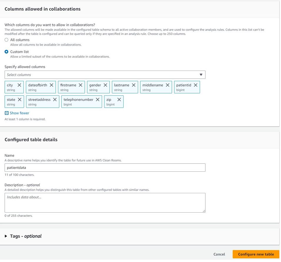
For each selected table, you can determine which columns can be accessed in the collaboration.

  1. Select All columns or select Custom list to choose a subset of columns to be available in the collaboration.
  2. Enter a name for the configured table.
  3. Choose Configure new table.

In addition to column-level access controls, AWS Clean Rooms provides fine-grained query controls called analysis rules. With built-in and flexible analysis rules, you can tailor queries to specific business needs. As discussed earlier, AWS Clean Rooms provides two types of analysis rules:

  • Aggregation analysis rules – These allow queries that aggregate data without revealing row-level information. Available functions include COUNT, SUM, and AVG, along optional dimensions.
  • List analysis rules – These allow queries that output row-level attribute analyses of the overlap between the tables in the collaboration space.

Both rule types allow data owners to mandate a join between their datasets and the datasets of the collaborator running the query. This limits the results to just their intersection of the collaborators datasets.

  1. On the configured table, choose Configure analysis rule to configure the analysis rules.
  2. For this post, we select List because we want to query patients’ immunization status by joining with immunization data from other contributors.
  3. Select the creation method and select Next.
  4. To define the criteria for the table joins, in the Join controls section, choose the column names appropriate for the join.
  5. To specify which columns will be outputted, identify those in the List controls section.
  6. Choose Next.
  7. Choose Configure analysis rule on the Review and configure page.

You will see the message Successfully configured list analysis rule on the configured tables page.

  1. Choose Associate to collaboration to link this table to the collaboration you created.
  2. Review the details on the Associate table page and choose Associate table.

The collaboration page will display a list of tables that are associated by you to the collaboration.
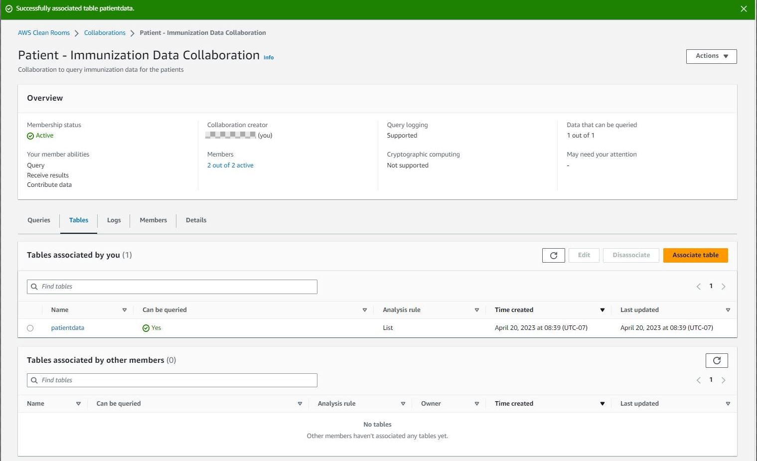
Each member of the collaboration must repeat the aforementioned steps to associate their AWS Glue Data Catalog tables to the collaboration. For this post, the other members of the collaboration follow these same steps to associate their data to the collaboration. Then the collaboration will list all tables associated by other members.
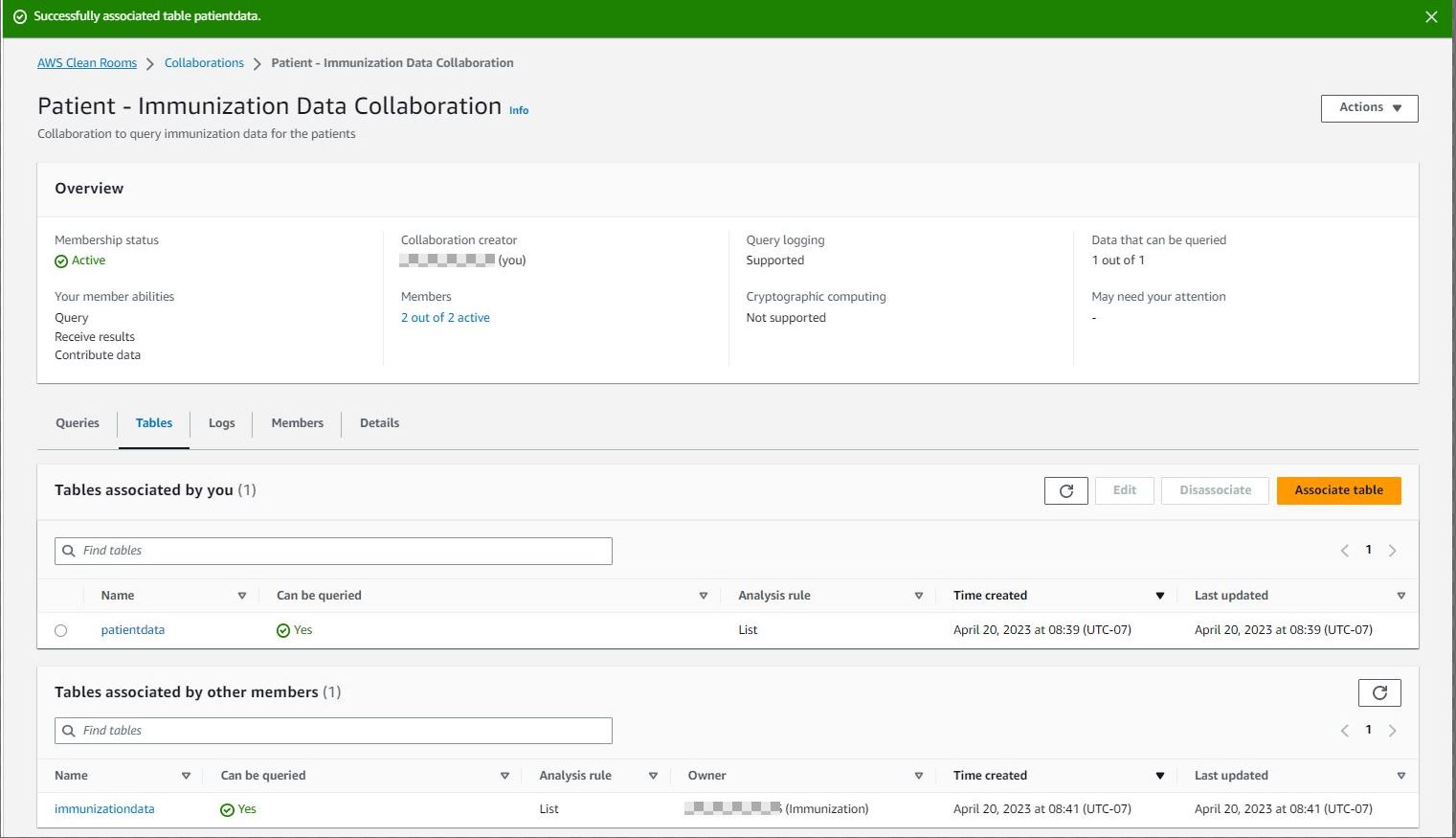
After defining the analysis rules on the configured tables and associating them to the collaboration, the members who can query and receive results can start writing queries according to the restrictions defined by each participating collaboration member. The following section includes example collaboration queries.

Run queries in the collaboration

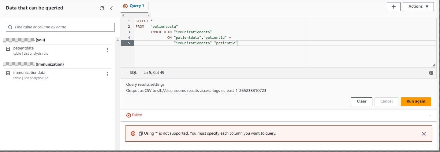
The following screenshot is an example of a query that won’t be successful because * is not supported. Column names must be specified in the query.
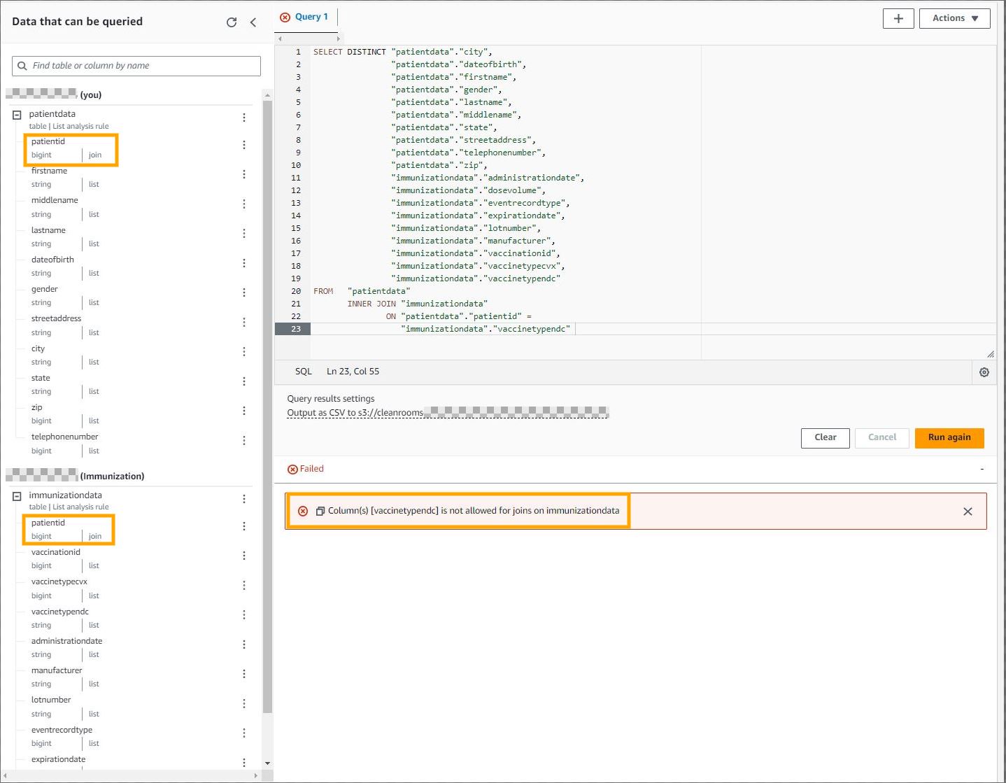
The following screenshot is an example of a query that won’t be successful because you can’t link columns that members restricted in your joins.
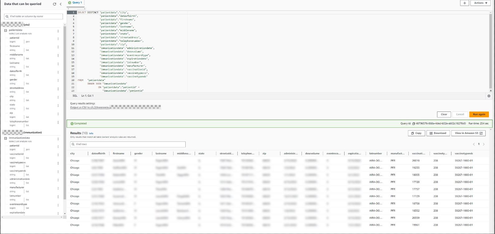
The following screenshot is an example of a query that will be successful because it uses permitted columns (columns that are part of the list analysis rule) in the select clause and join condition.
The sample datasets (Patient and Immunization) used in this post include a unique identifier (patient ID). However, in a real-world scenario, this might not be the case. In those situations, you may consider using privacy-preserving record linkage (PPRL) to create a unique deidentified token. For example, the CDC’s CODI program deduplicates across data owners by obfuscating PII behind each organization’s firewall in a standardized way. That obfuscated information is joined to create a unique deidentified token for each individual that is analyzed across data sources. If public health agencies want to conduct analyses based on individually linked longitudinal data, they could apply PPRL to each data source and use that metadata element to link the data sources in AWS Clean Rooms before conducting their analytics.

Clean up

As part of this walkthrough, you provisioned an AWS Clean Rooms collaboration, invited other members to join the collaboration, and configured tables. To delete these resources, refer to Leaving the collaboration and Disassociating configured tables.

Conclusion

In this post, we showed you how to create a collaboration, invite other members to the collaboration, configure existing AWS Glue Catalog tables, apply analysis rules, and run sample queries on the AWS Clean Rooms console. In Part 2 of this series, we demonstrate how to automate query runs using AWS Lambda, query the results using Amazon Athena, and publish dashboards using Amazon QuickSight.


About the Authors

Venkata Kampana is a Senior Solutions Architect in the AWS Health and Human Services team and is based in Sacramento, CA. In that role, he helps public sector customers achieve their mission objectives with well-architected solutions on AWS.

Dr. Dawn Heisey-Grove is the public health analytics leader for Amazon Web Services’ state and local government team. In this role, she’s responsible for helping state and local public health agencies think creatively about how to achieve their analytics challenges and long-term goals. She’s spent her career finding new ways to use existing or new data to support public health surveillance and research.

Jim Daniel is the Public Health lead at Amazon Web Services. Previously, he held positions with the United States Department of Health and Human Services for nearly a decade, including Director of Public Health Innovation and Public Health Coordinator. Before his government service, Jim served as the Chief Information Officer for the Massachusetts Department of Public Health.

Making Sense of SSD SMART Stats

Post Syndicated from original https://www.backblaze.com/blog/making-sense-of-ssd-smart-stats/

Over the past several years, folks have come to embrace the solid state drive (SSD) as their standard data storage device. It’s gotten to the point where people are breathlessly predicting the imminent death of the venerable hard drive. While we don’t see the demise of the hard drive happening any time soon, SSDs are here to stay and we want to share what we know about them. To that end, we’ve previously compared hard drives and SSDs as it relates to power, reliability, speed, price, and so on.  But, the one area we’ve left primarily unexplored for SSDs is SMART.

SMART—or, more properly, S.M.A.R.T.—stands for Self Monitoring, Analysis, and Reporting Technology. This is a monitoring system built into hard drives and SSDs whose primary function is to detect and report on the state of the drive by populating specific SMART attributes. These include time-in-service and temperature, as well as reliability-based attributes for media condition, operational efficiency, and many more.

Both hard drives and SSDs populate SMART attributes, but given how different these drive types are, the information produced is quite different as well. For example, hard drives have sectors, while SSDs have pages and blocks. Let’s take a look at the common attributes of hard drives and SSDs, and then we’ll dig into the SSD SMART attributes we’ve found useful, interesting, or just weird.

Let’s Get SMARTed

For each SSD model, the drive manufacturer decides which SMART attributes to populate. Attributes are numbered from 1 to 255, with raw and normalized values for each attribute. Some SMART reference material will also list attributes in hexadecimal (HEX), for example, decimal 12 will also be shown as “HEX 0C.”  

At Backblaze, we have over a dozen different SSD models in service, and we pull daily SMART stats from each. To simplify the task at hand for the purposes of this blog post, we chose three SSD models, one each from Seagate, Western Digital, and Crucial, to show the similarities and differences between the models. All three are 250GB SSDs.

To that end, we have created a table of the SMART attributes used by each of those three drive models. You can download a PDF of the table, or jump to the end of this post to view the table.  Things to note about the table:

  • Only 44 of the 255 available attributes are used by these SSDs. Most of the other attributes are exclusive to hard drives or not used at all.
  • The attribute names and definitions were gathered from multiple sources which are referenced at the end of this post. The consistency of the names and definitions across all SSD manufacturers is, well, not as consistent as we would like.
  • Of the 44 attributes listed in the table, the Seagate SSD (model: Seagate BarraCuda 120 SSD ZA250CM10003) uses 20, the Western Digital (model: WDC WDS250G2B0A) uses 25, and the Crucial (model: CT250MX500SSD1) uses 23.
  • The SMART values listed for each SSD model are those that were recorded using the smartctl utility from the smartmontools package. 

One of the things you’ll notice as you examine the list of attributes is that there are several which have similar names, but are different attribute numbers. That is, different vendors use a different attribute for basically the same thing. This highlights a deficiency in SMART:  Participation is voluntary. While the vendors try to play nice with each other, who uses a given attribute for what purpose is subject to the whims, patience, and persistence of the many SSD manufacturers in the market today.

Often manufacturers have created their own SMART monitoring tools to use on their drives. As they add, change, and delete the SMART attributes they use, they update their tools. Drive agnostic tools such as smartctl, which we use, have to chase down updates that have occurred in each of the manufacturer’s homegrown SMART monitoring tools. There are other tools out there as well. DriveDX is another vendor-agnostic SSD monitoring tool, and here’s a link to their release notes page. They made 38 updates in release 1.10.0 (700) alone just to keep up with the drive manufacturers.

Making things more complicated, manufacturers differ widely in how they advertise the attributes and definitions they use. Kingston, for example, is very good about publishing a table of named SMART attributes and definitions for each of their drives, whereas similar information for Western Digital SSDs is difficult to find in the public domain. The net result is that agnostic SMART tools such as smartctl, DriveDx, and others have to work extra hard to keep up with new, updated, and deleted attributes.

Common Attributes

Of the 44 attributes we list in our table, only five are common for all three of the SSD models we are examining. Let’s start with the three of the common attributes that are also common to nearly every hard drive in production today.

  • SMART 9: Power-On Hours. The count of hours in power-on state.
  • SMART 12: Power Cycle Count. The number of times the disk is powered off and then powered back on. This is cumulative over the life of the drive.
  • SMART 194: Temperature. The internal temperature of the drive. For some drive models, the normalized value ranges from 0 to 255, for other drive models the range is 0 to 100, and for others the normalized value is the same as the raw value. In all cases, the raw value is in degrees Celsius.

SSD Unique Common Attributes

These two attributes are specific to SSDs and are common to all three of the models we are examining.

  • SMART 173: SSD Wear Leveling. Counts the maximum worst erase count on a single block.
  • SMART 174: Unexpected Power Loss Count. The number of unclean (unexpected) shutdowns, like when you kick out the plug of your external drive. This value is cumulative over the life of the SSD. This attribute is a subset of the count for SMART 12 and with a little math you can get the number of normal shutdowns if that is interesting to you.

Not Much In Common

As noted, only five of the 44 SMART attributes are common between our three SSD models. This lack of commonality, 11%, seemed low to us, and we wondered what the commonality was between the SMART attributes on the hard drive models we use. We reviewed the SMART attributes for three 14TB hard drive models in our drive stats data set, one model each from Seagate, Western Digital, and Toshiba. We found that 42% of the SMART attributes were common between the three models. That’s nearly four times more than the SSD commonality, but admittedly less than we thought. 

Useful Attributes

For the purpose at hand, we’ll define a useful attribute as something that clearly indicates the health of the SSD. That led us to focus on two concepts: Lifetime remaining (or used) percentage, and logical block addressing (LBA) read/write counts. Let’s take a look at how each of the drive models reports on these attributes.

Lifetime Percentage

SMART 169: Remaining Lifetime Percentage (Western Digital)

This attribute measures the approximate life left from a combination of program-erase cycles and available reserve blocks of the device. A brand new SSD will report a value of “100” for the Normalized value and decrease down to “0” as the drive is used.

SMART 202: Percentage of Lifetime Used (Crucial)

This attribute measures how much of the drive’s projected lifetime has been used at any point in time. For a brand new drive, the attribute will report “0”, and when its specified lifetime has been reached, it will show “100,” reporting that 100 percent of the lifetime has been used. 

SMART 231: Life Left (Seagate)

This attribute indicates the approximate SSD life left, in terms of program/erase cycles or available reserved blocks. A brand new SSD has a normalized value of “100” and decreases from there with a threshold value at “10” indicating a need for replacement. A value of “0” may mean that the drive is operating in read-only mode.

All three use program/erase cycles (SMART 232) and available reserved blocks (SMART 170) to compute their percentages, although as is seen, SMART 202 counts up, while the other two count down. Lifetime, as defined here, is relative. That is you could be at 50% lifetime after six months or six years depending on the SSD usage. 

LBAs Written/Read

In an SSD, data is written to and read from a page, also known as a NAND page. A group of pages forms a block. The LBA written/read count is just that, a count of blocks written/read. Each time a block is written or read the respective SMART attribute counter increases by one. For example, if various pieces of data on the pages within a single block are read 10 times, it will increase the SMART counter by 10. 

SMART 241: LBAs Written (Seagate and Western Digital) 

Total count of LBAs written.

SMART 242: LBAs Read (Seagate and Western Digital)  

Total count of LBAs read.

SMART 246: Cumulative Host Sectors Written (Crucial)  

LBAs written due to a computer request. Note that the name of this attribute seems incorrect as it states sectors versus blocks. 

Crucial also counts NAND pages written due to a computer request (SMART 247) and NAND pages written due to a background operation such as garbage collection (SMART 248). Crucial does not seem to have a SMART attribute for total count of LBAs read. Nor does it seem to record LBAs written for background operations.

Interesting Attributes

Below we’ve gathered several SSD SMART attributes we found interesting and one could argue potentially useful. In no particular order, let’s take a look.

SMART 230: Drive Life Protection Status (Western Digital)

This attribute indicates whether the SSD’s usage trajectory is outpacing the expected life curve. This attribute implies a couple of interesting things. First, there is a usage trajectory calculation and value. This could be SMART 169 noted previously. Second, there is a defined expected life. We assume that the expected life curve is fixed for a given SSD model and perhaps uses the warranty period as its zero date, but we’re only guessing here. 

SMART 210: RAIN Successful Recovery Page Count (Crucial)

Redundant Array of Independent NAND (RAIN) is similar to gaining data redundancy using RAID in a drive array, except RAIN redundancy is accomplished within the drive, i.e., all the data written to this SSD is made redundant on the SSD itself. This redundancy is not free and either consumes some of disk space from the total space specified (250GB in this case), or uses additional space not counted in the total. Either way, this is a really cool feature and allows for data to be recovered transparently to the user even when initially it couldn’t be read due to a bad page or block.

SMART 232: Endurance Remaining (Seagate and Western Digital)

The number of physical erase cycles completed on the SSD as a percentage of the maximum physical erase cycles the drive is designed to endure. At first look, this seems similar to SMART 231 (Life Left), but this attribute does not consider available reserved blocks as part of its calculus. Still, this attribute could be a harbinger of what’s to come, as erasing SSD blocks at an accelerated rate often leads to having to utilize available reserved blocks downstream as the SSD cells wear out.

SMART 233: Media Wearout Indicator (Seagate and Western Digital)

Similar to SMART 232 (but without the math) as this attribute records the count of the actual NAND erase cycles. The normalized value starts at 100 for a new drive and decreases to a minimum of 1. As it decreases, the NAND erase cycles count (raw value) increases from 0 to the maximum-rated number of cycles.

SMART 171: SSD Program Fail Count (Western Digital and Crucial) and SMART 172: SSD Erase Count Fail (Western Digital and Crucial)

Both of these attributes count their respective failures (Program Fail and Erase Count) from when the drive was deployed. As a drive ages, one would expect these counts to increase and eventually pass some threshold value which would indicate a problem. While this is helpful in determining the health of a drive, these attributes alone provide only a partial picture as they can miss a rapid acceleration of failures over a short period of time. 

Weird Things

There are a handful of attributes which seem odd based on our table and the attribute names and the definitions we have found. We’d like to point these out to start the conversation—If anyone can shed some light on these oddities, jump in the comments. Your input is much appreciated.

SMART 16: Total LBAs Read (Seagate)

There are two odd things here. First, the definition states that this attribute is only found on select Western Digital hard drive models—yet it was found in most of our Seagate SSDs. This could be a definition problem, but then there’s the second thing: Seagate SSDs record Total LBAs Read in attribute 242 (noted above). So, it seems it could also be an attribute name problem. 

SMART 17: Unknown (Seagate)

We could not find any information on SMART 17, except for the fact that our Seagate drives report on this attribute. 

SMART 196: Reallocation Event Count (Crucial), SMART 197: Current Pending Sector Count (Crucial), and SMART 198: Uncorrectable Sector Count (Crucial)

Our Crucial drives report values for these attributes, but this is another case where the names and definitions don’t make sense, as they are talking about sectors which are hard drive-specific.

SMART 206: Flying Height (Crucial)

Another attribute reported by our Crucial drives which makes no sense based on the name and definition. I think we can all agree that measuring the flying height of the cells within an SSD is not meaningful.

The questions around the Crucial reported attributes could be straightforward to answer as Crucial has their own free SMART monitoring software, Storage Executive. If you are using this software, we’d appreciate any info you can share on the Crucial names and definitions of these attributes.

Data Retention

Many of us have an external hard drive or two sitting on a shelf somewhere acting as a backup or perhaps even an archive of our data. Every so often, we take out one of those drives, plug it in, and hope it spins up. This can go on for years. 

Can SSDs be used for offline data storage, and if so how long can they safely remain unplugged? It’s a good question and one that has been debated many times over the years with time frames ranging from a few weeks to several years. The current thinking is that when an SSD is new, it can safely store your data without power for a year or so, but as the drive wears out the data retention period begins to diminish. 

This begs the question: How worn out is your SSD? For Crucial SSDs, the answer is SMART 202: Percentage Lifetime Used. We discussed this attribute earlier in relation to drive life, but it also plays a role in data retention when the drive is unpowered. Using the normalized value, Crucial estimates the following: 

  • “0” indicates that the drive can be stored unpowered for up to one year.
  • “50” indicates that the drive can be stored unpowered for up to six months.
  • “100” indicates that the drive can be stored unpowered for up to one month. 
  • Anything above “100” and your data is at risk when the SSD is powered off.

In theory, you should be able to use the SMART 231: Life Left (Seagate) or SMART 169: Remaining Lifetime Percentage (Western Digital) to perform the same analysis as was done above with SMART 202 and the Crucial SSD model. Remember that these two attributes (231 and 169) count downward, that is “100” is good and “0” is bad. All that said, this is just a theory, as we’ve found no documentation this is actually the case (but it does seem to make sense).

SMART Could Be Even SMARTer

It’s great that SSD manufacturers are using SMART attributes to record relevant information about the status and health of their drive models. It’s also great that many manufacturers also provide software that monitors these SMART stats and provides the user feedback. All is wonderful when you are buying all your SSDs from the same manufacturer. But that’s just not the reality for most IT shops who are managing servers, networking gear, and so on from different vendors. It is also not the reality when it comes to running a cloud storage company. 

Having accurate, up-to-date, vendor agnostic SSD monitoring tools is important to many organizations as part of their ability to cost effectively manage their systems and keep them healthy. Having to use a multitude of different tools to monitor SSDs doesn’t benefit anyone. Maybe it’s time we take SMART for SSDs beyond voluntary and look to standardize the attributes and their names and definitions across the board for all SSD manufacturers.

Sources

Multiple sources were consulted in researching this post, they are listed below. We may have missed one or two sources, and we apologize in advance if we did.

  • https://en.wikipedia.org/wiki/Self-Monitoring,_Analysis_and_Reporting_Technology
  • https://en.wikipedia.org/wiki/Solid-state_drive
  • https://media.kingston.com/support/downloads/KC600-SMART-attribute.pdf
  • https://media.kingston.com/support/downloads/MKP_521_Phison_SMART_attribute.pdf
  • https://media.kingston.com/support/downloads/MKP_306_SMART_attribute.pdf
  • https://www.cropel.com/library/smart-attribute-list.aspx
  • https://www.crucial.com/support/articles-faq-ssd/ssds-and-smart-data
  • https://www.micromat.com/product_manuals/drive_scope_manual_01.pdf
  • https://www.recoverhdd.com/blog/smart-data-for-ssd-drive.html

We only used sources which are available to us without purchasing something. That is, we didn’t buy agnostic monitoring applications or purchase a specific manufacturer’s SSD to have something to use their free monitoring application on. We took our Drive Stats data and then, just like you, we ventured into the internet to search out SSD SMART attribute information that was publicly available.

SMART Attributes Table

The following table contains the SMART attributes for the three SSD models listed. These attributes are collected by the smartctl utility within the smartmon toolset.

The post Making Sense of SSD SMART Stats appeared first on Backblaze Blog | Cloud Storage & Cloud Backup.

Enable remote reads from Azure ADLS with SAS tokens using Spark in Amazon EMR

Post Syndicated from Kiran Anand original https://aws.amazon.com/blogs/big-data/enable-remote-reads-from-azure-adls-with-sas-tokens-using-spark-in-amazon-emr/

Organizations use data from many sources to understand, analyze, and grow their business. These data sources are often spread across various public cloud providers. Enterprises may also expand their footprint by mergers and acquisitions, and during such events they often end up with data spread across different public cloud providers. These scenarios can create the need for AWS services to remotely access, in an ad hoc and temporary fashion, data stored in another public cloud provider such as Microsoft Azure to enable business as usual or facilitate a transition.

In such scenarios, data scientists and analysts are presented with a unique challenge when working to complete a quick data analysis because data typically has to be duplicated or migrated to a centralized location. Doing so introduces time delays, increased cost, and higher complexity as pipelines or replication processes are stood up by data engineering teams. In the end, the data may not even be needed, resulting in further loss of resources and time. Having quick, secure, and constrained access to the maximum amount of data is critical for enterprises to improve decision-making. Amazon EMR, with its open-source Hadoop modules and support for Apache Spark and Jupyter and JupyterLab notebooks, is a good choice to solve this multi-cloud data access problem.

Amazon EMR is a top-tier cloud big data solution for petabyte-scale data processing, interactive analytics, and machine learning using open-source frameworks such as Apache Spark, Apache Hive, and Presto. Amazon EMR Notebooks, a managed environment based on Jupyter and JupyterLab notebooks, enables you to interactively analyze and visualize data, collaborate with peers, and build applications using EMR clusters running Apache Spark.

In this post, we demonstrate how to set up quick, constrained, and time-bound authentication and authorization to remote data sources in Azure Data Lake Storage (ADLS) using a shared access signature (SAS) when running Apache Spark jobs via EMR Notebooks attached to an EMR cluster. This access enables data scientists and data analysts to access data directly when operating in multi-cloud environments and join datasets in Amazon Simple Storage Service (Amazon S3) with datasets in ADLS using AWS services.

Overview of solution

Amazon EMR inherently includes Apache Hadoop at its core and integrates other related open-source modules. The hadoop-aws and hadoop-azure modules provide support for AWS and Azure integration, respectively. For ADLS Gen2, the integration is done through the abfs connector, which supports reading and writing data in ADLS. Azure provides various options to authorize and authenticate requests to storage, including SAS. With SAS, you can grant restricted access to ADLS resources over a specified time interval (maximum of 7 days). For more information about SAS, refer to Delegate access by using a shared access signature.

Out of the box, Amazon EMR doesn’t have the required libraries and configurations to connect to ADLS directly. There are different methods to connect Amazon EMR to ADLS, and they all require custom configurations. In this post, we focus specifically on connecting from Apache Spark in Amazon EMR using SAS tokens generated for ADLS. The SAS connectivity is possible in Amazon EMR version 6.9.0 and above, which bundles hadoop-common 3.3.0 where support for HADOOP-16730 has been implemented. However, although the hadoop-azure module provides a SASTokenProvider interface, it is not yet implemented as a class. For accessing ADLS using SAS tokens, this interface should be implemented as a custom class JAR and presented as a configuration within the EMR cluster.

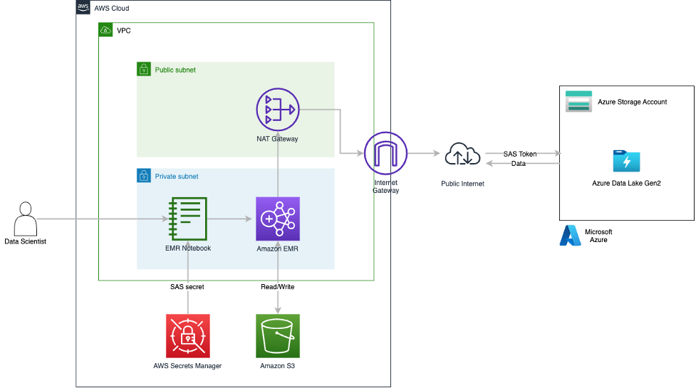
You can find a sample implementation of the SASTokenProvider interface on GitHub. In this post, we use this sample implementation of the SASTokenProvider interface and package it as a JAR file that can be added directly to an EMR environment on version 6.9.0 and above. To enable the JAR, a set of custom configurations are required on Amazon EMR that enable the SAS token access to ADLS. The provided JAR needs to be added to the HADOOP_CLASSPATH, and then the HADOOP_CLASSPATH needs to be added to the SPARK_DIST_CLASSPATH. This is all handled in the sample AWS CloudFormation template provided with this post. At a high level, the CloudFormation template deploys the Amazon EMR cluster with the custom configurations and has a bootstrapping script that stages the JAR on the nodes of the EMR cluster. The CloudFormation template also stages a sample Jupyter notebook and datasets into an S3 bucket. When the EMR cluster is ready, the EMR notebook needs to be attached to it and the sample Jupyter notebook loaded. After the SAS token configurations are done in the notebook, we can start reading data remotely from ADLS by running the cells within the notebook. The following diagram provides a high-level view of the solution architecture.

Architecture Overview

We walk through the following high-level steps to implement the solution:

  1. Create resources using AWS CloudFormation.
  2. Set up sample data on ADLS and create a delegated access with an SAS token.
  3. Store the SAS token securely in AWS Secrets Manager.
  4. Deploy an EMR cluster with the required configurations to securely connect and read data from ADLS via the SAS token.
  5. Create an EMR notebook and attach it to the launched EMR cluster.
  6. Read data via Spark from ADLS within the JupyterLab notebook.

For this setup, data is going over the public internet, which is not a best practice nor an AWS recommendation, but it’s sufficient to showcase the Amazon EMR configurations that enable remote reads from ADLS. Solutions such as AWS Direct Connect or AWS Site-to-Site VPN should be utilized to secure data traffic in enterprise deployments.

For an AWS Command Line Interface (AWS CLI)-based deployment example, refer to the appendix at the end of this post.

Prerequisites

To get this solution working, we have a set of prerequisites for both AWS and Microsoft Azure:

  • An AWS account that can create AWS Identity and Access Management (IAM) resources with custom names and has access enabled for Amazon EMR, Amazon S3, AWS CloudFormation, and Secrets Manager.
  • The old Amazon EMR console enabled.
  • An Azure account with a storage account and container.
  • Access to blob data in ADLS with Azure AD credentials. The user must have the required role assignments in Azure. Refer to Assign an Azure role for more details.

We are following the best practice of using Azure AD credentials to create a user delegation SAS when applications need access to data storage using shared access signature tokens. In this post, we create and use a user delegation SAS with read and list permissions for ADLS access. For more information about creating SAS tokens using the Azure portal, refer to Use the Azure portal.

Before we generate the user delegation SAS token, we need to ensure the credential that will be used to generate the token has appropriate permissions to access data on the ADLS storage account. Requests submitted to the ADLS account using the user delegation SAS token are authorized with the Azure AD credentials that were used to create the SAS token.

The following minimum Azure role-based access control is required at the storage account level to access the data on ADLS storage:

  • Reader – Allow viewing resources such as listing the Azure storage account and its configuration
  • Storage Blob Data Reader – Allow reading and listing Azure storage containers and blobs
  • Storage Blob Delegator – In addition to the permissions to access the data on the ADLS account, you also need this role to generate a user delegation SAS token

Create an EMR cluster and S3 artifacts with AWS CloudFormation

To create the supported version of an EMR cluster with the required SAS configurations and stage all the required artifacts in Amazon S3, complete the following steps:

  1. Sign in to the AWS Management Console in your Region (for this post, we use us-east-1).
  2. Choose Launch Stack to deploy the CloudFormation template:
  3. Choose Next.

Create Stack

  1. For Stack name, enter an appropriate lowercase name.
  2. For EmrRelease, leave as default.

As of this writing, the stack has been tested against 6.9.0 and 6.10.0.

  1. Choose Next.
    Stack Details
  2. On the next page, choose Next.
  3. Review the details and select I acknowledge that AWS CloudFormation might create IAM resources with custom names.
  4. Choose Create stack.
  5. Monitor the progress of the stack creation until it’s complete (about 15–20 minutes).
  6. When the stack creation is complete, navigate to the stack detail page.
  7. On the Resources tab, find the logical ID with the name S3ArtifactsBucket.
  8. Choose the link for the physical ID that starts with emr-spark-on-adls-<GUID> to be redirected to the bucket on the Amazon S3 console.
  9. On the Objects tab, open the EMR/ folder.
    S3 Bucket
  10. Open the artifacts/ folder.

There are five artifacts staged by the CloudFormation stack in this path:

  • azsastknprovider-1.0-SNAPSHOT.jar – The custom implementation of the SASTokenProvider interface.
  • EMR-Direct-Read-From-ADLS.ipynb – The Jupyter notebook that we’ll use with the EMR cluster to read data from ADLS.
  • env-staging.sh – A bash script that the Amazon EMR bootstrap process runs to stage azsastknprovider-1.0-SNAPSHOT.jar across cluster nodes.
  • Medallion_Drivers_-_Active.csv – A sample dataset that needs to be staged in the ADLS container from which we will read.
  • self-signed-certs.zip – The openSSL self-signed certificates used by AWS CloudFormation to encrypt data in transit. This example is a proof of concept demonstration only. Using self-signed certificates is not recommended and presents a potential security risk. For production systems, use a trusted certification authority (CA) to issue certificates.
  1. Select Medallion_Drivers_-_Active.csv and choose Download.
  2. Select EMR-Direct-Read-From-ADLS.ipynb and choose Download.

Create the SAS token and stage sample data

To generate the user delegation SAS token from the Azure portal, log in to the Azure portal with your account credentials and complete the following steps:

  1. Navigate to Storage account, Access Control, and choose Add role assignment.
  2. Add the following roles to your user: Reader, Storage Blob Data Reader, and Storage Blob Delegator.
  3. Navigate to Storage account, Containers, and choose the container you want to use.
  4. Under Settings in the navigation pane, choose Shared access tokens.
  5. Select User delegation key for Signing method.
  6. On the Permissions menu, select Read and List.
    ADLS Container
  7. For Start and expiry date/time, define the start and expiry times for the SAS token.
  8. Choose Generate SAS token and URL.
  9. Copy the token under Blob SAS token and save this value.
    SAS Token
  10. Choose Overview in the navigation pane.
  11. Choose Upload and upload the Medallion_Drivers_-_Active.csv file downloaded earlier.

Store the SAS token in Secrets Manager

Next, we secure the SAS token in Secrets Manager so it can be programmatically pulled from the Jupyter notebook.

  1. Open the Secrets Manager console in the same Region you have been working in (in this case, us-east-1).
  2. Choose Store a new secret.
  3. For Secret type, select Other type of secret.
  4. In the Key/value pairs section, enter a name for the key and enter the blob SAS token for the value.
  5. For Encryption key, choose the default AWS managed key.
  6. Choose Next.
    Secret Type
  7. For Secret name, enter a name for your secret.
  8. Leave the optional fields as default and choose Next.
  9. On the next page, leave the settings as default and choose Next.

Setting up a secret rotation is a best practice but out of scope for this post. You can do so via Azure RM PowerShell, which can be integrated with the Lambda rotation function from Secrets Manager.

  1. Choose Store.
  2. Refresh the Secrets section and choose your secret.
  3. In the Secret details section, copy the value for Secret ARN to use in the Jupyter notebook.
    Secret ARN

Configure an EMR notebook with the SAS token and read ADLS data

Finally, we create the EMR notebook environment, integrate the SAS token into the downloaded Jupyter notebook, and perform a read against ADLS.

  1. Open the Amazon EMR console in the same Region you have been working in (in this case. us-east-1).
  2. Under EMR on EC2 in the navigation pane, choose Clusters.
  3. In the cluster table, choose Cluster with ADLS SAS Access.
    EMR Cluster

On the Summary tab, you will find the applications deployed on the cluster.

EMR Summary Tab

On the Configurations tab, you can see the configurations deployed by the CloudFormation stack loading the customer JAR in the appropriate classpaths.

EMR Configurations Tab

  1. Under EMR on EC2 in the navigation pane, choose Notebooks.
  2. Choose Create notebook.
  3. Enter an appropriate name for the notebook for Notebook name.
  4. For Cluster, select Choose an existing cluster, then choose the cluster you created earlier.
  5. Leave all other settings as default and choose Create notebook.
    Create Notebook
  6. When the notebook environment is set up, choose Open in JupyterLab.
  7. On your local machine, navigate to where you saved the EMR-Direct-Read-From-ADLS.ipynb notebook.
  8. Drag and drop it into the left pane of the JupyterLab environment.
  9. Choose EMR-Direct-Read-From-ADLS.ipynb from the left pane and ensure that the interpreter selected for the notebook in the top-right corner is PySpark.
    Open Notebook
  10. In the notebook, under the SAS TOKEN SETUP markup cell, replace <AWS_REGION> with the Region you are using (in this case, us-east-1).
  11. In the same code cell, replace <ADLS_SECRET_MANAGER_SECRET_ARN> with your secret ARN and <SECRET_KEY> with your secret key.

You can get the secret key from Secrets Manager in the Secret value section for the secret you created earlier.

Secret Key

  1. In the code cell below the HADOOP CONFIGURATIONS markup cell, replace <YOUR_STORAGE_ACCOUNT> with your Azure storage account where the SAS token was set up earlier.
  2. In the code cell below the READ TEST DATA markup cell, replace <YOUR_CONTAINER> and <YOUR_STORAGE_ACCOUNT> with your Azure container and storage account name, respectively.
  3. On the Run menu, choose Run All Cells.
    Run All Cells

After all notebook cells run, you should see 10 rows in a tabular format containing the data coming from ADLS, which now can be used directly in the notebook or can be written to Amazon S3 for further use.

Results

Clean up

Deploying a CloudFormation template incurs cost based on the resources deployed. The EMR cluster is configured to stop after an hour of inactivity, but to avoid incurring ongoing charges and to fully clean up the environment, complete the following steps:

  1. On the Amazon EMR console, choose Notebooks in the navigation pane.
  2. Select the notebook you created and choose Delete, and wait for the delete to complete before proceeding to the next step.
  3. On the Amazon EMR console, choose Clusters in the navigation pane.
  4. Select the cluster Cluster With ADLS SAS Access and choose Terminate.
  5. On the Amazon VPC console, choose Security groups in the navigation pane.
  6. Find the ElasticMapReduce-Master-Private, ElasticMapReduce-Slave-Private, ElasticMapReduce-ServiceAccess, ElasticMapReduceEditors-Livy, and ElasticMapReduceEditors-Editor security groups attached to the VPC created by the CloudFormation stack and delete their inbound and outbound rules.
  7. Select these five security groups and on the Actions menu, choose Delete security groups.
  8. On the AWS CloudFormation console, choose Stacks in the navigation pane.
  9. Select the stack and choose Delete.
  10. On the Secrets Manager console, choose Secrets in the navigation pane.
  11. Select the stored SAS secret and on the Actions menu, choose Delete secret.
  12. On the IAM console, choose Roles in the navigation pane.
  13. Select the role EMR_Notebooks_DefaultRole and choose Delete.

Conclusion

In this post, we used AWS CloudFormation to deploy an EMR cluster with the appropriate configurations to connect to Azure Data Lake Storage using SAS tokens over the public internet. We provided an implementation of the SASTokenProvider interface to enable the SAS token-based connectivity to ADLS. We also provided relevant information on the SAS token creation steps on the Azure side. Furthermore, we showed how data scientists and analysts can use EMR notebooks connected to an EMR cluster to read data directly from ADLS with a minimum set of configurations. Finally, we used Secrets Manager to secure the storage of the SAS token and integrated it within the EMR notebook.

We encourage you to review the CloudFormation stack YAML template and test the setup on your own. If you implement the example and run into any issues or just have feedback, please leave a comment.


Appendix

AWS CLI-based deployment model

If you prefer to use command line options, this section provides AWS CLI commands to deploy this solution. Note that this is an alternative deployment model different from the CloudFormation template provided in the previous sections. Sample scripts and commands provided here include placeholders for values that need to be updated to suit your environment. The AWS CLI commands provided in this section should be used as guidance to understand the deployment model. Update the commands as needed to follow all the security procedures required by your organization.

Prerequisites for an AWS CLI-based deployment

The following are the assumptions made while using this AWS CLI-based deployment:

  • You will be deploying this solution in an existing AWS environment that has all the necessary security configurations enabled
  • You already have an Azure environment where you have staged the data that needs to be accessed through AWS services

You must also complete additional requirements on the AWS and Azure sides.

For AWS, complete the following prerequisites:

  1. Install the AWS CLI on your local computer or server. For instructions, see Installing, updating, and uninstalling the AWS CLI.
  2. Create an Amazon Elastic Compute Cloud (Amazon EC2) key pair for SSH access to your Amazon EMR nodes. For instructions, see Create a key pair using Amazon EC2.
  3. Create an S3 bucket to store the EMR configuration files, bootstrap shell script, and custom JAR file. Make sure that you create a bucket in the same Region as where you plan to launch your EMR cluster.
  4. Copy and save the SAS token from ADLS to use in Amazon EMR.

For Azure, complete the following prerequisites:

  1. Generate the user delegation SAS token on the ADLS container where your files are present, with the required levels of access granted. In this post, we are use SAS tokens with only read and list access.
  2. Copy and save the generated SAS token to use with Amazon EMR.

Update configurations

We have created a custom class that implements the SASTokenProvider interface and created a JAR file called azsastknprovider-1.0-SNAPSHOT.jar, which is provided as a public artifact for this post. A set of configurations are required on the Amazon EMR side to use the SAS tokens to access ADLS. A sample configuration file in JSON format called EMR-HadoopSpark-ADLS-SASConfig.json is also provided as a public artifact for this post. Download the JAR and sample config files.

While copying the code or commands from this post, make sure to remove any control characters or extra newlines that may get added.

  1. Create a shell script called env-staging-hadoopspark.sh to copy the custom JAR file azsastknprovider-1.0-SNAPSHOT.jar (provided in this post) to the EMR cluster nodes’ local storage during the bootstrap phase. The following code is a sample bootstrap shell script:
    #!/bin/bash
    # Stage the SASTokenProvider interface implementation jar on the local filesystem
    sudo mkdir /lib/customjars
    sudo aws s3 cp s3://<s3 bucket>/<path>/azsastknprovider-1.0-SNAPSHOT.jar /lib/customjars
    sudo chmod 755 /lib/customjars

  2. Update the bootstrap shell script to include your S3 bucket and the proper path where the custom JAR file is uploaded in your AWS environment.
  3. Upload the JAR file, config file, and the bootstrap shell script to your S3 bucket.
  4. Keep a copy of the updated configuration file EMR-HadoopSpark-ADLS-SASConfig.json locally in the same directory from where you plan to run the AWS CLI commands.

Launch the EMR cluster using the AWS CLI

We use the create-cluster command in the AWS CLI to deploy an EMR cluster. We need a bootstrap action at cluster creation to copy the custom JAR file to the EMR cluster nodes’ local storage. We also need to add a few custom configurations on Amazon EMR to connect to ADLS. For this, we need to supply a configuration file in JSON format. The following code launches and configures an EMR cluster that can connect to your Azure account and read objects in ADLS through Hadoop and Spark:

aws emr create-cluster \
--name "Spark Cluster with ADLS Access" \
--release-label emr-6.10.0 \
--applications Name=Hadoop Name=Spark \
--ec2-attributes KeyName=<key pair name> \
--instance-type m5.xlarge \
--instance-count 3 \
--use-default-roles \
--enable-debugging \
--log-uri s3://<s3 bucket>/<logs path>/ \
--configurations file://EMR-HadoopSpark-ADLS-SASConfig.json \
--bootstrap-actions Path="s3://<s3 bucket>/<path>/env-staging-hadoopspark.sh"

Additional configurations for Spark jobs

The following additional properties should be set inside your Spark application code to access data in ADLS through Amazon EMR. These should be set on the Spark session object used within your Spark application code.

spark.conf.set("fs.azure.account.auth.type.<azure storage account>.dfs.core.windows.net", "SAS")
spark.conf.set("fs.azure.sas.token.provider.type.<azure storage account>.dfs.core.windows.net", "org.apache.hadoop.fs.azurebfs.sas.FixedSASTokenProvider")
spark.conf.set("fs.azure.sas.fixed.token.<azure storage account>.dfs.core.windows.net", "<Your SAS token from ADLS - remove the first character if it is &>")

These additional configurations can be set in the core-site.xml file for the EMR cluster. However, setting these in the application code is more secure and recommended because it won’t expose the SAS token in the Amazon EMR configurations.

Submit the Spark application in Amazon EMR using the AWS CLI

You can run a Spark application on Amazon EMR in different ways:

  • Log in to an EMR cluster node through SSH using the EC2 key pair you created earlier and then run the application using spark-submit
  • Submit a step via the console while creating the cluster or after the cluster is running
  • Use the AWS CLI to submit a step to a running cluster:
aws emr add-steps \
--cluster-id <cluster-id> \
--steps 'Type=Spark,Name=Read-ADLS-Data,ActionOnFailure=CONTINUE,Args=[s3://<s3 bucket>/<path>/<spark-application>,—deploy-mode,cluster]'

To read files in ADLS within a Spark application that is running on an EMR cluster, you need to use the abfs driver and refer to the file in the following format, just as you would have done in your Azure environment:

abfs://<azure container name>@<azure storage account>.dfs.core.windows.net/<path>/<file-name>

The following sample PySpark script reads a CSV file in ADLS using SAS tokens and writes it to Amazon S3, and can be run from the EMR cluster you created:

from pyspark import SparkContext
from pyspark.sql import SQLContext, SparkSession
spark = SparkSession.builder.appName('Read data from ADLS').getOrCreate()
spark.conf.set("fs.azure.account.auth.type.<azure storage account>.dfs.core.windows.net", "SAS")
spark.conf.set("fs.azure.sas.token.provider.type.<azure storage account>.dfs.core.windows.net", "org.apache.hadoop.fs.azurebfs.sas.FixedSASTokenProvider")
spark.conf.set("fs.azure.sas.fixed.token.<azure storage account>.dfs.core.windows.net", "<Your SAS token from ADLS>")
adlsDF = spark.read.csv("abfs://<azure container name>@<azure storage account>.dfs.core.windows.net/<path>/<file.csv>")
adlsDF.write.csv("s3://<s3 bucket>/<path>/")

Clean up using the AWS CLI

Delete the EMR cluster created using the delete-cluster command.


About the authors

Kiran Anand is a Principal Solutions Architect with the AWS Data Lab. He is a seasoned professional with more than 20 years of experience in information technology. His areas of expertise are databases and big data solutions for data engineering and analytics. He enjoys music, watching movies, and traveling with his family.

Andre Hass is a Sr. Solutions Architect with the AWS Data Lab. He has more than 20 years of experience in the databases and data analytics field. Andre enjoys camping, hiking, and exploring new places with his family on the weekends, or whenever he gets a chance. He also loves technology and electronic gadgets.

Stefan Marinov is a Sr. Solutions Architecture Manager with the AWS Data Lab. He is passionate about big data solutions and distributed computing. Outside of work, he loves spending active time outdoors with his family.

Hari Thatavarthy is a Senior Solutions Architect on the AWS Data Lab team. He helps customers design and build solutions in the data and analytics space. He believes in data democratization and loves to solve complex data processing-related problems.

Hao Wang is a Senior Big Data Architect at AWS. Hao actively works with customers building large scale data platforms on AWS. He has a background as a software architect on implementing distributed software systems. In his spare time, he enjoys reading and outdoor activities with his family.

Security updates for Thursday

Post Syndicated from original https://lwn.net/Articles/934802/

Security updates have been issued by Debian (webkit2gtk), Fedora (python-django-filter and qt), Mageia (cups, firefox/nss, httpie, thunderbird, and webkit2), Red Hat (.NET 6.0, .NET 7.0, c-ares, firefox, jenkins and jenkins-2-plugins, nodejs, nodejs:18, python3, python3.11, python3.9, and thunderbird), Scientific Linux (firefox and thunderbird), SUSE (frr, opensc, python3, and rekor), and Ubuntu (c-ares, glib2.0, libcap2, linux-intel-iotg-5.15, pano13, and requests).

Young people designed 15,000 images for astronauts in Astro Pi Mission Zero 2022/23

Post Syndicated from Fergus Kirkpatrick original https://www.raspberrypi.org/blog/15000-young-people-astro-pi-mission-zero-2022-23/

In the Columbus module of the International Space Station (ISS), there are two Astro Pi computers called Marie Curie and Nikola Tesla. These computers run the programs young people create as part of the annual European Astro Pi Challenge.

A young person takes part in Astro Pi Mission Zero.

For this year’s Astro Pi Mission Zero, young people sent us over 15,000 programs to show the ISS astronauts colourful images and animations of animals and plants on the Astro Pi displays and remind them of home.

Logo of Mission Zero, part of the European Astro Pi Challenge.

A space mission inspired by nature

Mission Zero is a free beginners’ coding activity. It gives young people the unique opportunity to follow our step-by-step guide to write a simple program in Python that can run in space on the ISS orbiting planet Earth.

The mark 2 Astro Pi units spin in microgravity on the International Space Station.
The Astro Pi computers on board the ISS

The Mission Zero activity this year was to write code to use the Astro Pi’s colour sensor to measure the lighting conditions in the Columbus module, and to then use that measurement to set a colour in an image or animation on the Astro Pi’s 8×8 LED display. We invited young people to design images of fauna and flora to give the astronauts on board the ISS a reminder of the beautiful creatures, plantlife, and landscapes found on planet Earth.

A selection of pixel images of animals and plants, which young people coded for Astro Pi Mission Zero.

The Mission Zero activity is ideal for learners trying text-based programming for the first time. It covers some key programming concepts, including variables, sequence, and iteration.

Tens of thousands of young people had their programs run in space

This year we received 15,551 Mission Zero programs, and after carefully checking them against the entry and safety criteria, we were able to run 15,475 programs. They were sent to us by 23,605 learners working in teams or independently, and 10,207 of this year’s participants were girls.

A young person with her coding project at a laptop.

This year the most Mission Zero programs came from young people in the UK, followed by Spain, France, Italy, and Greece. Lots of different organisations supported young people to take part, including publicly funded primary and secondary schools, as well as educator- and volunteer-led Code Clubs and CoderDojos we support. 

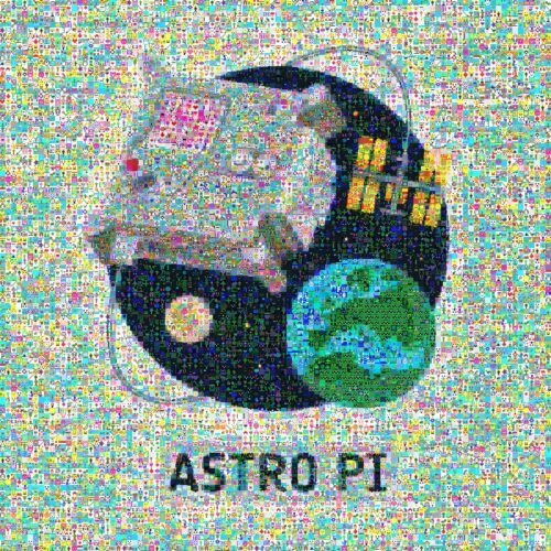
We’re celebrating the many different people involved in this year’s mission with a mosaic of the Mission Zero logo made up of lots of the inspiring designs participants sent us. You can explore an interactive version of the image too!

A mosaic of thousands of designs creating a large version of the Mission Zero logo.
A mosaic of Mission Zero designs

All of the participants whose programs ran on the ISS will be receiving a certificate to recognise their efforts, which will include the time and coordinates of the ISS when their program ran. Programs created by young people from across Europe ran on board the ISS in the final week of May. 

Sign up to the Astro Pi newsletter

If you enjoyed Astro Pi Mission Zero this year, we would be delighted to see you again in the next annual round. If you’re feeling inspired by the images young people have created, we invite you to get involved too. We provide guides and help for all adult mentors who want to support young people to take part, and the step-by-step guide for coding a Mission Zero program in 19 European languages.

Logo of the European Astro Pi Challenge.

The activity of designing an image has been really popular, and we have been super impressed with the creativity of young people’s designs. That’s why we’ll be running Mission Zero in the same format again starting in September.

If you’d like to hear news of the Astro Pi Challenge, please sign up to the newsletter on astro-pi.org: 

We are always interested to hear your feedback about Mission Zero, as a mentor or participant. If you would like to share your thoughts with us, please email [email protected]. 

PS Look out for some cool news about the Astro Pi computers, which we’ll announce soon on this blog!

The post Young people designed 15,000 images for astronauts in Astro Pi Mission Zero 2022/23 appeared first on Raspberry Pi Foundation.

Залезът на българските божества

Post Syndicated from Емилия Милчева original https://www.toest.bg/zalezut-na-bulgarskite-bozhestva/

Залезът на българските божества

Ако следваме Ницше, чукът ще провери божествата „като камертон“, защото при раняването духът нараства. Раните в политиката не са белезите на воина, там всеки пази не духа, а целофана си. Но ударите могат да бъдат разрушителни не с компромати от телефонни разговори, а с документите и фактите, които може да събере една прокуратура.

Без чадър, без целофан

Тъкмо едно от най-големите политически божества започна да се измества от активната политика към мемориала на знаковите политици – и все-още-главният-прокурор Иван Гешев реши да съживи „Барселонагейт“, като поиска имунитета му. Така изпращането на Бойко Борисов трудно ще бъде съпроводено с почести, още по-малко с добри резултати на местните избори.

Заради собствената си кожа Борисов жертва партията си, спечеленото от нея първо място на 2 април, възможното правителство – и това няма да се размине безнаказано. Принуди ГЕРБ да подкрепи не-коалицията с ПП–ДБ. Дори и да изглежда, че част от парламентарната група му е безрезервно вярна, обкръжението му се готви за ГЕРБ след Борисов – време, което приближава по-бързо, отколкото вероятно му се иска на самия лидер. (През 2019 г. „Тоест“ прогнозира, че третият мандат ще е последен.)

Ако доскоро на гърба на Борисов като същински Атлас тежеше партията, днес е новото мнозинство – ГЕРБ–СДС и ПП–ДБ, което в замяна пази парламента от контакт с Иван Гешев и разказа му за доказателства, свързани с къщата в Барселона и златните кюлчета в нощното шкафче. Няколко тома по делото са в деловодството на Народното събрание и любознателни депутати от разни парламентарни групи четат събрания за близо три години доказателствен материал. От една страна, никой не вярва, че прокуратурата може да събере годни за присъда (за пране на пари) доказателства, от друга – може и да са събирали, но главният прокурор да си е мълчал и трупал за „черни дни“, когато проблемът с неговата безконтролност и безнаказаност ще бъде разрешен законодателно.

Български политически стандарт

Балансът в съюза между ГЕРБ–СДС и ПП–ДБ е крехък – правителството на Денков–Габриел зависи от гласовете на депутатите от ГЕРБ–СДС, за да набере мнозинство. Но ако групата на ПП–ДБ може да взаимодейства само с народните представители на Борисов. За тях обаче полигамията в политическите връзки е практика и я доказват общите гласувания с ДПС, „Възраждане“, „Има такъв народ“ – например по промените в Закона за съдебната власт, които извадиха следствието в отделен от прокуратурата орган. Президентът Румен Радев наложи вето на закона и ще е интересно да се види как и дали и този път ще се образува плаващото мнозинство.

Странно е, че в не-коалицията ГЕРБ–СДС могат да възразят по кадрови решения на министри, като например избора за член на борда на Европейската инвестиционна банка на Виолета Лорер, чиято експертност на финансист е безспорна, но в парламента единодействие по законопроекти до момента няма. С изключение на механизма за разследване на главния прокурор, подкрепен от почти всички политически сили без „Възраждане“, и създаването на комисии – за конституционни промени и за имунитетите.

След възраженията от страна на ГЕРБ–СДС за несъгласуваност министърът на финансите Асен Василев съобщи, че Виолета Лорер, съпруга на политика от ПП Даниел Лорер, се е оттеглила от номинацията и вместо нея ще замине друг експерт с опит от Министерството на финансите – Гергана Беремска. Василев обаче беше категоричен, че реакцията срещу Виолета Лорер е била „непремерена“ и „човек, който е поел тежестта да управлява, трябва да има свободата да управлява“. Партньорът на ПП – „Демократична България“, обаче смята, че механизъм за взаимодействие при ключови назначения трябва да има. Макар да предстоят десетки назначения от парламента в ключови регулатори, такъв механизъм все още не е обсъден нито в коалицията ПП–ДБ, нито в не-коалицията им с ГЕРБ.

Напрежението между двете формации се проявява още в първите дни. В резултат Правната комисия на 49-тото НС отхвърли на първо четене законопроектите за реформа на Антикорупционната комисия (КПКОНПИ), внесени от служебното правителство и от депутати от ПП–ДБ. Подкрепен обаче беше проектозаконът на ГЕРБ–СДС и отново пролича, че политическата сила на Борисов е в състояние да си осигури по-широка от официално договорената подкрепа.

За разлика от избирателите на ПП–ДБ, гласоподавателите на ГЕРБ не са притеснени особено от фигурата на олигарха Делян Пеевски. Знаковото му изтикване на преден план от ДПС като виден конституционалист обаче предизвиква разнопосочни коментари както сред електората на ПП–ДБ, така и в самите партии. А гласуването с „въздържал се“ на лидерите на ПП–ДБ по предложението Пеевски да влезе в Конституционната комисия остави чувството за нещо скрито в тесен формат, още повече след като избегнаха публични обяснения за вота си.

Депутатът от ДПС отдавна е политик без целофан, още от протестите през 2013–2014 г., които го осветиха. Но с приобщаването на ДПС към т.нар. конституционно мнозинство той вече е в друга координатна система и ако ползваме Толкин наратива на силите на Промяната – не е от силите на Мрака.

Кой идва след Иван Гешев?

Временно изпълняващият длъжността главен прокурор, който ще бъде избран на мястото на Иван Гешев, на практика може да изкара много дълго време. Може и да има друга гледна точка за имунитетите на Борисов и други депутати. Например че няма да иска снемането им. Но най-напред президентът трябва да подпише указа за освобождаването на Гешев – ако не реши да оспори мотивите за решението на Висшия съдебен съвет.

От ПП–ДБ изразяват публично мнение, че титулярят на поста трябва да бъде избран, след като се извършат промените, свързани със съдебната реформа. Ако тези заявки бъдат изпълнени, временно изпълняващият длъжността обвинител №1 може да се радва на дълголетието на служебната власт, та дори и повече.

Установено е, че институцията главен прокурор в България генерира в себе си много юридическа и фактическа власт. Толкова много, че тя корумпира и значително изкушава лицето, което заема този пост, да прекрачи извън закона установените граници на своето поведение. Това трябва да се реформира на конституционно ниво и чак след това да бъде избран главен прокурор,

заяви по bTV тази седмица депутатката от ПП–ДБ Надежда Йорданова.

Какви са критериите за главния прокурор по закон?

  • Способност за придържане и налагане на висок етичен стандарт.
  • Висока професионална компетентност – да притежава задълбочени знания в областта на правото, богат практически опит в съответната област на правото, ръководни и административни умения, изявени аналитични способности.
  • Изявена независимост, воля за налагане на законността, решителност при изпълнение на служебните задължения и принос за утвърждаването на правовата държава.
  • Да притежава развити умения за работа в екип, за мотивиране на колегите си, за търсене и носене на отговорност.

Също така кандидатът трябва да има най-малко 12 години стаж – зачита се работа като стажант-юрист в Министерството на правосъдието, също и като разследващ полицай с висше юридическо образование в МВР, Министерството на отбраната или разследващ митнически инспектор в Агенция „Митници“. За стаж се признава и опитът на длъжност, за която се изисква висше юридическо образование в институциите, органите и мисиите на ЕС, ООН, ОССЕ, НАТО, както и в международни правораздавателни органи или международни организации, създадени по силата на международен договор, по който Република България е страна.

Докато политическите сили се разберат има или няма сегашният ВСС моралното право да избира новия главен прокурор, да се избира след или преди приключване на съдебната реформа и т.н., ще управлява именно този бъдещ, временно изпълняващ длъжността обвинител.

Да влезе новият добър „Гешев“. Все едно обаче – най-големият политически играч ще трябва да напусне сцената. Божеството се счупи.

Научни новини: Котешки популации, сънят на гълъбите, иновации в трансплантациите и малко AI

Post Syndicated from Михаил Ангелов original https://www.toest.bg/nauchni-novini-koteshki-populacii-sunyat-na-gulubite/

Контрол на котешките популации

Научни новини: Котешки популации, сънят на гълъбите, иновации в трансплантациите и малко AI

Антимюлеровият хормон (АМХ) е важен компонент в развитието на ембрионите при хората. Отделянето му в мъжките зародиши спира развитието на мюлеровите канали в женската репродуктивна система. При мъжете той се отделя от тестисите и нивата му са високи от раждането до началото на пубертета.

При жените е обратно – преди пубертета нивата на хормона са ниски, след това се повишават и започват да спадат бавно до достигане на менопаузата. Отделянето му става в яйчниците, и по-точно от фоликулите, образуващи яйцеклетките. Именно поради това измерването на количеството му е един от най-добрите начини за определяне на яйчниковия резерв – колкото повече от хормона може да се засече, толкова повече фоликули (и съответно потенциални яйцеклетки) са на разположение.

Един от страничните ефекти на химиотерапията е преждевременното изчерпване на яйчниковия резерв – най-вероятно поради повишеното активиране на фоликулите. В проучване върху мишки от 2017 г. учени са проверили ефекта на АМХ при приложението на няколко вещества, използвани в антитуморната терапия.

Резултатите показват категорично, че при умерено увеличаване на нивата на хормона броят на запазените фоликули е значително по-висок (между 1,2 и 2,9 пъти в зависимост от медикамента) при мишките, получавали АМХ, поради по-бавното им развитие. При още по-високи нива на хормона фоликулите в яйчниците се потискат напълно, което на практика води до стерилност на опитните гризачи.

Това лежи в основата на текуща разработка, която с помощта на методите за генна терапия и използването на вирусни вектори може да намери потенциално приложение за намаляване на популациите на бездомните котки. С помощта на аденовирус, използван за вектор, в мускулната тъкан на животните е вмъкнат модифициран ген за котешкия вариант на АМХ. Методът работи сходно на ваксините за COVID-19, използващи аденовируси за вмъкване на спайкпротеините в човешкото тяло с цел обучаване на имунната система и създаване на имунитет – подход, считан за безопасен и приложим в медицината.

Котките са понесли процедурата без забележими странични ефекти върху здравето им и експресията на АМХ е била увеличена. При два последващи 4-месечни периода на съвместно съжителство с мъжки (8 и 20 месеца след третиране) нито една от тях не е забременяла, за разлика от трите контролни котки, включени в изследването.

Според данните концентрацията на АМХ е намаляла с времето, но това не се е отразило на крайния ефект от третирането. В двете години, в които животните са наблюдавани преди публикуването на статията, не е забелязан негативен ефект върху тях. Дори важни хормони като естрогена не са се повлияли от потискането на развитието на фоликулите.

Най-вероятно стопаните на домашни любимци ще продължат да разчитат на хирургичната намеса, защото, освен преките ефекти, кастрацията има и други ползи. Поради хормоналните промени котките спират да се разгонват с всички свързани с това промени в поведението, като силно мяукане, изнервеност и маркиране. Важни положителни последици са също удължаването на живота и намаляването на риска от развиване на рак на млечните жлези и други заболявания.

За уличните котки стратегията може да се окаже изключително успешна, защото дори ефективността на терапията да намалее с времето, с няколко вълни на третиране популацията им може да се намали значително. Това би имало много положителни ефекти както за самите котки, чийто живот не е лек и обикновено е няколко пъти по-кратък от този на домашните, така и за екосистемите.

Котките са изключително ефективни хищници, които нанасят големи щети върху популациите на птиците и малките бозайници. Това, комбинирано с някои зоонотични заболявания, които те пренасят, прави възможността за бърза и лесна кастрация на голям брой котки изключително интересна както за групите за хуманно отношение към животните, така и за държавните институции, отделящи немалки ресурси за справяне с този проблем.

Какво сънуват гълъбите

Сънят е изключително важен процес, който се среща при повечето животни. При хората се наблюдават два типа сън – REM (с бързо движение на очите) и NREM (без бързо движение на очите). По време на първия мозъчната активност е висока и тогава сънуваме най-ярките си сънища, докато при втория активността е намалена и гръбначномозъчната течност (ликвор) циркулира около мозъка – предполага се, че това помага за прочистването му от вредни протеинови отлагания, някои от които свързани с развитието на заболявания като алцхаймер.

С помощта на инфрачервени камери, които следят зениците на птиците, и функционален ЯМР, проследяващ активността на мозъка, немски екип е установил, че при птиците протичат много сходни процеси. По време на REM съня в мозъка на гълъбите, включени в експеримента, са се активирали участъците, отговорни за обработката на визуална информация, включително тази по време на полет. Наред с тях активност е установена и в зоните, приемащи усещането за допир от тялото и крилете. Същото се е случило и в амигдалата, за която се предполага, че както при хората регулира емоциите.

Всичко това кара учените да изкажат хипотезата, че гълъбите имат визуални сънища, в които летят и изпитват емоции. В нейна подкрепа е и наблюдаваното рязко свиване на зениците им, което е характерно и по време на ухажване или при проява на агресия.

Но повишената мозъчна активност по време на REM съня може да има и някои странични ефекти. Невронната плътност при птиците е по-висока, отколкото при бозайниците, поради което почистването на натрупванията по мозъка трябва да е по-често и ефективно, отколкото при бозайниците. По време на REM съня се увеличава притокът на кръв в мозъка, което води до по-интензивно движение на ликвора около него. Изследователите смятат, че в комбинация с по-кратките и по-чести фази на REM сън това най-вероятно помага за премахването на вредни протеини от мозъчните тъкани.

Сигурно видът и съдържанието на сънищата при птиците ще останат ненапълно установени. Но дори горната хипотеза да не се потвърди, изследването дава много информация за съня при нова група животни и помага да се направят паралели между съня при птиците и хората. Това би могло да въведе гълъбите като моделни системи за изследване на процеси, които поради етични или други съображения не могат да се наблюдават при хората.

Иновации в сърдечната трансплантация

Вземането на органи за трансплантация от трупен донор обикновено се извършва по два начина – след мозъчна смърт на донора или след спиране на кръвообращението му. Първият е по-често срещан, защото въпреки загубата на мозъчна функция физиологичните процеси в тялото се поддържат и органите се запазват жизнени и в естествено състояние до момента на трансплантация. При спиране на кръвообращението настъпват редица усложнения, тъй като органите и тъканите не получават кислород, вследствие на което започват да се увреждат и сравнително бързо стават негодни за трансплантиране.

Поради това броят на такива операции все още е сравнително малък въпреки общия недостиг на донори. С напредването на медицинските технологии броят на органите, които могат да се използват след спиране на кръвообращението, нараства и прогнозата за успешна трансплантация се увеличава, като процедурата вече се прилага за пациенти с нужда от бъбреци и черен дроб. Доскоро това беше изключително трудно при сърцето, поради което се вземаха органи от донори само след мозъчна смърт.

Възможност за увеличаване на броя на потенциалните донори предлага използването на машина, която поддържа циркулацията и електрическите импулси в експлантираното сърце, т.нар. сърце в кутия. Това е сравнително нова технология и все още се прилага в малко клиники – донякъде защото доскоро нямаше данни за състоянието на пациентите, преминали през трансплантация на такива органи.

След публикуването на изследване, включващо 180 души, разделени на две групи (едните, получили орган от донор в мозъчна смърт, a другите – от донор след спиране на кръвообращението му), вече е известно, че почти няма разлика в успеваемостта на процедурата 6 месеца след провеждането ѝ. При първия подход, който се смята за рутинен, процентът живи реципиенти е бил 90, а при втория – 94. Не е имало съществена разлика и в развитието на сериозни странични ефекти 30 дни след трансплантацията и при двата типа процедури. Според авторите на изследването данните са достатъчно убедителни за внедряване на подхода в повече болнични заведения.

Тази техника ще е полезна и при по-често срещани трансплантации след мозъчна смърт. Традиционната практика е след експлантиране на органа той да бъде поставен в лед за транспорт. Това дава на екипа около 4 часа да стигне до реципиента, което ограничава разстоянието за получаване на органа. Ако сърцето е поставено в машината, то може да бъде поддържано по-дълго време и съответно да пътува по-далеч. Наред с това лекарите имат възможност да проверят дали органът функционира нормално, или има увреждания, преди той да бъде имплантиран, което повишава шанса за успешно протичане на процедурата.

Подобрен от AI алгоритъм за сортиране

Сортирането е важен процес в компютърните технологии, който намира най-различни приложения. Затова разработката и оптимизацията на алгоритмите, с които се извършва, е поле на активна изследователска дейност. Една от задачите е сортирането на малки набори, което от своя страна е част от алгоритмите, използващи разделяне на по-големите набори и сортиране „на порции“.

Въпреки че решенията, използвани в момента, са плод на дългогодишен труд, има възможност за подобрение. Нова разработка на подразделението на Google – DeepMind, успешно е оптимизирала алгоритми за сортиране, разработени от хора, като в някои случаи използваният подход е бил „неинтуитивен“ – с други думи, не е нещо, което би дошло на ум на човек.

AlphaDev е изкуствен интелект, базиран на шампиона по играта „го“ на DeepMind – AlphaZero. Използваният подход за обучение е с утвърждаване (reinforcement learning). При него програмата не получава предварителни знания, а с помощта на многократни итерации върху задачата и посочени награди и наказания тя намира най-подходящия начин за постигане на най-висок резултат, подобно на видеоигра. Именно такава дефиниция използват от компанията – игра на асемблер (най-базовия човешко четим език за програмиране). В нея резултатът се определя от времето за изпълнение на алгоритъма за сортиране – колкото по-кратко е то, толкова по-висок е резултатът.

След задаване на правилата AlphaDev започва своеобразна игра, променяйки части от алгоритъма за сортиране. При всяка промяна се отчита времето за изпълнение и дали полученият резултат отговаря на очаквания – ако се подадат числа в случаен ред, те трябва да бъдат подредени след сортирането. Всеки „рунд“ се оценява и сравнява с предишния, което определя дали ще бъде използван за основа на следващия, или ще бъде отхвърлен. В случая откритата оптимизация е възможността за премахване на една стъпка в алгоритъма за сортиране, което ускорява процедурата с до 70% при боравене с 5 елемента и с около 1,7% при над 250 000.

Според авторите подобни алгоритми се изпълняват трилиарди пъти всеки ден, поради което дори и най-малкото забързване ще допринесе за много спестено процесорно време. Разработката на AlphaDev е публикувана в журнала Nature, а оптимизираният алгоритъм вече е прехвърлен в стандартната C++ библиотека за сортиране и всички програмисти имат свободен достъп до него.

Интересен коментар за тази оптимизация дава потребителят Dimitris Papailiopoulos в Twitter. С две запитвания към GPT-4 той постига същия резултат без необходимостта от отнемащото време и ресурси обучение с утвърждаване. Донякъде задачата му е улеснена, защото вече има насока за начина на подобряване на алгоритъма, но все пак е показателно за напредналото ниво на технологията на OpenAI и потенциала, който крие. Възможност за бъдещи подобрения предоставя използването на изкуствен интелект, сходен на AlphaDev – така може да се откриват иновативни подходи, които не биха хрумнали на човек, а след това те да бъдат оптимизирани с помощта на GPT-4 или следващите му версии.

Заглавно изображение: Микроскопска снимка на стъбло на едногодишен бор, напречен разрез, 100х увеличение. Източник: BCC Bioscience Image Library, CC0 / Flickr

Deploying an automated Amazon CloudWatch dashboard for AWS Outposts using AWS CDK

Post Syndicated from Sheila Busser original https://aws.amazon.com/blogs/compute/deploying-an-automated-amazon-cloudwatch-dashboard-for-aws-outposts-using-aws-cdk/

This post is written by Enrico Liguori, Networking Solutions Architect, Hybrid Cloud and Sumeeth Siriyur, Sr. Hybrid Cloud Solutions Architect.

AWS Outposts is a fully managed service that brings the same AWS infrastructure, services, APIs, and tools to virtually any data center, colocation space, manufacturing floor, or on-premises facility where it might be needed. With Outposts, you can run some AWS services on-premises and connect to a broad range of services available in the local AWS Region. Outposts supports workloads requiring low latency, local data processing, data residency, and application migration.

Outposts capacity is driven as per your compute and storage requirements to run workloads. You can monitor Outposts resources using metrics gathered by Amazon CloudWatch. Using these metrics, you can effectively monitor and manage the Outposts resources as they would in the Region, levereging cloud native tools such as CloudWatch dashboards. Check the Monitoring best practices for AWS Outposts blog post to dive deep into the available monitoring options for Outposts.

CloudWatch dashboards are customizable home pages in the CloudWatch console that can be used to monitor resources running on Outposts in a single view. For example, you can monitor in a single pane the number Amazon EC2 instances used per EC2 instance type, the available capacity of Amazon EBS volumes and Amazon S3 buckets, and the operational status of the service link of Outposts.

As a you start deploying additional Outposts resources as a part of their capacity expansion, they must all be integrated and visualized within CloudWatch in an automated way. Traditionally CloudWatch dashboards are built manually and may be time consuming to tune. This post provides also an overview of building CloudWatch dashboards in an automated way using AWS Cloud Development Kit (AWS CDK).

Overview

CloudWatch metrics available to monitor Outposts resources and capacity

CloudWatch metrics for Outposts are available to customers in all public AWS Regions and AWS GovCloud (US) at no additional cost. We can classify the available metrics in two main categories:

To identify the metrics published under the service specific namespaces, we can leverage metadata in the form of tags. A tag is a label that you assign to an AWS resource and consists of a key and an optional value. For the purpose of the monitoring strategy described in this post, we use a tag that contains the OutpostID of the Outpost where the resource is deployed. In this way, we can easily filter the CloudWatch metrics that we would like to show in our dashboard.

To enforce the assignment of tags to our resources we can implement a tagging strategy using AWS tag Policies and Service Control Policies (SCPs).

The following sections describe two different methods to build a CloudWatch dashboard that includes the different types of metrics described so far. In both cases, we see how particularly useful the presence of tags is to identify the service-specific metrics.

Manual approach to building a CloudWatch dashboard for Outposts

This section describes a manual (i.e., non-automated) approach to building a dashboard that could summarize both the capacity utilization metrics and the service specific metrics for your resources running on Outposts.

The benefit of this approach is that we can implement a fully operational dashboard directly from the CloudWatch console. However, it will simultaneously require more effort to properly tune the dashboard to satisfy your monitoring requirements.

You can start creating the dashboard opening the CloudWatch console and following the steps listed in the public documentation.

To display a metric under AWS/Outposts namespace we can choose any of the widgets available. Based on the nature of the data, we can choose different types of Widgets such as Number, Line, Gauge, Explorer, or you can even build your own custom widget.

Together with the Widget type, we must select Outposts namespace in the metric graph dialog box and then navigate to the specific metric of interest.

In case we are creating the dashboard in a different account than the Outposts owner, we must select the right account in the View data drop-down menu to see the Outposts metric in which we are interested.

View data drop-down menu

After selecting one or more metrics we can select Create widget button.

For the service specific metrics, we recommend using the explorer widget. In this way, we can utilize the tagging strategy described earlier to automatically identify the metrics belonging to the resources running on Outposts. Check the documentation page for a step-by-step guide for creating an explorer widget based on tags.

Automated outpost dashboard

After we’ve seen how to build a dashboard manually from the console, in this secton we describe an automated approach to deploy a dashboard for Outposts through AWS CDK.

AWS CDK is an open source software development framework to model and provision your cloud application resources using familiar programming languages, including TypeScript, JavaScript, Python, C#, and Java. For the solution in this post, we use Python.

Architecture overview

The AWS CDK stack described in this post, assumes that the resources running on Outposts (EC2 instances, S3 buckets, Application Load Balancers (ALBs), and RDS instances) are tagged using the tagging strategy described earlier.

Specifying a tag name and a tag value in a configuration file automatically discovers the resources with that tag and adds the related metrics to the CloudWatch dashboard.

Together with the service specific metrics, it creates a series of widgets that we can use to monitor the capacity available and utilized in each Outpost that belongs to the account where the script is running.

The workflow is made of the following phases:

  1. The AWS CDK stack creates an AWS CodeCommit repository and uploads its own code into it. The code contains a series of modules, one for each section of the CloudWatch dashboard. A section of the dashboard contains one or more widgets showing the metrics of a specific service.
  2. To maintain the CloudWatch dashboard always up-to-date with the resources matching the tag, it creates a pipeline in AWS CodePipeline that can dynamically create and or update the dashboard. The pipeline runs the code in the CodeCommit repository and is made of two stages. In the first one, the build stage, it builds the dependencies needed by the AWS CDK stack. In the second stage, the Deploy stage, it loads and runs the modules used to build the dashboard.
  3. Each module contains the code to automatically discover the tagged resources of a specific service. This discovery phase uses standard AWS APIs called through the Python SDK Boto3.
  4. Based on the results of the discovery phase, AWS CDK produces an AWS CloudFormation template containing the definition of the CloudWatch dashboard sections. The template is submitted to CloudFormation.
  5. CloudFormation creates or, if already defined, updates the CloudWatch dashboard.
  6. Together with the dashboard, the AWS CDK script also contains the definition of a CloudWatch Event that, once deployed, triggers the pipeline each time a resource tagged with the specified tag is created or destroyed.

Prerequisites

To implement the solution presented in this post, you must configure:

  1. git as distributed version control system.
  2. In case it is the first time that you’re using AWS CDK in this account and region, you must:

a. Install the AWS CDK, and its prerequisites, following these instructions.

b. Go through the AWS CDK bootstrapping process. This is required only for the first time that we use AWS CDK in a specific AWS environment (an AWS environment is a combination of an AWS account and Region).

How to install

Step 1: Clone the AWS CDK code hosted on GitHub with:

$ git clone https://github.com/aws-samples/automated-cloudwatch-dashboard.git

Step 2: enter the directory using the following:

$ cd  automated-cloudwatch-dashboard/

Step 3: Install the needed Python dependencies with:

$ pip install -r requirements.txt

Step 4: Modify the configuration file

Before deploying the stack, we must modify the configuration file to specify the tag we use for identifying our resources running on Outposts. Open the file with the name config.yaml with your preferred text editor and specify:

      • A name for the dashboard. The default name used is Automated-CloudWatch-Dashboard.
      • Replace <tag_name> placeholder following the tag_name variable with the tag name used to tag the resources that you want to include in the dashboard.
      • Replace <tag_value> placeholder under tag_values variable with the tag value that you used.

Here is an example config.yaml configuration file:

dashboard_name: Automated-CloudWatch-Dahsboard
tag_name: OutpostID
tag_values:
  - op-1234567890abcdefg 

Stack deployment

We can deploy the stack with the following:

$ cdk deploy

At the end of the deployment process, the pipeline that creates the dashboard is provisioned. You can now go to your CloudWatch console to view it.

Automated Outposts dashboard overview

Now that we have built our dashboard, let’s review each section:

  1. Outpost capacity

Outpost Capacity diagram

The AWS CDK stacks define a capacity section for each Outpost available to the AWS account where the script runs.

In this section, we find four widgets showing metrics published under the AWS/Outpost namespace. The first widget shows for each EC2 instance type available on the Outposts the number of instances utilized and available for that instance type. In the second row, we can visualize the available capacity for the Amazon EBS volumes and for the S3 buckets. The last widget shows the operational status of the service link of Outposts.

2. EC2 instances

CPU, Network, and Disk Utilization for an EC2 instance diagram

In this section of the dashboard, we find the metrics showing the CPU, Network, and Disk Utilization for an EC2 instance. It has defined a section of this type for each EC2 instance with a tag assigned matching the name and the value specified in the configuration file of the script.

3. Application Load Balancer

The ALB section aggregates metrics showing the operational status of a load balancer hosted on Outposts

The ALB section aggregates metrics showing the operational status of a load balancer hosted on Outposts. A section of this type is defined for each ALB with an assigned tag matching the one specified in the configuration file.

4. S3 buckets

The S3 buckets section diagram

The S3 buckets section is defined only once and aggregates the utilization metrics for all S3 buckets with an assigned tag.

5. AutoScaling group

The AutoScaling group section diagram

The AutoScaling group section can be used to monitor the number of instances in service in a specific AS group with a tag assigned. This section is defined once and can aggregate the metrics for multiple AutoScaling groups.

Clean up

To terminate the resources that we created in this post, run the following:

$ cdk destroy

Then, go to the Cloudformation console and delete the stack with the name “Deploy-AutomatedCloudWatchDashboard”.

Conclusion

In conclusion, this post demonstrates a manual way of creating CloudWatch Metrics dashboard using the CloudWatch console and an automated way using AWS CDK. The automated approach is also scalable by automatically discovering any new resources added to the existing Outposts in the your environment without any changes to the code.

HPE ProLiant RL300 Gen11 Review A Leadership Ampere Altra Max Arm Server

Post Syndicated from Patrick Kennedy original https://www.servethehome.com/hpe-proliant-rl300-gen11-review-an-ampere-altra-max-arm-server/

The HPE ProLiant RL300 Gen11 is a new leadership cloud-native Ampere Altra Max Arm platform bringing 128 Arm cores to the ProLiant ecosystem

The post HPE ProLiant RL300 Gen11 Review A Leadership Ampere Altra Max Arm Server appeared first on ServeTheHome.

Improved resiliency with backpressure and admission control for Amazon OpenSearch Service

Post Syndicated from Ketan Verma original https://aws.amazon.com/blogs/big-data/improved-resiliency-with-backpressure-and-admission-control-for-amazon-opensearch-service/

Amazon OpenSearch Service is a managed service that makes it simple to secure, deploy, and operate OpenSearch clusters at scale in the AWS Cloud. Last year, we introduced Shard Indexing Backpressure and admission control, which monitors cluster resources and incoming traffic to selectively reject requests that would otherwise pose stability risks like out of memory and impact cluster performance due to memory contentions, CPU saturation and GC overhead, and more.

We are now excited to introduce Search Backpressure and CPU-based admission control for OpenSearch Service, which further enhances the resiliency of clusters. These improvements are available for all OpenSearch versions 1.3 or higher.

Search Backpressure

Backpressure prevents a system from being overwhelmed with work. It does so by controlling the traffic rate or by shedding excessive load in order to prevent crashes and data loss, improve performance, and avoid total failure of the system.

Search Backpressure is a mechanism to identify and cancel in-flight resource-intensive search requests when a node is under duress. It’s effective against search workloads with anomalously high resource usage (such as complex queries, slow queries, many hits, or heavy aggregations), which could otherwise cause node crashes and impact the cluster’s health.

Search Backpressure is built on top of the task resource tracking framework, which provides an easy-to-use API to monitor each task’s resource usage. Search Backpressure uses a background thread that periodically measures the node’s resource usage and assigns a cancellation score to each in-flight search task based on factors like CPU time, heap allocations, and elapsed time. A higher cancellation score corresponds to a more resource-intensive search request. Search requests are cancelled in descending order of their cancellation score to recover nodes quickly, but the number of cancellations is rate-limited to avoid wasteful work.

The following diagram illustrates the Search Backpressure workflow.

Search requests return an HTTP 429 “Too Many Requests” status code upon cancellation. OpenSearch returns partial results if only some shards fail and partial results are allowed. See the following code:

{
    "error": {
        "root_cause": [
            {
                "type": "task_cancelled_exception",
                "reason": "cancelled task with reason: heap usage exceeded [403mb >= 77.6mb], elapsed time exceeded [1.7m >= 45s]"
            }
        ],
        "type": "search_phase_execution_exception",
        "reason": "SearchTask was cancelled",
        "phase": "fetch",
        "grouped": true,
        "failed_shards": [
            {
                "shard": 0,
                "index": "nyc_taxis",
                "node": "9gB3PDp6Speu61KvOheDXA",
                "reason": {
                    "type": "task_cancelled_exception",
                    "reason": "cancelled task with reason: heap usage exceeded [403mb >= 77.6mb], elapsed time exceeded [1.7m >= 45s]"
                }
            }
        ],
        "caused_by": {
            "type": "task_cancelled_exception",
            "reason": "cancelled task with reason: heap usage exceeded [403mb >= 77.6mb], elapsed time exceeded [1.7m >= 45s]"
        }
    },
    "status": 429
}

Monitoring Search Backpressure

You can monitor the detailed Search Backpressure state using the node stats API:

curl -X GET "https://{endpoint}/_nodes/stats/search_backpressure"

You can also view the cluster-wide summary of cancellations using Amazon CloudWatch. The following metrics are now available in the ES/OpenSearchService namespace:

  • SearchTaskCancelled – The number of coordinator node cancellations
  • SearchShardTaskCancelled – The number of data node cancellations

The following screenshot shows an example of tracking these metrics on the CloudWatch console.

CPU-based admission control

Admission control is a gatekeeping mechanism that proactively limits the number of requests to a node based on its current capacity, both for organic increases and spikes in traffic.

In addition to the JVM memory pressure and request size thresholds, it now also monitors each node’s rolling average CPU usage to reject incoming _search and _bulk requests. It prevents nodes from being overwhelmed with too many requests leading to hot spots, performance problems, request timeouts, and other cascading failures. Excessive requests return an HTTP 429 “Too Many Requests” status code upon rejection.

Handling HTTP 429 errors

You’ll receive HTTP 429 errors if you send excessive traffic to a node. It indicates either insufficient cluster resources, resource-intensive search requests, or an unintended spike in the workload.

Search Backpressure provides the reason for rejection, which can help fine-tune resource-intensive search requests. For traffic spikes, we recommend client-side retries with exponential backoff and jitter.

You can also follow these troubleshooting guides to debug excessive rejections:

Conclusion

Search Backpressure is a reactive mechanism to shed excessive load, while admission control is a proactive mechanism to limit the number of requests to a node beyond its capacity. Both work in tandem to improve the overall resiliency of an OpenSearch cluster.

Search Backpressure is available in OpenSearch, and we are always looking for external contributions. You can refer to the RFC to get started.


About the authors

Ketan Verma is a Senior SDE working on Amazon OpenSearch Service. He is passionate about building large-scale distributed systems, improving performance, and simplifying complex ideas with simple abstractions. Outside work, he likes to read and improve his home barista skills.

Suresh N S is a Senior SDE working on Amazon OpenSearch Service. He is passionate towards solving problems in large scale distributed systems.

Pritkumar Ladani is an SDE-2 working on Amazon OpenSearch Service. He likes to contribute to open source software development, and is passionate about distributed systems. He is an amateur badminton player and enjoys trekking.

Bukhtawar Khan is a Principal Engineer working on Amazon OpenSearch Service. He is interested in building distributed and autonomous systems. He is a maintainer and an active contributor to OpenSearch.

Secure Connectivity from Public to Private: Introducing EC2 Instance Connect Endpoint

Post Syndicated from Sheila Busser original https://aws.amazon.com/blogs/compute/secure-connectivity-from-public-to-private-introducing-ec2-instance-connect-endpoint-june-13-2023/

This blog post is written by Ariana Rahgozar, Solutions Architect, and Kenneth Kitts, Sr. Technical Account Manager, AWS.

Imagine trying to connect to an Amazon Elastic Compute Cloud (Amazon EC2) instance within your Amazon Virtual Private Cloud (Amazon VPC) over the Internet. Typically, you’d first have to connect to a bastion host with a public IP address that your administrator set up over an Internet Gateway (IGW) in your VPC, and then use port forwarding to reach your destination.

Today we launched Amazon EC2 Instance Connect (EIC) Endpoint, a new feature that allows you to connect securely to your instances and other VPC resources from the Internet. With EIC Endpoint, you no longer need an IGW in your VPC, a public IP address on your resource, a bastion host, or any agent to connect to your resources. EIC Endpoint combines identity-based and network-based access controls, providing the isolation, control, and logging needed to meet your organization’s security requirements. As a bonus, your organization administrator is also relieved of the operational overhead of maintaining and patching bastion hosts for connectivity. EIC Endpoint works with the AWS Management Console and AWS Command Line Interface (AWS CLI). Furthermore, it gives you the flexibility to continue using your favorite tools, such as PuTTY and OpenSSH.

In this post, we provide an overview of how the EIC Endpoint works and its security controls, guide you through your first EIC Endpoint creation, and demonstrate how to SSH to an instance from the Internet over the EIC Endpoint.

EIC Endpoint product overview

EIC Endpoint is an identity-aware TCP proxy. It has two modes: first, AWS CLI client is used to create a secure, WebSocket tunnel from your workstation to the endpoint with your AWS Identity and Access Management (IAM) credentials. Once you’ve established a tunnel, you point your preferred client at your loopback address (127.0.0.1 or localhost) and connect as usual. Second, when not using the AWS CLI, the Console gives you secure and seamless access to resources inside your VPC. Authentication and authorization is evaluated before traffic reaches the VPC. The following figure shows an illustration of a user connecting via an EIC Endpoint:

Figure 1 shows a user connecting to private EC2 instances within a VPC through an EIC Endpoint

Figure 1. User connecting to private EC2 instances through an EIC Endpoint

EIC Endpoints provide a high degree of flexibility. First, they don’t require your VPC to have direct Internet connectivity using an IGW or NAT Gateway. Second, no agent is needed on the resource you wish to connect to, allowing for easy remote administration of resources which may not support agents, like third-party appliances. Third, they preserve existing workflows, enabling you to continue using your preferred client software on your local workstation to connect and manage your resources. And finally, IAM and Security Groups can be used to control access, which we discuss in more detail in the next section.

Prior to the launch of EIC Endpoints, AWS offered two key services to help manage access from public address space into a VPC more carefully. First is EC2 Instance Connect, which provides a mechanism that uses IAM credentials to push ephemeral SSH keys to an instance, making long-lived keys unnecessary. However, until now EC2 Instance Connect required a public IP address on your instance when connecting over the Internet. With this launch, you can use EC2 Instance Connect with EIC Endpoints, combining the two capabilities to give you ephemeral-key-based SSH to your instances without exposure to the public Internet. As an alternative to EC2 Instance Connect and EIC Endpoint based connectivity, AWS also offers Systems Manager Session Manager (SSM), which provides agent-based connectivity to instances. SSM uses IAM for authentication and authorization, and is ideal for environments where an agent can be configured to run.

Given that EIC Endpoint enables access to private resources from public IP space, let’s review the security controls and capabilities in more detail before discussing creating your first EIC Endpoint.

Security capabilities and controls

Many AWS customers remotely managing resources inside their VPCs from the Internet still use either public IP addresses on the relevant resources, or at best a bastion host approach combined with long-lived SSH keys. Using public IPs can be locked down somewhat using IGW routes and/or security groups. However, in a dynamic environment those controls can be hard to manage. As a result, careful management of long-lived SSH keys remains the only layer of defense, which isn’t great since we all know that these controls sometimes fail, and so defense-in-depth is important. Although bastion hosts can help, they increase the operational overhead of managing, patching, and maintaining infrastructure significantly.

IAM authorization is required to create the EIC Endpoint and also to establish a connection via the endpoint’s secure tunneling technology. Along with identity-based access controls governing who, how, when, and how long users can connect, more traditional network access controls like security groups can also be used. Security groups associated with your VPC resources can be used to grant/deny access. Whether it’s IAM policies or security groups, the default behavior is to deny traffic unless it is explicitly allowed.

EIC Endpoint meets important security requirements in terms of separation of privileges for the control plane and data plane. An administrator with full EC2 IAM privileges can create and control EIC Endpoints (the control plane). However, they cannot use those endpoints without also having EC2 Instance Connect IAM privileges (the data plane). Conversely, DevOps engineers who may need to use EIC Endpoint to tunnel into VPC resources do not require control-plane privileges to do so. In all cases, IAM principals using an EIC Endpoint must be part of the same AWS account (either directly or by cross-account role assumption). Security administrators and auditors have a centralized view of endpoint activity as all API calls for configuring and connecting via the EIC Endpoint API are recorded in AWS CloudTrail. Records of data-plane connections include the IAM principal making the request, their source IP address, the requested destination IP address, and the destination port. See the following figure for an example CloudTrail entry.

Figure 2 shows a sample cloud trail entry for SSH data-plane connection for an IAMUser. Specific entry:  Figure 2. Partial CloudTrail entry for an SSH data-plane connection

EIC Endpoint supports the optional use of Client IP Preservation (a.k.a Source IP Preservation), which is an important security consideration for certain organizations. For example, suppose the resource you are connecting to has network access controls that are scoped to your specific public IP address, or your instance access logs must contain the client’s “true” IP address. Although you may choose to enable this feature when you create an endpoint, the default setting is off. When off, connections proxied through the endpoint use the endpoint’s private IP address in the network packets’ source IP field. This default behavior allows connections proxied through the endpoint to reach as far as your route tables permit. Remember, no matter how you configure this setting, CloudTrail records the client’s true IP address.

EIC Endpoints strengthen security by combining identity-based authentication and authorization with traditional network-perimeter controls and provides for fine-grained access control, logging, monitoring, and more defense in depth. Moreover, it does all this without requiring Internet-enabling infrastructure in your VPC, minimizing the possibility of unintended access to private VPC resources.

Getting started

Creating your EIC Endpoint

Only one endpoint is required per VPC. To create or modify an endpoint and connect to a resource, a user must have the required IAM permissions, and any security groups associated with your VPC resources must have a rule to allow connectivity. Refer to the following resources for more details on configuring security groups and sample IAM permissions.

The AWS CLI or Console can be used to create an EIC Endpoint, and we demonstrate the AWS CLI in the following. To create an EIC Endpoint using the Console, refer to the documentation.

Creating an EIC Endpoint with the AWS CLI

To create an EIC Endpoint with the AWS CLI, run the following command, replacing [SUBNET] with your subnet ID and [SG-ID] with your security group ID:

aws ec2 create-instance-connect-endpoint \
    --subnet-id [SUBNET] \
    --security-group-id [SG-ID]

After creating an EIC Endpoint using the AWS CLI or Console, and granting the user IAM permission to create a tunnel, a connection can be established. Now we discuss how to connect to Linux instances using SSH. However, note that you can also use the OpenTunnel API to connect to instances via RDP.

Connecting to your Linux Instance using SSH

With your EIC Endpoint set up in your VPC subnet, you can connect using SSH. Traditionally, access to an EC2 instance using SSH was controlled by key pairs and network access controls. With EIC Endpoint, an additional layer of control is enabled through IAM policy, leading to an enhanced security posture for remote access. We describe two methods to connect via SSH in the following.

One-click command

To further reduce the operational burden of creating and rotating SSH keys, you can use the new ec2-instance-connect ssh command from the AWS CLI. With this new command, we generate ephemeral keys for you to connect to your instance. Note that this command requires use of the OpenSSH client. To use this command and connect, you need IAM permissions as detailed here.

Once configured, you can connect using the new AWS CLI command, shown in the following figure:
Figure 3 shows the AWS CLI view if successfully connecting to your instance using the one-click command. When running the command, you are prompted to connect and can access your instance.

Figure 3. AWS CLI view upon successful SSH connection to your instance

To test connecting to your instance from the AWS CLI, you can run the following command where [INSTANCE] is the instance ID of your EC2 instance:

aws ec2-instance-connect ssh --instance-id [INSTANCE]

Note that you can still use long-lived SSH credentials to connect if you must maintain existing workflows, which we will show in the following. However, note that dynamic, frequently rotated credentials are generally safer.

Open-tunnel command

You can also connect using SSH with standard tooling or using the proxy command. To establish a private tunnel (TCP proxy) to the instance, you must run one AWS CLI command, which you can see in the following figure:

Figure 4 shows the AWS CLI view after running the aws ec2-instance-connect open-tunnel command and connecting to your instance.Figure 4. AWS CLI view after running new SSH open-tunnel command, creating a private tunnel to connect to our EC2 instance

You can run the following command to test connectivity, where [INSTANCE] is the instance ID of your EC2 instance and [SSH-KEY] is the location and name of your SSH key. For guidance on the use of SSH keys, refer to our documentation on Amazon EC2 key pairs and Linux instances.

ssh ec2-user@[INSTANCE] \
    -i [SSH-KEY] \
    -o ProxyCommand='aws ec2-instance-connect open-tunnel \
    --instance-id %h'

Once we have our EIC Endpoint configured, we can SSH into our EC2 instances without a public IP or IGW using the AWS CLI.

Conclusion

EIC Endpoint provides a secure solution to connect to your instances via SSH or RDP in private subnets without IGWs, public IPs, agents, and bastion hosts. By configuring an EIC Endpoint for your VPC, you can securely connect using your existing client tools or the Console/AWS CLI. To learn more, visit the EIC Endpoint documentation.

CVE-2023-34362: MOVEit Vulnerability Timeline of Events

Post Syndicated from Rapid7 original https://blog.rapid7.com/2023/06/14/etr-cve-2023-34362-moveit-vulnerability-timeline-of-events/

CVE-2023-34362: MOVEit Vulnerability Timeline of Events

The following article was written by Drew Burton and Cynthia Wyre.

Rapid7 continues to track the impact of CVE-2023-34362, a critical zero-day vulnerability in Progress Software’s MOVEit Transfer solution. CVE-2023-34362 allows for SQL injection, which can result in unauthorized access to sensitive data, such as passwords, credit card details, or personal user information.

Rapid7 is not currently seeing evidence that commodity or low-skill attackers are exploiting the vulnerability. However, the exploitation of available high-value targets globally across a wide range of org sizes, verticals, and geo-locations indicates that this is a widespread threat. We expect to see a longer list of victims come out as time goes on.

We’ve put together a timeline of events to date for your reference.

MOVEit Timeline

May 27-28: Rapid7 services teams have so far confirmed indicators of compromise and data exfiltration dating back to at least May 27 and May 28, 2023 (respectively).

May 31: Progress Software publishes an advisory on a critical SQL injection vulnerability in their MOVEit Transfer solution.

May 31: Rapid7 begins investigating exploitation of MOVEit Transfer.

June 1: Rapid7 publishes initial analysis of MOVEit Transfer attacks after responding to incidents across multiple customer environments.

June 1: The security community publishes technical details and indicators of compromise.

June 1: Compromises continue; Rapid7 responds to alerts.

June 1: CISA publishes Security Advisory.

June 2: CVE-2023-34362 is assigned to the zero-day vulnerability.

June 2: Mandiant attributes the attack to a threat cluster with unknown motives.

June 2: Velociraptor releases an artifact to detect exploitation of MOVEit File Transfer critical vulnerability.

June 4: Rapid7 publishes a method to identify which data was stolen.

June 4: Nova Scotian government discloses it is investigating privacy breach.

June 5: Microsoft attributes the attack to Lace Tempest, a Cl0p ransomware affiliate that has previously exploited vulnerabilities in other file transfer solutions (e.g., Accellion FTA, Fortra GoAnywhere MFT).

June 5: UK companies BA, BBC, and Boots disclose breaches as victims in MOVEit File Transfer.

June 5: Cl0p ransomware group claims responsibility for the zero-day attack.

June 6: Security firm Huntress releases a video allegedly reproducing the exploit chain.

June 6: The Cl0p ransomware group posts a communication on their leak site demanding that victim organizations contact them by June 14 to negotiate extortion fees in exchange for the deletion of stolen data.

June 7: CISA publishes #StopRansomware Cybersecurity Advisory regarding MOVEit File Transfer Vulnerability CVE-2023-34362.

June 9: Progress Software updates advisory to include a patch for a second MOVEit Transfer Vulnerability, which was uncovered by Huntress during a third-party code review. The vulnerability is later assigned CVE-2023-35036.

June 12: Rapid7 releases a full exploit chain for MOVEit Transfer Vulnerability CVE-2023-34362.

Mitigation

All MOVEit Transfer versions before May 31, 2023 are vulnerable to CVE-2023-34362, and all MOVEit Transfer versions before June 9, 2023 are vulnerable to CVE-2023-35036. As noted above, fixed versions of the software are available, and patches should be applied on an emergency basis.

Patches are available via Progress Software’s CVE-2023-34362 advisory. Additionally, because CVE-2023-34362 is a zero-day vulnerability, Progress Software is advising MOVEit Transfer and MOVEit Cloud customers to check for indicators of unauthorized access over “at least the past 30 days.”

According to the company’s status page, Progress also took the following steps aimed at increasing security monitoring and defending against further exploitation or attack:

  • Developed specific monitoring signatures on Progress’ endpoint protection system.
  • Validated that the newly developed patch corrected the vulnerability.
  • Tested detection rules before finalizing to ensure that notifications are working properly.
  • Engaged outside cybersecurity experts and other incident response professionals to conduct a forensic investigation and assess the extent and scope of the incident.

As noted in the timeline above, Rapid7 has added capabilities across our portfolio that can help users identify and resolve risk from CVE-2023-34362. We have also identified a method to identify exfiltrated data from compromised MOVEit customer environments.

To learn more, check out: Rapid7 Observed Exploitation of Critical MOVEit Transfer Vulnerability

GitHub Availability Report: May 2023

Post Syndicated from Jakub Oleksy original https://github.blog/2023-06-14-github-availability-report-may-2023/

In May, we experienced four incidents that resulted in degraded performance across GitHub services. This report also sheds light into three April incidents that resulted in degraded performance across GitHub services.

April 26 23:11 UTC (lasting 51 minutes)

On April 25 at 23:11 UTC, a subset of users began to see a degraded experience with GitHub Copilot code completions. We publicly statused GitHub Copilot to yellow at 23:26 UTC, and to red at 23:41 UTC. As engineers identified the impact to be a subset of requests, we statused back to yellow at 23:48 UTC. The incident was fully resolved on April 26 at 00:02 UTC, and we publicly statused green at 00:30 UTC.

The degradation consisted of a rolling partial outage across all three GitHub Copilot regions: US Central, US East, and Switzerland North. Each of these regions experienced approximately 15-20 minutes of degraded service during the global incident. At the peak, 6% of GitHub Copilot code completion requests failed.

We identified the root cause to be a faulty configuration change by an automated maintenance process. The process was initiated across all regions sequentially, and placed a subset of faulty nodes in service before the rollout was halted by operators. Automated traffic rollover from the failed nodes and regions helped to mitigate the issue.

Our efforts to prevent a similar incident in the future include both reducing the batch size and iteration speed of the automated maintenance process, and lowering our time to detection by adjusting our alerting thresholds.

April 27 08:59 UTC (lasting 57 minutes)

On April 26 at 08:59 UTC, our internal monitors notified us of degraded availability with GitHub Packages. Users would have noticed slow or failed GitHub Packages upload and download requests. Our investigation revealed a spike in connection errors to our primary database node. We quickly took action to resolve the issue by manually restarting the database. At 09:56 UTC, all errors were cleared and users experienced a complete recovery of the GitHub Packages service. A planned migration of GitHub Packages database to a more robust platform was completed on May 2, 2023 to prevent this issue from recurring.

April 28 12:26 UTC (lasting 19 minutes)

On April 28 at 12:26 UTC, we were notified of degraded availability for GitHub Codespaces. Users in the East US region experienced failures when creating and resuming codespaces. At 12:45 UTC, we used regional failover to redirect East US codespace creates and resumes to the nearest healthy region, East US 2, and users experienced a complete and nearly immediate recovery of GitHub Codespaces.

Our investigation indicated our cloud provider had experienced an outage in the East US region, with virtual machines in that region experiencing internal operation errors. Virtual machines in the East US 2 region (and all other regions) were healthy, which enabled us to use regional failover to successfully recover GitHub Codespaces for our East US users. When our cloud provider’s outage was resolved, we were able to seamlessly direct all of our East US GitHub Codespaces uses back with no downtime.

Long-term mitigation is focused on reducing our time to detection for outages such as this by improving our monitors and alerts, as well as reducing our time to mitigate by making our regional failover tooling and documentation more accessible.

May 4th 15:53 UTC (lasting 30 minutes)

On May 4th at 15:23 UTC, our monitors detected degraded performance for Git Operations, GitHub APIs, GitHub Issues, GitHub Pull Requests, GitHub Webhooks, GitHub Actions, GitHub Pages, GitHub Codespaces, and GitHub Copilot. After troubleshooting we were able to mitigate the issue by performing a primary failover on our repositories database cluster. Further investigation indicated the root cause was connection pool exhaustion on our proxy layer. Prior updates to this configuration were inconsistently applied. We audited and fixed our proxy layer connection pool configurations during this incident, and updated our configuration automation to dynamically apply config changes without disruption to ensure consistent configuration of database proxies moving forward.

May 09 11:27 UTC (lasting 10 hours and 44 minutes)

On May 9 at 11:27 UTC, users began to see failures to read or write Git data. These failures continued until 12:33 UTC, affecting Git Operations, GitHub Issues, GitHub Actions, GitHub Codespaces, GitHub Pull Requests, GitHub Web Hooks, and GitHub APIs. Repositories and GitHub Pull Requests required additional time to fully recover job results and search capabilities, with recovery completing at 21:20 UTC. On May 11 at 13:33 UTC, similar failures occurred affecting the same services until 14:40 UTC. Again, GitHub Pull Requests required additional time to fully recover search capabilities, with recovery completing at 18:54 UTC. We discussed both of these events in a previous blog post and can confirm they share the same root cause.

Based on our investigation we determined that the cause of this crash is due to a bug in the database version we are running, and the conditions causing this bug were more likely to happen in a custom configuration on this data cluster. We updated our configuration to match the rest of our database clusters, and this cluster is no longer vulnerable to this kind of failover.

The bug has since been reported to the database maintainers, accepted as a private bug, and fixed. The fix is slated for a release expected in July.

There have been several directions of work in response to these incidents to avoid reoccurrence. We have focused on removing special case configurations of our database clusters to avoid unpredictable behavior from custom configurations. Across feature areas, we have also expanded tooling around graceful degradation of web pages when dependencies are unavailable.

May 10 12:38 UTC (lasting 11 hours and 56 minutes)

On May 10 at 12:38 UTC, issuance of auth tokens for GitHub Apps started failing, impacting GitHub Actions, GitHub API Requests, GitHub Codespaces, Git Operations, GitHub Pages, and GitHub Pull Requests. We identified the cause of these failures to be a significant increase in write latency on a shared permissions database cluster. First responders mitigated the incident by identifying the data shape in new API calls that was causing very expensive database write transactions and timeouts in a loop and blocking the source. We shared additional details on this incident in a previous blog post, but we wanted to share an update on our follow-up actions. Beyond the immediate work to address the expensive query pattern that caused this incident, we completed an audit of other endpoints to identify and correct any similar patterns. We completed improvements to the observability of API errors and have further work in progress to improve diagnosis of unhealthy MySQL write patterns. We also completed improvements to tools, documentation and playbooks, and training for both the technical diagnosis and our general incident response to address issues encountered while mitigating this issue and to reduce the time to mitigate similar incidents in the future.

May 16 21:07 UTC (lasting 25 minutes)

On May 16 at 21:08 UTC, we were alerted to degradation of multiple services. GitHub Issues, GitHub Pull Requests, and Git Ops were unavailable while GitHub API, GitHub Actions, GitHub Pages, and GitHub Codespaces were all partially unavailable. Alerts indicated that the primary database of a cluster supporting key-value data had experienced a hardware crash. The cluster was left in such a state that our failover automation was unable to select a new primary to promote due to the risk of data loss. Our first responder evaluated the cluster, determined it was safe to proceed, and then manually triggered a failover to a new primary host 11 minutes after the server crash. We aspire to reduce our response time moving forward and are looking into improving our alerting for cases like this. Long-term mitigation is focused on reducing dependency on this cluster as a single point of failure for much of the site.


Please follow our status page for real-time updates on status changes. To learn more about what we’re working on, check out the GitHub Engineering Blog.

Discover How AWS Designed Silicon Fuels Customer Outcomes at AWS Silicon Innovation Day

Post Syndicated from Irshad Buchh original https://aws.amazon.com/blogs/aws/discover-how-aws-designed-silicon-fuels-customer-outcomes-at-aws-silicon-innovation-day/

We hope you will join us on Wednesday, June 21, for a free-to-attend online event, AWS Silicon Innovation Day. AWS will stream the event simultaneously across multiple platforms, including LinkedIn Live, Twitter, YouTube, and Twitch.

AWS Silicon Innovation Day is a one-day virtual event on June 21, 2023, that will allow you to better understand AWS Silicon and how you can use AWS’s unique Amazon EC2 chip offerings to your benefit. AWS has designed and developed purpose-built silicon specifically for the cloud.

During this event, you will have the opportunity to hear directly from senior leaders at AWS. Our panel of lead architects, engineers, customers, and analysts will provide insights into our silicon journey. Through deep dives into our cutting-edge silicon design and customer success stories, the panel will provide insights on security enhancements and cost-saving opportunities. Here are some of the highlights you can expect from this event.

Leadership session – To kick off the day, we have a Leadership session featuring Dave Brown, VP of Amazon EC2 and Dr. Ruba Borno, VP of WW Channels and Alliances joining us on stage. Dave will engage in a discussion with Ruba about how you can benefit from the innovation AWS delivers with its silicon technology.

AI/ML session – Gary Szilagyi, VP of Annapurna Labs will discuss with Nafea Bshara, co-founder of Annapurna Labs the utilization of chipset development by his team to create specialized chips for Generative AI, CPU, and the AWS Nitro system. He will highlight how you can harness the Annapurna mindset to develop not only CPUs but also tailor-made chips with specific purposes in mind.

Customer session – Jeff Barr, VP of AWS Evangelism, and Tiffany Wissner, Director of Product Marketing, will delve into insights from our customers. They will share anecdotes and experiences gathered from various sources, such as re:Invent, summits, and developer events, where you have expressed how you harnessed AWS silicon to drive your own remarkable innovations.

Networking session – JR Rivers, Senior Principal Engineer, and Madhura Kale, Senior Product Manager will shed light on the impact of silicon innovation, not only on the benefits you experience using our CPUs, GPUs, or Nitro System, but also on the transformation of AWS’s network infrastructure. They will delve into the realm of networking advancements, showcasing some of the latest innovations and highlighting the instrumental role played by AWS silicon in powering these developments.

Arm and Nitro Innovation session – Anthony Liguori, VP and Fellow, Nitro System architecture will be joined by Ali Saidi, Director of Annapurna Labs to discuss harnessing the power of hardware and software in tandem to drive the development of cutting-edge silicon technologies.

Analyst and Executive session – Raj Pai, VP of Amazon EC2 Product Management will engage in a conversation with an analyst, delving into the realm of silicon innovation in the cloud.

Join us for Silicon Innovation Day Wednesday June 21 9:00am - 4:00pm PDT

No advance registration is needed to participate in AWS Silicon Innovation Day, but you can add an event reminder to your calendar by registering on the event page. We sincerely hope that you will join us in embracing the excitement and seizing the valuable learning opportunities at this new event!

Meet you there.

— Irshad

The collective thoughts of the interwebz