New – AWS Data Exchange for Amazon Redshift

Post Syndicated from Jeff Barr original https://aws.amazon.com/blogs/aws/new-aws-data-exchange-for-amazon-redshift/

Back in 2019 I told you about AWS Data Exchange and showed you how to Find, Subscribe To, and Use Data Products. Today, you can choose from over 3600 data products in ten categories:

In my introductory post I showed you how could subscribe to data products and then download the data sets into an Amazon Simple Storage Service (Amazon S3) bucket. I then suggested various options for further processing, including AWS Lambda functions, a AWS Glue crawler, or an Amazon Athena query.

Today we are making it even easier for you to find, subscribe to, and use third-party data with the introduction of AWS Data Exchange for Amazon Redshift. As a subscriber, you can directly use data from providers without any further processing, and no need for an Extract Transform Load (ETL) process. Because you don’t have to do any processing, the data is always current and can be used directly in your Amazon Redshift queries. AWS Data Exchange for Amazon Redshift takes care of managing all entitlements and payments for you, with all charges billed to your AWS account.

As a provider, you now have a new way to license your data and make it available to your customers.

As I was writing this post, it was cool to realize just how many existing aspects of Redshift, and Data Exchange played central roles. Because Redshift has a clean separation of storage and compute, along with built-in data sharing features, the data provider allocates and pays for storage, and the data subscriber does the same for compute. The provider does not need to scale their cluster in proportion to the size of their subscriber base, and can focus on acquiring and providing data.

Let’s take a look at this feature from two vantage points: subscribing to a data product, and publishing a data product.

AWS Data Exchange for Amazon Redshift – Subscribing to a Data Product
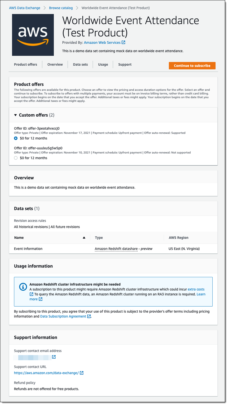
As a data subscriber I can browse through the AWS Data Exchange catalog and find data products that are relevant to my business, and subscribe to them.

Data providers can also create private offers and extend them to me for access via the AWS Data Exchange Console. I click My product offers, and review the offers that have been extended to me. I click on Continue to subscribe to proceed:

Then I complete my subscription by reviewing the offer and the subscription terms, noting the data sets that I will get, and clicking Subscribe:

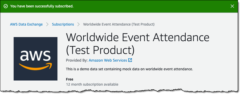
Once the subscription is completed, I am notified and can move forward:

From the Redshift Console, I click Datashares, select From other accounts, and I can see the subscribed data set:

Next, I associate it with one or more of my Redshift clusters by creating a database that points to the subscribed datashare, and use the tables, views, and stored procedures to power my Redshift queries and my applications.

AWS Data Exchange for Amazon Redshift – Publishing a Data Product
As a data provider I can include Redshift tables, views, schemas and user-defined functions in my AWS Data Exchange product. To keep things simple, I’ll create a product that includes just one Redshift table.

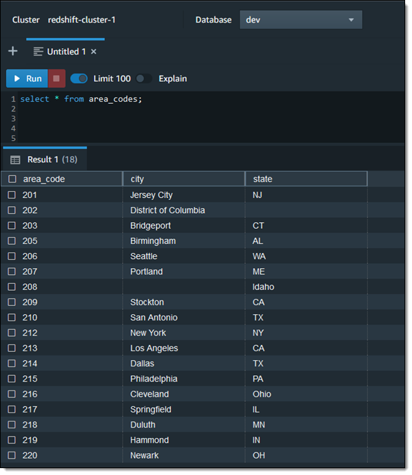
I use the spiffy new Redshift Query Editor V2 to create a table that maps US area codes to a city and a state:

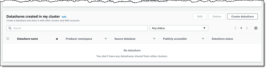
Then I examine the list of existing datashares for my Redshift cluster, and click Create datashare to make a new one:

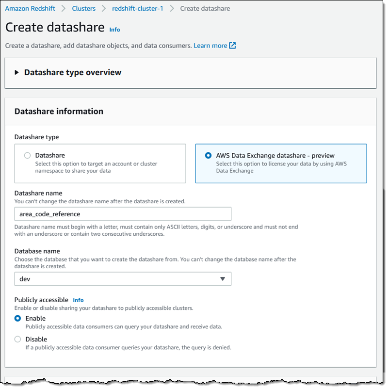
Next, I go through the usual process for creating a datashare. I select AWS Data Exchange datashare, assign a name (area_code_reference), pick the database within the cluster, and make the datashare accessible to publicly accessible clusters:

Then I scroll down and click Add to move forward:

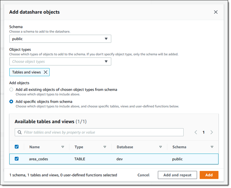
I choose my schema (public), opt to include only tables and views in my datashare, and then add the area_codes table:

At this point I can click Add to wrap up, or Add and repeat to make a more complex product that contains additional objects.

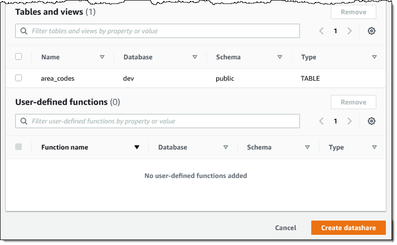
I confirm that the datashare contains the table, and click Create datashare to move forward:

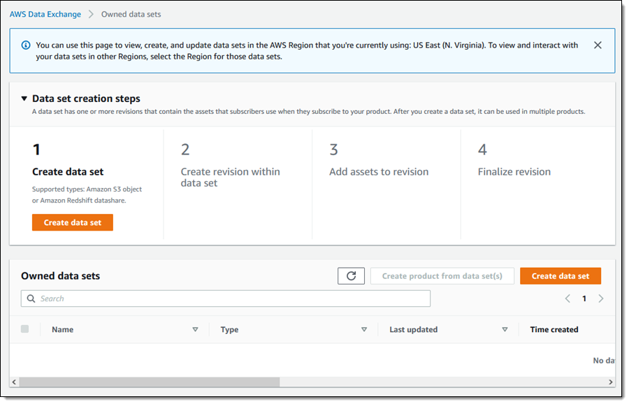
Now I am ready to start publishing my data! I visit the AWS Data Exchange Console, expand the navigation on the left, and click Owned data sets:

I review the Data set creation steps, and click Create data set to proceed:

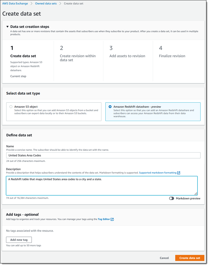
I select Amazon Redshift datashare, give my data set a name (United States Area Codes), enter a description, and click Create data set to proceed:

I create a revision called v1:

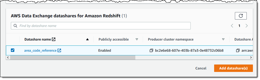
I select my datashare and click Add datashare(s):

Then I finalize the revision:

I showed you how to create a datashare and a dataset, and to publish a product using the console. If you are publishing multiple products and/or making regular revisions, you can automate all of these steps using the AWS Command Line Interface (CLI) and the Amazon Data Exchange APIs.

Initial Data Products
Multiple data providers are working to make their data products available to you through AWS Data Exchange for Amazon Redshift. Here are some of the initial offerings and the official descriptions:

  • FactSet Supply Chain Relationships – FactSet Revere Supply Chain Relationships data is built to expose business relationship interconnections among companies globally. This feed provides access to the complex networks of companies’ key customers, suppliers, competitors, and strategic partners, collected from annual filings, investor presentations, and press releases.
  • Foursquare Places 2021: New York City Sample – This trial dataset contains Foursquare’ss integrated Places (POI) database for New York City, accessible as a Redshift Data Share. Instantly load Foursquare’s Places data in to a Redshift table for further processing and analysis. Foursquare data is privacy-compliant, uniquely sourced, and trusted by top enterprises like Uber, Samsung, and Apple.
  • Mathematica Medicare Pilot Dataset – Aggregate Medicare HCC counts and prevalence by state, county, payer, and filtered to the diabetic population from 2017 to 2019.
  • COVID-19 Vaccination in Canada – This listing contains sample datasets for COVID-19 Vaccination in Canada data.
  • Revelio Labs Workforce Composition and Trends Data (Trial data) – Understand the workforce composition and trends of any company.
  • Facteus – US Card Consumer Payment – CPG Backtest – Historical sample from panel of SKU-level transaction detail from cash and card transactions across hundreds of Consumer-Packaged Goods sold at over 9,000 urban convenience stores and bodegas across the U.S.
  • Decadata Argo Supply Chain Trial Data – Supply chain data for CPG firms delivering products to US Grocery Retailers.

— Jeff;

Replace traditional email mailbox polling with real-time reads using Amazon SES and Lambda

Post Syndicated from agardezi original https://aws.amazon.com/blogs/messaging-and-targeting/replace-traditional-email-mailbox-polling-with-real-time-reads-using-amazon-ses-and-lambda/

Integrating emails into an automated workflow for automated processing can be challenging. Traditionally, applications have had to use the POP protocol to connect to mail servers and poll for emails to arrive in a mailbox and then process the messages inline and perform actions on the message. This can be an inefficient mechanism and prone to errors that result in the workflow missing messages. Since this method requires polling it’s not great if you need real-time processing of messages and introduces inefficiencies in the design. Amazon Simple Email Service (Amazon SES) is a cost effective, scalable and flexible email service with support for different workflows including the ability to perform spam checks and virus scans. In this blog you will see how to use Amazon SES with AWS Lambda and Amazon S3 in order to automate the processing of emails in real time and integrate with an application without the need for polling.

The use case explored in this blog focuses on automation for CRM or order processing platforms and processing of email related to customer contact or direct email requests. An example of this use case is copying a client engagement email to Salesforce (or any other database) where it is recorded and can later be categorized or attached to the appropriate client account or opportunity. When designing an application that needs to read emails from a mailbox, a developer would traditionally have to use a mail library (like JavaMail if using Java) to make a call to the mailbox, authenticate and then pull messages into an application object. This would mean polling the mailbox every 10 – 15 minutes to check for new messages, handle errors when the mailbox is unavailable and maintaining a fully functioning mailbox. This solution can help you implement automated processing of emails arriving in a mailbox without the need to poll the mailbox. The entire solution will be implemented in a serverless fashion.

Solution

This blog post shows how to use SES to perform automated processing of email in an application workflow. I will use the option in SES to save received emails in S3 and trigger a Lambda function to process the message without having to poll a mailbox. This sample application demo is using email to receive simple orders which get automatically processed and the details stored in DynamoDB. The following diagram shows the high-level architecture:

Step 1: Create an S3 Bucket for Email Storage

Start by creating an S3 bucket where received emails will be stored in order for the full email to be processed by the lambda. The bucket must have a policy attached so SES can put objects in the bucket on your behalf:

{
  "Version":"2012-10-17",
  "Statement":[
    {
      "Sid":"AllowSESPuts",
      "Effect":"Allow",
      "Principal":{
        "Service":"ses.amazonaws.com"
      },
      "Action":"s3:PutObject",
      "Resource":"arn:aws:s3:::myBucket/*",
      "Condition":{
        "StringEquals":{
          "aws:Referer":"111122223333"
        }
      }
    }
  ]
}

Make the following changes to the preceding policy example:

  1. Replace myBucket with the name of the Amazon S3 bucket that you want to write to.
  2. Replace 111122223333 with your AWS account ID.

You can find out more about the policy here.

Step 2: Create DynamoDB Table to Simulate Application

Next, add a DynamoDB table. The DynamoDB table will store the incoming order info. For this sample we will keep it simple and have a table with email as a partition key. Here is the data model:

{   
    "email_order_received": {
        "email": "string",
        "itemname": "string",
        "quantity": "number"
    }   
}

Step 3: Create Lambda Function triggered by SES to Process Email

Now the DynamoDB table is ready, create the Lambda function to process the email and send data to the DynamoDB table. The lambda function needs an execution role that has permissions to access the S3 bucket, the DynamoDB table and create the CloudWatch log group. It also needs a Resource-based Policy so SES can invoke the Lambda function. In the final step when we configure SES to call the lambda, SES automatically adds the necessary permissions to the function as detailed here.  This is a sample policy statement:

{
  "Version": "2012-10-17",
  "Id": "default",
  "Statement": [
    {
      "Sid": "allowSesInvoke",
      "Effect": "Allow",
      "Principal": {
        "Service": "ses.amazonaws.com"
      },
      "Action": "lambda:InvokeFunction",
      "Resource": "arn:aws:lambda:eu-west-1:111122223333:function:email-event-ses",
      "Condition": {
        "StringEquals": {
          "AWS:SourceAccount": "111122223333"
        }
      }
    }
  ]
}

Sample Lambda code in python:

import boto3
import email


def lambda_handler(event, context):
    s3 = boto3.client("s3")
    dynamodb = boto3.resource("dynamodb")
    table = dynamodb.Table('email_order_received')
    
    print("Spam filter")
    # Check the SES spam and virus filter settings
    if (
        event["Records"][0]["ses"]["receipt"]["spfVerdict"]["status"] == "FAIL" or
        event["Records"][0]["ses"]["receipt"]["dkimVerdict"]["status"] == "FAIL" or
        event["Records"][0]["ses"]["receipt"]["spamVerdict"]["status"] == "FAIL" or
        event["Records"][0]["ses"]["receipt"]["virusVerdict"]["status"] == "FAIL"
       ):
        print("Dropping Spam")
    else:
        print("Not Spam")
        email_bucket = "email-handling-test"
        bucketkey = "monitor/" + event["Records"][0]["ses"]["mail"]["messageId"]
    
        fileObj = s3.get_object(Bucket = email_bucket, Key=bucketkey)
    
        msg = email.message_from_bytes(fileObj['Body'].read())
        From = msg['From']
        itemname = msg['Subject']
        body = ""
        if msg.is_multipart():
            for part in msg.walk():
                type = part.get_content_type()
                disp = str(part.get('Content-Disposition'))
                # look for plain text parts, but skip attachments
                if type == 'text/plain' and 'attachment' not in disp:
                    charset = part.get_content_charset()
                    # decode the base64 unicode bytestring into plain text
                    body = part.get_payload(decode=True).decode(encoding=charset, errors="ignore")
                    # if we've found the plain/text part, stop looping thru the parts
                    break
        else:
            # not multipart - i.e. plain text, no attachments
            charset = msg.get_content_charset()
            body = msg.get_payload(decode=True).decode(encoding=charset, errors="ignore")
            
        table.put_item(
            Item={
                'email': From,
                'itemname': itemname,
                'quantity': body
            }
        )
        print("inserted data into dynamodb")

When you add a Lambda action to a receipt rule, Amazon SES sends an event record to Lambda every time it receives an incoming message. This event contains information about the email headers for the incoming message, as well as the results of tests (spam filtering and virus scanning) that Amazon SES performs on incoming messages, however it omits the body of the incoming email. This is why the lambda has to process the body form the email stored in S3. You can see details of the event here. In this demo app we assume the item name is in the subject and the body of the email has the quantity of the items and this data is written to the DynamoDB table.

Step 4: Configure SES to Send Emails to S3 and Trigger Lambda Function

The final step is to configure Amazon SES. Start by verifying a domain so SES can use it to send and receive emails. Domain verification helps ensure you are the owner of the domain and are thus authorised to manage the sending and receiving of the emails from addresses in the domain. To verify your domain:

  1. In the SES console in the navigation pane under Identity Management, choose Domains.
  2. Choose Verify new Domain
  3. In the Verify new Domain dialog enter your domain name
  4. Choose Verify This Domain
  5. In the dialogue box you will see a Domain verification record set. You need to add this record to your domain DNS server. You will also have to add the email receiving record (MX Record) to you domain DNS server.
  6. If your DNS server is Route53 and it is registered under the same account then SES also gives you the option to update your DNS server from within the SES console.

Once the domain is verified its status goes from “pending verification” to “verified” and now it can used it to send and receive emails.

Next, create a recipient rule set. The Rule Set lets you specify what SES does with emails it receives on domains you own. You can create rules for individual addresses or any address under the domain. To create the Rule Set:

  1. In the left navigation pane, under Email Receiving, choose Rule Sets.
  2. Choose Create Rule.
  3. Enter the recipient email address you want to configure the rule for. You can add up to a maximum of 100 recipient addresses or just set it up for any address in the domain using just the domain name as a wildcard.
  4. Once the addresses have been added, add the actions for the rule. Add two actions:
    1. First one is of type S3, this is to save a copy of the email to the S3 bucket created in step 1. Select the bucket name created in step 1 from the drop-down list. You can add a prefix to the filename as well to categorise the output of different rules.
    2. Second is of type Lambda to trigger the lambda for processing the email. Select the lambda created in step 3 from the drop-down list.

Once the SES Rule is configured, we have the full workflow in place. Now any email sent to the [email protected] address will be processed by the Lambda. In this way you can configure email processing to be part of your application workflow without having to perform polling.

Clean-up

To clean up the resources used in your account:

  1. Navigate to Amazon S3 and delete the contents of the bucket you created where your emails are stored.
  2. Once the bucket is empty, delete the bucket.
  3. Navigate to the DynamoDB console and delete the table you created above. Make sure you select the option to “Delete all CloudWatch alarms for this table”
  4. Remove the domain from Amazon SES. To do this, navigate to the Amazon SES Console and choose Domains from the left navigation. Select the domain you want to remove and choose Remove button to remove it from Amazon SES.
  5. From the Amazon SES Console, navigate to the Rule Sets from the left navigation. On the Active Rule Set section, choose View Active Rule Set button and delete all the rules you have created, by selecting the rule and choosing Action, Delete.
  6. On the Rule Sets page choose Disable Active Rule Set button to disable listening for incoming email messages.
  7. On the Rule Sets page, Inactive Rule Sets section, delete the only rule set, by selecting the rule set and choosing Action, Delete.
  8. Navigate to the Lambda console and delete the Lambda you created earlier. Select the Lambda and choose Delete from the Actions menu.
  9. Navigate to CloudWatch console and from the left navigation choose Logs, Log groups. Find the log group that belongs to the resources and delete it by selecting it and choosing Actions, Delete log group(s).

Conclusion

In this post, we have shown you how to integrate email processing into an application workflow without having to resort to polling a mail box.

By using SES to receive emails you can create a modular serverless architecture that allows emails to be processed and checked for spam plus viruses and the output can then be sent to any downstream system or stored in a database for application use.


About the Author

Syed Ali Abbas Gardezi is a Sr. Solution Architect for AWS based in London, United Kingdom. He works with AWS GSI Partners architecting, designing and implementing various large-scale IT solution. Before joining AWS he worked in several Architecture roles in a tier 1 financial organisation in London.

Designing a High-volume Streaming Data Ingestion Platform Natively on AWS

Post Syndicated from Soonam Jose original https://aws.amazon.com/blogs/architecture/designing-a-high-volume-streaming-data-ingestion-platform-natively-on-aws/

The total global data storage is projected to exceed 200 zettabytes by 2025. This exponential growth of data demands increased vigilance against cybercrimes. Emerging cybersecurity trends include increasing service attacks, ransomware, and critical infrastructure threats. Businesses are changing how they approach cybersecurity and are looking for new ways to tackle these threats. In the past, they have relied on internal IT or engaged a managed security services provider (MSSP) to monitor and prevent unauthorized access and attacks.

An end-to-end analytics solution should ingest and process log data streaming from various computing and IoT devices. It can then make processed data available to analytics systems users in near-real-time. However, the sheer volume of data in the future makes this difficult to address in a reliable and cost-effective manner.

In this blog post, we present three approaches for a high-volume log data ingestion and processing platform natively on Amazon Web Services (AWS). We also compare the pros and cons of each. We’ll discuss factors to consider when evaluating the different options and their associated flexibility, to take full advantage of AWS. We will showcase a fictional use case for a top MSSP who ingests high volumes of logs from security devices to cloud. This MSSP also performs downstream analytics and threat detection modeling.

The options we present here have a log collection platform (LCP) on-premises. It collects logs from security devices and sensors, performs necessary translations and tokenization, and pushes compressed log files to the processing tier on cloud. The collection platform can also be modernized to have the IoT-enabled devices send logs to AWS IoT services. This will push the data to Amazon Kinesis, a managed service for collecting and analyzing streaming data.

Approach 1: Amazon Kinesis for log ingestion and format conversion

Figure 1 illustrates a comprehensive solution that uses managed and serverless services on AWS.

Figure 1. Amazon Kinesis for log ingestion and format conversion

Figure 1. Amazon Kinesis for log ingestion and format conversion

1. LCP will invoke a scalable producer application for Amazon Kinesis Data Streams running on AWS Fargate behind an Application Load Balancer. The producer application will use the Amazon Kinesis Producer Library (KPL). KPL aggregates and batches data records to make ingestion into the data stream more efficient. The application may provide compressed records to the KPL to have it manage object compression.

The application can be set up as an HTTP endpoint that receives log files and processes them using KPL. Customer ID sent as part of an HTTP request header can be used to maintain affinity. The application can run in a Docker container, which is orchestrated by Amazon ECS on AWS Fargate. A target tracking scaling policy can manage the number of parallel running data ingestion containers to manage scalability of the ingestion process.

2. Amazon Kinesis Scaling Utility can be used to scale data streams up or down by a count, or as a percentage of the total fleet. The scaling utility archive file can be imported as a library to AWS Lambda. It will automatically manage the number of shards in the stream based on the observed PUT or GET rate of the stream. The combination of customer ID and security device ID may be used to define the partition key.

3. Records uploaded to the stream by the producer application will be consumed by Lambda. It will perform gateway transformations (required by all downstream consumers) and the normalization of record format. Any additional consumer level transformations may be handled separately, associated with respective consumers.

A combination of batch window and batch size configurations can improve efficiency of function invocations. Batch windows are the maximum amount of time in seconds to gather records before invoking the function. Batch size is the number of records to send to the function in each batch. The Lambda function will throttle sending records to Amazon Kinesis Data Firehose. Error handling will be accomplished via retries with a smaller batch size, with number of retries limited as appropriate. It will discard records that are too old.

An Amazon Simple Queue Service (SQS) queue can be configured as a failed-event destination for further offline analysis. A Lambda function can read from the error SQS queue to do basic checks and determine appropriate follow-up actions. This can be an initiated email for additional investigation or a command to discard the message.

4. Output of transformations by Lambda will be saved to the short term (hot) storage Amazon S3 bucket via Kinesis Data Firehose. This can efficiently handle Parquet format conversion required by downstream analytics applications. Kinesis Data Firehose delivery streams will be created per customer and configured with associated AWS Glue Data Catalog table, to perform parquet format conversion.

5. AWS Glue jobs will be used to consolidate and write larger files to the long term (cold) storage bucket.

6. The data in the cold storage bucket will be accessed by internal SOC analysts for threat detection and mitigation.

7. The data in cold storage buckets will also be accessed by end customers via dashboards in Amazon QuickSight.

8. This architecture also provides additional options to modernize streaming analytics using Amazon Kinesis Data Analytics or AWS Glue streaming jobs as appropriate.

While this architecture proposes a fully managed, end-to-end solution, the sheer volume of log messages may drive up the total cost of the solution. This is especially true for Kinesis Data Streams and Kinesis Data Firehose costs.

Approach 2: Containerized application on AWS Fargate for ingestion and Amazon Kinesis for format conversion

An alternative approach shown in Figure 2 replaces the gateway Kinesis Data Streams and transformations, with a containerized application on Fargate. Conversion to Parquet format and writing to the S3 bucket is still handled by Kinesis Data Firehose.

Figure 2. Containerized application for ingestion and Amazon Kinesis for format conversion

Figure 2. Containerized application for ingestion and Amazon Kinesis for format conversion

1. LCP will upload log files to a raw storage bucket in Amazon S3.

2. A Lambda function will process Event Notifications from the raw data storage bucket. It can insert Amazon S3 object pointers to a Kinesis Data Stream partitioned by Customer ID and Device ID.

3. The producer application will retrieve the Event Notifications from the Data Stream and retrieve corresponding log files from S3. It will perform initial aggregations and transformations, and output to Kinesis Data Firehose. The application can run in a Docker container that is orchestrated by Amazon ECS on Fargate. A target tracking scaling policy can manage the number of parallel running data ingestion containers, to manage scalability of the ingestion process. ECS cluster capacity can be scaled up or down based on Amazon CloudWatch alarms.

4. Kinesis Data Firehose converts to Parquet format, zips the data, and persists to a short-term storage bucket in S3. This is backed by Glue Data Catalog.

Steps 5, 6 and 7 perform consolidation and availability of the processed data to downstream consumers, as in the previous approach.

This option uses the built-in capabilities of Kinesis Data Firehose to transform to Parquet format and deliver to S3. Note that higher costs associated with the service may still be cost prohibitive for larger data volumes.

Approach 3: Containerized application on AWS Fargate for ingestion and format conversion

Figure 3 uses a containerized application running on Fargate for both gateway transformations. This app also provides conversion to Parquet format before writing the files to a short term (hot) storage bucket. All the other steps are the same as in option 2.

Figure 3. Containerized application for ingestion and format conversion

Figure 3. Containerized application for ingestion and format conversion

This option offers the least expensive way to transform, aggregate, and enrich the incoming log records, as well as convert them to Parquet format. But it comes with additional overhead for custom development of format conversion, checkpointing, error handling, and application management. Evaluate based on your business needs and workflow.

Conclusion

In this post, we discussed multiple approaches to design a platform on AWS to ingest and process high-volume security log records. We compared the pros and cons for each option. Amazon Kinesis is a fully managed and scalable service that helps easily collect, process, and analyze video and data streams in real time. A solution primarily based on Kinesis may become cost prohibitive due to large data volumes. Consider alternate approaches that use containerized applications on AWS Fargate. The trade-off would be the ability for custom development versus application management overhead.

To improve your security log analysis solution, explore one of the approaches we illustrate and customize as appropriate to fit your unique needs.

SFC files suit against Vizio over GPL violations

Post Syndicated from original https://lwn.net/Articles/873338/rss

Software Freedom Conservancy has announced that it filed suit against TV maker Vizio over “repeated failures to fulfill even the basic requirements of the General Public License (GPL)“. The organization raised the problems with Vizio in August 2018, but the company stopped responding in January 2020, according to the announcement.

“We are asking the court to require Vizio to make good on its obligations under copyleft compliance requirements,” says [Software Freedom Conservancy executive director Karen[ Sandler. She explains that in past litigation, the plaintiffs have always been copyright holders of the specific GPL code. In this case, Software Freedom Conservancy hopes to demonstrate that it’s not just the copyright holders, but also the receivers of the licensed code who are entitled to rights.

The lawsuit suit seeks no monetary damages, but instead seeks access to the technical information that the copyleft licenses require Vizio to provide to all customers who purchase its TVs (specifically, the plaintiff is asking for the technical information via “specific performance” rather than “damages”).

The complaint is also available.

Software Freedom Conservancy files lawsuit against Vizio Inc.

Post Syndicated from original https://lwn.net/Articles/873336/rss

Software Freedom Conservancy announced
it has filed a lawsuit
against California TV manufacturer Vizio
Inc. for GPL violations.

The lawsuit alleges that Vizio’s TV products, built on its SmartCast
system, contain software that Vizio unfairly appropriated from a community
of developers who intended consumers to have very specific rights to
modify, improve, share, and reinstall modified versions of the software.

[…] Software Freedom Conservancy, a nonprofit organization focused on
ethical technology, is filing the lawsuit as the purchaser of a product
which has copylefted code. This approach makes it the first legal case that
focuses on the rights of individual consumers as third-party beneficiaries
of the GPL.

OWASP Top 10 Deep Dive: Injection and Stack Traces From a Hacker’s Perspective

Post Syndicated from Julius Callahan original https://blog.rapid7.com/2021/10/19/owasp-top-10-deep-dive-injection-and-stack-traces-from-a-hackers-perspective/

OWASP Top 10 Deep Dive: Injection and Stack Traces From a Hacker's Perspective

In case you missed it, injection claimed the number 3 spot in OWASP’s updated Top 10 application security risks for 2021. Today, I’m going to highlight some of the reasons why injection is such a formidable threat, despite it falling two spaces from the number 1 slot on OWASP’s 2017 list.

But before we begin, I’d like to start off with a short but true story of how I got here.

The 3 letters that changed my life

A few decades ago, back in my web development days, I was working on a community-type website. This was post-MySpace and pre-Facebook — so yeah, that long ago. Back then, CMSs like WordPress and Joomla were just taking off but still all the rage. So with the LAMP stack complete and the CMS deployed, it was time to install the community component for the website. There weren’t many third-party solutions available back then — so when I found a component that offered individual profiles, message boards, picture uploads, AND a chat, I jumped on it.

A few days into getting the website configured and running, I noticed another admin user in the DB. My first thought was, “I don’t remember creating a second admin account,” and my second thought was, “Oh no, I’ve been hacked”.

Turns out the latter was true. Not even a week into building the website, it was hacked.

Now, any sane developer would have immediately torn down the server, scrambled for backups, searched for a different hosting provider, and started over. But not me — I needed to know how this happened. So I went straight to the horse’s mouth: I asked the person who hacked my site.

Remember when I mentioned the community component had a chat function? I used it to send the hacker a message: “How did you get in here?” Sure enough, a day later I received a reply of 3 simple letters that I will never forget: “SQL.”

From that day on, I knew what I wanted to do for the rest of my life. So to the hacker, whoever and wherever you are out there, thank you.

Which brings me to OWASP’s new top 10 for 2021 and our focus for this post: A03, aka injection.

What is injection, and how are attackers using it today?

I like to think of injection as a family of vulnerabilities. It can include everything from SQL and XSS — the rock stars of injection — to improper control of resource identifiers, which basically cover anything with the ability to significantly change the flow of a given process. In some cases, injection can even include the execution of arbitrary code. It should come as no surprise, then, that there are currently over 32 mapped CWEs for injection.

Many things have changed since my web developer days, but a lot has stayed the same. One would like to think the days of SQL injection, or any injection for that matter, are long gone. Sadly, that isn’t the case. While injection has been dethroned from first to third place on the new OWASP 2021 Top 10 list, it’s still very much alive in today’s web applications.

The good news is that the majority of injection issues I see today are a bit more benign than those from the past. They tend to be less likely to yield the fruitful database dumps, auth bypass, or occasional defacement we’ve all come to know so well. Don’t get me wrong — there are plenty of apps out there that are eager to give up their sensitive data because of unexpected and improperly handled input, though it does seem those numbers are on the decline. But for the apps that are a little more reluctant to share sensitive information via injection, they do so in another way: stack traces.

Stack traces sometimes do stack up

Developers have a love-hate relationship with stack traces. On the one hand, they’re helpful in spotting errors in the code they write. On the other hand, they point out the errors in the code they write.

To those that are new to the phrase “stack trace,” it refers to an error in the code that was last run by the application before it crashed. Basically, when something happens that the code isn’t prepared to handle, it spits out a bunch of technical information onto the screen so the developer can spot the issue and correct it. Stack traces have been around since the dawn of programming, and they remain a popular method of debugging an application.

For our conversation, let’s focus on the production environment of an application and highlight why stack traces in this scenario are bad for two main reasons.

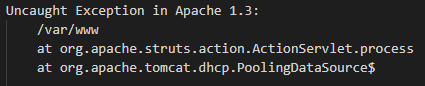
First, they look terrible and are a bad user experience. When browsing an e-commerce product site, “NullPointerException” should not be one of the results. And I don’t recall “/var/www/” being part of my search string when looking for a new pair of sunglasses.

Second, most stack traces tend to divulge more sensitive information than they need to. This is by design — and while it might be helpful to the developer, it can also be all too helpful to an attacker.

So how does one “inject” something into a web application — and what role do stack traces play in this process? Well for the most part, and to keep things simple, GET and POST methods are a great place to start.

Say you come across a URL that ends with this path:

/search_get_by_id.php?id=3

Replace the 3 with a single tick so it looks like this:

/search_get_by_id=’

Now, instead of showing the results for an item with the ID of 3, the application gets confused by the single tick and throws a stack trace like this:

Invalid ProductError 1064: You have an error in your SQL syntax; check the manual that corresponds to your MySQL server version for the right syntax to use near ”’ at line 1 of SELECT * FROM inventory WHERE id = ‘

Or maybe you’re updating some personal information on a website, but instead of entering in your email address, you enter “<script>alert(document.cookie)</script>” or 1,000 letter As into the parameter instead.

All these examples are forms of injection, and if done correctly, they can do some serious damage to an application. And the best-worst-case scenario for an attacker is that the application yields a stack trace instead of doing whatever it was they were initially trying to do. Either way, it’s a win-win scenario for the attacker.

How stack traces make hackers’ jobs easier

The average person who encounters a stack trace when visiting a website may not think anything other than, “Yikes, I don’t know what this is, so I’m going to hit the back button or try re-entering in my information.” However, an attacker will have a much different reaction — probably something like “YES!” or “FINALLY!”

You see, attackers love stack traces because of the information they yield. They spend hours or even days trying to get an application to throw a stack trace. While the untrained eye sees a mess of gobbledygook on the page, an attacker sees very valuable information that brings them another step closer to their goal.

In the following examples, I’ll give an overview of how an attacker views these stack traces.

*The images depicted below are entirely made up but do contain real snippets from actual stack traces. They’ve also been exaggerated for educational purposes.

Example 1: MySql

OWASP Top 10 Deep Dive: Injection and Stack Traces From a Hacker's Perspective

Things we know:

  • The application is running on a Windows machine, possibly a 32bit OS like XP or NT, judging from the file path.
  • The app is running an outdated and vulnerable version of MySQL.
  • There are multiple critical CVEs for this version of MySQL, everything from Denial of Service attacks to privilege escalation and remote code execution.

Example 2: Laravel PHP

OWASP Top 10 Deep Dive: Injection and Stack Traces From a Hacker's Perspective

Things we know:

  • The application is running on a Windows machine, based on the file path.
  • It’s running XAMPP (multiple known vulnerabilities).
  • It’s also running MySQL (multiple known vulnerabilities).
  • In addition, it’s running a vulnerable version of the PHP Laravel Framework 5.5 CVE-2018-15133.
  • This version of Laravel is susceptible to remote code execution, among other exploits.

Example 3: Apache

OWASP Top 10 Deep Dive: Injection and Stack Traces From a Hacker's Perspective

Things we know:

  • The application is running on a Linux box based on the file path.
  • It’s running Apache Struts (multiple known critical vulnerabilities).
  • It’s also running Apache Tomcat (multiple known critical vulnerabilities).
  • In addition, it’s running a vulnerable version of Apache web server.
  • This version of Apache is susceptible to multiple critical CVEs ranging from Denial of Service attacks to privilege escalation and remote code execution.

Example 4: Java

OWASP Top 10 Deep Dive: Injection and Stack Traces From a Hacker's Perspective

Things we know:

  • The application is running on a Linux box based on the file path.
  • It’s running Spring Framework (multiple known vulnerabilities).
  • It’s also running a vulnerable version of Java.
  • This version of Java is so vulnerable Oracle won’t even give you a specific vulnerability, only that it contains multiple critical CVEs ranging from remote access to self-destruction. I am exaggerating… only slightly, but you get the point.

So while injection went from gold to bronze on the new OWASP Top 10 list for 2021, attackers can and do still use it to produce a treasure trove of information — stack traces being one of those tried-and-true methods.

That said, I’m happy to see that injection has been knocked down a few pegs — this shows that the web industry has managed to move the needle forward by way of security. With the rise of even more popular frameworks that have some security baked in, and the ever-increasing concern for secure apps, developers are seeing security injected into their day-to-day (no pun intended). Whether it be SAST or DAST scanning hooked into their CI/CD, RASPs or WAFs deployed to detect attacks, or even the occasional pen test, security is becoming more and more part of the software development life cycle, and that is awesome.

Who knows? Maybe in another 4 years, injection won’t even make the top 10. If it does, you can bet I’ll write another blog about it.

Stay tuned for future installments in our series of deep dives into OWASP’s updated Top 10 list of application security threats for 2021.

NEVER MISS A BLOG

Get the latest stories, expertise, and news about security today.

AWS Control Tower Account vending through Amazon Lex ChatBot

Post Syndicated from Marco Fischer original https://aws.amazon.com/blogs/devops/aws-control-tower-account-vending-through-amazon-lex-chatbot/

In this blog post you will learn about a multi-environment solution that uses a cloud native CICD pipeline to build, test, and deploy a Serverless ChatOps bot that integrates with AWS Control Tower Account Factory for AWS account vending. This solution can be used and integrated with any of your favourite request portal or channel that allows to call a RESTFUL API endpoint, for you to offer AWS Account vending at scale for your enterprise.

Introduction

Most of the AWS Control Tower customers use the AWS Control Tower Account Factory (a Service Catalog product), and the ServiceCatalog service to vend standardized AWS Services and Products into AWS Accounts. ChatOps is a collaboration model that interconnects a process with people, tools, and automation. It combines a Bot that can fulfill service requests (the work needed) and be augmented by Ops and Engineering staff in order to allow approval processes or corrections in the case of exception request. Major tasks in the public Cloud go toward building a proper foundation (the so called LandingZone). The main goals of this foundation are providing not only an AWS Account access (with the right permissions), but also the correct Cloud Center of Excellence (CCoE) approved products and services. This post demonstrates how to utilize the existing AWS Control Tower Account Factory, extending the Service Catalog portfolio in Control Tower with additional products, and executing Account vending and Product vending through an easy ChatBot interface. You will also learn how to utilize this Solution with Slack. But it can also be easily utilized with Chime/MS Teams or a normal Web-frontend, as the integration is channel-agnostig through an API Gateway integration layer. Then, you will combine all of this, integrating a ChatBot frontend where users can issue requests against the CCoE and Ops team to fulfill AWS services easily and transparently. As a result, you experience a more efficient process for vending AWS Accounts and Products and taking away the burden on your Cloud Operations team.

Background

  • An AWS Account Factory Account account is an AWS account provisioned using account factory in AWS Control Tower.
  • AWS Service Catalog lets you to centrally manage commonly deployed IT services. For this blog, account factory utilizes AWS Service Catalog to provision new AWS accounts.
  • A Control Tower provisioned product is an instance of the Control Tower Account Factory product that is provisioned by AWS Service Catalog. In this post, any new AWS account created through the ChatOps solution will be a provisioned product and visible in Service Catalog.
  • Amazon Lex: is a service for building conversational interfaces into any application using voice and text

Architecture Overview

The following architecture shows the overview of the solution which will be built with the code provided through Github.

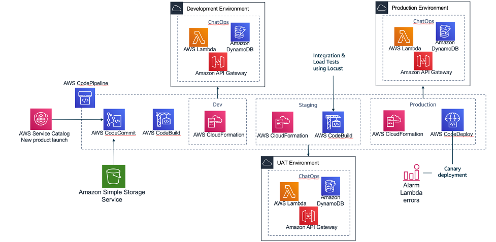
Multi-Environment CICD Architecture

The multi-environment pipeline is building 3 environments (Dev, Staging, Production) with different quality gates to push changes on this solution from a “Development Environment” up to a “Production environment”. This will make sure that your AWS ChatBot and the account vending is scalable and fully functional before you release it to production and make it available to your end-users.

  • AWS Code Commit: There are two repositories used, one repository where Amazon Lex bot is created through a Java-Lambda function and installed in STEP 1. And one for the Amazon Lex bot APIs that are running and capturing the Account vending requests behind API Gateway and then communicating with the Amazon Lex Bot.
  • AWS Code Pipeline: It integrates CodeCommit and CodeBuild and CodeDeploy, to be manage your release pipelines moving from Dev to Production.
  • AWS Code Build: Each different activity executed inside the pipeline is a CodeBuild activity. Inside the source code repository there are different files with the prefix buildspec-. Each of these files contains the exact commands that the code build must execute on each of the stages: build/test.
  • AWS Code Deploy: Tthis is an AWS service that manages the deployment of the serverless application stack. In this solution it implements a canary deployment where in the first minute we switch 10% of the requests to the new version of it which will allow to test the scaling of the solution. (CodeDeployDefaultLambdaCanary10Percent5Minutes)

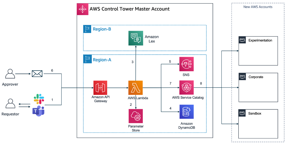
AWS ControlTower Account Vending integration and ChatOps bot architecture

AWS ControlTower Account Vending integration and ChatOps bot architecture

The actual Serverless Application architecture built with Amazon Lex and the Application code in Lambda accessible through Amazon API Gateway, which will allow you to integrate this solution with almost any front-end (Slack, MS Teams, Website).

  • Amazon Lex: With Amazon Lex, the same deep learning technologies that power Amazon Alexa are now available to any developer, enabling you to quickly and easily build sophisticated, natural language, conversational bots (“chatbots”). As Amazon lex is not available yet in all AWS regions that currently AWS Control Tower is supported, it may be that you want to deploy Amazon Lex in another region than you have AWS Control Tower deployed.
  • Amazon API Gateway / AWS Lambda: The API Gateway is used as a central entry point for the Lambda functions (AccountVendor) that are capturing the Account vending requests from a frontend (e.g. Slack or Website). As Lambda functions can not be exposed directly as a REST service, they need a trigger which in this case API Gateway does.
  • Amazon SNS: Amazon Simple Notification Service (Amazon SNS) is a fully managed messaging service. SNS is used to send notifications via e-mail channel to an approver mailbox.
  • Amazon DynamoDB: Amazon DynamoDB is a key-value and document database that delivers single-digit millisecond performance at any scale. It’s a fully managed, multi-region, multi-active, durable database. Amazon DynamoDB will store the Account vending requests from the Lambda code that get triggered by the Lex-bot interaction.

Solution Overview and Prerequisites

Solution Overview

Start with building these 2 main components of the Architecture through an automated script. This will be split into “STEP 1”, and “STEP 2” in this walkthrough. “STEP 3” and “STEP 4” will be testing the solution and then integrating the solution with a frontend, in this case we use Slack as an example and also provide you with the Slack App manifest file to build the solution quickly.

  • STEP 1) “Install Amazon Lex Bot”: The key part of the left side of the Architecture, the Amazon Lex Bot called (“ChatOps” bot) will be built in a first step, then
  • STEP 2) “Build of the multi-environment CI/CD pipeline”: Build and deploy a full load testing DevOps pipeline that will stresstest the Lex bot and its capabilities to answer to requests. This will build the supporting components that are needed to integrate with Amazon Lex and are described below (Amazon API Gateway, AWS Lambda, Amazon DynamoDB, Amazon SNS).
  • STEP 3) “Testing the ChatOps Bot”: We will execute some test scripts through Postman, that will trigger Amazon API Gateway and trigger a sample Account request that will require a feedback from the ChatOps Lex Bot.
  • STEP 4) “Integration with Slack”: The final step is an end-to-end integration with an communication platform solution such as Slack.

The DevOps pipeline (using CodePipeline, CodeCommit, CodeBuild and CodeDeploy) is automatically triggered when the stack is deployed and the AWS CodeCommit repository is created inside the account. The pipeline builds the Amazon Lex ChatOps bot from the source code. The Step 2 integrates the surrounding components with the ChatOps Lex bot in 3 different environments: Dev/Staging/Prod. In addition to that, we use canary deployment to promote updates in the lambda code from the AWS CodeCommit repository. During the canary deployment we implemented the rollback procedure using a log metric filter that scans the word Exception inside the log file in CloudWatch. When the word is found, an alarm is triggered and deployment is automatically rolled back. Usually, the rollback will occur automatically during the load test phase. This would prevent faulty code from being promoted into the production environment.

Prerequisites

For this walkthrough, you should have the following prerequisites ready. What you’ll need:

  • An AWS account
  • A ready AWS ControlTower deployment (needs 3 AWS Accounts/e-mail addresses)
  • AWS Cloud9 IDE or a development environment with access to download/run the scripts provided through Github
  • You need to log into the AWS Control Tower management account with AWSAdministratorAccess role if using AWS SSO or equivalent permissions if you are using other federations.

Walkthrough

To get started, you can use Cloud9 IDE or log into your AWS SSO environment within AWS Control Tower.

  1. Prepare: Set up the sample solution

Log in to your AWS account and open Cloud9.

1.1. Clone the GitHub repository to your Cloud9 environment.

The complete solution can be found at the GitHub repository here. The actual deployment and build are scripted in shell, but the Serverless code is in Java and uses Amazon Serverless services to build this solution (Amazon API Gateway, Amazon DynamoDB, Amazon SNS).

git clone https://github.com/aws-samples/multi-environment-chatops-bot-for-controltower

  1. STEP 1: Install Amazon Lex Bot

Amazon Lex is currently not deployable natively with Amazon CloudFormation. Therefore the solution is using a custom Lambda resource in Amazon CloudFormation to create the Amazon Lex bot. We will create the Lex bot, along some sample utterances, three custom slots (Account Type, Account E-Mail and Organizational OU) and one main intent (“Control Tower Account Vending Intent”) to capture the request to trigger an AWS Account vending process.

2.1. Start the script, “deploy.sh” and provide the below inputs. Select a project name. You can override it if you wan’t to choose a custom name and select the bucket name accordingly (we recommend to use the default names)

./deploy.sh

Choose a project name [chatops-lex-bot-xyz]:

Choose a bucket name for source code upload [chatops-lex-bot-xyz]:

2.2. To confirm, double check the AWS region you have specificed.

Attention: Make sure you have configured your AWS CLI region! (use either 'aws configure' or set your 'AWS_DEFAULT_REGION' variable).

Using region from $AWS_DEFAULT_REGION: eu-west-1

2.3. Then, make sure you choose the region where you want to install Amazon Lex (make sure you use an available AWS region where Lex is available), or use the default and leave empty. The Amazon Lex AWS region can be different as where you have AWS ControlTower deployed.

Choose a region where you want to install the chatops-lex-bot [eu-west-1]:

Using region eu-west-1

2.4. The script will create a new S3 bucket in the specified region in order to upload the code to create the Amazon Lex bot.

Creating a new S3 bucket on eu-west-1 for your convenience...
make_bucket: chatops-lex-bot-xyz
Bucket chatops-lex-bot-xyz successfully created!

2.5. We show a summary of the bucket name and the project being used.

Using project name................chatops-lex-bot-xyz
Using bucket name.................chatops-lex-bot-xyz

2.6 Make sure that if any of these names or outputs are wrong, you can still stop here by pressing Ctrl+c.

If these parameters are wrong press ctrl+c to stop now...

2.7 The script will upload the source code to the S3 bucket specified, you should see a successful upload.

Waiting 9 seconds before continuing
upload: ./chatops-lex-bot-xyz.zip to s3://chatops-lex-bot-xyz/chatops-lex-bot-xyz.zip

2.8 Then, the script will trigger an aws cloudformation package command, that will use the uploaded zip file, reference it and generate a ready CloudFormation yml file for deployment. The output of the generated package-file (devops-packaged.yml) will be stored locally and used to executed the aws cloudformation deploy command.

Successfully packaged artifacts and wrote output template to file devops-packaged.yml.

Note: You can ignore this part below as the shell script will execute the “aws cloudformation deploy” command for you.

Execute the following command to deploy the packaged template

aws cloudformation deploy --template-file devops-packaged.yml --stack-name <YOUR STACK NAME>

2.9 The AWS CloudFormation scripts should be running in the background

Waiting for changeset to be created..
Waiting for stack create/update to complete
Successfully created/updated stack - chatops-lex-bot-xyz-cicd

2.10 Once you see the successful output of the CloudFormation script “chatops-lex-bot-xyz-cicd”, everything is ready to continue.

------------------------------------------
ChatOps Lex Bot Pipeline is installed
Will install the ChatOps API as an Add-On to the Vending Machine
------------------------------------------

2.11 Before we continue, confirm the output of the AWS CloudFormation called “chatops-lex-bot-xyz-cicd”. You should find three outputs from the CloudFormation template.

  • A CodePipeline, CodeCommit Repository with the same naming convention (chatops-lex-bot-xyz), and a CodeBuild execution with one stage (Prod). The execution of this pipeline should show as “Succeeded” within CodePipeline.
  • As a successful result of the execution of the Pipeline, you should find another CloudFormation that was triggered, which you should find in the output of CodeBuild or the CloudFormation Console (chatops-lex-bot-xyz-Prod).
  • The created resource of this CloudFormation will be the Lambda function (chatops-lex-bot-xyz-Prod-AppFunction-abcdefgh) that will create the Amazon Lex Bot. You can find the details in Amazon Lambda in the Mgmt console. For more information on CloudFormation and custom resources, see the CloudFormation documentation.
  • You can find the successful execution in the CloudWatch Logs:

Adding Slot Type:: AccountTypeValues
Adding Slot Type:: AccountOUValues
Adding Intent:: AWSAccountVending
Adding LexBot:: ChatOps
Adding LexBot Alias:: AWSAccountVending

  • Check if the Amazon Lex bot has been created in the Amazon Lex console, you should see an Amazon Lex bot called “ChatOps” with the status “READY”.

2.12. This means you have successfully installed the ChatOps Lex Bot. You can now continue with STEP 2.

  1. STEP 2. Build of the multi-environment CI/CD pipeline

In this section, we will finalize the set up by creating a full CI/CD Pipeline, the API Gateway and Lambda functions that can capture requests for Account creation (AccountVendor) and interact with Amazon Lex, and a full testing cycle to do a Dev-Staging-Production build pipeline that does a stress test on the whole set of Infrastructure created.

3.1 You should see the same name of the bucket and project as used previously. If not, please override the input here. Otherwise, leave empty (we recommend to use the default names).

Choose a bucket name for source code upload [chatops-lex-xyz]:

3.2. This means that the Amazon Lex Bot was successfully deployed, and we just confirm the deployed AWS region.

ChatOps-Lex-Bot is already deployed in region eu-west-1

3.3 Please specify a mailbox that you have access in order to approve new ChatOps (e.g. Account vending) vending requests as a manual approver step.

Choose a mailbox to receive approval e-mails for new accounts: [email protected]

3.4 Make sure you have the right AWS region where AWS Control Tower has deployed its Account Factory Portfolio product in Service Catalog (to double check you can log into AWS Service Catalog and confirm that you see the AWS Control Tower Account Factory)

Choose the AWS region where your vending machine is installed [eu-west-1]:
Using region eu-west-1

Creating a new S3 bucket on eu-west-1 for your convenience...
{
"Location": "http://chatops-lex-xyz.s3.amazonaws.com/"
}

Bucket chatops-lex-xyz successfully created!

3.5 Now the script will identify if you have Control Tower deployed and if it can identify the Control Tower Account Factory Product.

Trying to find the AWS Control Tower Account Factory Portfolio

Using project name....................chatops-lex-xyz
Using bucket name.....................chatops-lex-xyz
Using mailbox for approvals...........approvermail+chatops-lex-bot-xyz@yourdomain.com
Using lexbot region...................eu-west-1
Using service catalog portfolio-id....port-abcdefghijklm

If these parameters are wrong press ctrl+c to stop now…

3.6 If something is wrong or has not been set and you see an empty line for any of the, stop here and press ctr+c. Check the Q&A section if you might have missed some errors previously. These values need to be filled to proceed.

Waiting 1 seconds before continuing
[INFO] Scanning for projects...
[INFO] Building Serverless Jersey API 1.0-SNAPSHOT

3.7 You should see a “BUILD SUCCESS” message.

[INFO] BUILD SUCCESS
[INFO] Total time:  0.190 s

3.8 Then the package built locally will be uploaded to the S3 bucket, and then again prepared for Amazon CloudFormation to package- and deploy.

upload: ./chatops-lex-xyz.zip to s3://chatops-lex-xyz/chatops-lex-xyz.zip

Successfully packaged artifacts and wrote output template to file devops-packaged.yml.
Execute the following command to deploy the packaged template
aws cloudformation deploy --template-file devops-packaged.yml --stack-name <YOUR STACK NAME>

3.9 You can neglect the above message, as the shell script will execute the Cloudformation API for you. The AWS CloudFormation scripts should be running in the background, and you can double check in the AWS Mgmt Console.

Waiting for changeset to be created..
Waiting for stack create/update to complete

Successfully created/updated stack - chatops-lex-xyz-cicd
------------------------------------------
ChatOps Lex Pipeline and Chatops Lex Bot Pipelines successfully installed
------------------------------------------

3.10 This means that the Cloud Formation scripts have executed successfully. Lets confirm in the Amazon CloudFormation console, and in Code Pipeline if we have a successful outcome and full test-run of the CICD pipeline. To remember, have a look at the AWS Architecture overview and the resources / components created.

You should find the successful Cloud Formation artefacts named:

  • chatops-lex-xyz-cicd: This is the core CloudFormation that we created and uploaded that built a full CI/CD pipeline with three phases (DEV/STAGING/PROD). All three stages will create a similar set of AWS resources (e.g. Amazon API Gateway, AWS Lambda, Amazon DynamoDB), but only the Staging phase will run an additional Load-Test prior to doing the production release.
  • chatops-lex-xyz-DEV: A successful build, creation and deployment of the DEV environment.
  • chatops-lex-xyz-STAGING: The staging phase will run a set of load tests, for a full testing and through io (an open-source load testing framework)
  • chatops-lex-xyz-PROD: A successful build, creation and deployment of the Production environment.

3.11 For further confirmation, you can check the Lambda-Functions (chatops-lex-xyz-pipeline-1-Prod-ChatOpsLexFunction-), Amazon DynamoDB (chatops-lex-xyz-pipeline-1_account_vending_) and Amazon SNS (chatops-lex-xyz-pipeline-1_aws_account_vending_topic_Prod) if all the resources as shown in the Architecture picture have been created.

Within Lambda and/or Amazon API Gateway, you will find the API Gateway execution endpoints, same as in the Output section from CloudFormation:

  • ApiUrl: https://apiId.execute-api.eu-west-1.amazonaws.com/Prod/account
  • ApiApproval https://apiId.execute-api.eu-west-1.amazonaws.com/Prod/account/confirm

3.11 This means you have successfully installed the Amazon Lex ChatOps bot, and the surrounding test CI/CD pipeline. Make sure you have accepted the SNS subscription confirmation.

AWS Notification - Subscription Confirmation

You have chosen to subscribe to the topic:
arn:aws:sns:eu-west-1:12345678901:chatops-lex-xyz-pipeline_aws_account_vending_topic_Prod
To confirm this subscription, click or visit the link below (If this was in error no action is necessary)

  1. STEP 3: Testing the ChatOps Bot

In this section, we provided a test script to test if the Amazon Lex Bot is up and if Amazon API Gateway/Lambda are correctly configured to handle the requests.

4.1 Use the Postman script under the /test folder postman-test.json, before you start integrating this solution with a Chat or Web- frontend such as Slack or a custom website in Production.

4.2. You can import the JSON file into Postman and execute a RESTful test call to the API Gateway endpoint.

4.3 Once the script is imported in Postman, you should execute the two commands below and replace the HTTP URL of the two requests (Vending API and Confirmation API) by the value of APIs recently created in the Production environment. Alternatively, you can also access these values directly from the Output tab in the CloudFormation stack with a name similar to chatops-lex-xyz-Prod:

aws cloudformation describe-stacks --query "Stacks[0].Outputs[?OutputKey=='ApiUrl'].OutputValue" --output text

aws cloudformation describe-stacks --query "Stacks[0].Outputs[?OutputKey=='ApiApproval'].OutputValue" --output text

4.4 Execute an API call against the PROD API

  • Use the Amazon API Gateaway endpoint to trigger a REST call against the endpoint, an example would be https://apiId.execute-api.eu-west-1.amazonaws.com/Prod/account/. Make sure you change the “apiId” with your Amazon Gateway API ID endpoint found in the above sections (CloudFormation Output or within the Lambda), see here the start of the parameters that you have to change in the postman-test.json file:

"url": {
"raw": "https://apiId.execute-api.us-east-1.amazonaws.com/Prod/account",
"protocol": "https",

  • Request Input, fill out and update the values on each of the JSON sections:

{ “UserEmail”: “[email protected]”, “UserName”:“TestUser-Name”, “UserLastname”: “TestUser-LastName”, “UserInput”: “Hi, I would like a new account please!”}

  • If the test response is SUCCESSFUL, you should see the following JSON as a return:

{"response": "Hi TestUser-Name, what account type do you want? Production or Sandbox?","initial-params": "{\"UserEmail\": \"[email protected]\",\"UserName\":\"TestUser-Name\",\"UserLastname\": \"TestUser-LastName\",\"UserInput\": \"Hi, I would like a new account please!\"}"}

4.5 Test the “confirm” action. To confirm the Account vending request, you can easily execute the /confirm API, which is similar to if you would confirm the action through the e-mail confirmation that you receive via Amazon SNS.

Make sure you change the following sections in Postman (Production-Confirm-API) and use the ApiApproval-apiID that has the /confirm path.

https://apiId.execute-api.eu-west-1.amazonaws.com/Prod/account/confirm

  1. STEP 4: Slack Integration Example

We will demonstrate you how to integrate with a Slack channel but any other request portal (Jira), Website or App that allows REST API integrations (e.g. Amazon Chime) could be used for this.

5.1 Use the attached YAML slack App manifest file to create a new Slack Application within your Organization. Go to “https://api.slack.com/apps?new_app=1” and choose “Create New App”.

5.2 Choose the “From an app manifest” to create a new Slack App and paste the sample code from the /test folder slack-app-manifest.yml .

  • Note: Make sure you first overwrite the request_url parameter for your Slack App that will point to the Production API Gateway endpoint.

request_url: https://apiId.execute-api.us-east-1.amazonaws.com/Prod/account"

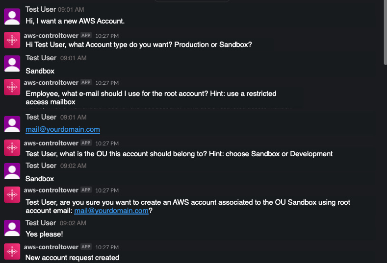
5.3 Choose to deploy and re-install the Slack App to your workspace and then access the ChatBot Application within your Slack workspace. If everything is successful, you can see a working Serverless ChatBot as shown below.

Slack Example

Conclusion and Cleanup

Conclusion

In this blog post, you have learned how to create a multi-environment CICD pipeline that builds a fully Serverless AWS account vending solution using an AI powered Amazon Lex bot integrated with AWS Control Tower Account Factory. This solution will help you enable standardized account vending on AWS through an easy way by exposing a ChatBot to your AWS consumers coming from various channels. This solution can be extended with AWS ServiceCatalog to allow to launch not just AWS accounts, but almost any AWS Service by using IaC (CloudFormation) templates provided through the CCoE Ops and Architecture teams.

Cleanup

For a proper cleanup, you can just go into AWS CloudFormation and choose the deployed Stacks and choose to “delete Stack”. If you incur issues while deleting, see below troubleshooting solutions for a fix. Also make sure you delete your integration Apps (e.g. Slack) for a full cleanup.

Troubleshooting

  1. An error occurred (BucketAlreadyOwnedByYou) when calling the CreateBucket operation: Your previous request to create the named bucket succeeded and you already own it.
    Solution: Make sure you use a distinct name for the S3 bucket used in this project, for the Amazon Lex Bot and the CICD pipeline
  2. When you delete and rollback of the CloudFormation stacks and you get an error (Code: 409; Error Code: BucketNotEmpty).
    Solution: Delete the S3 build bucket and its content “delete permanently” and then delete the associated CloudFormation stack that has created the CICD pipeline.

Automate Amazon Redshift Cluster management operations using AWS CloudFormation

Post Syndicated from Anusha Challa original https://aws.amazon.com/blogs/big-data/automate-amazon-redshift-cluster-management-operations-using-aws-cloudformation/

Amazon Redshift is the fastest and most widely used cloud data warehouse. Tens of thousands of customers run business-critical workloads on Amazon Redshift. Amazon Redshift offers many features that enable you to build scalable, highly performant, cost-effective, and easy-to-manage workloads. For example, you can scale an Amazon Redshift cluster up or down based on your workload requirements, pause clusters when not in use to suspend on-demand billing, and enable relocation. You can automate these management activities either using the Amazon Redshift API, AWS Command Line Interface (AWS CLI), or AWS CloudFormation.

AWS CloudFormation helps you model and set up your AWS resources so that you can spend less time managing those resources and more time focusing on your applications that run in AWS. You create a template that describes all the AWS resources that you want, and AWS CloudFormation takes care of provisioning and configuring those resources for you.

In this post, we walk through how to use AWS CloudFormation to automate some of the most common Amazon Redshift cluster management operations:

  • Create an Amazon Redshift cluster via the following methods:
    • Restore a cluster from a snapshot
    • Create an encrypted Amazon Redshift cluster
  • Perform cluster management operations:
    • Pause or resume a cluster
    • Perform elastic resize or classic resize
    • Add or remove Identity and Access Management (IAM) roles to cluster permissions
    • Rotate encryption keys
    • Modify snapshot retention period for automated and manual snapshots
    • Enable or disable snapshot copy to another AWS Region
    • Create a parameter group with required workload management (WLM) configuration and associate it to the Amazon Redshift cluster
    • Enable concurrency scaling by modifying WLM configuration
    • Enable or disable audit logging

For a complete list of operations that you can automate using AWS CloudFormation, see Amazon Redshift resource type reference.

Benefits of using CloudFormation templates

Many of our customers build fully automated production environments and use AWS CloudFormation to aid automation. AWS CloudFormation offers an easy way to create and manage AWS Infrastructure, by treating infrastructure as code. CloudFormation templates create infrastructure resources in a group called a stack, and allow you to define and customize all components. CloudFormation templates introduce the ability to implement version control, and the ability to quickly and reliably replicate your infrastructure. This significantly simplifies your continuous integration and continuous delivery (CI/CD) pipelines and keeps multiple environments in sync. The CloudFormation template becomes a repeatable, single source of truth for your infrastructure. You can create CloudFormation templates in YAML and JSON formats. The templates provided in this post use YAML format. Amazon Redshift clusters are one of the resources that you can provision and manage using AWS CloudFormation.

Create an Amazon Redshift cluster using AWS CloudFormation

With AWS CloudFormation, you can automate Amazon Redshift cluster creation. In this section, we describe two additional ways of creating Amazon Redshift clusters: by restoring from an existing snapshot or creating using default options. In the next section, we describe how you can manage the lifecycle of a cluster by performing cluster management operations using AWS CloudFormation.

Restore an Amazon Redshift cluster from a snapshot

Snapshots are point-in-time backups of a cluster. Amazon Redshift periodically takes automated snapshots of the cluster. You can also take a snapshot manually any time. A snapshot contains data from any databases that are running on the cluster. Snapshots enable data protection, and you can also use them to build new environments to perform application testing, data mining, and more. When you start a new development or enhancement project, you may want to build a new Amazon Redshift cluster that has the same code and data as that of your production, so you can develop and test your code there before deploying it. To do this, create the new cluster by restoring from your production cluster’s snapshot.

You can use AWS CloudFormation to automate the restore operation. If you have multiple projects with different timelines or requirements, you can build multiple Amazon Redshift clusters in an automatic and scalable fashion using AWS CloudFormation.

To create a new Amazon Redshift cluster by restoring from an existing snapshot, create a CloudFormation stack using a CloudFormation template that has the AWS::Redshift::Cluster resource with the following mandatory properties:

  • SnapshotIdentifier – The name of the snapshot from which to create the new cluster
  • ClusterIdentifier – A unique identifier of your choice for the cluster
  • NodeType – The node type to be provisioned for the cluster
  • ClusterType – The type of the cluster, either single-node or multi-node (recommended for production workloads)
  • NumberofNodes – The number of compute nodes in the cluster
  • DBName – The name of the first database to be created in the new cluster
  • MasterUserName – The user name associated with the admin user account for the cluster that is being created
  • MasterUserPassword – The password associated with the admin user account for the cluster that is being created

The following is a sample CloudFormation template that restores a snapshot with identifier cfn-blog-redshift-snapshot and creates a two-node Amazon Redshift cluster with identifier cfn-blog-redshift-cluster and node type ra3.4xlarge:

AWSTemplateFormatVersion: 2010-09-09
Description: Redshift CFN Blog Cluster Stack
Parameters:
  MasterUserPasswordParam:
    NoEcho: true
    Type: String
    Description: Enter Master User Password 
Resources:
  RedshiftCluster:
    Type: "AWS::Redshift::Cluster"
    Properties:
      SnapshotIdentifier: "cfn-blog-redshift-snapshot"
      ClusterIdentifier: "cfn-blog-redshift-cluster"
      ClusterType: "multi-node"
      NodeType: "ra3.4xlarge"
      NumberOfNodes: "2"
      DBName: "dev"
      MasterUsername: "username"
      Encrypted: true
      MasterUserPassword: !Ref MasterUserPasswordParam
Outputs:
  ClusterName:
    Value: !Ref RedshiftCluster

Create an encrypted Amazon Redshift cluster

You can enable database encryption for your clusters to protect data at rest.

Use the following sample CloudFormation template to create an encrypted Amazon Redshift cluster. This template has basic properties only to make this walkthrough easy to understand. For your production workload, we recommend following the best practices as described in the post Automate Amazon Redshift cluster creation using AWS CloudFormation.

AWSTemplateFormatVersion: 2010-09-09
Description: Redshift CFN Blog Cluster Stack
Parameters:
  MasterUserPasswordParam:
    NoEcho: true
    Type: String
    Description: Enter Master User Password. Must be 8-64 characters long. Must contain at least one uppercase letter, one lowercase letter and one number. Can be any printable ASCII character except “/”, ““”, or “@”.
Resources:
  RedshiftCluster:
    Type: "AWS::Redshift::Cluster"
    Properties:
      ClusterIdentifier: "cfn-blog-redshift-cluster"
      ClusterType: "multi-node"
      NodeType: "ra3.4xlarge"
      NumberOfNodes: "2"
      DBName: "dev"
      MasterUsername: "username"
      Encrypted: true
      MasterUserPassword: !Ref MasterUserPasswordParam
Outputs:
  ClusterName:
    Value: !Ref RedshiftCluster

In AWS CloudFormation, create a stack using this template. When the creation of CloudFormation stack is complete, you can see a new encrypted Amazon Redshift cluster called cfn-blog-redshift-cluster. For the rest of this post, we use this CloudFormation template as the base and explore how to modify the template to perform various Amazon Redshift management operations.

To create a new CloudFormation stack that uses the preceding template via the AWS CloudFormation console, complete the following steps:

  1. On the AWS CloudFormation console, choose Create Stack.
  2. On the drop-down menu, choose With new resources (standard).
  3. For Prepare template, choose Template is ready.
  4. For Specify template, choose Upload a template file.
  5. Save the provided CloudFormation template in a .yaml file and upload it.
  6. Choose Next.
  7. Enter a name for the stack. For this post, we use RedshiftClusterStack-CFNBlog.
  8. Choose Next.
  9. Choose Next again.
  10. Choose Create Stack.

To create the CloudFormation stack using the AWS CLI, run the following command:

aws cloudformation create-stack \
--stack-name RedshiftClusterStack-CFNBlog \
--template-body <<CloudFormation template’s file name>> \

The status of the stack changes to CREATE_IN_PROGRESS. After the Amazon Redshift cluster is created, the status changes to CREATE_COMPLETE. Navigate to the Amazon Redshift console to verify that the cluster is created and the status is Available.

Perform cluster management operations

Amazon Redshift customers have the flexibility to perform various cluster operations to implement workload security, perform cost-optimization, and manage scale. Often, we see our customers perform these operations in all their environments, such as DEV, QA, and PROD, to keep them in sync. You can automate these operations using CloudFormation stack updates by updating the CloudFormation template you used to create the cluster.

To perform these management operations using CloudFormation stack updates, you can create your initial CloudFormation stack in one of the two ways:

  • If your cluster isn’t already created, you can create it using AWS CloudFormation.
  • If you have an existing cluster, create a CloudFormation stack with the using existing resources option. Provide a template of the existing cluster and have a CloudFormation stack associated with the resource.

Each subsequent cluster management operation is an update to the base CloudFormation stack’s template. CloudFormation stack updates enable you to make changes to a stack’s resources by performing an update to the stack instead of deleting it and creating a new stack. Update to either add, modify, or remove relevant property values in the AWS::Redshift::Cluster resource to trigger the respective Amazon Redshift cluster management operation. AWS CloudFormation compares the changes you submit with the current state of your stack and applies only the changes. For a summary of the update workflow, see How does AWS CloudFormation work?

The following steps describe how to perform a CloudFormation stack update on the RedshiftClusterStack-CFNBlog stack that you created in the previous section.

  1. On the AWS CloudFormation console, choose Stacks in the navigation pane.
  2. Choose the stack you want to update (for this post, RedshiftClusterStack-CFNBlog).
  3. Choose Update.
  4. In the Prerequisite – Prepare template section, choose Replace current template.
  5. For Specify template, choose Upload a template file.
  6. Make changes to your current CloudFormation template based on the operation you wish to perform on the Amazon Redshift cluster.
  7. Save the updated CloudFormation template .yaml file and upload it.
  8. Choose Next.
  9. Choose Next again.
  10. Choose Next again.
  11. Choose Update Stack.

To update CloudFormation stack using the AWS CLI, run the following command:

aws cloudformation update-stack \
--stack-name RedshiftClusterStack-CFNBlog \
--template-body <<Updated CloudFormation template’s file name>> \

In this section, we look at some AWS CloudFormation properties available for Amazon Redshift clusters and dive deep to understand how to update the CloudFormation template and add, remove, or modify these properties to automate some of the most common cluster management operations. We use the RedshiftClusterStack-CFNBlog stack that you created in the previous section as an example.

Pause or resume cluster

If an Amazon Redshift cluster isn’t being used for a certain period of time, you can pause it easily and suspend on-demand billing. For example, you can suspend on-demand billing on a cluster that is used for development when it’s not in use. While the cluster is paused, you’re only charged for the cluster’s storage. This adds significant flexibility in managing operating costs for your Amazon Redshift clusters. You can resume a paused cluster when you’re ready to use it. To pause a cluster, update the cluster’s current CloudFormation stack template to add a new property called ResourceAction with the value pause-cluster. To pause the cluster created using the RedshiftClusterStack-CFNBlog stack, you can perform a stack update and use the following updated CloudFormation template:

AWSTemplateFormatVersion: 2010-09-09
Description: Redshift CFN Blog Cluster Stack
Parameters:
  MasterUserPasswordParam:
    NoEcho: true
    Type: String
    Description: Enter Master User Password
Resources:
  RedshiftCluster:
    Type: "AWS::Redshift::Cluster"
    Properties:
      #Added this property to pause cluster
      ResourceAction: "pause-cluster"
      ClusterIdentifier: "cfn-blog-redshift-cluster"
      ClusterType: "multi-node"
      NodeType: "ra3.4xlarge"
      NumberOfNodes: "2"
      DBName: "dev"
      MasterUsername: "username"
      Encrypted: true
      MasterUserPassword: !Ref MasterUserPasswordParam
Outputs:
  ClusterName:
    Value: !Ref RedshiftCluster

Follow the steps in the previous section to update the stack. When the stack update operation is in progress, the cluster’s status changes from Available to Modifying, Pausing.

When the stack update is complete, the cluster’s status changes to Paused.

When you’re ready to use the cluster, you can resume it. To resume the cluster, update the cluster’s current CloudFormation stack template and change the value of the ResourceAction property to resume-cluster. You can use the following template to perform a stack update operation to resume the cluster created using the RedshiftClusterStack-CFNBlog stack:

AWSTemplateFormatVersion: 2010-09-09
Description: Redshift CFN Blog Cluster Stack
Parameters:
  MasterUserPasswordParam:
    NoEcho: true
    Type: String
    Description: Enter Master User Password
Resources:
  RedshiftCluster:
    Type: "AWS::Redshift::Cluster"
    Properties:
      #Added this property to resume cluster
      ResourceAction: "resume-cluster"
      ClusterIdentifier: "cfn-blog-redshift-cluster"
      ClusterType: "multi-node"
      NodeType: "ra3.4xlarge"
      NumberOfNodes: "2"
      DBName: "dev"
      MasterUsername: "username"
      Encrypted: true
      MasterUserPassword: !Ref MasterUserPasswordParam
Outputs:
  ClusterName:
    Value: !Ref RedshiftCluster

Follow the steps in the previous section to update the stack. When the stack update is in progress, the cluster’s status changes from Paused to Modifying, Resuming.

When the stack update is complete, the cluster’s status changes to Available.

Perform elastic resize or classic resize

Data warehouse workloads often have changing needs. You may add a new line of business and thereby ingest more data into the data warehouse, or you may have a new analytics application for your business users and add new ETL processes to support it. When your compute requirements change due to changing needs, you can resize your Amazon Redshift cluster using one of the following approaches:

  • Elastic resize – This changes the node type, number of nodes, or both. Typically, it completes within 10–15 minutes when adding or removing nodes of the same type. Cross-instance elastic resize can take up to 45 minutes. We recommend using elastic resize whenever possible, because it completes much more quickly than classic resize. Elastic resize has some growth and reduction limits on the number of nodes.
  • Classic resize – You can also use classic resize to change the node type, number of nodes, or both. We recommend this option only when you’re resizing to a configuration that isn’t available through elastic resize, because it takes considerably more time depending on your data size.

You can automate both elastic resize and classic resize operations on Amazon Redshift clusters using AWS CloudFormation. The default resize operation when initiated using a CloudFormation stack update is elastic resize. If elastic resize isn’t possible for your configuration, AWS CloudFormation throws an error. You can force the resize operation to be classic resize by specifying the value of the property Classic to Boolean true in the CloudFormation template provided in the update stack operation. If you don’t provide this parameter or set the value to false, the resize type is elastic. To initiate the resize operation, update the cluster’s current CloudFormation stack template and change the value of NodeType and NumberOfNodes properties as per your requirement.

To perform an elastic resize from the initial two-node RA3 4xlarge configuration to NumberOfNodes:2 and NodeType:ra3.16xlarge configuration on the Amazon Redshift cluster cfn-blog-redshift-cluster, you can update the current template of the RedshiftClusterStack-CFNBlog stack as shown in the following CloudFormation template:

AWSTemplateFormatVersion: 2010-09-09
Description: Redshift CFN Blog Cluster Stack
Parameters:
  MasterUserPasswordParam:
    NoEcho: true
    Type: String
    Description: Enter Master User Password
Resources:
  RedshiftCluster:
    Type: "AWS::Redshift::Cluster"
    Properties:
      ResourceAction: "resume-cluster"
      ClusterIdentifier: "cfn-blog-redshift-cluster"
      ClusterType: "multi-node"
      #Modified the below 2 properties to perform elastic resize
      NodeType: "ra3.16xlarge"
      NumberOfNodes: "2"
      DBName: "dev"
      MasterUsername: "username"
      Encrypted: true
      MasterUserPassword: !Ref MasterUserPasswordParam
Outputs:
  ClusterName:
    Value: !Ref RedshiftCluster

Alternatively, if you want to force this resize to be a classic resize, use the following CloudFormation template to update the RedshiftClusterStack-CFNBlog stack. This template has an additional property, Classic with Boolean value true, to initiate classic resize, in addition to having updated NodeType and NumberOfNodes properties.

AWSTemplateFormatVersion: 2010-09-09
Description: Redshift CFN Blog Cluster Stack
Parameters:
  MasterUserPasswordParam:
    NoEcho: true
    Type: String
    Description: Enter Master User Password
Resources:
  RedshiftCluster:
    Type: "AWS::Redshift::Cluster"
    Properties:
      ResourceAction: "resume-cluster"
      ClusterIdentifier: "cfn-blog-redshift-cluster"
      ClusterType: "multi-node"
      #Modified the below 3 properties to perform classic resize
      NodeType: "ra3.16xlarge"
      NumberOfNodes: "2"
      Classic: true
      DBName: "dev"
      MasterUsername: "username"
      Encrypted: true
      MasterUserPassword: !Ref MasterUserPasswordParam
Outputs:
  ClusterName:
    Value: !Ref RedshiftCluster

Follow the steps earlier in this post to update the stack. For both elastic resize and classic resize, when the stack update is in progress, the cluster’s status changes from Available to Resizing.

Add or remove IAM roles to cluster permissions

Your Amazon Redshift cluster needs permissions to access other AWS services on your behalf. For the required permissions, add IAM roles to cluster permissions. You can add up to 10 IAM roles. For instructions on creating roles, see Create an IAM role.

To add IAM roles to the cluster, update the cluster’s current CloudFormation stack template and add the IamRoles property with a list of IAM roles you want to add. For example, to add IAM roles cfn-blog-redshift-role-1 and cfn-blog-redshift-role-2 to the cluster cfn-blog-redshift-cluster, you can update the RedshiftClusterStack-CFNBlog stack using the following CloudFormation template. In this template, the new array property IamRoles has been added with values cfn-blog-redshift-role-1 and cfn-blog-redshift-role-2.

AWSTemplateFormatVersion: 2010-09-09
Description: Redshift CFN Blog Cluster Stack
Parameters:
  MasterUserPasswordParam:
    NoEcho: true
    Type: String
    Description: Enter Master User Password
Resources:
  RedshiftCluster:
    Type: "AWS::Redshift::Cluster"
    Properties:
      ResourceAction: "resume-cluster"
      ClusterIdentifier: "cfn-blog-redshift-cluster"
      ClusterType: "multi-node"
      NodeType: "ra3.4xlarge"
      NumberOfNodes: "2"
      #Added IAMRoles property with ARNs for 2 roles
      IamRoles: [
                    !Sub "arn:${AWS::Partition}:iam::${AWS::AccountId}:role/cfn-blog-redshift-role-1",
                    !Sub "arn:${AWS::Partition}:iam::${AWS::AccountId}:role/cfn-blog-redshift-role-2"
                ]
      DBName: "dev"
      MasterUsername: "username"
      Encrypted: true
      MasterUserPassword: !Ref MasterUserPasswordParam
Outputs:
  ClusterName:
    Value: !Ref RedshiftCluster

Now, if you want to remove the IAM role cfn-blog-redshift-role-2 from the cfn-blog-redshift-cluster cluster, you can perform another CloudFormation stack update on RedshiftClusterStack-CFNBlog using the following CloudFormation template. This template contains only those IAM roles you want to retain.

AWSTemplateFormatVersion: 2010-09-09
Description: Redshift CFN Blog Cluster Stack
Parameters:
  MasterUserPasswordParam:
    NoEcho: true
    Type: String
    Description: Enter Master User Password
Resources:
  RedshiftCluster:
    Type: "AWS::Redshift::Cluster"
    Properties:
      ResourceAction: "resume-cluster"
      ClusterIdentifier: "cfn-blog-redshift-cluster"
      ClusterType: "multi-node"
      NodeType: "ra3.4xlarge"
      NumberOfNodes: "2"
      #Updated IAMRoles property to remove role-2
      IamRoles: [
                    !Sub "arn:${AWS::Partition}:iam::${AWS::AccountId}:role/cfn-blog-redshift-role-1"
                ]
      DBName: "dev"
      MasterUsername: "username"
      Encrypted: true
      MasterUserPassword: !Ref MasterUserPasswordParam
Outputs:
  ClusterName:
    Value: !Ref RedshiftCluster

Follow the steps earlier in this post to update the stack. When the stack update is in progress, the cluster’s status changes from Available to Available, Modifying.

Navigate to cluster’s properties tab and the Cluster Permissions section to validate that the IAM roles were associated to the cluster after the stack update is complete.

Rotate encryption keys on the cluster

You can enable database encryption for your Amazon Redshift clusters to protect data at rest. You can rotate encryption keys using AWS CloudFormation. To rotate encryption keys, update the base CloudFormation template to add the RotateEncryptionKey property and set it to Boolean true. For example, you can use the following CloudFormation template to rotate the encryption key for cfn-blog-redshift-cluster by performing an update on the CloudFormation stack RedshiftClusterStack-CFNBlog:

AWSTemplateFormatVersion: 2010-09-09
Description: Redshift CFN Blog Cluster Stack
Parameters:
  MasterUserPasswordParam:
    NoEcho: true
    Type: String
    Description: Enter Master User Password
Resources:
  RedshiftCluster:
    Type: "AWS::Redshift::Cluster"
    Properties:
      ResourceAction: "resume-cluster"
      ClusterIdentifier: "cfn-blog-redshift-cluster"
      ClusterType: "multi-node"
      NodeType: "ra3.4xlarge"
      NumberOfNodes: "2"
      #Added RotateEncryptionKey property
      RotateEncryptionKey: true
      DBName: "dev"
      MasterUsername: "username"
      Encrypted: true
      MasterUserPassword: !Ref MasterUserPasswordParam
Outputs:
  ClusterName:
    Value: !Ref RedshiftCluster

Follow the steps earlier in this post to update the stack. When the stack update is in progress, the cluster’s status changes from Available to Modifying, Rotating Keys. It takes approximately 2 minutes to rotate the encryption keys.

Modify the snapshot retention period for automated and manual snapshots

Amazon Redshift takes periodic automated snapshots of the cluster. By default, automated snapshots are retained for 24 hours. You can change the retention period of automated snapshots to 0–35 days. Amazon Redshift deletes automated snapshots at the end of a snapshot’s retention period, when you disable automated snapshots for the cluster or delete the cluster.

If you set the automated snapshot retention period to 0 days, the automated snapshots feature is disabled and any existing automated snapshots are deleted. Exercise caution before setting the automated snapshot retention period to 0.

You can take manual snapshots of the cluster any time. By default, manual snapshots are retained indefinitely, even after you delete the cluster. You can also specify the retention period when you create a manual snapshot. When the snapshot retention period is modified on automated snapshots, it applies to both existing and new automated snapshots. In contrast, when the snapshot retention period is modified on manual snapshots, it applies to new manual snapshots only.

To modify the retention period on snapshots, update your current cluster’s CloudFormation stack template. Add or update the AutomatedSnapshotRetentionPeriod property with an integer value (must be between 0–35) indicating the new retention period in days for automated snapshots, and the ManualSnapshotRetentionPeriod property with an integer value (must be between 1–3653) indicating the new retention period in days for manual snapshots.

The following CloudFormation template sets the AutomatedSnapshotRetentionPeriod to 7 days and ManualSnapshotRetentionPeriod to 90 days on cfn-blog-redshift-cluster when you update the current CloudFormation stack RedshiftClusterStack-CFNBlog:

AWSTemplateFormatVersion: 2010-09-09
Description: Redshift CFN Blog Cluster Stack
Parameters:
  MasterUserPasswordParam:
    NoEcho: true
    Type: String
    Description: Enter Master User Password
Resources:
  RedshiftCluster:
    Type: "AWS::Redshift::Cluster"
    Properties:
      ResourceAction: "resume-cluster"
      ClusterIdentifier: "cfn-blog-redshift-cluster"
      ClusterType: "multi-node"
      NodeType: "ra3.4xlarge"
      NumberOfNodes: "2"
      #Add snapshot retention properties
      AutomatedSnapshotRetentionPeriod: 7
      ManualSnapshotRetentionPeriod: 90
      DBName: "dev"
      MasterUsername: "username"
      Encrypted: true
      MasterUserPassword: !Ref MasterUserPasswordParam
Outputs:
  ClusterName:
    Value: !Ref RedshiftCluster

Enable or disable snapshot copies to another Region

You can configure your Amazon Redshift cluster to copy all new manual and automated snapshots for a cluster to another Region. You can choose how long to keep copied automated or manual snapshots in the destination Region. If the cluster is encrypted, because AWS Key Management Service (AWS KMS) keys are specific to a Region, you must configure a snapshot copy grant for a primary key in the destination Region. For information on how to create a snapshot copy grant, see Copying AWS KMS–encrypted snapshots to another AWS Region. Make sure that the snapshot copy grant is created before enabling snapshot copy to another Region using CloudFormation templates.

To enable snapshot copy to another Region, update your current cluster’s CloudFormation stack template and add or update the following properties:

  • DestinationRegion – Required to enable snapshot copy. It specifies the destination Region that snapshots are automatically copied to.
  • SnapshotCopyRetentionPeriod – Optional. Modifies the number of days to retain snapshots in the destination Region. If this property is not specified, the retention period is the same as that of the source Region. By default, this operation only modifies the retention period of existing and new copied automated snapshots. To change the retention period of copied manual snapshots using this property, set the SnapshotCopyManual property to true.
  • SnapshotCopyManual – Indicates whether to apply the snapshot retention period to newly copied manual snapshots instead of automated snapshots. If you set this option, only newly copied manual snapshots have the new retention period.
  • SnapshotCopyGrantName – The name of the snapshot copy grant.

To copy snapshots taken from cfn-blog-redshift-cluster into the Region us-west-1 and to modify the retention period of the newly copied manual snapshots to 90 days, update the current CloudFormation stack RedshiftClusterStack-CFNBlog with the following CloudFormation template:

AWSTemplateFormatVersion: 2010-09-09
Description: Redshift CFN Blog Cluster Stack
Parameters:
  MasterUserPasswordParam:
    NoEcho: true
    Type: String
    Description: Enter Master User Password
Resources:
  RedshiftCluster:
    Type: "AWS::Redshift::Cluster"
    Properties:
      ResourceAction: "resume-cluster"
      ClusterIdentifier: "cfn-blog-redshift-cluster"
      ClusterType: "multi-node"
      NodeType: "ra3.4xlarge"
      NumberOfNodes: "2"
      #Add cross-region snapshot copy properties
      DestinationRegion: "us-west-1"
      SnapshotCopyGrantName: "cfn-blog-redshift-cross-region-snapshot-copy-grant"
      SnapshotCopyManual: true
      SnapshotCopyRetentionPeriod: 90
      DBName: "dev"
      MasterUsername: "username"
      Encrypted: true
      MasterUserPassword: !Ref MasterUserPasswordParam
Outputs:
  ClusterName:
    Value: !Ref RedshiftCluster

To disable cross-Region snapshot copy, update your current CloudFormation stack’s template and remove the properties DestinationRegion, SnapshotCopyRetentionPeriod, SnapshotCopyManual and SnapshotCopyGrantName.

Create a parameter group with required WLM configuration and assign it to an Amazon Redshift cluster

You can use AWS CloudFormation to create an Amazon Redshift parameter group and associate it to an Amazon Redshift cluster. If you don’t associate a parameter group, the default parameter group is assigned, which has the defaults for parameter values and WLM configuration. When you create a new parameter group, it also has the defaults for parameters, unless you override them. The following CloudFormation template overrides the default values for the require_ssl and wlm_json_configuration parameters. The WLM configuration is specified in JSON format. In this template, automatic WLM configuration is defined on cfn-blog-redshift-cluster with three queues: etl_queue, reporting_queue, and the default queue, with the following specifications:

  • Priority for etl_queue is set to highest. It’s configured to route all queries run by users belonging to the group named etl_group to etl_queue.
  • Priority for reporting_queue is set to normal. It’s configured to route all queries run by users belonging to any group name with the word report in it or any query having a query group with the word report in it to the reporting_queue.
  • The following three query monitoring rules are defined to protect reporting_queue from bad queries:
    • When query runtime is greater than 7,200 seconds (2 hours), the query is stopped.
    • If a query has a nested loop join with more than 1,000,000 rows, its priority is changed to lowest.
    • If any query consumes more than 50% CPU utilization, it is logged.
  • All other queries are routed to the default queue. Priority for default_queue is set to lowest.
  • The following three query monitoring rules are defined to protect the default queue from bad queries:
    • If a query has a nested loop join with more than 1,000,000 rows, it is stopped.
    • If a query has a large return set and is returning more than 1,000,000 rows, it is stopped.
    • If more than 10 GB spilled to disk for a query, it is stopped.
AWSTemplateFormatVersion: 2010-09-09
Description: Redshift CFN Blog Cluster Stack
Parameters:
  MasterUserPasswordParam:
    NoEcho: true
    Type: String
    Description: Enter Master User Password
Resources:
  #Add parameter group resource
  RedshiftClusterParameterGroup: 
    Type: "AWS::Redshift::ClusterParameterGroup"
    Properties: 
      Description: "CFNBlog-Redshift-Cluster-parameter-group"
      ParameterGroupFamily: "redshift-1.0"
      Parameters: 
        - 
          ParameterName: "require_ssl"
          ParameterValue: "true"
        -
          ParameterName: "wlm_json_configuration"
          ParameterValue: "[
                            {
                              \"name\":\"etl_queue\",
                              \"user_group\":[\"etl_user\"],
                              \"auto_wlm\":true,
                              \"queue_type\":\"auto\",
                              \"priority\":\"highest\"
                            },
                            {
                              \"name\":\"reporting_queue\",
                              \"user_group\":[\"%report%\"],
                              \"user_group_wild_card\":1,
                              \"query_group\":[\"%report%\"],
                              \"query_group_wild_card\":1,
                              \"auto_wlm\":true,
                              \"queue_type\":\"auto\",
                              \"priority\":\"normal\",
                              \"rules\":[
                                        {
                                          \"rule_name\":\"timeout_2hours\",
                                          \"predicate\":[
                                                        {
                                                          \"metric_name\":\"query_execution_time\",
                                                          \"operator\":\">\",\"value\":7200
                                                        }
                                                      ],
                                          \"action\":\"abort\"
                                        },
                                        {
                                          \"rule_name\":\"nested_loop_reporting\",
                                          \"action\":\"change_query_priority\",
                                          \"predicate\":[
                                                        {
                                                          \"metric_name\":\"nested_loop_join_row_count\",
                                                          \"operator\":\">\",\"value\":1000000
                                                        }
                                                      ],
                                          \"value\":\"lowest\"
                                        },
                                        {
                                          \"rule_name\":\"expensive_computation\",
                                          \"predicate\":[
                                                        {
                                                          \"metric_name\":\"query_cpu_usage_percent\",
                                                          \"operator\":\">\",\"value\":50
                                                        }
                                                      ],
                                          \"action\":\"log\"
                                        }
                                      ]
                            },
                            {
                              \"name\":\"Default queue\",
                              \"auto_wlm\":true,
                              \"priority\":\"lowest\",
                              \"rules\":[
                                        {
                                          \"rule_name\":\"nested_loop\",
                                          \"action\":\"abort\",
                                          \"predicate\":[
                                                        {
                                                          \"metric_name\":\"nested_loop_join_row_count\",
                                                          \"operator\":\">\",\"value\":1000000
                                                        }
                                                      ]
                                        },
                                        {
                                          \"rule_name\":\"large_return_set\",
                                          \"action\":\"abort\",
                                          \"predicate\":[
                                                        {
                                                          \"metric_name\":\"return_row_count\",
                                                          \"operator\":\">\",\"value\":1000000
                                                        }
                                                      ]
                                        },
                                        {
                                          \"rule_name\":\"large_spill_to_disk\",
                                          \"action\":\"abort\",
                                          \"predicate\":[
                                                        {
                                                          \"metric_name\":\"query_temp_blocks_to_disk\",
                                                          \"operator\":\">\",
                                                          \"value\":10000
                                                        }
                                                      ]
                                        }
                                      ]
                            },
                            {
                              \"short_query_queue\":true
                            }
                          ]"
  RedshiftCluster:
    Type: "AWS::Redshift::Cluster"
    Properties:
      ResourceAction: "resume-cluster"
      ClusterIdentifier: "cfn-blog-redshift-cluster"
      ClusterType: "multi-node"
      NodeType: "ra3.4xlarge"
      NumberOfNodes: "2"
      DBName: "dev"
      MasterUsername: "username"
      Encrypted: true
      MasterUserPassword: !Ref MasterUserPasswordParam
      #Add parameter to associate parameter group
      ClusterParameterGroupName: !Ref RedshiftClusterParameterGroup
Outputs:
  ClusterName:
    Value: !Ref RedshiftCluster

Enable concurrency scaling by modifying WLM configuration

Concurrency scaling is an autoscaling feature of Amazon Redshift that enables you to support virtually unlimited concurrent users. When you turn on concurrency scaling, Amazon Redshift automatically adds additional cluster capacity to process an increase in both read queries and write queries.

You can enable concurrency scaling at an individual WLM queue level. To enable concurrency scaling using AWS CloudFormation, update you current stack’s CloudFormation template and change the parameter value for wlm_json_configuration to add a property called concurrency_scaling and set its value to auto.

The following CloudFormation template sets concurrency scaling to auto on reporting_queue. It also overrides the value for the max_concurrency_scaling_clusters parameter from default 1 to 5.

AWSTemplateFormatVersion: 2010-09-09
Description: Redshift CFN Blog Cluster Stack
Parameters:
  MasterUserPasswordParam:
    NoEcho: true
    Type: String
    Description: Enter Master User Password
Resources:
  RedshiftClusterParameterGroup: 
    Type: "AWS::Redshift::ClusterParameterGroup"
    Properties: 
      Description: "CFNBlog-Redshift-Cluster-parameter-group"
      ParameterGroupFamily: "redshift-1.0"
      Parameters: 
        - 
          ParameterName: "require_ssl"
          ParameterValue: "true"
        #add parameter to change default value for max number of concurrency scaling clusters parameter
        - 
          ParameterName: "max_concurrency_scaling_clusters"
          ParameterValue: "5"
        #Updated wlm configuration to set concurrency_scaling to auto
        -
          ParameterName: "wlm_json_configuration"
          ParameterValue: "[
                            {
                              \"name\":\"etl_queue\",
                              \"user_group\":[\"etl_user\"],
                              \"auto_wlm\":true,
                              \"queue_type\":\"auto\",
                              \"priority\":\"highest\"
                            },
                            {
                              \"name\":\"reporting_queue\",
                              \"user_group\":[\"%report%\"],
                              \"user_group_wild_card\":1,
                              \"query_group\":[\"%report%\"],
                              \"query_group_wild_card\":1,
                              \"auto_wlm\":true,
                              \"queue_type\":\"auto\",
                              \"priority\":\"normal\",
                              \"concurrency_scaling\":\"auto\"
                            },
                            {
                              \"name\":\"Default queue\",
                              \"auto_wlm\":true,
                              \"priority\":\"lowest\"
                            },
                            {
                              \"short_query_queue\":true
                            }
                          ]"
  RedshiftCluster:
    Type: "AWS::Redshift::Cluster"
    Properties:
      ResourceAction: "resume-cluster"
      ClusterIdentifier: "cfn-blog-redshift-cluster"
      ClusterType: "multi-node"
      NodeType: "ra3.4xlarge"
      NumberOfNodes: "2"
      DBName: "dev"
      MasterUsername: "username"
      Encrypted: true
      MasterUserPassword: !Ref MasterUserPasswordParam
      ClusterParameterGroupName: !Ref RedshiftClusterParameterGroup
Outputs:
  ClusterName:
    Value: !Ref RedshiftCluster

Enable or disable audit logging

When you enable audit logging, Amazon Redshift creates and uploads the connection log, user log, and user activity logs to Amazon Simple Storage Service (Amazon S3). You can automate enabling and disabling audit logging using AWS CloudFormation. To enable audit logging, update the base CloudFormation template to add the LoggingProperties property with the following sub-properties:

  • BucketName – The name of an existing S3 bucket where the log files are to be stored.
  • S3KeyPrefix – The prefix applied to the log file names

Also update the parameter group to change the value of the enable_user_activity_logging parameter to true.

To enable audit logging on cfn-blog-redshift-cluster and deliver log files to BucketName: cfn-blog-redshift-cluster-audit-logs with the S3KeyPrefix:cfn-blog, update the current CloudFormation stack RedshiftClusterStack-CFNBlog with the following CloudFormation template:

AWSTemplateFormatVersion: 2010-09-09
Description: Redshift CFN Blog Cluster Stack
Parameters:
  MasterUserPasswordParam:
    NoEcho: true
    Type: String
    Description: Enter Master User Password
Resources:
  RedshiftClusterParameterGroup: 
    Type: "AWS::Redshift::ClusterParameterGroup"
    Properties: 
      Description: "CFNBlog-Redshift-Cluster-parameter-group"
      ParameterGroupFamily: "redshift-1.0"
      Parameters: 
        - 
          ParameterName: "require_ssl"
          ParameterValue: "true"
        - 
          ParameterName: "max_concurrency_scaling_clusters"
          ParameterValue: "5"
        #add parameter to enable user activity logging
        -
          ParameterName: "enable_user_activity_logging"
          ParameterValue: "true"
  RedshiftCluster:
    Type: "AWS::Redshift::Cluster"
    Properties:
      ResourceAction: "resume-cluster"
      ClusterIdentifier: "cfn-blog-redshift-cluster"
      ClusterType: "multi-node"
      NodeType: "ra3.4xlarge"
      NumberOfNodes: "2"
      DBName: "dev"
      MasterUsername: "username"
      Encrypted: true
      MasterUserPassword: !Ref MasterUserPasswordParam
      #Add LoggingProperties and its sub-properties
      LoggingProperties:
          BucketName: "cfn-blog-redshift-cluster-audit-logs"
          S3KeyPrefix: "cfn-blog/"
      ClusterParameterGroupName: !Ref RedshiftClusterParameterGroup
Outputs:
  ClusterName:
    Value: !Ref RedshiftCluster

Follow the steps earlier in this post to update the stack. To disable audit logging, update the cluster’s CloudFormation stack template and remove the LoggingProperties property.

Concurrent operations

You can perform multiple cluster management operations using a single CloudFormation stack update. For example, you can perform elastic resize and rotate encryption keys on the cfn-blog-redshift-cluster using the following CloudFormation template. This template updates the values for NodeType and NumberOfNodes, which results in an elastic resize operation, and also sets the RotateEncryptionKey parameter value to Boolean true, which results in the encryption key rotation.

AWSTemplateFormatVersion: 2010-09-09
Description: Redshift CFN Blog Cluster Stack
Parameters:
  MasterUserPasswordParam:
    NoEcho: true
    Type: String
    Description: Enter Master User Password
Resources:
  RedshiftCluster:
    Type: "AWS::Redshift::Cluster"
    Properties:
      ResourceAction: "resume-cluster"
      ClusterIdentifier: "cfn-blog-redshift-cluster"
      ClusterType: "multi-node"
      # Change Node type, number of nodes and rotate encryption
      NodeType: "ra3.16xlarge"
      NumberOfNodes: "2"
      RotateEncryptionKey: true
      DBName: "dev"
      MasterUsername: "username"
      Encrypted: true
      MasterUserPassword: !Ref MasterUserPasswordParam
Outputs:
  ClusterName:
    Value: !Ref RedshiftCluster

Conclusion

You have now learned how to automate management operations on Amazon Redshift clusters using AWS CloudFormation. For a full list of properties you can update using this process, see Properties. For more sample CloudFormation templates, see Amazon Redshift template snippets.


About the Authors

Anusha Challa is a Senior Analytics Specialist Solutions Architect at AWS. She has over a decade of experience in building large-scale data warehouses, both on-premises and in the cloud. She provides architectural guidance to our customers on end-to-end data warehousing implementations and migrations.

Shweta Yakkali is a Software Engineer for Amazon Redshift, where she works on developing features for Redshift Cloud infrastructure. She is passionate about innovations in cloud infrastructure and enjoys learning new technologies and building enhanced features for Redshift. She holds M.S in Computer Science from Rochester Institute of Technology, New York. Outside of work, she enjoys dancing, painting and playing badminton.

Zirui Hua is a Software Development Engineer for Amazon Redshift, where he works on developing next generation features for Redshift. His main focuses are on networking and proxy of database. Outside of work, he likes to play tennis and basketball.
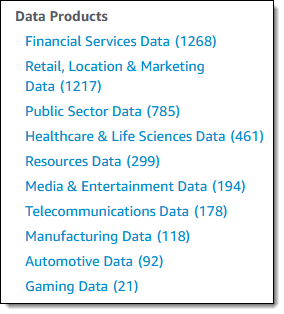
Compare different node types for your workload using Amazon Redshift

Post Syndicated from Manash Deb original https://aws.amazon.com/blogs/big-data/compare-different-node-types-for-your-workload-using-amazon-redshift/

Amazon Redshift is a fast, fully managed, widely popular cloud data warehouse that offers different node types to meet the flexible workload patterns of our customers. Amazon Redshift RA3 with managed storage is the newest instance type in Amazon Redshift, which allows you to scale and pay for compute and storage independently, and also allows advanced features like AQUA (Advanced Query Accelerator), cross-cluster data sharing, and cross-Availability Zone cluster relocation.

Many customers start their workload on Amazon Redshift with RA3 instances as their default choice, which currently offers three node sizes.

Node size vCPU RAM (GiB) Managed storage quota per node
ra3.xlplus 4 32 32 TB
ra3.4xlarge 12 96 128 TB
ra3.16xlarge 48 384 128 TB

A very common question we get from customers is “Which RA3 instance type and number of nodes should we choose for our workload?” In this post, we answer that question with the following two-step process:

  1. Use the Amazon Redshift sizing calculator on the Amazon Redshift console, which estimates your cluster configuration based on data size and data access frequency.
  2. Use the Amazon Redshift Node Configuration Comparison utility to find the right configuration for your cluster based on your query performance expectation for sequential or concurrently running queries. If you’re already using Amazon Redshift and want to migrate from your existing DC2 or DS2 instances to RA3, you may follow our recommendations on node count and type when upgrading. Before doing that, you can use the utility to evaluate the new cluster’s performance by replaying your past workloads too, which integrates with the Amazon Redshift Simple Replay utility to evaluate performance metrics for different Amazon Redshift configurations to meet your needs. We describe this utility in detail later in this post.

Amazon Redshift sizing calculator

The Amazon Redshift console provides the Help me choose option when you create a new Amazon Redshift cluster. This option allows you to get an estimate of your cluster configuration based on your data size and data access frequency. In this wizard, you need to provide the following information:

  • The compressed or uncompressed size of your total dataset
  • Whether your data is time-based:
    • If your data is time based, how many months of data does the data warehouse contain and how many months are frequently queried on that data
    • If your data is not time based, what percentage of data do your queries access frequently

Based on your response, you receive a recommended node configuration, as shown in the following screenshot.

You can use this recommendation to create your Amazon Redshift cluster and quickly get started with your workload to gain insights from your data in the Amazon Redshift data warehouse.

Amazon Redshift Node Configuration Comparison utility

If you have stringent service level agreements (SLAs) for query performance in your Amazon Redshift cluster or you want to explore different Amazon Redshift configurations based on the price/performance of your workload, you can use the Amazon Redshift Node Configuration Comparison utility. This utility helps evaluate performance of your queries using different Amazon Redshift cluster configurations in parallel and compares the end results to find the best cluster configuration that meets your need.

To perform this comparison, you can use the Amazon Redshift sizing calculator recommendations in the previous step as a benchmark and test other configurations with it in parallel to compare performance. If you’re migrating from DC2 or DS2 node types to RA3, you can use our recommendations on node count and type as a benchmark.

Solution overview

The solution uses AWS Step Functions, AWS Lambda, and AWS Batch to run an end-to-end automated orchestration to find the best Amazon Redshift configuration based on your price/performance requirements. We use an AWS CloudFormation template to deploy and run this solution in your AWS account. Along with other resources, this template creates an Amazon Simple Storage Service (Amazon S3) bucket to store all data and metadata related to this process. The following diagram shows the solution architecture.

You need to create a JSON file to provide the following input configurations for your test:

  • Amazon Redshift cluster configurations
  • DDL and load script (optional)
  • Amazon Redshift snapshot identifier (optional)
  • SQL script to conduct sequential and concurrency test (optional)
  • Amazon Redshift audit log location and simple replay time window (optional)

You need to store this file in an existing S3 bucket and then use the following CloudFormation template to deploy this solution. This solution uses AWS CloudFormation to automatically provision all the required resources in your AWS accounts. For more information, see Getting started with AWS CloudFormation.

Deploying the solution also initiates an iteration of this test by invoking a Step Functions state machine in your AWS account.

Prerequisites

If you’re already running an Amazon Redshift workload in production, you can use this solution to replay your past workload using the Amazon Redshift Simple Replay utility. This helps you conduct what-if analysis on Amazon Redshift and evaluate how your workload performs with different configurations. For example, you can use the tool to benchmark your actual workload on a new instance type like RA3, evaluate a new feature like AQUA, or assess different cluster configurations. It replays your workload with the same time interval between connections, transactions, and queries as the source. It also supports extract, transform, and load (ETL) workloads including COPY and UNLOAD statements. The Amazon Redshift Node Configuration Comparison utility uses Simple Replay to automate all these configuration tests. As a prerequisite to use Simple Replay, you need to enable audit logging and user-activity logging in your Amazon Redshift cluster.

Example use case

As an example, assume you have an existing Amazon Redshift cluster with two nodes of DC2.8XLarge instances. You want to evaluate migrating this cluster to RA3 node types. You used the Amazon Redshift sizing calculator in the previous step, which recommends using four nodes of RA3.4XL, but you also want to evaluate the performance with five nodes of RA3.4XL to meet your future growth demands. For that, you want to run five test queries sequentially as well as in 5 and 10 parallel sessions in all these clusters. You also want to replay the workload in the past hour on these clusters and compare their performance.

You also want to test your workload performance with concurrency scaling enabled in that clusters, which helps improve concurrent workloads with consistently fast query performance.

The following table summarizes the five cluster configurations that are evaluated as part of this test.

Node Type Number of Nodes Option
dc2.8xlarge 2 concurrency scaling – off
ra3.4xlarge 4 concurrency scaling – off
ra3.4xlarge 4 concurrency scaling – on
ra3.4xlarge 5 concurrency scaling – off
ra3.4xlarge 5 concurrency scaling – on

To perform this test using the Amazon Redshift Node Configuration Comparison utility, you provide these configurations in a JSON file and store it in an S3 bucket. You then use the provided CloudFormation template to deploy this utility, which performs the end-to-end performance testing in all the clusters in parallel and produces a performance evaluation summary, which can help you decide which configuration works best for you.

JSON file parameters

You need to provide a configuration JSON file to use this solution. The following table explains the input parameters for this JSON file.

JSON Parameter Allowed Values Description
SNAPSHOT_ID

N/A,

Amazon Redshift snapshot identifier

Enter the snapshot identifier if you want to create new Amazon Redshift clusters by restoring from a snapshot.
Snapshot identifier is mandatory if you’re using Simple Replay in this test to replay your past workload.
If you’re using this solution in a different AWS account, make sure to share your Amazon Redshift cluster snapshot with this account. For more information, see How do I copy an Amazon Redshift cluster to a different AWS account. Enter N/A if not applicable.
SNAPSHOT_ACCOUNT_ID

N/A,

AWS Account ID

The AWS account ID where the snapshot was created. Enter N/A if not applicable.
PARAMETER_GROUP_CONFIG_S3_PATH

N/A,

Amazon S3 URI

If you use a custom parameter group for this test, provide its Amazon S3 URI. You can get this JSON by running the following command in the AWS Command Line Interface (AWS CLI):

aws redshift describe-cluster-parameters --parameter-group-name your-custom-param-group --output json

Enter N/A if not applicable.

DDL_AND_COPY_SCRIPT_S3_PATH

N/A,

Amazon S3 URI

If you create tables and load data on them before performing the test, provide its Amazon S3 URI. Enter N/A if not applicable.
SQL_SCRIPT_S3_PATH

N/A,

Amazon S3 URI

If you run performance testing of your queries, provide the Amazon S3 URI of your script consisting of all your SQL commands. These commands should be deliminated by a semicolon (;). Enter N/A if not applicable. We recommend keeping only SELECT statements in this script path.
NUMBER_OF_PARALLEL_SESSIONS_LIST N/A, comma-separated numbers Enter comma-separated numbers to denote the number of parallel sessions in which you want to run the preceding script. Enter N/A if not applicable.
SIMPLE_REPLAY_LOG_LOCATION

N/A,

Amazon S3 URI

If you’re already running an Amazon Redshift workload and your cluster has audit logging enabled, provide the Amazon S3 URI of your Amazon Redshift audit logging location. If you’re using this solution in a different AWS account, copy these logs from your source clusters’ audit logging bucket to the S3 bucket in this account. Enter N/A if not applicable.
SIMPLE_REPLAY_EXTRACT_START_TIME N/A, time in ISO-8601 format If you’re using Simple Replay in this test to replay your past workload, provide the start time of that workload in ISO-8601 format (for example, 2021-01-26T21:41:16+00:00). Enter N/A if not applicable.
SIMPLE_REPLAY_EXTRACT_END_TIME N/A, time in ISO-8601 format If you’re using Simple Replay in this test to replay your past workload, provide the end time of that workload in ISO-8601 format (for example, 2021-01-26T21:41:16+00:00). Enter N/A if not applicable.
SIMPLE_REPLAY_EXTRACT_OVERWRITE_S3_PATH

N/A,

Amazon S3 URI

If you’re using Simple Replay and you want to use a custom extract.yaml file, provide its Amazon S3 URI. Enter N/A if not applicable.
SIMPLE_REPLAY_OVERWRITE_S3_PATH

N/A,

Amazon S3 URI

If you’re using Simple Replay and you want to use a custom replay.yaml file, provide its Amazon S3 URI. Enter N/A if not applicable.
AUTO_PAUSE

true,

false

Enter true if you want to automatically pause all except the first Amazon Redshift clusters created for this test, otherwise enter false.
CONFIGURATIONS JSON array with parameters NODE_TYPE, NUMBER_OF_NODES, WLM_CONFIG_S3_PATH Enter a JSON array mentioning your Amazon Redshift cluster configurations for which you want to perform this test. We explain the parameters in the three rows.
NODE_TYPE ra3.xlplus, ra3.4xlarge, ra3.16xlarge, dc2.large, dc2.8xlarge, ds2.xlarge, ds2.8xlarge The Amazon Redshift cluster node type that you want to run for this test.
NUMBER_OF_NODES a number between 1–128 The number of nodes for your Amazon Redshift cluster.
WLM_CONFIG_S3_PATH

N/A,

Amazon S3 URI

If you want to use custom workload management settings if you have different Amazon Redshift clusters, provide the Amazon S3 URI for that. Enter N/A if not applicable.

The following code is a sample configuration JSON file used to implement this example use case:

{
"SNAPSHOT_ID": "redshift-cluster-manual-snapshot",
"SNAPSHOT_ACCOUNT_ID": "123456789012",

"PARAMETER_GROUP_CONFIG_S3_PATH": "s3://node-config-compare-bucket/pg_config.json",

"DDL_AND_COPY_SCRIPT_S3_PATH": "s3://node-config-compare-bucket/ddl.sql",
"SQL_SCRIPT_S3_PATH":"s3://node-config-compare-bucket/test_queries.sql",
"NUMBER_OF_PARALLEL_SESSIONS_LIST": "1,5,10",

"SIMPLE_REPLAY_LOG_LOCATION":"s3://redshift-logging-xxxxxxxx/RSLogs/",
"SIMPLE_REPLAY_EXTRACT_START_TIME":"2021-08-28T11:15:00+00:00",
"SIMPLE_REPLAY_EXTRACT_END_TIME":"2021-08-28T12:00:00+00:00",

"SIMPLE_REPLAY_EXTRACT_OVERWRITE_S3_PATH":"N/A",
"SIMPLE_REPLAY_OVERWRITE_S3_PATH":"N/A",

"AUTO_PAUSE": true,

"CONFIGURATIONS": [
	{
	"NODE_TYPE": "dc2.8xlarge",
	"NUMBER_OF_NODES": "2",
	"WLM_CONFIG_S3_PATH": "s3://node-config-compare-bucket/source-wlm.json"
	},	
	{
	"NODE_TYPE": "ra3.4xlarge",
	"NUMBER_OF_NODES": "4",
	"WLM_CONFIG_S3_PATH": "s3://node-config-compare-bucket/source-wlm.json"
	},
	{
	"NODE_TYPE": "ra3.4xlarge",
	"NUMBER_OF_NODES": "4",
	"WLM_CONFIG_S3_PATH": "s3://node-config-compare-bucket/wlm-concurrency-scaling.json"
	},
{
	"NODE_TYPE": "ra3.4xlarge",
	"NUMBER_OF_NODES": "5",
	"WLM_CONFIG_S3_PATH": "s3://node-config-compare-bucket/source-wlm.json"
	},
{
	"NODE_TYPE": "ra3.4xlarge",
	"NUMBER_OF_NODES": "5",
	"WLM_CONFIG_S3_PATH": "s3://node-config-compare-bucket/ wlm-concurrency-scaling.json"
	}
]
}

Make sure to use same S3 bucket to store all your configurations for this test. For example, we use the S3 bucket node-config-compare-bucket to store all configuration scripts in the preceding JSON configuration. After you populate all the parameters in this JSON file, save the file in the same S3 bucket in your AWS account.

Deploy the solution using AWS CloudFormation

After you save the configuration JSON file in an S3 bucket, you can use the provided CloudFormation template to deploy this solution, which also initiates an iteration of this test. This template provisions the required AWS resources except for the Amazon Redshift clusters, which are created in the subsequent step by a Step Functions state machine. The following table lists the required parameters in the template.

CloudFormation Template Parameter Allowed Values Description
ConfigJsonS3Path Amazon S3 URI Enter the Amazon S3 URI where you stored your JSON configuration file from the previous step. The template grants access on this S3 bucket to the appropriate AWS resources created by this solution.
ClusterIdentifierPrefix Prefix of Amazon Redshift cluster identifiers Enter a valid string like rs to be used as the prefix of your Amazon Redshift cluster identifiers created by this solution.
PreExistingS3BucketToGrantRedshiftAccess

N/A,

Amazon S3 Bucket name

If you’re using Simple Replay, provide the Amazon Redshift audit logging bucket name so it can grant appropriate permissions to the AWS resources. You can also add an existing S3 bucket in same AWS Region, which can be accessed by Amazon Redshift. Enter N/A if not applicable.
GrantS3ReadOnlyAccessToRedshift

Yes,

No

If you’re using Simple Replay in the same AWS account as the source Amazon Redshift cluster, enter Yes for this parameter, which grants AmazonS3ReadOnlyAccess to the new Amazon Redshift clusters to replay copy statements within the account. Otherwise, enter No so you can’t replay copy statements if running on a different AWS account without manually configuring it.
SourceRedshiftClusterKMSKeyARN N/A, AWS KMS Key ARN Provide the AWS Key Management Service (AWS KMS) Key ARN (Amazon Resource Name) if your source Amazon Redshift cluster is encrypted (available on the stack Outputs tab). If using Simple Replay, you need to run extract and replay in the same AWS account if your source cluster is encrypted.
OnPremisesCIDR CIDR notation The IP range (CIDR notation) for your existing infrastructure to access the target and replica clusters from a SQL client. If unsure, enter your corporate desktop’s CIDR address. For instance, if your desktop’s IP address is 10.156.87.45, enter 10.156.87.45/32.
VPC VPC ID An existing Amazon Virtual Private Cloud (Amazon VPC) where you want to deploy the clusters and Amazon Elastic Compute Cloud (Amazon EC2) instances.
SubnetId Subnet ID An existing subnet within the VPC in which you deploy the Amazon Redshift clusters and AWS Batch compute environment.

Performance evaluation

The CloudFormation stack deployed in above step runs a Step Functions state machine to orchestrate the end-to-end workflow. Navigate to Step Functions in AWS Management Console to view the state machine deployed by this solution as shown in the following screenshot.

This state machine creates the Amazon Redshift clusters you defined in the configuration JSON file. Then, it runs the performance evaluation tests on these clusters. If you provided the value true for parameter AUTO_PAUSE in the input JSON file, it also pauses the Amazon Redshift clusters except for the first cluster. At the end, it unloads the performance comparison results to your Amazon S3 bucket.

The following screenshot shows the clusters that were created as part of this state machine run for our use case. The state machine automatically paused all clusters except the first one.

This state machine creates an external schema redshift_config_comparison and creates three external tables (comparison_stats, cluster_config, and pricing) in that schema to read the raw data created by this solution in an S3 bucket. Based on these external tables, it creates the views redshift_config_comparison_results and redshift_config_comparison_raw in the public schema of your Amazon Redshift clusters to compare their performance metrics. These objects can be accessed from any of the Amazon Redshift clusters created by this solution.

REDSHIFT_CONFIG_COMPARISON_RESULTS

This view provides the aggregated comparison summary of your Amazon Redshift clusters.

It provides the raw value and a percentage number for KPIs like total, mean, median, max query times, percentile-75, and percentile-90 to help you compare and find the most performant cluster based on the different cluster configurations. The test_type column in this view indicates if the test type was to replay your past workload using the Simple Replay utility or a concurrency test to run your queries in parallel with different concurrency numbers. We use the following query to view our outcome:

select * from public.redshift_config_comparison_results;

The following table summarizes the performance comparison results:

Test Type Cluster Identifier Total Query Time in Seconds Improved Total Query Time Mean Query Time in Seconds Improved Mean Query Time Median Query Time in Seconds Improved Median Query Time
simple-replay rs-dc2-8xlarge-2 98.75 0% 4.94 0% 5.11 0%
simple-replay rs-ra3-4xlarge-4 94.16 5% 4.71 5% 4.08 25%
simple-replay rs-ra3-4xlarge-4-cs 19.36 410% 0.97 409% 0.68 651%
simple-replay rs-ra3-4xlarge-5 16.21 509% 0.85 481% 0.65 686%
simple-replay rs-ra3-4xlarge-5-cs 14.66 574% 0.73 577% 0.6 752%
concurrency-1 rs-dc2-8xlarge-2 49.6 0% 9.92 0% 10.67 0%
concurrency-1 rs-ra3-4xlarge-4 45.2 10% 9.51 4% 10.3 4%
concurrency-1 rs-ra3-4xlarge-4-cs 45.2 10% 9.51 4% 10.4 3%
concurrency-1 rs-ra3-4xlarge-5 43.93 13% 8.79 13% 7.7 39%
concurrency-1 rs-ra3-4xlarge-5-cs 43.94 13% 8.78 13% 7.78 37%
concurrency-5 rs-dc2-8xlarge-2 24.8 0% 0.99 0% 0.79 8%
concurrency-5 rs-ra3-4xlarge-4 21.24 17% 0.85 16% 0.7 22%
concurrency-5 rs-ra3-4xlarge-4-cs 22.49 10% 0.9 10% 0.85 0%
concurrency-5 rs-ra3-4xlarge-5 19.73 26% 0.79 25% 0.72 19%
concurrency-5 rs-ra3-4xlarge-5-cs 18.73 32% 0.75 32% 0.72 18%
concurrency-10 rs-dc2-8xlarge-2 98.2 0% 1.96 0% 1.63 0%
concurrency-10 rs-ra3-4xlarge-4 85.46 15% 1.71 15% 1.58 3%
concurrency-10 rs-ra3-4xlarge-4-cs 88.09 11% 1.76 11% 1.59 2%
concurrency-10 rs-ra3-4xlarge-5 77.54 27% 1.55 26% 1.36 20%
concurrency-10 rs-ra3-4xlarge-5-cs 74.68 31% 1.49 32% 1.31 24%

Table 1: Summary of Performance Comparison Results

Based on these results, we can conclude that five nodes of RA3.4XLarge with concurrency scaling enabled was the best-performing configuration.

REDSHIFT_CONFIG_COMPARISON_RAW

This view provides the query-level comparison summary of your Amazon Redshift clusters. We use the following query:

select * from public.redshift_config_comparison_raw;

The following table shows the performance comparison results per query:

Query Hash Cluster Identifier Execution Time in Seconds Total Query Time in Seconds Compile Time in Seconds Queue Time in Seconds Username Query
0531f3b54885afb rs-dc2-8xlarge-2 2 7 5 0 awsuser 599
0531f3b54885afb rs-ra3-4xlarge-4 2 5 3 0 awsuser 510
0531f3b54885afb rs-ra3-4xlarge-4-cs 2 2 0 0 awsuser 499
0531f3b54885afb rs-ra3-4xlarge-5 1 6 4 0 awsuser 498
0531f3b54885afb rs-ra3-4xlarge-5-cs 1 1 0 0 awsuser 457
10ef3990f05c9f8 rs-dc2-8xlarge-2 0 0 0 0 awsuser 516
10ef3990f05c9f8 rs-ra3-4xlarge-4 0 0 0 0 awsuser 427
10ef3990f05c9f8 rs-ra3-4xlarge-4-cs 0 0 0 0 awsuser 423
10ef3990f05c9f8 rs-ra3-4xlarge-5 0 0 0 0 awsuser 412
10ef3990f05c9f8 rs-ra3-4xlarge-5-cs 0 0 0 0 awsuser 390

Table 2: Performance Comparison Per Query

Access permissions and security

To deploy this solution, you need administrator access on the AWS accounts where you plan to deploy the AWS CloudFormation resources for this solution.

The CloudFormation template provisions all the required resources using security best practices based on the principle of least privileges and hosts all resources within your account VPC. Access to the Amazon Redshift clusters is controlled with the CloudFormation template parameter OnPremisesCIDR, which you need to provide to allow on-premises users to connect to the new clusters using their SQL clients on the Amazon Redshift port.

Access permissions for all the resources are controlled using AWS Identity and Access Management (IAM) roles granting appropriate permissions to Amazon Redshift, AWS Lambda, AWS Step Functions, AWS Glue, and AWS Batch. Read and write access privileges are granted to the Amazon Redshift clusters and AWS Batch jobs on the S3 bucket created by the CloudFormation template so that it can read and update data and metadata configurations from that bucket. Read and write access privileges are also granted on the S3 bucket where the user configuration JSON file is uploaded.

Troubleshooting

There might be some rare instances in which failures occur in the state machine running this solution. To troubleshoot, refer to its logs, along with logs from the AWS Batch jobs in Amazon CloudWatch Logs. To view the AWS Batch logs, navigate to the Amazon CloudWatch console and choose Logs in the navigation pane. Find the log group with name <Your CloudFormation Stack Name>/log and choose the latest log streams.

To view the Step Functions logs, navigate to the state machine’s latest run on the Step Functions console and choose CloudWatch Logs for the failed Step Functions step.

After you fix the issue, you can restart the state machine by choosing New execution.

Clean up

Running this template in your AWS account may have some cost implications because it provisions new Amazon Redshift clusters, which may be charged as on-demand instances if you don’t have Reserved Instances. When you complete your evaluations, we recommend deleting the Amazon Redshift clusters to save cost. We also recommend pausing your clusters when not in use. If you don’t plan to run this test in future, you should also delete the CloudFormation stack, which deletes all the resources it created.

Conclusion

In this post, we walked you through the process to find the correct size of your Amazon Redshift cluster based on your performance requirements. You can start with our easy-to-use, out-of-the-box Amazon Redshift sizing calculator, or you can use the Amazon Redshift Node Configuration Comparison tool to evaluate the performance of your workload and find the best cluster configuration that meets your need.


About the Authors

Manash Deb is a Software Development Engineer in the AWS Directory Service team. He has worked on building end-to-end applications in different database and technologies for over 15 years. He loves to learn new technologies and solving, automating, and simplifying customer problems on AWS.

Ranjan Burman is a Analytics Specialist Solutions Architect at AWS. He specializes in Amazon Redshift and helps customers to build scalable analytical solutions. He has more than 13 years of experience in different database and data warehousing technologies. He is passionate about automating and solving customer problems with the use of cloud solutions.

Backwards-compatibility in Cloudflare Workers

Post Syndicated from Kenton Varda original https://blog.cloudflare.com/backwards-compatibility-in-cloudflare-workers/

Backwards-compatibility in
Cloudflare Workers

Backwards-compatibility in
Cloudflare Workers

Cloudflare Workers is our serverless platform that runs your code in 250+ cities worldwide.

On the Workers team, we have a policy:

A change to the Workers Runtime must never break an application that is live in production.

It seems obvious enough, but this policy has deep consequences. What if our API has a bug, and some deployed Workers accidentally depend on that bug? Then, seemingly, we can’t fix the bug! That sounds… bad?

This post will dig deeper into our policy, explaining why Workers is different from traditional server stacks in this respect, and how we’re now making backwards-incompatible changes possible by introducing “compatibility dates”.

TL;DR: Developers may now opt into backwards-incompatible fixes by setting a compatibility date.

Serverless demands strict compatibility

Workers is a serverless platform, which means we maintain the server stack for you. You do not have to manage the runtime version, you only manage your own code. This means that when we update the Workers Runtime, we update it for everyone. We do this at least once a week, sometimes more.

This means that if a runtime upgrade breaks someone’s application, it’s really bad. The developer didn’t make any change, so won’t be watching for problems. They may be asleep, or on vacation. If we want people to trust serverless, we can’t let this happen.

This is very different from traditional server platforms, where the developer maintains their own stack. For example, when a developer maintains a traditional VM-based server running Node.js applications, then the developer must decide exactly when to upgrade to a new version of Node.js. Careful developers do not upgrade Node.js 14 to Node.js 16 in production without testing first. They typically verify that their application works in a staging environment before going to production. A developer who doesn’t have time to spend testing each new version may instead choose to rely on a long-term support release, applying only low-risk security patches.

In the old world, if the Node.js maintainers decide to make a breaking change to an obscure API between releases, it’s OK. Downstream developers are expected to test their code before upgrading, and address any breakages. But in the serverless world, it’s not OK: developers have no control over when upgrades happen, therefore upgrades must never break anything.

But sometimes we need to fix things

Sometimes, we get things wrong, and we need to fix them. But sometimes, the fix would break people.

For example, in Workers, the fetch() function is used to make outgoing HTTP requests. Unfortunately, due to an oversight, our original implementation of fetch(), when given a non-HTTP URL, would silently interpret it as HTTP instead. For example, if you did fetch(“ftp://example.com”), you’d get the same result as fetch(“http://example.com”).

This is obviously not what we want and could lead to confusion or deeper bugs. Instead, fetch() should throw an exception in these cases. However, we couldn’t simply fix the problem, because a surprising number of live Workers depended on the behavior. For whatever reason, some Workers fetch FTP URLs and expect to get a result back. Perhaps they are fetching from sites that support both FTP and HTTP, and they arbitrarily chose FTP and it worked. Perhaps the fetches aren’t actually working, but changing a 404 error result into an exception would break things worse. When you have tens of thousands of new developers deploying applications every month, inevitably there’s always someone relying on any bug. We can’t “fix” the bug because it would break these applications.

The obvious solutions don’t work

Could we contact developers and ask them to fix their code?

No, because the problem is our fault, not the application developer’s, and the developer may not have time to help us fix our problems.

The fact that a Worker is doing something “wrong” — like using an FTP URL when they should be using HTTP — doesn’t necessarily mean the developer did anything wrong. Everyone writes code with bugs. Good developers rely on careful testing to make sure their code does what it is supposed to.

But what if the test only worked because of a bug in the underlying platform that caused it to do the right thing by accident? Well, that’s the platform’s fault. The developer did everything they could: they tested their code thoroughly, and it worked.

Developers are busy people. Nobody likes hearing that they need to drop whatever they are doing to fix a problem in code that they thought worked — especially code that has been working fine for years without anyone touching it. We think developers have enough on their plates already, we shouldn’t be adding more work.

Could we run multiple versions of the Workers Runtime?

No, for three reasons.

First, in order for edge computing to be effective, we need to be able to host a very large number of applications in each instance of the Workers Runtime. This is what allows us to run your code in hundreds of locations around the world at minimal cost. If we ran a separate copy of the runtime for each application, we’d need to charge a lot more, or deploy your code to far fewer locations. So, realistically it is infeasible for us to have different Workers asking for different versions of the runtime.

Second, part of the promise of serverless is that developers shouldn’t have to worry about updating their stack. If we start letting people pin old versions, then we have to start telling people how long they are allowed to do so, alerting people about security updates, giving people documentation that differentiates versions, and so on. We don’t want developers to have to think about any of that.

Third, this doesn’t actually solve the real problem anyway. We can easily implement multiple behaviors within the same runtime binary. But how do we know which behavior to use for any particular Worker?

Introducing Compatibility Dates

Going forward, every Worker is assigned a “compatibility date”, which must be a date in the past. The date is specified inside the project’s metadata (for Wrangler projects, in wrangler.toml). This metadata is passed to the Cloudflare API along with the application code whenever it is updated and deployed. A compatibility date typically starts out as the date when the Worker was first created, but can be updated from time to time.

# wrangler.toml
compatibility_date = "2021-09-20"

We can now introduce breaking changes. When we do, the Workers Runtime must implement both the old and the new behavior, and chooses behavior based on the compatibility date. Each time we introduce a new change, we choose a date in the future when that change will become the default. Workers with a later compatibility date will see the change; Workers with an older compatibility date will retain the old behavior.

A page in our documentation lists the history of breaking changes — and only breaking changes. When you wish to update your Worker’s compatibility date, you can refer to this page to quickly determine what might be affected, so that you can test for problems.

We will reserve the compatibility system strictly for changes which cannot be made without causing a breakage. We don’t want to force people to update their compatibility date to get regular updates, including new features, non-breaking bug fixes, and so on.

If you’d prefer never to update your compatibility date, that’s OK! Old compatibility dates are intended to be supported forever. However, if you are frequently updating your code, you should update your compatibility date along with it.

Acknowledgement

While the details are a bit different, we were inspired by Stripe’s API versioning, as well as the absolute promise of backwards compatibility maintained by both the Linux kernel system call API and the Web Platform implemented by browsers.

Security updates for Tuesday

Post Syndicated from original https://lwn.net/Articles/873307/rss

Security updates have been issued by Debian (redmine and strongswan), Fedora (containerd, fail2ban, grafana, moby-engine, and thunderbird), openSUSE (curl, firefox, glibc, kernel, libqt5-qtsvg, rpm, ssh-audit, systemd, and webkit2gtk3), Red Hat (389-ds:1.4, curl, kernel, kernel-rt, redis:5, and systemd), SUSE (util-linux), and Ubuntu (ardour, linux-azure, linux-azure-5.11, and strongswan).

Operating serverless at scale: Keeping control of resources – Part 3

Post Syndicated from James Beswick original https://aws.amazon.com/blogs/compute/operating-serverless-at-scale-keeping-control-of-resources-part-3/

This post is written by Jerome Van Der Linden, Solutions Architect.

In the previous part of this series, I provide application archetypes for developers to follow company best practices and include libraries needed for compliance. But using these archetypes is optional and teams can still deploy resources without them. Even if they use them, the templates can be modified. Developers can remove a layer, over-permission functions, or allow access to APIs without appropriate authorization.

To avoid this, you must define guardrails. Templates are good for providing guidance, best practices and to improve productivity. But they do not prevent actions like guardrails do. There are two kinds of guardrails:

  • Proactive: you define rules and permissions that avoid some specific actions.
  • Reactive: you define controls that detect if something happens and trigger notifications to alert someone or remediate actions.

This third part on serverless governance describes different guardrails and ways to implement them.

Implementing proactive guardrails

Proactive guardrails are often the most efficient but also the most restrictive. Be sure to apply them with caution as you could reduce developers’ agility and productivity. For example, test in a sandbox account before applying more broadly.

In this category, you typically find IAM policies and service control policies. This section explores some examples applied to serverless applications.

Controlling access through policies

Part 2 discusses Lambda layers, to include standard components and ensure compliance of Lambda functions. You can enforce the use of a Lambda layer when creating or updating a function, using the following policy. The condition checks if a layer is configured with the appropriate layer ARN:

{
    "Version": "2012-10-17",
    "Statement": [
        {
            "Sid": "ConfigureFunctions",
            "Effect": "Allow",
            "Action": [
                "lambda:CreateFunction",
                "lambda:UpdateFunctionConfiguration"
            ],
            "Resource": "*",
            "Condition": {
                "ForAllValues:StringLike": {
                    "lambda:Layer": [
                        "arn:aws:lambda:*:123456789012:layer:my-company-layer:*"
                    ]
                }
            }
        }
    ]
}

When deploying Lambda functions, some companies also want to control the source code integrity and verify it has not been altered. Using code signing for AWS Lambda, you can sign the package and verify its signature at deployment time. If the signature is not valid, you can be warned or even block the deployment.

An administrator must first create a signing profile (you can see it as a trusted publisher) using AWS Signer. Then, a developer can reference this profile in its AWS SAM template to sign the Lambda function code:

Resources:
  MyFunction:
    Type: AWS::Serverless::Function
    Properties:
      CodeUri: src/
      Handler: app.lambda_handler
      Runtime: python3.9
      CodeSigningConfigArn: !Ref MySignedFunctionCodeSigningConfig

  MySignedFunctionCodeSigningConfig:
    Type: AWS::Lambda::CodeSigningConfig
    Properties:
      AllowedPublishers:
        SigningProfileVersionArns:
          - arn:aws:signer:eu-central-1:123456789012:/signing-profiles/MySigningProfile
      CodeSigningPolicies:
        UntrustedArtifactOnDeployment: "Enforce"

Using the AWS SAM CLI and the --signing-profile option, you can package and deploy the Lambda function using the appropriate configuration. Read the documentation for more details.

You can also enforce the use of code signing by using a policy so that every function must be signed before deployment. Use the following policy and a condition requiring a CodeSigningConfigArn:

{
    "Version": "2012-10-17",
    "Statement": [
        {
            "Sid": "ConfigureFunctions",
            "Effect": "Allow",
            "Action": [
                "lambda:CreateFunction"
            ],
            "Resource": "*",
            "Condition": {
                "StringEquals": {
                    "lambda:CodeSigningConfigArn": "arn:aws:lambda:eu-central-1:123456789012:code-signing-config:csc-0c44689353457652"
                }
            }
        }
    ]
}

When using Amazon API Gateway, you may want to use a standard authorization mechanism. For example, a Lambda authorizer to validate a JSON Web Token (JWT) issued by your company identity provider. You can do that using a policy like this:

{
  "Version": "2012-10-17",
  "Statement": [
    {
      "Sid": "DenyWithoutJWTLambdaAuthorizer",
      "Effect": "Deny",
      "Action": [
        "apigateway:PUT",
        "apigateway:POST",
        "apigateway:PATCH"
      ],
      "Resource": [
        "arn:aws:apigateway:eu-central-1::/apis",
        "arn:aws:apigateway:eu-central-1::/apis/??????????",
        "arn:aws:apigateway:eu-central-1::/apis/*/authorizers",
        "arn:aws:apigateway:eu-central-1::/apis/*/authorizers/*"
      ],
      "Condition": {
        "ForAllValues:StringNotEquals": {
          "apigateway:Request/AuthorizerUri": 
            "arn:aws:apigateway:eu-central-1:lambda:path/2015-03-31/functions/arn:aws:lambda:eu-central-1:123456789012:function:MyCompanyJWTAuthorizer/invocations"
        }
      }
    }
  ]
}

To enforce the use of mutual authentication (mTLS) and TLS version 1.2 for APIs, use the following policy:

{
  "Version": "2012-10-17",
  "Statement": [
    {
      "Sid": "EnforceTLS12",
      "Effect": "Allow",
      "Action": [
        "apigateway:POST"
      ],
      "Resource": [
        "arn:aws:apigateway:eu-central-1::/domainnames",
        "arn:aws:apigateway:eu-central-1::/domainnames/*"
      ],
      "Condition": {
        "ForAllValues:StringEquals": {
            "apigateway:Request/SecurityPolicy": "TLS_1_2"
        }
      }
    }
  ]
}

You can apply other guardrails for Lambda, API Gateway, or another service. Read the available policies and conditions for your service here.

Securing self-service with permissions boundaries

When creating a Lambda function, developers must create a role that the function will assume when running. But by giving the ability to create roles to developers, one could elevate their permission level. In the following diagram, you can see that an admin gives this ability to create roles to developers:

Securing self-service with permissions boundaries

Developer 1 creates a role for a function. This only allows Amazon DynamoDB read/write access and a basic execution role for Lambda (for Amazon CloudWatch Logs). But developer 2 is creating a role with administrator permission. Developer 2 cannot assume this role but can pass it to the Lambda function. This role could be used to create resources on Amazon EC2, delete an Amazon RDS database or an Amazon S3 bucket, for example.

To avoid users elevating their permissions, define permissions boundaries. With these, you can limit the scope of a Lambda function’s permissions. In this example, an admin still gives the same ability to developers to create roles but this time with a permissions boundary attached. Now the function cannot perform actions that exceed this boundary:

Effect of permissions boundaries

The admin must first define the permissions boundaries within an IAM policy:

{
    "Version": "2012-10-17",
    "Statement": [
        {
            "Sid": "LambdaDeveloperBoundary",
            "Effect": "Allow",
            "Action": [
                "s3:List*",
                "s3:Get*",
                "logs:*",
                "dynamodb:*",
                "lambda:*"
            ],
            "Resource": "*"
        }
    ]
}

Note that this boundary is still too permissive and you should reduce and adopt a least privilege approach. For example, you may not want to grant the dynamodb:DeleteTable permission or restrict it to a specific table.

The admin can then provide the CreateRole permission with this boundary using a condition:

{
    "Version": "2012-10-17",
    "Statement": [
        {
            "Sid": "CreateRole",
            "Effect": "Allow",
            "Action": [
                "iam:CreateRole"
            ],
            "Resource": "arn:aws:iam::123456789012:role/lambdaDev*",
            "Condition": {
                "StringEquals": {
                    "iam:PermissionsBoundary": "arn:aws:iam::123456789012:policy/lambda-dev-boundary"
                }
            }
        }
    ]
}

Developers assuming a role lambdaDev* can create a role for their Lambda functions but these functions cannot have more permissions than defined in the boundary.

Deploying reactive guardrails

The principle of least privilege is not always easy to accomplish. To achieve it without this permission management burden, you can use reactive guardrails. Actions are allowed but they are detected and trigger a notification or a remediation action.

To accomplish this on AWS, use AWS Config. It continuously monitors your resources and their configurations. It assesses them against compliance rules that you define and can notify you or automatically remediate to non-compliant resources.

AWS Config has more than 190 built-in rules and some are related to serverless services. For example, you can verify that an API Gateway REST API is configured with SSL or protected by a web application firewall (AWS WAF). You can ensure that a DynamoDB table has back up configured in AWS Backup or that data is encrypted.

Lambda also has a set of rules. For example, you can ensure that functions have a concurrency limit configured, which you should. Most of these rules are part of the “Operational Best Practices for Serverless” conformance pack to ease their deployment as a single entity. Otherwise, setting rules and remediation can be done in the AWS Management Console or AWS CLI.

If you cannot find a rule for your use case in the AWS Managed Rules, you can find additional ones on GitHub or write your own using the Rule Development Kit (RDK). For example, enforcing the use of a Lambda layer for functions. This is possible using a service control policy but it denies the creation or modification of the function if the layer is not provided. You can use this policy in production but you may only want to notify the developers in their sandbox accounts or test environments.

By using the RDK CLI, you can bootstrap a new rule:

rdk create LAMBDA_LAYER_CHECK --runtime python3.9 \
--resource-types AWS::Lambda::Function \
--input-parameters '{"LayerArn":"arn:aws:lambda:region:account:layer:layer_name", "MinLayerVersion":"1"}'

It generates a Lambda function, some tests, and a parameters.json file that contains the configuration for the rule. You can then edit the Lambda function code and the evaluate_compliance method. To check for a layer:

LAYER_REGEXP = 'arn:aws:lambda:[a-z]{2}((-gov)|(-iso(b?)))?-[a-z]+-\d{1}:\d{12}:layer:[a-zA-Z0-9-_]+'

def evaluate_compliance(event, configuration_item, valid_rule_parameters):
    pkg = configuration_item['configuration']['packageType']
    if not pkg or pkg != "Zip":
        return build_evaluation_from_config_item(configuration_item, 'NOT_APPLICABLE',
                                                 annotation='Layers can only be used with functions using Zip package type')

    layers = configuration_item['configuration']['layers']
    if not layers:
        return build_evaluation_from_config_item(configuration_item, 'NON_COMPLIANT',
                                                 annotation='No layer is configured for this Lambda function')

    regex = re.compile(LAYER_REGEXP + ':(.*)')
    annotation = 'Layer ' + valid_rule_parameters['LayerArn'] + ' not used for this Lambda function'
    for layer in layers:
        arn = layer['arn']
        version = regex.search(arn).group(5)
        arn = re.sub('\:' + version + '$', '', arn)
        if arn == valid_rule_parameters['LayerArn']:
            if version >= valid_rule_parameters['MinLayerVersion']:
                return build_evaluation_from_config_item(configuration_item, 'COMPLIANT')
            else:
                annotation = 'Wrong layer version (was ' + version + ', expected ' + valid_rule_parameters['MinLayerVersion'] + '+)'

    return build_evaluation_from_config_item(configuration_item, 'NON_COMPLIANT',
                                             annotation=annotation)

You can find the complete source of this AWS Config rule and its tests on GitHub.

Once the rule is ready, use the command rdk deploy to deploy it on your account. To deploy it across multiple accounts, see the documentation. You can then define remediation actions. For example, automatically add the missing layer to the function or send a notification to the developers using Amazon Simple Notification Service (SNS).

Conclusion

This post describes guardrails that you can set up in your accounts or across the organization to keep control over deployed resources. These guardrails can be more or less restrictive according to your requirements.

Use proactive guardrails with service control policies to define coarse-grained permissions and block everything that must not be used. Define reactive guardrails for everything else to aid agility and productivity but still be informed of the activity and potentially remediate.

This concludes this series on serverless governance:

  • Standardization is an important aspect of the governance to speed up teams and ensure that deployed applications are operable and compliant with your internal rules. Use templates, layers, and other mechanisms to create shareable archetypes to apply these standards and rules at the enterprise level.
  • It’s important to keep visibility and control on your resources, to understand how your environment evolves and to be able to operate and act if needed. Tags and guardrails are helpful to achieve this and they should evolve as your maturity with the cloud evolves.

Find more SCP examples and all the AWS managed AWS Config rules in the documentation.

For more serverless learning resources, visit Serverless Land.

Using Machine Learning to Guess PINs from Video

Post Syndicated from Bruce Schneier original https://www.schneier.com/blog/archives/2021/10/using-machine-learning-to-guess-pins-from-video.html

Researchers trained a machine-learning system on videos of people typing their PINs into ATMs:

By using three tries, which is typically the maximum allowed number of attempts before the card is withheld, the researchers reconstructed the correct sequence for 5-digit PINs 30% of the time, and reached 41% for 4-digit PINs.

This works even if the person is covering the pad with their hands.

The article doesn’t contain a link to the original research. If someone knows it, please put it in the comments.

Slashdot thread.

Interview with Zabbix Summit Online 2021 speaker: Brian van Baekel

Post Syndicated from Jekaterina Sizova original https://blog.zabbix.com/interview-with-zabbix-summit-online-2021-speaker-brian-van-baekel/16174/

We continue to introduce you to the speakers of Zabbix Summit Online 2021. Our next guest is Brian van Baekel – a known Zabbix evangelist and trainer who has educated hundreds of students on all the nuances of working with our monitoring system.

Hi Brian, you are often seen on Zabbix Blog – mainly as the author of technical posts. Tell us, where did you get so much practical experience in using Zabbix?

Well, I started with Zabbix in 2013 and have been working with it ever since. During those years I’ve seen so many different environments. Each with their own challenges. Every challenge forces you to find a new creative solution and if you come across it often enough, you gain experience! I started Opensource ICT Solutions in early 2018 and the only thing we do is Zabbix. Either consultancy, training, or support worldwide, as long as it is Zabbix related. So that is even more experience that’s growing day by day as we’re serving exciting customers around the globe!

Is it true that you started using Zabbix with version 1.8? In your opinion, what are the most significant changes in the Zabbix functionality when comparing Zabbix then and now?

Yes that’s true, the first Zabbix version I started with was 1.8 and at that point I was not impressed with it, to say at least. After a few weeks, I saw the potential and started to enjoy the product more and more. After some time, we upgraded to a newer version of Zabbix where Low-Level Discovery was introduced… and wow! That was (and still is) one of the most powerful things.

In general, it’s not just one significant change that impresses me most as there are countless small and major improvements. In my opinion, it’s better to look at the product as a whole and the most significant change is how mature the product became during those years. If you really want me to name some significant changes, I must think about 3:

  • Low-Level Discovery
  • Tags
  • Dashboards
At the Zabbix Summit 2021, we will be introducing version 6.0 to the community in detail. Have you checked out the roadmap yet? Please tell us, what improvements are you most excited about?

To be honest I am not only checking the roadmap on a weekly basis but following the development rather closely to make sure we can anticipate what’s going to be introduced so we know what to advise customers.

As our customers are mainly on the Long Term Support versions, I am extremely happy that what was introduced in 5.2 and 5.4 will be available in a Long Term Support release. Regarding the new features, I am really excited about BSM(Business Level Monitoring) which will give us a comprehensive look at services instead of hosts and their metrics. That’s extremely valuable. The second thing that seems promising is HA. Although we’re building HA setups ourselves on a weekly basis it’s nice to have something natively available in the product.

Can you tell us about the speech you are going to give at the Zabbix Summit 2021?

Yes of course! So, as I mentioned, working as a Zabbix consultant and trainer, I see a lot of different environments where we have to solve various challenges. One of those challenges I came across is SNMP monitoring where the devices that had to be monitored were totally not able to handle all the SNMP requests. Luckily, they are sending traps. The art is to receive the traps and utilize them in such a way that you know the status of that device within seconds without just relying on the received trap solely. If you’re creative enough, Zabbix allows you to cater for that. So I’m going to explain why you want SNMP polling combined with SNMP traps and how to react on those traps so that you know the complete status of that device. The higher-level message of this talk is “Zabbix is flexible enough. The product is not the limit, your creativity is! Think out of the box and the sky is the limit”


Ransomware Attacks against Water Treatment Plants

Post Syndicated from Bruce Schneier original https://www.schneier.com/blog/archives/2021/10/ransomware-attacks-against-water-treatment-plants.html

According to a report from CISA last week, there were three ransomware attacks against water treatment plants last year.

WWS Sector cyber intrusions from 2019 to early 2021 include:

  • In August 2021, malicious cyber actors used Ghost variant ransomware against a California-based WWS facility. The ransomware variant had been in the system for about a month and was discovered when three supervisory control and data acquisition (SCADA) servers displayed a ransomware message.
  • In July 2021, cyber actors used remote access to introduce ZuCaNo ransomware onto a Maine-based WWS facility’s wastewater SCADA computer. The treatment system was run manually until the SCADA computer was restored using local control and more frequent operator rounds.
  • In March 2021, cyber actors used an unknown ransomware variant against a Nevada-based WWS facility. The ransomware affected the victim’s SCADA system and backup systems. The SCADA system provides visibility and monitoring but is not a full industrial control system (ICS).

Backblaze Files Registration Statement for Proposed Initial Public Offering

Post Syndicated from Backblaze original https://www.backblaze.com/blog/backblaze-files-registration-statement-for-proposed-initial-public-offering/

San Mateo, California, October 18, 2021 – Backblaze, Inc. today announced that it has publicly filed a registration statement on Form S-1 with the U.S. Securities and Exchange Commission (“SEC”) relating to a proposed initial public offering of its Class A common stock. The number of shares to be offered and the price range for the offering have not yet been determined. Backblaze intends to list its Class A common stock on the Nasdaq Global Market under the ticker symbol “BLZE.”

Oppenheimer & Co., William Blair and Raymond James will act as lead book-running managers for the proposed offering, with JMP Securities and B. Riley Securities acting as joint book-running managers. Lake Street will act as co-manager for the proposed offering.

The offering will be made only by means of a prospectus. Copies of the preliminary prospectus related to the offering may be obtained, when available, from Oppenheimer & Co. Inc., Attention: Syndicate Prospectus Department, 85 Broad St., 26th Floor, New York, NY 10004, by telephone at (212) 667-8055, or by email at [email protected]; William Blair & Company, L.L.C. Attention: Prospectus Department, 150 North Riverside Plaza, Chicago, IL 60606, or by telephone at (800) 621-0687 or by email at [email protected]; or Raymond James & Associates, Inc., 880 Carillon Parkway, St. Petersburg, FL 33716, email: [email protected], telephone: 800-248-8863.

A registration statement relating to these securities has been filed with the SEC but has not yet become effective. These securities may not be sold, nor may offers to buy be accepted, prior to the time the registration statement becomes effective. This press release shall not constitute an offer to sell or the solicitation of an offer to buy, nor shall there be any sale of these securities in any state or jurisdiction in which such offer, solicitation, or sale would be unlawful prior to registration or qualification under the securities laws of any such state or jurisdiction.

Investors:
James Kisner
Vice President of Investor Relations
ir@backblaze.com

Press Contact:
Patrick Thomas
Head of Publishing
press@backblaze.com

The post Backblaze Files Registration Statement for Proposed Initial Public Offering appeared first on Backblaze Blog | Cloud Storage & Cloud Backup.

The collective thoughts of the interwebz