Amazon Web Services (AWS) is pleased to announce the successful completion of our annual audit to renew our Payment Card Industry Three Domain Secure (PCI 3DS) certification. As part of this renewal, we have expanded the scope to include three additional AWS services and three additional AWS Regions:
This certification allows customers to use these services while maintaining PCI 3DS compliance, enabling innovation without compromising security. The full list of services can be found on the AWS Services in Scope by Compliance Program page.
The PCI 3DS compliance package includes two key components:
Attestation of Compliance (AOC) – demonstrates that AWS was successfully validated against the PCI 3DS standard.
AWS Responsibility Summary – provides guidance to help AWS customers understand their responsibility in developing and operating a highly secure environment on AWS for handling payment card data.
AWS was evaluated by Coalfire, a third-party Qualified Security Assessor (QSA).
This refreshed certification offers customers greater flexibility in deploying regulated workloads while reducing compliance overhead. Customers can access the PCI 3DS reports through AWS Artifact. This self-service portal provides on-demand access to AWS compliance reports, streamlining audit processes.
To learn more about our PCI programs and other compliance and security programs, see the AWS Compliance Programs page. As always, we value your feedback and questions; reach out to the AWS Compliance team through the Compliance Support page.
If you have feedback about this post, submit comments in the Comments section below. If you have questions about this post, contact AWS Support.
Amazon Web Services (AWS) is pleased to announce that three new AWS services have been added to the scope of our Payment Card Industry Data Security Standard (PCI DSS) certification:
This certification means that customers can use these services while maintaining PCI DSS compliance, enabling innovation without compromising security. The full list of services can be found on the AWS Services in Scope by Compliance Program page. The PCI DSS compliance package includes two key components:
Attestation of Compliance (AOC) – demonstrates that AWS was successfully validated against the PCI DSS standard.
AWS Responsibility Summary – provides guidance to help AWS customers understand their responsibility in developing and operating a highly secure environment on AWS for handling payment card data.
AWS was evaluated by Coalfire, a third-party Qualified Security Assessor (QSA).
This refreshed certification offers customers greater flexibility in deploying regulated workloads while reducing compliance overhead. Customers can access the PCI DSS reports through AWS Artifact. This self-service portal provides on-demand access to AWS compliance reports, streamlining audit processes.
To learn more about our PCI programs and other compliance and security programs, see the AWS Compliance Programs page. As always, we value your feedback and questions; reach out to the AWS Compliance team through the Compliance Support page.
If you have feedback about this post, submit comments in the Comments section below. If you have questions about this post, contact AWS Support.
Amazon Web Services (AWS) is pleased to announce enhancements to our Payment Card Industry (PCI) compliance portfolio, further empowering AWS customers to build and manage secure, compliant payment environments with greater ease and flexibility.
PCI Data Security Standard (DSS): Our latest AWS PCI DSS v4 Attestation of Compliance (AOC) is now available and includes six additional AWS services:
This expansion allows you to use these services while maintaining PCI DSS compliance, enabling innovation without compromising security. You can see the full list of services at AWS Services in Scope by Compliance Program.
AWS CloudHSM: Manage your encryption keys on FIPS 140-2 Level 3 certified hardware in your own virtual private cloud (VPC), with a dedicated, single-tenant hardware security module (HSM) solution.
AWS Payment Cryptography: Use payment HSMs that are PCI PIN Transaction Security (PTS) HSM certified and fully managed by AWS, with PCI PIN and point-to-point encryption (P2PE)–compliant key management.
These refreshed attestations offer you greater flexibility in deploying regulated workloads while significantly reducing your compliance overhead. You can access the PCI DSS and PIN AOC reports through AWS Artifact. This self-service portal provides on-demand access to AWS compliance reports, streamlining your audit processes.
To learn more about our PCI programs and other compliance and security programs, see the AWS Compliance Programs page. As always, we value your feedback and questions; reach out to the AWS Compliance team through the Compliance Support page.
If you have feedback about this post, submit comments in the Comments section below. If you have questions about this post, contact AWS Support.
This whitepaper provides guidance on how you can properly define the scope of your PCI DSS 4.0 workloads that are running in the AWS Cloud. The whitepaper describes how to define segmentation boundaries between your in-scope and out-of-scope resources by using AWS Cloud–based services, provides recommendations for segmentation best practices for various workloads, and offers insights into network traffic flows for segmentation at both east-west (internal) and north-south (external) network communication paths.
This update brings significant enhancements by offering practical and actionable design patterns at the network layer, tailored to support PCI DSS. For readers who have consulted the previous version of the whitepaper, this update brings the following important enhancements:
Reference architectures for account structure: AWS Organizations organizational units (OUs) and AWS account structure form the foundation of network layer design and segmentation. We provide recommendations for these structures that are designed to help you with PCI DSS compliance.
Actionable network design patterns: Network layer architectural patterns help customers to structure their workload traffic flows.
Firewall rule examples: Rule configurations in this update make it easier to enforce traffic controls that are aligned with PCI DSS requirements.
Enhanced segmentation guidance: Moving beyond high-level segmentation advice, this version provides hands-on implementation information that applies to practical application scenarios.
The whitepaper is not only intended for engineers and solution builders, but also serves as a guide for Qualified Security Assessors (QSAs) and internal security assessors (ISAs) to better understand the various segmentation controls that are available within AWS products and services, along with associated scoping considerations.
Compared to on-premises environments, software-defined networking on AWS transforms the scoping process for applications by providing additional segmentation controls beyond network segmentation. Thoughtful design of your applications and selection of security-impacting services for implementing your required controls can reduce the number of systems and services in your cardholder data environment (CDE).
Compliance at cloud scale
New security and governance tools available from AWS and the AWS Partner Network (APN) enable you to build business-as-usual compliance and automated security tasks so you can shift your focus to scaling and innovating your business.
If you have questions or want to learn more, contact your account executive, or leave a comment below.
Amazon Web Services (AWS) customers of various sizes across different industries are pursuing initiatives to better classify and protect the data they store in Amazon Simple Storage Service (Amazon S3). Amazon Macie helps customers identify, discover, monitor, and protect sensitive data stored in Amazon S3. However, it’s important that customers evaluate and test the capabilities of Macie to verify that they can meet their specific data identification and protection goals. In this post, we show you how to define and run a proof of concept (POC) to validate using Macie and automated discovery to enhance your current data protection strategies. The POC steps demonstrate how you can use Macie to detect and alert you to sensitive data discovered in your AWS environment and help you determine the value of using Macie to enhance your current data protection strategies.
Note: This POC uses some features that offer a 30-day free trial and other features that will incur minimal charges during the POC phase. We highlight and summarize these throughout this post.
Data security business challenges
Data security is a broad concept that revolves around protecting digital information from unauthorized access, corruption, theft, and other forms of malicious activity throughout its lifecycle. There’s an exponential growth of digital data and organizations are grappling with not only managing it but also determining where their sensitive data exists. Additionally, many organizations have compliance requirements from government regulators and industry standards, such as PCI DSS or HIPAA. Organizations want to move fast, which means giving developers the tools to build quickly to stay ahead, while making sure that the correct data classification policies are defined and enforced.
Macie features
Amazon Macie is a data security service that discovers sensitive data using machine learning and pattern matching, provides visibility into data security risks, and enables automated protection against those risks. The following is a summary of the key features of Macie, many of which will be used in this POC. The core capabilities of Macie are focused on the security of your S3 buckets and helping to identify sensitive data including financial data, personal data, and credentials as well as sensitive data that’s unique to your organization, such as intellectual property.
S3 bucket security
Customers use Amazon S3 for a variety of use cases and store various types of data in S3 buckets, including sensitive data. Continuously monitoring these buckets for the presence of sensitive data is a vital part of a data protection strategy. Macie gives you visibility into your S3 bucket inventory and the security and access controls associated with your buckets. This visibility includes if the bucket is publicly accessible, the encryption level of the bucket, and if the bucket is shared with other accounts. Whenever the security posture of one of your buckets is reduced, Macie generates a finding about the change, enabling you to respond. These findings are consumable through the AWS Management Console for Macie, through Macie APIs, as Amazon EventBridge messages, or through AWS Security Hub.
Sensitive data discovery jobs
Sensitive data discovery jobs provide a way to target a specific S3 bucket or group of buckets to do a deep analysis of the objects in those buckets and identify if sensitive data is present in the objects and if so, the type of data. These jobs can run on a daily, weekly, or monthly basis for new or changed data or once for on-demand analysis.
Automated data discovery
Macie offers an automated data discovery feature that can continually discover sensitive data within your S3 buckets. This feature is intended to help customers who have large amounts of S3 buckets and data better understand where sensitive data might be stored without having to scan all their data. By using automated data discovery, you can focus your resources on deeper investigations of the security of buckets identified to have sensitive data. Macie selects samples of the objects within S3 buckets and inspects them for the presence of sensitive data daily, providing insight into where sensitive data might reside in your overall Amazon S3 data estate.
POC overview
This POC is intended to help you gain an understanding of what Macie is capable of and how you can use it to achieve your data discovery goals. The POC in this post includes the following tasks in Macie:
Reviewing managed data identifiers
Defining custom data identifiers
Staging POC data
Running a sensitive data discovery job
Reviewing the output of the discovery job
Enabling and reviewing the output of automated data discovery
Note: The amount of time required for each task depends on your preparation and analysis for each stage. Note that, in the automated data discovery phase, it will take 24–48 hours for Macie to perform the first scan after the feature is enabled.
Enable Macie
Macie must be enabled before you can proceed with the POC. If you haven’t yet enabled Macie, see Enable Macie for instructions.
Note: When you enable Macie and the 30-day free trial for S3, monitoring S3 bucket security and privacy is automatically enabled. There’s also a 30-day free trial for automated data discovery, which is covered later in this post. There is no free trial for running targeted data discovery jobs. Review the Macie pricing page for details.
Review managed data identifiers
A successful POC of Macie includes understanding what data Macie can detect. Macie comes with over 150 managed data identifiers that are designed to identify sensitive data in your S3 objects. It’s important to first understand the available managed data identifiers and which ones align with the use cases you want to address. Examples of Macie managed data identifiers include credit card numbers, AWS secret access keys, and national identification numbers. Macie offers a default collection of recommend managed data identifiers to use for detecting general categories and types of sensitive data while optimizing data discovery results and reducing noise.
Keywords are an important component for Macie to be able to detect sensitive data. Many managed data identifiers require keywords to be in proximity of the data for Macie to be able to detect findings. Understanding the keywords that are used as part of sensitive data detection is important when it comes to building test data for a POC.
Prior to beginning your POC, review the list of managed data identifiers and determine which ones you feel will be necessary to use for your data discovery requirements. Additionally, identify which managed data identifiers, which are applicable to your POC, fall outside of the default list of identifiers.
Define custom data identifiers
Macie covers a wide number of use cases with its managed data identifiers, but some use cases need custom data identifiers for data types that aren’t included in the managed data identifiers. For example, customers might need to identify sensitive data that’s specific to their company, such as an employee ID or project number. Other customers might operate in industries that have data types unique to that industry, such as a known traveler number in the airline industry. If your requirements for identifying sensitive data include detecting sensitive data that isn’t part of the current list of managed data identifiers, then you can create custom data identifiers for those data types. For a POC, you might not want to create a custom data identifier for every additional detection. Instead, you can create a few to help confirm that you can use custom data identifiers for sensitive data detection and that Macie can support your data discovery goals. Building custom data identifiers has a thorough explanation of how to define a custom data identifier. Similar to managed data identifiers, custom data identifiers have keyword requirements. Defining detection criteria for custom data identifiers provides details for the types of data that require keywords.
Stage POC data
After reviewing the managed data identifiers provided by Macie and creating the custom data identifiers needed for your POC, it’s time to stage data sets that will help demonstrate the capabilities of these identifiers and better understand how Macie identifies sensitive data. We recommend that you stage data sets that contain sensitive data as well as data sets that do not to gain a full understanding of how Macie detects and reports on each of these situations. You can stage a variety of data sets to use for your POC using just a few GB of data to help keep your initial POC scans’ cost low. Staged data must be in file formats that Macie supports.
When preparing data to stage, keep in mind the keyword requirements for many of the Macie managed data identifiers. To determine which managed data identifiers have keyword requirements, see Managed data identifiers by type. When you’re staging your data, reference the keywords that are supported for the managed data identifiers you are using to help ensure that the data can be identified in your POC tests.
We recommend staging the data in one S3 bucket that’s dedicated to the POC and to use S3 server-side encryption on the bucket. If you want to use a customer managed AWS KMS key to encrypt the S3 data at rest, follow the instructions in Allowing Macie to use a customer managed AWS KMS key to give Macie access to decrypt the data in the bucket. You should also follow best practices for the S3 bucket related to not allowing public access and implementing least privilege access.
You can use one or more of the following approaches to identify and stage data for your POC:
Stage data files created by synthetic data generator tools with sensitive data included. There are many tools available for generating sensitive data. The following are two that you can use to generate test data.
Stage data files from public data repositories. There are various repositories staged with information that could be used for sensitive data detection. These repositories are often comprised of publicly available data sets or were created to help with testing machine learning models or sensitive data detection.
Stage data files of your own data with sensitive information. Because the goal is to use Macie to identify sensitive information in your S3 buckets, including examples of your own data that contains sensitive information can be helpful to test the capabilities of Macie.
Stage data files that don’t contain sensitive information. This can help you understand how Macie handles data that you believe doesn’t contain sensitive information. With the managed data identifiers that Macie offers, you should stage data files that you believe don’t contain information that aligns to the managed data identifiers. The staged data files could be log files, documents, or data sets that meet the criteria of this step.
Stage data that contains information that’s representative of data that you would want to detect using custom data identifiers.
Run a data classification job
Now that you’ve reviewed the managed data identifiers, defined custom data identifiers, and staged sample data, it’s time to run a sensitive data discovery job. When configuring the job scope, we recommend the following:
A specific S3 bucket where the POC data is staged.
The scope is set to be a one-time job.
Leave the sampling depth at 100 percent. Most customers leave this value at 100 percent, but some will lower it if they want a smaller random sample scan of their data. Most customers use automated data discovery to get sample scans instead of adjusting the sampling depth for individual jobs.
Select the recommended managed data identifiers. If your testing requires that Macie identify additional sensitive data types that are offered as managed data identifiers but aren’t part of the recommended list, choose the Custom option and select the managed data identifiers that you need. Make sure that the recommended managed data identifiers are part of the custom list that you construct.
Choose the custom data identifiers that you want to be used in the job.
After you configure your job, give it a name, review the final configuration, and then submit the job to run. A job that uses a data set of a few GB should complete within 30 minutes.
Review the findings from your job
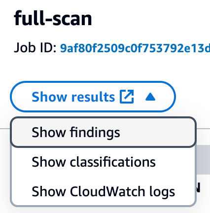
After the job completes, it’s time to review what Macie found in the data. Objects that Macie found with sensitive data will be presented as Findings in the Macie console. From the Jobs screen, choose the job you submitted. In the right-hand window, you will see the overview information for the job. From the overview window you can choose Show results menu and then select Show findings to view a list of the findings that were generated by the job.
Figure 1: Viewing Macie job findings
Each object where Macie found sensitive data will be listed as a single finding. If there were multiple types of sensitive data found in the object, each type of sensitive data and a count will be included in the details. Choose each of the findings that was produced and review the details to confirm what sensitive data was identified and if the sensitive data was discovered as you expected. Additionally, confirm that you don’t have findings for objects that you staged that were not supposed to have sensitive data so that you can confirm how Macie handles these types of objects. If you created custom data identifiers, review findings for the objects that included the custom data that you detect to confirm that the data was detected.
Enable automated discovery
Now that you understand how to use Macie to discover sensitive data, the next step in the POC is to enable automated discovery and use Macie to discover sensitive data across a larger collection of your existing S3 data.
You will be enabling automated discovery in Macie as a 30-day free trial. For the free trial, the scope of total data storage to be evaluated will be 150 GB. Use the following steps to guide your setup of the automated discovery feature:
After your delegated administrator account is configured, enable automated discovery. As part of enabling automated discovery, pay extra attention to the following items:
Set managed data identifiers. Ideally, choose the recommended data identifiers to help reduce noise. If there are specific managed data identifiers that you really want to see, then choose Custom to choose the ones you want.
Include custom data identifiers that you want to be used to evaluate your sensitive data.
Exclude buckets that you don’t want included in the scope for identifying sensitive data.
Include or exclude specific accounts that should be part of the POC. Step 5 of Enable automated discovery covers how to enable it for specific accounts.
You will see the first set of results 24 to 48 hours after you enable automated discovery. After that, you will see updates to the automated discovery results every 24 hours.
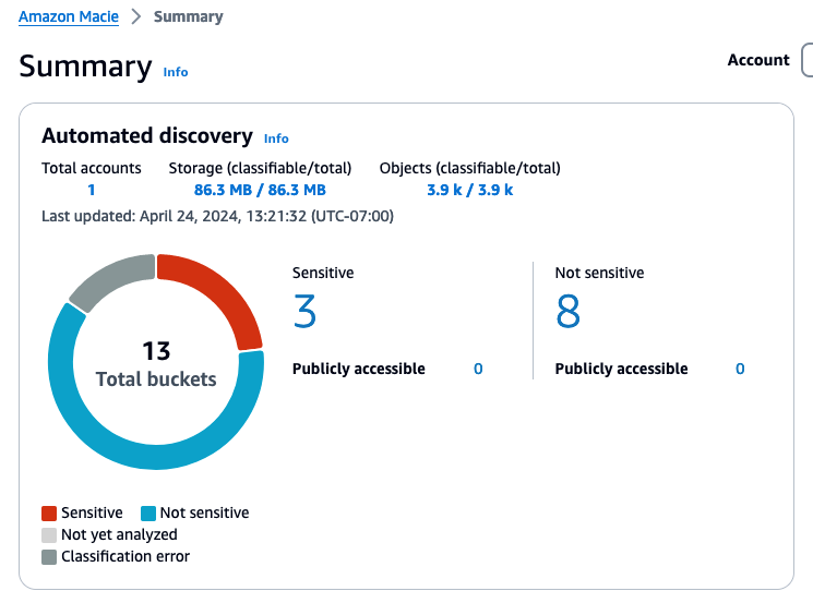
After automated discovery starts producing results, you will start seeing data in the Automated Discovery section of the Macie summary page in the console. The summary includes metrics for the total number of buckets eligible for discovery, counts for the number of buckets where sensitive data was or was not found, and how many of these buckets are public.
Figure 2: Example automated discovery summary metrics
Choosing a link for one of the counts will take you to the S3 buckets view with the appropriate filters applied.
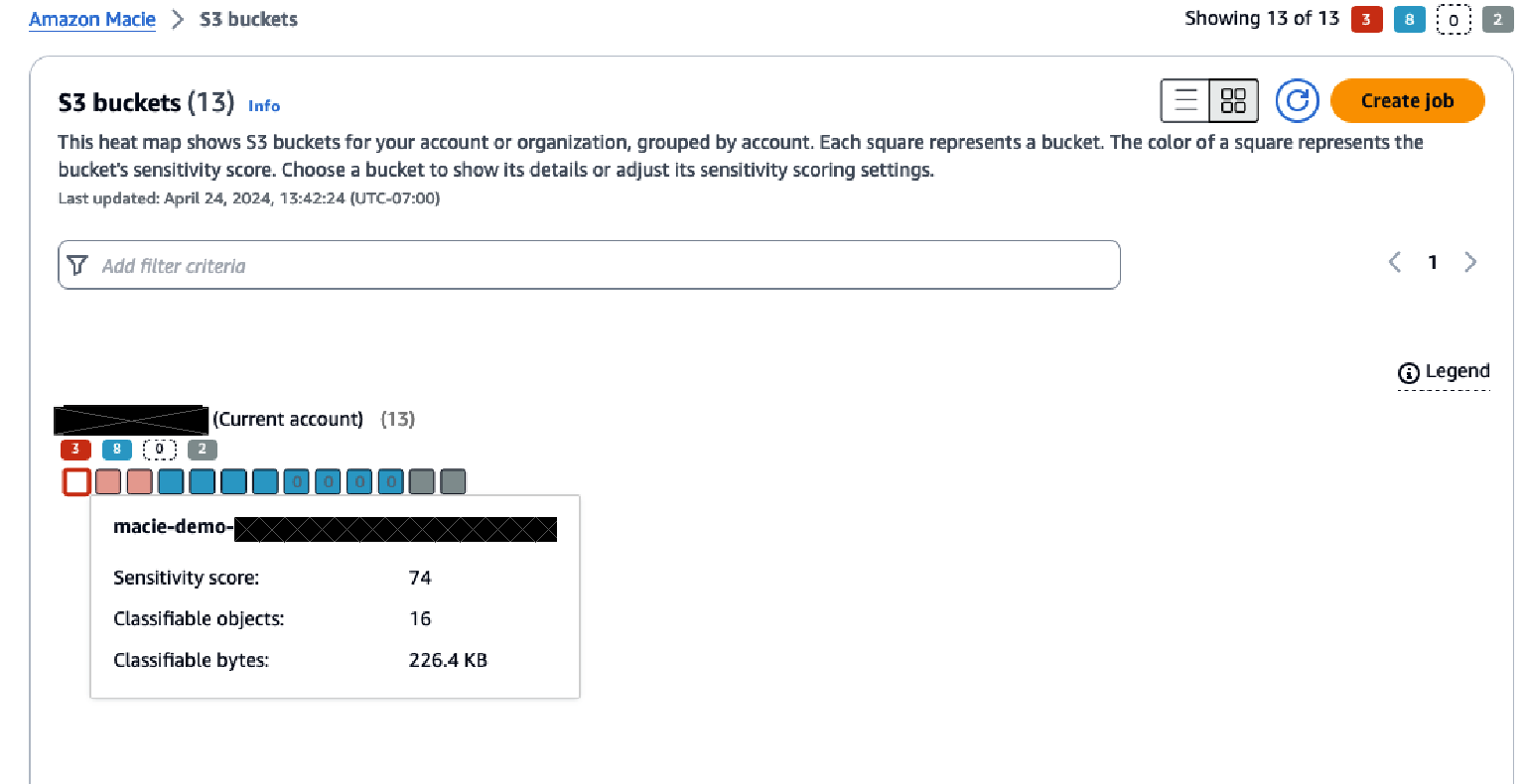
After reviewing the summary screen, choose S3 buckets from the navigation pane to see a heatmap that shows each account and the buckets within each account.
Figure 3: S3 bucket heatmap view in Macie
The heatmap provides point-in-time insights into the data that Macie has scanned, and in which buckets sensitive data has been identified or no sensitive data has been found.
Over time, this heatmap might change as automated data discovery continues sampling the data in each bucket. The heatmap view provides information on each organizational member account and insight about sensitive data within each bucket in the account.
The console displays the results as a set of colored squares for each account. Each square represents a bucket in that account and the color of the square indicates whether sensitive data was discovered in that bucket. Red indicates that some type of sensitive data has been found in the bucket, while blue indicates no sensitive data has been identified. If a bucket is blue, that means only that automated data discovery hasn’t identified sensitive data up to the point in time of the last scan, not that there is no sensitive data in the bucket.
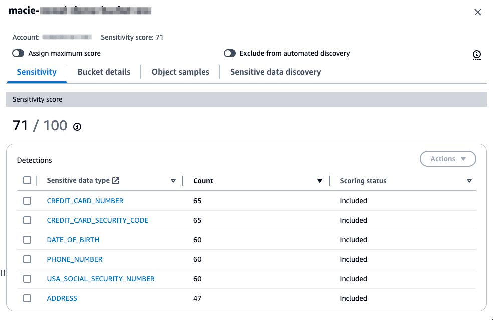
Hover over each bucket to see a summary of the sensitivity score of the bucket along with statistics about the data in the bucket. Choosing a bucket in the heatmap will open a window that provides more information about the bucket. This information includes the sensitivity score of the bucket, a summary of the types of sensitive data found in the bucket, which objects within the bucket have been sampled, statistics related to the data that has been scanned and data that is still to be scanned, and other information about the bucket.
Figure 4: S3 bucket sensitivity information in Macie
As part of your POC, it’s recommended that you investigate buckets that are reported to contain sensitive data. For your investigation, validate if the data identified is sensitive based on your organization’s data classification policy. Each Macie finding contains not only the details on the types of sensitive data identified, but also the location within the file where the sensitive data is located so that you can confirm the identified data is sensitive. The following is an example of a Macie finding in an Excel file where bank account numbers were found. This example shows the row and column where the sensitive data was found.
Investigating sensitive data with findings has detailed guidance around locating sensitive data from Macie findings, retrieving the sensitive data, and the schema for sensitive data locations. If the findings are true positives, make sure that the bucket has the right level of security configurations and permissions based on the data stored in the bucket.
In addition to reviewing the bucket level statistics that are generated by automated discovery, you can view the individual findings that were generated for each S3 object that was identified as having sensitive data. You can view the findings through the Findings tab in Macie or by choosing the sensitive data type when looking at the summary detections for a bucket.
Next steps
With the preceding POC, you should now have a more complete understanding of how Macie identifies sensitive data and how you can use the information that Macie provides about that data identified. As you complete your POC, there are a few next steps that other customers have taken after completing their POC with Macie.
Operationalize Macie output
In the POC steps, we outlined how to view the findings and the insights that the automated discovery provides. Before you proceed with Macie, you should have a plan for how you will operationalize the Macie output. This will help ensure that the remediation steps for identified sensitive data are directed to the correct parties.
Depending on what operational tools you have in place, the steps that you take to operationalize the output of Macie will vary. Many customers implement operational processes that cover the following areas:
The privacy or security team that’s responsible for Macie does an initial triage on the findings to confirm if there are true positives.
The privacy or security team defines their operational processes related to the summary dashboard and bucket sensitivity information that’s provided by automated discovery.
The team that owns the bucket where the sensitive data is located is provided the information needed to investigate the identified data and provide a response. Responses will vary but could include removal of the data, correcting the application that is writing the data, or applying additional security to the bucket.
A key part of operationalizing Macie output is also how you are getting and reviewing the signals related to Macie findings. As outlined in this post, you can view and investigate findings in the Macie console. At a steady state, customers find it beneficial to consume Macie findings using Amazon EventBridge, through Macie APIs, or through the integration of Macie with AWS Security Hub. These options can be used to incorporate the findings that are reported by Macie into the operational workflows and tools that work best for your organization and allow you to consume and address findings at scale. Monitoring and processing findings provides more insight into these integration approaches.
Store and retain sensitive data discovery results
As you move forward with Macie, it’s important to enable logging for each of the S3 objects that Macie has scanned. Macie creates an analysis record for each S3 object that’s in scope for a data discovery job or an automated discovery scan. These records are an audit of every object that Macie attempted to scan, including objects that didn’t contain sensitive data. Data discovery results are written to an S3 bucket that you own and where you control the data retention. These data discovery results can assist with analysis of records over time or to get a broader sense of what data Macie has scanned and which objects had sensitive data and which did not.
The data discovery scan results are stored as JSON Lines files. You can use multiple approaches to analyze and query these log files. The Amazon Macie Results Analytics GitHub repository provides instructions on how to configure Amazon Athena with tables that allow you to query the results of Macie discovery scan files.
Define the scope for Macie use
After a POC with Macie, you can set the scope of how you will use Macie in production by deciding which buckets don’t need to be evaluated and so can be excluded, such as buckets used for AWS logs and buckets deemed not in scope for sensitive data identification.
You can also refine the managed data identifiers that are required for detecting sensitive data. Based on what they learned from the POC. You can create custom data identifiers to help meet your data detection needs if necessary.
As you identify the sensitive data discovery jobs to run as part of your production use of Macie, keep in mind that these jobs are immutable. To edit an existing scheduled job, you must create a copy of the job with the updated configuration and cancel the original job for changes to take effect. Depending on the updated criteria for your job, you must do one of the following to help avoid re-scanning objects that were covered by the previous job:
Clear include existing objects when setting the scope. This will cause the new job to schedule only objects that were created between when it was first created and when it was run for the first time.
When setting the job scope, set the object attributes so that the object last modified date is the date of the last time the previous job ran. This helps ensure that when the new scheduled job runs, it evaluates only objects that weren’t covered by the previous job.
Clean up
To avoid incurring additional charges, disable Macie while you evaluate the value of the additional data protection provided. If S3 buckets were created for this POC, those should also be deleted.
Call to action
After the POC is complete, evaluate the results to determine how much using Macie can strengthen your organization’s data protection program. Based on that evaluation, you can identify how and where to use Macie for maximum effectiveness. Also consider how the information provided can be factored into operational workflows to get additional value from Macie.
Conclusion
This post outlined how you can use a POC to better understand how Amazon Macie can help meet your data discovery and classification needs. A well thought-out and implemented POC can provide valuable early insights and help you develop a more thorough understanding of what your data discovery and classification strategy should be. Planning your POC using the guidance in this post can help you determine more quickly if Macie is a fit for your company.
If you have feedback about this post, submit comments in the Comments section below. If you have questions about this post, contact AWS Support.
The PCI Security Standards Council (PCI SSC) is a global forum that connects stakeholders from the payments and payment processing industries to craft and facilitate adoption of data security standards and relevant resources that enable safe payments worldwide.
According to the PCI SSC website, “PCI Security Standards are developed specifically to protect payment account data throughout the payment lifecycle and to enable technology solutions that devalue this data and remove the incentive for criminals to steal it. They include standards for merchants, service providers, and financial institutions on security practices, technologies and processes, and standards for developers and vendors for creating secure payment products and solutions.”
Perhaps the most recognizable standard from PCI, their Data Security Standard (PCI DSS), is a global standard that provides a baseline of technical and operational requirements designed to protect account data. In March 2022, PCI SSC published version v4.0 of the standard, which replaces version v3.2.1. The updated version addresses emerging threats and technologies and enables innovative methods to combat new threats. This post will cover the changes to the standard that came with version 4.0 along with a high-level overview of how Rapid7 helps teams ensure their cloud-based applications can effectively implement and enforce compliance.
What’s New With Version 4.0, and Why Is It Important Now?
So, why are we talking about the new standard nearly two years after it was published? That’s because when the standard was published there was a two year transition period for organizations to adopt the new version and implement required changes that came with v4.0. During this transition period, organizations were given the option to assess against either PCI DSS v4.0 or PCI DSS v3.2.1.
For those that haven’t yet made the jump, the time is now This is because the transition period concluded on March 31, 2024, at which time version 3.2.1 was retired and organizations seeking PCI DSS certification will need to adhere to the new requirements and best practices. Important to note, there are some requirements that have been “future-dated.” For those requirements, organizations have been granted another full year, with those updates being required by March 31, 2025.
The changes were driven by direct feedback from organizations across the global payments industry. According to PCI, more than 200 organizations provided feedback to ensure the standard continues to meet the complex, ever-changing landscape of payment security.
Key changes for this version update include:
Flexibility in How Teams Achieve Compliance / Customized Approach
A primary goal for PCI DSS v4.0 was to provide greater flexibility for organizations in how they can achieve their security objectives. PCI DSS v4.0 introduces a new method – known as the Customized Approach – by which organizations can implement and validate PCI DSS controls Previously, organizations had the option of implementing Compensating controls, however these are only applicable when a situation arises whereby there is a constraint – such as legacy systems or processes – impacting the ability to meet a requirement.
PCI DSS v4.0 now provides organizations the means to choose to meet a requirement leveraging other means than the stated requirement. Requirement 12.3.2 and Appendices D and E outline the customized approach and how to apply it. To support customers, Rapid7’s new PCI DSS v4.0 compliance pack provides a greater number of insights than in previous iterations. This should lead to increased visibility and refinement in the process of choosing to mitigate and manage requirements.
A Targeted Approach to Risk Management
Alongside the customized approach concept, one of the most significant updates is the introduction of targeted risk analysis (TRA). TRAallows organizations to assess and respond to risks in the context of an organization’s specific operational environment. The PCI council has published guidance “PCI DSS v4 x: Targeted Risk Analysis Guidance” that outlines the two types of TRAs that an entity can employ regarding frequency of performing a given control and the second addressing any PCI DSS requirement for when an entity utilizes a customized approach.
To assist in understanding and having a consolidated view of security risks in their cloud environments, Rapid7 customers can leverage InsightCloudSec Layered Context and the recently introduced Risk Score feature. This feature combines a variety of risk signals, assigning a higher risk score to resources that suffer from toxic combinations or multiple risk vectors.Risk score holistically analyzes the risks that compound and increase the likelihood or impact of compromise.
Enhanced Validation Methods & Procedures
PCI DSS v4.0 has provided improvements to the self-assessment (SAQ) document and to the Report on Compliance (RoC) template, increasing alignment between them and the information summarized in an Attestation of Compliance to support organizations in their efforts when self-attesting or working with assessors to increase transparency and granularity.
New Requirements
PCI DSS v4.0 has brought with it a range of new requirements to address emerging threats. With modernization of network security controls, explicit guidance on cardholder data protections, and process maturity, the standard focuses on establishing sustainable controls and governance. While there are quite a few updates – which you can find detailed here on the summary of changes – let’s highlight a few of particular importance:
Multifactor authentication is now required for all access into the Cardholder Data Environment (CDE) – req. 8.5.1
Encryption of sensitive authentication data (SAD) – req. 3.3.3
New password requirements and updated specific password strength requirements: Passwords must now consist of 12 characters with special characters, uppercase and lowercase – reqs. 8.3.6 and 8.6.3
Access roles and privileges are based on least privilege access (LPA), and system components operate using deny by default – req. 7.2.5
Audit log reviews are performed using automated mechanisms – req. 10.4.1.1
These controls place role-based access control, configuration management, risk analysis and continuous monitoring as foundations, assisting organizations to mature and achieve their security objectives. Rapid7 can help with implementing and enforcing these new controls, with a host of solutions that offer PCI-related support – all of which have been updated to align with these new requirements.
How Rapid7 Supports Customers to Attain PCI DSS v4.0 Compliance
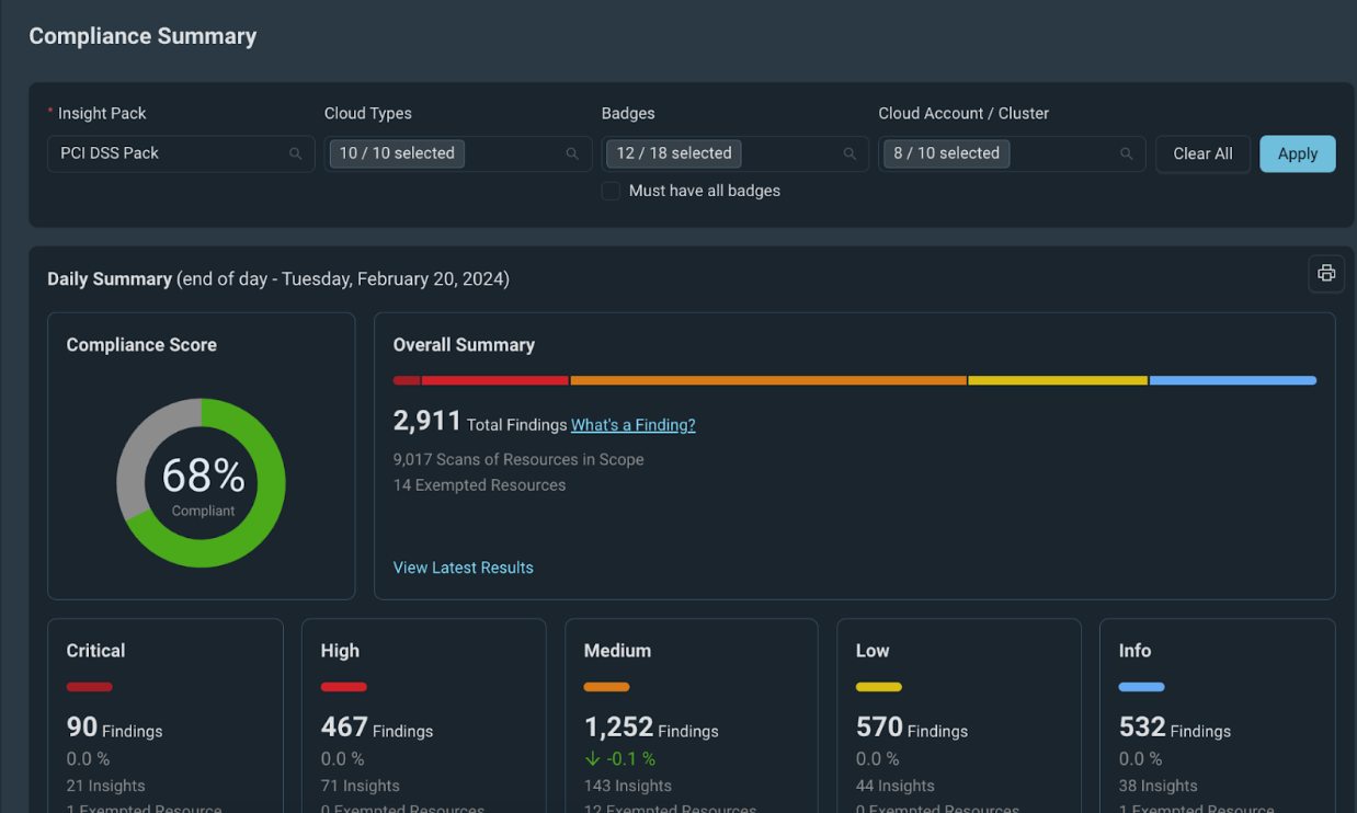
InsightCloudSec allows security teams to establish, continuously measure, and illustrate compliance against organizational policies. This is accomplished via compliance packs, which are sets of checks that can be used to continuously assess your entire cloud environment – whether single or multi-cloud. The platform comes out of the box with dozens of compliance packs, including a dedicated pack for the PCI DSS v4.0.
InsightCloudSec assesses your cloud environments in real-time for compliance with the requirements and best practices outlined by PCI It also enables teams to identify, assess, and act on noncompliant resources when misconfigurations are detected. If you so choose, you can make use of the platform’s native, no-code automation to remediate the issue the moment it’s detected, whether that means alerting relevant resource owners, adjusting the configuration or permissions directly or even deleting the non-compliant resource altogether without any human intervention. Check out the demo to learn more about how InsightCloudSec helps continuously and automatically enforce cloud security standards.
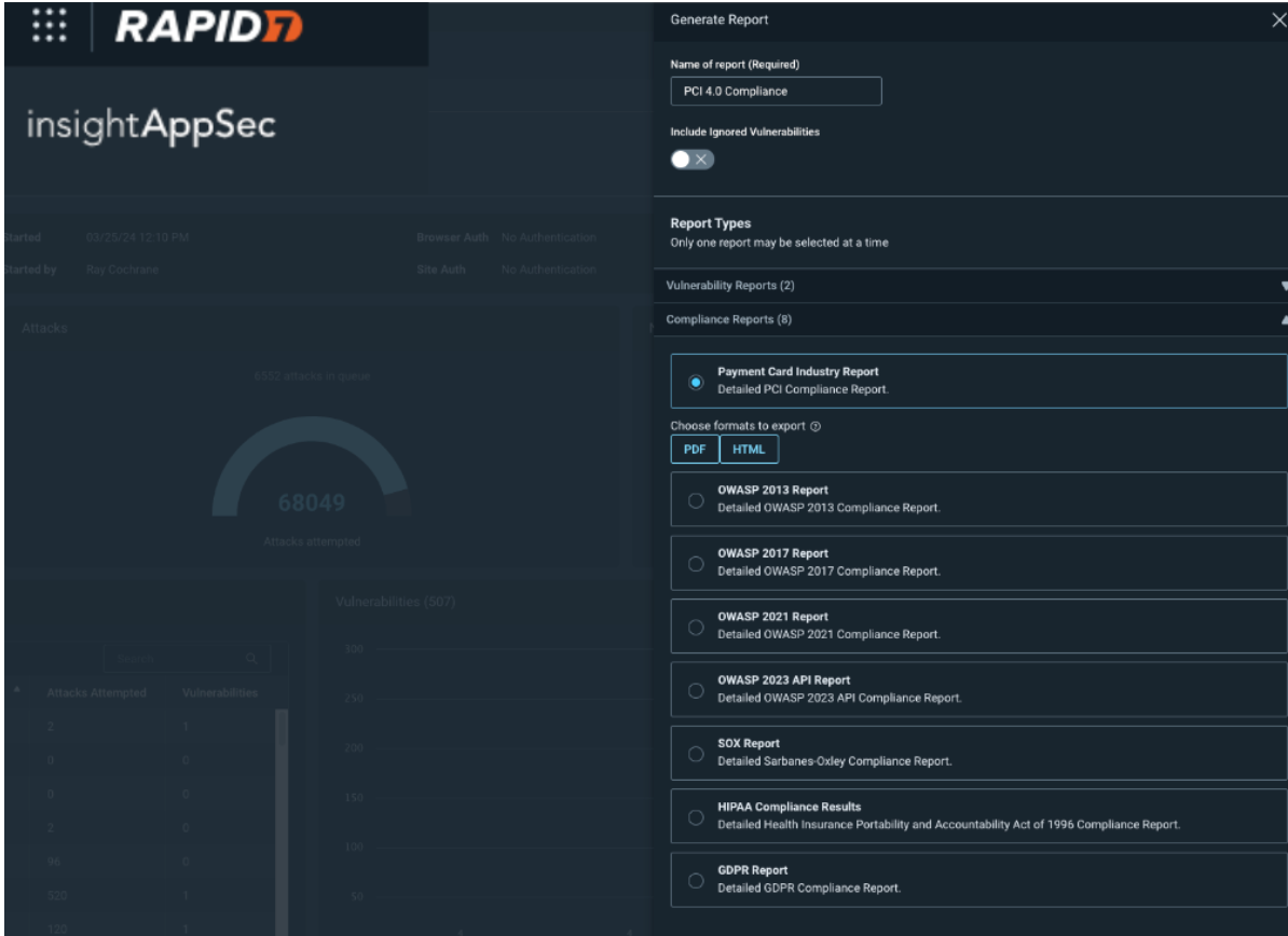
InsightAppSec also enables measurement against PCI v4.0 requirements to help you obtain PCI compliance. It allows users to create a PCI v4.0 report to help prepare for an audit, assessment or a questionnaire around PCI compliance. The PCI report gives you the ability to uncover potential issues that will affect the outcome or any of these exercises. Crucially, the report allows you to take action and secure critical vulnerabilities on any assets that deal with payment card data. PCI compliance auditing comes out of the box and is simple to generate once you have completed a scan against which to run the report.
InsightAppSec achieves this coverage by cross referencing and then mapping our suite of 100+ attack modules against PCI requirements, identifying which attacks are relevant to particular requirements and then attempting to exploit your application with those attacks to obtain areas where your application may be vulnerable. Those vulnerabilities are then packaged up in the PCI 4.0 report where you can see vulnerabilities listed by PCI requirements This provides you with crucial insights into any vulnerabilities you may have as well as enabling management of those vulnerabilities in a simplistic format.
For InsightVM customers, an important change in the revision is the need to perform authenticated internal vulnerability scans for requirement 11.3.1.2. Previous versions of the standard allowed for internal scanning without the use of credentials, which is no longer sufficient. For more details see this blog post.
Rapid7 provides a wide array of solutions to assist you in your compliance and governance efforts. Contact a member of our team to learn more about any of these capabilities or sign up for a free trial.
Amazon Web Services (AWS) is pleased to announce that AWS Payment Cryptography is certified for Payment Card Industry Personal Identification Number (PCI PIN) version 3.1 and as a PCI Point-to-Point Encryption (P2PE) version 3.1 Decryption Component.
With Payment Cryptography, your payment processing applications can use payment hardware security modules (HSMs) that are PCI PIN Transaction Security (PTS) HSM certified and fully managed by AWS, with PCI PIN and P2PE-compliant key management. These attestations give you the flexibility to deploy your regulated workloads with reduced compliance overhead.
The PCI P2PE Decryption Component enables PCI P2PE Solutions to use AWS to decrypt credit card transactions from payment terminals, and PCI PIN attestation is required for applications that process PIN-based debit transactions. According to PCI, “Use of a PCI P2PE Solution can also allow merchants to reduce where and how the PCI DSS applies within their retail environment, increasing security of customer data while simplifying compliance with the PCI DSS”.
Coalfire, a third-party Qualified PIN Assessor (QPA) and Qualified Security Assessor (P2PE), evaluated Payment Cryptography. Customers can access the PCI PIN Attestation of Compliance (AOC) report, the PCI PIN Shared Responsibility Summary, and the PCI P2PE Attestation of Validation through AWS Artifact.
To learn more about our PCI program and other compliance and security programs, see the AWS Compliance Programs page. As always, we value your feedback and questions; reach out to the AWS Compliance team through the Contact Us page.
If you have feedback about this post, submit comments in the Comments section below. If you have questions about this post, contact AWS Support.
Many customers building applications on Amazon Web Services (AWS) use Stripe global payment services to help get their product out faster and grow revenue, especially in the internet economy. It’s critical for customers to securely and properly handle the credentials used to authenticate with Stripe services. Much like your AWS API keys, which enable access to your AWS resources, Stripe API keys grant access to the Stripe account, which allows for the movement of real money. Therefore, you must keep Stripe’s API keys secret and well-controlled. And, much like AWS keys, it’s important to invalidate and re-issue Stripe API keys that have been inadvertently committed to GitHub, emitted in logs, or uploaded to Amazon Simple Storage Service (Amazon S3).
Customers have asked us for ways to reduce the risk of unintentionally exposing Stripe API keys, especially when code files and repositories are stored in Amazon S3. To help meet this need, we collaborated with Stripe to develop a new managed data identifier that you can use to help discover and protect Stripe API keys.
“I’m really glad we could collaborate with AWS to introduce a new managed data identifier in Amazon Macie. Mutual customers of AWS and Stripe can now scan S3 buckets to detect exposed Stripe API keys.” — Martin Pool,Staff Engineer in Cloud Security at Stripe
In this post, we will show you how to use the new managed data identifier in Amazon Macie to discover and protect copies of your Stripe API keys.
About Stripe API keys
Stripe provides payment processing software and services for businesses. Using Stripe’s technology, businesses can accept online payments from customers around the globe.
Stripe authenticates API requests by using API keys, which are included in the request. Stripe takes various measures to help customers keep their secret keys safe and secure. Stripe users can generate test-mode keys, which can only access simulated test data, and which doesn’t move real money. Stripe encourages its customers to use only test API keys for testing and development purposes to reduce the risk of inadvertent disclosure of live keys or of accidentally generating real charges.
Stripe also supports publishable keys, which you can make publicly accessible in your web or mobile app’s client-side code to collect payment information.
In this blog post, we focus on live-mode keys, which are the primary security concern because they can access your real data and cause money movement. These keys should be closely held within the production services that need to use them. Stripe allows keys to be restricted to read or write specific API resources, or used only from certain IP ranges, but even with these restrictions, you should still handle live mode keys with caution.
Stripe keys have distinctive prefixes to help you detect them such as sk_live_ for secret keys, and rk_live_ for restricted keys (which are also secret).
Amazon Macie
Amazon Macie is a fully managed service that uses machine learning (ML) and pattern matching to discover and help protect your sensitive data, such as personally identifiable information. Macie can also provide detailed visibility into your data and help you align with compliance requirements by identifying data that needs to be protected under various regulations, such as the General Data Protection Regulation (GDPR) and the Health Insurance Portability and Accountability Act (HIPAA).
Macie supports a suite of managed data identifiers to make it simpler for you to configure and adopt. Managed data identifiers are prebuilt, customizable patterns that help automatically identify sensitive data, such as credit card numbers, social security numbers, and email addresses.
Now, Macie has a new managed data identifier STRIPE_CREDENTIALS that you can use to identify Stripe API secret keys.
Configure Amazon Macie to detect Stripe credentials
In this section, we show you how to use the managed data identifier STRIPE_CREDENTIALS to detect Stripe API secret keys. We recommend that you carry out these tutorial steps in an AWS account dedicated to experimentation and exploration before you move forward with detection in a production environment.
Prerequisites
To follow along with this walkthrough, complete the following prerequisites.
The first step is to create some example objects in an S3 bucket in the AWS account. The objects contain strings that resemble Stripe secret keys. You will use the example data later to demonstrate how Macie can detect Stripe secret keys.
Note: The keys mentioned in the preceding files are mock data and aren’t related to actual live Stripe keys.
Create a Macie job with the STRIPE_CREDENTIALS managed data identifier
Using Macie, you can scan your S3 buckets for sensitive data and security risks. In this step, you run a one-time Macie job to scan an S3 bucket and review the findings.
To create a Macie job with STRIPE_CREDENTIALS
Open theAmazon Macie console, and in the left navigation pane, choose Jobs. On the top right, choose Create job.
Figure 1: Create Macie Job
Select the bucket that you want Macie to scan or specify bucket criteria, and then choose Next.
Figure 2: Select S3 bucket
Review the details of the S3 bucket, such as estimated cost, and then choose Next.
Figure 3: Review S3 bucket
On the Refine the scope page, choose One-time job, and then choose Next.
Note: After you successfully test, you can schedule the job to scan S3 buckets at the frequency that you choose.
Figure 4: Select one-time job
For Managed data identifier options, select Custom and then select Use specific managed data identifiers. For Select managed data identifiers, search for STRIPE_CREDENTIALS and then select it. Choose Next.
Figure 5: Select managed data identifier
Enter a name and an optional description for the job, and then choose Next.
Figure 6: Enter job name
Review the job details and choose Submit. Macie will create and start the job immediately, and the job will run one time.
When the Status of the job shows Complete, select the job, and from the Show results dropdown, select Show findings.
Figure 7: Select the job and then select Show findings
You can now review the findings for sensitive data in your S3 bucket. As shown in Figure 8, Macie detected Stripe keys in each of the four files, and categorized the findings as High severity. You can review and manage the findings in the Macie console, retrieve them through the Macie API for further analysis, send them to Amazon EventBridge for automated processing, or publish them to AWS Security Hub for a comprehensive view of your security state.
Figure 8: Review the findings
Respond to unintended disclosure of Stripe API keys
If you discover Stripe live-mode keys (or other sensitive data) in an S3 bucket, then through the Stripe dashboard, you can roll your API keys to revoke access to the compromised key and generate a new one. This helps ensure that the key can’t be used to make malicious API requests. Make sure that you install the replacement key into the production services that need it. In the longer term, you can take steps to understand the path by which the key was disclosed and help prevent a recurrence.
Conclusion
In this post, you learned about the importance of safeguarding Stripe API keys on AWS. By using Amazon Macie with managed data identifiers, setting up regular reviews and restricted access to S3 buckets, training developers in security best practices, and monitoring logs and repositories, you can help mitigate the risk of key exposure and potential security breaches. By adhering to these practices, you can help ensure a robust security posture for your sensitive data on AWS.
If you have feedback about this post, submit comments in the Comments section below. If you have questions about this post, start a new thread on Amazon Macie re:Post.
Amazon Web Services is pleased to announce that eight additional AWS services have been added to the scope of our Payment Card Industry Data Security Standard (PCI DSS) v4.0 certification:
Customers can access the PCI DSS package in AWS Artifact. The package includes the following:
Attestation of Compliance (AoC) — shows that AWS has been successfully validated against the PCI DSS standard.
AWS Responsibility Summary – provides information to help you effectively manage a PCI cardholder environment on AWS and better understand your responsibility regarding operating controls to effectively develop and operate a secure environment on AWS.
To learn more about our PCI program and other compliance and security programs, see the AWS Compliance Programs page. As always, we value your feedback and questions; reach out to the AWS Compliance team through the Contact Us page.
Want more AWS Security news? Follow us on Twitter.
Compliance with the Payment Card Industry Data Security Standard (PCI DSS) is critical for organizations that handle cardholder data. Achieving and maintaining PCI DSS compliance can be a complex and challenging endeavor. Serverless technology has transformed application development, offering agility, performance, cost, and security.
In this blog post, we examine the benefits of using AWS serverless services and highlight how you can use them to help align with your PCI DSS compliance responsibilities. You can remove additional undifferentiated compliance heavy lifting by building modern applications with abstracted AWS services. We review an example payment application and workflow that uses AWS serverless services and showcases the potential reduction in effort and responsibility that a serverless architecture could provide to help align with your compliance requirements. We present the review through the lens of a merchant that has an ecommerce website and include key topics such as access control, data encryption, monitoring, and auditing—all within the context of the example payment application. We don’t discuss additional service provider requirements from the PCI DSS in this post.
This example will help you navigate the intricate landscape of PCI DSS compliance. This can help you focus on building robust and secure payment solutions without getting lost in the complexities of compliance. This can also help reduce your compliance burden and empower you to develop your own secure, scalable applications. Join us in this journey as we explore how AWS serverless services can help you meet your PCI DSS compliance objectives.
Disclaimer
This document is provided for the purposes of information only; it is not legal advice, and should not be relied on as legal advice. Customers are responsible for making their own independent assessment of the information in this document. This document: (a) is for informational purposes only, (b) represents current AWS product offerings and practices, which are subject to change without notice, and (c) does not create any commitments or assurances from AWS and its affiliates, suppliers or licensors. AWS products or services are provided “as is” without warranties, representations, or conditions of any kind, whether express or implied. The responsibilities and liabilities of AWS to its customers are controlled by AWS agreements, and this document is not part of, nor does it modify, any agreement between AWS and its customers.
AWS encourages its customers to obtain appropriate advice on their implementation of privacy and data protection environments, and more generally, applicable laws and other obligations relevant to their business.
PCI DSS v4.0 and serverless
In April 2022, the Payment Card Industry Security Standards Council (PCI SSC) updated the security payment standard to “address emerging threats and technologies and enable innovative methods to combat new threats.” Two of the high-level goals of these updates are enhancing validation methods and procedures and promoting security as a continuous process. Adopting serverless architectures can help meet some of the new and updated requirements in version 4.0, such as enhanced software and encryption inventories. If a customer has access to change a configuration, it’s the customer’s responsibility to verify that the configuration meets PCI DSS requirements. There are more than 20 PCI DSS requirements applicable to Amazon Elastic Compute Cloud (Amazon EC2). To fulfill these requirements, customer organizations must implement controls such as file integrity monitoring, operating system level access management, system logging, and asset inventories. Using AWS abstracted services in this scenario can remove undifferentiated heavy lifting from your environment. With abstracted AWS services, because there is no operating system to manage, AWS becomes responsible for maintaining consistent time settings for an abstracted service to meet Requirement 10.6. This will also shift your compliance focus more towards your application code and data.
This makes more of your PCI DSS responsibility addressable through the AWS PCI DSS Attestation of Compliance (AOC) and Responsibility Summary. This attestation package is available to AWS customers through AWS Artifact.
Reduction in compliance burden
You can use three common architectural patterns within AWS to design payment applications and meet PCI DSS requirements: infrastructure, containerized, and abstracted. We look into EC2 instance-based architecture (infrastructure or containerized patterns) and modernized architectures using serverless services (abstracted patterns). While both approaches can help align with PCI DSS requirements, there are notable differences in how they handle certain elements. EC2 instances provide more control and flexibility over the underlying infrastructure and operating system, assisting you in customizing security measures based on your organization’s operational and security requirements. However, this also means that you bear more responsibility for configuring and maintaining security controls applicable to the operating systems, such as network security controls, patching, file integrity monitoring, and vulnerability scanning.
On the other hand, serverless architectures similar to the preceding example can reduce much of the infrastructure management requirements. This can relieve you, the application owner or cloud service consumer, of the burden of configuring and securing those underlying virtual servers. This can streamline meeting certain PCI requirements, such as file integrity monitoring, patch management, and vulnerability management, because AWS handles these responsibilities.
Using serverless architecture on AWS can significantly reduce the PCI compliance burden. Approximately 43 percent of the overall PCI compliance requirements, encompassing both technical and non-technical tests, are addressed by the AWS PCI DSS Attestation of Compliance.
Customer responsible 52%
AWS responsible 43%
N/A 5%
The following table provides an analysis of each PCI DSS requirement against the serverless architecture in Figure 1, which shows a sample payment application workflow. You must evaluate your own use and secure configuration of AWS workload and architectures for a successful audit.
PCI DSS 4.0 requirements
Test cases
Customer responsible
AWS responsible
N/A
Requirement 1: Install and maintain network security controls
35
13
22
0
Requirement 2: Apply secure configurations to all system components
27
16
11
0
Requirement 3: Protect stored account data
55
24
29
2
Requirement 4: Protect cardholder data with strong cryptography during transmission over open, public networks
12
7
5
0
Requirement 5: Protect all systems and networks from malicious software
25
4
21
0
Requirement 6: Develop and maintain secure systems and software
35
31
4
0
Requirement 7: Restrict access to system components and cardholder data by business need-to-know
22
19
3
0
Requirement 8: Identify users and authenticate access to system components
52
43
6
3
Requirement 9: Restrict physical access to cardholder data
56
3
53
0
Requirement 10: Log and monitor all access to system components and cardholder data
38
17
19
2
Requirement 11: Test security of systems and networks regularly
51
22
23
6
Requirement 12: Support information security with organizational policies
56
44
2
10
Total
464
243
198
23
Percentage
52%
43%
5%
Note: The preceding table is based on the example reference architecture that follows. The actual extent of PCI DSS requirements reduction can vary significantly depending on your cardholder data environment (CDE) scope, implementation, and configurations.
Sample payment application and workflow
This example serverless payment application and workflow in Figure 1 consists of several interconnected steps, each using different AWS services. The steps are listed in the following text and include brief descriptions. They cover two use cases within this example application — consumers making a payment and a business analyst generating a report.
The example outlines a basic serverless payment application workflow using AWS serverless services. However, it’s important to note that the actual implementation and behavior of the workflow may vary based on specific configurations, dependencies, and external factors. The example serves as a general guide and may require adjustments to suit the unique requirements of your application or infrastructure.
Several factors, including but not limited to, AWS service configurations, network settings, security policies, and third-party integrations, can influence the behavior of the system. Before deploying a similar solution in a production environment, we recommend thoroughly reviewing and adapting the example to align with your specific use case and requirements.
Keep in mind that AWS services and features may evolve over time, and new updates or changes may impact the behavior of the components described in this example. Regularly consult the AWS documentation and ensure that your configurations adhere to best practices and compliance standards.
This example is intended to provide a starting point and should be considered as a reference rather than an exhaustive solution. Always conduct thorough testing and validation in your specific environment to ensure the desired functionality and security.
Figure 1: Serverless payment architecture and workflow
Use case 1: Consumers make a payment
Consumers visit the e-commerce payment page to make a payment.
The request is routed to the payment application’s domain using Amazon Route 53, which acts as a DNS service.
The payment page is protected by AWS WAF to inspect the initial incoming request for any malicious patterns, web-based attacks (such as cross-site scripting (XSS) attacks), and unwanted bots.
An HTTPS GET request (over TLS) is sent to the public target IP. Amazon CloudFront, a content delivery network (CDN), acts as a front-end proxy and caches and fetches static content from an Amazon Simple Storage Service (Amazon S3) bucket.
AWS WAF inspects the incoming request for any malicious patterns, if the request is blocked, the request doesn’t return static content from the S3 bucket.
User authentication and authorization are handled by Amazon Cognito, providing a secure login and scalable customer identity and access management system (CIAM)
AWS WAF processes the request to protect against web exploits, then Amazon API Gateway forwards it to the payment application API endpoint.
API Gateway launches AWS Lambda functions to handle payment requests. AWS Step Functions state machine oversees the entire process, directing the running of multiple Lambda functions to communicate with the payment processor, initiate the payment transaction, and process the response.
The cardholder data (CHD) is temporarily cached in Amazon DynamoDB for troubleshooting and retry attempts in the event of transaction failures.
A Lambda function validates the transaction details and performs necessary checks against the data stored in DynamoDB. A web notification is sent to the consumer for any invalid data.
A Lambda function calculates the transaction fees.
A Lambda function authenticates the transaction and initiates the payment transaction with the third-party payment provider.
A Lambda function is initiated when a payment transaction with the third-party payment provider is completed. It receives the transaction status from the provider and performs multiple actions.
Use case 2: An admin or analyst generates the report for non-PCI data
An admin accesses the web-based reporting dashboard using their browser to generate a report.
The request is routed to AWS WAF to verify the source that initiated the request.
An HTTPS GET request (over TLS) is sent to the public target IP. CloudFront fetches static content from an S3 bucket.
AWS WAF inspects incoming requests for any malicious patterns, if the request is blocked, the request doesn’t return static content from the S3 bucket. The validated traffic is sent to Amazon S3 to retrieve the reporting page.
The backend requests of the reporting page pass through AWS WAF again to provide protection against common web exploits before being forwarded to the reporting API endpoint through API Gateway.
API Gateway launches a Lambda function for report generation. The Lambda function retrieves data from DynamoDB storage for the reporting mechanism.
The AWS Security Token Service (AWS STS) issues temporary credentials to the Lambda service in the non-PCI serverless account, allowing it to launch the Lambda function in the PCI serverless account. The Lambda function retrieves non-PCI data and writes it into DynamoDB.
The Lambda function fetches the non-PCI data based on the report criteria from the DynamoDB table from the same account.
Additional AWS security and governance services that would be implemented throughout the architecture are shown in Figure 1, Label-25. For example, Amazon CloudWatch monitors and alerts on all the Lambda functions within the environment.
Label-26 demonstrates frameworks that can be used to build the serverless applications.
Scoping and requirements
Now that we’ve established the reference architecture and workflow, lets delve into how it aligns with PCI DSS scope and requirements.
PCI scoping
Serverless services are inherently segmented by AWS, but they can be used within the context of an AWS account hierarchy to provide various levels of isolation as described in the reference architecture example.
Segregating PCI data and non-PCI data into separate AWS accounts can help in de-scoping non-PCI environments and reducing the complexity and audit requirements for components that don’t handle cardholder data.
PCI serverless production account
This AWS account is dedicated to handling PCI data and applications that directly process, transmit, or store cardholder data.
Services such as Amazon Cognito, DynamoDB, API Gateway, CloudFront, Amazon SNS, Amazon SES, Amazon SQS, and Step Functions are provisioned in this account to support the PCI data workflow.
Security controls, logging, monitoring, and access controls in this account are specifically designed to meet PCI DSS requirements.
Non-PCI serverless production account
This separate AWS account is used to host applications that don’t handle PCI data.
Since this account doesn’t handle cardholder data, the scope of PCI DSS compliance is reduced, simplifying the compliance process.
Note: You can use AWS Organizations to centrally manage multiple AWS accounts.
Now, let’s look at the PCI DSS requirements that this architectural pattern can help address.
Requirement 1: Install and maintain network security controls
Network security controls are limited to AWS Identity and Access Management (IAM) and application permissions because there is no customer controlled or defined network. VPC-centric requirements aren’t applicable because there is no VPC. The configuration settings for serverless services can be covered under Requirement 6 to for secure configuration standards. This supports compliance with Requirements 1.2 and 1.3.
Requirement 2: Apply secure configurations to all system components
AWS services are single function by default and exist with only the necessary functionality enabled for the functioning of that service. This supports compliance with much of Requirement 2.2.
Access to AWS services is considered non-console and only accessible through HTTPS through the service API. This supports compliance with Requirement 2.2.7.
The wireless requirements under Requirement 2.3 are not applicable, because wireless environments don’t exist in AWS environments.
Requirement 3: Protect stored account data
AWS is responsible for destruction of account data configured for deletion based on DynamoDB Time to Live (TTL) values. This supports compliance with Requirement 3.2.
DynamoDB and Amazon S3 offer secure storage of account data, encryption by default in transit and at rest, and integration with AWS Key Management Service (AWS KMS). This supports compliance with Requirements 3.5 and 4.2.
AWS is responsible for the generation, distribution, storage, rotation, destruction, and overall protection of encryption keys within AWS KMS. This supports compliance with Requirements 3.6 and 3.7.
Manual cleartext cryptographic keys aren’t available in this solution, Requirement 3.7.6 is not applicable.
Requirement 4: Protect cardholder data with strong cryptography during transmission over open, public networks
AWS Certificate Manager (ACM) integrates with API Gateway and enables the use of trusted certificates and HTTPS (TLS) for secure communication between clients and the API. This supports compliance with Requirement 4.2.
Requirement 4.2.1.2 is not applicable because there are no wireless technologies in use in this solution. Customers are responsible for ensuring strong cryptography exists for authentication and transmission over other wireless networks they manage outside of AWS.
Requirement 4.2.2 is not applicable because no end-user technologies exist in this solution. Customers are responsible for ensuring the use of strong cryptography if primary account numbers (PAN) are sent through end-user messaging technologies in other environments.
Requirement 5: Protect a ll systems and networks from malicious software
There are no customer-managed compute resources in this example payment environment, Requirements 5.2 and 5.3 are the responsibility of AWS.
Requirement 6: Develop and maintain secure systems and software
Amazon Inspector helps identify vulnerabilities and security weaknesses in the payment application’s code, dependencies, and configuration. This supports compliance with Requirement 6.3.
AWS WAF is designed to protect applications from common attacks, such as SQL injections, cross-site scripting, and other web exploits. AWS WAF can filter and block malicious traffic before it reaches the application. This supports compliance with Requirement 6.4.2.
Requirement 7: Restrict access to system components and cardholder data by business need to know
IAM and Amazon Cognito allow for fine-grained role- and job-based permissions and access control. Customers can use these capabilities to configure access following the principles of least privilege and need-to-know. IAM and Cognito support the use of strong identification, authentication, authorization, and multi-factor authentication (MFA). This supports compliance with much of Requirement 7.
Requirement 8: Identify users and authenticate access to system components
IAM and Amazon Cognito also support compliance with much of Requirement 8.
Some of the controls in this requirement are usually met by the identity provider for internal access to the cardholder data environment (CDE).
Requirement 9: Restrict physical access to cardholder data
AWS is responsible for the destruction of data in DynamoDB based on the customer configuration of content TTL values for Requirement 9.4.7. Customers are responsible for ensuring their database instance is configured for appropriate removal of data by enabling TTL on DDB attributes.
Requirement 9 is otherwise not applicable for this serverless example environment because there are no physical media, electronic media not already addressed under Requirement 3.2, or hard-copy materials with cardholder data. AWS is responsible for the physical infrastructure under the Shared Responsibility Model.
Requirement 10: Log and monitor all access to system components and cardholder data
AWS CloudTrail provides detailed logs of API activity for auditing and monitoring purposes. This supports compliance with Requirement 10.2 and contains all of the events and data elements listed.
CloudWatch can be used for monitoring and alerting on system events and performance metrics. This supports compliance with Requirement 10.4.
AWS Security Hub provides a comprehensive view of security alerts and compliance status, consolidating findings from various security services, which helps in ongoing security monitoring and testing. Customers must enable PCI DSS security standard, which supports compliance with Requirement 10.4.2.
AWS is responsible for maintaining accurate system time for AWS services. In this example, there are no compute resources for which customers can configure time. Requirement 10.6 is addressable through the AWS Attestation of Compliance and Responsibility Summary available in AWS Artifact.
Requirement 11: Regularly test security systems and processes
Testing for rogue wireless activity within the AWS-based CDE is the responsibility of AWS. AWS is responsible for the management of the physical infrastructure under Requirement 11.2. Customers are still responsible for wireless testing for their environments outside of AWS, such as where administrative workstations exist.
AWS is responsible for internal vulnerability testing of AWS services, and supports compliance with Requirement 11.3.1.
Amazon GuardDuty, a threat detection service that continuously monitors for malicious activity and unauthorized access, providing continuous security monitoring. This supports the IDS requirements under Requirement 11.5.1, and covers the entire AWS-based CDE.
AWS Config allows customers to catalog, monitor and manage configuration changes for their AWS resources. This supports compliance with Requirement 11.5.2.
Customers can use AWS Config to monitor the configuration of the S3 bucket hosting the static website. This supports compliance with Requirement 11.6.1.
Requirement 12: Support information security with organizational policies and programs
Customers can download the AWS AOC and Responsibility Summary package from Artifact to support Requirement 12.8.5 and the identification of which PCI DSS requirements are managed by the third-party service provider (TSPS) and which by the customer.
Conclusion
Using AWS serverless services when developing your payment application can significantly help reduce the number of PCI DSS requirements you need to meet by yourself. By offloading infrastructure management to AWS and using serverless services such as Lambda, API Gateway, DynamoDB, Amazon S3, and others, you can benefit from built-in security features and help align with your PCI DSS compliance requirements.
Contact us to help design an architecture that works for your organization. AWS Security Assurance Services is a Payment Card Industry-Qualified Security Assessor company (PCI-QSAC) and HITRUST External Assessor firm. We are a team of industry-certified assessors who help you to achieve, maintain, and automate compliance in the cloud by tying together applicable audit standards to AWS service-specific features and functionality. We help you build on frameworks such as PCI DSS, HITRUST CSF, NIST, SOC 2, HIPAA, ISO 27001, GDPR, and CCPA.
More information on how to build applications using AWS serverless technologies can be found at Serverless on AWS.
Want more AWS Security news? Follow us on Twitter.
Amazon Web Services (AWS) is pleased to announce that seven additional AWS services have been added to the scope of our Payment Card Industry Data Security Standard (PCI DSS) and Payment Card Industry Three-Domain Secure (PCI 3DS) certifications.
The compliance package for PCI DSS and 3DS includes the Attestation of Compliance (AOC), which shows that AWS has been successfully validated against these standards; and the AWS Responsibility Summary, which customers can use to better understand their responsibility regarding operating controls to effectively develop and operate a secure environment on AWS.
These are the seven additional services that have been added to the scope:
Coalfire, a third-party Qualified Security Assessor (QSA), evaluated AWS. Customers can access the AOC and the Responsibility Summary through AWS Artifact, a self-service portal for on-demand access to AWS compliance reports.
To learn more about our PCI program and other compliance and security programs, see the AWS Compliance Programs page. As always, we value your feedback and questions; reach out to the AWS Compliance team through the Contact Us page.
If you have feedback about this post, submit comments in the Comments section below. If you have questions about this post, contact AWS Support.
Want more AWS Security news? Follow us on Twitter.
Amazon Web Services (AWS) has re-published the whitepaper Architecting for PCI DSS Scoping and Segmentation on AWS to provide guidance on how to properly define the scope of your Payment Card Industry (PCI) Data Security Standard (DSS) workloads that are running in the AWS Cloud. The whitepaper has been refreshed to include updated AWS best practices and technologies, and updates that are applicable to the new PCI DSS v4.0 requirements. The whitepaper looks at how to define segmentation boundaries between your in-scope and out-of-scope resources by using cloud-based AWS services.
The whitepaper is intended for engineers and solution builders, but it also serves as a guide for Qualified Security Assessors (QSAs) and internal security assessors (ISAs) to better understand the different segmentation controls that are available within AWS products and services, along with associated scoping considerations.
Compared to on-premises environments, software-defined networking on AWS transforms the scoping process for applications by providing additional segmentation controls beyond network segmentation. Thoughtful design of your applications and selection of security-impacting services for implementing your required controls can reduce the number of systems and services in your cardholder data environment (CDE).
Amazon Macie is a fully managed data security service that uses machine learning and pattern matching to discover and help protect your sensitive data, such as personally identifiable information (PII), payment card data, and Amazon Web Services (AWS) credentials. Analyzing large volumes of data for the presence of sensitive information can be expensive, due to the nature of compute-intensive operations involved in the process.
Macie offers several capabilities to help customers reduce the cost of discovering sensitive data, including automated data discovery, which can reduce your spend with new data sampling techniques that are custom-built for Amazon Simple Storage Service (Amazon S3). In this post, we will walk through such Macie capabilities and best practices so that you can cost-efficiently discover sensitive data with Macie.
Overview of the Macie pricing plan
Let’s do a quick recap of how customers pay for the Macie service. With Macie, you are charged based on three dimensions: the number of S3 buckets evaluated for bucket inventory and monitoring, the number of S3 objects monitored for automated data discovery, and the quantity of data inspected for sensitive data discovery. You can read more about these dimensions on the Macie pricing page.
The majority of the cost incurred by customers is driven by the quantity of data inspected for sensitive data discovery. For this reason, we will limit the scope of this post to techniques that you can use to optimize the quantity of data that you scan with Macie.
Not all security use cases require the same quantity of data for scanning
Broadly speaking, you can choose to scan your data in two ways—run full scans on your data or sample a portion of it. When to use which method depends on your use cases and business objectives. Full scans are useful when customers have identified what they want to scan. A few examples of such use cases are: scanning buckets that are open to the internet, monitoring a bucket for unintentionally added sensitive data by scanning every new object, or performing analysis on a bucket after a security incident.
The other option is to use sampling techniques for sensitive data discovery. This method is useful when security teams want to reduce data security risks. For example, just knowing that an S3 bucket contains credit card numbers is enough information to prioritize it for remediation activities.
Macie offers both options, and you can discover sensitive data either by creating and running sensitive data discovery jobs that perform full scans on targeted locations, or by configuring Macie to perform automated sensitive data discovery for your account or organization. You can also use both options simultaneously in Macie.
Use automated data discovery as a best practice
Automated data discovery in Macie minimizes the quantity of data scanning that is needed to a fraction of your S3 estate.
When you enable Macie for the first time, automated data discovery is enabled by default. When you already use Macie in your organization, you can enable automatic data discovery in the management console of the Amazon Macie administrator account. This Macie capability automatically starts discovering sensitive data in your S3 buckets and builds a sensitive data profile for each bucket. The profiles are organized in a visual, interactive data map, and you can use the data map to identify data security risks that need immediate attention.
Automated data discovery in Macie starts to evaluate the level of sensitivity of each of your buckets by using intelligent and fully managed data sampling techniques to minimize the quantity of data scanning needed. During evaluation, objects are organized with similar S3 metadata, such as bucket names, object-key prefixes, file-type extensions, and storage class, into groups that are likely to have similar content. Macie then selects small, but representative, samples from each identified group of objects and scans them to detect the presence of sensitive data. Macie has a feedback loop that uses the results of previously scanned samples to prioritize the next set of samples to inspect.
The automated sensitive data discovery feature is designed to detect sensitive data at scale across hundreds of buckets and accounts, which makes it easier to identify the S3 buckets that need to be prioritized for more focused scanning. Because the amount of data that needs to be scanned is reduced, this task can be done at fraction of the cost of running a full data inspection across all your S3 buckets. The Macie console displays the scanning results as a heat map (Figure 1), which shows the consolidated information grouped by account, and whether a bucket is sensitive, not sensitive, or not analyzed yet.
Figure 1: A heat map showing the results of automated sensitive data discovery
There is a 30-day free trial period when you enable automatic data discovery on your AWS account. During the trial period, in the Macie console, you can see the estimated cost of running automated sensitive data discovery after the trial period ends. After the evaluation period, we charge based on the total quantity of S3 objects in your account, as well as the bytes that are scanned for sensitive content. Charges are prorated per day. You can disable this capability at any time.
Tune your monthly spend on automated sensitive data discovery
To further reduce your monthly spend on automated sensitive data, Macie allows you to exclude buckets from automated discovery. For example, you might consider excluding buckets that are used for storing operational logs, if you’re sure they don’t contain any sensitive information. Your monthly spend is reduced roughly by the percentage of data in those excluded buckets compared to your total S3 estate.
Figure 2 shows the setting in the heatmap area of the Macie console that you can use to exclude a bucket from automated discovery.
Figure 2: Excluding buckets from automated sensitive data discovery from the heatmap
You can also use the automated data discovery settings page to specify multiple buckets to be excluded, as shown in Figure 3.
Figure 3: Excluding buckets from the automated sensitive data discovery settings page
How to run targeted, cost-efficient sensitive data discovery jobs
Making your sensitive data discovery jobs more targeted make them more cost-efficient, because it reduces the quantity of data scanned. Consider using the following strategies:
Make your sensitive data discovery jobs as targeted and specific as possible in their scope by using the Object criteria settings on the Refine the scope page, shown in Figure 4.
Figure 4: Adjusting the scope of a sensitive data discovery job
Options to make discovery jobs more targeted include:
Include objects by using the “last modified” criterion — If you are aware of the frequency at which your classifiable S3-hosted objects get modified, and you want to scan the resources that changed at a particular point in time, include in your scope the objects that were modified at a certain date or time by using the “last modified” criterion.
Consider using random object sampling — With this option, you specify the percentage of eligible S3 objects that you want Macie to analyze when a sensitive data discovery job runs. If this value is less than 100%, Macie selects eligible objects to analyze at random, up to the specified percentage, and analyzes the data in those objects. If your data is highly consistent and you want to determine whether a specific S3 bucket, rather than each object, contains sensitive information, adjust the sampling depth accordingly.
Include objects with specific extensions, tags, or storage size — To fine tune the scope of a sensitive data discovery job, you can also define custom criteria that determine which S3 objects Macie includes or excludes from a job’s analysis. These criteria consist of one or more conditions that derive from properties of S3 objects. You can exclude objects with specific file name extensions, exclude objects by using tags as the criterion, and exclude objects on the basis of their storage size. For example, you can use a criteria-based job to scan the buckets associated with specific tag key/value pairs such as Environment: Production.
Specify S3 bucket criteria in your job — Use a criteria-based job to scan only buckets that have public read/write access. For example, if you have 100 buckets with 10 TB of data, but only two of those buckets containing 100 GB are public, you could reduce your overall Macie cost by 99% by using a criteria-based job to classify only the public buckets.
Consider scheduling jobs based on how long objects live in your S3 buckets. Running jobs at a higher frequency than needed can result in unnecessary costs in cases where objects are added and deleted frequently. For example, if you’ve determined that the S3 objects involved contain high velocity data that is expected to reside in your S3 bucket for a few days, and you’re concerned that sensitive data might remain, scheduling your jobs to run at a lower frequency will help in driving down costs. In addition, you can deselect the Include existing objects checkbox to scan only new objects.
Figure 5: Specifying the frequency of a sensitive data discovery job
As a best practice, review your scheduled jobs periodically to verify that they are still meaningful to your organization. If you aren’t sure whether one of your periodic jobs continues to be fit for purpose, you can pause it so that you can investigate whether it is still needed, without incurring potentially unnecessary costs in the meantime. If you determine that a periodic job is no longer required, you can cancel it completely.
Figure 6: Pausing a scheduled sensitive data discovery job
If you don’t know where to start to make your jobs more targeted, use the results of Macie automated data discovery to plan your scanning strategy. Start with small buckets and the ones that have policy findings associated with them.
In multi-account environments, you can monitor Macie’s usage across your organization in AWS Organizations through the usage page of the delegated administrator account. This will enable you to identify member accounts that are incurring higher costs than expected, and you can then investigate and take appropriate actions to keep expenditure low.
Take advantage of the Macie pricing calculator so that you get an estimate of your Macie fees in advance.
Conclusion
In this post, we highlighted the best practices to keep in mind and configuration options to use when you discover sensitive data with Amazon Macie. We hope that you will walk away with a better understanding of when to use the automated data discovery capability and when to run targeted sensitive data discovery jobs. You can use the pointers in this post to tune the quantity of data you want to scan with Macie, so that you can continuously optimize your Macie spend.
If you have feedback about this post, submit comments in the Comments section below. If you have questions about this post, start a new thread on Amazon Macie re:Post.
Want more AWS Security news? Follow us on Twitter.
Amazon Web Services (AWS) is pleased to announce that AWS CloudHSM is certified for Payment Card Industry Personal Identification Number (PCI PIN) version 3.1.
With CloudHSM, you can manage and access your keys on FIPS 140-2 Level 3 certified hardware, protected with customer-owned, single-tenant hardware security module (HSM) instances that run in your own virtual private cloud (VPC). This PCI PIN attestation gives you the flexibility to deploy your regulated workloads with reduced compliance overhead.
Coalfire, a third-party Qualified Security Assessor (QSA), evaluated CloudHSM. Customers can access the PCI PIN Attestation of Compliance (AOC) report through AWS Artifact.
To learn more about our PCI program and other compliance and security programs, see the AWS Compliance Programs page. As always, we value your feedback and questions; reach out to the AWS Compliance team through the Contact Us page.
If you have feedback about this post, submit comments in the Comments section below. If you have questions about this post, contact AWS Support.
Want more AWS Security news? Follow us on Twitter.
We’re continuing to expand the scope of our assurance programs at Amazon Web Services (AWS) and are pleased to announce that six additional services have been added to the scope of our Payment Card Industry Data Security Standard (PCI DSS) certification. This provides our customers with more options to process and store their payment card data and architect their cardholder data environment (CDE) securely on AWS.
AWS was evaluated by Coalfire, a third-party Qualified Security Assessor (QSA). Customers can access the Attestation of Compliance (AOC) report demonstrating our PCI compliance status through AWS Artifact.
To learn more about our PCI program and other compliance and security programs, see the AWS Compliance Programs page. As always, we value your feedback and questions; reach out to the AWS Compliance team through the Contact Us page.
Want more AWS Security news? Follow us on Twitter.
We’re continuing to expand the scope of our assurance programs at Amazon Web Services (AWS) and are pleased to announce that seven new services have been added to the scope of our Payment Card Industry Data Security Standard (PCI DSS) certification. This provides our customers with more options to process and store their payment card data and architect their cardholder data environment (CDE) securely in AWS.
We were evaluated by Coalfire, a third-party Qualified Security Assessor (QSA). Customers can access the Attestation of Compliance (AOC) report demonstrating AWS’ PCI compliance status through AWS Artifact.
To learn more about our PCI program and other compliance and security programs, see the AWS Compliance Programs page. As always, we value your feedback and questions; reach out to the AWS Compliance team through the Contact Us page.
If you have feedback about this post, submit comments in the Comments section below. If you have questions about this post, contact AWS Support.
Want more AWS Security news? Follow us on Twitter.
We are excited to announce that Amazon Web Services (AWS) has released the latest 2022 Payment Card Industry 3-D Secure (PCI 3DS) attestation to support our customers in the financial services sector. Although AWS doesn’t perform 3DS functions directly, the AWS PCI 3DS attestation of compliance can help customers to attain their own PCI 3DS compliance for their services running on AWS.
All AWS Regions in scope for PCI DSS were included in the 3DS attestation. AWS was assessed by Coalfire, an independent Qualified Security Assessor (QSA).
AWS compliance reports, including this latest PCI 3DS attestation, are available on demand through AWS Artifact. The 3DS package available in AWS Artifact includes the 3DS Attestation of Compliance (AOC) and Shared Responsibility Guide. To learn more about our PCI program and other compliance and security programs, visit the AWS Compliance Programs page.
We value your feedback and questions. If you have feedback about this post, or want to reach out to our team, submit comments through the Contact Us page.
Want more AWS Security news? Follow us on Twitter.
We’re continuing to expand the scope of our assurance programs at Amazon Web Services (AWS) and are pleased to announce that seven new services have been added to the scope of our Payment Card Industry Data Security Standard (PCI DSS) certification. These new services provide our customers with more options to process and store their payment card data and to architect their cardholder data environment (CDE) securely in AWS.
The Asia-Pacific (Jakarta) Region was newly added to scope, and assessed as PCI compliant as part of the Fall 2021 PCI assessment.
We were evaluated by Coalfire, a third-party Qualified Security Assessor (QSA). The Attestation of Compliance (AOC) that shows AWS PCI compliance status is available through AWS Artifact.
We value your feedback and questions—feel free to reach out to our team or give feedback about this post through our Contact Us page.
If you have feedback about this post, submit comments in the Comments section below.
Want more AWS Security news? Follow us on Twitter.
The new AWS PCI 3DS attestation of compliance means customers can now attain their own PCI 3DS compliance for services running on AWS. All AWS Regions in scope for PCI DSS are included in the 3DS attestation. AWS was assessed by Coalfire, an independent Qualified Security Assessor (QSA). AWS compliance reports, including this latest PCI 3DS attestation, are available on demand through AWS Artifact. The 3DS package available in AWS Artifact includes the 3DS Attestation of Compliance (AOC) and a Shared Responsibility Guide.
To learn more about our PCI program and other compliance and security programs, please visit AWS Compliance Programs.
We value your feedback and questions—feel free to reach out to our team or give feedback about this post through our Contact Us page.
If you have feedback about this post, submit comments in the Comments section below.
Want more AWS Security news? Follow us on Twitter.
We’re continuing to expand the scope of our assurance programs at Amazon Web Services (AWS) and are pleased to announce that nine new services have been added to the scope of our Payment Card Industry Data Security Standard (PCI DSS) certification. This provides our customers with more options to process and store their payment card data and architect their cardholder data environment (CDE) securely in AWS.
AWS Local Zones sites were newly assessed as additional infrastructure deployments as part of the spring 2021 PCI assessment.
We were evaluated by Coalfire, a third-party Qualified Security Assessor (QSA). The Attestation of Compliance (AOC) that shows AWS PCI compliance status is available through AWS Artifact.
To learn more about our PCI program and other compliance and security programs, see the AWS Compliance Programs page. As always, we value your feedback and questions; reach out to the AWS Compliance team through the Contact Us page.
If you have feedback about this post, submit comments in the Comments section below.
The collective thoughts of the interwebz
Manage Consent
To provide the best experiences, we use technologies like cookies to store and/or access device information. Consenting to these technologies will allow us to process data such as browsing behavior or unique IDs on this site. Not consenting or withdrawing consent, may adversely affect certain features and functions.
Functional
Always active
The technical storage or access is strictly necessary for the legitimate purpose of enabling the use of a specific service explicitly requested by the subscriber or user, or for the sole purpose of carrying out the transmission of a communication over an electronic communications network.
Preferences
The technical storage or access is necessary for the legitimate purpose of storing preferences that are not requested by the subscriber or user.
Statistics
The technical storage or access that is used exclusively for statistical purposes.The technical storage or access that is used exclusively for anonymous statistical purposes. Without a subpoena, voluntary compliance on the part of your Internet Service Provider, or additional records from a third party, information stored or retrieved for this purpose alone cannot usually be used to identify you.
Marketing
The technical storage or access is required to create user profiles to send advertising, or to track the user on a website or across several websites for similar marketing purposes.