Post Syndicated from Ashley Whittaker original https://www.raspberrypi.org/blog/40-years-of-the-pc/
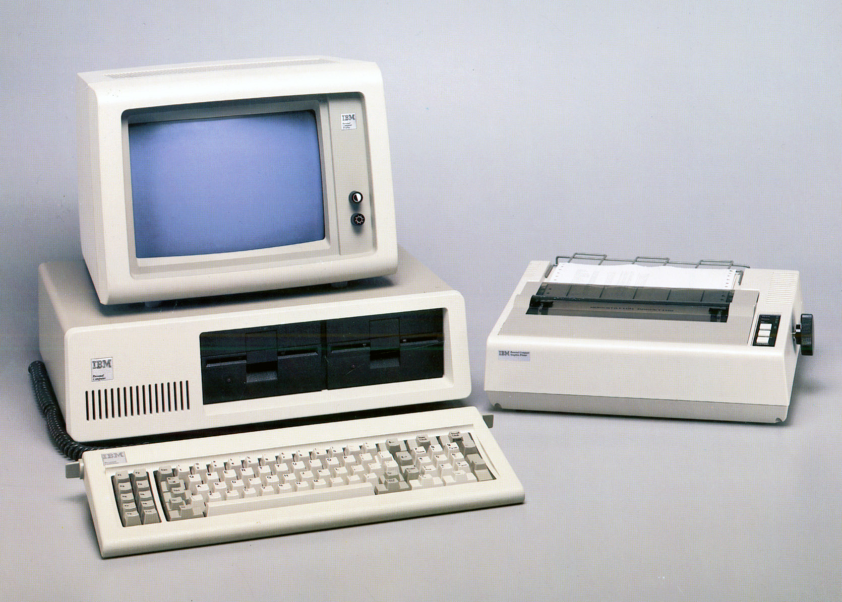
Ben Hardwidge travels back to August 1981, when IBM released its Personal Computer 5150 and the PC was born.
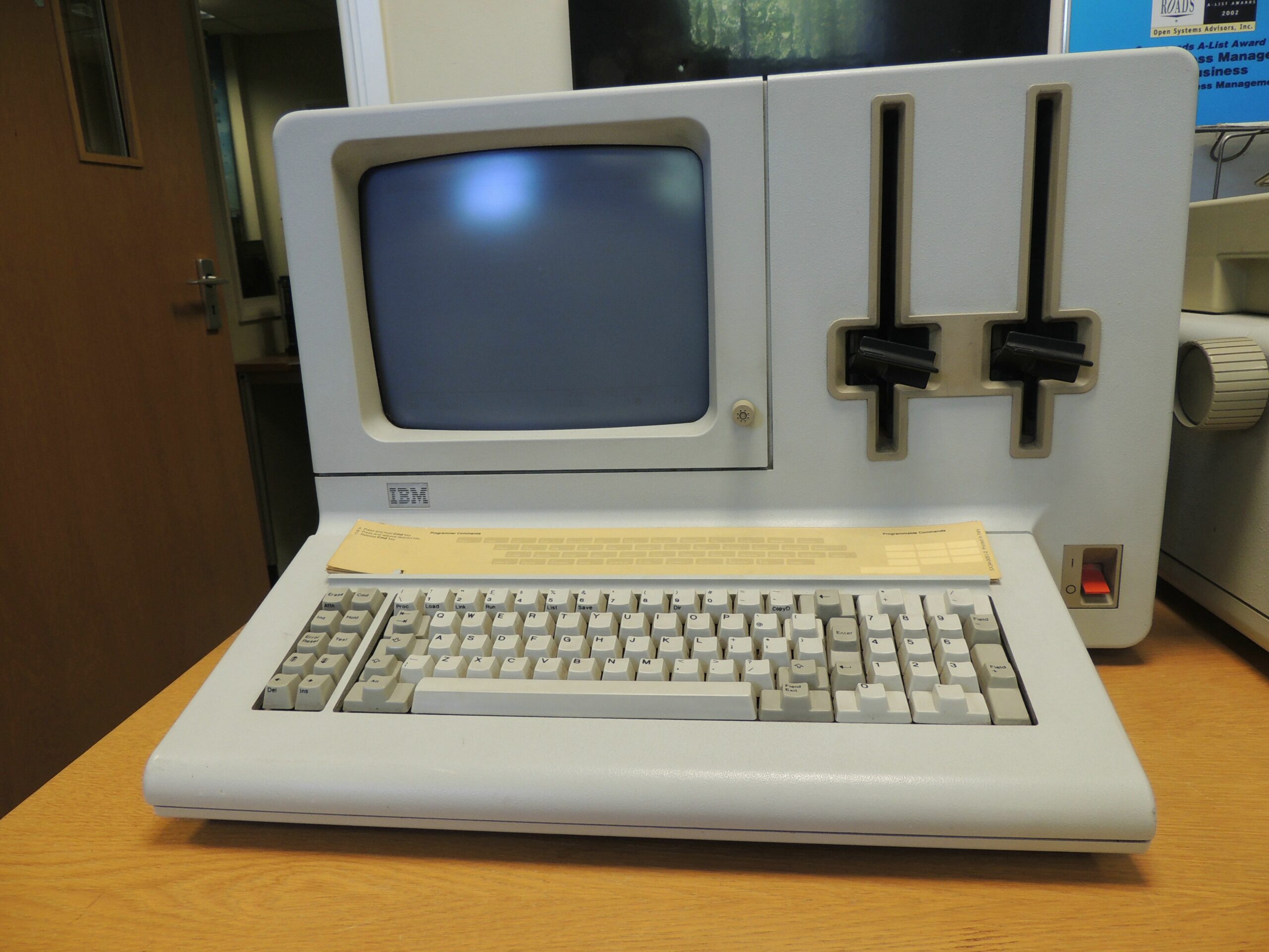
A big ape had only just started lobbing barrels at a pixelated Mario in Donkey Kong arcade machines, Duran Duran’s very first album had just rolled off the vinyl presses and Roger Federer was just four days old. In this time, the UK was even capable of winning Eurovision with Bucks Fizz. It’s August 1981, and IBM has just released the foundation for the PCs we know and love today, the PC 5150.
‘By the late 1970s the personal computer market was maturing rapidly from the many build-it-yourself hobbyist kits to more serious players like Apple, Commodore and Tandy,’ retired IBM veteran Peter Short tells us. ‘As people realised the greater potential for personal computers in business as well as at home, pressure grew on IBM to enter the market with their own PC.’
Short is now a volunteer at IBM’s computer museum in Hursley, which holds a huge archive of the company’s computing machines and documentation, from Victorian punch card machines to the company’s personal computers. We ask him if it felt like the beginning of a new era when the PC was first launched 40 years ago. ‘Yes,’ he says, ‘but probably not the beginning of something so huge that its legacy lives on today.’
At this time, the home computer market was really starting to take off, with primitive 8-bit computers, such as the Sinclair ZX80 and Commodore VIC-20, enabling people at home to get a basic computer that plugged into their TV. At the other end of the scale, large businesses had huge mainframe machines that took up entire rooms, connected to dumb terminals.
There was clearly room for a middle ground. IBM was going to continue producing mainframes and terminals for many years yet, but it also wanted to create a powerful, independent machine that didn’t need a mainframe behind it, and that didn’t cost an exorbitant amount of money.
The PC 5150’s launch price of $1,565 US (around £885 ex VAT) for the base spec in 1981 equates to around £3,469 ex VAT in today’s money. That’s still very far from what we’d call cheap, but it was a colossal price drop compared with IBM’s System/23 Datamaster, an all-in-one computer (including screen) that had launched earlier the same year for $9,000 US – six times the price. And even that was massively cheaper than some of IBM’s previous microcomputer designs, such as the 5100, which cost up to $20,000 US in 1975.
IBM needed to act quickly. Commodore had already got a foothold in this market several years earlier with the PET, for example, and IBM realised that it couldn’t spend its usual long development time on the project. The race was on, with the project given a one-year time frame for completion.
‘At the time, IBM was more geared up to its traditional, longer-term development processes,’ explains Short. ‘But it eventually realised that, with a solid reputation in the marketplace, it was time to look for a way to do fast-track development that would not produce a machine three, four or five years behind its competitors.’
Processors and coprocessors
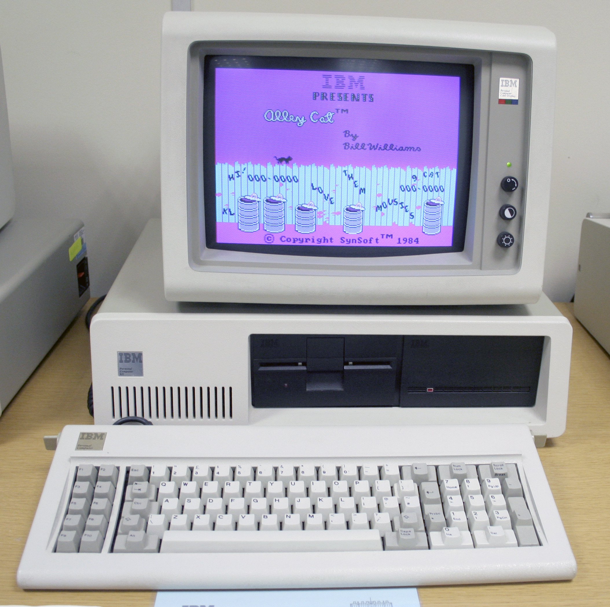
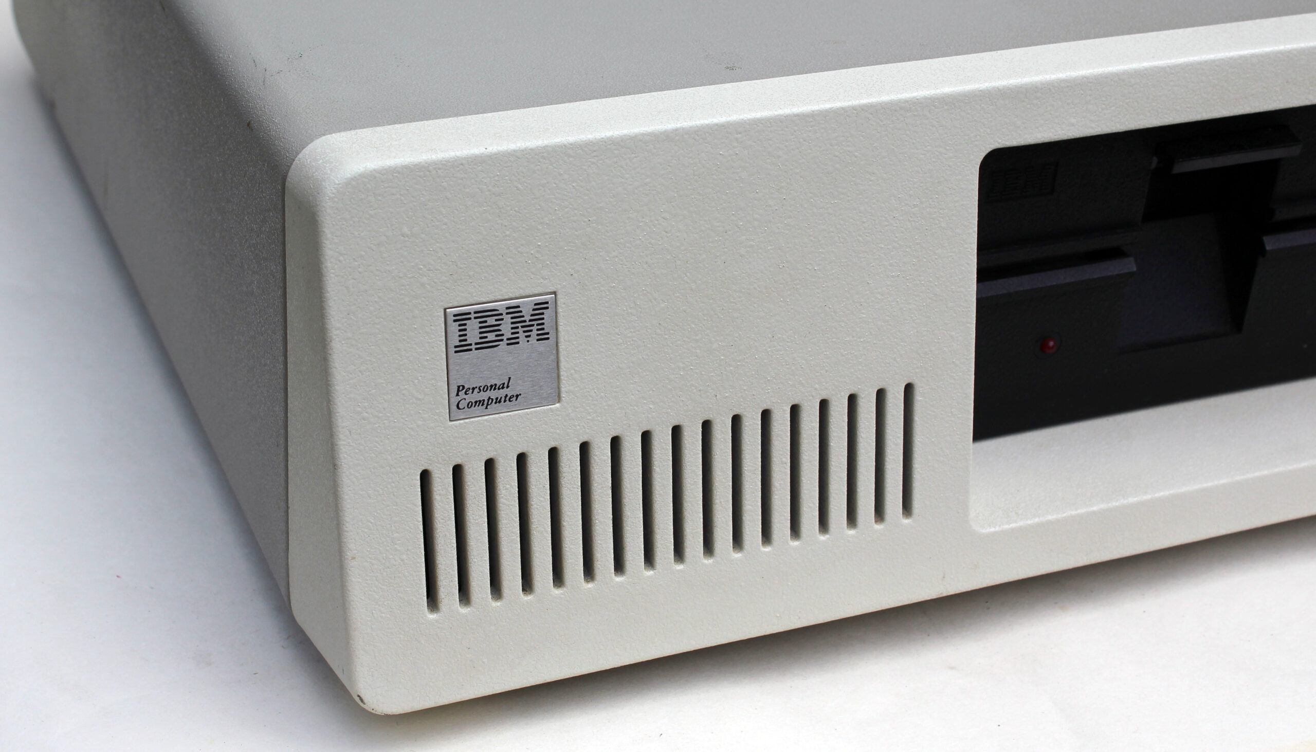
We opened up a PC 5150 for this feature, so we could have a good look at the insides and see how it compares with PCs today. It’s hugely different from the gaming rigs we see now, but there are still some similarities. For starters, the floppy drive connects to the PSU with a 4-pin Molex connector, still seen on PC PSU cables today. The PC was also clearly geared towards expansion from the start.
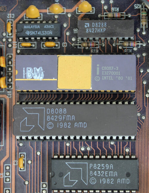
The ticking heart of the box is a 4.77MHz 8088 CPU made by AMD – Intel had given the company a licence to produce clones of its chips so that supply could keep up with demand. It’s for this reason that AMD still has its x86 licence and can produce CPUs for PCs today, but at this point, the two companies weren’t really competitors in the way they are now. To all intents and purposes, an AMD 8088 was exactly the same as an Intel one, and PCs generally came with whichever one was in best supply at the time of the machine’s manufacture.
The CPU itself is an interesting choice. It’s a cut-down version of Intel’s 8086 CPU that it had launched in 1978. The 8088 has the same execution unit design as the 8086, but has an 8-bit external data bus, compared with the 8086’s 16-bit one. As with today’s PCs, the CPU is also removable and replaceable, but in the case of the PC 5150, it’s in a long dual in-line package (DIP) with silver pins, rather than a square socket.
Immediately above the CPU sits another DIP socket for an optional coprocessor. At this point in time, the CPU was only an integer unit with no floating point processor. This was generally fine in an era when most software didn’t overly deal with decimal points, but you had the option to add an 8087 coprocessor underneath it. This worked as an extension of the 8088 CPU. ‘Adding the 8087 allowed numeric calculations to run faster for those users who needed this feature,’ explains Short.
The decision to use a CPU based on Intel’s x86 instruction set laid the machine code foundation for future PCs, and hasn’t changed since. Comparatively, Apple’s Mac line-up has had a variety of instruction sets, including PowerPC, x86 and now Arm. Nvidia might be making big noises about the future of Arm in the PC, but the x86 instruction set has stood its ground on the PC for 40 years now.
IBM itself has also dabbled with different instruction sets, including its own 801 RISC processor. Why did it go with Intel’s CISC 8088 CPU for the first PC? The answer, according to Short, is mainly down to time and a need to maintain compatibility with industry standards at the time.
‘The first prototype IBM computer using RISC architecture only arrived in 1980 and required a compatible processor,’ he explains. ‘In order to complete the 5150 development in the assigned one-year time frame, IBM had already decided to go with industry-standard components, and there was existing experience with the 8088 from development by GSD (General Systems Division) of the System/23. RISC required the IBM 801 processor, but the decision was made to go with industry standard components.’
Expansion slots
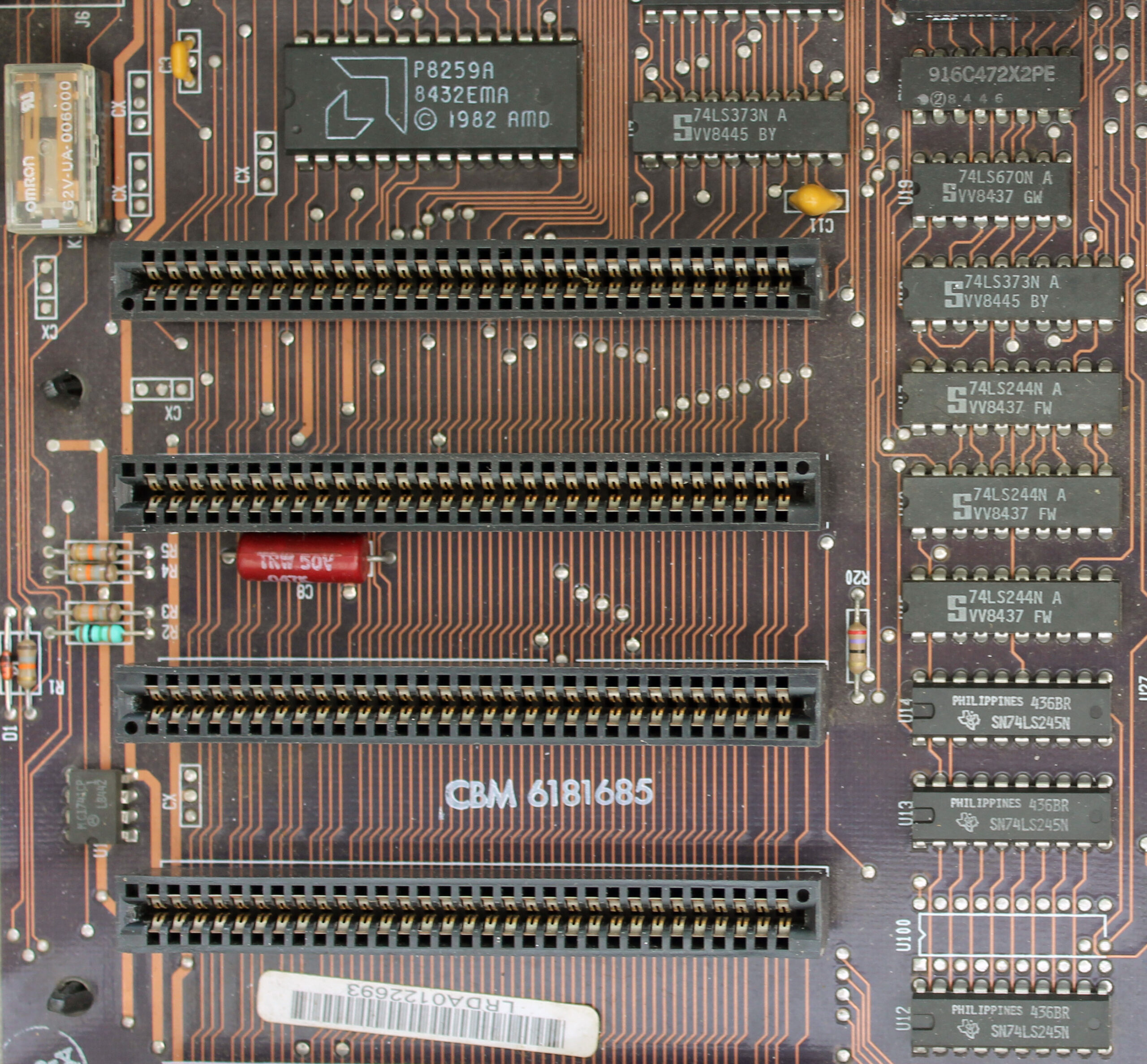
In addition to the ability to add a coprocessor, the IBM PC 5150’s motherboard also contains five expansion slots, with backplate mounts at the back of the case, just like today’s PCs. Three of the slots in our sample were also filled.
One card is actually two PCBs sandwiched together – it’s a dual-monitor video card with the ability to output to both an MDA screen and a CGA screen simultaneously (more on these standards later) – each standard required a separate PCB on this card – there’s a composite TV output in addition to the pair of 9-pin monitor outputs as well. Bizarrely, this card also doubles as a parallel port controller, with a ribbon cable providing a 25-pin port. It’s typical of the Wacky Races vibe seen on cards at the time, with multiple features shoehorned into one expansion slot.
Similarly, there’s also a 384KB memory expansion card, which also doubles as a serial I/O card, with a 25-pin port on the backplate. The final card is an MFM storage controller for the 5.25in floppy drive at the front of the machine.
Although the PC was clearly built with expansion in mind, Short points out that ‘IBM was not the first to introduce expansion slots. As far back as 1976, Altair produced the 8800b with an 18-slot backplane, the Apple II also featured slots from 1977 and there was also an expansion bus on the BBC Micro from 1981. No doubt market research and competitive analysis showed that this approach would provide additional flexibility and options without having to redesign the motherboard’.
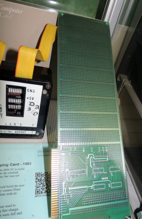
Interestingly, though, Short also says IBM was keeping an ‘eye on the hobby market. A standard bus with expansion slots would allow users to create their own peripherals. IBM even announced a Prototyping Card, with an area for standard bus interface components and a larger area for building your own design’. It’s a far cry from the heavily populated PCI-E cards with complex machine soldering that we see today.
Memory
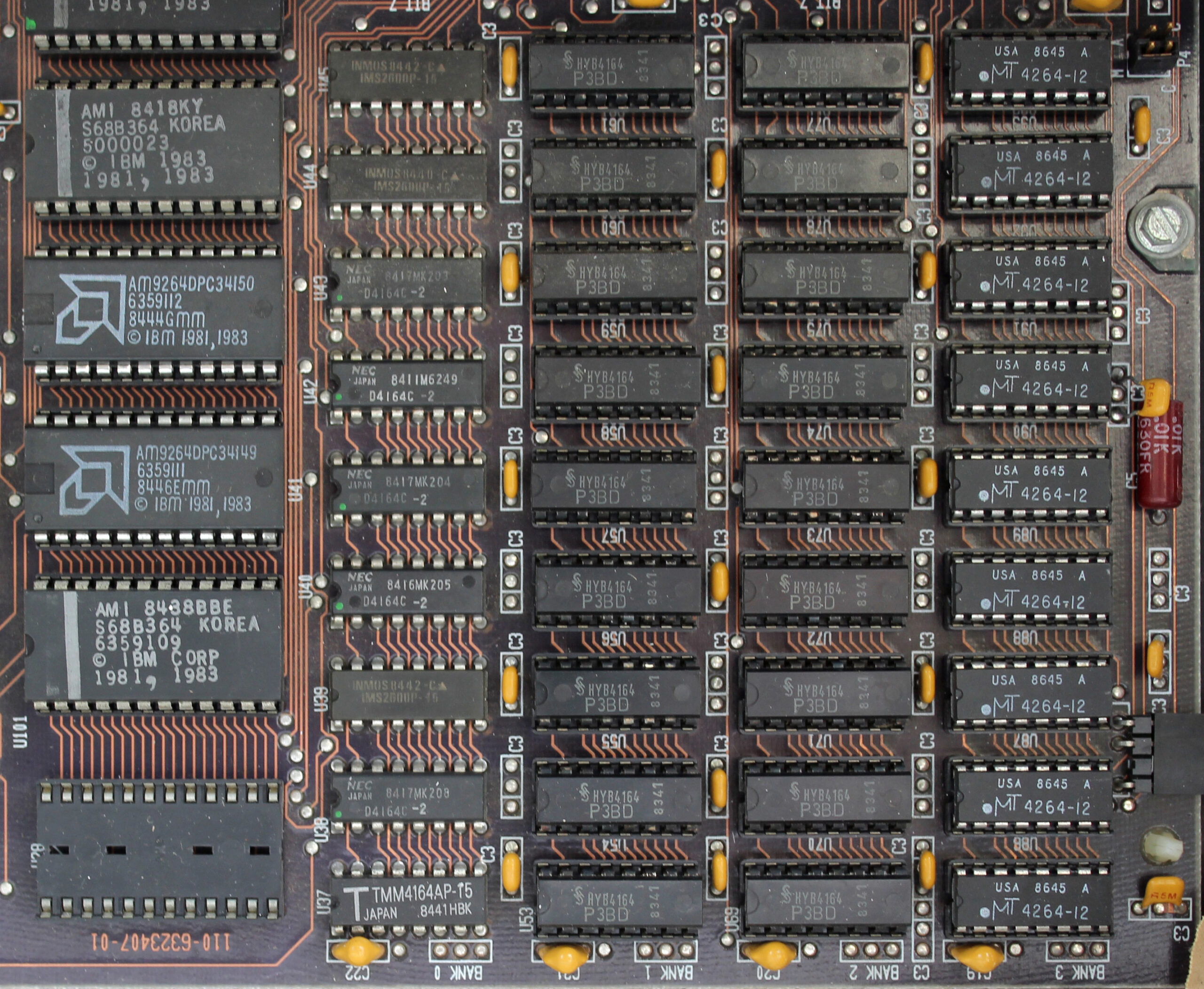
That 384KB memory card shows a very different approach to memory expansion than the tidy modules we have today. Believe it or not, at launch, the PC 5150 base spec came with just 16KB of memory (a millionth of the amount of memory in today’s 16GB machines), which was supplied in the form of DRAM chips on the bottom right corner of the motherboard.
The top spec at launch increased that amount to 64KB, although you could theoretically also install the DRAM chips yourself if you could get hold of exactly the right spec of chips and set it up properly. The chips on the motherboard are split into four banks, each with nine chips (eight bits and one parity bit). In the original spec, the 16KB configuration filled one bank, while the 64KB configuration filled all four banks with 16KB of memory each.
A later revision of the motherboard expanded this to 64KB as the base spec with one bank filled, and 256KB with all four banks filled (this is the spec in our sample). If you then added a 384KB memory card, such as the one in our sample, you ended up with 640KB of memory – the maximum base memory addressable by PCs at this time.
Graphics and displays
As we previously mentioned, our PC 5150 sample has a dual-monitor card, which supports both the display standards available to the IBM PC at launch. A Mono Display Adaptor (MDA) card could only output text with no graphics, while a Color Graphics Adaptor (CGA) card could output up to four colours (from a palette of 16) at 320 x 200, or output monochrome graphics at 640 x 200.
However, as Short notes, ‘the PC was announced with the mono 5151 display in 1981. The CGA 5153 was not released until 1983’. Even if you had a CGA card in your PC 5150, if you used the original monitor, you wouldn’t be able to see your graphics in colour. Seeing colour graphics either required you to use the composite output or a third-party monitor.
‘Once the colour monitor became available,’ says Short, ‘it could either be attached as the sole display with its own adaptor card, or equipped with both a mono and colour adaptor card, and could be attached together with a mono screen. Now you could run your spreadsheet on the mono monitor and display output graphics in colour.’
There’s an interesting connection with the first PC monitors and the legacy of IBM’s computing history too. When we interviewed the Hursley Museum’s curator Terry Muldoon (who has now sadly passed away) in 2011, he told us the reason why the first PC monitors had 80 columns. ‘It’s because it’s the same as punch cards,’ he said. ‘All green-screen terminals had 80 columns, because they were basically emulating a punch card.’
Storage
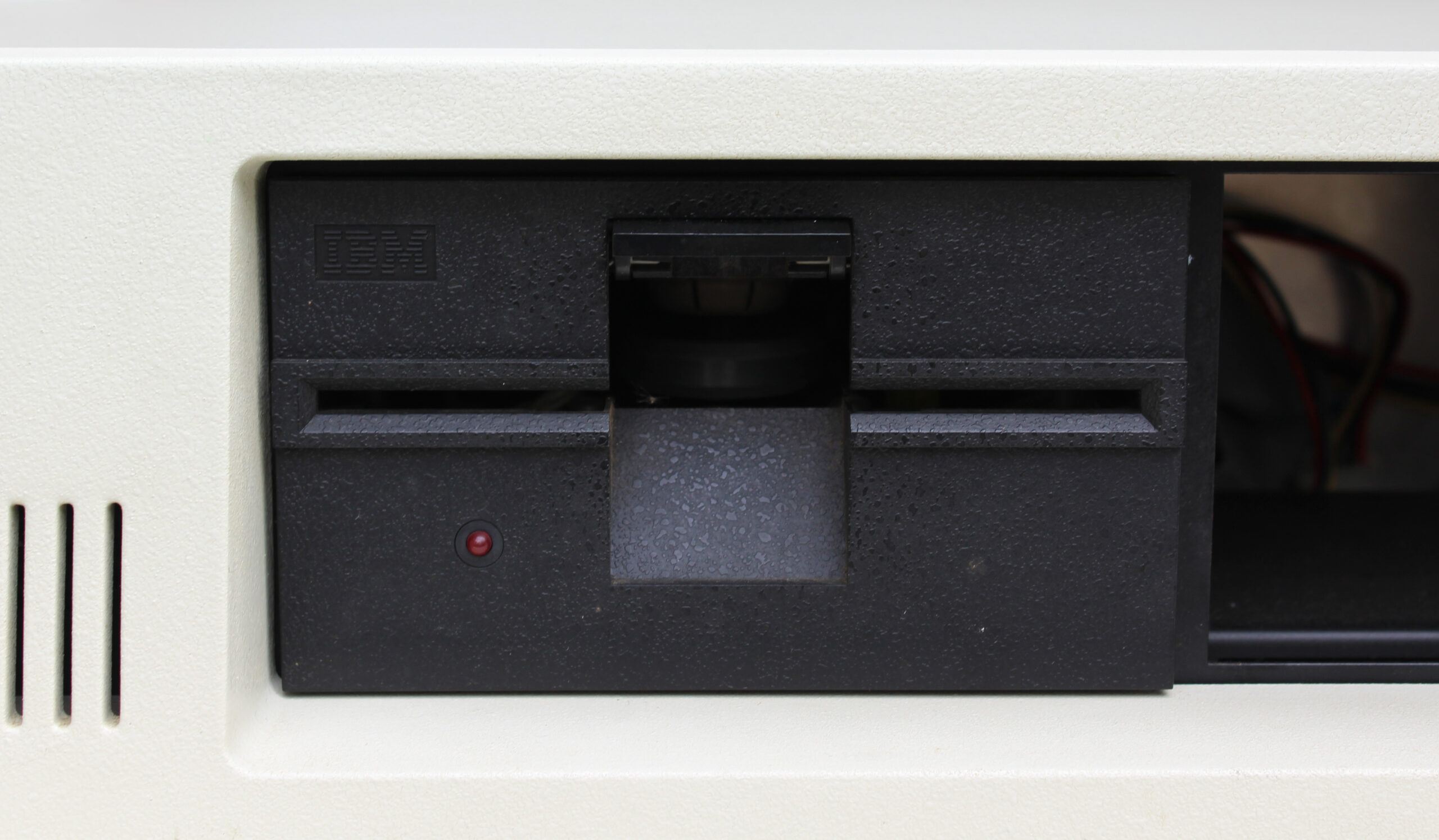
Storage is another area where the PC is at a crossroads between new tech. As standard, the PC 5150 came with a single 5.25in double-density floppy drive, with 360KB of storage space on each disk. There was the option to add a second floppy drive in the empty drive bay, but there was no hard drive at launch.
‘The first hard drive for microcomputers did not arrive until 1980 – the Seagate ST506 with a capacity of 5MB,’ explains Short. ‘By that time, the PC specifications had already been agreed and the hardware development team in Boca Raton was in full swing. The requirement was for a single machine developed within a one-year time frame.
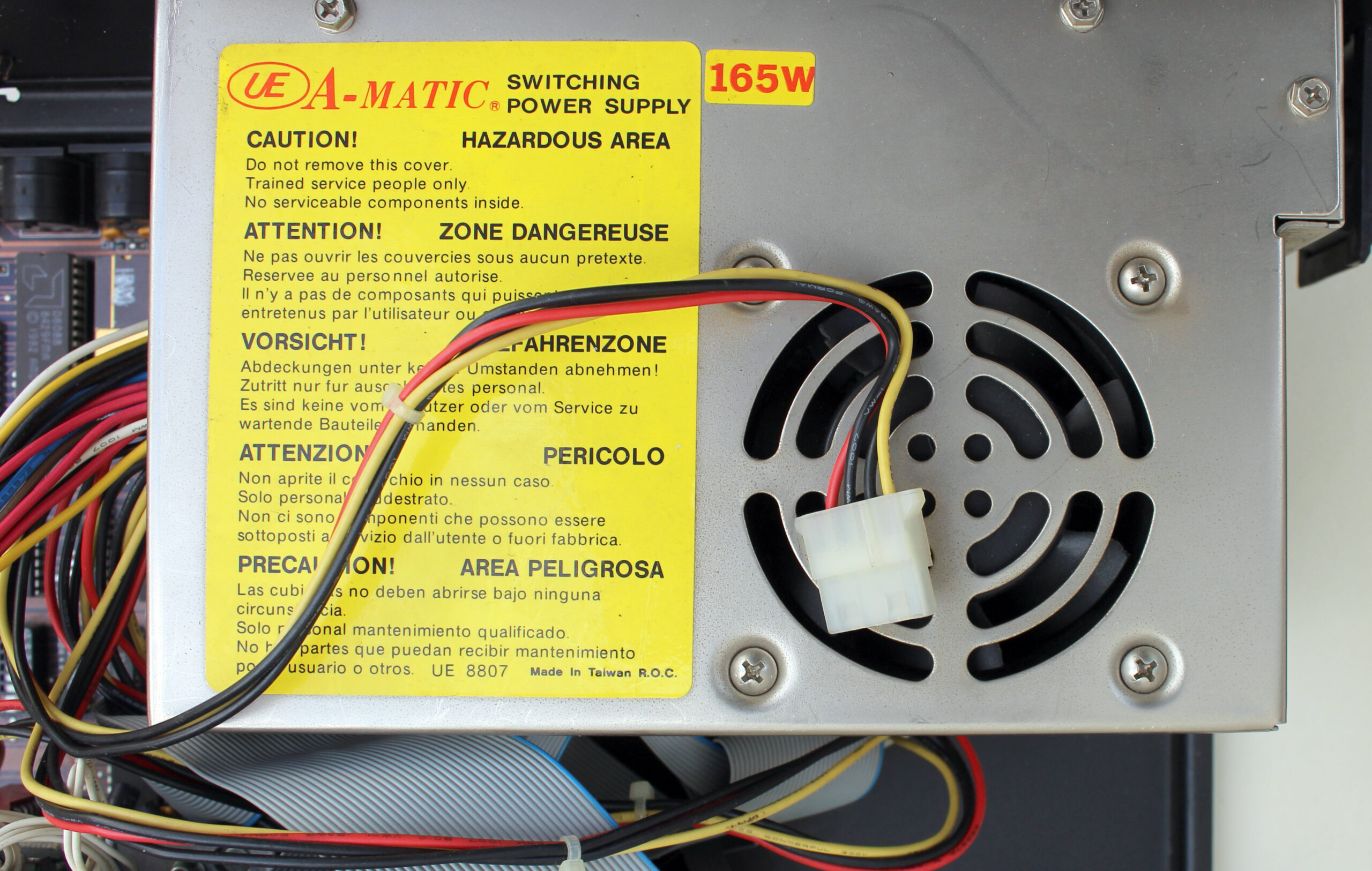
‘A small company called Microsoft was also developing the first version of DOS under sub-contract. The 5150 BIOS therefore had no hard disk support – DOS 1.0 and 1.1 are the same. The power supply selected for the 5150 wasn’t beefy enough at 63W to power the 5150 and a hard drive.’
Later versions of the 5150, such as our sample, came with a 165W PSU, and future DOS versions enabled you to run a hard drive, but it wasn’t until the IBM PC 5160 XT in 1983 that there was a hard drive option with an IBM PC as standard.
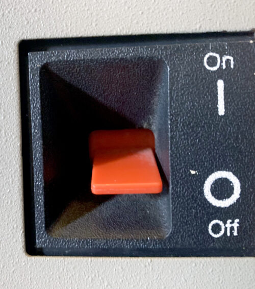
The PSU also connects to a massive red switch power switch on the side, which is very different from the delicate touch-buttons we have today. You had to literally flip a switch to power on the first PCs. This was another legacy of IBM’s past – a time when, if a machine needed to be shut down drastically, you would ‘BRS it’ – BRS stands for big red switch.
The back of the PC 5150 also alludes to another form of storage. There are two DIN sockets on the back, one of which is labelled for the keyboard – the other is labelled ‘cassette’. ‘It was common at the time to provide software on cassette tapes, which could also be used to store user written programmes,’ says Short. ‘My own Radio Shack TRS80 in 1979 used this method. A standard cassette tape machine such as the Philips could be connected through this socket.’
Software support
This brings us neatly to the subject of software support. We’re now used to graphical user interfaces such as Windows as standard, but in 1981 Microsoft was a small company, which had developed a popular version of the BASIC programming language.
‘Microsoft Basic was already very much an industry standard by 1980,’ says Short. ‘It was Microsoft’s first product. This fitted with the concept of using industry standard components. IBM chose to sub-contract its operating system development to Microsoft, perhaps for this reason. Again, the compressed development schedule influenced these decisions.’
Terry Muldoon gave us some more insight into the development of the PC’s first operating system, IBM PC DOS 1.0, when we spoke to him in 2011. ‘The story I heard is that basically IBM needed an operating system,’ he said, ‘and IBM didn’t have time to write one – that’s the story. So they went out to various people, including Digital Research for CPM, but Digital Research didn’t return the call. Bill Gates did, but he didn’t have an operating system, so he went down the street and bought QDOS.
‘The original DOS was a tarted-up QDOS, supplied to IBM as IBM Personal Computer DOS, and Gates was allowed to sell Microsoft DOS (MS-DOS). And they carried on for many years with exactly the same numbers, so 1.1 was DOS 1 but with support for us foreigners, then we went to DOS 2 with support for hard disks, DOS 2.1 for the Junior, DOS 3 for the PC80 and so on.’
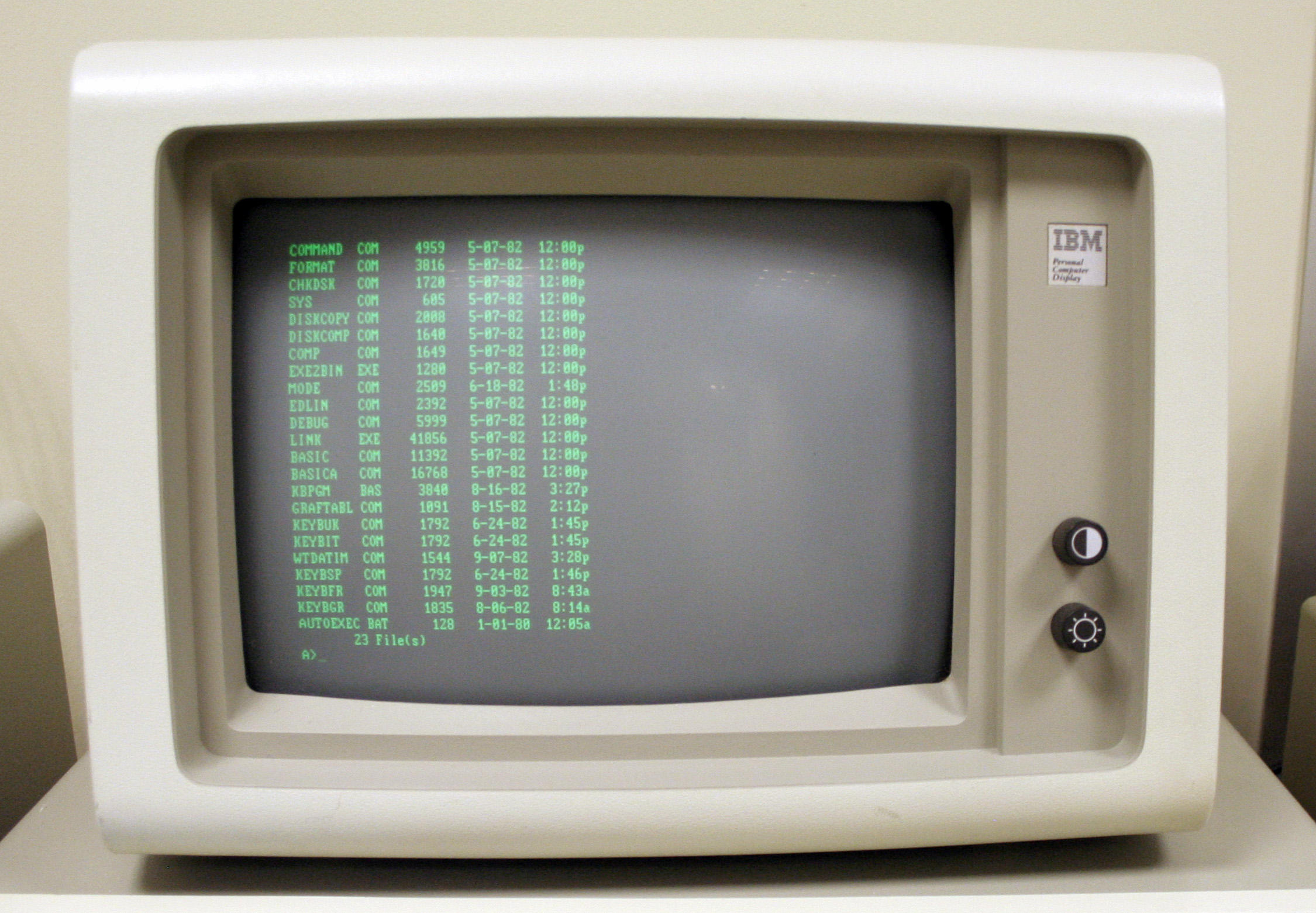
You can have a play with DOS 1.0 on an emulated PC 5150 at custompc.co.uk/5150, and it’s a very basic affair. Even if you’ve used later versions of DOS, there are some notable absences, such as the inability to add ‘/w’ to ‘dir’ to spread out the directory of your A drive across the screen, rather than list all the files in a single column.
What’s also striking is the number of BASIC files supplied as standard, which can be run on the supplied Microsoft BASIC. One example is DONKEY.BAS, a primitive top-down game programmed by Bill Gates and Neil Konzen, where you move a car from left to right to avoid donkeys in the road (really). What’s more, this game specifically requires your PC to have a CGA card and to run BASIC in advanced mode – you couldn’t run it on the base spec.
A future standard
With its keen pricing compared with previous business computers, the IBM PC 5150 was well received in the USA, paving the way for a launch in the UK in 1983, along with DOS 1.1 and the option for a colour CGA monitor. Clone machines from companies such as Compaq soon followed, claiming (usually, but not always, rightly) to be ‘IBM PC compatible’, and the PC started to become the widespread open standard that it is today. Was this intentional on IBM’s part?
‘Industry standard components, an expansion bus and a prototyping card would naturally lead to an open standard,’ says Short. ‘Not publishing the hardware circuitry would make it difficult to capture the imagination of “home” developers. Open architecture was part of the original plan.’
Muldoon wasn’t so sure when we asked him back in 2011. ‘Now where did IBM make the mistake with DOS?’ He asked. ‘This is personal opinion, but IBM allowed Bill Gates to retain the intellectual property. So we’ve now got an Intel processor – the bus was tied to Intel – and another guy owns the operating system, so you’ve already lost control of all of your machine in about 1981. The rest is history.
‘The only bit that IBM owned in the IBM PC was the BIOS, which was copyright. So, to make a computer 100 per cent IBM compatible, you had to have a BIOS. There were loads of software interrupts in that BIOS that people used, such as the timer tick, which were really useful. You get that timer tick and you can get things to happen, so you have to be able to produce something that hits the timer tick, because the software needs it.’
Rival computer makers could circumvent the copyright of the BIOS by examining what it did and attempting to reverse-engineer it. Muldoon explained the process to us.
‘The way people did it is: with one group of people, say: “this is what it does”, and another group of people take that specification, don’t talk to them, and then write some code to make it do that – that’s called “clean room”. So one person documents what it does, and another person now writes code to do it – in other words, nobody has copied IBM code, and there’s a Chinese wall between these two people.
‘What some of the clone manufacturers did is, because we published the BIOS, they just copied it. Now, the BIOS had bugs in it, and we knew they’d copied our BIOS because they’d copied the bugs as well. This was only the small companies that came and went. Phoenix produced a clean room BIOS, so if you used a Phoenix chip in your clones, you were clean.’
Of course, any self-contained personal computer can technically be called a PC. Peter Short describes a PC as a machine that ‘can be operated directly by an end user, from beginning to end, and is general enough in its capabilities’. It doesn’t require an x86 CPU or a Microsoft OS. In fact, there was and still is a variety of operating systems available to x86 PCs, from Gem and OS/2 in the early days, through to the many Linux distributions available now.
However, the PC as we generally know it, with its x86 instruction set and Microsoft OS, started with the PC 5150 in 1981. Storage and memory capacities have hugely increased, as have CPU clock frequencies, but the basic idea of a self-contained box with a proper CPU, enough memory for software to run, its own storage and a display output, as well as room to expand with extra cards, started here. Thank you, IBM.
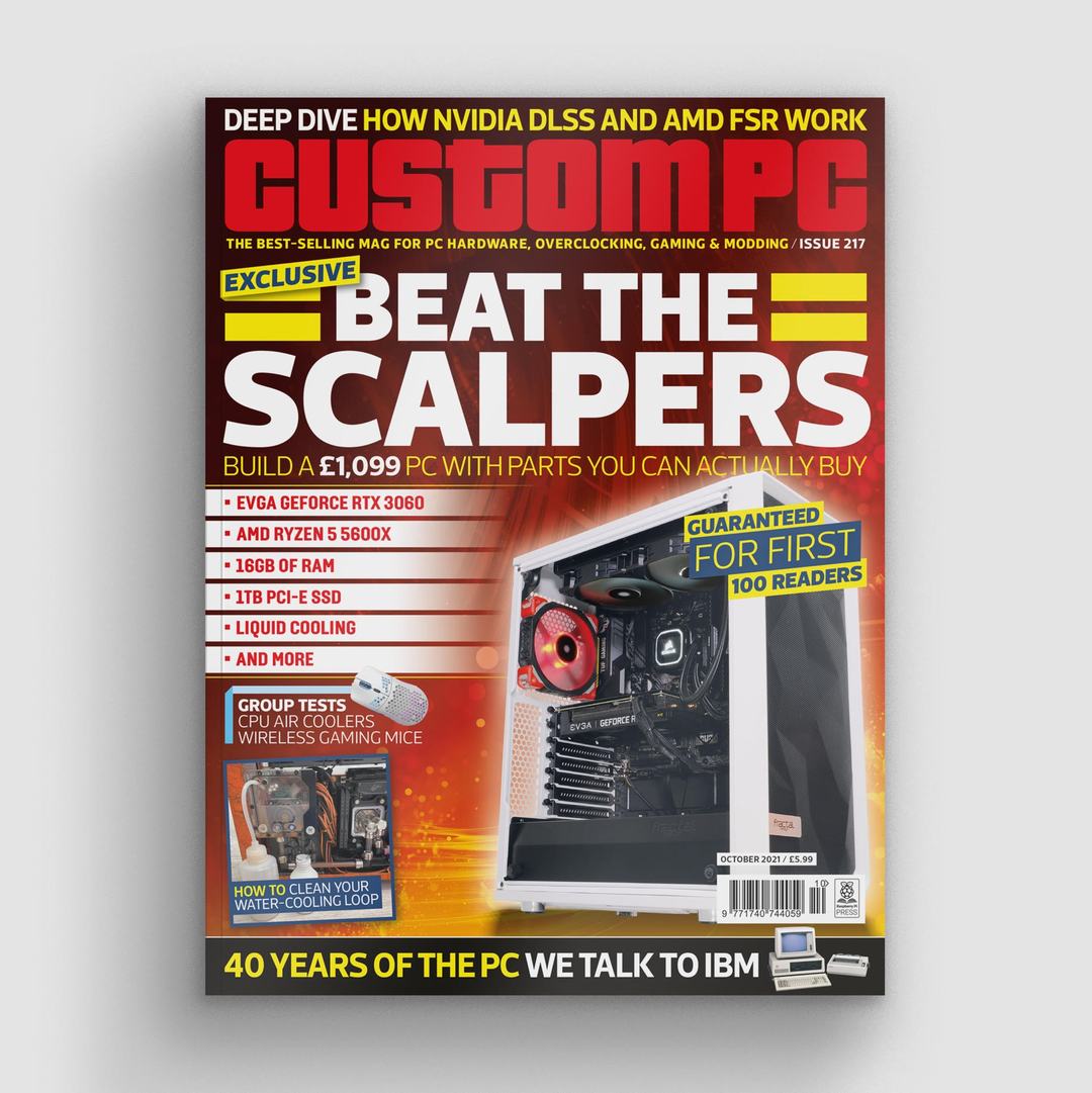
Custom PC issue 217 out NOW!
You can read more features like this one in Custom PC issue 217, available directly from Raspberry Pi Press — we deliver worldwide.
And if you’d like a handy digital version of the magazine, you can also download issue 217 for free in PDF format.
The post 40 years of the PC appeared first on Raspberry Pi.