Post Syndicated from corbet original https://lwn.net/Articles/943751/
The
6.5.2,
6.4.15,
6.1.52, and
5.15.131
stable kernels have been released; each contains another set of important
fixes.
Post Syndicated from Marvin Gersho original https://aws.amazon.com/blogs/big-data/build-streaming-data-pipelines-with-amazon-msk-serverless-and-iam-authentication/
Currently, MSK Serverless only directly supports IAM for authentication using Java. This example shows how to use this mechanism. Additionally, it provides a pattern creating a proxy that can easily be integrated into solutions built in languages other than Java.
The rising trend in today’s tech landscape is the use of streaming data and event-oriented structures. They are being applied in numerous ways, including monitoring website traffic, tracking industrial Internet of Things (IoT) devices, analyzing video game player behavior, and managing data for cutting-edge analytics systems.
Apache Kafka, a top-tier open-source tool, is making waves in this domain. It’s widely adopted by numerous users for building fast and efficient data pipelines, analyzing streaming data, merging data from different sources, and supporting essential applications.
Amazon’s serverless Apache Kafka offering, Amazon Managed Streaming for Apache Kafka (Amazon MSK) Serverless, is attracting a lot of interest. It’s appreciated for its user-friendly approach, ability to scale automatically, and cost-saving benefits over other Kafka solutions. However, a hurdle encountered by many users is the requirement of MSK Serverless to use AWS Identity and Access Management (IAM) access control. At the time of writing, the Amazon MSK library for IAM is exclusive to Kafka libraries in Java, creating a challenge for users of other programming languages. In this post, we aim to address this issue and present how you can use Amazon API Gateway and AWS Lambda to navigate around this obstacle.
Compared to the traditional authentication methods like Salted Challenge Response Authentication Mechanism (SCRAM), the IAM extension into Apache Kafka through MSK Serverless provides a lot of benefits. Before we delve into those, it’s important to understand what SASL/SCRAM authentication is. Essentially, it’s a traditional method used to confirm a user’s identity before giving them access to a system. This process requires users or clients to provide a user name and password, which the system then cross-checks against stored credentials (for example, via AWS Secrets Manager) to decide whether or not access should be granted.
Compared to this approach, IAM simplifies permission management across AWS environments, enables the creation and strict enforcement of detailed permissions and policies, and uses temporary credentials rather than the typical user name and password authentication. Another benefit of using IAM is that you can use IAM for both authentication and authorization. If you use SASL/SCRAM, you have to additionally manage ACLs via a separate mechanism. In IAM, you can use the IAM policy attached to the IAM principal to define the fine-grained access control for that IAM principal. All of these improvements make the IAM integration a more efficient and secure solution for most use cases.
However, for applications not built in Java, utilizing MSK Serverless becomes tricky. The standard SASL/SCRAM authentication isn’t available, and non-Java Kafka libraries don’t have a way to use IAM access control. This calls for an alternative approach to connect to MSK Serverless clusters.
But there’s an alternative pattern. Without having to rewrite your existing application in Java, you can employ API Gateway and Lambda as a proxy in front of a cluster. They can handle API requests and relay them to Kafka topics instantly. API Gateway takes in producer requests and channels them to a Lambda function, written in Java using the Amazon MSK IAM library. It then communicates with the MSK Serverless Kafka topic using IAM access control. After the cluster receives the message, it can be further processed within the MSK Serverless setup.
You can also utilize Lambda on the consumer side of MSK Serverless topics, bypassing the Java requirement on the consumer side. You can do this by setting Amazon MSK as an event source for a Lambda function. When the Lambda function is triggered, the data sent to the function includes an array of records from the Kafka topic—no need for direct contact with Amazon MSK.
This example walks you through how to build a serverless real-time stream producer application using API Gateway and Lambda.
For testing, this post includes a sample AWS Cloud Development Kit (AWS CDK) application. This creates a demo environment, including an MSK Serverless cluster, three Lambda functions, and an API Gateway that consumes the messages from the Kafka topic.
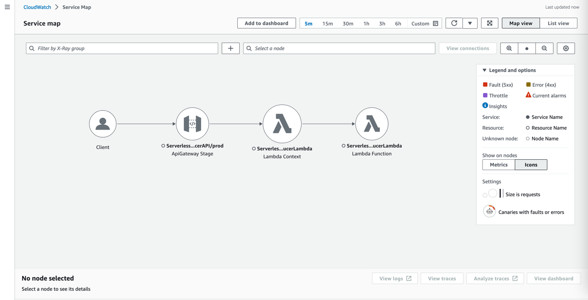
The following diagram shows the architecture of the resulting application including its data flows.
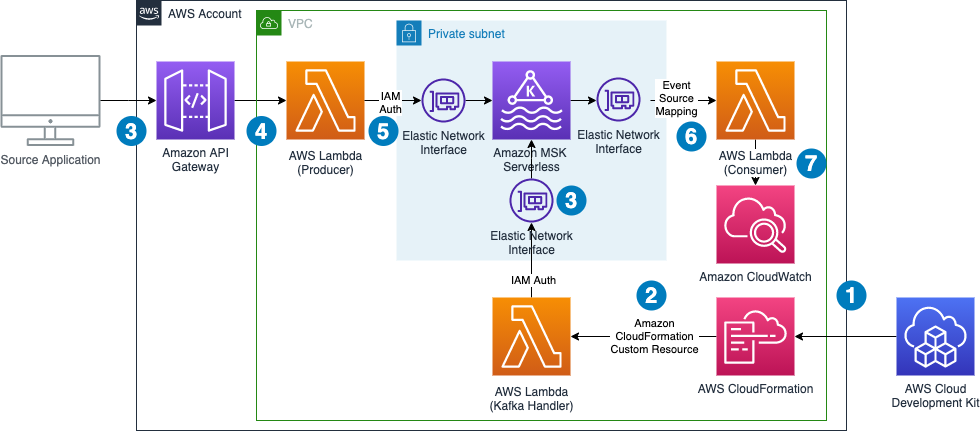
The data flow contains the following steps:
Note that we don’t need to worry about Availability Zones. MSK Serverless automatically replicates the data across multiple Availability Zones to ensure high availability of the data.
The demo additionally shows how to use Lambda Powertools for Java to streamline logging and tracing and the IAM authenticator for the simple authentication process outlined in the introduction.
The following sections take you through the steps to deploy, test, and observe the example application.
The example has the following prerequisites:
Complete the following steps to deploy the solution:
serverless-kafka-iac:To test the solution, we generate messages for the Kafka topics by sending calls through the API Gateway from our development machine or AWS Cloud9 environment. We then go to the CloudWatch console to observe incoming messages in the log files of the Lambda consumer function.
/serverless_kafka_iac/test_api.py: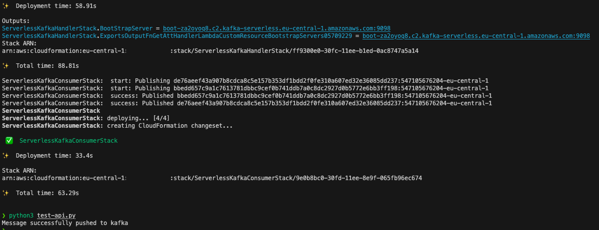
ServerlessKafkaConsumer.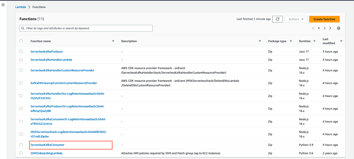
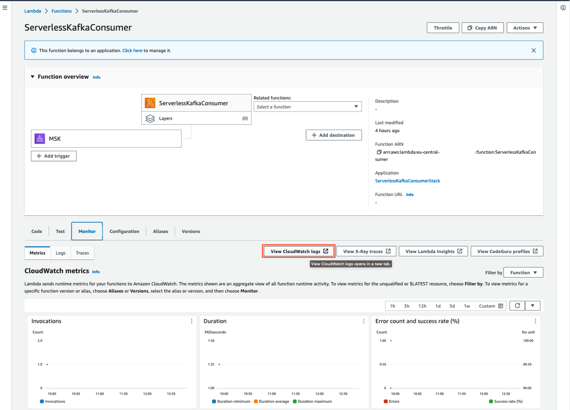
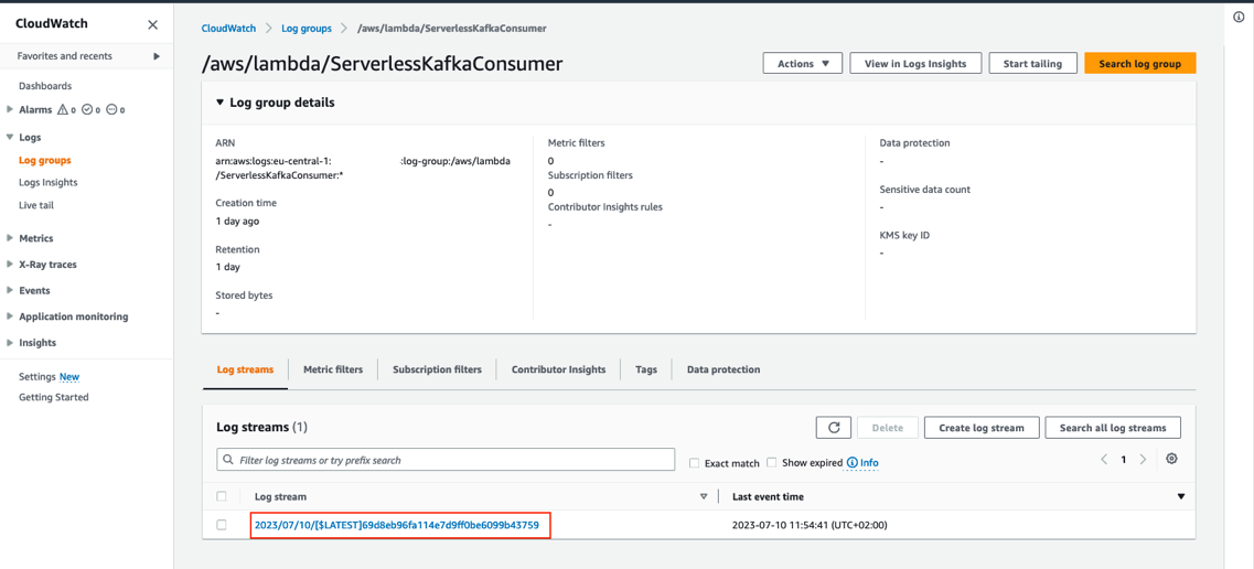
You can review the log entry of the received Kafka messages in the log of the Lambda function.

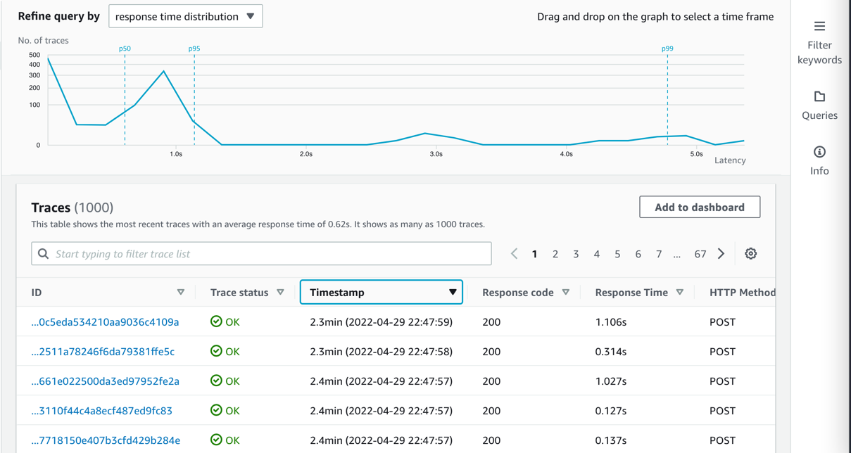
All components integrate with AWS X-Ray. With AWS X-Ray, you can trace the entire application, which is useful to identify bottlenecks when load testing. You can also trace method runs at the Java method level.
Lambda Powertools for Java allows you to shortcut this process by adding the @Trace annotation to a method to see traces on the method level in X-Ray.
To trace a request end to end, complete the following steps:
Kafka natively supports Java. To stay open, cloud native, and without third-party dependencies, the producer is written in that language. Currently, the IAM authenticator is only available to Java. In this example, the Lambda handler receives a message from an API Gateway source and pushes this message to an MSK topic called messages.
Typically, Kafka producers are long-living and pushing a message to a Kafka topic is an asynchronous process. Because Lambda is ephemeral, you must enforce a full flush of a submitted message until the Lambda function ends by calling producer.flush():
This post uses IAM authentication to connect to the respective Kafka cluster. For information about how to configure the producer for connectivity, refer to IAM access control.
Because you configure the cluster via IAM, grant Connect and WriteData permissions to the producer so that it can push messages to Kafka:
This shows the Kafka excerpt of the IAM policy, which must be applied to the Kafka producer. When using IAM authentication, be aware of the current limits of IAM Kafka authentication, which affect the number of concurrent connections and IAM requests for a producer. Refer to Amazon MSK quota and follow the recommendation for authentication backoff in the producer client:
Each MSK Serverless cluster can handle 100 requests per second. To reduce IAM authentication requests from the Kafka producer, place it outside of the handler. For frequent calls, there is a chance that Lambda reuses the previously created class instance and only reruns the handler.
For bursting workloads with a high number of concurrent API Gateway requests, this can lead to dropped messages. Although this might be tolerable for some workloads, for others this might not be the case.
In these cases, you can extend the architecture with a buffering technology like Amazon Simple Queue Service (Amazon SQS) or Amazon Kinesis Data Streams between API Gateway and Lambda.
To reduce latency, reduce cold start times for Java by changing the tiered compilation level to 1, as described in Optimizing AWS Lambda function performance for Java. Provisioned concurrency ensures that polling Lambda functions don’t need to warm up before requests arrive.
In this post, we showed how to create a serverless integration Lambda function between API Gateway and MSK Serverless as a way to do IAM authentication when your producer is not written in Java. You also learned about the native integration of Lambda and Amazon MSK on the consumer side. Additionally, we showed how to deploy such an integration with the AWS CDK.
The general pattern is suitable for many use cases where you want to use IAM authentication but your producers or consumers are not written in Java, but you still want to take advantage of the benefits of MSK Serverless, like its ability to scale up and down with unpredictable or spikey workloads or its little to no operational overhead of running Apache Kafka.
You can also use MSK Serverless to reduce operational complexity by automating provisioning and the management of capacity needs, including the need to constantly monitor brokers and storage.
For more serverless learning resources, visit Serverless Land.
For more information on MSK Serverless, check out the following:
 Philipp Klose is a Global Solutions Architect at AWS based in Munich. He works with enterprise FSI customers and helps them solve business problems by architecting serverless platforms. In this free time, Philipp spends time with his family and enjoys every geek hobby possible.
 Daniel Wessendorf is a Global Solutions Architect at AWS based in Munich. He works with enterprise FSI customers and is primarily specialized in machine learning and data architectures. In his free time, he enjoys swimming, hiking, skiing, and spending quality time with his family.
 Marvin Gersho is a Senior Solutions Architect at AWS based in New York City. He works with a wide range of startup customers. He previously worked for many years in engineering leadership and hands-on application development, and now focuses on helping customers architect secure and scalable workloads on AWS with a minimum of operational overhead. In his free time, Marvin enjoys cycling and strategy board games.
 Nathan Lichtenstein is a Senior Solutions Architect at AWS based in New York City. Primarily working with startups, he ensures his customers build smart on AWS, delivering creative solutions to their complex technical challenges. Nathan has worked in cloud and network architecture in the media, financial services, and retail spaces. Outside of work, he can often be found at a Broadway theater.
Post Syndicated from Bharav Patel original https://aws.amazon.com/blogs/big-data/use-the-reverse-token-filter-to-enable-suffix-matching-queries-in-opensearch/
OpenSearch is an open-source RESTful search engine built on top of the Apache Lucene library. OpenSearch full-text search is fast, can give the result of complex queries within a fraction of a second. With OpenSearch, you can convert unstructured text into structured text using different text analyzers, tokenizers, and filters to improve search. OpenSearch uses a default analyzer, called the standard analyzer, which works well for most use cases out of the box. But for some use cases, it may not work best, and you need to use a specific analyzer.
In this post, we show how you can implement a suffix-based search. To find a document with the movie name “saving private ryan” for example, you can use the prefix “saving” with a prefix-based query. Occasionally, you also want to match suffixes as well, such as matching “Harry Potter Goblet of Fire” with the suffix “Fire” To do that, first reverse the string “eriF telboG rettoP yrraH” with the reverse token filter, then query for the prefix “eriF”.
Text analysis involves transforming unstructured text, such as the content of an email or a product description, into a structured format that is finely tuned for effective searching. An analyzer enables the implementation of full-text search using tokenization, which entails breaking down a text into smaller fragments known as tokens, with these tokens commonly representing individual words. To implement a reversed field search, the analyzer does the following.
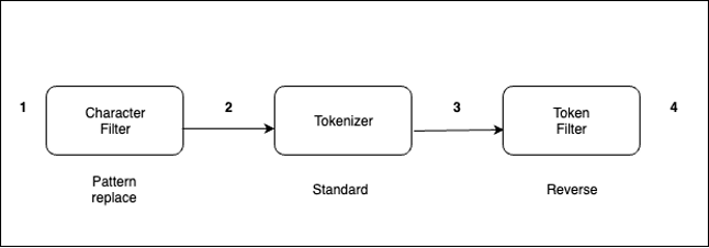
The analyzer processes text in the following order:
- with _. For example, from “My Driving License Number Is 123-456-789” to “My Driving License Number Is 123_456_789.”The standard analyzer (default analyzer) breaks down input strings into tokens based on word boundaries and removes most punctuation marks. For additional information about analyzers, refer Build-in analyzers.
Every document is a collection of fields, each having its own specific data type. When you create a mapping for your data, you create a mapping definition, which contains a list of fields that are pertinent to the document. To know more about index mappings refer to index mapping.
Let’s take the example of an analyzer with the reverse token filter applied on the text field.
reverse_title’ is derived from ‘title’ field for suffix search and original field ‘title’ will be used for normal search.reverse_title’ for “Fire”:The following code shows our results:
title’.The following code shows our result.
The query returns a document with the movie name “Harry Potter Goblet of Fire”.
If you’re curious to know how search works at high level, refer to A query, or There and Back Again.
In this post, you walked through how text analysis works in OpenSearch and how to implement suffix-based search using a reverse token filter effectively.
If you have feedback about this post, submit your comments in the comments section.
About the Authors
 Bharav Patel is a Specialist Solution Architect, Analytics at Amazon Web Services. He primarily works on Amazon OpenSearch Service and helps customers with key concepts and design principles of running OpenSearch workloads on the cloud. Bharav likes to explore new places and try out different cuisines.
Post Syndicated from Talks at Google original https://www.youtube.com/watch?v=7d2OIGPWpO0
Post Syndicated from jake original https://lwn.net/Articles/943619/
A recent discussion on the Python forum looked at a way to
protect module objects (and users) from mistaken attribute assignment and
deletion.
There are ways
to get the same effect today, but the mechanism that would be used causes a
performance penalty for an unrelated, and heavily used, action: attribute
lookup on modules. Back in 2017, PEP 562 (“Module __getattr__
and __dir__”) set the stage for adding magic methods to module objects; now
a new proposal would extend that idea to add __setattr__() and
__delattr__() to them.
Post Syndicated from Shuyin Zhao original https://github.blog/2023-09-06-how-to-build-an-enterprise-llm-application-lessons-from-github-copilot/
| If you want to build and scale an application using a large language model (LLM), this article’s for you. |
It took us three years to develop GitHub Copilot before we officially launched it to the general public. To go from idea to production, we followed three stages—find it, nail it, scale it—loosely based on the “Nail It, Then Scale It” framework for entrepreneurial product development.
Here’s how it breaks down:
Let’s get started.
Sometimes the hardest part about creating a solution is scoping down a problem space. The problem should be focused enough to quickly deliver impact, but also big enough that the right solution will wow users. Additionally, you want to find a problem where the use of an LLM is the right solution (and isn’t integrated to just drive product engagement).
Focus on a single problem, first. Rather than trying to address all developer problems with AI, we focused on one part of the software development lifecycle: coding functions in the IDE. At the time, most AI coding assistants could only complete a single line of code.
Balance product ambition with quality. While the GitHub Copilot team initially explored generating entire commits, the state of LLMs couldn’t support that function at a high enough quality at the time. Through additional testing, the team landed on code suggestions at the “whole function” level.
Product development with emerging tech, like generative AI, is often more of a winding path and a linear journey because so much is unknown and rapid advancements in the field can quickly open new doors. Building quick iteration cycles into the product development process allows teams to fail and learn fast. At GitHub, the main mechanism for us to quickly iterate is an A/B experimental platform.
According to Idan Gazit, Senior Director of Research for GitHub Next, “We have to design apps not only for models whose outputs need evaluation by humans, but also for humans who are learning how to interact with AI.”
We quickly found that a web interface was not the right canvas since it meant developers had to switch back and forth between their editor and the web browser. As a result, the team decided to focus on bringing GitHub Copilot to the IDE and making the AI capability modeless—or working in the background.
The developers on our team also noticed they often referenced multiple open tabs in the IDE while coding. This insight led them to experiment with a technique called neighboring tabs, where GitHub Copilot processes multiple files open in a developer’s IDE instead of just the single one the developer is working on. Neighboring tabs helped to increase the acceptance rates of GitHub Copilot’s suggestions by 5%.
Evaluate your testing tools. As our experiment continued, we had to scale our internal testing tools to be more versatile and powerful. While we initially relied on our own tools for testing, we ultimately switched to the Microsoft Experimentation Platform to optimize functionality based on the feedback and interaction at scale.
Avoid the sunk cost fallacy. This is when you’re reluctant to abandon a course of action because you’ve heavily invested in it—even when it’s clear switching gears would be more beneficial.
The GitHub and OpenAI teams initially believed every coding language would require its own fine-tuned AI model. But the field of generative AI was rapidly advancing, and our assumption turned out to be incorrect. In the end, OpenAI’s LLMs significantly improved and one model could handle a wide variety of coding languages and tasks.
Make a habit of revisiting old ideas. In a field that’s rapidly advancing, the functions that aren’t feasible with today’s LLMs might be possible with tomorrow’s.
In the beginning, we explored a chat interface for developers to ask coding questions. However, in early testing, users had much higher expectations for the capabilities and quality of coding suggestions than GitHub Copilot could deliver at the time. As a result, we deprioritized the feature. But as customers became familiar with AI chatbot following the emergence of ChatGPT and LLMs continued to evolve, an iterative chat experience, like GitHub Copilot Chat, became possible.
Early feedback and technical previews are key to driving product improvements and getting your application to GA. Below you’ll find the steps we took before launching the GitHub Copilot technical preview, how we managed the technical preview and optimized user feedback, and how we prepared our internal infrastructure to handle demand at scale.
For instance, when the GitHub Copilot team first decided to provide whole function coding suggestions, we also had to ensure output predictability and consistency, where the same prompt and context would produce the same suggestions from the AI model.
To achieve this, the team applied two strategies: changing the parameters to reduce the randomness of outputs and caching responses. Additionally, using cached responses instead of generating new responses to the same prompt not only reduced variability in suggestions, but it also improved performance.
Implement a waitlist for your technical preview. A waitlist allowed the GitHub Copilot team to manage questions, feedback, and comments—and ensure we could address them effectively. This approach also helped ensure we had a diverse set of early adopters across developers of varying experience levels to provide feedback.
While the GitHub team actively dogfooded GitHub Copilot to understand what the experience was like for developers, we also benefited from developers outside GitHub adding diverse feedback across real-world use cases. The GitHub Copilot team engaged and interacted with technical preview users early, often, and on the users’ preferred platforms. This allowed us to actively respond to issues and feedback in real time.
Commit to iterating as you scale. When GitHub Copilot became generally available, the team not only had to improve the product, but also its infrastructure. When we experimented with and quickly iterated GitHub Copilot, it worked directly with the OpenAI API. As the product grew, we scaled our use of Microsoft Azure’s infrastructure to ensure GitHub Copilot had the quality, reliability, and responsible guardrails of a large-scale, enterprise-grade product.
Define the product’s key performance metrics. To optimize GitHub Copilot, we used early developer feedback to identify the right performance metrics, such as code acceptance rate and, eventually, code retention rate (which measures how much of the original code suggestion is kept or edited by a developer).
Optimize costs. The team worked to optimize the costs of delivering GitHub Copilot suggestions while balancing developer impact. For instance, before we decided on using ghost text—the gray text that flashes one coding suggestion while you type—the tool would eagerly generate 10 suggestions and display them all at once. This incurred upfront compute costs for suggestions two through 10, when most people choose the first one. But it also created a user experience cost, because those 10 suggestions pulled developers out of their workflow and into an evaluation mindset. “It was like paying to calculate the results that appear on the second page of a search engine—and making that second page grab your attention—even though most folks end up using the top result,” Gazit says.
Optimizing costs is an ongoing project, and we’re exploring new ideas to reduce costs while improving the user experience.
Prioritize security and trust. Feedback during GitHub Copilot’s technical preview reinforced the importance of suggesting code that is secure. In response, the team integrated code security capabilities to filter out suggestions that could contain security vulnerabilities (e.g., SQL injections and hard coded credentials) and used natural language filters from Azure OpenAI Service to filter out offensive content.*
Allow your community to help you. At GitHub, we deeply valued our extensive developer community for feedback on our products and collaborating with them to improve our offerings. With GitHub Copilot, our developer community was critical to understanding the potential around AI—and some concerns, too.
For instance, the developer community was concerned that GitHub Copilot suggestions might match public code. In response, the GitHub Copilot team created a filter to block suggestions matching public source code in GitHub public repositories that were longer than 150 characters.
Based on community input, the GitHub Copilot team also developed a code reference tool that includes links to public code that may match GitHub Copilot suggestions, so developers can review potential matches (and relevant licensing information), and make informed choices.
Launch your product with product evangelists. Before launching the technical preview of GitHub Copilot in 2021, the team presented the prototype to influential members of the software developer community and GitHub Stars. This allowed us to launch the technical preview with an existing base of support and extend the preview’s reach to a broader range of users.
Get your product in front of individual users before going after businesses. The team decided to first sell licenses directly to developers, who would clearly benefit from an AI coding assistant. We paired this approach with a free trial program and monthly pricing, based on user survey findings that individuals prefer a simple and predictable subscription. Gaining traction among individual users helped to build a foundation of support and drive adoption at the enterprise level.
We’re still in the early days of generative AI, so we’re keeping close tabs on the demand and need for this new technology. While each company and product will need to define its own approach to building an LLM app, here are some key learnings from our product journey with GitHub Copilot:
Integrate experimentation and tight feedback loops into the design process. This is especially critical when working with LLMs, where outputs are probabilistic and most end users are just learning how to interact with AI models.
As you scale, continue to leverage user feedback and prioritize user needs. Doing so will ensure that your product is built to deliver consistent results and real value.
If you’re looking for a problem to solve with an LLM app, check out our post on how companies are boosting productivity with generative AI. You can also take lessons from how GitHub used GitHub Actions to help an AI nonprofit, Ersilia, disseminate AI models to advance pharmaceutical research in low- and middle-income countries.
The post How to build an enterprise LLM application: Lessons from GitHub Copilot appeared first on The GitHub Blog.
Post Syndicated from Milind Oke original https://aws.amazon.com/blogs/big-data/stored-procedure-enhancements-in-amazon-redshift/
Amazon Redshift is a fully managed, petabyte-scale data warehouse service in the cloud. With Amazon Redshift, you can analyze all your data to derive holistic insights about your business and your customers. It supports stored procedures where prepared SQL code is saved and the code can be reused over and over again.
Stored procedures are commonly used to encapsulate logic for data transformation, data validation, and business-specific logic. By combining multiple SQL steps into a stored procedure, you can create reusable code blocks that can run together as a single transaction or multiple individual transactions. You can also schedule stored procedures to automate data processing on Amazon Redshift. For more information, refer to Bringing your stored procedures to Amazon Redshift.
In the Redshift stored procedure default atomic transaction mode, a call to a Redshift stored procedure will create its own transaction when the call starts or is part of the existing transaction if an explicit transaction is opened before the stored procedure is called. All the statements inside a procedure behave as if they are in a single transaction block that ends when the stored procedure call finishes. A nested call to another procedure is treated like any other SQL statement and operates within the context of the same transaction as the caller. Statements for TRUNCATE, COMMIT, and ROLLBACK and the exception handling block with arbitrary SQL statements close the current transaction and start a new transaction implicitly. This behavior can cause challenges in migration to Amazon Redshift from other systems like Teradata.
In this post, we discuss the enhancements to Amazon Redshift stored procedures for non-atomic transaction mode. This mode provides enhanced transaction controls that enable you to automatically commit the statements inside the stored procedure.
The new non-atomic transaction mode feature provides three enhancements on stored procedures in Amazon Redshift:
Some restrictions have also been introduced for Redshift stored procedures:
configuration_parameter option for non-atomic transaction mode stored proceduresCursors in non-atomic transaction mode stored procedures will behave differently compared to the default atomic transaction mode:
The following are key advantages of this feature from a user perspective:
The new optional keyword NONATOMIC has been added to the stored procedure definition syntax, as shown in the following code:
This optional keyword creates the stored procedure under the non-atomic transaction mode. If you don’t specify the keyword, then the default atomic mode will be the transaction mode when creating the stored procedure.
NONATOMIC means each DML and DDL statement in the procedure will be implicitly committed.
Without non-atomic mode, the procedure will create its own transaction when the call starts or be part of the existing transaction if an explicit transaction is opened before it is called. Every statement within the stored procedure will belong to this one transaction.
Let’s consider the customer contact table custcontacts, which stores customer primary and secondary contact phone numbers:
We insert three sample customer records with no contact values:
You need to create a stored procedure to update the primary and secondary phone numbers. The requirement is not to roll back updates to the primary contact number if updates to the secondary contact number fail for some reason.
You can achieve this by creating the stored procedure with the NONATOMIC keyword. The NONATOMIC keyword ensures that each statement in the stored procedure runs in its own implicit transaction block. Therefore, if the UPDATE statement for the secondary phone fails, then it won’t roll back the data update made to the primary phone. See the following code:
Now let’s call the stored procedure passing the secondary phone number with more than 10 digits, which will fail in the secondaryphone UPDATE statement due to incorrect length:
The preceding procedure call will update the primary phone number successfully. The secondary phone number update fails. However, the primaryphone update will not roll back because it ran in its own implicit transaction block due to the NONATOMIC clause in the stored procedure definition.
Exceptions are handled in stored procedures differently based on the atomic or non-atomic mode:
Let’s continue with the previous example to illustrate exception handling in non-atomic mode.
Create the following table to log exceptions raised by stored procedures:
Now update the sp_update_custcontacts() procedure to handle exceptions. Note that we’re adding an EXCEPTION block in the procedure definition. It inserts a record in the procedure_log table in the event of an exception.
Now create one more stored procedure, which will call the preceding procedure. It also has an EXCEPTION block and inserts a record in the procedure_log table in the event of an exception.
Let’s call the parent procedure we created:
This in turn will call the sp_update_custcontacts() procedure. The inner procedure sp_update_custcontacts() will fail because we’re updating the secondary phone with an invalid value. The control will enter the EXCEPTION block of the sp_update_custcontacts() procedure and make an insert into the procedure_log table.
However, it will not re-raise the exception in non-atomic mode. Therefore, the parent procedure sp_update_customer() will not get the exception passed from the sp_update_custcontacts() procedure. The control will not enter the EXCEPTION block of the sp_update_customer() procedure.
If you query the procedure_log table, you will see an entry only for the error handled by the sp_update_custcontacts() procedure:

Now redefine the sp_update_custcontacts() procedure with the RAISE statement:
Let’s call the parent stored procedure sp_update_customer() again:
Now the inner procedure sp_update_custcontacts() will re-raise the exception to the parent procedure sp_update_customer() after handling the exception in its own EXCEPTION block. Then the control will reach the EXCEPTION block in the parent procedure and insert another record into the procedure_log table.
If you query the procedure_log table now, you will see two entries: one by the inner procedure sp_update_custcontacts() and another by the parent procedure sp_update_customer(). This demonstrates that the RAISE statement in the inner procedure re-raised the exception.

You can issue a START TRANSACTION statement to begin a transaction block inside the stored procedure. It will open a new transaction inside the stored procedure. For examples, refer to Nonatomic mode stored procedure transaction management.
In this post, we discussed the enhancements to Redshift stored procedures for non-atomic transaction mode, which provides enhanced transaction controls to enable you to automatically commit the statements inside the stored procedure. This mode also enables easier migration to Amazon Redshift from other systems like Teradata. Try out these enhancements and let us know your experience in comments.
 Milind Oke is a Data Warehouse Specialist Solutions Architect based out of New York. He has been building data warehouse solutions for over 15 years and specializes in Amazon Redshift.
 Satesh Sonti is a Sr. Analytics Specialist Solutions Architect based out of Atlanta, specialized in building enterprise data platforms, data warehousing, and analytics solutions. He has over 17 years of experience in building data assets and leading complex data platform programs for banking and insurance clients across the globe.
 Kiran Chinta is a Software Development Manager at Amazon Redshift. He leads a strong team in query processing, SQL language, data security, and performance. Kiran is passionate about delivering products that seamlessly integrate with customers’ business applications with the right ease of use and performance. In his spare time, he enjoys reading and playing tennis.
 Huichen Liu is a software development engineer on the Amazon Redshift query processing team. She focuses on query optimization, statistics and SQL language features. In her spare time, she enjoys hiking and photography.
Post Syndicated from Patrick Kennedy original https://www.servethehome.com/supermicro-superworkstation-sys-551a-t-is-an-intel-xeon-w-3400-monster/
In our review, we see how the Supermicro SYS-551A-T combines an Intel Xeon W-3400 with class-leading DDR5 capacity and PCIe Gen5 expansion
The post Supermicro SuperWorkstation SYS-551A-T is an Intel Xeon W-3400 Monster appeared first on ServeTheHome.
Post Syndicated from Taylor Jacobsen original https://aws.amazon.com/blogs/aws/the-newest-aws-heroes-are-here-september-2023/
Each quarter, the AWS Heroes program recognizes technical enthusiasts who lift up the greater AWS community through various approaches. While these inspirational individuals are driven to knowledge share, they sometimes discover novel and fun ways of using technology, such as leveraging LEDs to create a magical display of holiday lights. Many are also contributing heavily in their local communities by leading user groups, bootcamps, and workshops, speaking at conferences to share solutions, and beyond.
Without further ado, we’re eager to introduce the latest cohort of Heroes to the world—let’s give them a grand welcome!
 Community Hero Alex Lau is a Lead Instructor of Tecky Academy with a focus on full stack, mobile apps, and AWS technologies. Enthusiastic about teaching and sharing, Alex has been an active leader in the Hong Kong developer community since 2015. He has organized annual hackathons and founded a coding bootcamp, growing the community to over 1,000 members. Earlier this year, he took the stage at the AWS Summit Hong Kong to introduce the cutting edge of AWS technologies, and also led a session during the Hong Kong AWS GenAI Solution Day.
 DevTools Hero Brian H. Hough is the founder of the Tech Stack Playbook®, a software engineering firm serving enterprise and startup clients, and a media brand with over 10k+ followers. His talks, presentations, and work have been featured by AWS, freeCodeCamp, MongoDB, and NASA. Brian has also served as a mentor for AWS’ All Builders Welcome Grant Program and other tech communities, as he enjoys lifting up the voices of builders and empowering everyone to build the future they want to see in the world. In addition, he has spoken about full-stack development, microservices, MLOps, and Infrastructure as Code at conferences including, AWS re:Invent, AWS Summit New York, Geekle’s Worldwide Software Architecture Summit, DataSaturday, and more.
 Community Hero Dheeraj Choudhary is a lead engineer focused on the AWS cloud and the DevOps domain with over 10+ years of IT experience. He specializes in DevOps and build and release engineering, and software configuration management. As an AWS User Group Pune leader, he is passionate about co-organizing physical meetups and AWS Community Days. Additionally, Dheeraj is an active international speaker at AWS community events, and conducts guest lectures and workshops on AWS cloud computing at colleges and universities in Pune.
 Serverless Hero Evandro Pires is a CTO who started programming when he was 12 years old. His background is in technology and entrepreneurship, and he has led important projects in internet and mobile banking, and AI and low code for SaaS solutions. Since 2020, Evandro founded and hosts a podcast dedicated to serverless called, “Sem Servidor.” Evandro is also the organizer of the first ServerlessDays in LATAM.
 Community Hero Kazuki Miura is a senior engineer at Hokkaido Television Broadcasting Co., Ltd. (HTB). He is involved in the development and operation of the company’s video on demand service and e-commerce service. Kazuki continues to share his knowledge gained through the development of web services widely with the Japanese AWS User Group (JAWS-UG).
 Community Hero Linda Mohamed has been navigating the tech landscape for over a decade. She is currently at EBCONT where her primary focus and specialization is in cloud technologies, IT process optimization, and agile methodologies. Linda also holds the title of Chairperson for the AWS Community DACH Support Association, and is an active member of a funding advisory board. When she is not guiding companies on their cloud journey, she is diving into AI/ML services and technologies, and sharing her insights at AWS community events and other tech platforms.
 DevTools Hero Monica Colangelo is a principal cloud architect with 15-years in the IT industry. Her experience spans across operations, infrastructure, and notably, DevOps. Automation and operational excellence have always been central to her work, guiding her approach and solutions. Monica is also a regular speaker at tech conferences, sharing her expertise and insights. Furthermore, she is an advocate for diversity and emphasizes the need for a stronger representation of women in the tech sector.
 Community Hero Nick Triantafillou is a cloud engineer, educator, User Group founder, and Christmas Light enthusiast. He was one of the original course instructors at the cloud education startup A Cloud Guru, having taught over 1 million students the fundamentals of AWS, and produced the world’s first AWS Certified DevOps Engineer course. He is also the founder of his local Wollongong AWS User Group, co-founder of the Sydney Serverless Meetup, and has assisted in the planning and operation of both the ServerlessConf and ServerlessDays ANZ conferences. He currently runs “NickExplainsAWS,” where he is attempting to make a video about every single AWS service on TikTok and YouTube. In addition, every December Nick brings traffic to a standstill by installing over 75,000 LEDs on his house for his serverless, AWS powered light show spectacular.
If you’d like to learn more about the new Heroes or connect with a Hero near you, please visit the AWS Heroes website or browse the AWS Heroes Content Library.
— Taylor
Post Syndicated from Vinodh Subramanian original https://www.backblaze.com/blog/whats-the-diff-nas-vs-san/

The terms NAS and SAN can be confusing—the technology is similar and, making matters worse, the acronyms are the reverse of each other. NAS stands for network attached storage and SAN stands for storage area network. They were both developed to solve the problem of making stored data available to many users at once. But, they couldn’t be more different in how they achieve that goal.
Read on and we’ll dissect the nuances of NAS and SANs to help you make informed decisions about which solution best suits your storage needs.
When you’re working on a storage project, you need to be able to find instructions about the tools you’re using quickly. And, it helps if those instructions are easy to use, easy to understand, and easy to share. Our Technical Documentation Portal has been completely overhauled to deliver on-demand content in a user-friendly way so you can find the information you need. Check out the NAS section, including all of our Integration Guides.
NAS is a device or devices with a large data storage capacity that provides file-based data storage services to other devices on a network. Usually, they also have a client or web portal interface that’s easy to navigate, as well as services like QNAP’s Hybrid Backup Sync or Synology’s Hyper Backup to help manage your files. In other words, NAS is synonymous with user-friendly file sharing.

At its core, NAS operates as a standalone device connected to a network, offering shared access to files and folders. NAS volumes appear to the user as network-mounted volumes. The files to be served are typically contained on one or more hard drives in the system, often arranged in RAID arrays. Generally, the more drive bays available within the NAS, the larger and more flexible storage options you have.
The NAS device itself is a network node—much like computers and other TCP/IP devices, all of which maintain their own IP address—and the NAS file service uses the ethernet network to send and receive files. This system employs protocols like network file system (NFS) and server message block (SMB), enabling seamless data exchange between multiple users.

NAS devices are designed to be easy to manage, making them a popular choice for home users, small businesses, and departments seeking straightforward centralized storage. They offer an easy way for multiple users in multiple locations to access data, which is valuable when users are collaborating on projects or need to share information.
For individual home users, if you’re currently using external hard drives or direct attached storage, which can be vulnerable to drive failure, upgrading to a NAS ensures your data is better protected.
For small business or departments, installing NAS is typically driven by the desire to share files locally and remotely, have files available 24/7, achieve data redundancy, have the ability to replace and upgrade hard drives in the system, and most importantly, support integrations with cloud storage that provide a location for necessary automatic data backups.
NAS offers robust access controls and security mechanisms to facilitate collaborative efforts. Moreover, it empowers non-technical individuals to oversee and manage data access through an embedded web server. Its built-in redundancy, often achieved through RAID configurations, ensures solid data resilience. This technology merges multiple drives into a cohesive unit, mimicking a single, expansive volume capable of withstanding the failure of a subset of its constituent drives.

The weaknesses of NAS primarily revolve around scalability and performance. If more users need access, the server might struggle to keep pace. If you overprovisioned your NAS, you may be able to add storage. But sooner or later you’ll need to upgrade to a more powerful system with a bigger on-board processor, more memory, and faster and larger network connections.
Another drawback ties back to ethernet’s inherent nature. Ethernet divides data into packets, forwarding them to their destination. Yet, depending on network traffic or other issues, potential delays or disorder in packet transmission can hinder file availability until all packets arrive and are put back in order.
Although minor latency (slowness) is not usually noticed by users for small files, in data-intensive domains like video production, where large files are at play, even milliseconds of latency can disrupt operations, particularly video editing workflows.
On the other end of the spectrum, SANs are engineered for high-performance and mission-critical applications. They function by connecting multiple storage devices, such as disk arrays or tape libraries, to a dedicated network that is separate from the main local area network (LAN). This isolation ensures that storage traffic doesn’t interfere with regular network traffic, leading to optimized performance and data availability.
Unlike NAS, a SAN operates at the block level, allowing servers to access storage blocks directly. This architecture is optimized for data-intensive tasks like database management and virtualization or video editing, where low latency and consistent high-speed access are essential.
A SAN is built from a combination of servers and storage over a high speed, low latency interconnect that allows direct Fibre Channel (FC) connections from the client to the storage volume to provide the fastest possible performance. The SAN may also require a separate, private ethernet network between the server and clients to keep the file request traffic out of the FC network for even more performance.
By joining together the clients, SAN server, and storage on a FC network, the SAN volumes appear and perform as if it were a directly connected hard drive. Storage traffic over FC avoids the TCP/IP packetization and latency issues, as well as any LAN congestion, ensuring the highest access speed available for media and mission critical stored data.

Because it’s considerably more complex and expensive than NAS, a SAN is typically used by businesses versus individuals and typically requires administration by an IT staff.
The primary strength of a SAN is that it allows simultaneous shared access to shared storage that becomes faster with the addition of storage controllers. SANs are optimized for data-intensive applications. For example, hundreds of video editors can simultaneously access tens of GB per second of storage simultaneously without straining the network.
SANs can be easily expanded by adding more storage devices, making them suitable for growing storage needs. Storage resources can be efficiently managed and allocated from a central location. SANs also typically include redundancy and fault tolerance mechanisms to ensure data integrity and availability.
The challenge of a SAN can be summed up in its cost and administration requirements—having to dedicate and maintain both a separate ethernet network for metadata file requests and implement a FC network can be a considerable investment. That being said, a SAN is often the only way to provide very fast data access for a large number of users that also can scale to supporting hundreds of users at the same time.
| NAS | SAN | |
|---|---|---|
| Use case | Often used in homes and small to medium sized businesses. | Often used in professional and enterprise environments. |
| Cost | Less expensive. | More expensive. |
| Ease of administration | Easier to manage. | Requires more IT administration. |
| How data is accessed | Data accessed as if it were a network-attached drive. | Servers access data as if it were a local hard drive. |
| Speed | Speed is dependent on local TCP/IP ethernet network, typically 1GbE to 10GbE but can be up to 25GbE or even 40GbE connections, and affected by the number of other users accessing the storage at the same time. Generally slower throughput and higher latency due to the nature of ethernet packetization, waiting for the file server, and latency in general. | High speed using Fibre Channel, most commonly available in 16 Gb/s to 32 Gb/s however newer standards can go up to 128 Gb/s. FC can be delivered via high speed ethernet such as 10Gbit or 40Gbit+ networks using protocols such as FCoE and iSCSI. |
| Network connection | SMB/CIFS, NFS, SFTP, and WebDAV. | Fibre Channel, iSCSI, FCoE. |
| Scalability | Lower-end not highly scalable; high-end NAS scale to petabytes using clusters or scale-out nodes. | Can add more storage controllers, or expanded storage arrays allowing SAN admins to scale performance, storage, or both. |
| Networking method | Simply connects to your existing ethernet network. | Simply connects to your existing ethernet network. |
| Simply connects to your existing ethernet network. | Entry level systems often have a single point of failure, e.g. power supply. | Fault tolerant network and systems with redundant functionality. |
| Limitations | Subject to general ethernet issues. | Behavior is more predictable in controlled, dedicated environments. |
When considering a NAS device or a SAN, you might find it helpful to think of it this way: NAS is simple to set up, easy to administer, and great for general purpose applications. Meanwhile, a SAN can be more challenging to set up and administer, but it’s often the only way to make shared storage available for mission critical and high performance applications.
The choice between a NAS device and a SAN hinges on understanding your unique storage requirements and workloads. NAS is an excellent choice for environments prioritizing collaborative sharing and simple management. In contrast, a SAN shines when performance and scalability are top priorities, particularly for businesses dealing with data-heavy applications.
Ultimately, the decision should factor in aspects such as budget, anticipated growth, workload demands, and the expertise of your IT team. Striking the right balance between ease of use, performance, and scalability will help ensure your chosen storage solution aligns seamlessly with your goals.
If you are using a NAS device or a SAN, we’d love to hear from you about what you’re using and how you’re using them in the comments.
The post What’s the Diff: NAS vs. SAN appeared first on Backblaze Blog | Cloud Storage & Cloud Backup.
Post Syndicated from BeardedTinker original https://www.youtube.com/watch?v=fycGcnJzVwc
Post Syndicated from corbet original https://lwn.net/Articles/943699/
The Mozilla Foundation has published a
report on the data-collection and privacy practices of 25 car brands.
We reviewed 25 car brands in our research and we handed out 25
“dings” for how those companies collect and use data and personal
information. That’s right: every car brand we looked at collects
more personal data than necessary and uses that information for a
reason other than to operate your vehicle and manage their
relationship with you. For context, 63% of the mental health apps
(another product category that stinks at privacy) we reviewed this
year received this “ding.”
Proof, once again, that running Linux does not automatically make a device
privacy-friendly.
Post Syndicated from corbet original https://lwn.net/Articles/943697/
Leandro Moreira is maintaining a
detailed description of Linux network tuning parameters and how they
all tie together. There is a lot of good information for administrators
seeking a better understanding of how all those knobs work and
interoperate. (Seen on HN).
Post Syndicated from Isaiah Schisler original https://aws.amazon.com/blogs/security/how-to-enforce-dns-name-constraints-in-aws-private-ca/
In March 2022, AWS announced support for custom certificate extensions, including name constraints, using AWS Certificate Manager (ACM) Private Certificate Authority (CA). Defining DNS name constraints with your subordinate CA can help establish guardrails to improve public key infrastructure (PKI) security and mitigate certificate misuse. For example, you can set a DNS name constraint that restricts the CA from issuing certificates to a resource that is using a specific domain name. Certificate requests from resources using an unauthorized domain name will be rejected by your CA and won’t be issued a certificate.
In this blog post, I’ll walk you step-by-step through the process of applying DNS name constraints to a subordinate CA by using the AWS Private CA service.
You need to have the following prerequisite tools, services, and permissions in place before following the steps presented within this post:
Our GitHub repository contains the Python code that you need in order to replicate the steps presented in this post. There are two methods for cloning the repository provided, HTTPS or SSH. Select the method that you prefer.
Creating a Python virtual environment will allow you to run this solution in a fresh environment without impacting your existing Python packages. This will prevent the solution from interfering with dependencies that your other Python scripts may have. The virtual environment has its own set of Python packages installed. Read the official Python documentation on virtual environments for more information on their purpose and functionality.
This step allows you to define the permitted and excluded DNS name constraints to apply to your subordinate CA. Read the documentation on name constraints in RFC 5280 for more information on their usage and functionality.
The Python encoder provided in this solution accepts two arguments for the permitted and excluded name constraints. The -p argument is used to provide the permitted subtrees, and the -e argument is used to provide the excluded subtrees. Use commas without spaces to separate multiple entries. For example: -p .dev.example.com,.test.example.com -e .prod.dev.example.com,.amazon.com.

Figure 1: Command line output example for name-constraints-encoder.py

Figure 2: Viewing contents of api_passthrough_config.json
You must generate a certificate signing request (CSR) from the subordinate CA to which you intend to have the name constraints applied. Otherwise, you might encounter errors when you attempt to install the new certificate with name constraints.

Figure 3: Reviewing CSR content using openssl
This post uses a two-tiered certificate authority architecture for simplicity. However, you can use the steps in this post with a more complex multi-level CA architecture. The name constraints certificate will be generated by the root CA and applied to the intermediary CA.

Figure 4: Issuing a certificate with name constraints from the root CA using the AWS CLI

Figure 5: Verifying the X509v3 name constraints in the newly issued certificate using openssl
In this section, you will install the name constraints certificate on your subordinate CA. Note that this will replace the existing certificate installed on the subordinate CA. The name constraints will go into effect as soon as the new certificate is installed.

Figure 6: Verifying subordinate CA details using the AWS CLI
Now that your subordinate CA has the new certificate installed, you can test to see if the name constraints are being enforced based on the certificate you installed in the previous section.

Figure 7: Verifying the status of the certificate request using the AWS CLI describe-certificate command
In this blog post, you learned how to apply and test DNS name constraints in AWS Private CA. For additional information on this topic, review the AWS documentation on understanding certificate templates and instructions on how to issue a certificate with custom extensions using an APIPassthrough template. If you prefer to use code in Java language format, see Activate a subordinate CA with the NameConstraints extension.
If you have feedback about this post, submit comments in the Comments section below. If you have questions about this post, start a new thread on the AWS Security, Identity, & Compliance re:Post or contact AWS Support.
Want more AWS Security news? Follow us on Twitter.
Post Syndicated from corbet original https://lwn.net/Articles/943679/
Security updates have been issued by Debian (aom and php7.3), Fedora (freeimage and mingw-freeimage), Scientific Linux (thunderbird), SUSE (amazon-ssm-agent, chromium, container-suseconnect, docker, glib2, php7, python-Django1, and rubygem-rails-html-sanitizer), and Ubuntu (kernel, linux, linux-aws, linux-aws-5.4, linux-gcp, linux-hwe-5.4, linux-ibm,
linux-iot, linux-kvm, linux-oracle, linux-oracle-5.4, linux, linux-aws, linux-aws-6.2, linux-hwe-6.2, linux-kvm,
linux-lowlatency, linux-lowlatency-hwe-6.2, linux-raspi, linux, linux-aws, linux-aws-hwe, linux-gcp, linux-gcp-4.15, linux-hwe,
linux-kvm, linux-oracle, and linux, linux-gcp, linux-hwe-5.15, linux-ibm, linux-kvm, linux-lowlatency,
linux-lowlatency-hwe-5.15, linux-nvidia).
Post Syndicated from The History Guy: History Deserves to Be Remembered original https://www.youtube.com/watch?v=e6a7uetjGrk
Post Syndicated from Bruce Schneier original https://www.schneier.com/blog/archives/2023/09/cryptocurrency-startup-loses-encryption-key-for-electronic-wallet.html
The cryptocurrency fintech startup Prime Trust lost the encryption key to its hardware wallet—and the recovery key—and therefore $38.9 million. It is now in bankruptcy.
I can’t understand why anyone thinks these technologies are a good idea.
Post Syndicated from Explosm.net original https://explosm.net/comics/the-dream
New Cyanide and Happiness Comic
Post Syndicated from xkcd.com original https://xkcd.com/2825/

Post Syndicated from Eric Smith original https://www.servethehome.com/v-color-256gb-8x-32gb-ddr5-6400-rdimm-kit-mini-review-asus-intel/
We take a look at the new V-Color 256GB 8x 32GB (256GB) DDR5-6400 ECC RDIMM kit adding big memory bandwidth to Intel Xeon W-3400 platforms
The post V-Color 256GB 8x 32GB DDR5-6400 RDIMM Kit Mini-Review appeared first on ServeTheHome.