Tag Archives: Amazon Simple Storage Services (S3)

Amazon S3 Update – Three New Security & Access Control Features

Post Syndicated from Jeff Barr original https://aws.amazon.com/blogs/aws/amazon-s3-update-three-new-security-access-control-features/

A year or so after we launched Amazon S3, I was in an elevator at a tech conference and heard a couple of developers use “just throw it into S3” as the answer to their data storage challenge. I remember that moment well because the comment was made so casually, and it was one of the first times that I fully grasped just how quickly S3 had caught on.

Since that launch, we have added hundreds of features and multiple storage classes to S3, while also reducing the cost to storage a gigabyte of data for a month by almost 85% (from $0.15 to $0.023 for S3 Standard, and as low as $0.00099 for S3 Glacier Deep Archive). Today, our customers use S3 to support many different use cases including data lakes, backup and restore, disaster recovery, archiving, and cloud-native applications.

Security & Access Control
As the set of use cases for S3 has expanded, our customers have asked us for new ways to regulate access to their mission-critical buckets and objects. We added IAM policies many years ago, and Block Public Access in 2018. Last year we added S3 Access Points (Easily Manage Shared Data Sets with Amazon S3 Access Points) to help you manage access in large-scale environments that might encompass hundreds of applications and petabytes of storage.

Today we are launching S3 Object Ownership as a follow-on to two other S3 security & access control features that we launched earlier this month. All three features are designed to give you even more control and flexibility:

Object Ownership – You can now ensure that newly created objects within a bucket have the same owner as the bucket.

Bucket Owner Condition – You can now confirm the ownership of a bucket when you create a new object or perform other S3 operations.

Copy API via Access Points – You can now access S3’s Copy API through an Access Point.

You can use all of these new features in all AWS regions at no additional charge. Let’s take a look at each one!

Object Ownership
With the proper permissions in place, S3 already allows multiple AWS accounts to upload objects to the same bucket, with each account retaining ownership and control over the objects. This many-to-one upload model can be handy when using a bucket as a data lake or another type of data repository. Internal teams or external partners can all contribute to the creation of large-scale centralized resources. With this model, the bucket owner does not have full control over the objects in the bucket and cannot use bucket policies to share objects, which can lead to confusion.

You can now use a new per-bucket setting to enforce uniform object ownership within a bucket. This will simplify many applications, and will obviate the need for the Lambda-powered self-COPY that has become a popular way to do this up until now. Because this setting changes the behavior seen by the account that is uploading, the PUT request must include the bucket-owner-full-control ACL. You can also choose to use a bucket policy that requires the inclusion of this ACL.

To get started, open the S3 Console, locate the bucket and view its Permissions, click Object Ownership, and Edit:

Then select Bucket owner preferred and click Save:

As I mentioned earlier, you can use a bucket policy to enforce object ownership (read About Object Ownership and this Knowledge Center Article to learn more).

Many AWS services deliver data to the bucket of your choice, and are now equipped to take advantage of this feature. S3 Server Access Logging, S3 Inventory, S3 Storage Class Analysis, AWS CloudTrail, and AWS Config now deliver data that you own. You can also configure Amazon EMR to use this feature by setting fs.s3.canned.acl to BucketOwnerFullControl in the cluster configuration (learn more).

Keep in mind that this feature does not change the ownership of existing objects. Also, note that you will now own more S3 objects than before, which may cause changes to the numbers you see in your reports and other metrics.

AWS CloudFormation support for Object Ownership is under development and is expected to be ready before AWS re:Invent.

Bucket Owner Condition
This feature lets you confirm that you are writing to a bucket that you own.

You simply pass a numeric AWS Account ID to any of the S3 Bucket or Object APIs using the expectedBucketOwner parameter or the x-amz-expected-bucket-owner HTTP header. The ID indicates the AWS Account that you believe owns the subject bucket. If there’s a match, then the request will proceed as normal. If not, it will fail with a 403 status code.

To learn more, read Bucket Owner Condition.

Copy API via Access Points
S3 Access Points give you fine-grained control over access to your shared data sets. Instead of managing a single and possibly complex policy on a bucket, you can create an access point for each application, and then use an IAM policy to regulate the S3 operations that are made via the access point (read Easily Manage Shared Data Sets with Amazon S3 Access Points to see how they work).

You can now use S3 Access Points in conjunction with the S3 CopyObject API by using the ARN of the access point instead of the bucket name (read Using Access Points to learn more).

Use Them Today
As I mentioned earlier, you can use all of these new features in all AWS regions at no additional charge.

Jeff;


Amazon S3 on Outposts Now Available

Post Syndicated from Martin Beeby original https://aws.amazon.com/blogs/aws/amazon-s3-on-outposts-now-available/

AWS Outposts customers can now use Amazon Simple Storage Service (S3) APIs to store and retrieve data in the same way they would access or use data in a regular AWS Region. This means that many tools, apps, scripts, or utilities that already use S3 APIs, either directly or through SDKs, can now be configured to store that data locally on your Outposts.

AWS Outposts are a fully managed service that provides a consistent hybrid experience, with AWS installing the Outpost in your data center or colo facility. These Outposts are managed, monitored, and updated by AWS just like in the cloud. Customers use AWS Outposts to run services in their local environments, like Amazon Elastic Compute Cloud (EC2), Amazon Elastic Block Store (EBS), and Amazon Relational Database Service (RDS), and are ideal for workloads that require low latency access to on-premises systems, local data processing, or local data storage.

Outposts are connected to an AWS Region and are also able to access Amazon S3 in AWS Regions, however, this new feature will allow you to use the S3 APIs to store data on the AWS Outposts hardware and process it locally. You can use S3 on Outposts to satisfy demanding performance needs by keeping data close to on-premises applications. It will also benefit you if you want to reduce data transfers to AWS Regions, since you can perform filtering, compression, or other pre-processing on your data locally without having to send all of it to a region.

Speaking of keeping your data local, any objects and the associated metadata and tags are always stored on the Outpost and are never sent or stored elsewhere. However, it is essential to remember that if you have data residency requirements, you may need to put some guardrails in place to ensure no one has the permissions to copy objects manually from your Outposts to an AWS Region.

You can create S3 buckets on your Outpost and easily store and retrieve objects using the same Console, APIs, and SDKs that you would use in a regular AWS Region. Using the S3 APIs and features, S3 on Outposts makes it easy to store, secure, tag, retrieve, report on, and control access to the data on your Outpost.

S3 on Outposts provides a new Amazon S3 storage class, named S3 Outposts, which uses the S3 APIs, and is designed to durably and redundantly store data across multiple devices and servers on your Outposts. By default, all data stored is encrypted using server-side encryption with SSE-S3. You can optionally use server-side encryption with your own encryption keys (SSE-C) by specifying an encryption key as part of your object API requests.

When configuring your Outpost you can add 48 TB or 96 TB of S3 storage capacity, and you can create up to 100 buckets on each Outpost. If you have existing Outposts, you can add capacity via the AWS Outposts Console or speak to your AWS account team. If you are using no more than 11 TB of EBS storage on an existing Outpost today you can add up to 48 TB with no hardware changes on the existing Outposts. Other configurations will require additional hardware on the Outpost (if the hardware footprint supports this) in order to add S3 storage.

So let me show you how I can create an S3 bucket on my Outposts and then store and retrieve some data in that bucket.

Storing data using S3 on Outposts

To get started, I updated my AWS Command Line Interface (CLI) to the latest version. I can create a new Bucket with the following command and specify which outpost I would like the bucket created on by using the –outposts-id switch.

aws s3control create-bucket --bucket my-news-blog-bucket --outposts-id op-12345

In response to the command, I am given the ARN of the bucket. I take note of this as I will need it in the next command.

Next, I will create an Access point. Access points are a relatively new way to manage access to an S3 bucket. Each access point enforces distinct permissions and network controls for any request made through it. S3 on Outposts requires a Amazon Virtual Private Cloud configuration so I need to provide the VPC details along with the create-access-point command.

aws s3control create-access-point --account-id 12345 --name prod --bucket "arn:aws:s3-outposts:us-west-2:12345:outpost/op-12345/bucket/my-news-blog-bucket" --vpc-configuration VpcId=vpc-12345

S3 on Outposts uses endpoints to connect to Outposts buckets so that you can perform actions within your virtual private cloud (VPC). To create an endpoint, I run the following command.

aws s3outposts create-endpoint --outpost-id op-12345 --subnet-id subnet-12345 —security-group-id sg-12345

Now that I have set things up, I can start storing data. I use the put-object command to store an object in my newly created Amazon Simple Storage Service (S3) bucket.

aws s3api put-object --key my_news_blog_archives.zip --body my_news_blog_archives.zip --bucket arn:aws:s3-outposts:us-west-2:12345:outpost/op-12345/accesspoint/prod

Once the object is stored I can retrieve it by using the get-object command.

aws s3api get-object --key my_news_blog_archives.zip --bucket arn:aws:s3-outposts:us-west-2:12345:outpost/op-12345/accesspoint/prod my_news_blog_archives.zip

There we have it. I’ve managed to store an object and then retrieve it, on my Outposts, using S3 on Outposts.

Transferring Data from Outposts

Now that you can store and retrieve data on your Outposts, you might want to transfer results to S3 in an AWS Region, or transfer data from AWS Regions to your Outposts for frequent local access, processing, and storage. You can use AWS DataSync to do this with the newly launched support for S3 on Outposts.

With DataSync, you can choose which objects to transfer, when to transfer them, and how much network bandwidth to use. DataSync also encrypts your data in-transit, verifies data integrity in-transit and at-rest, and provides granular visibility into the transfer process through Amazon CloudWatch metrics, logs, and events.

Order today

If you want to start using S3 on Outposts, please visit the AWS Outposts Console, here you can add S3 storage to your existing Outposts or order an Outposts configuration that includes the desired amount of S3. If you’d like to discuss your Outposts purchase in more detail then contact our sales team.

Pricing with AWS Outposts works a little bit differently from most AWS services, in that it is not a pay-as-you-go service. You purchase Outposts capacity for a 3-year term and you can choose from a number of different payment schedules. There are a variety of AWS Outposts configurations featuring a combination of EC2 instance types and storage options. You can also increase your EC2 and storage capacity over time by upgrading your configuration. For more detailed information about pricing check out the AWS Outposts Pricing details.

Happy Storing

— Martin

How to delete user data in an AWS data lake

Post Syndicated from George Komninos original https://aws.amazon.com/blogs/big-data/how-to-delete-user-data-in-an-aws-data-lake/

General Data Protection Regulation (GDPR) is an important aspect of today’s technology world, and processing data in compliance with GDPR is a necessity for those who implement solutions within the AWS public cloud. One article of GDPR is the “right to erasure” or “right to be forgotten” which may require you to implement a solution to delete specific users’ personal data.

In the context of the AWS big data and analytics ecosystem, every architecture, regardless of the problem it targets, uses Amazon Simple Storage Service (Amazon S3) as the core storage service. Despite its versatility and feature completeness, Amazon S3 doesn’t come with an out-of-the-box way to map a user identifier to S3 keys of objects that contain user’s data.

This post walks you through a framework that helps you purge individual user data within your organization’s AWS hosted data lake, and an analytics solution that uses different AWS storage layers, along with sample code targeting Amazon S3.

Reference architecture

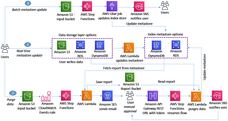
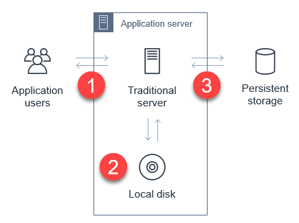
To address the challenge of implementing a data purge framework, we reduced the problem to the straightforward use case of deleting a user’s data from a platform that uses AWS for its data pipeline. The following diagram illustrates this use case.

We’re introducing the idea of building and maintaining an index metastore that keeps track of the location of each user’s records and allows us locate to them efficiently, reducing the search space.

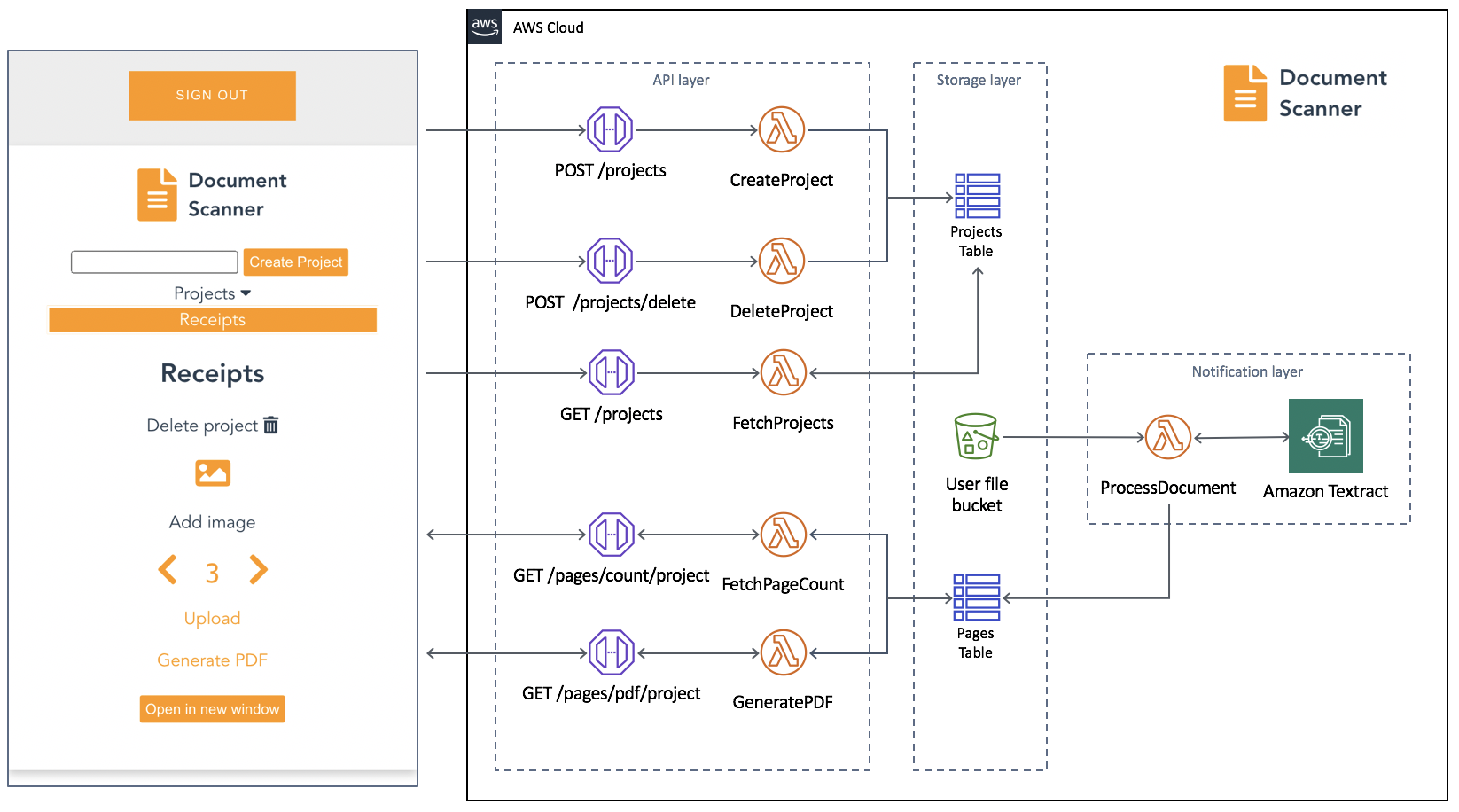
You can use the following architecture diagram to delete a specific user’s data within your organization’s AWS data lake.

For this initial version, we created three user flows that map each task to a fitting AWS service:

Flow 1: Real-time metastore update

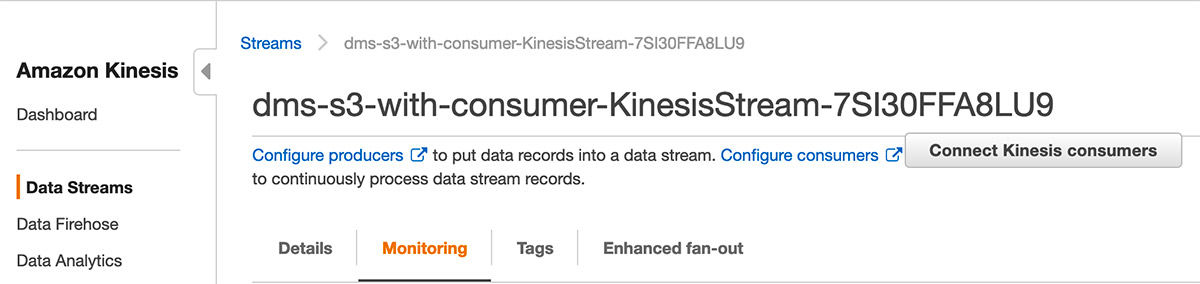
The S3 ObjectCreated or ObjectDelete events trigger an AWS Lambda function that parses the object and performs an add/update/delete operation to keep the metadata index up to date. You can implement a simple workflow for any other storage layer, such as Amazon Relational Database Service (RDS), Amazon Aurora, or Amazon Elasticsearch Service (ES). We use Amazon DynamoDB and Amazon RDS for PostgreSQL as the index metadata storage options, but our approach is flexible to any other technology.

Flow 2: Purge data

When a user asks for their data to be deleted, we trigger an AWS Step Functions state machine through Amazon CloudWatch to orchestrate the workflow. Its first step triggers a Lambda function that queries the metadata index to identify the storage layers that contain user records and generates a report that’s saved to an S3 report bucket. A Step Functions activity is created and picked up by a Lambda Node JS based worker that sends an email to the approver through Amazon Simple Email Service (SES) with approve and reject links.

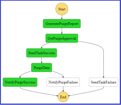
The following diagram shows a graphical representation of the Step Function state machine as seen on the AWS Management Console.

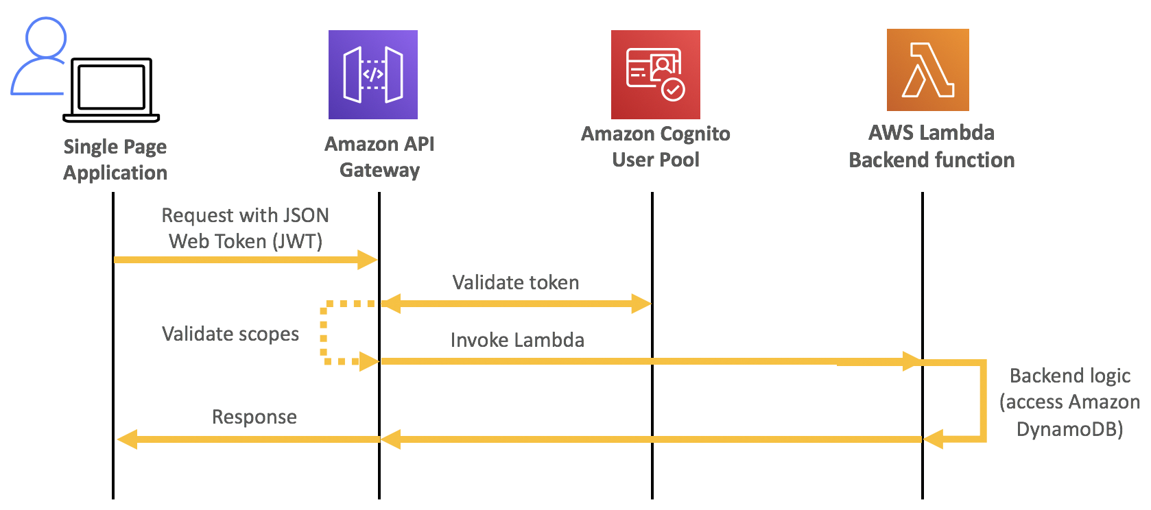
The approver selects one of the two links, which then calls an Amazon API Gateway endpoint that invokes Step Functions to resume the workflow. If you choose the approve link, Step Functions triggers a Lambda function that takes the report stored in the bucket as input, deletes the objects or records from the storage layer, and updates the index metastore. When the purging job is complete, Amazon Simple Notification Service (SNS) sends a success or fail email to the user.

The following diagram represents the Step Functions flow on the console if the purge flow completed successfully.

For the complete code base, see step-function-definition.json in the GitHub repo.

Flow 3: Batch metastore update

This flow refers to the use case of an existing data lake for which index metastore needs to be created. You can orchestrate the flow through AWS Step Functions, which takes historical data as input and updates metastore through a batch job. Our current implementation doesn’t include a sample script for this user flow.

Our framework

We now walk you through the two use cases we followed for our implementation:

  • You have multiple user records stored in each Amazon S3 file
  • A user has records stored in homogenous AWS storage layers

Within these two approaches, we demonstrate alternatives that you can use to store your index metastore.

Indexing by S3 URI and row number

For this use case, we use a free tier RDS Postgres instance to store our index. We created a simple table with the following code:

CREATE UNLOGGED TABLE IF NOT EXISTS user_objects (
				userid TEXT,
				s3path TEXT,
				recordline INTEGER
			);

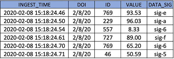
You can index on user_id to optimize query performance. On object upload, for each row, you need to insert into the user_objects table a row that indicates the user ID, the URI of the target Amazon S3 object, and the row that corresponds to the record. For instance, when uploading the following JSON input, enter the following code:

{"user_id":"V34qejxNsCbcgD8C0HVk-Q","body":"…"}
{"user_id":"ofKDkJKXSKZXu5xJNGiiBQ","body":"…"}
{"user_id":"UgMW8bLE0QMJDCkQ1Ax5Mg","body ":"…"}

We insert the tuples into user_objects in the Amazon S3 location s3://gdpr-demo/year=2018/month=2/day=26/input.json. See the following code:

(“V34qejxNsCbcgD8C0HVk-Q”, “s3://gdpr-demo/year=2018/month=2/day=26/input.json”, 0)
(“ofKDkJKXSKZXu5xJNGiiBQ”, “s3://gdpr-demo/year=2018/month=2/day=26/input.json”, 1)
(“UgMW8bLE0QMJDCkQ1Ax5Mg”, “s3://gdpr-demo/year=2018/month=2/day=26/input.json”, 2)

You can implement the index update operation by using a Lambda function triggered on any Amazon S3 ObjectCreated event.

When we get a delete request from a user, we need to query our index to get some information about where we have stored the data to delete. See the following code:

SELECT s3path,
                ARRAY_AGG(recordline)
                FROM user_objects
                WHERE userid = ‘V34qejxNsCbcgD8C0HVk-Q’
                GROUP BY;

The preceding example SQL query returns rows like the following:

(“s3://gdpr-review/year=2015/month=12/day=21/review-part-0.json“, {2102,529})

The output indicates that lines 529 and 2102 of S3 object s3://gdpr-review/year=2015/month=12/day=21/review-part-0.json contain the requested user’s data and need to be purged. We then need to download the object, remove those rows, and overwrite the object. For a Python implementation of the Lambda function that implements this functionality, see deleteUserRecords.py in the GitHub repo.

Having the record line available allows you to perform the deletion efficiently in byte format. For implementation simplicity, we purge the rows by replacing the deleted rows with an empty JSON object. You pay a slight storage overhead, but you don’t need to update subsequent row metadata in your index, which would be costly. To eliminate empty JSON objects, we can implement an offline vacuum and index update process.

Indexing by file name and grouping by index key

For this use case, we created a DynamoDB table to store our index. We chose DynamoDB because of its ease of use and scalability; you can use its on-demand pricing model so you don’t need to guess how many capacity units you might need. When files are uploaded to the data lake, a Lambda function parses the file name (for example, 1001-.csv) to identify the user identifier and populates the DynamoDB metadata table. Userid is the partition key, and each different storage layer has its own attribute. For example, if user 1001 had data in Amazon S3 and Amazon RDS, their records look like the following code:

{"userid:": 1001, "s3":{"s3://path1", "s3://path2"}, "RDS":{"db1.table1.column1"}}

For a sample Python implementation of this functionality, see update-dynamo-metadata.py in the GitHub repo.

On delete request, we query the metastore table, which is DynamoDB, and generate a purge report that contains details on what storage layers contain user records, and storage layer specifics that can speed up locating the records. We store the purge report to Amazon S3. For a sample Lambda function that implements this logic, see generate-purge-report.py in the GitHub repo.

After the purging is approved, we use the report as input to delete the required resources. For a sample Lambda function implementation, see gdpr-purge-data.py in the GitHub repo.

Implementation and technology alternatives

We explored and evaluated multiple implementation options, all of which present tradeoffs, such as implementation simplicity, efficiency, critical data compliance, and feature completeness:

  • Scan every record of the data file to create an index – Whenever a file is uploaded, we iterate through its records and generate tuples (userid, s3Uri, row_number) that are then inserted to our metadata storing layer. On delete request, we fetch the metadata records for requested user IDs, download the corresponding S3 objects, perform the delete in place, and re-upload the updated objects, overwriting the existing object. This is the most flexible approach because it supports a single object to store multiple users’ data, which is a very common practice. The flexibility comes at a cost because it requires downloading and re-uploading the object, which introduces a network bottleneck in delete operations. User activity datasets such as customer product reviews are a good fit for this approach, because it’s unexpected to have multiple records for the same user within each partition (such as a date partition), and it’s preferable to combine multiple users’ activity in a single file. It’s similar to what was described in the section “Indexing by S3 URI and row number” and sample code is available in the GitHub repo.
  • Store metadata as file name prefix – Adding the user ID as the prefix of the uploaded object under the different partitions that are defined based on query pattern enables you to reduce the required search operations on delete request. The metadata handling utility finds the user ID from the file name and maintains the index accordingly. This approach is efficient in locating the resources to purge but assumes a single user per object, and requires you to store user IDs within the filename, which might require InfoSec considerations. Clickstream data, where you would expect to have multiple click events for a single customer on a single date partition during a session, is a good fit. We covered this approach in the section “Indexing by file name and grouping by index key” and you can download the codebase from the GitHub repo.
  • Use a metadata file – Along with uploading a new object, we also upload a metadata file that’s picked up by an indexing utility to create and maintain the index up to date. On delete request, we query the index, which points us to the records to purge. A good fit for this approach is a use case that already involves uploading a metadata file whenever a new object is uploaded, such as uploading multimedia data, along with their metadata. Otherwise, uploading a metadata file on every object upload might introduce too much of an overhead.
  • Use the tagging feature of AWS services – Whenever a new file is uploaded to Amazon S3, we use the Put Object Tagging Amazon S3 operation to add a key-value pair for the user identifier. Whenever there is a user data delete request, it fetches objects with that tag and deletes them. This option is straightforward to implement using the existing Amazon S3 API and can therefore be a very initial version of your implementation. However, it involves significant limitations. It assumes a 1:1 cardinality between Amazon S3 objects and users (each object only contains data for a single user), searching objects based on a tag is limited and inefficient, and storing user identifiers as tags might not be compliant with your organization’s InfoSec policy.
  • Use Apache Hudi – Apache Hudi is becoming a very popular option to perform record-level data deletion on Amazon S3. Its current version is restricted to Amazon EMR, and you can use it if you start to build your data lake from scratch, because you need to store your as Hudi datasets. Hudi is a very active project and additional features and integrations with more AWS services are expected.

The key implementation decision of our approach is separating the storage layer we use for our data and the one we use for our metadata. As a result, our design is versatile and can be plugged in any existing data pipeline. Similar to deciding what storage layer to use for your data, there are many factors to consider when deciding how to store your index:

  • Concurrency of requests – If you don’t expect too many simultaneous inserts, even something as simple as Amazon S3 could be a starting point for your index. However, if you get multiple concurrent writes for multiple users, you need to look into a service that copes better with transactions.
  • Existing team knowledge and infrastructure – In this post, we demonstrated using DynamoDB and RDS Postgres for storing and querying the metadata index. If your team has no experience with either of those but are comfortable with Amazon ES, Amazon DocumentDB (with MongoDB compatibility), or any other storage layer, use those. Furthermore, if you’re already running (and paying for) a MySQL database that’s not used to capacity, you could use that for your index for no additional cost.
  • Size of index – The volume of your metadata is orders of magnitude lower than your actual data. However, if your dataset grows significantly, you might need to consider going for a scalable, distributed storage solution rather than, for instance, a relational database management system.

Conclusion

GDPR has transformed best practices and introduced several extra technical challenges in designing and implementing a data lake. The reference architecture and scripts in this post may help you delete data in a manner that’s compliant with GDPR.

Let us know your feedback in the comments and how you implemented this solution in your organization, so that others can learn from it.


About the Authors

George Komninos is a Data Lab Solutions Architect at AWS. He helps customers convert their ideas to a production-ready data product. Before AWS, he spent 3 years at Alexa Information domain as a data engineer. Outside of work, George is a football fan and supports the greatest team in the world, Olympiacos Piraeus.


Sakti Mishra is a Data Lab Solutions Architect at AWS. He helps customers architect data analytics solutions, which gives them an accelerated path towards modernization initiatives. Outside of work, Sakti enjoys learning new technologies, watching movies, and travel.

Streaming data from Amazon S3 to Amazon Kinesis Data Streams using AWS DMS

Post Syndicated from Mahesh Goyal original https://aws.amazon.com/blogs/big-data/streaming-data-from-amazon-s3-to-amazon-kinesis-data-streams-using-aws-dms/

Stream processing is very useful in use cases where we need to detect a problem quickly and improve the outcome based on data, for example production line monitoring or supply chain optimizations.

This blog post walks you through process of streaming existing data files and ongoing changes from Amazon Simple Storage Service (Amazon S3) to Amazon Kinesis. You achieve this by using AWS Database Migration Service (AWS DMS). AWS DMS enables you to seamlessly migrate data from supported sources to relational databases, data warehouses, streaming platforms, and other data stores in AWS cloud.

Many SaaS, third-party applications already integrate with Amazon S3 and can deliver records to S3 buckets. In certain use cases, you need to further process this data in near-real-time to generate alerts. Use cases like threat detection and application monitoring require generating insights in seconds. Waiting for batch processes often leads to a delay in data analysis and reduces the ability of systems to respond quickly to critical situations. For such use cases, you need a way to convert batch to stream processing by expanding the existing integrations of your applications with Amazon S3.

You can use AWS DMS for such data-processing requirements. AWS DMS lets to expand your existing application into Amazon S3 to produce data in Amazon Kinesis Data Streams for real-time analytics without writing and maintaining new code. AWS DMS supports specifying Amazon S3 as the source and streaming services like Kinesis and Amazon Managed Streaming of Kafka (Amazon MSK) as the target. AWS DMS allows migration of full and change data capture (CDC) files to these services. AWS DMS performs this task out of box without any complex configuration or code development. You can also configure an AWS DMS replication instance to scale up or down depending on the workload.

For this post, we focus on streaming data to Kinesis. We deploy an AWS CloudFormation template to get started in minutes and explore the streaming pipeline.

Architecture overview

Third-party applications such as web, API, and data-integration services produce data and log files in S3 buckets. Data lakes built on AWS process and store data in Amazon S3 at different stages. AWS DMS supports Amazon S3 as the source and Kinesis as the target, so data stored in an S3 bucket is streamed to Kinesis. Several consumers, such as AWS Lambda, Amazon Kinesis Data Firehose, Amazon Kinesis Data Analytics, and the Kinesis Consumer Library (KCL), can consume the data concurrently to perform real-time analytics on the dataset. Each AWS service in this architecture can scale independently as needed.

The following diagram shows the architecture of this solution.

Deploying AWS CloudFormation

To get started, you first deploy the CloudFormation template to create the core components of the architecture. AWS CloudFormation automates the deployment of technology and infrastructure in a safe and repeatable manner across multiple Regions and accounts with the least amount of effort and time. To create these resources, complete the following steps:

  1. Sign in to the AWS Management Console and choose the us-west-2 Region.
  2. Choose Launch Stack:
  3. Choose Next.

 This automatically launches AWS CloudFormation in your AWS account with a template. It prompts you to sign in as needed. You can view the CloudFormation template on the console.

  1. For Stack name, enter a stack name.
  2. On the next screen, choose your VPC and subnet IDs.
  3. For Does DMS VPC and Cloudwatch role Exists?, enter Y if the managed AWS Identity and Access Management (IAM) roles dms-vpc-role and dms-cloudwatch-logs-role exist in your account. Otherwise, leave at the default N.

If you want to deploy the AWS DMS endpoint in a private subnet, enable the VPC endpoints for Kinesis and Amazon S3 before deploying the template.

  1. Choose Next.
  2. Acknowledge resource creation under Capabilities on the final screen and choose Create.

The stack takes 5–10 minutes to complete, during which it performs the following:

  • Creates a source S3 bucket and target Kinesis data stream with two shards.
  • Creates an AWS DMS replication instance, Amazon S3 source endpoint, and Kinesis target.
  • Maps the S3 bucket and data steam to their respective endpoints.
  • Configures a replication task with the required parameters.
  • Creates an AWS Lambda function with a trigger to consume records from Kinesis. For more information, see Using AWS Lambda with Amazon Kinesis.

The files required for this demo don’t come with the template. Download blog_sample_file.zip and upload it to the source bucket before starting the AWS DMS task.

Using Amazon S3 as the source

When you use Amazon S3 as the source, the data files (full load and CDC) must be in comma-separated value (CSV) format.

In addition to the data files, AWS DMS also requires an external table definition. An external table definition is a JSON document that describes how AWS DMS should interpret the data from Amazon S3.

Amazon S3 file paths for full load and CDC files are required for AWS DMS to run the task. Make sure that files names are sequentially numbered to replicate the data in the correct order. In addition, AWS DMS allows you to specify the column delimiter, row delimiter, and other parameters using extra connection attributes.

AWS DMS can identify the operation to perform for each load record in two ways: from the record’s keyword value INSERT or I.

For more information, see Using Amazon S3 as a source for AWS DMS.

Using Amazon Kinesis as the target

AWS publishes records to a Kinesis data stream as JSON. During conversion, AWS DMS serializes each record from the source Amazon S3 files into an attribute-value pair in JSON format.

AWS DMS publishes each record in the source Amazon S3 file as one JSON data record in a data stream regardless of the action specified in the source file.

Additionally, AWS DMS allows object mapping to migrate data from source files to a data stream. Object mapping determines the structure of data records in the stream.

AWS DMS also supports multi-threaded migration for full load and CDC with task settings. You can promote the performance by setting multiple threads, buffer size, and parallel queue.

For more information, see Using Amazon Kinesis Data Streams as a target for AWS Database Migration Service.

Walkthrough

The AWS CloudFormation deployment takes care of all the infrastructure. Now you need files to complete this use case.

  1. Download blog_sample_file.zip, which contains full and CDC load files in CSV format.

If your source files aren’t in CSV, convert the file format to CSV. One conversion method is by using AWS Glue. For more information, see Format Options for ETL Inputs and Outputs in AWS Glue.

The following screenshot shows the sample records of the full load files that you use for this use case.

CDC files require additional attributes for AWS DMS to identify the action, table, and schema.

  1. Reformat the files as follows:
  • Operation – The change operation to be performed: INSERT or I, UPDATE or U, or DELETE or D.
  • Table name – The name of the source table.
  • Schema name – The name of the source schema.
  • Data – One or more columns that represent the data to be changed.

The following screenshot shows sample records of the CDC file.

External table definition is required in the source endpoint configuration. For this post, the definition is embedded in AWS CloudFormation.

  1. Enter the following code for the table definition for the full and CDC files:
    {
    	“TableCount”: “1",
    	“Tables”: [{
    		“TableName”: “table01”,
    		“TablePath”: “schema01/table01/“,
    		“TableOwner”: “schema01",
    		“TableColumns”: [{
    			“ColumnName”: “ingest_time”,
    			“ColumnType”: “TIMESTAMP”,
    			“ColumnNullable”: “false”,
    			“ColumnIsPk”: “true”
    		}, {
    			“ColumnName”: “doi”,
    			“ColumnType”: “STRING”,
    			“ColumnLength”: “30”
    		}, {
    			“ColumnName”: “id”,
    			“ColumnType”: “INT8”
    		}, {
    			“ColumnName”: “value”,
    			“ColumnType”: “NUMERIC”,
    			“ColumnPrecision”: “5”,
    			“ColumnScale”: “2”
    		}, {
    			“ColumnName”: “data_sig”,
    			“ColumnType”: “STRING”,
    			“ColumnLength”: “10”
    		}],
    		“TableColumnsTotal”: “5”
    	}]
    }
    

  2. Create folder structures under the source S3 bucket created through the CloudFormation template.
    1. Create folders schema01/table01/ for full load and cdcfile/ for CDC data files.
    2. Also, file names should be in incremental, as listed in the following CLI output.
      $aws s3 ls s3://blog-xxxxxxxx/schema01/table01 --recursive --human-readable --summarize
      2020-08-03 22:05:57    5.0 MiB schema01/table01/full_000
      2020-08-03 22:05:51    5.0 MiB schema01/table01/full_001
      2020-08-03 22:06:00    5.0 MiB schema01/table01/full_002
      2020-08-03 22:05:56    5.0 MiB schema01/table01/full_003
      2020-08-03 22:05:59    3.1 MiB schema01/table01/full_004
      
      $aws s3 ls s3://blog-xxxxxxxx/cdcfile --recursive --human-readable --summarize
      2020-08-03 22:06:28    4.8 MiB cdc/cdc_000
      2020-08-03 22:06:28    4.8 MiB cdc/cdc_001
      2020-08-03 22:06:26    4.8 MiB cdc/cdc_002
      2020-08-03 22:06:19    4.8 MiB cdc/cdc_003
      

  3. After the files are copied, on the AWS DMS console, choose Replication.
  4. Validate the instance status and configuration.
  5. Choose Endpoints.
  6. Validate the status and configuration of the Amazon S3 source endpoint and make sure that the connection to the replication instance is successful.
  7. Similarly, validate the status and configuration of Kinesis target endpoint and make sure that the connection to the replication instance is successful.
  8. Choose Database migration task.
  9. Verify that the source and target are mapped correctly.
  10. After validating all the configurations, restart the AWS DMS task. Because the task has been created and never started, choose Restart/Resume to start full load and CDC.

After data migration starts, you can see it listed under Table statistics. For more information, see How do I use table statistics to monitor an AWS DMS task?

AWS DMS completes the full load first and migrates change data as files are uploaded to the bucket location specified in the cdcPath parameter.

  1. While the migration is in progress, on the Kinesis console, check the IncomingBytes metrics on the Monitoring tab to confirm the data is streaming to Kinesis Data Streams.
  2. To confirm that the data streamed is being consumed by the Lambda consumer, use the GetRecords.Bytes metric.

You’re now ready to validate the records in Lambda. Lambda is configured to read from Kinesis through a trigger.

The Lambda consumer for this post is a sample function that consumes the records from the Kinesis data stream, decodes the base64 encoded data, and prints the records to the Amazon CloudWatch log group.

  1. On the Monitoring tab, open the recent logstream under CloudWatch Log Insights to see the printed records.

For more information about monitoring, see Monitoring functions in the AWS Lambda console.

You can add processing logic to the Lambda function as per your requirements to aggregate or process the records. You can also configure a Lambda destination for further processing. Lambda asynchronous invocations can put an event or message on Amazon Simple Notification Service (Amazon SNS), Amazon Simple Queue Service (Amazon SQS), or Amazon EventBridge. For more information, see Introducing AWS Lambda Destinations.

Best practice considerations

When implementing this solution, consider the following best practices:

  • Full load allows to you stream existing data from an S3 bucket to Kinesis. You can use full load to migrate previously stored data before streaming CDC data. The full load data should already exist before the task starts. For new CDC files, the data is streamed to Kinesis on a file delivery event in real-time.
  • For loading multiple tables, you can specify the table count and table properties in an external table definition file. The CDC path remains the same and AWS DMS maps the records to tables based on the metadata fields.
  • During a heavy workload, the AWS DMS instance can be constrained to resources like CPU, memory, storage, and I/O. For optimal transfer speed, monitor the CloudWatch metrics and scale the replication instance.
  • For migrating a large number of tables, you can speed up the transfer by setting the multi-threading parameter to higher values.
  • The CloudFormation template creates a data stream with two shards. As the data flow rate to the stream increases, you can scale the number of shards in the stream to adapt to changes. Monitoring Kinesis with CloudWatch metrics for IncomingRecords and WriteProvisionedThroughputExceeded provides insights on how to scale the shards.
  • Object mapping in the AWS DMS task defines the partition key. This partition key is used to group data by shard within a stream. The default partition key AWS DMS uses is TableName. You can use attribute mapping to change the partition key to a value of one of the fields in the JSON, or the primary key of the table in the source database. You can also set the partition key to a constant value to stream all the data to a single shard in the stream.
  • By default, Lambda invokes the function as soon as records are available in the stream. To avoid invoking the function with a small number of records, configure the event source to buffer records for up to 5 minutes by configuring a batch window. For more information, see Using AWS Lambda with Amazon Kinesis.
  • When Kinesis is configured as a trigger for Lambda, you can increase the concurrency to process multiple batches from each shard in parallel. Lambda can process up to 10 batches in each shard simultaneously. For more information about concurrency, see New AWS Lambda scaling controls for Kinesis and DynamoDB event sources.

Cleaning up

After successful testing and validation, you should delete all the resources deployed through the CloudFormation template to avoid any unwanted costs. First empty the S3 bucket and stop the AWS DMS task. Then delete the appropriate stacks on the AWS CloudFormation console.

Summary

This post describes a solution for converting batch processing to near real-time using AWS DMS. This solution greatly simplifies the process of migrating records from Amazon S3 to Kinesis for analysis. Kinesis as an AWS DMS target allows multiple systems to consume data simultaneously. Having a near-steaming pipeline allows you to make sense of all the changes in near-real time, which ultimately expands your organization’s ability for better decision-making. All the resources used in this solution scale seamlessly and allow you to focus on analysis, alerting, reporting, and fraud detection instead of focusing on platform setup and maintenance. This promotes cost-effectiveness while reducing operational burden.


About the Author

Mahesh Goyal is a Data Architect in Big Data at AWS. He works with customers in their journey to the cloud with a focus on big data and data warehouses. In his spare time, Mahesh likes to listen to music and explore new food places with his family.


Charishma Makineni is a Technical Account Manager at AWS. She works with enterprise customers to help them build secure and scalable solutions on the AWS cloud. She is focused on Big data and Analytics technologies. Outside of work, Charishma enjoys being outdoors, gardening and experimenting with cooking.


Suresh Patnam is a Solutions Architect at AWS. He helps customers innovate on the AWS platform by building highly available, scalable, and secure architectures on Big Data and AI/ML. In his spare time, Suresh enjoys playing tennis and spending time with his family.

Analyzing Amazon S3 server access logs using Amazon ES

Post Syndicated from Mahesh Goyal original https://aws.amazon.com/blogs/big-data/analyzing-amazon-s3-server-access-logs-using-amazon-es/

When you use Amazon Simple Storage Service (Amazon S3) to store corporate data and host websites, you need additional logging to monitor access to your data and the performance of your application. An effective logging solution enhances security and improves the detection of security incidents. With the advent of increased data storage needs, you can rely on Amazon S3 for a range of use cases and simultaneously looking for ways to analyze your logs to ensure compliance, perform the audit, and discover risks.

Amazon S3 lets you monitor the traffic using the server access logging feature. With server access logging, you can capture and monitor the traffic to your S3 bucket at any time, with detailed information about the source of the request. The logs are stored in the S3 bucket you own in the same Region. This addresses the security and compliance requirements of most organizations. The logs are critical for establishing baselines, analyzing access patterns, and identifying trends. For example, the logs could answer a financial organization’s question about how many requests are made to a bucket and who is making what type of access requests to the objects.

You can discover insights from server access logs through several different methods. One common option is by using Amazon Athena or Amazon Redshift Spectrum and query the log files stored in Amazon S3. However, this solution poses high latency with an exponential growth in volume. It requires further integration with Amazon QuickSight to add visualization capabilities.

You can address this by using Amazon Elasticsearch Service (Amazon ES). Amazon ES is a managed service that makes it easier to deploy, operate, and scale Elasticsearch clusters in the AWS Cloud. Elasticsearch is a popular open-source search and analytics engine for use cases such as log analytics, real-time application monitoring, and clickstream analysis. The service provides support for open-source Elasticsearch APIs, managed Kibana, and integration with other AWS services such as Amazon S3 and Amazon Kinesis for loading streaming data into Amazon ES.

This post walks you through automating ingestion of server access logs from Amazon S3 into Amazon ES using AWS Lambda and visualizing the data in Kibana.

Architecture overview

Server access logging is enabled on source buckets, and logs are delivered to access log bucket. The access log bucket is configured to send an event to the Lambda function when a log file is created. On an event trigger, the Lambda function reads the file, processes the access log, and sends it to Amazon ES. When the logs are available, you can use Kibana to create interactive visuals and analyze the logs over a time period.

When designing a log analytics solution for high-frequency incoming data, you should consider buffering layers to avoid instability in the system. Buffering helps you streamline processes for unpredictable incoming log data. For such use cases, you can take advantage of managed services like Amazon Kinesis Data Streams, Amazon Kinesis Data Firehose, and Amazon Managed Streaming for Apache Kafka (Amazon MSK).

Streaming services buffer data before delivering it to Amazon ES. This helps you avoid overwhelming your cluster with spiky ingestion events. Kinesis Data Firehose can reliably load data into Amazon ES. Kinesis Data Firehose lets you choose a buffer size of 1–100 MiBs and a buffer interval of 60–900 seconds when Amazon ES is selected as the destination. Kinesis Data Firehose also scales automatically to match the throughput of your data and requires no ongoing administration. For more information, see Ingest streaming data into Amazon Elasticsearch Service within the privacy of your VPC with Amazon Kinesis Data Firehose.

The following diagram illustrates the solution architecture.

Prerequisites

Before creating resources in AWS CloudFormation, you must enable server access logging on the source bucket. Open the S3 bucket properties and look for Amazon S3 access and delivery bucket. See the following screenshot.

You also need an AWS Identity and Access Management (IAM) user with sufficient permissions to interact with the AWS Management Console and related AWS services. The user must have access to create IAM roles and policies via the CloudFormation template.

Setting up the resources with AWS CloudFormation

First, deploy the CloudFormation template to create the core components of the architecture. AWS CloudFormation automates the deployment of technology and infrastructure in a safe and repeatable manner across multiple Regions and multiple accounts with the least amount of effort and time.

  1. Sign in to the console and choose the Region of the bucket storing the access log. For this post, I use us-east-1.
  2. Launch the stack:
  3. Choose Next.
  4. For Stack name, enter a name.
  5. On the Parameters page, enter the following parameters:
    1. VPC Configuration – Select any VPC that has at least two private subnets. The template deploys the Amazon ES service domain and Lambda within the VPC.
    2. Private subnets – Select two private subnets of the VPC. The route tables associated with subnets must have a NAT gateway configuration and VPC endpoint for Amazon S3 to privately connect the bucket from Lambda.
    3. Access log S3 bucket – Enter the S3 bucket where access logs are delivered. The template configures event notification on the bucket to trigger the Lambda function.
    4. Amazon ES domain name – Specify the Amazon ES domain name to be deployed through the template.
  6. Choose Next.
  7. On the next page, choose Next.
  8. Acknowledge resource creation under Capabilities and transforms and choose Create.

The stack takes about 10–15 minutes to complete. The CloudFormation stack does the following:

  • Creates an Amazon ES domain with fine-grained access control enabled on it. Fine-grained access control is configured with a primary user in the internal user database.
  • Creates IAM role for the Lambda function with required permission to read from S3 bucket and write to Amazon ES.
  • Creates Lambda within the same VPC of Amazon ES elastic network interfaces (ENI). Amazon ES places an ENI in the VPC for each of your data nodes. The communication from Lambda to the Amazon ES domain is via this ENI.
  • Configures file create event notification on Access log S3 bucket to trigger the Lambda function. The function code segments are discussed in detail in this GitHub project.

You must make several considerations before you proceed with a production-grade deployment. For this post, I use one primary shard with no replicas. As a best practice, we recommend deploying your domain into three Availability Zones with at least two replicas. This configuration lets Amazon ES distribute replica shards to different Availability Zones than their corresponding primary shards and improves the availability of your domain. For more information about sizing your Amazon ES, see Get started with Amazon Elasticsearch Service: T-shirt-size your domain.

We recommend setting the shard count based on your estimated index size, using 50 GB as a maximum target shard size. You should also define an index template to set the primary and replica shard counts before index creation. For more information about best practices, see Best practices for configuring your Amazon Elasticsearch Service domain.

For high-frequency incoming data, you can rotate indexes either per day or per week depending on the size of data being generated. You can use Index State Management to define custom management policies to automate routine tasks and apply them to indexes and index patterns.

Creating the Kibana user

With Amazon ES, you can configure fine-grained users to control access to your data. Fine-grained access control adds multiple capabilities to give you tighter control over your data. This feature includes the ability to use roles to define granular permissions for indexes, documents, or fields and to extend Kibana with read-only views and secure multi-tenant support. For more information on granular access control, see Fine-Grained Access Control in Amazon Elasticsearch Service.

For this post, you create a fine-grained role for Kibana access and map it to a user.

  1. Navigate to Kibana and enter the primary user credentials:
    1. User nameadminuser01
    2. PasswordStrongP@ssw0rd

To access Kibana, you must have access to the VPC. For more information about accessing Kibana, see Controlling Access to Kibana.

  1. Choose Security, Roles.
  2. For Role name, enter kibana_only_role.
  3. For Cluster-wide permissions, choose cluster_composite_ops_ro.
  4. For Index patterns, enter access-log and kibana.
  5. For Permissions: Action Groups, choose read, delete, index, and manage.
  6. Choose Save Role Definition.
  7. Choose Security, Internal User Database, and Create a New User.
  8. For Open Distro Security Roles, choose Kibana_only_role (created earlier).
  9. Choose Submit.

The user kibanauser01 now has full access to Kibana and access-logs indexes. You can log in to Kibana with this user and create the visuals and dashboards.

Building dashboards

You can use Kibana to build interactive visuals and analyze the trends and combine the visuals for different use cases in a dashboard. For example, you may want to see the number of requests made to the buckets in the last two days.

  1. Log in to Kibana using kibanauser01.
  2. Create an index pattern and set the time range
  3. On the Visualize section of your Kibana dashboard, add a new visualization.
  4. Choose Vertical Bar.

You can select any time range and visual based on your requirements.

  1. Choose the index pattern and then configure your graph options.
  2. In the Metrics pane, expand Y-Axis.
  3. For Aggregation, choose Count.
  4. For Custom Label, enter Request Count.
  5. Expand the X-Axis
  6. For Aggregation, choose Terms.
  7. For Field, choose bucket.
  8. For Order By, choose metric: Request Count.
  9. Choose Apply changes.
  10. Choose Add sub-bucket and expand the Split Series
  11. For Sub Aggregation, choose Date Histogram.
  12. For Field, choose requestdatetime.
  13. For Interval, choose Daily.
  14. Apply the changes by choosing the play icon at the top of the page.

You should see the visual on the right side, similar to the following screenshot.

You can combine graphs of different use cases into a dashboard. I have built some example graphs for general use cases like the number of operations per bucket, user action breakdown for buckets, HTTPS status rate, top users, and tabular formatted error details. See the following screenshots.

Cleaning up

Delete all the resources deployed through the CloudFormation template to avoid any unintended costs.

  1. Disable the access log on source bucket.
  2. On to the CloudFormation console, identify the stacks appropriately, and delete

Summary

This post detailed a solution to visualize and monitor Amazon S3 access logs using Amazon ES to ensure compliance, perform security audits, and discover risks and patterns at scale with minimal latency. To learn about best practices of Amazon ES, see Amazon Elasticsearch Service Best Practices. To learn how to analyze and create a dashboard of data stored in Amazon ES, see the AWS Security Blog.


About the Authors

Mahesh Goyal is a Data Architect in Big Data at AWS. He works with customers in their journey to the cloud with a focus on big data and data warehouses. In his spare time, Mahesh likes to listen to music and explore new food places with his family.


Uploading to Amazon S3 directly from a web or mobile application

Post Syndicated from James Beswick original https://aws.amazon.com/blogs/compute/uploading-to-amazon-s3-directly-from-a-web-or-mobile-application/

In web and mobile applications, it’s common to provide users with the ability to upload data. Your application may allow users to upload PDFs and documents, or media such as photos or videos. Every modern web server technology has mechanisms to allow this functionality. Typically, in the server-based environment, the process follows this flow:

Application server upload process

  1. The user uploads the file to the application server.
  2. The application server saves the upload to a temporary space for processing.
  3. The application transfers the file to a database, file server, or object store for persistent storage.

While the process is simple, it can have significant side-effects on the performance of the web-server in busier applications. Media uploads are typically large, so transferring these can represent a large share of network I/O and server CPU time. You must also manage the state of the transfer to ensure that the entire object is successfully uploaded, and manage retries and errors.

This is challenging for applications with spiky traffic patterns. For example, in a web application that specializes in sending holiday greetings, it may experience most traffic only around holidays. If thousands of users attempt to upload media around the same time, this requires you to scale out the application server and ensure that there is sufficient network bandwidth available.

By directly uploading these files to Amazon S3, you can avoid proxying these requests through your application server. This can significantly reduce network traffic and server CPU usage, and enable your application server to handle other requests during busy periods. S3 also is highly available and durable, making it an ideal persistent store for user uploads.

In this blog post, I walk through how to implement serverless uploads and show the benefits of this approach. This pattern is used in the Happy Path web application. You can download the code from this blog post in this GitHub repo.

Overview of serverless uploading to S3

When you upload directly to an S3 bucket, you must first request a signed URL from the Amazon S3 service. You can then upload directly using the signed URL. This is two-step process for your application front end:

Serverless uploading to S3

  1. Call an Amazon API Gateway endpoint, which invokes the getSignedURL Lambda function. This gets a signed URL from the S3 bucket.
  2. Directly upload the file from the application to the S3 bucket.

To deploy the S3 uploader example in your AWS account:

  1. Navigate to the S3 uploader repo and install the prerequisites listed in the README.md.
  2. In a terminal window, run:
    git clone https://github.com/aws-samples/amazon-s3-presigned-urls-aws-sam
    cd amazon-s3-presigned-urls-aws-sam
    sam deploy --guided
  3. At the prompts, enter s3uploader for Stack Name and select your preferred Region. Once the deployment is complete, note the APIendpoint output.

CloudFormation stack outputs

Testing the application

I show two ways to test this application. The first is with Postman, which allows you to directly call the API and upload a binary file with the signed URL. The second is with a basic frontend application that demonstrates how to integrate the API.

To test using Postman:

  1. First, copy the API endpoint from the output of the deployment.
  2. In the Postman interface, paste the API endpoint into the box labeled Enter request URL.
  3. Choose Send.Postman test
  4. After the request is complete, the Body section shows a JSON response. The uploadURL attribute contains the signed URL. Copy this attribute to the clipboard.
  5. Select the + icon next to the tabs to create a new request.
  6. Using the dropdown, change the method from GET to PUT. Paste the URL into the Enter request URL box.
  7. Choose the Body tab, then the binary radio button.Select the binary radio button in Postman
  8. Choose Select file and choose a JPG file to upload.
    Choose Send. You see a 200 OK response after the file is uploaded.200 response code in Postman
  9. Navigate to the S3 console, and open the S3 bucket created by the deployment. In the bucket, you see the JPG file uploaded via Postman.Uploaded object in S3 bucket

To test with the sample frontend application:

  1. Copy index.html from the example’s repo to an S3 bucket.
  2. Update the object’s permissions to make it publicly readable.
  3. In a browser, navigate to the public URL of index.html file.Frontend testing app at index.html
  4. Select Choose file and then select a JPG file to upload in the file picker. Choose Upload image. When the upload completes, a confirmation message is displayed.Upload in the test app
  5. Navigate to the S3 console, and open the S3 bucket created by the deployment. In the bucket, you see the second JPG file you uploaded from the browser.Second uploaded file in S3 bucket

Understanding the S3 uploading process

When uploading objects to S3 from a web application, you must configure S3 for Cross-Origin Resource Sharing (CORS). CORS rules are defined as an XML document on the bucket. Using AWS SAM, you can configure CORS as part of the resource definition in the AWS SAM template:

   S3UploadBucket:
    Type: AWS::S3::Bucket
    Properties:
      CorsConfiguration:
        CorsRules:
        - AllowedHeaders:
            - "*"
          AllowedMethods:
            - GET
            - PUT
            - HEAD
          AllowedOrigins:
            - "*"

The preceding policy allows all headers and origins – it’s recommended that you use a more restrictive policy for production workloads.

In the first step of the process, the API endpoint invokes the Lambda function to make the signed URL request. The Lambda function contains the following code:

const AWS = require('aws-sdk')
AWS.config.update({ region: process.env.AWS_REGION })
const s3 = new AWS.S3()
const URL_EXPIRATION_SECONDS = 300

// Main Lambda entry point
exports.handler = async (event) => {
  return await getUploadURL(event)
}

const getUploadURL = async function(event) {
  const randomID = parseInt(Math.random() * 10000000)
  const Key = `${randomID}.jpg`

  // Get signed URL from S3
  const s3Params = {
    Bucket: process.env.UploadBucket,
    Key,
    Expires: URL_EXPIRATION_SECONDS,
    ContentType: 'image/jpeg'
  }
  const uploadURL = await s3.getSignedUrlPromise('putObject', s3Params)
  return JSON.stringify({
    uploadURL: uploadURL,
    Key
  })
}

This function determines the name, or key, of the uploaded object, using a random number. The s3Params object defines the accepted content type and also specifies the expiration of the key. In this case, the key is valid for 300 seconds. The signed URL is returned as part of a JSON object including the key for the calling application.

The signed URL contains a security token with permissions to upload this single object to this bucket. To successfully generate this token, the code calling getSignedUrlPromise must have s3:putObject permissions for the bucket. This Lambda function is granted the S3WritePolicy policy to the bucket by the AWS SAM template.

The uploaded object must match the same file name and content type as defined in the parameters. An object matching the parameters may be uploaded multiple times, providing that the upload process starts before the token expires. The default expiration is 15 minutes but you may want to specify shorter expirations depending upon your use case.

Once the frontend application receives the API endpoint response, it has the signed URL. The frontend application then uses the PUT method to upload binary data directly to the signed URL:

let blobData = new Blob([new Uint8Array(array)], {type: 'image/jpeg'})
const result = await fetch(signedURL, {
  method: 'PUT',
  body: blobData
})

At this point, the caller application is interacting directly with the S3 service and not with your API endpoint or Lambda function. S3 returns a 200 HTML status code once the upload is complete.

For applications expecting a large number of user uploads, this provides a simple way to offload a large amount of network traffic to S3, away from your backend infrastructure.

Adding authentication to the upload process

The current API endpoint is open, available to any service on the internet. This means that anyone can upload a JPG file once they receive the signed URL. In most production systems, developers want to use authentication to control who has access to the API, and who can upload files to your S3 buckets.

You can restrict access to this API by using an authorizer. This sample uses HTTP APIs, which support JWT authorizers. This allows you to control access to the API via an identity provider, which could be a service such as Amazon Cognito or Auth0.

The Happy Path application only allows signed-in users to upload files, using Auth0 as the identity provider. The sample repo contains a second AWS SAM template, templateWithAuth.yaml, which shows how you can add an authorizer to the API:

  MyApi:
    Type: AWS::Serverless::HttpApi
    Properties:
      Auth:
        Authorizers:
          MyAuthorizer:
            JwtConfiguration:
              issuer: !Ref Auth0issuer
              audience:
                - https://auth0-jwt-authorizer
            IdentitySource: "$request.header.Authorization"
        DefaultAuthorizer: MyAuthorizer

Both the issuer and audience attributes are provided by the Auth0 configuration. By specifying this authorizer as the default authorizer, it is used automatically for all routes using this API. Read part 1 of the Ask Around Me series to learn more about configuring Auth0 and authorizers with HTTP APIs.

After authentication is added, the calling web application provides a JWT token in the headers of the request:

const response = await axios.get(API_ENDPOINT_URL, {
  headers: {
    Authorization: `Bearer ${token}`
        }
})

API Gateway evaluates this token before invoking the getUploadURL Lambda function. This ensures that only authenticated users can upload objects to the S3 bucket.

Modifying ACLs and creating publicly readable objects

In the current implementation, the uploaded object is not publicly accessible. To make an uploaded object publicly readable, you must set its access control list (ACL). There are preconfigured ACLs available in S3, including a public-read option, which makes an object readable by anyone on the internet. Set the appropriate ACL in the params object before calling s3.getSignedUrl:

const s3Params = {
  Bucket: process.env.UploadBucket,
  Key,
  Expires: URL_EXPIRATION_SECONDS,
  ContentType: 'image/jpeg',
  ACL: 'public-read'
}

Since the Lambda function must have the appropriate bucket permissions to sign the request, you must also ensure that the function has PutObjectAcl permission. In AWS SAM, you can add the permission to the Lambda function with this policy:

        - Statement:
          - Effect: Allow
            Resource: !Sub 'arn:aws:s3:::${S3UploadBucket}/'
            Action:
              - s3:putObjectAcl

Conclusion

Many web and mobile applications allow users to upload data, including large media files like images and videos. In a traditional server-based application, this can create heavy load on the application server, and also use a considerable amount of network bandwidth.

By enabling users to upload files to Amazon S3, this serverless pattern moves the network load away from your service. This can make your application much more scalable, and capable of handling spiky traffic.

This blog post walks through a sample application repo and explains the process for retrieving a signed URL from S3. It explains how to the test the URLs in both Postman and in a web application. Finally, I explain how to add authentication and make uploaded objects publicly accessible.

To learn more, see this video walkthrough that shows how to upload directly to S3 from a frontend web application. For more serverless learning resources, visit https://serverlessland.com.

Building a serverless document scanner using Amazon Textract and AWS Amplify

Post Syndicated from Moheeb Zara original https://aws.amazon.com/blogs/compute/building-a-serverless-document-scanner-using-amazon-textract-and-aws-amplify/

This guide demonstrates creating and deploying a production ready document scanning application. It allows users to manage projects, upload images, and generate a PDF from detected text. The sample can be used as a template for building expense tracking applications, handling forms and legal documents, or for digitizing books and notes.

The frontend application is written in Vue.js and uses the Amplify Framework. The backend is built using AWS serverless technologies and consists of an Amazon API Gateway REST API that invokes AWS Lambda functions. Amazon Textract is used to analyze text from uploaded images to an Amazon S3 bucket. Detected text is stored in Amazon DynamoDB.

An architectural diagram of the application.

An architectural diagram of the application.

Prerequisites

You need the following to complete the project:

Deploy the application

The solution consists of two parts, the frontend application and the serverless backend. The Amplify CLI deploys all the Amazon Cognito authentication, and hosting resources for the frontend. The backend requires the Amazon Cognito user pool identifier to configure an authorizer on the API. This enables an authorization workflow, as shown in the following image.

A diagram showing how an Amazon Cognito authorization workflow works

A diagram showing how an Amazon Cognito authorization workflow works

First, configure the frontend. Complete the following steps using a terminal running on a computer or by using the AWS Cloud9 IDE. If using AWS Cloud9, create an instance using the default options.

From the terminal:

  1. Install the Amplify CLI by running this command.
    npm install -g @aws-amplify/cli
  2. Configure the Amplify CLI using this command. Follow the guided process to completion.
    amplify configure
  3. Clone the project from GitHub.
    git clone https://github.com/aws-samples/aws-serverless-document-scanner.git
  4. Navigate to the amplify-frontend directory and initialize the project using the Amplify CLI command. Follow the guided process to completion.
    cd aws-serverless-document-scanner/amplify-frontend
    
    amplify init
  5. Deploy all the frontend resources to the AWS Cloud using the Amplify CLI command.
    amplify push
  6. After the resources have finishing deploying, make note of the StackName and UserPoolId properties in the amplify-frontend/amplify/backend/amplify-meta.json file. These are required when deploying the serverless backend.

Next, deploy the serverless backend. While it can be deployed using the AWS SAM CLI, you can also deploy from the AWS Management Console:

  1. Navigate to the document-scanner application in the AWS Serverless Application Repository.
  2. In Application settings, name the application and provide the StackName and UserPoolId from the frontend application for the UserPoolID and AmplifyStackName parameters. Provide a unique name for the BucketName parameter.
  3. Choose Deploy.
  4. Once complete, copy the API endpoint so that it can be configured on the frontend application in the next section.

Configure and run the frontend application

  1. Create a file, amplify-frontend/src/api-config.js, in the frontend application with the following content. Include the API endpoint and the unique BucketName from the previous step. The s3_region value must be the same as the Region where your serverless backend is deployed.
    const apiConfig = {
    	"endpoint": "<API ENDPOINT>",
    	"s3_bucket_name": "<BucketName>",
    	"s3_region": "<Bucket Region>"
    };
    
    export default apiConfig;
  2. In a terminal, navigate to the root directory of the frontend application and run it locally for testing.
    cd aws-serverless-document-scanner/amplify-frontend
    
    npm install
    
    npm run serve

    You should see an output like this:

  3. To publish the frontend application to cloud hosting, run the following command.
    amplify publish

    Once complete, a URL to the hosted application is provided.

Using the frontend application

Once the application is running locally or hosted in the cloud, navigating to it presents a user login interface with an option to register. The registration flow requires a code sent to the provided email for verification. Once verified you’re presented with the main application interface.

Once you create a project and choose it from the list, you are presented with an interface for uploading images by page number.

On mobile, it uses the device camera to capture images. On desktop, images are provided by the file system. You can replace an image and the page selector also lets you go back and change an image. The corresponding analyzed text is updated in DynamoDB as well.

Each time you upload an image, the page is incremented. Choosing “Generate PDF” calls the endpoint for the GeneratePDF Lambda function and returns a PDF in base64 format. The download begins automatically.

You can also open the PDF in another window, if viewing a preview in a desktop browser.

Understanding the serverless backend

An architecture diagram of the serverless backend.

An architecture diagram of the serverless backend.

In the GitHub project, the folder serverless-backend/ contains the AWS SAM template file and the Lambda functions. It creates an API Gateway endpoint, six Lambda functions, an S3 bucket, and two DynamoDB tables. The template also defines an Amazon Cognito authorizer for the API using the UserPoolID passed in as a parameter:

Parameters:
  UserPoolID:
    Type: String
    Description: (Required) The user pool ID created by the Amplify frontend.

  AmplifyStackName:
    Type: String
    Description: (Required) The stack name of the Amplify backend deployment. 

  BucketName:
    Type: String
    Default: "ds-userfilebucket"
    Description: (Required) A unique name for the user file bucket. Must be all lowercase.  


Globals:
  Api:
    Cors:
      AllowMethods: "'*'"
      AllowHeaders: "'*'"
      AllowOrigin: "'*'"

Resources:

  DocumentScannerAPI:
    Type: AWS::Serverless::Api
    Properties:
      StageName: Prod
      Auth:
        DefaultAuthorizer: CognitoAuthorizer
        Authorizers:
          CognitoAuthorizer:
            UserPoolArn: !Sub 'arn:aws:cognito-idp:${AWS::Region}:${AWS::AccountId}:userpool/${UserPoolID}'
            Identity:
              Header: Authorization
        AddDefaultAuthorizerToCorsPreflight: False

This only allows authenticated users of the frontend application to make requests with a JWT token containing their user name and email. The backend uses that information to fetch and store data in DynamoDB that corresponds to the user making the request.

Two DynamoDB tables are created. A Project table, which tracks all the project names by user, and a Pages table, which tracks pages by project and user. The DynamoDB tables are created by the AWS SAM template with the partition key and range key defined for each table. These are used by the Lambda functions to query and sort items. See the documentation to learn more about DynamoDB table key schema.

ProjectsTable:
    Type: AWS::DynamoDB::Table
    Properties: 
      AttributeDefinitions: 
        - 
          AttributeName: "username"
          AttributeType: "S"
        - 
          AttributeName: "project_name"
          AttributeType: "S"
      KeySchema: 
        - AttributeName: username
          KeyType: HASH
        - AttributeName: project_name
          KeyType: RANGE
      ProvisionedThroughput: 
        ReadCapacityUnits: "5"
        WriteCapacityUnits: "5"

  PagesTable:
    Type: AWS::DynamoDB::Table
    Properties: 
      AttributeDefinitions: 
        - 
          AttributeName: "project"
          AttributeType: "S"
        - 
          AttributeName: "page"
          AttributeType: "N"
      KeySchema: 
        - AttributeName: project
          KeyType: HASH
        - AttributeName: page
          KeyType: RANGE
      ProvisionedThroughput: 
        ReadCapacityUnits: "5"
        WriteCapacityUnits: "5"

When an API Gateway endpoint is called, it passes the user credentials in the request context to a Lambda function. This is used by the CreateProject Lambda function, which also receives a project name in the request body, to create an item in the Project Table and associate it with a user.

The endpoint for the FetchProjects Lambda function is called to retrieve the list of projects associated with a user. The DeleteProject Lambda function removes a specific project from the Project table and any associated pages in the Pages table. It also deletes the folder in the S3 bucket containing all images for the project.

When a user enters a Project, the API endpoint calls the FetchPageCount Lambda function. This returns the number of pages for a project to update the current page number in the upload selector. The project is retrieved from the path parameters, as defined in the AWS SAM template:

FetchPageCount:
    Type: AWS::Serverless::Function
    Properties:
      Handler: app.handler
      Runtime: python3.8
      CodeUri: lambda_functions/fetchPageCount/
      Policies:
        - DynamoDBCrudPolicy:
            TableName: !Ref PagesTable
      Environment:
        Variables:
          PAGES_TABLE_NAME: !Ref PagesTable
      Events:
        GetResource:
          Type: Api
          Properties:
            RestApiId: !Ref DocumentScannerAPI
            Path: /pages/count/{project+}
            Method: get  

The template creates an S3 bucket and two AWS IAM managed policies. The policies are applied to the AuthRole and UnauthRole created by Amplify. This allows users to upload images directly to the S3 bucket. To understand how Amplify works with Storage, see the documentation.

The template also sets an S3 event notification on the bucket for all object create events with a “.png” suffix. Whenever the frontend uploads an image to S3, the object create event invokes the ProcessDocument Lambda function.

The function parses the object key to get the project name, user, and page number. Amazon Textract then analyzes the text of the image. The object returned by Amazon Textract contains the detected text and detailed information, such as the positioning of text in the image. Only the raw lines of text are stored in the Pages table.

import os
import json, decimal
import boto3
import urllib.parse
from boto3.dynamodb.conditions import Key, Attr

client = boto3.resource('dynamodb')
textract = boto3.client('textract')

tableName = os.environ.get('PAGES_TABLE_NAME')

def handler(event, context):

  table = client.Table(tableName)

  print(table.table_status)
 
  key = urllib.parse.unquote(event['Records'][0]['s3']['object']['key'])
  bucket = event['Records'][0]['s3']['bucket']['name']
  project = key.split('/')[3]
  page = key.split('/')[4].split('.')[0]
  user = key.split('/')[2]
  
  response = textract.detect_document_text(
    Document={
        'S3Object': {
            'Bucket': bucket,
            'Name': key
        }
    })
    
  fullText = ""
  
  for item in response["Blocks"]:
    if item["BlockType"] == "LINE":
        fullText = fullText + item["Text"] + '\n'
  
  print(fullText)

  table.put_item(Item= {
    'project': user + '/' + project,
    'page': int(page), 
    'text': fullText
    })

  # print(response)
  return

The GeneratePDF Lambda function retrieves the detected text for each page in a project from the Pages table. It combines the text into a PDF and returns it as a base64-encoded string for download. This function can be modified if your document structure differs.

Understanding the frontend

In the GitHub repo, the folder amplify-frontend/src/ contains all the code for the frontend application. In main.js, the Amplify VueJS modules are configured to use the resources defined in aws-exports.js. It also configures the endpoint and S3 bucket of the serverless backend, defined in api-config.js.

In components/DocumentScanner.vue, the API module is imported and the API is defined.

API calls are defined as Vue methods that can be called by various other components and elements of the application.

In components/Project.vue, the frontend uses the Storage module for Amplify to upload images. For more information on how to use S3 in an Amplify project see the documentation.

Conclusion

This blog post shows how to create a multiuser application that can analyze text from images and generate PDF documents. This guide demonstrates how to do so in a secure and scalable way using a serverless approach. The example also shows an event driven pattern for handling high volume image processing using S3, Lambda, and Amazon Textract.

The Amplify Framework simplifies the process of implementing authentication, storage, and backend integration. Explore the full solution on GitHub to modify it for your next project or startup idea.

To learn more about AWS serverless and keep up to date on the latest features, subscribe to the YouTube channel.

#ServerlessForEveryone

Log your VPC DNS queries with Route 53 Resolver Query Logs

Post Syndicated from Martin Beeby original https://aws.amazon.com/blogs/aws/log-your-vpc-dns-queries-with-route-53-resolver-query-logs/

The Amazon Route 53 team has just launched a new feature called Route 53 Resolver Query Logs, which will let you log all DNS queries made by resources within your Amazon Virtual Private Cloud. Whether it’s an Amazon Elastic Compute Cloud (EC2) instance, an AWS Lambda function, or a container, if it lives in your Virtual Private Cloud and makes a DNS query, then this feature will log it; you are then able to explore and better understand how your applications are operating.

Our customers explained to us that DNS query logs were important to them. Some wanted the logs so that they could be compliant with regulations, others wished to monitor DNS querying behavior, so they could spot security threats. Others simply wanted to troubleshoot application issues that were related to DNS. The team listened to our customers and have developed what I have found to be an elegant and easy to use solution.

From knowing very little about the Route 53 Resolver, I was able to configure query logging and have it working with barely a second glance at the documentation; which I assure you is a testament to the intuitiveness of the feature rather than me having any significant experience with Route 53 or DNS query logging.

You can choose to have the DNS query logs sent to one of three AWS services: Amazon CloudWatch Logs, Amazon Simple Storage Service (S3), and Amazon Kinesis Data Firehose. The target service you choose will depend mainly on what you want to do with the data. If you have compliance mandates (For example, Australia’s Information Security Registered Assessors Program), then maybe storing the logs in Amazon Simple Storage Service (S3) is a good option. If you have plans to monitor and analyze DNS queries in real-time or you integrate your logs with a 3rd party data analysis tool like Kibana or a SEIM tool like Splunk, than perhaps Amazon Kinesis Data Firehose is the option for you. For those of you who want an easy way to search, query, monitor metrics, or raise alarms, then Amazon CloudWatch Logs is a great choice, and this is what I will show in the following demo.

Over in the Route 53 Console, near the Resolver menu section, I see a new item called Query logging. Clicking on this takes me to a screen where I can configure the logging.

The dashboard shows the current configurations that are setup. I click Configure query logging to get started.

The console asks me to fill out some necessary information, such as a friendly name; I’ve named mine demoNewsBlog.

I am now prompted to select the destination where I would like my logs to be sent. I choose the CloudWatch Logs log group and select the option to Create log group. I give my new log group the name /aws/route/demothebeebsnet.

Next, I need to select what VPC I would like to log queries for. Any resource that sits inside the VPCs I choose here will have their DNS queries logged. You are also able to add tags to this configuration. I am in the habit of tagging anything that I use as part of a demo with the tag demo. This is so I can easily distinguish between demo resources and live resources in my account.

Finally, I press the Configure query logging button, and the configuration is saved. Within a few moments, the service has successfully enabled the query logging in my VPC.

After a few minutes, I log into the Amazon CloudWatch Logs console and can see that the logs have started to appear.

As you can see below, I was quickly able to start searching my logs and running queries using Amazon CloudWatch Logs Insights.

There is a lot you can do with the Amazon CloudWatch Logs service, for example, I could use CloudWatch Metric Filters to automatically generate metrics or even create dashboards. While putting this demo together, I also discovered a feature inside of Amazon CloudWatch Logs called Contributor Insights that enables you to analyze log data and create time series that display top talkers. Very quickly, I was able to produce this graph, which lists out the most common DNS queries over time.
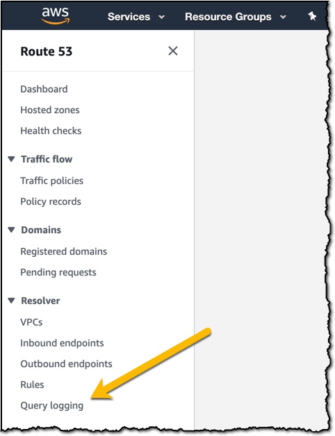
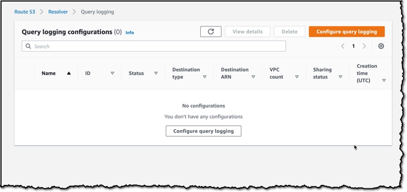
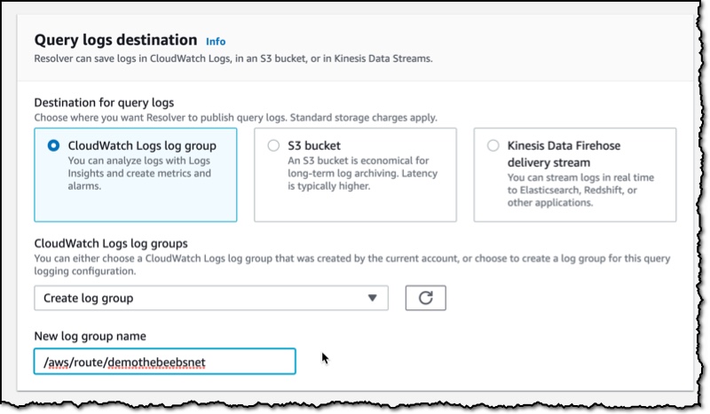
Route 53 Resolver Query Logs is available in all AWS Commercial Regions that support Route 53 Resolver Endpoints, and you can get started using either the API or the AWS Console. You do not pay for the Route 53 Resolver Query Logs, but you will pay for handling the logs in the destination service that you choose. So, for example, if you decided to use Amazon Kinesis Data Firehose, then you will incur the regular charges for handling logs with the Amazon Kinesis Data Firehose service.

Happy Logging

— Martin