Post Syndicated from Satyanarayana Adimula original https://aws.amazon.com/blogs/big-data/use-aws-glue-etl-to-perform-merge-partition-evolution-and-schema-evolution-on-apache-iceberg/
As enterprises collect increasing amounts of data from various sources, the structure and organization of that data often need to change over time to meet evolving analytical needs. However, altering schema and table partitions in traditional data lakes can be a disruptive and time-consuming task, requiring renaming or recreating entire tables and reprocessing large datasets. This hampers agility and time to insight.
Schema evolution enables adding, deleting, renaming, or modifying columns without needing to rewrite existing data. This is critical for fast-moving enterprises to augment data structures to support new use cases. For example, an ecommerce company may add new customer demographic attributes or order status flags to enrich analytics. Apache Iceberg manages these schema changes in a backward-compatible way through its innovative metadata table evolution architecture.
Similarly, partition evolution allows seamless adding, dropping, or splitting partitions. For instance, an ecommerce marketplace may initially partition order data by day. As orders accumulate, and querying by day becomes inefficient, they may split to day and customer ID partitions. Table partitioning organizes big datasets most efficiently for query performance. Iceberg gives enterprises the flexibility to incrementally adjust partitions rather than requiring tedious rebuild procedures. New partitions can be added in a fully compatible way without downtime or having to rewrite existing data files.
This post demonstrates how you can harness Iceberg, Amazon Simple Storage Service (Amazon S3), AWS Glue, AWS Lake Formation, and AWS Identity and Access Management (IAM) to implement a transactional data lake supporting seamless evolution. By allowing for painless schema and partition adjustments as data insights evolve, you can benefit from the future-proof flexibility needed for business success.
Overview of solution
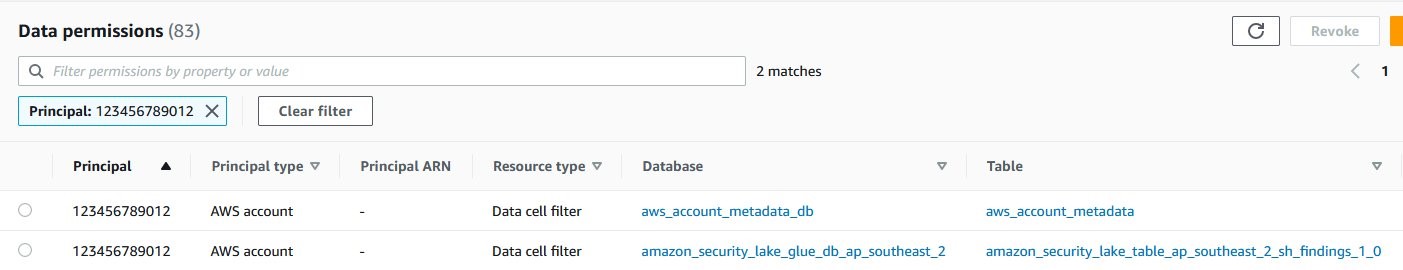
For our example use case, a fictional large ecommerce company processes thousands of orders each day. When orders are received, updated, cancelled, shipped, delivered, or returned, the changes are made in their on-premises system, and those changes need to be replicated to an S3 data lake so that data analysts can run queries through Amazon Athena. The changes can contain schema updates as well. Due to the security requirements of different organizations, they need to manage fine-grained access control for the analysts through Lake Formation.
The following diagram illustrates the solution architecture.

The solution workflow includes the following key steps:
- Ingest data from on premises into a Dropzone location using a data ingestion pipeline.
- Merge the data from the Dropzone location into Iceberg using AWS Glue.
- Query the data using Athena.
Prerequisites
For this walkthrough, you should have the following prerequisites:
Set up the infrastructure with AWS CloudFormation
To create your infrastructure with an AWS CloudFormation template, complete the following steps:
- Log in as an administrator to your AWS account.
- Open the AWS CloudFormation console.
- Choose Launch Stack:

- For Stack name, enter a name (for this post, icebergdemo1).
- Choose Next.
- Provide information for the following parameters:
DatalakeUserNameDatalakeUserPasswordDatabaseNameTableNameDatabaseLFTagKeyDatabaseLFTagValueTableLFTagKeyTableLFTagValue
- Choose Next.

- Choose Next again.
- In the Review section, review the values you entered.
- Select I acknowledge that AWS CloudFormation might create IAM resources with custom names and choose Submit.

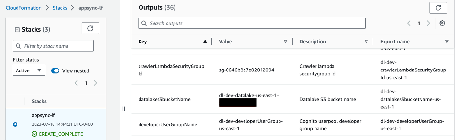
In a few minutes, the stack status will change to CREATE_COMPLETE.
You can go to the Outputs tab of the stack to see all the resources it has provisioned. The resources are prefixed with the stack name you provided (for this post, icebergdemo1).
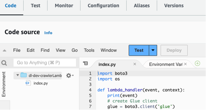
Create an Iceberg table using Lambda and grant access using Lake Formation
To create an Iceberg table and grant access on it, complete the following steps:
- Navigate to the Resources tab of the CloudFormation stack icebergdemo1 and search for logical ID named
LambdaFunctionIceberg. - Choose the hyperlink of the associated physical ID.


You’re redirected to the Lambda function icebergdemo1-Lambda-Create-Iceberg-and-Grant-access.

- On the Configuration tab, choose Environment variables in the left pane.


- On the Code tab, you can inspect the function code.
The function uses the AWS SDK for Python (Boto3) APIs to provision the resources. It assumes the provisioned data lake admin role to perform the following tasks:
- Grant DATA_LOCATION_ACCESS access to the data lake admin role on the registered data lake location
- Create Lake Formation Tags (LF-Tags)
- Create a database in the AWS Glue Data Catalog using the AWS Glue create_database API
- Assign LF-Tags to the database
- Grant DESCRIBE access on the database using LF-Tags to the data lake IAM user and AWS Glue ETL IAM role
- Create an Iceberg table using the AWS Glue create_table API:
- Assign LF-Tags to the table
- Grant DESCRIBE and SELECT on the Iceberg table LF-Tags for the data lake IAM user
- Grant ALL, DESCRIBE, SELECT, INSERT, DELETE, and ALTER access on the Iceberg table LF-Tags to the AWS Glue ETL IAM role
- On the Test tab, choose Test to run the function.


When the function is complete, you will see the message “Executing function: succeeded.”
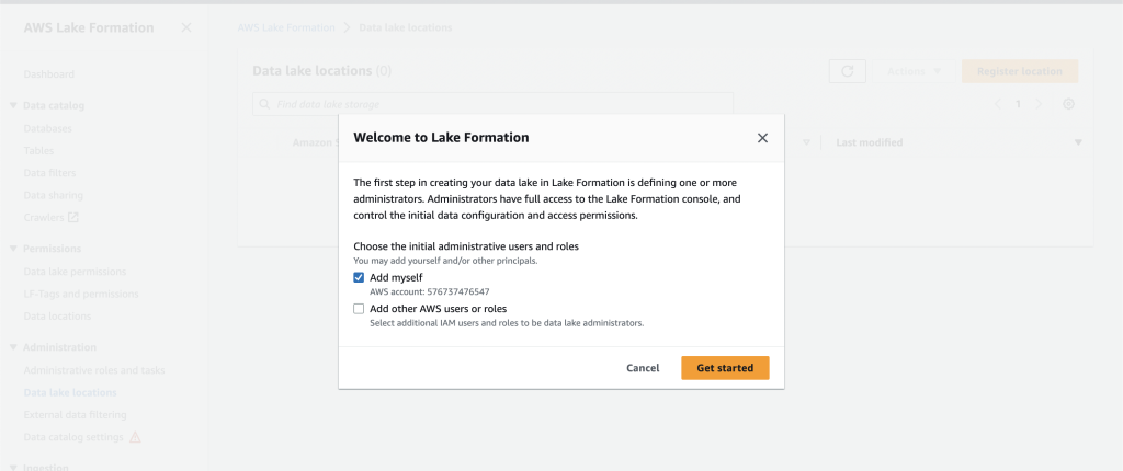
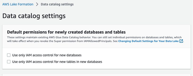
Lake Formation helps you centrally manage, secure, and globally share data for analytics and machine learning. With Lake Formation, you can manage fine-grained access control for your data lake data on Amazon S3 and its metadata in the Data Catalog.
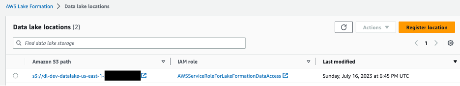
To add an Amazon S3 location as Iceberg storage in your data lake, register the location with Lake Formation. You can then use Lake Formation permissions for fine-grained access control to the Data Catalog objects that point to this location, and to the underlying data in the location.
The CloudFormation stack registered the data lake location.

Data location permissions in Lake Formation enable principals to create and alter Data Catalog resources that point to the designated registered Amazon S3 locations. Data location permissions work in addition to Lake Formation data permissions to secure information in your data lake.

Lake Formation tag-based access control (LF-TBAC) is an authorization strategy that defines permissions based on attributes. In Lake Formation, these attributes are called LF-Tags. You can attach LF-Tags to Data Catalog resources, Lake Formation principals, and table columns. You can assign and revoke permissions on Lake Formation resources using these LF-Tags. Lake Formation allows operations on those resources when the principal’s tag matches the resource tag.
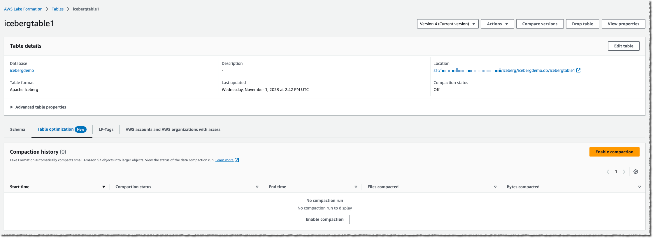
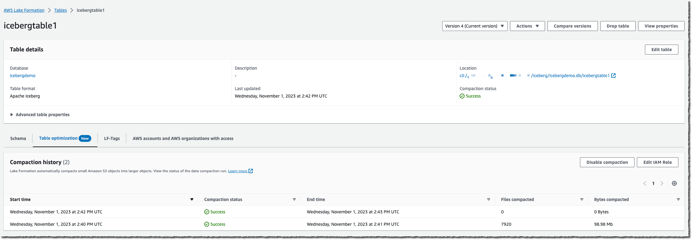
Verify the Iceberg table from the Lake Formation console
To verify the Iceberg table, complete the following steps:
- On the Lake Formation console, choose Databases in the navigation pane.
- Open the details page for
icebergdb1.
You can see the associated database LF-Tags.

- Choose Tables in the navigation pane.
- Open the details page for
ecomorders.
In the Table details section, you can observe the following:
- Table format shows as Apache Iceberg
- Table management shows as Managed by Data Catalog
- Location lists the data lake location of the Iceberg table
In the LF-Tags section, you can see the associated table LF-Tags.

In the Table details section, expand Advanced table properties to view the following:
metadata_locationpoints to the location of the Iceberg table’s metadata filetable_typeshows asICEBERG


On the Schema tab, you can view the columns defined on the Iceberg table.

Integrate Iceberg with the AWS Glue Data Catalog and Amazon S3
Iceberg tracks individual data files in a table instead of directories. When there is an explicit commit on the table, Iceberg creates data files and adds them to the table. Iceberg maintains the table state in metadata files. Any change in table state creates a new metadata file that atomically replaces the older metadata. Metadata files track the table schema, partitioning configuration, and other properties.
Iceberg requires file systems that support the operations to be compatible with object stores like Amazon S3.
Iceberg creates snapshots for the table contents. Each snapshot is a complete set of data files in the table at a point in time. Data files in snapshots are stored in one or more manifest files that contain a row for each data file in the table, its partition data, and its metrics.
The following diagram illustrates this hierarchy.

When you create an Iceberg table, it creates the metadata folder first and a metadata file in the metadata folder. The data folder is created when you load data into the Iceberg table.

Contents of the Iceberg metadata file
The Iceberg metadata file contains a lot of information, including the following:
- format-version –Version of the Iceberg table
- Location – Amazon S3 location of the table
- Schemas – Name and data type of all columns on the table
- partition-specs – Partitioned columns
- sort-orders – Sort order of columns
- properties – Table properties
- current-snapshot-id – Current snapshot
- refs – Table references
- snapshots – List of snapshots, each containing the following information:
- sequence-number – Sequence number of snapshots in chronological order (the highest number represents the current snapshot, 1 for the first snapshot)
- snapshot-id – Snapshot ID
- timestamp-ms – Timestamp when the snapshot was committed
- summary – Summary of changes committed
- manifest-list – List of manifests; this file name starts with snap-< snapshot-id >
- schema-id – Sequence number of the schema in chronological order (the highest number represents the current schema)
- snapshot-log – List of snapshots in chronological order
- metadata-log – List of metadata files in chronological order
The metadata file has all the historical changes to the table’s data and schema. Reviewing the contents on the metafile file directly can be a time-consuming task. Fortunately, you can query the Iceberg metadata using Athena.
Iceberg framework in AWS Glue
AWS Glue 4.0 supports Iceberg tables registered with Lake Formation. In the AWS Glue ETL jobs, you need the following code to enable the Iceberg framework:
For read/write access to underlying data, in addition to Lake Formation permissions, the AWS Glue IAM role to run the AWS Glue ETL jobs was granted lakeformation: GetDataAccess IAM permission. With this permission, Lake Formation grants the request for temporary credentials to access the data.
The CloudFormation stack provisioned the four AWS Glue ETL jobs for you. The name of each job starts with your stack name (icebergdemo1). Complete the following steps to view the jobs:
- Log in as an administrator to your AWS account.
- On the AWS Glue console, choose ETL jobs in the navigation pane.
- Search for jobs with
icebergdemo1in the name.


Merge data from Dropzone into the Iceberg table
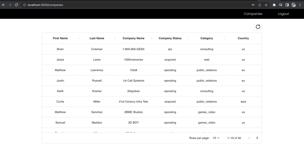
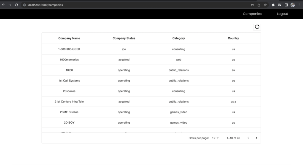
For our use case, the company ingests their ecommerce orders data daily from their on-premises location into an Amazon S3 Dropzone location. The CloudFormation stack loaded three files with sample orders for 3 days, as shown in the following figures. You see the data in the Dropzone location s3://icebergdemo1-s3bucketdropzone-kunftrcblhsk/data.


The AWS Glue ETL job icebergdemo1-GlueETL1-merge will run daily to merge the data into the Iceberg table. It has the following logic to add or update the data on Iceberg:
- Create a Spark DataFrame from input data:
- For a new order, add it to the table
- If the table has a matching order, update the status and
shipping_id:
Complete the following steps to run the AWS Glue merge job:
- On the AWS Glue console, choose ETL jobs in the navigation pane.
- Select the ETL job
icebergdemo1-GlueETL1-merge. - On the Actions dropdown menu, choose Run with parameters.
- On the Run parameters page, go to Job parameters.
- For the
--dropzone_pathparameter, provide the S3 location of the input data (icebergdemo1-s3bucketdropzone-kunftrcblhsk/data/merge1). - Run the job to add all the orders: 1001, 1002, 1003, and 1004.
- For the
--dropzone_path parameter, change the S3 location toicebergdemo1-s3bucketdropzone-kunftrcblhsk/data/merge2. - Run the job again to add orders 2001 and 2002, and update orders 1001, 1002, and 1003.
- For the
--dropzone_pathparameter, change the S3 location toicebergdemo1-s3bucketdropzone-kunftrcblhsk/data/merge3. - Run the job again to add order 3001 and update orders 1001, 1003, 2001, and 2002.
Go to the data folder of table to see the data files written by Iceberg when you merged the data into the table using the Glue ETL job icebergdemo1-GlueETL1-merge.

Query Iceberg using Athena
The CloudFormation stack created the IAM user iceberguser1, which has read access on the Iceberg table using LF-Tags. To query Iceberg using Athena via this user, complete the following steps:
- Log in as
iceberguser1to the AWS Management Console. - On the Athena console, choose Workgroups in the navigation pane.
- Locate the workgroup that CloudFormation provisioned (
icebergdemo1-workgroup) - Verify Athena engine version 3.
The Athena engine version 3 supports Iceberg file formats, including Parquet, ORC, and Avro.

- Go to the Athena query editor.
- Choose the workgroup icebergdemo1-workgroup on the dropdown menu.
- For Database, choose
icebergdb1. You will see the tableecomorders. - Run the following query to see the data in the Iceberg table:

- Run the following query to see table’s current partitions:


Partition-spec describes how table is partitioned. In this example, there are no partitioned fields because you didn’t define any partitions on the table.
Iceberg partition evolution
You may need to change your partition structure; for example, due to trend changes of common query patterns in downstream analytics. A change of partition structure for traditional tables is a significant operation that requires an entire data copy.
Iceberg makes this straightforward. When you change the partition structure on Iceberg, it doesn’t require you to rewrite the data files. The old data written with earlier partitions remains unchanged. New data is written using the new specifications in a new layout. Metadata for each of the partition versions is kept separately.
Let’s add the partition field category to the Iceberg table using the AWS Glue ETL job icebergdemo1-GlueETL2-partition-evolution:
On the AWS Glue console, run the ETL job icebergdemo1-GlueETL2-partition-evolution. When the job is complete, you can query partitions using Athena.


You can see the partition field category, but the partition values are null. There are no new data files in the data folder, because partition evolution is a metadata operation and doesn’t rewrite data files. When you add or update data, you will see the corresponding partition values populated.
Iceberg schema evolution
Iceberg supports in-place table evolution. You can evolve a table schema just like SQL. Iceberg schema updates are metadata changes, so no data files need to be rewritten to perform the schema evolution.
To explore the Iceberg schema evolution, run the ETL job icebergdemo1-GlueETL3-schema-evolution via the AWS Glue console. The job runs the following SparkSQL statements:
In the Athena query editor, run the following query:

You can verify the schema changes to the Iceberg table:
- A new column has been added called
shipping_carrier - The column
shipping_idhas been renamed totracking_number - The data type of the column
ordernumhas changed from int to bigint

Positional update
The data in tracking_number contains the shipping carrier concatenated with the tracking number. Let’s assume that we want to split this data in order to keep the shipping carrier in the shipping_carrier field and the tracking number in the tracking_number field.
On the AWS Glue console, run the ETL job icebergdemo1-GlueETL4-update-table. The job runs the following SparkSQL statement to update the table:
Query the Iceberg table to verify the updated data on tracking_number and shipping_carrier.

Now that the data has been updated on the table, you should see the partition values populated for category:

Clean up
To avoid incurring future charges, clean up the resources you created:
- On the Lambda console, open the details page for the function
icebergdemo1-Lambda-Create-Iceberg-and-Grant-access. - In the Environment variables section, choose the key
Task_To_Performand update the value toCLEANUP. - Run the function, which drops the database, table, and their associated LF-Tags.
- On the AWS CloudFormation console, delete the stack icebergdemo1.
Conclusion
In this post, you created an Iceberg table using the AWS Glue API and used Lake Formation to control access on the Iceberg table in a transactional data lake. With AWS Glue ETL jobs, you merged data into the Iceberg table, and performed schema evolution and partition evolution without rewriting or recreating the Iceberg table. With Athena, you queried the Iceberg data and metadata.
Based on the concepts and demonstrations from this post, you can now build a transactional data lake in an enterprise using Iceberg, AWS Glue, Lake Formation, and Amazon S3.
About the Author
 Satya Adimula is a Senior Data Architect at AWS based in Boston. With over two decades of experience in data and analytics, Satya helps organizations derive business insights from their data at scale.


 Amy Tseng is a Managing Director of Data and Analytics(DnA) Integration at BMO. She is one of the AWS Data Hero. She has over 7 years of experiences in Data and Analytics Cloud migrations in AWS. Outside of work, Amy loves traveling and hiking.
 Jack Lin is a Director of Engineering on the Data Platform at BMO. He has over 20 years of experience working in platform engineering and software engineering. Outside of work, Jack loves playing soccer, watching football games and traveling.
 Regis Chow is a Director of DnA Integration at BMO. He has over 5 years of experience working in the cloud and enjoys solving problems through innovation in AWS. Outside of work, Regis loves all things outdoors, he is especially passionate about golf and lawn care.
 Nishchai JM is an Analytics Specialist Solutions Architect at Amazon Web services. He specializes in building Big-data applications and help customer to modernize their applications on Cloud. He thinks Data is new oil and spends most of his time in deriving insights out of the Data.
 Harshida Patel is a Principal Solutions Architect, Analytics with AWS.
 Raghu Kuppala is an Analytics Specialist Solutions Architect experienced working in the databases, data warehousing, and analytics space. Outside of work, he enjoys trying different cuisines and spending time with his family and friends.


 Toney Thomas is a Data Architect and Data Engineering Lead at Bluestone, renowned for his role in envisioning and coining the company’s pioneering data strategy. With a strategic focus on harnessing the power of advanced technology to tackle intricate business challenges, Toney leads a dynamic team of Data Engineers, Reporting Engineers, Quality Assurance specialists, and Business Analysts at Bluestone. His leadership extends to driving the implementation of robust data governance frameworks across diverse organizational units. Under his guidance, Bluestone has achieved remarkable success, including the deployment of innovative platforms such as a fully governed data mesh business data system with embedded data quality mechanisms, aligning seamlessly with the organization’s commitment to data democratization and excellence.
 Ben Vengerovsky is a Data Platform Product Manager at Bluestone. He is passionate about using cloud technology to revolutionize the company’s data infrastructure. With a background in mortgage lending and a deep understanding of AWS services, Ben specializes in designing scalable and efficient data solutions that drive business growth and enhance customer experiences. He thrives on collaborating with cross-functional teams to translate business requirements into innovative technical solutions that empower data-driven decision-making.
 Rada Stanic is a Chief Technologist at Amazon Web Services, where she helps ANZ customers across different segments solve their business problems using AWS Cloud technologies. Her special areas of interest are data analytics, machine learning/AI, and application modernization.


 Kanwar Bajwa is an Enterprise Support Lead at AWS who works with customers to optimize their use of AWS services and achieve their business objectives.
 Swapna Bandla is a Senior Solutions Architect in the AWS Analytics Specialist SA Team. Swapna has a passion towards understanding customers data and analytics needs and empowering them to develop cloud-based well-architected solutions. Outside of work, she enjoys spending time with her family.


 Alternatively, you can run the following command:


 Harshida Patel is a Analytics Specialist Principal Solutions Architect, with AWS.
 Srividya Parthasarathy is a Senior Big Data Architect on the AWS Lake Formation team. She enjoys building data mesh solutions and sharing them with the community.
 Maneesh Sharma is a Senior Database Engineer at AWS with more than a decade of experience designing and implementing large-scale data warehouse and analytics solutions. He collaborates with various Amazon Redshift Partners and customers to drive better integration.
 Poulomi Dasgupta is a Senior Analytics Solutions Architect with AWS. She is passionate about helping customers build cloud-based analytics solutions to solve their business problems. Outside of work, she likes travelling and spending time with her family.


 Aarthi Srinivasan is a Senior Big Data Architect with AWS Lake Formation. She likes building data lake solutions for AWS customers and partners. When not on the keyboard, she explores the latest science and technology trends and spends time with her family.
 Leon Stigter is a Senior Technical Product Manager with AWS Lake Formation. Leon’s focus is on helping developers build data lakes faster, with seamless connectivity to analytical tools, to transform data into game-changing insights. Leon is interested in data and serverless technologies, and enjoys exploring different cities on his mission to taste cheesecake everywhere he goes.


 Raymond Lai is a Senior Solutions Architect who specializes in catering to the needs of large enterprise customers. His expertise lies in assisting customers with migrating intricate enterprise systems and databases to AWS, constructing enterprise data warehousing and data lake platforms. Raymond excels in identifying and designing solutions for AI/ML use cases, and he has a particular focus on AWS Serverless solutions and Event Driven Architecture design.
 Bin Wang, PhD, is a Senior Analytic Specialist Solutions Architect at AWS, boasting over 12 years of experience in the ML industry, with a particular focus on advertising. He possesses expertise in natural language processing (NLP), recommender systems, diverse ML algorithms, and ML operations. He is deeply passionate about applying ML/DL and big data techniques to solve real-world problems.
 Aditya Shah is a Software Development Engineer at AWS. He is interested in Databases and Data warehouse engines and has worked on performance optimisations, security compliance and ACID compliance for engines like Apache Hive and Apache Spark.
 Melody Yang is a Senior Big Data Solution Architect for Amazon EMR at AWS. She is an experienced analytics leader working with AWS customers to provide best practice guidance and technical advice in order to assist their success in data transformation. Her areas of interests are open-source frameworks and automation, data engineering and DataOps.


 Sandeep Adwankar is a Senior Technical Product Manager at AWS. Based in the California Bay Area, he works with customers around the globe to translate business and technical requirements into products that enable customers to improve how they manage, secure, and access data.
 Navnit Shukla serves as an AWS Specialist Solution Architect with a focus on Analytics. He possesses a strong enthusiasm for assisting clients in discovering valuable insights from their data. Through his expertise, he constructs innovative solutions that empower businesses to arrive at informed, data-driven choices. Notably, Navnit Shukla is the accomplished author of the book titled Data Wrangling on AWS. He can be reached via


 Ramkumar Nottath is a Principal Solutions Architect at AWS focusing on Analytics services. He enjoys working with various customers to help them build scalable, reliable big data and analytics solutions. His interests extend to various technologies such as analytics, data warehousing, streaming, data governance, and machine learning. He loves spending time with his family and friends.
 Mert Hocanin is a Principal Big Data Architect at AWS within the AWS Lake Formation Product team. He has been with Amazon for over 10 years, and enjoys helping customers build their data lakes with a focus on governance on a wide variety of services. When he isn’t helping customers build data lakes, he spends his time with his family and traveling.


 Ashley Zhou is a Software Development Engineer at AWS. She is interested in data analytics and distributed systems.
 Srividya Parthasarathy is a Senior Big Data Architect on the AWS Lake Formation team. She enjoys building analytics and data mesh solutions on AWS and sharing them with the community.


 Shoukat Ghouse is a Senior Big Data Specialist Solutions Architect at AWS. He helps customers around the world build robust, efficient and scalable data platforms on AWS leveraging AWS analytics services like AWS Glue, AWS Lake Formation, Amazon Athena and Amazon EMR.
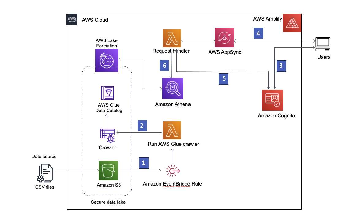
 Rana Dutt is a Principal Solutions Architect at Amazon Web Services. He has a background in architecting scalable software platforms for financial services, healthcare, and telecom companies, and is passionate about helping customers build on AWS.
 Ranjith Rayaprolu is a Senior Solutions Architect at AWS working with customers in the Pacific Northwest. He helps customers design and operate Well-Architected solutions in AWS that address their business problems and accelerate the adoption of AWS services. He focuses on AWS security and networking technologies to develop solutions in the cloud across different industry verticals. Ranjith lives in the Seattle area and loves outdoor activities.
 Justin Leto is a Sr. Solutions Architect at Amazon Web Services with specialization in databases, big data analytics, and machine learning. His passion is helping customers achieve better cloud adoption. In his spare time, he enjoys offshore sailing and playing jazz piano. He lives in New York City with his wife and baby daughter.


 Aarthi Srinivasan is a Senior Big Data Architect with AWS Lake Formation. She likes building data lake solutions for AWS customers and partners. When not on the keyboard, she explores the latest science and technology trends and spends time with her family.


 Aarthi Srinivasan is a Senior Big Data Architect with AWS Lake Formation. She likes building data lake solutions for AWS customers and partners. When not on the keyboard, she explores the latest science and technology trends and spends time with her family.


 Yadukishore Tatavarthi is a Senior Partner Solutions Architect supporting Healthcare and life science customers at Amazon Web Services. He has been helping the customers over the last 20 years in building the enterprise data strategies, advising customers on cloud implementations, migrations, reference architecture creation, data modeling best practices, data lake/warehouses architecture, and other technical processes.
 Sudhir Gupta is a Principal Partner Solutions Architect, Analytics Specialist at AWS with over 18 years of experience in Databases and Analytics. He helps AWS partners and customers design, implement, and migrate large-scale data & analytics (D&A) workloads. As a trusted advisor to partners, he enables partners globally on AWS D&A services, builds solutions/accelerators, and leads go-to-market initiatives
 Deepak Singh is a Senior Solutions Architect at Amazon Web Services with 20+ years of experience in Data & AIA. He enjoys working with AWS partners and customers on building scalable analytical solutions for their business outcomes. When not at work, he loves spending time with family or exploring new technologies in analytics and AI space.


 Praveen Kumar is an Analytics Solution Architect at AWS with expertise in designing, building, and implementing modern data and analytics platforms using cloud-native services. His areas of interests are serverless technology, modern cloud data warehouses, streaming, and ML applications.
 Srividya Parthasarathy is a Senior Big Data Architect on the AWS Lake Formation team. She enjoys building data mesh solutions and sharing them with the community.
 Paul Villena is an Analytics Solutions Architect in AWS with expertise in building modern data and analytics solutions to drive business value. He works with customers to help them harness the power of the cloud. His areas of interests are infrastructure as code, serverless technologies, and coding in Python.
 Mostafa Safipour is a Solutions Architect at AWS based out of Sydney. He works with customers to realize business outcomes using technology and AWS. Over the past decade, he has helped many large organizations in the ANZ region build their data, digital, and enterprise workloads on AWS.