Tag Archives: Customer Solutions

Using and Managing Security Groups on AWS Snowball Edge devices

Post Syndicated from Macey Neff original https://aws.amazon.com/blogs/compute/using-and-managing-security-groups-on-aws-snowball-edge-devices/

This blog post is written by Jared Novotny & Tareq Rajabi, Specialist Hybrid Edge Solution Architects. 

The AWS Snow family of products are purpose-built devices that allow petabyte-scale movement of data from on-premises locations to AWS Regions. Snow devices also enable customers to run Amazon Elastic Compute Cloud (Amazon EC2) instances with Amazon Elastic Block Storage (Amazon EBS), and Amazon Simple Storage Service (Amazon S3) in edge locations.

Security groups are used to protect EC2 instances by controlling ingress and egress traffic. Once a security group is created and associated with an instance, customers can add ingress and egress rules to control data flow. Just like the default VPC in a region, there is a default security group on Snow devices. A default security group is applied when an instance is launched and no other security group is specified.  This default security group in a region allows all inbound traffic from network interfaces and instances that are assigned to the same security group, and allows and all outbound traffic. On Snowball Edge, the default security group allows all inbound and outbound traffic.

In this post, we will review the tools and commands required to create, manage and use security groups on the Snowball Edge device.

Some things to keep in mind:

  1. AWS Snowball Edge is limited to 50 security groups.
  2. An instance will only have one security group, but each group can have a total of 120 rules. This is comprised of 60 inbound and 60 outbound rules.
  3. Security groups can only have allow statements to allow network traffic.
  4. Deny statements aren’t allowed.
  5. Some commands in the Snowball Edge client (AWS CLI) don’t provide an output.
  6. AWS CLI commands can use the name or the security group ID.

Prerequisites and tools

Customers must place an order for Snowball Edge from their AWS Console to be able to run the following AWS CLI commands and configure security groups to protect their EC2 instances.

The AWS Snowball Edge client is a standalone terminal application that customers can run on their local servers and workstations to manage and operate their Snowball Edge devices. It supports Windows, Mac, and Linux systems.

AWS OpsHub is a graphical user interface that you can use to manage your AWS Snowball devices. Furthermore, it’s the easiest tool to use to unlock Snowball Edge devices. It can also be used to configure the device, launch instances, manage storage, and provide monitoring.

Customers can download and install the Snowball Edge client and AWS OpsHub from AWS Snowball resources.

Getting Started

To get started, when a Snow device arrives at a customer site, the customer must unlock the device and launch an EC2 instance. This can be done via AWS OpsHub or the AWS Snowball Edge Client. AWS Snow Family of devices support both Virtual Network Interfaces (VNI) and Direct Network interfaces (DNI), customers should review the types of interfaces before deciding which one is best for their use case. Note that security groups are only supported with VNIs, so that is what was used in this post. A post explaining how to use these interfaces should be reviewed before proceeding.

Viewing security group information

Once the AWS Snowball Edge is unlocked, configured, and has an EC2 instance running, we can dig deeper into using security groups to act as a virtual firewall and control incoming and outgoing traffic.

Although the AWS OpsHub tool provides various functionalities for compute and storage operations, it can only be used to view the name of the security group associated to an instance in a Snowball Edge device:

view the name of the security group associated to an instance in a Snowball Edge device

Every other interaction with security groups must be through the AWS CLI.

The following command shows how to easily read the outputs describing the protocols, sources, and destinations. This particular command will show information about the default security group, which allows all inbound and outbound traffic on EC2 instances running on the Snowball Edge.

In the following sections we review the most common commands with examples and outputs.

View (all) existing security groups:

aws ec2 describe-security-groups --endpoint Http://MySnowIPAddress:8008 --profile SnowballEdge
{
    "SecurityGroups": [
        {
            "Description": "default security group",
            "GroupName": "default",
            "IpPermissions": [
                {
                    "IpProtocol": "-1",
                    "IpRanges": [
                        {
                            "CidrIp": "0.0.0.0/0"
                        }
                    ]
                }
            ],
            "GroupId": "s.sg-8ec664a23666db719",
            "IpPermissionsEgress": [
                {
                    "IpProtocol": "-1",
                    "IpRanges": [
                        {
                            "CidrIp": "0.0.0.0/0"
                        }
                    ]
                }
            ]
        }
    ]
}

Create new security group:

aws ec2 create-security-group --group-name allow-ssh--description "allow only ssh inbound" --endpoint Http://MySnowIPAddress:8008 --profile SnowballEdge

The output returns a GroupId:

{  "GroupId": "s.sg-8f25ee27cee870b4a" }

Add port 22 ingress to security group:

aws ec2 authorize-security-group-ingress --group-ids.sg-8f25ee27cee870b4a --protocol tcp --port 22 --cidr 10.100.10.0/24 --endpoint Http://MySnowIPAddress:8008 --profile SnowballEdge

{    "Return": true }

Note that if you’re using the default security group, then the outbound rule is still to allow all traffic.

Revoke port 22 ingress rule from security group

aws ec2 revoke-security-group-ingress --group-ids.sg-8f25ee27cee870b4a --ip-permissions IpProtocol=tcp,FromPort=22,ToPort=22, IpRanges=[{CidrIp=10.100.10.0/24}] --endpoint Http://MySnowIPAddress:8008 --profile SnowballEdge

{ "Return": true }

Revoke default egress rule:

aws ec2 revoke-security-group-egress --group-ids.sg-8f25ee27cee870b4a  --ip-permissions IpProtocol="-1",IpRanges=[{CidrIp=0.0.0.0/0}] --endpoint Http://MySnowIPAddress:8008 --profile SnowballEdge

{ "Return": true }

Note that this rule will remove all outbound ephemeral ports.

Add default outbound rule (revoked above):

aws ec2 authorize-security-group-egress --group-id s.sg-8f25ee27cee870b4a --ip-permissions IpProtocol="-1", IpRanges=[{CidrIp=0.0.0.0/0}] --endpoint Http://MySnowIPAddress:8008 --profile SnowballEdge

{  "Return": true }

Changing an instance’s existing security group:

aws ec2 modify-instance-attribute --instance-id s.i-852971d05144e1d63 --groups s.sg-8f25ee27cee870b4a --endpoint Http://MySnowIPAddress:8008 --profile SnowballEdge

Note that this command produces no output. We can verify that it worked with the “aws ec2 describe-instances” command. See the example as follows (command output simplified):

aws ec2 describe-instances --instance-id s.i-852971d05144e1d63 --endpoint Http://MySnowIPAddress:8008 --profile SnowballEdge


    "Reservations": [{
            "Instances": [{
                    "InstanceId": "s.i-852971d05144e1d63",
                    "InstanceType": "sbe-c.2xlarge",
                    "LaunchTime": "2022-06-27T14:58:30.167000+00:00",
                    "PrivateIpAddress": "34.223.14.193",
                    "PublicIpAddress": "10.100.10.60",
                    "SecurityGroups": [
                        {
                            "GroupName": "allow-ssh",
                            "GroupId": "s.sg-8f25ee27cee870b4a"
                        }      ], }  ] }

Changing and instance’s security group back to default:

aws ec2 modify-instance-attribute --instance-ids.i-852971d05144e1d63 --groups s.sg-8ec664a23666db719 --endpoint Http://MySnowIPAddress:8008 --profile SnowballEdge

Note that this command produces no output. You can verify that it worked with the “aws ec2 describe-instances” command. See the example as follows:

aws ec2 describe-instances –instance-ids.i-852971d05144e1d63 –endpoint Https://MySnowIPAddress:8008 –profile SnowballEdge

{
    "Reservations": [
        {  "Instances": [ {
                    "AmiLaunchIndex": 0,
                    "ImageId": "s.ami-8b0223704ca8f08b2",
                    "InstanceId": "s.i-852971d05144e1d63",
                    "InstanceType": "sbe-c.2xlarge",
                    "LaunchTime": "2022-06-27T14:58:30.167000+00:00",
                    "PrivateIpAddress": "34.223.14.193",
                    "PublicIpAddress": "10.100.10.60",
                             "SecurityGroups": [
                        {
                            "GroupName": "default",
                            "GroupId": "s.sg-8ec664a23666db719" ] }

Delete security group:

aws ec2 delete-security-group --group-ids.sg-8f25ee27cee870b4a --endpoint Http://MySnowIPAddress:8008 --profile SnowballEdge

Sample walkthrough to add a SSH Security Group

As an example, assume a single EC2 instance “A” running on a Snowball Edge device. By default, all traffic is allowed to EC2 instance “A”. As per the following diagram, we want to tighten security and allow only the management PC to SSH to the instance.

1. Create an SSH security group:

aws ec2 create-security-group --group-name MySshGroup--description “ssh access” --endpoint Http://MySnowIPAddress:8008 --profile SnowballEdge

2. This will return a “GroupId” as an output:

{   "GroupId": "s.sg-8a420242d86dbbb89" }

3. After the creation of the security group, we must allow port 22 ingress from the management PC’s IP:

aws ec2 authorize-security-group-ingress --group-name MySshGroup -- protocol tcp --port 22 -- cidr 192.168.26.193/32 --endpoint Http://MySnowIPAddress:8008 --profile SnowballEdge

4. Verify that the security group has been created:

aws ec2 describe-security-groups ––group-name MySshGroup –endpoint Http://MySnowIPAddress:8008 --profile SnowballEdge

{
	“SecurityGroups”:   [
		{
			“Description”: “SG for web servers”,
			“GroupName”: :MySshGroup”,
			“IpPermissinos”:  [
				{ “FromPort”: 22,
			 “IpProtocol”: “tcp”,
			 “IpRanges”: [
			{
				“CidrIp”: “192.168.26.193.32/32”
						} ],
					“ToPort”:  22 }],}

5. After the security group has been created, we must associate it with the instance:

aws ec2 modify-instance-attribute –-instance-id s.i-8f7ab16867ffe23d4 –-groups s.sg-8a420242d86dbbb89 --endpoint Http://MySnowIPAddress:8008 --profile SnowballEdge

6. Optionally, we can delete the Security Group after it is no longer required:

aws ec2 delete-security-group --group-id s.sg-8a420242d86dbbb89 --endpoint Http://MySnowIPAddress:8008 --profile SnowballEdge

Note that for the above association, the instance ID is an output of the “aws ec2 describe-instances” command, while the security group ID is an output of the “describe-security-groups” command (or the “GroupId” returned by the console in Step 2 above).

Conclusion

This post addressed the most common commands used to create and manage security groups with the AWS Snowball Edge device. We explored the prerequisites, tools, and commands used to view, create, and modify security groups to ensure the EC2 instances deployed on AWS Snowball Edge are restricted to authorized users. We concluded with a simple walkthrough of how to restrict access to an EC2 instance over SSH from a single IP address. If you would like to learn more about the Snowball Edge product, there are several resources available on the AWS Snow Family site.

How Ontraport reduced data processing cost by 80% with AWS Glue

Post Syndicated from Elijah Ball original https://aws.amazon.com/blogs/big-data/how-ontraport-reduced-data-processing-cost-by-80-with-aws-glue/

This post is written in collaboration with Elijah Ball from Ontraport.

Customers are implementing data and analytics workloads in the AWS Cloud to optimize cost. When implementing data processing workloads in AWS, you have the option to use technologies like Amazon EMR or serverless technologies like AWS Glue. Both options minimize the undifferentiated heavy lifting activities like managing servers, performing upgrades, and deploying security patches and allow you to focus on what is important: meeting core business objectives. The difference between both approaches can play a critical role in enabling your organization to be more productive and innovative, while also saving money and resources.

Services like Amazon EMR focus on offering you flexibility to support data processing workloads at scale using frameworks you’re accustomed to. For example, with Amazon EMR, you can choose from multiple open-source data processing frameworks such as Apache Spark, Apache Hive, and Presto, and fine-tune workloads by customizing things such as cluster instance types on Amazon Elastic Compute Cloud (Amazon EC2) or use containerized environments running on Amazon Elastic Kubernetes Service (Amazon EKS). This option is best suited when migrating workloads from big data environments like Apache Hadoop or Spark, or when used by teams that are familiar with open-source frameworks supported on Amazon EMR.

Serverless services like AWS Glue minimize the need to think about servers and focus on offering additional productivity and DataOps tooling for accelerating data pipeline development. AWS Glue is a serverless data integration service that helps analytics users discover, prepare, move, and integrate data from multiple sources via a low-code or no-code approach. This option is best suited when organizations are resource-constrained and need to build data processing workloads at scale with limited expertise, allowing them to expedite development and reduced Total Cost of Ownership (TCO).

In this post, we show how our AWS customer Ontraport evaluated the use of AWS Glue and Amazon EMR to reduce TCO, and how they reduced their storage cost by 92% and their processing cost by 80% with only one full-time developer.

Ontraport’s workload and solution

Ontraport is a CRM and automation service that powers businesses’ marketing, sales and operations all in one place—empowering businesses to grow faster and deliver more value to their customers.

Log processing and analysis is critical to Ontraport. It allows them to provide better services and insight to customers such as email campaign optimization. For example, email logs alone record 3–4 events for every one of the 15–20 million messages Ontraport sends on behalf of their clients each day. Analysis of email transactions with providers such as Google and Microsoft allow Ontraport’s delivery team to optimize open rates for the campaigns of clients with big contact lists.

Some of the big log contributors are web server and CDN events, email transaction records, and custom event logs within Ontraport’s proprietary applications. The following is a sample breakdown of their daily log contributions:

Cloudflare request logs 75 million records
CloudFront request logs 2 million records
Nginx/Apache logs 20 million records
Email logs 50 million records
General server logs 50 million records
Ontraport app logs 6 million records

Ontraport’s solution uses Amazon Kinesis and Amazon Kinesis Data Firehose to ingest log data and write recent records into an Amazon OpenSearch Service database, from where analysts and administrators can analyze the last 3 months of data. Custom application logs record interactions with the Ontraport CRM so client accounts can be audited or recovered by the customer support team. Originally, all logs were retained back to 2018. Retention is multi-leveled by age:

  • Less than 1 week – OpenSearch hot storage
  • Between 1 week and 3 months – OpenSearch cold storage
  • More than 3 months – Extract, transform, and load (ETL) processed in Amazon Simple Storage Service (Amazon S3), available through Amazon Athena

The following diagram shows the architecture of their log processing and analytics data pipeline.

Evaluating the optimal solution

In order to optimize storage and analysis of their historical records in Amazon S3, Ontraport implemented an ETL process to transform and compress TSV and JSON files into Parquet files with partitioning by the hour. The compression and transformation helped Ontraport reduce their S3 storage costs by 92%.

In phase 1, Ontraport implemented an ETL workload with Amazon EMR. Given the scale of their data (hundreds of billions of rows) and only one developer, Ontraport’s first attempt at the Apache Spark application required a 16-node EMR cluster with r5.12xlarge core and task nodes. The configuration allowed the developer to process 1 year of data and minimize out-of-memory issues with a rough version of the Spark ETL application.

To help optimize the workload, Ontraport reached out to AWS for optimization recommendations. There were a considerable number of options to optimize the workload within Amazon EMR, such as right-sizing Amazon Elastic Compute Cloud (Amazon EC2) instance type based on workload profile, modifying Spark YARN memory configuration, and rewriting portions of the Spark code. Considering the resource constraints (only one full-time developer), the AWS team recommended exploring similar logic with AWS Glue Studio.

Some of the initial benefits with using AWS Glue for this workload include the following:

  • AWS Glue has the concept of crawlers that provides a no-code approach to catalog data sources and identify schema from multiple data sources, in this case, Amazon S3.
  • AWS Glue provides built-in data processing capabilities with abstract methods on top of Spark that reduce the overhead required to develop efficient data processing code. For example, AWS Glue supports a DynamicFrame class corresponding to a Spark DataFrame that provides additional flexibility when working with semi-structured datasets and can be quickly transformed into a Spark DataFrame. DynamicFrames can be generated directly from crawled tables or directly from files in Amazon S3. See the following example code:
    dyf = glueContext.create_dynamic_frame.from_options(
    
    connection_type = 's3',
    connection_options = {'paths': [s3://<bucket/paths>]},
    format = 'json')

  • It minimizes the need for Ontraport to right-size instance types and auto scaling configurations.
  • Using AWS Glue Studio interactive sessions allows Ontraport to quickly iterate when code changes where needed when detecting historical log schema evolution.

Ontraport had to process 100 terabytes of log data. The cost of processing each terabyte with the initial configuration was approximately $500. That cost came down to approximately $100 per terabyte after using AWS Glue. By using AWS Glue and AWS Glue Studio, Ontraport’s cost of processing the jobs was reduced by 80%.

Diving deep into the AWS Glue workload

Ontraport’s first AWS Glue application was a PySpark workload that ingested data from TSV and JSON files in Amazon S3, performed basic transformations on timestamp fields, and converted the data types of a couple fields. Finally, it writes output data into a curated S3 bucket as compressed Parquet files of approximately 1 GB in size and partitioned in 1-hour intervals to optimize for queries with Athena.

With an AWS Glue job configured with 10 workers of the type G.2x configuration, Ontraport was able to process approximately 500 million records in less than 60 minutes. When processing 10 billion records, they were able to increase the job configuration to a maximum of 100 workers with auto scaling enabled to complete the job within 1 hour.

What’s next?

Ontraport has been able to process logs as early as 2018. The team is updating the processing code to allow for scenarios of schema evolution (such as new fields) and parameterized some components to fully automate the batch processing. They are also looking to fine-tune the number of provisioned AWS Glue workers to obtain optimal price-performance.

Conclusion

In this post, we showed you how Ontraport used AWS Glue to help reduce development overhead and simplify development efforts for their ETL workloads with only one full-time developer. Although services like Amazon EMR offer great flexibility and optimization, the ease of use and simplification in AWS Glue often offer a faster path for cost-optimization and innovation for small and medium businesses. For more information about AWS Glue, check out Getting Started with AWS Glue.


About the Authors

Elijah Ball has been a Sys Admin at Ontraport for 12 years. He is currently working to move Ontraport’s production workloads to AWS and develop data analysis strategies for Ontraport.

Pablo Redondo is a Principal Solutions Architect at Amazon Web Services. He is a data enthusiast with over 16 years of FinTech and healthcare industry experience and is a member of the AWS Analytics Technical Field Community (TFC). Pablo has been leading the AWS Gain Insights Program to help AWS customers achieve better insights and tangible business value from their data analytics initiatives.

Vikram Honmurgi is a Customer Solutions Manager at Amazon Web Services. With over 15 years of software delivery experience, Vikram is passionate about assisting customers and accelerating their cloud journey, delivering frictionless migrations, and ensuring our customers capture the full potential and sustainable business advantages of migrating to the AWS Cloud.

Estimating Scope 1 Carbon Footprint with Amazon Athena

Post Syndicated from Thomas Burns original https://aws.amazon.com/blogs/big-data/estimating-scope-1-carbon-footprint-with-amazon-athena/

Today, more than 400 organizations have signed The Climate Pledge, a commitment to reach net-zero carbon by 2040. Some of the drivers that lead to setting explicit climate goals include customer demand, current and anticipated government relations, employee demand, investor demand, and sustainability as a competitive advantage. AWS customers are increasingly interested in ways to drive sustainability actions. In this blog, we will walk through how we can apply existing enterprise data to better understand and estimate Scope 1 carbon footprint using Amazon Simple Storage Service (S3) and Amazon Athena, a serverless interactive analytics service that makes it easy to analyze data using standard SQL.

The Greenhouse Gas Protocol

The Greenhouse Gas Protocol (GHGP) provides standards for measuring and managing global warming impacts from an organization’s operations and value chain.

The greenhouse gases covered by the GHGP are the seven gases required by the UNFCCC/Kyoto Protocol (which is often called the “Kyoto Basket”). These gases are carbon dioxide (CO2), methane (CH4), nitrous oxide (N2O), the so-called F-gases (hydrofluorocarbons and perfluorocarbons), sulfur hexafluoride (SF6) nitrogen trifluoride (NF3). Each greenhouse gas is characterized by its global warming potential (GWP), which is determined by the gas’s greenhouse effect and its lifetime in the atmosphere. Since carbon dioxide (CO2) accounts for about 76 percent of total man-made greenhouse gas emissions, the global warming potential of greenhouse gases are measured relative to CO2, and are thus expressed as CO2-equivalent (CO2e).

The GHGP divides an organization’s emissions into three primary scopes:

  • Scope 1 – Direct greenhouse gas emissions (for example from burning fossil fuels)
  • Scope 2 – Indirect emissions from purchased energy (typically electricity)
  • Scope 3 – Indirect emissions from the value chain, including suppliers and customers

How do we estimate greenhouse gas emissions?

There are different methods to estimating GHG emissions that includes the Continuous Emissions Monitoring System (CEMS) Method, the Spend-Based Method, and the Consumption-Based Method.

Direct Measurement – CEMS Method

An organization can estimate its carbon footprint from stationary combustion sources by performing a direct measurement of carbon emissions using the CEMS method. This method requires continuously measuring the pollutants emitted in exhaust gases from each emissions source using equipment such as gas analyzers, gas samplers, gas conditioning equipment (to remove particulate matter, water vapor and other contaminants), plumbing, actuated valves, Programmable Logic Controllers (PLCs) and other controlling software and hardware. Although this approach may yield useful results, CEMS requires specific sensing equipment for each greenhouse gas to be measured, requires supporting hardware and software, and is typically more suitable for Environment Health and Safety applications of centralized emission sources. More information on CEMS is available here.

Spend-Based Method

Because the financial accounting function is mature and often already audited, many organizations choose to use financial controls as a foundation for their carbon footprint accounting. The Economic Input-Output Life Cycle Assessment (EIO LCA) method is a spend-based method that combines expenditure data with monetary-based emission factors to estimate the emissions produced. The emission factors are published by the U.S. Environment Protection Agency (EPA) and other peer-reviewed academic and government sources. With this method, you can multiply the amount of money spent on a business activity by the emission factor to produce the estimated carbon footprint of the activity.

For example, you can convert the amount your company spends on truck transport to estimated kilograms (KG) of carbon dioxide equivalent (CO₂e) emitted as shown below.

Estimated Carbon Footprint = Amount of money spent on truck transport * Emission Factor [1]

Although these computations are very easy to make from general ledgers or other financial records, they are most valuable for initial estimates or for reporting minor sources of greenhouse gases. As the only user-provided input is the amount spent on an activity, EIO LCA methods aren’t useful for modeling improved efficiency. This is because the only way to reduce EIO-calculated emissions is to reduce spending. Therefore, as a company continues to improve its carbon footprint efficiency, other methods of estimating carbon footprint are often more desirable.

Consumption-Based Method

From either Enterprise Resource Planning (ERP) systems or electronic copies of fuel bills, it’s straightforward to determine the amount of fuel an organization procures during a reporting period. Fuel-based emission factors are available from a variety of sources such as the US Environmental Protection Agency and commercially-licensed databases. Multiplying the amount of fuel procured by the emission factor yields an estimate of the CO2e emitted through combustion. This method is often used for estimating the carbon footprint of stationary emissions (for instance backup generators for data centers or fossil fuel ovens for industrial processes).

If for a particular month an enterprise consumed a known amount of motor gasoline for stationary combustion, the Scope 1 CO2e footprint of the stationary gasoline combustion can be estimated in the following manner:

Estimated Carbon Footprint = Amount of Fuel Consumed * Stationary Combustion Emission Factor[2]

Organizations may estimate their carbon emissions by using existing data found in fuel and electricity bills, ERP data, and relevant emissions factors, which are then consolidated in to a data lake. Using existing analytics tools such as Amazon Athena and Amazon QuickSight an organization can gain insight into its estimated carbon footprint.

The data architecture diagram below shows an example of how you could use AWS services to calculate and visualize an organization’s estimated carbon footprint.

Analytics Architecture

Customers have the flexibility to choose the services in each stage of the data pipeline based on their use case. For example, in the data ingestion phase, depending on the existing data requirements, there are many options to ingest data into the data lake such as using the AWS Command Line Interface (CLI), AWS DataSync, or AWS Database Migration Service.

Example of calculating a Scope 1 stationary emissions footprint with AWS services

Let’s assume you burned 100 standard cubic feet (scf) of natural gas in an oven. Using the US EPA emission factors for stationary emissions we can estimate the carbon footprint associated with the burning. In this case the emission factor is 0.05449555 Kg CO2e /scf.[3]

Amazon S3 is ideal for building a data lake on AWS to store disparate data sources in a single repository, due to its virtually unlimited scalability and high durability. Athena, a serverless interactive query service, allows the analysis of data directly from Amazon S3 using standard SQL without having to load the data into Athena or run complex extract, transform, and load (ETL) processes. Amazon QuickSight supports creating visualizations of different data sources, including Amazon S3 and Athena, and the flexibility to use custom SQL to extract a subset of the data. QuickSight dashboards can provide you with insights (such as your company’s estimated carbon footprint) quickly, and also provide the ability to generate standardized reports for your business and sustainability users.

In this example, the sample data is stored in a file system and uploaded to Amazon S3 using the AWS Command Line Interface (CLI) as shown in the following architecture diagram. AWS recommends creating AWS resources and managing CLI access in accordance with the Best Practices for Security, Identity, & Compliance guidance.

The AWS CLI command below demonstrates how to upload the sample data folders into the S3 target location.

aws s3 cp /path/to/local/file s3://bucket-name/path/to/destination

The snapshot of the S3 console shows two newly added folders that contains the files.

S3 Bucket Overview of Files

To create new table schemas, we start by running the following script for the gas utilization table in the Athena query editor using Hive DDL. The script defines the data format, column details, table properties, and the location of the data in S3.

CREATE EXTERNAL TABLE `gasutilization`(
`fuel_id` int,
`month` string,
`year` int,
`usage_therms` float,
`usage_scf` float,
`g-nr1_schedule_charge` float,
`accountfee` float,
`gas_ppps` float,
`netcharge` float,
`taxpercentage` float,
`totalcharge` float)
ROW FORMAT DELIMITED
FIELDS TERMINATED BY ','
STORED AS INPUTFORMAT
'org.apache.hadoop.mapred.TextInputFormat'
OUTPUTFORMAT
'org.apache.hadoop.hive.ql.io.HiveIgnoreKeyTextOutputFormat'
LOCATION
's3://<bucketname>/Scope 1 Sample Data/gasutilization'
TBLPROPERTIES (
'classification'='csv',
'skip.header.line.count'='1')

Athena Hive DDLThe script below shows another example of using Hive DDL to generate the table schema for the gas emission factor data.

CREATE EXTERNAL TABLE `gas_emission_factor`(
`fuel_id` int,
`gas_name` string,
`emission_factor` float)
ROW FORMAT DELIMITED
FIELDS TERMINATED BY ','
STORED AS INPUTFORMAT
'org.apache.hadoop.mapred.TextInputFormat'
OUTPUTFORMAT
'org.apache.hadoop.hive.ql.io.HiveIgnoreKeyTextOutputFormat'
LOCATION
's3://<bucketname>/Scope 1 Sample Data/gas_emission_factor'
TBLPROPERTIES (
'classification'='csv',
'skip.header.line.count'='1')

After creating the table schema in Athena, we run the below query against the gas utilization table that includes details of gas bills to show the gas utilization and the associated charges, such as gas public purpose program surcharge (PPPS) and total charges after taxes for the year of 2020:

SELECT * FROM "gasutilization" where year = 2020;

Athena gas utilization overview by month

We are also able to analyze the emission factor data showing the different fuel types and their corresponding CO2e emission as shown in the screenshot.

athena co2e emission factor

With the emission factor and the gas utilization data, we can run the following query below to get an estimated Scope 1 carbon footprint alongside other details. In this query, we joined the gas utilization table and the gas emission factor table on fuel id and multiplied the gas usage in standard cubic foot (scf) by the emission factor to get the estimated CO2e impact. We also selected the month, year, total charge, and gas usage measured in therms and scf, as these are often attributes that are of interest for customers.

SELECT "gasutilization"."usage_scf" * "gas_emission_factor"."emission_factor" 
AS "estimated_CO2e_impact", 
"gasutilization"."month", 
"gasutilization"."year", 
"gasutilization"."totalcharge", 
"gasutilization"."usage_therms", 
"gasutilization"."usage_scf" 
FROM "gasutilization" 
JOIN "gas_emission_factor" 
on "gasutilization"."fuel_id"="gas_emission_factor"."fuel_id";

athena join

Lastly, Amazon QuickSight allows visualization of different data sources, including Amazon S3 and Athena, and the flexibility to use custom SQL to get a subset of the data. The following is an example of a QuickSight dashboard showing the gas utilization, gas charges, and estimated carbon footprint across different years.

QuickSight sample dashboard

We have just estimated the Scope 1 carbon footprint for one source of stationary combustion. If we were to do the same process for all sources of stationary and mobile emissions (with different emissions factors) and add the results together, we could roll up an accurate estimate of our Scope 1 carbon emissions for the entire business by only utilizing native AWS services and our own data. A similar process will yield an estimate of Scope 2 emissions, with grid carbon intensity in the place of Scope 1 emission factors.

Summary

This blog discusses how organizations can use existing data in disparate sources to build a data architecture to gain better visibility into Scope 1 greenhouse gas emissions. With Athena, S3, and QuickSight, organizations can now estimate their stationary emissions carbon footprint in a repeatable way by applying the consumption-based method to convert fuel utilization into an estimated carbon footprint.

Other approaches available on AWS include Carbon Accounting on AWS, Sustainability Insights Framework, Carbon Data Lake on AWS, and general guidance detailed at the AWS Carbon Accounting Page.

If you are interested in information on estimating your organization’s carbon footprint with AWS, please reach out to your AWS account team and check out AWS Sustainability Solutions.

References

  1. An example from page four of Amazon’s Carbon Methodology document illustrates this concept.
    Amount spent on truck transport: $100,000
    EPA Emission Factor: 1.556 KG CO2e /dollar of truck transport
    Estimated CO₂e emission: $100,000 * 1.556 KG CO₂e/dollar of truck transport = 155,600 KG of CO2e
  2. For example,
    Gasoline consumed: 1,000 US Gallons
    EPA Emission Factor: 8.81 Kg of CO2e /gallon of gasoline combusted
    Estimated CO2e emission = 1,000 US Gallons * 8.81 Kg of CO2e per gallon of gasoline consumed= 8,810 Kg of CO2e.
    EPA Emissions Factor for stationary emissions of motor gasoline is 8.78 kg CO2 plus .38 grams of CH4, plus .08 g of N2O.
    Combining these emission factors using 100-year global warming potential for each gas (CH4:25 and N2O:298) gives us Combined Emission Factor = 8.78 kg + 25*.00038 kg + 298 *.00008 kg = 8.81 kg of CO2e per gallon.
  3. The Emission factor per scf is 0.05444 kg of CO2 plus 0.00103 g of CH4 plus 0.0001 g of N2O. To get this in terms of CO2e we need to multiply the emission factor of the other two gases by their global warming potentials (GWP). The 100-year GWP for CH4  and N2O are 25 and 298 respectively. Emission factors and GWPs come from the US EPA website.


About the Authors


Thomas Burns
, SCR, CISSP is a Principal Sustainability Strategist and Principal Solutions Architect at Amazon Web Services. Thomas supports manufacturing and industrial customers world-wide. Thomas’s focus is using the cloud to help companies reduce their environmental impact both inside and outside of IT.

Aileen Zheng is a Solutions Architect supporting US Federal Civilian Sciences customers at Amazon Web Services (AWS). She partners with customers to provide technical guidance on enterprise cloud adoption and strategy and helps with building well-architected solutions. She is also very passionate about data analytics and machine learning. In her free time, you’ll find Aileen doing pilates, taking her dog Mumu out for a hike, or hunting down another good spot for food! You’ll also see her contributing to projects to support diversity and women in technology.

How FIS ingests and searches vector data for quick ticket resolution with Amazon OpenSearch Service

Post Syndicated from Rupesh Tiwari original https://aws.amazon.com/blogs/big-data/how-fis-ingests-and-searches-vector-data-for-quick-ticket-resolution-with-amazon-opensearch-service/

This post was co-written by Sheel Saket, Senior Data Science Manager at FIS, and Rupesh Tiwari, Senior Architect at Amazon Web Services.

Do you ever find yourself grappling with multiple defect logging mechanisms, scattered project management tools, and fragmented software development platforms? Have you experienced the frustration of lacking a unified view, hindering your ability to efficiently manage and identify common trending issues within your enterprise? Are you constantly facing challenges when it comes to addressing defects and their impact, causing disruptions in your production cycles?

If these questions resonate with you, then you’re not alone. FIS, a leading technology and services provider, has encountered these very challenges. In their quest for a solution, they teamed up with AWS to tackle these obstacles head-on. In this post, we take you on a journey through their collaborative project, exploring how they used Amazon OpenSearch Service to transform their operations, enhance efficiency, and gain valuable insights.

This post shares FIS’s journey in overcoming challenges and provides step-by-step instructions for provisioning the solution architecture in your AWS account. You’ll learn how to implement a transformative solution that empowers your organization with near-real-time data indexing and visualization capabilities.

In the following sections, we dive into the details of FIS’s journey and discover how they overcame these challenges, revolutionizing their approach to defect management and software development.

Challenges for near-real-time ticket visualization and search

FIS faced several challenges in achieving near-real-time ticket visualization and search capabilities, including the
following:

  • Integrating ticket data from tens of different third-party systems
  • Overcoming API call thresholds and limitations from various systems
  • Implementing an efficient KNN vector search algorithm for resolving issues and performing trend analysis
  • Establishing a robust data ingestion and indexing process for real-time updates from 15,000 tickets per day
  • Ensuring unified access to ticket information across 20 development teams
  • Providing secure and scalable access to ticket data for up to 250 teams

Despite these challenges, FIS successfully enhanced their operational efficiency, enabled quick ticket resolution, and gained valuable insights through the integration of OpenSearch Service.

Let’s delve into the technical walkthrough of the architecture diagram and mechanisms. The following section provides step-by-step instructions for provisioning and implementing the solution on your AWS Management Console, along with a helpful video tutorial.

Solution overview

The architecture diagram of FIS’s near-real-time data indexing and visualization solution incorporates various AWS services for specific functions. The solution uses GitHub as the data source, employs Amazon Simple Storage Service (Amazon S3) for scalable storage, manages APIs with Amazon API Gateway, performs serverless computing using AWS Lambda, and facilitates data streaming and ETL (extract, transform, and load) processes through Amazon Kinesis Data Streams and Amazon Kinesis Data Firehose. OpenSearch Service is employed for analytics and application monitoring. This architecture ensures a robust and scalable solution, enabling FIS to efficiently index and visualize data in near-real time. With these AWS services, FIS effectively manages their data pipeline and gains valuable insights for their business processes.

The following diagram illustrates the solution architecture.

Architecture Diagram

The workflow includes the following steps:

  1. GitHub webhook events stream data to both Amazon S3 and OpenSearch
    Service, facilitating real-time data analysis.
  2. A Lambda function connects to an API Gateway REST API, processing and structuring the received payloads.
  3. The Lambda function adds the structured data to a Kinesis data stream, enabling immediate data streaming and quick ticket insights.
  4. Kinesis Data Firehose streams the records from the Kinesis data stream to an S3 bucket, simultaneously creating an index in OpenSearch Service.
  5. OpenSearch Service uses the indexed data to provide near-real-time visualization and enable efficient ticket analysis through K-Nearest Neighbor (KNN) search, enhancing productivity and optimizing data operations.

The following sections provide step-by-step instructions for setting up the solution. Additionally, we have created a video guide that demonstrates each step in detail. You are welcome to watch the video and follow along with this post if you prefer.

Prerequisites

You should have the following prerequisites:

Implement the solution

Complete the following steps to implement the solution:

  1. Create an OpenSearch Service domain.
  2. Create an S3 bucket named git-data.
  3. Create a Kinesis data stream named git-data-stream.
  4. Create a Firehose delivery stream named git-data-delivery-stream with
    git-data-stream as the source and git-data as the destination, and a buffer interval of 60 seconds.
  5. Create a Lambda function named git-webhook-handler with a timeout of 5 minutes. Add code to add data to the Kinesis data stream.
  6. Grant the Lambda function’s execution role permission to put_record on the Kinesis data stream.
  7. Create a REST API in API Gateway named git-webhook-handler-api. Create a resource named
    git-data with a POST method, integrate it with the Lambda function git-webhook-handler created in the previous step, and deploy the REST API.
  8. Create a delivery stream with the Kinesis data stream as the source and OpenSearch Service as the destination. Provide the AWS Identity and Access Management (IAM) role for Kinesis Data Firehose with the necessary permissions to create an index in OpenSearch Service. Finally, add the IAM role as a backend service in OpenSearch Service.
  9. Navigate to your GitHub repository and create a webhook to enable seamless integration with the solution. Copy the REST API URL and enter this newly created webhook.

Test the solution

To test the solution, complete the following steps:

  1. Go to your GitHub repository and choose the Star button, and verify that you receive a response with a status code of 200.
  2. Also, check for the ShardId and SequenceNumber in the recent deliveries to confirm successful event addition to the Kinesis data stream.

Kinesis data stream

  1. On the Kinesis console, use the Data Viewer to confirm the arrival of data records.

kinesis record data

  1. Navigate to the OpenSearch Dashboard and choose the dev tool.
  2. Search for the records and observe that all the Git events are displayed
    in the result pane.

opensearch devtool

  1. On the Amazon S3 console, open the bucket and view the data records.

s3 bucket records

Security

We adhere to IAM best practices to uphold security:

  1. Craft a Lambda execution role for read/write operations on the Kinesis data stream.
  2. Generate an IAM role for Kinesis Data Firehose to manage Amazon S3 and OpenSearch
    Service access.
  3. Link this IAM role in OpenSearch Service security to confer backend user privileges.

Clean up

To avoid incurring future charges, delete all the resources you created.

Benefits of near-real-time ticket visualization and search

During our demonstration, we showcased the utilization of GitHub as the streaming data source. However, it’s important to note that the solution we presented has the flexibility to scale and incorporate multiple data sources from various services. This allows for the consolidation and visualization of diverse data in near-real time, using the capabilities of OpenSearch Service.

With the implementation of the solution described in this post, FIS effectively overcame all the challenges they faced.

In this section, we delve into the details of the challenges and benefits they achieved:

  • Integrating ticket data from multiple third-party systems – Near-real-time data streaming ensures an up-to-date information flow from third-party providers for timely insights
  • Overcoming API call thresholds and limitations imposed by different systems – Unrestricted data flow with no threshold or rate limiting enables seamless integration and continuous updates
  • Accommodating scalability requirements for up to 250 teams – The asynchronous, serverless architecture effortlessly scales more than 250 times larger without infrastructure modifications
  • Efficiently resolving tickets and performing trend analysis – OpenSearch Service semantic KNN search identifies duplicates and defects, and optimizes operations for improved efficiency
  • Gaining valuable insights for business processes – Artificial intelligence (AI) and machine
    learning (ML) analytics use the data stored in the S3 bucket, empowering deeper insights and informed decision-making
  • Ensuring secure access to ticket data and regulatory compliance – Secure data access and compliance with data protection regulations ensure data privacy and regulatory compliance

Conclusion

FIS, in collaboration with AWS, successfully addressed several challenges to achieve near-real-time ticket visualization and search capabilities. With OpenSearch Service, FIS enhanced operational efficiency by efficiently resolving ticketsand performing trend analysis. With their data ingestion and indexing process, FIS processed 15,000 tickets per day in real time. The solution provided secure and scalable access to ticket data for more than 250 teams, enabling unified collaboration. FIS experienced a remarkable 30% reduction in ticket resolution time, empowering teams to quickly address
issues.

As Sheel Saket, Senior Data Science Manager at FIS, states, “Our near-real-time solution transformed how we identify and resolve tickets, improving our overall productivity.”

Furthermore, organizations can further improve the solution by adopting Amazon OpenSearch Ingestion for data ingestion, which offers cost savings and out-of-the-box data processing capabilities. By embracing this transformative solution, organizations can optimize their ticket management, drive productivity, and deliver exceptional experiences to customers.

Want to know more? You can reach out to FIS from their official FIS contact page, follow FIS Twitter, and visit the FIS LinkedIn page.


About the Author

Rupesh Tiwari is a Senior Solutions Architect at AWS in New York City, with a focus on Financial Services. He has over 18 years of IT experience in the finance, insurance, and education domains, and specializes in architecting large-scale applications and cloud-native big data workloads. In his spare time, Rupesh enjoys singing karaoke, watching comedy TV series, and creating joyful moments with his family.

Sheel Saket is a Senior Data Science Manager at FIS in Chicago, Illinois. He has over 11 years of IT experience in the finance, insurance, and e-commerce domains, and specializes in architecting large-scale AI solutions and cloud MLOps. In his spare time, Sheel enjoys listening to audiobooks, podcasts, and watching movies with his family.

Alcion supports their multi-tenant platform with Amazon OpenSearch Serverless

Post Syndicated from Zack Rossman original https://aws.amazon.com/blogs/big-data/alcion-supports-their-multi-tenant-platform-with-amazon-opensearch-serverless/

This is a guest blog post co-written with Zack Rossman from Alcion.

Alcion, a security-first, AI-driven backup-as-a-service (BaaS) platform, helps Microsoft 365 administrators quickly and intuitively protect data from cyber threats and accidental data loss. In the event of data loss, Alcion customers need to search metadata for the backed-up items (files, emails, contacts, events, and so on) to select specific item versions for restore. Alcion uses Amazon OpenSearch Service to provide their customers with accurate, efficient, and reliable search capability across this backup catalog. The platform is multi-tenant, which means that Alcion requires data isolation and strong security so as to ensure that tenants can only search their own data.

OpenSearch Service is a fully managed service that makes it easy to deploy, scale, and operate OpenSearch in the AWS Cloud. OpenSearch is an Apache-2.0-licensed, open-source search and analytics suite, comprising OpenSearch (a search, analytics engine, and vector database), OpenSearch Dashboards (a visualization and utility user interface), and plugins that provide advanced capabilities like enterprise-grade security, anomaly detection, observability, alerting, and much more. Amazon OpenSearch Serverless is a serverless deployment option that makes it simple to use OpenSearch without configuring, managing, and scaling OpenSearch Service domains.

In this post, we share how adopting OpenSearch Serverless enabled Alcion to meet their scale requirements, reduce their operational overhead, and secure their tenants’ data by enforcing tenant isolation within their multi-tenant environment.

OpenSearch Service managed domains

For the first iteration of their search architecture, Alcion chose the managed domains deployment option in OpenSearch Service and was able to launch their search functionality in production in less than a month. To meet their security, scale, and tenancy requirements, they stored data for each tenant in a dedicated index and used fine-grained access control in OpenSearch Service to prevent cross-tenant data leaks. As their workload evolved, Alcion engineers tracked OpenSearch domain utilization via the provided Amazon CloudWatch metrics, making changes to increase storage and optimize their compute resources.

The team at Alcion used several features of OpenSearch Service managed domains to improve their operational stance. They introduced index aliases, which provide a single alias name to access (read and write) multiple underlying indexes. They also configured Index State Management (ISM) policies to help them control their data lifecycle by rolling indexes over based on index size. Together, the ISM policies and index aliases were necessary to scale indexes for large tenants. Alcion also used index templates to define the shards per index (partitioning) of their data so as to automate their data lifecycle and improve the performance and stability of their domains.

The following architecture diagram shows how Alcion configured their OpenSearch managed domains.

The following diagram shows how Microsoft 365 data was indexed to and queried from tenant-specific indexes. Alcion implemented request authentication by providing the OpenSearch primary user credentials with each API request.

OpenSearch Serverless overview and tenancy model options

OpenSearch Service managed domains provided a stable foundation for Alcion’s search functionality, but the team needed to manually provision resources to the domains for their peak workload. This left room for cost optimizations because Alcion’s workload is bursty—there are large variations in the number of search and indexing transactions per second, both for a single customer and taken as a whole. To reduce costs and operational burden, the team turned to OpenSearch Serverless, which offers auto-scaling capability.

To use OpenSearch Serverless, the first step is to create a collection. A collection is a group of OpenSearch indexes that work together to support a specific workload or use case. The compute resources for a collection, called OpenSearch Compute Units (OCUs), are shared across all collections in an account that share an encryption key. The pool of OCUs is automatically scaled up and down to meet the demands of indexing and search traffic.

The level of effort required to migrate from an OpenSearch Service managed domain to OpenSearch Serverless was manageable thanks to the fact that OpenSearch Serverless collections support the same OpenSearch APIs and libraries as OpenSearch Service managed domains. This allowed Alcion to focus on optimizing the tenancy model for the new search architecture. Specifically, the team needed to decide how to partition tenant data within collections and indexes while balancing security and total cost of ownership. Alcion engineers, in collaboration with the OpenSearch Serverless team, considered three tenancy models:

  • Silo model: Create a collection for each tenant
  • Pool model: Create a single collection and use a single index for multiple tenants
  • Bridge model: Create a single collection and use a single index per tenant

All three design choices had benefits and trade-offs that had to be considered for designing the final solution.

Silo model: Create a collection for each tenant

In this model, Alcion would create a new collection whenever a new customer onboarded to their platform. Although tenant data would be cleanly separated between collections, this option was disqualified because the collection creation time meant that customers wouldn’t be able to back up and search data immediately after registration.

Pool model: Create a single collection and use a single index for multiple tenants

In this model, Alcion would create a single collection per AWS account and index tenant-specific data in one of many shared indexes belonging to that collection. Initially, pooling tenant data into shared indexes was attractive from a scale perspective because this led to the most efficient use of index resources. But after further analysis, Alcion found that they would be well within the per-collection index quota even if they allocated one index for each tenant. With that scalability concern resolved, Alcion pursued the third option because siloing tenant data into dedicated indexes results in stronger tenant isolation than the shared index model.

Bridge model: Create a single collection and use a single index per tenant

In this model, Alcion would create a single collection per AWS account and create an index for each of the hundreds of tenants managed by that account. By assigning each tenant to a dedicated index and pooling these indexes in a single collection, Alcion reduced onboarding time for new tenants and siloed tenant data into cleanly separated buckets.

Implementing role-based access control for supporting multi-tenancy

OpenSearch Serverless offers a multi-point, inheritable set of security controls, covering data access, network access, and encryption. Alcion took full advantage of OpenSearch Serverless data access policies to implement role-based access control (RBAC) for each tenant-specific index with the following details:

  • Allocate an index with a common prefix and the tenant ID (for example, index-v1-<tenantID>)
  • Create a dedicated AWS Identity and Access Management (IAM) role that is used to sign requests to the OpenSearch Serverless collection
  • Create an OpenSearch Serverless data access policy that grants document read/write permissions within a dedicated tenant index to the IAM role for that tenant
  • OpenSearch API requests to a tenant index are signed with temporary credentials belonging to the tenant-specific IAM role

The following is an example OpenSearch Serverless data access policy for a mock tenant with ID t-eca0acc1-12345678910. This policy grants the IAM role document read/write access to the dedicated tenant access.

[
    {
        "Rules": [
            {
                "Resource": [
                    "index/collection-searchable-entities/index-v1-t-eca0acc1-12345678910"
                ],
                "Permission": [
                    "aoss:ReadDocument",
                    "aoss:WriteDocument",
                ],
                "ResourceType": "index"
            }
        ],
        "Principal": [
            "arn:aws:iam::12345678910:role/OpenSearchAccess-t-eca0acc1-1b9f-4b3f-95d6-12345678910"
        ],
        "Description": "Allow document read/write access to OpenSearch index belonging to tenant t-eca0acc1-1b9f-4b3f-95d6-12345678910"
    }
] 

The following architecture diagram depicts how Alcion implemented indexing and searching for Microsoft 365 resources using the OpenSearch Serverless shared collection approach.

The following is the sample code snippet for sending an API request to an OpenSearch Serverless collection. Notice how the API client is initialized with a signer object that signs requests with the same IAM principal that is linked to the OpenSearch Serverless data access policy from the previous code snippet.

package alcion

import (
	"context"
	"encoding/json"
	"strings"

	"github.com/aws/aws-sdk-go-v2/aws"
	"github.com/aws/aws-sdk-go-v2/config"
	"github.com/aws/aws-sdk-go-v2/credentials/stscreds"
	"github.com/aws/aws-sdk-go-v2/service/sts"
	"github.com/opensearch-project/opensearch-go/v2"
	"github.com/opensearch-project/opensearch-go/v2/opensearchapi"
	"github.com/opensearch-project/opensearch-go/v2/signer"
	awssignerv2 "github.com/opensearch-project/opensearch-go/v2/signer/awsv2"
	"github.com/pkg/errors"
)

const (
	// Scope the API request to the AWS OpenSearch Serverless service
	aossService = "aoss"

	// Mock values
	indexPrefix        = "index-v1-"
	collectionEndpoint = "<https://kfbr3928z4y6vot2mbpb.us-east-1.aoss.amazonaws.com>"
	tenantID           = "t-eca0acc1-1b9f-4b3f-95d6-b0b96b8c03d0"
	roleARN            = "arn:aws:iam::1234567890:role/OpenSearchAccess-t-eca0acc1-1b9f-4b3f-95d6-b0b96b8c03d0"
)

func CreateIndex(ctx context.Context, tenantID string) (*opensearchapi.Response, error) {

	sig, err := createRequestSigner(ctx)
	if err != nil {
		return nil, errors.Wrapf(err, "error creating new signer for AWS OSS")
	}

	cfg := opensearch.Config{
		Addresses: []string{collectionEndpoint},
		Signer:    sig,
	}

	aossClient, err := opensearch.NewClient(cfg)
	if err != nil {
		return nil, errors.Wrapf(err, "error creating new OpenSearch API client")
	}

  body, err := getSearchBody()
  if err != nil {
    return nil, errors.Wrapf(err, "error getting search body")
  }

	req := opensearchapi.SearchRequest{
		Index: []string{indexPrefix + tenantID},
		Body:  body,
	}

	return req.Do(ctx, aossClient)
}

func createRequestSigner(ctx context.Context) (signer.Signer, error) {

	awsCfg, err := config.LoadDefaultConfig(ctx)
	if err != nil {
		return nil, errors.Wrapf(err, "error loading default config")
	}

	stsClient := sts.NewFromConfig(awsCfg)
	provider := stscreds.NewAssumeRoleProvider(stsClient, roleARN)

	awsCfg.Credentials = aws.NewCredentialsCache(provider)
	return awssignerv2.NewSignerWithService(awsCfg, aossService)
}

func getSearchBody() (*strings.Reader, error) {
	// Match all documents, page size = 10
	query := map[string]interface{}{
		"size": 10,
	}

	queryJson, err := json.Marshal(query)
  if err != nil {
    return nil, err
  }

	return strings.NewReader(string(queryJson)), nil
} 

Conclusion

In May of 2023, Alcion rolled out its search architecture based on the shared collection and dedicated index-per-tenant model in all production and pre-production environments. The team was able to tear out complex code and operational processes that had been dedicated to scaling OpenSearch Service managed domains. Furthermore, thanks to the auto scaling capabilities of OpenSearch Serverless, Alcion has reduced their OpenSearch costs by 30% and expects the cost profile to scale favorably.

In their journey from managed to serverless OpenSearch Service, Alcion benefited in their initial choice of OpenSearch Service managed domains. In migrating forward, they were able to reuse the same OpenSearch APIs and libraries for their OpenSearch Serverless collections that they used for their OpenSearch Service managed domain. Additionally, they updated their tenancy model to take advantage of OpenSearch Serverless data access policies. With OpenSearch Serverless, they were able to effortlessly adapt to their customers’ scale needs while ensuring tenant isolation.

For more information about Alcion, visit their website.


About the Authors

Zack Rossman is a Member of Technical Staff at Alcion. He is the tech lead for the search and AI platforms. Prior to Alcion, Zack was a Senior Software Engineer at Okta, developing core workforce identity and access management products for the Directories team.

Niraj Jetly is a Software Development Manager for Amazon OpenSearch Serverless. Niraj leads several data plane teams responsible for launching Amazon OpenSearch Serverless. Prior to AWS, Niraj led several product and engineering teams as CTO, VP of Engineering, and Head of Product Management for over 15 years. Niraj is a recipient of over 15 innovation awards, including being named CIO of the year in 2014 and top 100 CIO in 2013 and 2016. A frequent speaker at several conferences, he has been quoted in NPR, WSJ, and The Boston Globe.

Jon Handler is a Senior Principal Solutions Architect at Amazon Web Services based in Palo Alto, CA. Jon works closely with OpenSearch and Amazon OpenSearch Service, providing help and guidance to a broad range of customers who have search and log analytics workloads that they want to move to the AWS Cloud. Prior to joining AWS, Jon’s career as a software developer included 4 years of coding a large-scale, ecommerce search engine. Jon holds a Bachelor of the Arts from the University of Pennsylvania and a Master of Science and a PhD in Computer Science and Artificial Intelligence from Northwestern University.

Enable data analytics with Talend and Amazon Redshift Serverless

Post Syndicated from Tamara Astakhova original https://aws.amazon.com/blogs/big-data/enable-data-analytics-with-talend-and-amazon-redshift-serverless/

This is a guest post co-written with Cameron Davie from Talend.

Today, in order to accelerate and scale data analytics, companies are looking for an approach to minimize infrastructure management and predict computing needs for different types of workloads, including spikes and ad hoc analytics.

The integration of Talend Cloud and Talend Stitch with Amazon Redshift Serverless can help you achieve successful business outcomes without data warehouse infrastructure management.

In this post, we demonstrate how Talend easily integrates with Redshift Serverless to help you accelerate and scale data analytics with trusted data.

About Redshift Serverless

Redshift Serverless makes it simple to run and scale analytics without having to manage your data warehouse infrastructure. Data scientists, developers, and data analysts can access meaningful insights and build data-driven applications with zero maintenance. Redshift Serverless automatically provisions and intelligently scales data warehouse capacity to deliver fast performance for even the most demanding and unpredictable workloads, and you pay only for what you use. You can load your data and start querying in your favorite business intelligence (BI) tools, build machine learning (ML) models in SQL, or combine your data with third-party data for new insights because Redshift Serverless seamlessly integrates with your data landscape. Existing Amazon Redshift customers can migrate their Redshift clusters to Redshift Serverless using the Amazon Redshift console or API without making changes to their applications and have the advantage of using this capability.

About Talend

Talend is an AWS ISV Partner with the Amazon Redshift Ready Product designation and AWS Competencies in both Data and Analytics and Migration. Talend Cloud combines data integration, data integrity, and data governance in a single, unified platform that makes it easy to collect, transform, clean, govern, and share your data. Talend Stitch is fully managed, scalable service that helps replicate data into your cloud data warehouse and quickly access analytics to make better, faster decisions.

Solution overview

The integration of Talend with Amazon Redshift adds new features and capabilities. As of this writing, Talend has 14 distinct native connectivity and configuration components for Amazon Redshift, which are fully documented in the Talend Help Center.

From the Talend Studio interface, there are no differences or changes required to support or access a Redshift Serverless instance or provisioned cluster.

In the following sections, we detail the steps to integrate the Talend Studio interface with Redshift Serverless.

Prerequisites

To complete the integration, you need a Redshift Serverless data warehouse. For setup instructions, see the Getting Started Guide. You also need a Talend Cloud account and Talend Studio. For setup instructions, see the Talend Cloud installation guide.

Integrate Talend Studio with Redshift Serverless

In the Talend Studio interface, you first create and establish a connection to Redshift Serverless. Then you add an output component to standard loading from your desired source into your Redshift Serverless data warehouse, using the established connection. The alternative step is to use a bulk loading component to load large amounts of data directly to your Redshift Serverless data warehouse, using the tRedshiftBulkExec component. Complete the following steps:

  1. Configure a tRedshiftConnection component to connect to Redshift Serverless:
    • For Database, choose Amazon Redshift.
    • Leave the values for Property Type and Driver version as default.
    • For Host, enter the Redshift Serverless endpoint’s host URL.
    • For Port, enter 5349.
    • For Database, enter your database name.
    • For Schema, enter your preferred schema.
    • For Username and Password, enter your user name and password, respectively.

Follow security best practices by using a strong password policy and regular password rotation to reduce the risk of password-based attacks or exploits.

For more information on how to connect to a database, refer to tDBConnection.

After you create the connection object, you can add an output component to your Talend Studio job. The output component defines that the data being processed in the job’s workflow will land in Redshift Serverless. The following examples show standard output and bulk loading output.

  1. Add a tRedshiftOutput database component.

tRedshiftOutput database component

  1. Configure the tRedshiftOutput database component to write, update, make changes to the connected Redshift Serverless data warehouse.
  2. When using the tRedshiftOutput component, select Use an existing component and choose the connection you created.

This step makes sure that this component is pre-configured.

tDBOutput component

For more information on how to set up a tDBOutput component, see tDBOutput.

  1. Alternatively, you can configure a tRedshiftBulkExec database component to run the insert operations on the connected Redshift Serverless data warehouse.

Using the tRedshiftBulkExec database component allows you to mass load data files directly from Amazon Simple Storage Service (Amazon S3) into Redshift Serverless as tables. The following screenshot illustrates that Talend is able to use connection information in a job across multiple components, saving time and effort when establishing connections to both Amazon Redshift and Amazon S3.

  1. When using the tRedshiftBulkExec component, select Use an existing component for Database settings and choose the connection you created.

This makes sure that this component is preconfigured.

  1. For S3 Setting, select Use an existing S3 connection and enter your existing connection that you will configure separately.

tDBBulkExec component

For more information on how to set up a tDBBulkExec component, see tDBBulkExec.

As well as Talend Cloud for enterprise-level data transformation needs, you could also use Talend Stitch to handle data ingestion and data replication to Redshift Serverless. All configuration for ingestion or replicating data from your desired sources to Redshift Serverless is done in a single input screen.

  1. Provide the following parameters:
    • For Display Name, enter your preferred display name for this connection.
    • For Description, enter a description of the connection. This is optional.
    • For Host, enter the Redshift Serverless endpoint’s host URL.
    • For Port, enter 5349.
    • For Database, enter your database name.
    • For Username and Password, enter your user name and password, respectively.

All support documents and information (including diagrams, steps, and screenshots) can be found in the Talend Cloud and Talend Stitch documentation.

Summary

In this post, we demonstrated how the integration of Talend with Redshift Serverless helps you quickly integrate multiple data sources into a fully managed, secure platform and immediately enable business-wide analytics.

Check out AWS Marketplace and sign up for a free trial with Talend. For more information about Redshift Serverless, refer to the Getting Started Guide.


About the Authors

Tamara Astakhova is a Sr. Partner Solutions Architect in Data and Analytics at AWS. She has over 18 years of experience in the architecture and development of large-scale data analytics systems. Tamara is working with strategic partners helping them build complex AWS-optimized architectures.

Cameron Davie is a Principal Solutions Engineer for the Tech Alliances team. He oversees the technical responsibilities of Talend’s most strategic ISV partnerships. Cameron has been with Talend for 6 years in this role, working directly as the primary technical resource for partners such as AWS, Snowflake, and more. Cameron’s role at Talend is primarily focused on technical enablement and evangelism. This includes showcasing key capabilities of our partners’ solution internally as well as demonstrating Talend’s core technical capabilities with the technical sellers at Talend’s strategic ISV partners. Cameron is a veteran of ISV partnerships and enterprise software, with over 23 years of experience. Before Talend, he spent 14 years at SAP on their OEM/Embedded Solutions partnership team.

Maneesh Sharma is a Senior Database Engineer at AWS with more than a decade of experience designing and implementing large-scale data warehouse and analytics solutions. He collaborates with various Amazon Redshift Partners and customers to drive better integration.

Orca Security’s journey to a petabyte-scale data lake with Apache Iceberg and AWS Analytics

Post Syndicated from Yonatan Dolan original https://aws.amazon.com/blogs/big-data/orca-securitys-journey-to-a-petabyte-scale-data-lake-with-apache-iceberg-and-aws-analytics/

This post is co-written with Eliad Gat and Oded Lifshiz from Orca Security.

With data becoming the driving force behind many industries today, having a modern data architecture is pivotal for organizations to be successful. One key component that plays a central role in modern data architectures is the data lake, which allows organizations to store and analyze large amounts of data in a cost-effective manner and run advanced analytics and machine learning (ML) at scale.

Orca Security is an industry-leading Cloud Security Platform that identifies, prioritizes, and remediates security risks and compliance issues across your AWS Cloud estate. Orca connects to your environment in minutes with patented SideScanning technology to provide complete coverage across vulnerabilities, malware, misconfigurations, lateral movement risk, weak and leaked passwords, overly permissive identities, and more.

The Orca Platform is powered by a state-of-the-art anomaly detection system that uses cutting-edge ML algorithms and big data capabilities to detect potential security threats and alert customers in real time, ensuring maximum security for their cloud environment. At the core of Orca’s anomaly detection system is its transactional data lake, which enables the company’s data scientists, analysts, data engineers, and ML specialists to extract valuable insights from vast amounts of data and deliver innovative cloud security solutions to its customers.

In this post, we describe Orca’s journey building a transactional data lake using Amazon Simple Storage Service (Amazon S3), Apache Iceberg, and AWS Analytics. We explore why Orca chose to build a transactional data lake and examine the key considerations that guided the selection of Apache Iceberg as the preferred table format.

In addition, we describe the Orca Platform architecture and the technologies used. Lastly, we discuss the challenges encountered throughout the project, present the solutions used to address them, and share valuable lessons learned.

Why did Orca build a data lake?

Prior to the creation of the data lake, Orca’s data was distributed among various data silos, each owned by a different team with its own data pipelines and technology stack. This setup led to several issues, including scaling difficulties as the data size grew, maintaining data quality, ensuring consistent and reliable data access, high costs associated with storage and processing, and difficulties supporting streaming use cases. Moreover, running advanced analytics and ML on disparate data sources proved challenging. To overcome these issues, Orca decided to build a data lake.

A data lake is a centralized data repository that enables organizations to store and manage large volumes of structured and unstructured data, eliminating data silos and facilitating advanced analytics and ML on the entire data. By decoupling storage and compute, data lakes promote cost-effective storage and processing of big data.

Why did Orca choose Apache Iceberg?

Orca considered several table formats that have evolved in recent years to support its transactional data lake. Amongst the options, Apache Iceberg stood out as the ideal choice because it met all of Orca’s requirements.

First, Orca sought a transactional table format that ensures data consistency and fault tolerance. Apache Iceberg’s transactional and ACID guarantees, which allow concurrent read and write operations while ensuring data consistency and simplified fault handling, fulfill this requirement. Furthermore, Apache Iceberg’s support for time travel and rollback capabilities makes it highly suitable for addressing data quality issues by reverting to a previous state in a consistent manner.

Second, a key requirement was to adopt an open table format that integrates with various processing engines. This was to avoid vendor lock-in and allow teams to choose the processing engine that best suits their needs. Apache Iceberg’s engine-agnostic and open design meets this requirement by supporting all popular processing engines, including Apache Spark, Amazon Athena, Apache Flink, Trino, Presto, and more.

In addition, given the substantial data volumes handled by the system, an efficient table format was required that can support querying petabytes of data very fast. Apache Iceberg’s architecture addresses this need by efficiently filtering and reducing scanned data, resulting in accelerated query times.

An additional requirement was to allow seamless schema changes without impacting end-users. Apache Iceberg’s range of features, including schema evolution, hidden partitions, and partition evolution, addresses this requirement.

Lastly, it was important for Orca to choose a table format that is widely adopted. Apache Iceberg’s growing and active community aligned with the requirement for a popular and community-backed table format.

Solution overview

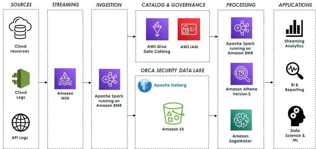
Orca’s data lake is based on open-source technologies that seamlessly integrate with Apache Iceberg. The system ingests data from various sources such as cloud resources, cloud activity logs, and API access logs, and processes billions of messages, resulting in terabytes of data daily. This data is sent to Apache Kafka, which is hosted on Amazon Managed Streaming for Apache Kafka (Amazon MSK). It is then processed using Apache Spark Structured Streaming running on Amazon EMR and stored in the data lake. Amazon EMR streamlines the process of loading all required Iceberg packages and dependencies, ensuring that the data is stored in Apache Iceberg format and ready for consumption as quickly as possible.

The data lake is built on top of Amazon S3 using Apache Iceberg table format with Apache Parquet as the underlying file format. In addition, the AWS Glue Data Catalog enables data discovery, and AWS Identity and Access Management (IAM) enforces secure access controls for the lake and its operations.

The data lake serves as the foundation for a variety of capabilities that are supported by different engines.

Data pipelines built on Apache Spark and Athena SQL analyze and process the data stored in the data lake. These data pipelines generate valuable insights and curated data that are stored in Apache Iceberg tables for downstream usage. This data is then used by various applications for streaming analytics, business intelligence, and reporting.

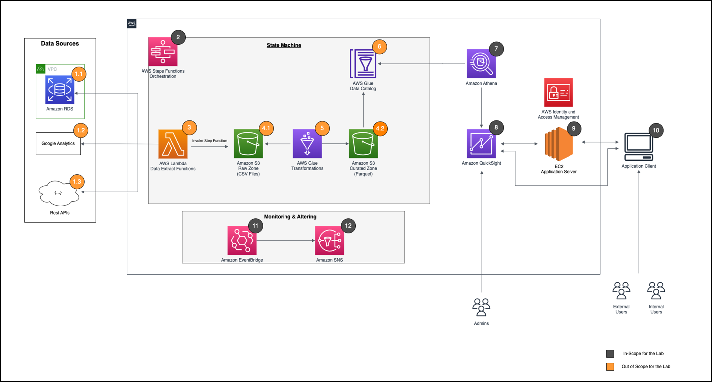
Amazon SageMaker is used to build, train, and deploy a range of ML models. Specifically, the system uses Amazon SageMaker Processing jobs to process the data stored in the data lake, employing the AWS SDK for Pandas (previously known as AWS Wrangler) for various data transformation operations, including cleaning, normalization, and feature engineering. This ensures that the data is suitable for training purposes. Additionally, SageMaker training jobs are employed for training the models. After the models are trained, they are deployed and used to identify anomalies and alert customers in real time to potential security threats. The following diagram illustrates the solution architecture.

Orca security Data Lake Architecture

Challenges and lessons learned

Orca faced several challenges while building its petabyte-scale data lake, including:

  • Determining optimal table partitioning
  • Optimizing EMR streaming ingestion for high throughput
  • Taming the small files problem for fast reads
  • Maximizing performance with Athena version 3
  • Maintaining Apache Iceberg tables
  • Managing data retention
  • Monitoring the data lake infrastructure and operations
  • Mitigating data quality issues

In this section, we describe each of these challenges and the solutions implemented to address them.

Determining optimal table partitioning

Determining optimal partitioning for each table is very important in order to optimize query performance and minimize the impact on teams querying the tables when partitioning changes. Apache Iceberg’s hidden partitions combined with partition transformations proved to be valuable in achieving this goal because it allowed for transparent changes to partitioning without impacting end-users. Additionally, partition evolution enables experimentation with various partitioning strategies to optimize cost and performance without requiring a rewrite of the table’s data every time.

For example, with these features, Orca was able to easily change several of its table partitioning from DAY to HOUR with no impact on user queries. Without this native Iceberg capability, they would have needed to coordinate the new schema with all the teams that query the tables and rewrite the entire data, which would have been a costly, time-consuming, and error-prone process.

Optimizing EMR streaming ingestion for high throughput

As mentioned previously, the system ingests billions of messages daily, resulting in terabytes of data processed and stored each day. Therefore, optimizing the EMR clusters for this type of load while maintaining high throughput and low costs has been an ongoing challenge. Orca addressed this in several ways.

First, Orca chose to use instance fleets with its EMR clusters because they allow optimized resource allocation by combining different instance types and sizes. Instance fleets improve resilience by allowing multiple Availability Zones to be configured. As a result, the cluster will launch in an Availability Zone with all the required instance types, preventing capacity limitations. Additionally, instance fleets can use both Amazon Elastic Compute Cloud (Amazon EC2) On-Demand and Spot instances, resulting in cost savings.

The process of sizing the cluster for high throughput and lower costs involved adjusting the number of core and task nodes, selecting suitable instance types, and fine-tuning CPU and memory configurations. Ultimately, Orca was able to find an optimal configuration consisting of on-demand core nodes and spot task nodes of varying sizes, which provided high throughput but also ensured compliance with SLAs.

Orca also found that using different Kafka Spark Structured Streaming properties, such as minOffsetsPerTrigger, maxOffsetsPerTrigger, and minPartitions, provided higher throughput and better control of the load. Using minPartitions, which enables better parallelism and distribution across a larger number of tasks, was particularly useful for consuming high lags quickly.

Lastly, when dealing with a high data ingestion rate, Amazon S3 may throttle the requests and return 503 errors. To address this scenario, Iceberg offers a table property called write.object-storage.enabled, which incorporates a hash prefix into the stored S3 object path. This approach effectively mitigates throttling problems.

Taming the small files problem for fast reads

A common challenge often encountered when ingesting streaming data into the data lake is the creation of many small files. This can have a negative impact on read performance when querying the data with Athena or Apache Spark. Having a high number of files leads to longer query planning and runtimes due to the need to process and read each file, resulting in overhead for file system operations and network communication. Additionally, this can result in higher costs due to the large number of S3 PUT and GET requests required.

To address this challenge, Apache Spark Structured Streaming provides the trigger mechanism, which can be used to tune the rate at which data is committed to Apache Iceberg tables. The commit rate has a direct impact on the number of files being produced. For instance, a higher commit rate, corresponding to a shorter time interval, results in lots of data files being produced.

In certain cases, launching the Spark cluster on an hourly basis and configuring the trigger to AvailableNow facilitated the processing of larger data batches and reduced the number of small files created. Although this approach led to cost savings, it did involve a trade-off of reduced data freshness. However, this trade-off was deemed acceptable for specific use cases.

In addition, to address preexisting small files within the data lake, Apache Iceberg offers a data files compaction operation that combines these smaller files into larger ones. Running this operation on a schedule is highly recommended to optimize the number and size of the files. Compaction also proves valuable in handling late-arriving data and enables the integration of this data into consolidated files.

Maximizing performance with Athena version 3

Orca was an early adopter of Athena version 3, Amazon’s implementation of the Trino query engine, which provides extensive support for Apache Iceberg. Whenever possible, Orca preferred using Athena over Apache Spark for data processing. This preference was driven by the simplicity and serverless architecture of Athena, which led to reduced costs and easier usage, unlike Spark, which typically required provisioning and managing a dedicated cluster at higher costs.

In addition, Orca used Athena as part of its model training and as the primary engine for ad hoc exploratory queries conducted by data scientists, business analysts, and engineers. However, for maintaining Iceberg tables and updating table properties, Apache Spark remained the more scalable and feature-rich option.

Maintaining Apache Iceberg tables

Ensuring optimal query performance and minimizing storage overhead became a significant challenge as the data lake grew to a petabyte scale. To address this challenge, Apache Iceberg offers several maintenance procedures, such as the following:

  • Data files compaction – This operation, as mentioned earlier, involves combining smaller files into larger ones and reorganizing the data within them. This operation not only reduces the number of files but also enables data sorting based on different columns or clustering similar data using z-ordering. Using Apache Iceberg’s compaction results in significant performance improvements, especially for large tables, making a noticeable difference in query performance between compacted and uncompacted data.
  • Expiring old snapshots – This operation provides a way to remove outdated snapshots and their associated data files, enabling Orca to maintain low storage costs.

Running these maintenance procedures efficiently and cost-effectively using Apache Spark, particularly the compaction operation, which operates on terabytes of data daily, requires careful consideration. This entails appropriately sizing the Spark cluster running on EMR and adjusting various settings such as CPU and memory.

In addition, using Apache Iceberg’s metadata tables proved to be very helpful in identifying issues related to the physical layout of Iceberg’s tables, which can directly impact query performance. Metadata tables offer insights into the physical data storage layout of the tables and offer the convenience of querying them with Athena version 3. By accessing the metadata tables, crucial information about tables’ data files, manifests, history, partitions, snapshots, and more can be obtained, which aids in understanding and optimizing the table’s data layout.

For instance, the following queries can uncover valuable information about the underlying data:

  • The number of files and their average size per partition:
    >SELECT partition, file_count, (total_size / file_count) AS avg_file_size FROM "db"."table$partitions"

  • The number of data files pointed to by each manifest:
    SELECT path, added_data_files_count + existing_data_files_count AS number_of_data_files FROM "db"."table$manifests"

  • Information about the data files:
    SELECT file_path, file_size_in_bytes FROM "db"."table$files"

  • Information related to data completeness:
    SELECT record_count, partition FROM "db"."table$partitions"

Managing data retention

Effective management of data retention in a petabyte-scale data lake is crucial to ensure low storage costs as well as to comply with GDPR. However, implementing such a process can be challenging when dealing with Iceberg data stored in S3 buckets, because deleting files based on simple S3 lifecycle policies could potentially cause table corruption. This is because Iceberg’s data files are referenced in manifest files, so any changes to data files must also be reflected in the manifests.

To address this challenge, certain considerations must be taken into account while handling data retention properly. Apache Iceberg provides two modes for handling deletes, namely copy-on-write (CoW), and merge-on-read (MoR). In CoW mode, Iceberg rewrites data files at the time of deletion and creates new data files, whereas in MoR mode, instead of rewriting the data files, a delete file is written that lists the position of deleted records in files. These files are then reconciled with the remaining data during read time.

In favor of faster read times, CoW mode is preferable and when used in conjunction with the expiring old snapshots operation, it allows for the hard deletion of data files that have exceeded the set retention period.

In addition, by storing the data sorted based on the field that will be utilized for deletion (for example, organizationID), it’s possible to reduce the number of files that require rewriting. This optimization significantly enhances the efficiency of the deletion process, resulting in improved deletion times.

Monitoring the data lake infrastructure and operations

Managing a data lake infrastructure is challenging due to the various components it encompasses, including those responsible for data ingestion, storage, processing, and querying.

Effective monitoring of all these components involves tracking resource utilization, data ingestion rates, query runtimes, and various other performance-related metrics, and is essential for maintaining optimal performance and detecting issues as soon as possible.

Monitoring Amazon EMR was crucial because it played a vital role in the system for data ingestion, processing, and maintenance. Orca monitored the cluster status and resource usage of Amazon EMR by utilizing the available metrics through Amazon CloudWatch. Furthermore, it used JMX Exporter and Prometheus to scrape specific Apache Spark metrics and create custom metrics to further improve the pipelines’ observability.

Another challenge emerged when attempting to further monitor the ingestion progress through Kafka lag. Although Kafka lag tracking is the standard method for monitoring ingestion progress, it posed a challenge because Spark Structured Streaming manages its offsets internally and doesn’t commit them back to Kafka. To overcome this, Orca utilized the progress of the Spark Structured Streaming Query Listener (StreamingQueryListener) to monitor the processed offsets, which were then committed to a dedicated Kafka consumer group for lag monitoring.

In addition, to ensure optimal query performance and identify potential performance issues, it was essential to monitor Athena queries. Orca addressed this by using key metrics from Athena and the AWS SDK for Pandas, specifically TotalExecutionTime and ProcessedBytes. These metrics helped identify any degradation in query performance and keep track of costs, which were based on the size of the data scanned.

Mitigating data quality issues

Apache Iceberg’s capabilities and overall architecture played a key role in mitigating data quality challenges.

One of the ways Apache Iceberg addresses these challenges is through its schema evolution capability, which enables users to modify or add columns to a table’s schema without rewriting the entire data. This feature prevents data quality issues that may arise due to schema changes, because the table’s schema is managed as part of the manifest files, ensuring safe changes.

Furthermore, Apache Iceberg’s time travel feature provides the ability to review a table’s history and roll back to a previous snapshot. This functionality has proven to be extremely useful in identifying potential data quality issues and swiftly resolving them by reverting to a previous state with known data integrity.

These robust capabilities ensure that data within the data lake remains accurate, consistent, and reliable.

Conclusion

Data lakes are an essential part of a modern data architecture, and now it’s easier than ever to create a robust, transactional, cost-effective, and high-performant data lake by using Apache Iceberg, Amazon S3, and AWS Analytics services such as Amazon EMR and Athena.

Since building the data lake, Orca has observed significant improvements. The data lake infrastructure has allowed Orca’s platform to have seamless scalability while reducing the cost of running its data pipelines by over 50% utilizing Amazon EMR. Additionally, query costs were reduced by more than 50% using the efficient querying capabilities of Apache Iceberg and Athena version 3.

Most importantly, the data lake has made a profound impact on Orca’s platform and continues to play a key role in its success, supporting new use cases such as change data capture (CDC) and others, and enabling the development of cutting-edge cloud security solutions.

If Orca’s journey has sparked your interest and you are considering implementing a similar solution in your organization, here are some strategic steps to consider:

  • Start by thoroughly understanding your organization’s data needs and how this solution can address them.
  • Reach out to experts, who can provide you with guidance based on their own experiences. Consider engaging in seminars, workshops, or online forums that discuss these technologies. The following resources are recommended for getting started:
  • An important part of this journey would be to implement a proof of concept. This hands-on experience will provide valuable insights into the complexities of a transactional data lake.

Embarking on a journey to a transactional data lake using Amazon S3, Apache Iceberg, and AWS Analytics can vastly improve your organization’s data infrastructure, enabling advanced analytics and machine learning, and unlocking insights that drive innovation.


About the Authors

Eliad Gat is a Big Data & AI/ML Architect at Orca Security. He has over 15 years of experience designing and building large-scale cloud-native distributed systems, specializing in big data, analytics, AI, and machine learning.

Oded Lifshiz is a Principal Software Engineer at Orca Security. He enjoys combining his passion for delivering innovative, data-driven solutions with his expertise in designing and building large-scale machine learning pipelines.

Yonatan Dolan is a Principal Analytics Specialist at Amazon Web Services. He is located in Israel and helps customers harness AWS analytical services to leverage data, gain insights, and derive value. Yonatan also leads the Apache Iceberg Israel community.

Carlos Rodrigues is a Big Data Specialist Solutions Architect at Amazon Web Services. He helps customers worldwide build transactional data lakes on AWS using open table formats like Apache Hudi and Apache Iceberg.

Sofia Zilberman is a Sr. Analytics Specialist Solutions Architect at Amazon Web Services. She has a track record of 15 years of creating large-scale, distributed processing systems. She remains passionate about big data technologies and architecture trends, and is constantly on the lookout for functional and technological innovations.

Reimagine Software Development With CodeWhisperer as Your AI Coding Companion

Post Syndicated from Danilo Poccia original https://aws.amazon.com/blogs/aws/reimagine-software-development-with-codewhisperer-as-your-ai-coding-companion/

In the few months since Amazon CodeWhisperer became generally available, many customers have used it to simplify and streamline the way they develop software. CodeWhisperer uses generative AI powered by a foundational model to understand the semantics and context of your code and provide relevant and useful suggestions. It can help build applications faster and more securely, and it can help at different levels, from small suggestions to writing full functions and unit tests that help decompose a complex problem into simpler tasks.

Imagine you want to improve your code test coverage or implement a fine-grained authorization model for your application. As you begin writing your code, CodeWhisperer is there, working alongside you. It understands your comments and existing code, providing real-time suggestions that can range from snippets to entire functions or classes. This immediate assistance adapts to your flow, reducing the need for context-switching to search for solutions or syntax tips. Using a code companion can enhance focus and productivity during the development process.

When you encounter an unfamiliar API, CodeWhisperer accelerates your work by offering relevant code suggestions. In addition, CodeWhisperer offers a comprehensive code scanning feature that can detect elusive vulnerabilities and provide suggestions to rectify them. This aligns with best practices such as those outlined by the Open Worldwide Application Security Project (OWASP). This makes coding not just more efficient, but also more secure and with an increased assurance in the quality of your work.

CodeWhisperer can also flag code suggestions that resemble open-source training data, and flag and remove problematic code that might be considered biased or unfair. It provides you with the associated open-source project’s repository URL and license, making it easier for you to review them and add attribution where necessary.

Here are a few examples of CodeWhisperer in action that span different areas of software development, from prototyping and onboarding to data analytics and permissions management.

CodeWhisperer Speeds Up Prototyping and Onboarding
One customer using CodeWhisperer in an interesting way is BUILDSTR, a consultancy that provides cloud engineering services focused on platform development and modernization. They use Node.js and Python in the backend and mainly React in the frontend.

I talked with Kyle Hines, co-founder of BUILDSTR, who said, “leveraging CodeWhisperer across different types of development projects for different customers, we’ve seen a huge impact in prototyping. For example, we are impressed by how quickly we are able to create templates for AWS Lambda functions interacting with other AWS services such as Amazon DynamoDB.” Kyle said their prototyping now takes 40% less time, and they noticed a reduction of more than 50% in the number of vulnerabilities present in customer environments.

Screenshot of a code editor using CodeWhisperer to generate the handler of an AWS Lambda function.

Kyle added, “Because hiring and developing new talent is a perpetual process for consultancies, we leveraged CodeWhisperer for onboarding new developers and it helps BUILDSTR Academy reduce the time and complexity for onboarding by more than 20%.”

CodeWhisperer for Exploratory Data Analysis
Wendy Wong is a business performance analyst building data pipelines at Service NSW and agile projects in AI. For her contributions to the community, she’s also an AWS Data Hero. She says Amazon CodeWhisperer has significantly accelerated her exploratory data analysis process, when she is analyzing a dataset to get a summary of its main characteristics using statistics and visualization tools.

She finds CodeWhisperer to be a swift, user-friendly, and dependable coding companion that accurately infers her intent with each line of code she crafts, and ultimately aids in the enhancement of her code quality through its best practice suggestions.

“Using CodeWhisperer, building code feels so much easier when I don’t have to remember every detail as it will accurately autocomplete my code and comments,” she shared. “Earlier, it would take me 15 minutes to set up data preparation pre-processing tasks, but now I’m ready to go in 5 minutes.”

Screenshot of exploratory data analysis using Amazon CodeWhisperer in a Jupyter notebook.

Wendy says she has gained efficiency by delegating these repetitive tasks to CodeWhisperer, and she wrote a series of articles to explain how to use it to simplify exploratory data analysis.

Another tool used to explore data sets is SQL. Wendy is looking into how CodeWhisperer can help data engineers who are not SQL experts. For instance, she noticed they can just ask to “write multiple joins” or “write a subquery” to quickly get the correct syntax to use.

Asking Amazon CodeWhisperer to generate SQL syntax and code.

CodeWhisperer Accelerates Testing and Other Daily Tasks
I had the opportunity to spend some time with software engineers in the AWS Developer Relations Platform team. That’s the team that, among other things, builds and operates the community.aws website.

Screenshot of the community.aws website, built and operated by the AWS Developer Relations Platform team with some help from Amazon CodeWhisperer.

Nikitha Tejpal’s work primarily revolves around TypeScript, and CodeWhisperer aids her coding process by offering effective autocomplete suggestions that come up as she types. She said she specifically likes the way CodeWhisperer helps with unit tests.

“I can now focus on writing the positive tests, and then use a comment to have CodeWhisperer suggest negative tests for the same code,” she says. “In this way, I can write unit tests in 40% less time.”

Her colleague, Carlos Aller Estévez, relies on CodeWhisperer’s autocomplete feature to provide him with suggestions for a line or two to supplement his existing code, which he accepts or ignores based on his own discretion. Other times, he proactively leverages the predictive abilities of CodeWhisperer to write code for him. “If I want explicitly to get CodeWhisperer to code for me, I write a method signature with a comment describing what I want, and I wait for the autocomplete,” he explained.

For instance, when Carlos’s objective was to check if a user had permissions on a given path or any of its parent paths, CodeWhisperer provided a neat solution for part of the problem based on Carlos’s method signature and comment. The generated code checks the parent directories of a given resource, then creates a list of all possible parent paths. Carlos then implemented a simple permission check over each path to complete the implementation.

“CodeWhisperer helps with algorithms and implementation details so that I have more time to think about the big picture, such as business requirements, and create better solutions,” he added.

Code generated by CodeWhisperer based on method signature and comment.

CodeWhisperer is a Multilingual Team Player
CodeWhisperer is polyglot, supporting code generation for 15 programming languages: Python, Java, JavaScript, TypeScript, C#, Go, Rust, PHP, Ruby, Kotlin, C, C++, Shell scripting, SQL, and Scala.

CodeWhisperer is also a team player. In addition to Visual Studio (VS) Code and the JetBrains family of IDEs (including IntelliJ, PyCharm, GoLand, CLion, PhpStorm, RubyMine, Rider, WebStorm, and DataGrip), CodeWhisperer is also available for JupyterLab, in AWS Cloud9, in the AWS Lambda console, and in Amazon SageMaker Studio.

At AWS, we are committed to helping our customers transform responsible AI from theory into practice by investing to build new services to meet the needs of our customers and make it easier for them to identify and mitigate bias, improve explainability, and help keep data private and secure.

You can use Amazon CodeWhisperer for free in the Individual Tier. See CodeWhisperer pricing for more information. To get started, follow these steps.

Danilo

How quirion created nested email templates using Amazon Simple Email Service (SES)

Post Syndicated from Dominik Richter original https://aws.amazon.com/blogs/messaging-and-targeting/how-quirion-created-nested-email-templates-using-amazon-simple-email-service-ses/

This is part two of the two-part guest series on extending Simple Email Services with advanced functionality. Find part one here.

quirion, founded in 2013, is an award-winning German robo-advisor with more than 1 billion Euro under management. At quirion, we send out five thousand emails a day to more than 60,000 customers.

Managing many email templates can be challenging

We chose Amazon Simple Email Service (SES) because it is an easy-to-use and cost-effective email platform. In particular, we benefit from email templates in SES, which ensure a consistent look and feel of our communication. These templates come with a styled and personalized HTML email body, perfect for transactional emails. However, managing many email templates can be challenging. Several templates share common elements, such as the company’s logo, name or imprint. Over time, some of these elements may change. If they are not updated across all templates, the result is an inconsistent set of templates. To overcome this problem, we created an application to extend the SES template functionality with an interface for creating and managing nested templates.

This post shows how you can implement this solution using Amazon Simple Storage Service (Amazon S3), Amazon API Gateway, AWS Lambda and Amazon DynamoDB.

Solution: compose email from nested templates using AWS Lambda

The solution we built is fully serverless, which means we do not have to manage the underlying infrastructure. We use AWS Cloud Development Kit (AWS CDK) to deploy the architecture.

The figure below describes the architecture diagram for the proposed solution.

  1. The entry point to the application is an API Gateway that routes requests to a Lambda function. A request consists of an HTML file that represents a part of an email template and metadata that describes the structure of the template.
  2. The Lambda function is the key component of the application. It takes the HTML file and the metadata and stores them in a S3 Bucket and a DynamoDB table.
  3. Depending on the metadata, it takes an existing template from storage, inserts the HTML from the request into it and creates a SES email template.

Architecture diagram of the solution: new templates in Amazon SES are created by a Lambda function accessed through API Gateway. THe Lambda function reads and writes HTML from S3 and reads and writes metadata from DynamoDB.

The solution is simplified for this blog post and is used to show the possibilities of SES. We will not discuss the code of the Lambda function as there are several ways to implement it depending on your preferred programming language.

Prerequisites

Walkthrough

Step 1: Use the AWS CDK to deploy the application
To download and deploy the application run the following commands:

$ git clone https://github.com/quirionit/aws-ses-examples.git
$ cd aws-ses-examples/projects/go-src
$ go mod tidy
$ cd ../../projects/template-api
$ npm install
$ cdk deploy

Step 2: Create nested email templates

To create a nested email template, complete the following steps:

  1. On the AWS Console, choose the API Gateway.
  2. You should see an API with a name that includes SesTemplateApi.
    Console screenshot displaying the SesTemplateApi
  3. Click on the name and note the Invoke URL from the details page.

    AWS console showing the invoke URL of the API

  4. In your terminal, navigate to aws-ses-examples/projects/template-api/files and run the following command. Note that you must use your gateway’s Invoke URL.
    curl -F [email protected] -F "isWrapper=true" -F "templateName=m-full" -F "child=content" -F "variables=FIRSTNAME" -F "variables=LASTNAME" -F "plain=Hello {{.FIRSTNAME}} {{.LASTNAME}},{{template \"content\" .}}" YOUR INVOKE URL/emails

    The request triggers the Lambda function, which creates a template in DynamoDB and S3. In addition, the Lambda function uses the properties of the request to decide when and how to create a template in SES. With “isWrapper=true” the template is marked as a template that wraps another template and therefore no template is created in SES. “child=content” specifies the entry point for the child template that is used within m-full.html. It also uses FIRSTNAME and LASTNAME as replacement tags for personalization.

  5. In your terminal, run the following command to create a SES email template that uses the template created in step 4 as a wrapper.

Step 3: Analyze the result

  1. On the AWS Console, choose DynamoDB.
  2. From the sidebar, choose Tables.
  3. Select the table with the name that includes SesTemplateTable.
  4. Choose Explore table items. It should now return two new items.
    Screenshot of the DynamoDB console, displaying two items: m-full and order-confirmation.
    The table stores the metadata that describes how to create a SES email template. Creating an email template in SES is initiated when an element’s Child attribute is empty or null. This is the case for the item with the name order-confirmation. It uses the BucketKey attribute to identify the required HTML stored in S3 and the Parent attribute to determine the metadata from the parent template. The Variables attribute is used to describe the placeholders that are used in the template.
  5. On the AWS Console, choose S3.
  6. Select the bucket with the name that starts with ses-email-templates.
  7. Select the template/ folder. It should return two objects.
    Screenshot of the S3 console, displaying two items: m-full and order-confirmation.
    The m-full.html contains the structure and the design of an email template and is used with the order-confirmation.html which contains the content.
  8. On the AWS Console, choose the Amazon Simple Email Service.
  9. From the sidebar, choose Email templates. It should return the following template.
    Screenshot of the SES console, displaying the order confirmation template

Step 4: Send an email with the created template

  1. Open the send-order-confirmation.json file from aws-ses-examples/projects/template-api/files in a text editor.
  2. Set a verified email address as Source and ToAddresses and save the file.
  3. Navigate your terminal to aws-ses-examples/projects/template-api/files and run the following command:
    aws ses send-templated-email --cli-input-json file://send-order-confirmation.json
  4. As a result, you should get an email.

Step 5: Cleaning up

  1. Navigate your terminal to aws-ses-examples/projects/template-api.
  2. Delete all resources with cdk destroy.
  3. Delete the created SES email template with:
    aws ses delete-template --template-name order-confirmation

Next Steps

There are several ways to extend this solution’s functionality, including the ones below:

  • If you send an email that contains invalid personalization content, Amazon SES might accept the message, but won’t be able to deliver it. For this reason, if you plan to send personalized email, you should configure Amazon SES to send Rendering Failure event notifications.
  • The Amazon SES template feature does not support sending attachments, but you can add the functionality yourself. See part one of this blog series for instructions.
  • When you create a new Amazon SES account, by default your emails are sent from IP addresses that are shared with other SES users. You can also use dedicated IP addresses that are reserved for your exclusive use. This gives you complete control over your sender reputation and enables you to isolate your reputation for different segments within email programs.

Conclusion

In this blog post, we explored how to use Amazon SES with email templates to easily create complex transactional emails. The AWS CLI was used to trigger SES to send an email, but that could easily be replaced by other AWS services like Step Functions. This solution as a whole is a fully serverless architecture where we don’t have to manage the underlying infrastructure. We used the AWS CDK to deploy a predefined architecture and analyzed the deployed resources.

About the authors

Mark Kirchner is a backend engineer at quirion AG. He uses AWS CDK and several AWS services to provide a cloud backend for a web application used for financial services. He follows a full serverless approach and enjoys resolving problems with AWS.
Dominik Richter is a Solutions Architect at Amazon Web Services. He primarily works with financial services customers in Germany and particularly enjoys Serverless technology, which he also uses for his own mobile apps.

The content and opinions in this post are those of the third-party author and AWS is not responsible for the content or accuracy of this post.

How quirion sends attachments using email templates with Amazon Simple Email Service (SES)

Post Syndicated from Dominik Richter original https://aws.amazon.com/blogs/messaging-and-targeting/how-quirion-sends-attachments-using-email-templates-with-amazon-simple-email-service-ses/

This is part one of the two-part guest series on extending Simple Email Services with advanced functionality. Find part two here.

quirion is an award-winning German robo-advisor, founded in 2013, and with more than 1 billion euros under management. At quirion, we send out five thousand emails a day to more than 60,000 customers.

We chose Amazon Simple Email Service (SES) because it is an easy-to-use and cost-effective email platform. In particular, we benefit from email templates in SES, which ensure a consistent look and feel of our communication. These templates come with a styled and personalized HTML email body, perfect for transactional emails. Sometimes it is necessary to add attachments to an email, which is currently not supported by the SES template feature. To overcome this problem, we created a solution to use the SES template functionality and add file attachments.

This post shows how you can implement this solution using Amazon Simple Storage Service (Amazon S3), Amazon EventBridge, AWS Lambda and AWS Step Functions.

Solution: orchestrate different email sending options using AWS Step Functions

The solution we built is fully serverless, which means we do not have to manage the underlying infrastructure. We use AWS Cloud Development Kit (AWS CDK) to deploy the architecture and analyze the resources.

The solution extends SES to send attachments using email templates. SES offers three possibilities for sending emails:

  • Simple  — A standard email message. When you create this type of message, you specify the sender, the recipient, and the message body, and Amazon SES assembles the message for you.
  • Raw — A raw, MIME-formatted email message. When you send this type of email, you have to specify all of the message headers, as well as the message body. You can use this message type to send messages that contain attachments. The message that you specify has to be a valid MIME message.
  • Templated — A message that contains personalization tags. When you send this type of email, Amazon SES API v2 automatically replaces the tags with values that you specify.

In this post, we will combine the Raw and the Templated options.

The figure below describes the architecture diagram for the proposed solution.

  1. The entry point to the application is an EventBridge event bus that routes incoming events to a Step Function workflow.
  2. An event consists of the personalization parameters, the sender and recipient addresses, the template name and optionally the document-related properties such as a reference to the S3 bucket in which the document is stored. Depending on whether the event contains document-related properties, the Step Function workflow decides how the email is prepared and sent.
  3. In case the event does not contain document-related properties, it uses the SendEmail action to send a templated email. The action requires the template name and the data to replace the personalization tags.
  4. If the event contains document-related properties, the raw sending option of the SendEmail action must be used. If we also want to use an email template, we need to use that as a raw MIME message. So, we use the TestRenderEmailTemplate action to get the raw MIME message from the template and use a Lambda function to get and add the document. The Lambda function then triggers SES to send the email.

The solution is simplified for this blog post and is used to show the possibilities of SES. We will not discuss the code of the lambda function as there are several ways to implement it depending on your preferred programming language.

Architecture diagram of the solution: an AWS Step Functions workflow is triggered by EventBridge. If the event contains no document, the workflow triggers Amazon SES SendEmail. Otherwise, it uses SES TestRenderEmailTemplate as input for a Lambda function, which gets the document from S3 and then sends the email.

Prerequisites

Walkthrough

Step 1: Use the AWS CDK to deploy the application

To download and deploy the application run the following commands:

$ git clone [email protected]:quirionit/aws-ses-examples.git
$ cd aws-ses-examples/projects/go-src
$ go mod tidy
$ cd ../../projects/email-sender
$ npm install
$ cdk deploy

Step 2: Create a SES email template

In your terminal, navigate to aws-ses-examples/projects/email-sender and run:

aws ses create-template --cli-input-json file://files/hello_doc.json

Step 3: Upload a sample document to S3

To upload a document to S3, complete the following steps:

  1. On the AWS Console, choose the S3.
  2. Select the bucket with the name that starts with ses-documents.
  3. Copy and save the bucket name for later.
  4. Create a new folder called test.
  5. Upload the hello.txt from aws-ses-examples/projects/email-sender/files into the folder.

Screenshot of Amazon S3 console, showing the ses-documents bucket containing the file tes/hello.txt

Step 4: Trigger sending an email using Amazon EventBridge

To trigger sending an email, complete the following steps:

  1. On the AWS Console, choose the Amazon EventBridge.
  2. Select Event busses from the sidebar.
  3. Select Send events.
  4. Create an event as the following image shows. You can copy the Event detail from aws-ses-examples/projects/email-sender/files/event.json. Don’t forget to replace the sender, recipient and bucket with your values.
    Screenshot of EventBridge console, showing how the sample event with attachment is sent.
  5. As a result of sending the event, you should receive an email with the document attached.
  6. To send an email without attachment, edit the event as follows:
    Screenshot of EventBridge console, showing how the sample event without attachment is sent.

Step 5: Analyze the result

  1. On the AWS Console, choose Step Functions.
  2. Select the state machine with the name that includes EmailSender.
  3. You should see two Succeeded executions. If you select them the dataflows should look like this:
    Screenshot of Step Functions console, showing the two successful invocations.
  4. You can select each step of the dataflows and analyze the inputs and outputs.

Step 6: Cleaning up

  1. Navigate your terminal to aws-ses-examples/projects/email-sender.
  2. Delete all resources with cdk destroy.
  3. Delete the created SES email template with:

aws ses delete-template --template-name HelloDocument

Next Steps

There are several ways to extend this solution’s functionality, see some of them below:

  • If you send an email that contains invalid personalization content, Amazon SES might accept the message, but won’t be able to deliver it. For this reason, if you plan to send personalized email, you should configure Amazon SES to send Rendering Failure event notifications.
  • You can create nested templates to share common elements, such as the company’s logo, name or imprint. See part two of this blog series for instructions.
  • When you create a new Amazon SES account, by default your emails are sent from IP addresses that are shared with other SES users. You can also use dedicated IP addresses that are reserved for your exclusive use. This gives you complete control over your sender reputation and enables you to isolate your reputation for different segments within email programs.

Conclusion

In this blog post, we explored how to use Amazon SES to send attachments using email templates. We used an Amazon EventBridge to trigger a Step Function that chooses between sending a raw or templated SES email. This solution uses a full serverless architecture without having to manage the underlying infrastructure. We used the AWS CDK to deploy a predefined architecture and analyzed the deployed resources.

About the authors

Mark Kirchner is a backend engineer at quirion AG. He uses AWS CDK and several AWS services to provide a cloud backend for a web application used for financial services. He follows a full serverless approach and enjoys resolving problems with AWS.
Dominik Richter is a Solutions Architect at Amazon Web Services. He primarily works with financial services customers in Germany and particularly enjoys Serverless technology, which he also uses for his own mobile apps.

The content and opinions in this post are those of the third-party author and AWS is not responsible for the content or accuracy of this post.

Optimize AWS Config for AWS Security Hub to effectively manage your cloud security posture

Post Syndicated from Nicholas Jaeger original https://aws.amazon.com/blogs/security/optimize-aws-config-for-aws-security-hub-to-effectively-manage-your-cloud-security-posture/

AWS Security Hub is a cloud security posture management service that performs security best practice checks, aggregates security findings from Amazon Web Services (AWS) and third-party security services, and enables automated remediation. Most of the checks Security Hub performs on AWS resources happen as soon as there is a configuration change, giving you nearly immediate visibility of non-compliant resources in your environment, compared to checks that run on a periodic basis. This near real-time finding and reporting of non-compliant resources helps you to quickly respond to infrastructure misconfigurations and reduce risk. Security Hub offers these continuous security checks through its integration with the AWS Config configuration recorder.

By default, AWS Config enables recording for more than 300 resource types in your account. Today, Security Hub has controls that cover approximately 60 of those resource types. If you’re using AWS Config only for Security Hub, you can optimize the configuration of the configuration recorder to track only the resources you need, helping to reduce the costs related to monitoring those resources in AWS Config and the amount of data produced, stored, and analyzed by AWS Config. This blog post walks you through how to set up and optimize the AWS Config recorder when it is used for controls in Security Hub.

Using AWS Config and Security Hub for continuous security checks

When you enable Security Hub, you’re alerted to first enable resource recording in AWS Config, as shown in Figure 1. AWS Config continually assesses, audits, and evaluates the configurations and relationships of your resources on AWS, on premises, and in other cloud environments. Security Hub uses this capability to perform change-initiated security checks. Security Hub checks that use periodic rules don’t depend on the AWS Config recorder. You must enable AWS Config resource recording for all the accounts and in all AWS Regions where you plan to enable Security Hub standards and controls. AWS Config charges for the configuration items that are recorded, separately from Security Hub.

Figure 1: Security Hub alerts you to first enable resource recording in AWS Config

Figure 1: Security Hub alerts you to first enable resource recording in AWS Config

When you get started with AWS Config, you’re prompted to set up the configuration recorder, as shown in Figure 2. AWS Config uses the configuration recorder to detect changes in your resource configurations and capture these changes as configuration items. Using the AWS Config configuration recorder not only allows for continuous security checks, it also minimizes the need to query for the configurations of the individual services, saving your service API quotas for other use cases. By default, the configuration recorder records the supported resources in the Region where the recorder is running.

Note: While AWS Config supports the configuration recording of more than 300 resource types, some Regions support only a subset of those resource types. To learn more, see Supported Resource Types and Resource Coverage by Region Availability.

Figure 2: Default AWS Config settings

Figure 2: Default AWS Config settings

Optimizing AWS Config for Security Hub

Recording global resources as well as current and future resources in AWS Config is more than what is necessary to enable Security Hub controls. If you’re using the configuration recorder only for Security Hub controls, and you want to cost optimize your use of AWS Config or reduce the amount of data produced, stored, and analyzed by AWS Config, you only need to record the configurations of approximately 60 resource types, as described in AWS Config resources required to generate control findings.

Set up AWS Config, optimized for Security Hub

We’ve created an AWS CloudFormation template that you can use to set up AWS Config to record only what’s needed for Security Hub. You can download the template from GitHub.

This template can be used in any Region that supports AWS Config (see AWS Services by Region). Although resource coverage varies by Region (Resource Coverage by Region Availability), you can still use this template in every Region. If a resource type is supported by AWS Config in at least one Region, you can enable the recording of that resource type in all Regions supported by AWS Config. For the Regions that don’t support the specified resource type, the recorder will be enabled but will not record any configuration items until AWS Config supports the resource type in the Region.

Security Hub regularly releases new controls that might rely on recording additional resource types in AWS Config. When you use this template, you can subscribe to Security Hub announcements with Amazon Simple Notification Service (SNS) to get information about newly released controls that might require you to update the resource types recorded by AWS Config (and listed in the CloudFormation template). The CloudFormation template receives periodic updates in GitHub, but you should validate that it’s up to date before using it. You can also use AWS CloudFormation StackSets to deploy, update, or delete the template across multiple accounts and Regions with a single operation. If you don’t enable the recording of all resources in AWS Config, the Security Hub control, Config.1 AWS Config should be enabled, will fail. If you take this approach, you have the option to disable the Config.1 Security Hub control or suppress its findings using the automation rules feature in Security Hub.

Customizing for your use cases

You can modify the CloudFormation template depending on your use cases for AWS Config and Security Hub. If your use case for AWS Config extends beyond your use of Security Hub controls, consider what additional resource types you will need to record the configurations of for your use case. For example, AWS Firewall Manager, AWS Backup, AWS Control Tower, AWS Marketplace, and AWS Trusted Advisor require AWS Config recording. Additionally, if you use other features of AWS Config, such as custom rules that depend on recording specific resource types, you can add these resource types in the CloudFormation script. You can see the results of AWS Config rule evaluations as findings in Security Hub.

Another customization example is related to the AWS Config configuration timeline. By default, resources evaluated by Security Hub controls include links to the associated AWS Config rule and configuration timeline in AWS Config for that resource, as shown in Figure 3.

Figure 3: Link from Security Hub control to the configuration timeline for the resource in AWS Config

Figure 3: Link from Security Hub control to the configuration timeline for the resource in AWS Config

The AWS Config configuration timeline, as illustrated in Figure 4, shows you the history of compliance changes for the resource, but it requires the AWS::Config::ResourceCompliance resource type to be recorded. If you need to track changes in compliance for resources and use the configuration timeline in AWS Config, you must add the AWS::Config::ResourceCompliance resource type to the CloudFormation template provided in the preceding section. In this case, Security Hub may change the compliance of the Security Hub managed AWS Config rules, which are recorded as configuration items for the AWS::Config::ResourceCompliance resource type, incurring additional AWS Config recorder charges.

Figure 4: Config resource timeline

Figure 4: Config resource timeline

Summary

You can use the CloudFormation template provided in this post to optimize the AWS Config configuration recorder for Security Hub to reduce your AWS Config costs and to reduce the amount of data produced, stored, and analyzed by AWS Config. Alternatively, you can run AWS Config with the default settings or use the AWS Config console or scripts to further customize your configuration to fit your use case. Visit Getting started with AWS Security Hub to learn more about managing your security alerts.

 
If you have feedback about this post, submit comments in the Comments section below. If you have questions about this post, contact AWS Support.

Want more AWS Security news? Follow us on Twitter.

Nicholas Jaeger

Nicholas Jaeger

Nicholas is a Senior Security Specialist Solutions Architect at AWS. His background includes software engineering, teaching, solutions architecture, and AWS security. Today, he focuses on helping as many customers operate as securely as possible on AWS. Nicholas also hosts AWS Security Activation Days to provide customers with prescriptive guidance while using AWS security services to increase visibility and reduce risk.

Dora Karali

Dora Karali

Dora is a Senior Manager of Product Management at AWS External Security Services. She is currently responsible for Security Hub and has previously worked on GuardDuty, too. Dora has more than 15 years of experience in cybersecurity. She has defined strategy for and created, managed, positioned, and sold cybersecurity cloud and on-premises products and services in multiple enterprise and consumer markets.

How Amazon Finance Automation built a data mesh to support distributed data ownership and centralize governance

Post Syndicated from Nitin Arora original https://aws.amazon.com/blogs/big-data/how-amazon-finance-automation-built-a-data-mesh-to-support-distributed-data-ownership-and-centralize-governance/

Amazon Finance Automation (FinAuto) is the tech organization of Amazon Finance Operations (FinOps). Its mission is to enable FinOps to support the growth and expansion of Amazon businesses. It works as a force multiplier through automation and self-service, while providing accurate and on-time payments and collections. FinAuto has a unique position to look across FinOps and provide solutions that help satisfy multiple use cases with accurate, consistent, and governed delivery of data and related services.

In this post, we discuss how the Amazon Finance Automation team used AWS Lake Formation and the AWS Glue Data Catalog to build a data mesh architecture that simplified data governance at scale and provided seamless data access for analytics, AI, and machine learning (ML) use cases.

Challenges

Amazon businesses have grown over the years. In the early days, financial transactions could be stored and processed on a single relational database. In today’s business world, however, even a subset of the financial space dedicated to entities such as Accounts Payable (AP) and Accounts Receivable (AR) requires separate systems handling terabytes of data per day. Within FinOps, we can curate more than 300 datasets and consume many more raw datasets from dozens of systems. These datasets can then be used to power front end systems, ML pipelines, and data engineering teams.

This exponential growth necessitated a data landscape that was geared towards keeping FinOps operating. However, as we added more transactional systems, data started to grow in operational data stores. Data copies were common, with duplicate pipelines creating redundant and often out-of-sync domain datasets. Multiple curated data assets were available with similar attributes. To resolve these challenges, FinAuto decided to build a data services layer based on a data mesh architecture. FinAuto wanted to verify that the data domain owners would retain ownership of their datasets while users got access to the data by using a data mesh architecture.

Solution overview

Being customer focused, we started by understanding our data producers’ and consumers’ needs and priorities. Consumers prioritized data discoverability, fast data access, low latency, and high accuracy of data. Producers prioritized ownership, governance, access management, and reuse of their datasets. These inputs reinforced the need of a unified data strategy across the FinOps teams. We decided to build a scalable data management product that is based on the best practices of modern data architecture. Our source system and domain teams were mapped as data producers, and they would have ownership of the datasets. FinAuto provided the data services’ tools and controls necessary to enable data owners to apply data classification, access permissions, and usage policies. It was necessary for domain owners to continue this responsibility because they had visibility to the business rules or classifications and applied that to the dataset. This enabled producers to publish data products that were curated and authoritative assets for their domain. For example, the AR team created and governed their cash application dataset in their AWS account AWS Glue Data Catalog.

With many such partners building their data products, we needed a way to centralize data discovery, access management, and vending of these data products. So we built a global data catalog in a central governance account based on the AWS Glue Data Catalog. The FinAuto team built AWS Cloud Development Kit (AWS CDK), AWS CloudFormation, and API tools to maintain a metadata store that ingests from domain owner catalogs into the global catalog. This global catalog captures new or updated partitions from the data producer AWS Glue Data Catalogs. The global catalog is also periodically fully refreshed to resolve issues during metadata sync processes to maintain resiliency. With this structure in place, we then needed to add governance and access management. We selected AWS Lake Formation in our central governance account to help secure the data catalog, and added secure vending mechanisms around it. We also built a front-end discovery and access control application where consumers can browse datasets and request access. When a consumer requests access, the application validates the request and routes them to a respective producer via internal tickets for approval. Only after the data producer approves the request are permissions provisioned in the central governance account through Lake Formation.

Solution tenets

A data mesh architecture has its own advantages and challenges. By democratizing the data product creation, we removed dependencies on a central team. We made reuse of data possible with data discoverability and minimized data duplicates. This also helped remove data movement pipelines, thereby reducing data transfer and maintenance costs.

We realized, however, that our implementation could potentially impact day-to-day tasks and inhibit adoption. For example, data producers need to onboard their dataset to the global catalog, and complete their permissions management before they can share that with consumers. To overcome this obstacle, we prioritized self-service tools and automation with a reliable and simple-to-use interface. We made interaction, including producer-consumer onboarding, data access request, approvals, and governance, quicker through the self-service tools in our application.

Solution architecture

Within Amazon, we isolate different teams and business processes with separate AWS accounts. From a security perspective, the account boundary is one of the strongest security boundaries in AWS. Because of this, the global catalog resides in its own locked-down AWS account.

The following diagram shows AWS account boundaries for producers, consumers, and the central catalog. It also describes the steps involved for data producers to register their datasets as well as how data consumers get access. Most of these steps are automated through convenience scripts with both AWS CDK and CloudFormation templates for our producers and consumer to use.

Solution Architecture Diagram

The workflow contains the following steps:

  1. Data is saved by the producer in their own Amazon Simple Storage Service (Amazon S3) buckets.
  2. Data source locations hosted by the producer are created within the producer’s AWS Glue Data Catalog.
  3. Data source locations are registered with Lake Formation.
  4. An onboarding AWS CDK script creates a role for the central catalog to use to read metadata and generate the tables in the global catalog.
  5. The metadata sync is set up to continuously sync data schema and partition updates to the central data catalog.
  6. When a consumer requests table access from the central data catalog, the producer grants Lake Formation permissions to the consumer account AWS Identity and Access Management (IAM) role and tables are visible in the consumer account.
  7. The consumer account accepts the AWS Resource Access Manager (AWS RAM) share and creates resource links in Lake Formation.
  8. The consumer data lake admin provides grants to IAM users and roles mapping to data consumers within the account.

The global catalog

The basic building block of our business-focused solutions are data products. A data product is a single domain attribute that a business understands as accurate, current, and available. This could be a dataset (a table) representing a business attribute like a global AR invoice, invoice aging, aggregated invoices by a line of business, or a current ledger balance. These attributes are calculated by the domain team and are available for consumers who need that attribute, without duplicating pipelines to recreate it. Data products, along with raw datasets, reside within their data owner’s AWS account. Data producers register their data catalog’s metadata to the central catalog. We have services to review source catalogs to identify and recommend classification of sensitive data columns such as name, email address, customer ID, and bank account numbers. Producers can review and accept those recommendations, which results in corresponding tags applied to the columns.

Producer experience

Producers onboard their accounts when they want to publish a data product. Our job is to sync the metadata between the AWS Glue Data Catalog in the producer account with the central catalog account, and register the Amazon S3 data location with Lake Formation. Producers and data owners can use Lake Formation for fine-grained access controls on the table. It is also now searchable and discoverable via the central catalog application.

Consumer experience

When a data consumer discovers the data product that they’re interested in, they submit a data access request from the application UI. Internally, we route the request to the data owner for the disposition of the request (approval or rejection). We then create an internal ticket to track the request for auditing and traceability. If the data owner approves the request, we run automation to create an AWS RAM resource share to share with the consumer account covering the AWS Glue database and tables approved for access. These consumers can now query the datasets using the AWS analytics services of their choice like Amazon Redshift Spectrum, Amazon Athena, and Amazon EMR.

Operational excellence

Along with building the data mesh, it’s also important to verify that we can operate with efficiency and reliability. We recognize that the metadata sync process is at the heart of this global data catalog. As such, we are hypervigilant of this process and have built alarms, notifications, and dashboards to verify that this process doesn’t fail silently and create a single point of failure for the global data catalog. We also have a backup repair service that syncs the metadata from producer catalogs into the central governance account catalog periodically. This is a self-healing mechanism to maintain reliability and resiliency.

Empowering customers with the data mesh

The FinAuto data mesh hosts around 850 discoverable and shareable datasets from multiple partner accounts. There are more than 300 curated data products to which producers can provide access and apply governance with fine-grained access controls. Our consumers use AWS analytics services such as Redshift Spectrum, Athena, Amazon EMR, and Amazon QuickSight to access their data. This capability with standardized data vending from the data mesh, along with self-serve capabilities, allows you to innovate faster without dependency on technical teams. You can now get access to data faster with automation that continuously improves the process.

By serving the FinOps team’s data needs with high availability and security, we enabled them to effectively support operation and reporting. Data science teams can now use the data mesh for their finance-related AI/ML use cases such as fraud detection, credit risk modeling, and account grouping. Our finance operations analysts are now enabled to dive deep into their customer issues, which is most important to them.

Conclusion

FinOps implemented a data mesh architecture with Lake Formation to improve data governance with fine-grained access controls. With these improvements, the FinOps team is now able to innovate faster with access to the right data at the right time in a self-serve manner to drive business outcomes. The FinOps team will continue to innovate in this space with AWS services to further provide for customer needs.

To learn more about how to use Lake Formation to build a data mesh architecture, see Design a data mesh architecture using AWS Lake Formation and AWS Glue.


About the Authors

Nitin Arora PicNitin Arora is a Sr. Software Development Manager for Finance Automation in Amazon. He has over 18 years of experience building business critical, scalable, high-performance software. Nitin leads several data and analytics initiatives within Finance, which includes building Data Mesh. In his spare time, he enjoys listening to music and read.

Pradeep Misra PicPradeep Misra is a Specialist Solutions Architect at AWS. He works across Amazon to architect and design modern distributed analytics and AI/ML platform solutions. He is passionate about solving customer challenges using data, analytics, and AI/ML. Outside of work, Pradeep likes exploring new places, trying new cuisines, and playing board games with his family. He also likes doing science experiments with his daughters.

Rajesh Rao PicRajesh Rao is a Sr. Technical Program Manager in Amazon Finance. He works with Data Services teams within Amazon to build and deliver data processing and data analytics solutions for Financial Operations teams. He is passionate about delivering innovative and optimal solutions using AWS to enable data-driven business outcomes for his customers.

Andrew Long PicAndrew Long, the lead developer for data mesh, has designed and built many of the big data processing systems that have fueled Amazon’s financial data processing infrastructure. His work encompasses a range of areas, including S3-based table formats for Spark, diverse Spark performance optimizations, distributed orchestration engines and the development of data cataloging systems. Additionally, Andrew finds pleasure in sharing his knowledge of partner acrobatics.

Satyen GauravKumar Satyen Gaurav, is an experienced Software Development Manager at Amazon, with over 16 years of expertise in big data analytics and software development. He leads a team of engineers to build products and services using AWS big data technologies, for providing key business insights for Amazon Finance Operations across diverse business verticals. Beyond work, he finds joy in reading, traveling and learning strategic challenges of chess.

How AWS helped Altron Group accelerate their vision for optimized customer engagement

Post Syndicated from Jason Yung original https://aws.amazon.com/blogs/big-data/how-aws-helped-altron-group-accelerate-their-vision-for-optimized-customer-engagement/

This is a guest post co-authored by Jacques Steyn, Senior Manager Professional Services at Altron Group.

Altron is a pioneer of providing data-driven solutions for their customers by combining technical expertise with in-depth customer understanding to provide highly differentiated technology solutions. Alongside their partner AWS, they participated in AWS Data-Driven Everything (D2E) workshops and a bespoke AWS Immersion Day workshop that catered to their needs to improve their engagement with their customers.

This post discusses the journey that took Altron from their initial goals, to technical implementation, to the business value created from understanding their customers and their unique opportunities better. They were able to think big but start small with a working solution involving rich business intelligence (BI) and insights provided to their key business areas.

Data-Driven Everything engagement

Altron has provided information technology services since 1965 across South Africa, the Middle East, and Australia. Although the group saw strong results at 2022-year end, the region continues to experience challenging operating conditions with global supply chains disrupted, electronic component shortages, and scarcity of IT talent.

To reflect the needs of their customers spread across different geographies and industries, Altron has organized their operating model across individual Operating Companies (OpCos). These are run autonomously with different sales teams, creating siloed operations and engagement with customers and making it difficult to have a holistic and unified sales motion.

To succeed further, their vision of data requires it to be accessible and actionable to all, with key roles and responsibilities defined by those who produce and consume data, as shown in the following figure. This allows for transparency, speed to action, and collaboration across the group while enabling the platform team to evangelize the use of data:

Altron engaged with AWS to seek advice on their data strategy and cloud modernization to bring their vision to fruition. The D2E program was selected to help identify the best way to think big but start small by working collaboratively to ideate on the opportunities to build data as a product, particularly focused on federating customer profile data in an agile and scalable approach.

Amazon mechanisms such as Working Backwards were employed to devise the most delightful and meaningful solution and put customers at the heart of the experience. The workshop helped devise the think big solution that starting with the Systems Integration (SI) OpCo as the first flywheel turn would be the best way to start small and prototype the initial data foundation collaboratively with AWS Solutions Architects.

Preparing for an AWS Immersion Day workshop

The typical preparation of an AWS Immersion Day involves identifying examples of common use case patterns and utilizing demonstration data. To maximize its success, the Immersion Day was stretched across multiple days as a hands-on workshop to enable Altron to bring their own data, build a robust data pipeline, and scale their long-term architecture. In addition, AWS and Altron identified and resolved any external dependencies, such as network connectivity to data sources and targets, where Altron was able to put the connectivity to the sources in place.

Identifying key use cases

After a number of preparation meetings to discuss business and technical aspects of the use case, AWS and Altron identified two uses cases to resolve their two business challenges:

  • Business intelligence for business-to-business accounts – Altron wanted to focus on their business-to-business (B2B) accounts and customer data. In particular, they wanted to enable their account managers, sales executives, and analysts to use actual data and facts to get a 360 view of their accounts.
    • Goals – Grow revenue, increase the conversion ratio of opportunities, reduce the average sales cycle, improve the customer renewal rate.
    • Target – Dashboards to be refreshed on a daily basis that would provide insights on sales, gross profit, sales pipelines, and customers.
  • Data quality for account and customer data – Altron wanted to enable data quality and data governance best practices.
    • Goals – Lay the foundation for a data platform that can be used in the future by internal and external stakeholders.

Conducting the Immersion Day workshop

Altron set aside 4 days for their Immersion Day, during which time AWS had assigned a dedicated Solutions Architect to work alongside them to build the following prototype architecture:

This solution includes the following components:

  1. AWS Glue is a serverless data integration service that makes it simple to discover, prepare, move, and integrate data from multiple sources for analytics, machine learning, and application development. The Altron team created an AWS Glue crawler and configured it to run against Azure SQL to discover its tables. The AWS Glue crawler populates the table definition with its schema in AWS Glue Data Catalog.
  2. This step consists of two components:
    1. A set of AWS Glue PySpark jobs reads the source tables from Azure SQL and outputs the resulting data in the Amazon Simple Storage Service “Raw Zone”. Basic formatting and readability of the data is standardized here. The jobs run on a scheduled basis, according to the upstream data availability (which currently is daily).
    2. Users are able to manually upload reference files (CSV and Excel format) via the Amazon Web Services console directly to the Amazon S3 buckets. Depending on the frequency of upload, the Altron team will consider automated mechanisms and remove manual upload.
  3. The reporting zone is based on a set of Amazon Athena views, which are consumed for BI purposes. The Altron team used Athena to explore the source tables and create the views in SQL language. Depending on the needs, the Altron team will materialize these views or create corresponding AWS Glue jobs.
  4. Athena exposes the content of the reporting zone for consumption.
  5. The content of the reporting zone is ingested via SPICE in Amazon QuickSight. BI users create dashboards and reports in QuickSight. Business users can access QuickSight dashboards from their mobile, thanks to the QuickSight native application, configured to use single sign-on (SSO).
  6. An AWS Step Functions state machine orchestrates the run of the AWS Glue jobs. The Altron team will expand the state machine to include automated refresh of QuickSight SPICE datasets.
  7. To verify the data quality of the sources through statistically-relevant metrics, AWS Glue Data Quality runs data quality tasks on relevant AWS Glue tables. This can be run manually or scheduled via Amazon Eventbridge (Optional).

Generating business outcomes

In 4 days, the Altron SI team left the Immersion Day workshop with the following:

  • A data pipeline ingesting data from 21 sources (SQL tables and files) and combining them into three mastered and harmonized views that are cataloged for Altron’s B2B accounts.
  • A set of QuickSight dashboards to be consumed via browser and mobile.
  • Foundations for a data lake with data governance controls and data quality checks. The datasets used for the workshop originate from different systems; by integrating the datasets during the workshop implementation, the Altron team can have a comprehensive overview of their customers.

Altron’s sales teams are now able to quickly refresh dashboards encompassing previously disparate datasets that are now centralized to get insights about sales pipelines and forecasts on their desktop or mobile. The technical teams are equally adept at adjusting to business needs by autonomously onboarding new data sources and further enriching the user experience and trust in the data.

Conclusion

In this post, we walked you through the journey the Altron team took with AWS. The outcomes to identify the opportunities that were most pressing to Altron, applying a working backward approach and coming up with a best-fit architecture, led to the subsequent AWS Immersion Day to implement a working prototype that helped them become more data-driven.

With their new focus on AWS skills and mechanisms, increasing trust in their internal data, and understanding the importance of driving change in data literacy and mindset, Altron is better set up for success to best serve their customers in the region.

To find out more about how Altron and AWS can help work backward on your data strategy and employ the agile methodologies discussed in this post, check out Data Management. To learn more about how can help you turn your ideas into solutions, visit the D2E website and the series of AWS Immersion Days that you can choose from. For more hands-on bespoke options, contact your AWS Account Manager, who can provide more details.

Special thanks to everyone at Altron Group who helped contribute to the success of the D2E and Build Lab workshops:

  • The Analysts (Liesl Kok, Carmen Kotze)
  • Data Engineers (Banele Ngemntu, James Owen, Andrew Corry, Thembelani Mdlankomo)
  • QuickSight BI Developers (Ricardo De Gavino Dias, Simei Antoniades)
  • Cloud Administrator (Shamiel Galant)

About the authors

Jacques Steyn runs the Altron Data Analytics Professional Services. He has been leading the building of data warehouses and analytic solutions for the past 20 years. In his free time, he spends time with his family, whether it be on the golf , walking in the mountains, or camping in South Africa, Botswana, and Namibia.

Jason Yung is a Principal Analytics Specialist with Amazon Web Services. Working with Senior Executives across the Europe and Asia-Pacific Regions, he helps customers become data-driven by understanding their use cases and articulating business value through Amazon mechanisms. In his free time, he spends time looking after a very active 1-year-old daughter, alongside juggling geeky activities with respectable hobbies such as cooking sub-par food.

Michele Lamarca is a Senior Solutions Architect with Amazon Web Services. He helps architect and run Solutions Accelerators in Europe to enable customers to become hands-on with AWS services and build prototypes quickly to release the value of data in the organization. In his free time, he reads books and tries (hopelessly) to improve his jazz piano skills.

Hamza is a Specialist Solutions Architect with Amazon Web Services. He runs Solutions Accelerators in EMEA regions to help customers accelerate their journey to move from an idea into a solution in production. In his free time, he spends time with his family, meets with friends, swims in the municipal swimming pool, and learns new skills.

Vega Cloud brings FinOps solutions to their customers faster by embedding Amazon QuickSight

Post Syndicated from Kris Bliesner original https://aws.amazon.com/blogs/big-data/vega-cloud-brings-finops-solutions-to-their-customers-faster-by-embedding-amazon-quicksight/

This is a guest post authored by Kris Bliesner and Mike Brown from Vega Cloud.

Vega Cloud is a premier member of the FinOps Foundation, a program by Linux Foundation supporting FinOps practitioners on cloud financial management best practices. Vega Cloud provides a place where finance, engineers, and innovators come together to accelerate the business value of the cloud with concrete curated data, context-relevant recommendations, and automation to achieve cost savings. Vega Cloud’s platform is based on the FinOps Foundation’s best practices and removes the confusion behind the business value of cloud services and accelerates strategic decisions while maintaining cost optimization. Vega’s curated reports provide actionable insights to accelerate time-to-value from years into days. On average, Vega’s customers immediately identify 15–25% of underutilized cloud spend with a clear direction on how to reallocate the funds to maximize business impact.

Vega Cloud has been growing rapidly and saw an opportunity to accelerate cloud intelligence at hyperscale. Engineering leadership chose Amazon QuickSight, which allowed Vega to add insightful analytics into its platform with customized interactive visuals and dashboards, while scaling at a lower cost without the need to manage infrastructure.

In this post, we discuss how Vega uses QuickSight to bring cloud intelligence solutions to our customers.

Bringing solutions to market at a fast pace

The Vega Cloud Platform was designed from the start by cloud pioneers to enable businesses to get the most value out of their cloud spend. This is done by a multi-step process that starts with data analytics and ends with automation to remediate inefficiencies. The Vega Cloud Platform consumes customer billing and usage information from cloud providers and third parties, and uses that data to show customers what they are spending and which services they are consuming, with business context to help the customer with chargebacks and cost inquiries. The Vega Cloud Platform then analyzes the data collected and produces context relevant recommendations across five major categories: financial, waste elimination, utilization, process, and architecture. Finally, the Vega Cloud Platform enables customers to choose which recommendations to implement through automated processes and immediately receive cost benefits without massive amounts of work by end developers or app teams.

Vega is constantly updating and improving the platform by adding more recommendation types, deeper analytics, and easier automation to save time. When looking for an embedded analytics solution to bring these insights to customers, Vega looked for a tool that would allow us to keep up with our rapid growth and iterate quickly. With QuickSight, Vega has been able to scale from the proof of concept stage to enterprise-level analytics and visualizations as the company grows. QuickSight enables our product team to ship product quickly and rapidly test customer feedback and assumptions. Vega has tremendously reduced the time from idea to implementation for the analytics solutions by using QuickSight.

Using embedded QuickSight saved Vega 6–12 months of development time, allowing us to go to market sooner. Vega Cloud’s team of certified FinOps practitioners—a unique combination of finance professionals, architects, FinOps practitioners, educators, engineers, financial analysts, and data analysts with deep expertise in multi-cloud environments—can focus on driving business growth and meeting customer needs. QuickSight gives the Vega team one place to build reports and dashboards, allowing the Vega Cloud Platform to deliver data analytics to customers quickly and consistently. The Vega Cloud Platform uses QuickSight APIs to seamlessly onboard new users. In addition to the cost savings Vega Cloud has achieved by saving development time, QuickSight doesn’t require licensing or maintenance costs. The AWS pay-as-you-go pricing model allowed Vega Cloud to hit the ground running and scale with real-time demand.

Creating a powerful array of solutions for customers

By embedding QuickSight, Vega Cloud has been able to bring a wealth of information to cloud consumers, helping them gain value and efficiencies. For example, an enterprise customer in the energy industry engaged Vega for cloud cost optimization and saw monthly savings exceeding 25% with cumulative savings of over $1.36 million over 11 months. They moved from 24% Reserved Instance/Savings Plans (RI/SP) coverage to 53% coverage. Their optimization efforts led them to increase their cloud commit by 10 times over 5 years.

The Vega Cloud Platform has two SKUs that use embedded QuickSight: Vega Inform and Vega Optimize. Vega Inform is about cost allocation, chargebacks and showbacks, anomaly detection, spend analysis, and deep usage analytics. Vega Optimize is an easy-to-use set of dashboards to help customers better understand the optimization opportunities they have across their entire enterprise. In the Vega Inform SKU, the Vega Cloud Platform provides true multi-cloud cost reporting with cash and fiscal views and the ability to switch between them seamlessly. The Vega Cloud Platform is a curated data platform to ensure customers avoid garbage in/garbage out scenarios. Vega curates customer usage and billing data to verify billing rates, usage, and credit allocation, and then enables retroactive cleanups to historical spend.

Vega Optimize is a core piece of the Vega Cloud Platform and allows end-users to see cost-optimization recommendations with business context added using the embedded QuickSight dashboards. The Vega Cloud Platform enables end-users to self-manage and approve optimization recommendations for implementation—ensuring that businesses are taking the actions they need to better manage their cloud investments.

Vega customers can identify and act upon near-term optimization opportunities prioritized by business impact and level of effort, as well as identify, purchase, and track committed use resources. QuickSight enables end-users to easily filter down data to exactly what the user wants to see. Doing so enables questions to be answered more quickly, which ensures the right optimization takes place in a timely manner. The depth and breadth of data the Vega Cloud Platform consumes and surfaces to end-users via QuickSight provides customers with a platform approach to enabling FinOps within their organizations.

Powerful and dynamic QuickSight features

The Vega Cloud Platform ingests billions of lines of data on behalf of customers, which must be converted into actionable insight and personalized to a decision-maker’s role inside the organization. Processing terabytes of data can lead to delayed and infrequent reports, slowing down an organization’s ability to respond and compete in their respective markets. It is paramount that customers have consistent, dependable access to timely reports with the correct business context. QuickSight is powered by SPICE (Super-fast, Parallel, In-memory Calculation Engine), a robust in-memory engine that now supports up to 1 billion rows of data. Thanks to the Vega Cloud Platform’s implementation of QuickSight, Vega has offloaded the responsibility including engineering from customers to ingest and curate billions of rows of data every day. The Vega Cloud Platform uses role-based permissions, with row-level security from QuickSight, to centralize and tailor data to prioritize actionable insights with the ability to quickly investigate details to provide evidence-based decisions to customers.

QuickSight allows Vega to highlight data that is considered high-cost or high-value to its customers so that they can take quick action. This is accomplished by purpose-built dashboards based on over a decade of experience to ensure customers see the items that will be most impactful in their optimization efforts. The advanced visualizations, sorting, and filtering capabilities of QuickSight allow the Vega Cloud Platform to scale usage by multiple groups within a business, including finance, DevOps, IT and many others. Along with QuickSight, the Vega Cloud Platform uses many other AWS services, including but not limited to Amazon Relational Database Service (Amazon RDS), Amazon Redshift, Amazon Athena, AWS Glue, and more.

Scaling into the future with QuickSight

Vega is focused on continuing to provide customers with cloud intelligence at hyperscale using QuickSight. The Vega Cloud Platform roadmap includes a proof of concept for Amazon QuickSight Q, which would give customers the ability to ask questions in natural language and receive accurate answers with relevant visualizations that help users gain insights from the data. This also includes paginated reports, which makes it easier for customers to create, schedule, and share reports.

QuickSight has enabled Vega Cloud to grow rapidly, while saving time and money and delivering FinOps solutions to businesses in any and every vertical industry consuming cloud at scale.

To learn more about how you can embed customized data visuals and interactive dashboards into any application, visit Amazon QuickSight Embedded.


About the Authors

Kris Bliesner, CEO, Vega Cloud is a seasoned technology leader with over 25 years of experience in IT management, cloud computing, and consumer-based technology. As the co-founder and CEO of Vega Cloud, Kris continues to be at the forefront of revolutionizing cloud infrastructure optimization.

Mike Brown, CTO, Vega Cloud is a highly-skilled technology leader and co-founder of Vega Cloud, where he currently serves as the Chief Technology Officer (CTO). With a proven track record in driving technological innovation, Mike has been instrumental in shaping the application architecture and solutions for the company.

Amazon Mexico FP&A dives deep into financial data with Amazon QuickSight

Post Syndicated from Gonzalo Lezma original https://aws.amazon.com/blogs/big-data/amazon-mexico-fpa-dives-deep-into-financial-data-with-amazon-quicksight/

This is a guest post by Gonzalo Lezma from Amazon Mexico FP&A.

The Financial Planning and Analysis (FP&A) team in Mexico provides strategic support to Amazon’s CFO and executive team on planning, analysis, and reporting related to Amazon Mexico. We produce and manage key finance deliverables, such as internal profit and loss (P&L) reports for all business groups. We are also involved in planning processes, such as monthly forecast estimates, annual operating plans, and 3-year forecasts.

Our team needed to address five key challenges: manual recurrent reporting, managing data from different sources, moving away from large and slow spreadsheets, enabling ad hoc data insights extraction by business users, and variance analysis. To tackle these issues, we chose Amazon QuickSight for our business intelligence (BI) needs.

In this post, I discuss how QuickSight has enabled us to focus on financial and business analysis that helps drive business strategy.

Fully automating recurrent reporting

Creating and maintaining reports manually is time-consuming due to dense data granularity and multiple business groups and sub-products. This involves a lot of data to process and numerous stakeholders to please. Therefore, recurrent reporting requires allocating human hours to elaborate those reports, check the spreadsheet formulas, and rely on attention to detail to validate the numbers to report.

QuickSight dashboards show the Profit and Loss (P&L), which update as soon as databases refresh, simplifying recurrent reporting dramatically. There is no need for human intervention, which eliminates any risk of error during the elaboration of recurrent reporting. The maintenance and elaboration time has decreased from a week to zero for processes that are currently in QuickSight. We employ the QuickSight alerts feature (as shown in the following screenshot) to remain informed when specific metrics exceed a predefined threshold. This enables us to stay cognizant of significant changes in our P&L at a granular level.

Data from different sources

With new marketplaces and channels constantly emerging in Mexico, not all of them are integrated into the financial planning system; therefore, shadow P&Ls and reports are common and unavoidable. Therefore, the team has to find ways to track them without compromising accuracy or consistency, which poses significant additional challenges. Moreover, with multiple channels and teams reporting those numbers, it’s time-consuming to manually update the data source from every team we work with.

QuickSight can onboard data on channels and products that are relatively new and haven’t been onboarded to official planning systems. The team has numerous options to load data, including Amazon Redshift, CSV files, and Excel spreadsheets. There is virtually no limit on the granularity and scope of our reports.

Large and slow spreadsheets

Although spreadsheets are a popular tool for financial analysis, they have limitations for large and complex datasets. This affects performance, reliability, and validation. Spreadsheets become slow, bulky, and prone to errors, making it challenging to manage large datasets efficiently.

The SPICE (Super-fast, Parallel, In-memory Calculation Engine) in-memory engine that QuickSight uses is unparalleled, compared with other solutions the team tried in the past such as Tableau and Excel, eliminating the need for large spreadsheets dramatically. In addition to the time spent in elaborating the reports, the team was having a hard time reading and visualizing them.

The MX Financial Planning and Analysis Dashboard shown below shows the main contributors to the Gross Merchandise Sales for our business. If sales growth is at 20.92% as it says in the graph, we know that 9.09% is due to our NAFN channel. The graph at the bottom shows which products drove the sales increase.

Ad hoc data insights extraction

The finance space frequently requires ad hoc financial data on recent historic trends for a particular product and timespan. Given the number of channels, products, and scenarios the team works on, this creates a big problem to tackle. Extracting these data insights requires significant bandwidth, which can take away from other essential tasks the team needs to focus on.

Amazon QuickSight Q can answer any simple question about the data in a straightforward and nimble manner, allowing the team to handle ad hoc data insights using natural language requests. The following screenshot shows a graph we frequently get using Q to report shipping costs.

Variance analysis

Providing accurate and insightful variance analysis is a significant challenge for anyone working in financial analysis (for example, explaining price or profit per unit by separating mix effect and rate effect). Huge and difficult-to-understand spreadsheets might sound familiar to anyone who has tried to tackle this problem in the finance space.

With QuickSight URL actions (as shown in the following gif and screenshot), the team can right-click on the variance they want to dissect and link to another sheet with granular detail that has a decomposition of the main drivers explaining that particular variance, replacing the huge and cumbersome Excel variance analysis tool the team used to have.

Summary

All in all, the dynamic and interactive nature of the dashboards allows our internal users to go deeper into the data with just a click of the mouse. Now, building visualizations is intuitive, insightful, and fast. In fact, the whole solution and tools were built without the need of a dedicated BI team. In addition to this, we developed internal QuickSight dashboards to view our own customers’ QuickSight usage, so we have perfect visibility on which areas and users are more active and which features are more used by our partners.

With our QuickSight solution, we have automation, self-service, speedy reaction to requests, and flexibility.

To learn more about how QuickSight can help your business with dashboards, reports, and more, visit Amazon QuickSight.


About the Author

Gonzalo Lezma is the Mexico Finance Manager for the Amazon LATAM Finance Team. He is a lifelong learner, tech and data lover.

Automated Code Review on Pull Requests using AWS CodeCommit and AWS CodeBuild

Post Syndicated from Verinder Singh original https://aws.amazon.com/blogs/devops/automated-code-review-on-pull-requests-using-aws-codecommit-and-aws-codebuild/

Pull Requests play a critical part in the software development process. They ensure that a developer’s proposed code changes are reviewed by relevant parties before code is merged into the main codebase. This is a standard procedure that is followed across the globe in different organisations today. However, pull requests often require code reviewers to read through a great deal of code and manually check it against quality and security standards. These manual reviews can lead to problematic code being merged into the main codebase if the reviewer overlooks any problems.

To help solve this problem, we recommend using Amazon CodeGuru Reviewer to assist in the review process. CodeGuru Reviewer identifies critical defects and deviation from best practices in your code. It provides recommendations to remediate its findings as comments in your pull requests, helping reviewers miss fewer problems that may have otherwise made into production. You can easily integrate your repositories in AWS CodeCommit with Amazon CodeGuru Reviewer following these steps.

The purpose of this post isn’t, however, to show you CodeGuru Reviewer. Instead, our aim is to help you achieve automated code reviews with your pull requests if you already have a code scanning tool and need to continue using it. In this post, we will show you step-by-step how to add automation to the pull request review process using your code scanning tool with AWS CodeCommit (as source code repository) and AWS CodeBuild (to automatically review code using your code reviewer). After following this guide, you should be able to give developers automatic feedback on their code changes and augment manual code reviews so fewer problems make it into your main codebase.

Solution Overview

The solution comprises of the following components:

  1. AWS CodeCommit: AWS service to host private Git repositories.
  2. Amazon EventBridge: AWS service to receive pullRequestCreated and pullRequestSourceBranchUpdated events and trigger Amazon EventBridge rule.
  3. AWS CodeBuild: AWS service to perform code review and send the result to AWS CodeCommit repository as pull request comment.

The following diagram illustrates the architecture:

Figure 1: This architecture diagram illustrates the workflow where developer raises a Pull Request and receives automated feedback on the code changes using AWS CodeCommit, AWS CodeBuild and Amazon EventBridge rule

Figure 1. Architecture Diagram of the proposed solution in the blog

  1. Developer raises a pull request against the main branch of the source code repository in AWS CodeCommit.
  2. The pullRequestCreated event is received by the default event bus.
  3. The default event bus triggers the Amazon EventBridge rule which is configured to be triggered on pullRequestCreated and pullRequestSourceBranchUpdated events.
  4. The EventBridge rule triggers AWS CodeBuild project.
  5. The AWS CodeBuild project runs the code quality check using customer’s choice of tool and sends the results back to the pull request as comments. Based on the result, the AWS CodeBuild project approves or rejects the pull request automatically.

Walkthrough

The following steps provide a high-level overview of the walkthrough:

  1. Create a source code repository in AWS CodeCommit.
  2. Create and associate an approval rule template.
  3. Create AWS CodeBuild project to run the code quality check and post the result as pull request comment.
  4. Create an Amazon EventBridge rule that reacts to AWS CodeCommit pullRequestCreated and pullRequestSourceBranchUpdated events for the repository created in step 1 and set its target to AWS CodeBuild project created in step 3.
  5. Create a feature branch, add a new file and raise a pull request.
  6. Verify the pull request with the code review feedback in comment section.

1. Create a source code repository in AWS CodeCommit

Create an empty test repository in AWS CodeCommit by following these steps. Once the repository is created you can add files to your repository following these steps. If you create or upload the first file for your repository in the console, a branch is created for you named main. This branch is the default branch for your repository. If you are using a Git client instead, consider configuring your Git client to use main as the name for the initial branch. This blog post assumes the default branch is named as main.

2. Create and associate an approval rule template

Create an AWS CodeCommit approval rule template and associate it with the code repository created in step 1 following these steps.

3. Create AWS CodeBuild project to run the code quality check and post the result as pull request comment

This blog post is based on the assumption that the source code repository has JavaScript code in it, so it uses jshint as a code analysis tool to review the code quality of those files. However, users can choose a different tool as per their use case and choice of programming language.

Create an AWS CodeBuild project from AWS Management Console following these steps and using below configuration:

  • Source: Choose the AWS CodeCommit repository created in step 1 as the source provider.
  • Environment: Select the latest version of AWS managed image with operating system of your choice. Choose New service role option to create the service IAM role with default permissions.
  • Buildspec: Use below build specification. Replace <NODEJS_VERSION> with the latest supported nodejs runtime version for the image selected in previous step. Replace <REPOSITORY_NAME> with the repository name created in step 1. The below spec installs the jshint package, creates a jshint config file with a few sample rules, runs it against the source code in the pull request commit, posts the result as comment to the pull request page and based on the results, approves or rejects the pull request automatically.
version: 0.2
phases:
  install:
    runtime-versions:
      nodejs: <NODEJS_VERSION>
    commands:
      - npm install jshint --global
  build:
    commands:
      - echo \{\"esversion\":6,\"eqeqeq\":true,\"quotmark\":\"single\"\} > .jshintrc
      - CODE_QUALITY_RESULT="$(echo \`\`\`) $(jshint .)"; EXITCODE=$?
      - aws codecommit post-comment-for-pull-request --pull-request-id $PULL_REQUEST_ID --repository-name <REPOSITORY_NAME> --content "$CODE_QUALITY_RESULT" --before-commit-id $DESTINATION_COMMIT_ID --after-commit-id $SOURCE_COMMIT_ID --region $AWS_REGION	
      - |
        if [ $EXITCODE -ne 0 ]
        then
          PR_STATUS='REVOKE'
        else
          PR_STATUS='APPROVE'
        fi
      - REVISION_ID=$(aws codecommit get-pull-request --pull-request-id $PULL_REQUEST_ID | jq -r '.pullRequest.revisionId')
      - aws codecommit update-pull-request-approval-state --pull-request-id $PULL_REQUEST_ID --revision-id $REVISION_ID --approval-state $PR_STATUS --region $AWS_REGION

Once the AWS CodeBuild project has been created successfully, modify its IAM service role by following the below steps:

  • Choose the CodeBuild project’s Build details tab.
  • Choose the Service role link under the Environment section which should navigate you to the CodeBuild’s IAM service role in IAM console.
  • Expand the default customer managed policy and choose Edit.
  • Add the following actions to the existing codecommit actions:
"codecommit:CreatePullRequestApprovalRule",
"codecommit:GetPullRequest",
"codecommit:PostCommentForPullRequest",
"codecommit:UpdatePullRequestApprovalState"

  • Choose Next.
  • On the Review screen, choose Save changes.

4. Create an Amazon EventBridge rule that reacts to AWS CodeCommit pullRequestCreated and pullRequestSourceBranchUpdated events for the repository created in step 1 and set its target to AWS CodeBuild project created in step 3

Follow these steps to create an Amazon EventBridge rule that gets triggered whenever a pull request is created or updated using the following event pattern. Replace the <REGION>, <ACCOUNT_ID> and <REPOSITORY_NAME> placeholders with the actual values. Select target of the event rule as AWS CodeBuild project created in step 3.

Event Pattern

{
    "detail-type": ["CodeCommit Pull Request State Change"],
    "resources": ["arn:aws:codecommit:<REGION>:<ACCOUNT_ID>:<REPOSITORY_NAME>"],
    "source": ["aws.codecommit"],
    "detail": {
      "isMerged": ["False"],
      "pullRequestStatus": ["Open"],
      "repositoryNames": ["<REPOSITORY_NAME>"],
      "destinationReference": ["refs/heads/main"],
      "event": ["pullRequestCreated", "pullRequestSourceBranchUpdated"]
    },
    "account": ["<ACCOUNT_ID>"]
  }

Follow these steps to configure the target input using the below input path and input template.

Input transformer – Input path

{
    "detail-destinationCommit": "$.detail.destinationCommit",
    "detail-pullRequestId": "$.detail.pullRequestId",
    "detail-sourceCommit": "$.detail.sourceCommit"
}

Input transformer – Input template

{
    "sourceVersion": <detail-sourceCommit>,
    "environmentVariablesOverride": [
        {
            "name": "DESTINATION_COMMIT_ID",
            "type": "PLAINTEXT",
            "value": <detail-destinationCommit>
        },
        {
            "name": "SOURCE_COMMIT_ID",
            "type": "PLAINTEXT",
            "value": <detail-sourceCommit>
        },
        {
            "name": "PULL_REQUEST_ID",
            "type": "PLAINTEXT",
            "value": <detail-pullRequestId>
        }
    ]
}

5. Create a feature branch, add a new file and raise a pull request

Create a feature branch following these steps. Push a new file called “index.js” to the root of the repository with the below content.

function greet(dayofweek) {
  if (dayofweek == "Saturday" || dayofweek == "Sunday") {
    console.log("Have a great weekend");
  } else {
    console.log("Have a great day at work");
  }
}

Now raise a pull request using the feature branch as source and main branch as destination following these steps.

6. Verify the pull request with the code review feedback in comment section

As soon as the pull request is created, the AWS CodeBuild project created in step 3 above will be triggered which will run the code quality check and post the results as a pull request comment. Navigate to the AWS CodeCommit repository pull request page in AWS Management Console and check under the Activity tab to confirm the automated code review result being displayed as the latest comment.

The pull request comment submitted by AWS CodeBuild highlights 6 errors in the JavaScript code. The errors on lines first and third are based on the jshint rule “eqeqeq”. It recommends to use strict equality operator (“===”) instead of the loose equality operator (“==”) to avoid type coercion. The errors on lines second, fourth and fifth are based on jshint rule “quotmark” which recommends to use single quotes with strings instead of double quotes for better readability. These jshint rules are defined in AWS CodeBuild project’s buildspec in step 3 above.

Figure 2: The image shows the AWS CodeCommit pull request's Activity tab with code review results automatically posted by the automated code reviewer

Figure 2. Pull Request comments updated with automated code review results.

Conclusion

In this blog post we’ve shown how using AWS CodeCommit and AWS CodeBuild services customers can automate their pull request review process by utilising Amazon EventBridge events and using their own choice of code quality tool. This simple solution also makes it easier for the human reviewers by providing them with automated code quality results as input and enabling them to focus their code review more on business logic code changes rather than static code quality issues.

About the authors

Blog post's primary author's image

Verinder Singh

Verinder Singh is an experienced Solution’s Architect based out of Sydney, Australia with 16+ years of experience in software development and architecture. He works primarily on building large scale open-source AWS solutions for common customer use cases and business problems. In his spare time, he enjoys vacationing and watching movies with his family.

Blog post's secondary author's image

Deenadayaalan Thirugnanasambandam

Deenadayaalan Thirugnanasambandam is a Principal Cloud Architect at AWS. He provides prescriptive architectural guidance and consulting that enable and accelerate customers’ adoption of AWS.

Validating attestation documents produced by AWS Nitro Enclaves

Post Syndicated from maceneff original https://aws.amazon.com/blogs/compute/validating-attestation-documents-produced-by-aws-nitro-enclaves/

This blog post is written by Paco Gonzalez Senior EMEA IoT Specialist SA.

AWS Nitro Enclaves offers an isolated, hardened, and highly constrained environment to host security-critical applications. Think of AWS Nitro Enclaves as regular Amazon Elastic Compute Cloud (Amazon EC2) virtual machines (VMs) but with the added benefit of the environment being highly constrained.

A great benefit of using AWS Nitro Enclaves is that you can run your software as if it was a regular EC2 instance, but with no persistent storage and limited access to external systems. The only way to communicate with AWS Nitro Enclaves is using a VSOCK socket. This special type of communication mechanism acts as an isolated communication channel between the parent EC2 instance and AWS Nitro Enclaves.Diagram that shows how Nitro Enclaves uses the proven isolation of the Nitro Hypervisor to further isolate the CPU and memory of the Nitro Enclaves from users, applications, and libraries on the parent instance.

 Fig 1 – AWS Nitro Enclaves uses the proven isolation of the Nitro Hypervisor to further isolate the CPU and memory of the Nitro Enclaves from users, applications, and libraries on the parent instance.

AWS Nitro Enclaves comes with a custom Linux device called the Nitro Security Module (NSM), which is accessible via /dev/nsm. This device provides attestation capability to the Nitro Enclaves. The attestation comes in the form of an attestation document. The attestation document makes it easy and safe to build trust between systems that interact with the Nitro Enclaves. The external system must have a mechanism to process the attestation document to determine the validity of the attestation document.

In this post, I go through the anatomy of an attestation document produced by the NSM API. I then show you an example of how to perform different validations that help determine the accuracy of an attestation document produced by the AWS Nitro Enclaves Security Module. I use syntactic and semantic validations to check for the attestation document’s correctness before proceeding with a cryptographic validation of the contents of the document’s payload. The examples used in this post use the C language. Look at the companion repository available in GitHub for access to the all source code used in this post.

Anatomy of an attestation document produced by AWS Nitro Enclaves

The attestation document uses the Concise Binary Object Representation (CBOR) format to encode the data. The CBOR object is wrapped using the CBOR Object Signing and Encryption (COSE) protocol. The COSE format used is a single-signer data structure called “COSE_Sign1”. The object is comprised of headers, the payload, and a signature.

For more information about COSE, see RFC 8152: CBOR Object Signing and Encryption (COSE). For more information about CBOR, see RFC 8949 Concise Binary Object Representation (CBOR).

We published a library to make it easy to interact with the NSM. The library contains helpers which your application, running on the Nitro Enclaves, can use to communicate with the NSM device.

Here is the minimum code needed to generate an attestation document:

#include <stdlib.h>
#include <stdio.h>
#include <nsm.h>

#define NSM_MAX_ATTESTATION_DOC_SIZE (16 * 1024)

int main(void) {

    /// NSM library initialization function.  
    /// *Returns*: A descriptor for the opened device file.

    int nsm_fd = nsm_lib_init();
    if (nsm_fd < 0) {
        exit(1);
    }

    /// NSM `GetAttestationDoc` operation for non-Rust callers.  
    /// *Argument 1 (input)*: The descriptor to the NSM device file.  
    /// *Argument 2 (input)*: User data.  
    /// *Argument 3 (input)*: The size of the user data buffer.  
    /// *Argument 4 (input)*: Nonce data.  
    /// *Argument 5 (input)*: The size of the nonce data buffer.  
    /// *Argument 6 (input)*: Public key data.  
    /// *Argument 7 (input)*: The size of the public key data buffer.  
    /// *Argument 8 (output)*: The obtained attestation document.  
    /// *Argument 9 (input / output)*: The document buffer capacity (as input)
    /// and the size of the received document (as output).  
    /// *Returns*: The status of the operation.

    int status;
    uint8_t att_doc_buff[NSM_MAX_ATTESTATION_DOC_SIZE];
    uint32_t att_doc_cap_and_size = NSM_MAX_ATTESTATION_DOC_SIZE;

    status = nsm_get_attestation_doc(nsm_fd, NULL, 0, NULL, 0, NULL, 0, att_doc_buff, 
                                    &att_doc_cap_and_size);
    if (status != ERROR_CODE_SUCCESS) {
        printf("[Error] Request::Attestation got invalid response: %s\n",status);
        exit(1);
    }

    printf("########## attestation_document_buff ##########\r\n");
    for(int i=0; i<att_doc_cap_and_size; i++)
        fprintf(stdout, "%02X", att_doc_buff[i]);

    exit(0);
}

To produce a sample attestation document, initialize the device, call the function ‘nsm_get_attestation_doc’ inside the AWS Nitro Enclaves, and dump the contents. The library is written using Rust, but it contains
bindings for C. You can read more about the library and some of the other relevant capabilities
here.

The COSE headers contain a protected and an un-protected data section. The cryptographic algorithm used for the signature is specified inside the protected area. AWS Nitro Enclaves use a 384-bit elliptic curve algorithm (P-384) to sign attestation documents. AWS Nitro Enclaves do not use the unprotected data field so it is always left blank.

The payload contains fixed parameters that include the following: information about the issuing NSM, a timestamp of the issuing event, a map of all the locked Platform Configuration Registers (PCRs) at the moment the attestation document was generated, the hashing algorithm used to produce the digest that was used to calculate the PCR values – AWS Nitro Enclaves use a 384 bit secure hashing algorithm (SHA384), a x509 certificate signed by AWS Nitro Enclaves’ Private Public Key Infrastructure (PKI). An AWS Nitro Enclaves certificate expires three hours after it has been issued. The common name (CN) contains information about the issuing NSM – and finally the issuing Certificate Authority (CA) bundle. The payload also contains optional parameters that a third-party application can use to create custom authentication and authorization workflows. The optional parameters are: a public key, a cryptographic nonce, and additional arbitrary data.

Finally, the signature is the result of a signing operation using the private key related to the public key contained inside the certificate that is part of the payload.

Diagram that illustrates the components of a attestation document produced by a Nitro Enclave

Fig 2. An attestation document is generated and signed by the Nitro Hypervisor. It contains information about the Nitro Enclaves and it can be used by an external service to verify the identity of Nitro Enclaves and to establish trust. You can use the attestation document to build your own cryptographic attestation mechanisms.

Syntactical validation

Early validation of the attestation document format makes sure that only documents that conform to the expected structure are processed in subsequent steps.

I start by attempting to decode the CBOR object and testing to see if it corresponds to a COSE object signed with one signer or ‘COSE_Sign1’ structure. This can be easily done by looking at the most significant first three bits (MSB) of the first byte – I am expecting a stream of CBOR bytes (decimal 6). Then, I take the least significant (LSB) remaining five bits of the first byte – I am expecting a tag that tells me it is a COSE_Sign1 object (decimal 18).

assert(att_doc_buff[0*] == 6 <<5 | 18); // 0xD2

* Note that the time of writing, the NSM does not include the COSE tag and thus this validation cannot be made and is mentioned in this post for informational purposes only. However, it is important to keep this in mind, as the tag is part of the standard, and the NSM device or library could include it in the future.*

The next step is to parse the actual CBOR object. A COSE_Sign1 object is an array of size 4 (protected headers, un protected headers, payload, and signature). Therefore, I must check that the next three MSB correspond to Type 4 (array) and that the size is exactly 4.

assert(att_doc_buff[0] == 4 <<5 | 4); // 0x84

The next byte determines what the first CBOR item of the array looks like. I am expecting the protected COSE header as the first item of the array. The CBOR field should indicate that the contents of the item are of a Type 2 (raw bytes) and the size should be exactly 4.

assert(att_doc_buff[1] == 2 <<5 | 4); // 0x44

The next four bytes represent the protected header. The contents of this item is a regular CBOR object. The object should contain a Type 5 (map) with a single item (1). The item first key is expected to be the number 1. The first three MSB of the first byte should be a Type 1 (negative integer). The remaining five LSB should indicate that the value is an 8-bit number (decimal 24). The last byte should be negative 35 as it maps to the P-384 curve that Nitro Enclaves use. Note that CBOR negative numbers are stored minus 1.

assert(att_doc_buff[2] == 5 <<5 | 1); // 0xA1
assert(att_doc_buff[3] == 0x01); // 0x01
assert(att_doc_buff[4] == 1 <<5 | 24); // 0x38
assert(att_doc_buff[4] == 35-1); // 0x22

The next byte corresponds to the unprotected header. AWS Nitro Enclaves do not use unprotected headers. Therefore, the expected is a Type 5 (map) with zero items.

assert(att_doc_buff[6] == 5 <<5 | 0); // 0xA0

Now that I am done inspecting the headers, I can move onto the payload. The CBOR object used for the payload is Type 2 (raw bytes). This time we are expecting a large steam of bytes. The remaining five LSB are used to indicate the data type used to indicate the size of the byte stream (i.e. 8-bit, 16-bit). AWS Nitro Enclaves attestation documents are about 5 KiB without using any of the three optional parameters. The optional parameters have a size limit of 1 KiB each. This means that it would be highly unlikely for the buffer to be larger than a 16-bit number (CBOR short count: 25).

assert(att_doc_buff[8] == 2 <<5 | 25); // 0x59

The next two bytes represent the size of the payload which I am going to skip those for now, as the contents of the payload are validated in subsequent steps. I’ll move onto the final portion of the attestation document: the signature. The signature has to be a Type 2 (raw bytes) of exactly 96 bytes.

    uint16_t payload_size = att_doc_buff[8] << 8 | att_doc_buff[9];
    assert(att_doc_buff[9+payload_size+1] == (2<<5 | 24));   // 0x58
    assert(att_doc_buff[9+payload_size+1+1] == 96);         // 0x60

At this point, I have validated that the data produced by the NSM looks the way it should. My application is ready to start looking into the contents of the attestation document.

I want to make sure that the document contains all mandatory fields and I can check that the fields have the right structure and their sizes are within the expected boundaries. I have evidence that the data looks the way it should, so I am ready to use an off-the-shelf CBOR library to make the validation process easier instead of doing it by hand.

Here is an example of how to load a CBOR object using libcbor and standard C libraries to check the contents. I am showing just one example to illustrate the process. Refer to the section ‘Verifying the root of trust’ in the AWS Nitro Enclaves User Guide for a detailed description of each parameter and the validations that your application should perform to make sure that the document is valid.

#include <stdlib.h>
#include <stdio.h>
#include <string.h>
#include <assert.h>

#include <cbor.h>
#include <openssl/ssl.h>

#define APP_X509_BUFF_LEN                   (1024*2)
#define APP_ATTDOC_BUFF_LEN                 (1024*10)

void output_handler(char * msg){
    fprintf(stdout, "\r\n%s\r\n", msg);
}

void output_handler_bytes(uint8_t * buffer, int buffer_size){    
    for(int i=0; i<buffer_size; i++)
        fprintf(stdout, "%02X", buffer[i]);
    fprintf(stdout, "\r\n");
}

int read_file( unsigned char * file, char * file_name, size_t elements) {
    FILE * fp; size_t file_len = 0;
    fp = fopen(file_name, "r");
    file_len = fread(file, sizeof(char), elements, fp);
    if (ferror(fp) != 0 ) {
        fputs("Error reading file", stderr);
    } 
    fclose(fp);
    return file_len; 
}  

int main(int argc, char* argv[]) {

    // STEP 0 - LOAD ATTESTATION DOCUMENT

    // Check inputs, expect two
    if (argc != 3) { 
        fprintf(stderr, "%s\r\n", "ERROR: usage: ./main {att_doc_sample.bin} {AWS_NitroEnclaves_Root-G1.pem}"); exit(1);
    }

    // Load file into buffer, use 1st argument
    unsigned char * att_doc_buff = malloc(APP_ATTDOC_BUFF_LEN);
    int att_doc_len = read_file(att_doc_buff, argv[1], APP_ATTDOC_BUFF_LEN );

    // STEP 1 - SYTANCTIC VALIDATON

    // Check COSE TAG (skipping - not currently implemented by AWS Nitro Enclaves)
    // assert(att_doc_buff[0] == 6 <<5 | 18); // 0xD2
    // Check if this is an array of exactly 4 items
    assert(att_doc_buff[0] == (4<<5 | 4));      // 0x84
    // Check if next item is a byte stream of 4 bytes
    assert(att_doc_buff[1] == (2<<5 | 4));      // 0x44
    // Check is fist item if byte stream is a map with 1 item
    assert(att_doc_buff[2] == (5<<5 | 1));      // 0xA1
    // Check that the first key of the map is 0x01
    assert(att_doc_buff[3] == 0x01);            // 0x01
    // Check that value of the the first key of the map is -35 (P-384 curve)
    assert(att_doc_buff[4] == (1 <<5 | 24));    // 0x38
    assert(att_doc_buff[5] == 35-1);            // 0x22
    // Check that next item is a map of 0 items
    assert(att_doc_buff[6] == (5<<5 | 0));      // 0xA0
    // Check that the next item is a byte stream and the size is a 16-bit number (dec. 25)
    assert(att_doc_buff[7] == (2<<5 | 25));     // 0x59
    // Cast the 16-bit number
    uint16_t payload_size = att_doc_buff[8] << 8 | att_doc_buff[9];
    // Check that the item after the payload is a byte stream and the size is 8-bit number (dec. 24)
    assert(att_doc_buff[9+payload_size+1] == (2<<5 | 24));   // 0x58
    // Check that the size of the signature is exactly 96 bytes
    assert(att_doc_buff[9+payload_size+1+1] == 96);         // 0x60

    // Parse buffer using library
    struct cbor_load_result ad_result;
    cbor_item_t * ad_item = cbor_load(att_doc_buff, att_doc_len, &ad_result);
    free(att_doc_buff); // not needed anymore

    // Parse protected header -> item 0 
    cbor_item_t * ad_pheader = cbor_array_get(ad_item, 0); 
    size_t ad_pheader_len = cbor_bytestring_length(ad_pheader);

    // Parse signed bytes -> item 2 (skip un-protected headers as they are always empty)
    cbor_item_t * ad_signed = cbor_array_get(ad_item, 2);
    size_t ad_signed_len = cbor_bytestring_length(ad_signed);

    // Load signed bytes as a new CBOR object
    unsigned char * ad_signed_d = cbor_bytestring_handle(ad_signed);
    struct cbor_load_result ad_signed_result;
    cbor_item_t * ad_signed_item = cbor_load(ad_signed_d, ad_signed_len, &ad_signed_result);

    // Create the pair structure
    struct cbor_pair * ad_signed_item_pairs = cbor_map_handle(ad_signed_item);

    // Parse signature -> item 3
    cbor_item_t * ad_sig = cbor_array_get(ad_item, 3); 
    size_t ad_sig_len = cbor_bytestring_length(ad_sig);
    unsigned char * ad_sig_d = cbor_bytestring_handle(ad_sig);

    // Example 01: Check that the first item's key is the string "module_id" and that is not empty
    size_t module_k_len = cbor_string_length(ad_signed_item_pairs[0].key);
    unsigned char * module_k_str = realloc(cbor_string_handle(ad_signed_item_pairs[0].key), module_k_len+1); //null char
    module_k_str[module_k_len] = '\0';
    size_t module_v_len = cbor_string_length(ad_signed_item_pairs[0].value);
    unsigned char * module_v_str = realloc(cbor_string_handle(ad_signed_item_pairs[0].value), module_v_len+1); //null char
    module_v_str[module_v_len] = '\0';
    assert(module_k_len != 0);
    assert(module_v_len != 0);

    // Example 02: Check that the module id key is actually the string "module_id"
    assert(!strcmp("module_id",(const char *)module_k_str));

    // Example 03: Check that the signature is exactly 96 bytes long
    assert(ad_sig_len == 96);

    // Example 04: Check that the protected header is exactly 4 bytes long
    assert(ad_pheader_len == 4);

Semantic validation

The next step is to look at the data contained in the attestation document and check if it conforms to pre-defined business rules. The attestation document contains a certificate that was signed by the AWS Nitro Enclaves’ PKI. This validation it is important, as it proves that the document was signed by the AWS Nitro Enclaves’ PKI.

The signature of an x509 certificate is based on the certificate’s payload digest. Validating this signature means that I trust the information contained within the certificate, including the public key which I can later use to validate the attestation document itself. Furthermore, the information in the document contains details about the NSM module and a timestamp. Passing this check provides the assurances I need to trust that the document originated from my software running on AWS Nitro Enclaves at a specific time.

Diagram that illustrates the components of a x.509 certificate, part of the payload of a attestation document produced by AWS Nitro Enclaves.

Fig 3. The attestation document contains a x.509 certificate that was signed by the AWS Nitro Enclaves’ PKI.

Here is an example of how I use the AWS Nitro Enclaves’ Private PKI root certificate from an external file. Then, use the CA bundle contained in the attestation document to validate the authenticity of the certificate contained in the document. In this example, I am using the OpenSSL library.

// STEP 2 -  SEMANTIC VALIDATION

    // Load AWS Nitro Enclave's Private PKI root certificate
    unsigned char * x509_root_ca = malloc(APP_X509_BUFF_LEN);
    int x509_root_ca_len = read_file(x509_root_ca, argv[2], APP_X509_BUFF_LEN );
    BIO * bio = BIO_new_mem_buf((void*)x509_root_ca, x509_root_ca_len);
    X509 * caX509 = PEM_read_bio_X509(bio, NULL, NULL, NULL);
    if (caX509 == NULL) {
        fprintf(stderr, "%s\r\n", "ERROR: PEM_read_bio_X509 failed"); exit(1);
    }
    free(x509_root_ca); free(bio);
    // Create CA_STORE
    X509_STORE * ca_store = NULL;
    ca_store = X509_STORE_new();
    /* ADD X509_V_FLAG_NO_CHECK_TIME FOR TESTING! TODO REMOVE */
    X509_STORE_set_flags (ca_store, X509_V_FLAG_NO_CHECK_TIME);
    if (X509_STORE_add_cert(ca_store, caX509) != 1) {
        fprintf(stderr, "%s\r\n", "ERROR: X509_STORE_add_cert failed"); exit(1);
    }
    // Add certificates to CA_STORE from cabundle
    // Skip the first one [0] as that is the Root CA and we want to read it from an external source
    for (int i = 1; i < cbor_array_size(ad_signed_item_pairs[5].value); ++i){ 
        cbor_item_t * ad_cabundle = cbor_array_get(ad_signed_item_pairs[5].value, i); 
        size_t ad_cabundle_len = cbor_bytestring_length(ad_cabundle);
        unsigned char * ad_cabundle_d = cbor_bytestring_handle(ad_cabundle);
        X509 * cabnX509 = X509_new();
        cabnX509 = d2i_X509(&cabnX509, (const unsigned char **)&ad_cabundle_d, ad_cabundle_len);
        if (cabnX509 == NULL) {
            fprintf(stderr, "%s\r\n", "ERROR: d2i_X509 failed"); exit(1);
        }
        if (X509_STORE_add_cert(ca_store, cabnX509) != 1) {
            fprintf(stderr, "%s\r\n", "ERROR: X509_STORE_add_cert failed"); exit(1);
        }
    }

    // Load certificate from attestation dcoument - this a certificate that we don't trust (yet)
    size_t ad_signed_cert_len = cbor_bytestring_length(ad_signed_item_pairs[4].value);
    unsigned char * ad_signed_cert_d = realloc(cbor_bytestring_handle(ad_signed_item_pairs[4].value), ad_signed_cert_len);
    X509 * pX509 = X509_new();
    pX509 = d2i_X509(&pX509, (const unsigned char **)&ad_signed_cert_d, ad_signed_cert_len);
    if (pX509 == NULL) {
        fprintf(stderr, "%s\r\n", "ERROR: d2i_X509 failed"); exit(1);
    }
    // Initialize X509 store context and veryfy untrusted certificate
    STACK_OF(X509) * ca_stack = NULL;
    X509_STORE_CTX * store_ctx = X509_STORE_CTX_new();
    if (X509_STORE_CTX_init(store_ctx, ca_store, pX509, ca_stack) != 1) {
        fprintf(stderr, "%s\r\n", "ERROR: X509_STORE_CTX_init failed"); exit(1);
    }
    if (X509_verify_cert(store_ctx) != 1) {
        fprintf(stderr, "%s\r\n", "ERROR: X509_verify_cert failed"); exit(1);
    }
    fprintf(stdout, "%s\r\n", "OK: ########## Root of Trust Verified! ##########");

Having proof that the certificate was signed by the expected CA is just the beginning. I also want to make sure that the contents of the certificate are correct. This involves checking that the certificate has not expired, as well as making sure that the critical extensions contain correct information to name a few.

Cryptographic validation

The syntactic validation helped me determine that the attestation document has the right shape, and the sematic validation helped me determine if the document meets my business rules. However, I still don’t know for sure if the document is valid.

The attestation document contains critical information, such as PCRs and the AWS Identity Access and Management (IAM) role among other details. I can safely use these two values in my authentication or authorization workflows if I can prove that they are trustworthy.

The attestation document was signed using a private key that is never exposed. However, the corresponding public key is contained within the certificate that was issued and stored within the attestation document. I know I can trust the contents of this certificate because I have proof that the certificate was signed by an entity that I trust.

Here is an example where I cryptographically prove that all the protected contents of the attestation document are related to the public key contained in the certificate. To validate the COSE signature, I must first recreate the original message that was used during the signature operation – COSE uses a specific format. Then, I use OpenSSL to check if there is a match between the message, signature, and public key. If the signature checks, then I can trust the contents of the already semantically-verified payload.

 // STEP 3 - CRYPTOGRAPHIC VALIDATION

    #define SIG_STRUCTURE_BUFFER_S (1024*10)
    // Create new empty key
    EVP_PKEY * pkey = EVP_PKEY_new();
    // Create a new eliptic curve object using P-384 curve
    EC_KEY * ec_key = EC_KEY_new_by_curve_name(NID_secp384r1);
    // Reference the public key stucture and eliptic curve object with each other
    EVP_PKEY_assign_EC_KEY(pkey, ec_key);
    // Load the public key from the attestation document (we trust it now)
    pkey = X509_get_pubkey(pX509);
    if (pkey == NULL) {
        fprintf(stderr, "%s\r\n", "ERROR: X509_get_pubkey failed"); exit(1);
    }
    // Allocate, initialize and return a digest context
    EVP_MD_CTX * ctx = EVP_MD_CTX_create();
    // Set up verification context
    if (EVP_DigestVerifyInit(ctx, NULL, EVP_sha384(), NULL, pkey) <= 0) {
        fprintf(stderr, "%s\r\n", "ERROR: EVP_DigestVerifyInit failed"); exit(1);
    }
    // Recreate COSE_Sign1 structure, and serilise it into a buffer
    cbor_item_t * cose_sig_arr = cbor_new_definite_array(4);
    cbor_item_t * cose_sig_arr_0_sig1 = cbor_build_string("Signature1"); 
    cbor_item_t * cose_sig_arr_2_empty = cbor_build_bytestring(NULL, 0);

    assert(cbor_array_push(cose_sig_arr, cose_sig_arr_0_sig1));
    assert(cbor_array_push(cose_sig_arr, ad_pheader));
    assert(cbor_array_push(cose_sig_arr, cose_sig_arr_2_empty));
    assert(cbor_array_push(cose_sig_arr, ad_signed));

    unsigned char sig_struct_buffer[SIG_STRUCTURE_BUFFER_S];
    size_t sig_struct_buffer_len = cbor_serialize(cose_sig_arr, sig_struct_buffer, SIG_STRUCTURE_BUFFER_S);
    // Hash message and load it into the verificaiton context
    if (EVP_DigestVerifyUpdate(ctx, sig_struct_buffer, sig_struct_buffer_len) <= 0) {
        fprintf(stderr, "%s\r\n", "ERROR: nEVP_DigestVerifyUpdate failed"); exit(1);
    }
    // Create R and V BIGNUM structures
    BIGNUM * sig_r = BN_new(); BIGNUM * sig_v = BN_new();
    BN_bin2bn(ad_sig_d, 48, sig_r); BN_bin2bn(ad_sig_d + 48, 48, sig_v);
    // Allocate an empty ECDSA_SIG structure
    ECDSA_SIG * ec_sig = ECDSA_SIG_new();
    // Set R and V values
    ECDSA_SIG_set0(ec_sig, sig_r, sig_v);
    // Convert R and V values into DER format
    int sig_size = i2d_ECDSA_SIG(ec_sig, NULL);
    unsigned char * sig_bytes = malloc(sig_size); unsigned char * p;
    memset_s(sig_bytes,sig_size,0xFF, sig_size);
    p = sig_bytes;
    sig_size = i2d_ECDSA_SIG(ec_sig, &p);
    // Verify the data in the context against the signature and get final result
    if (EVP_DigestVerifyFinal(ctx, sig_bytes, sig_size) != 1) {
        fprintf(stderr, "%s\r\n", "ERROR: EVP_DigestVerifyFinal failed"); exit(1);
    } else {
        fprintf(stdout, "%s\r\n", "OK: ########## Message Verified! ##########"); 
        free(sig_bytes);
        exit(0);
    }
    //#endif

    exit(1);

}

Conclusion

In this post, I went through a detailed examination of attestation documents produced by the AWS Nitro Enclaves. Then, I went over different types of validations (syntactic, semantic, and cryptographic) that safely help determine if an attestation document should be trusted. I’ve also included access to a public repository that contains the source code used in this post. New AWS Nitro Enclaves users can use it as a starting point when looking to integrate their applications with AWS Nitro Enclaves and build highly secure and confidential solutions.

How To Build an Email Service on SES

Post Syndicated from tweirjon original https://aws.amazon.com/blogs/messaging-and-targeting/how-to-build-an-email-service-on-ses/

Foundations

Amazon Simple Email Service (SES) handles hundreds of billions of email messages every month. While many are outbound, one of the fastest-growing parts of the business is for inbound traffic. Customers send and receive email via SES using a combination of public SMTP interfaces and the SES SDK. Traditionally, most customers used SES alongside their existing corporate mail systems, but did you know it’s possible to build a complete email service with SES at its core? In fact, it’s already been done – it’s known as Amazon WorkMail, and it provides mailbox and calendar services to tens of thousands of customers (and millions of mailboxes) around the world.

Ingredients for Success

Email transport depends on a few core components. First of all, you have to be a reputable sender, or the receiving email systems are going to reject anything you try to send. You also have to be insulated against spurious reports of abuse, so that one bad apple can’t take down the entire service for everyone. The solution for both of those issues is the same: have an enormous number of public Mail Transfer Agents (MTAs), and manage their IP reputations actively. If someone reports spam coming from one of those IPs, and it gets added to a block list somewhere on the internet, you have to have a rapid response mechanism to engage with the block list operator and take their prescribed steps to clean up the entry.

The Highest Standards of Security

Similarly, you have to consult those same block lists when mail is sent to your own systems from anywhere on the internet. Inbound email is subjected to a variety of authentication steps before it’s released for delivery to a destination. Quality providers will leverage checks called SPF (Sender Policy Framework) and DKIM (Domain Keys Identified Mail). SPF is designed to prevent malicious senders from masquerading as other domains, and DKIM enables a receiving system to validate the authenticity of the sender and to confirm it hasn’t been manipulated while in transit. If either of these checks fail, a receiving system may take action ranging from dropping the message entirely, to flagging it as suspicious but still delivering it to the user’s inbox. A third security control, DMARC (Domain-based Message Authentication, Reporting, and Conformance) takes SPF and DKIM outputs and generates a series of instructions for receiving mailbox providers about what to do with questionable mail. Any serious provider will support these mechanisms and provide visibility into their actual performance on your email.

Amazon WorkMail’s Interface with SES

Once you’ve got clean email and reputable senders or recipients, you have to be able to figure out where to deliver the message itself. SES Inbound has a specific internal action when used with WorkMail, where the message is routed to WorkMail’s own infrastructure for matching against a known user’s inbox and performing the indexing and storage operations necessary to make it show up in your desktop, web, or mobile mail client. There are a number of options which may take place while that message is in transit, however, and the SES framework supports those with its flexible routing options. For example, a very popular choice is for customers to trigger a transport rule powered by AWS Lambda for inbound and/or outbound messages. Some of these are simple – they append a standard banner to the message if it is inbound from an external source, for example – but there is really no limit to what programmatic steps can be taken. You could submit message content to a large language model (LLM) for training or inspection. You could examine its use of language with AWS Bedrock to train a foundational model in generative AI about how to write emails itself. WorkMail and SES support and encourage these kind of big ideas for working with your message content.

Managing Spikes and Growth

Another critical advantage SES provides is the ability to absorb huge spikes in inbound traffic, and to sustain very large permitted volumes of outbound traffic as well. Email’s underlying standards and protocols offer administrators some degree of control over delays in transit, by implementing retry intervals to buffer messages if they can’t be delivered immediately. The classic on-premise enterprise use case, however, still runs the risk of overwhelming the capacity of the (single) mail server, either due to a malicious action by a sender or a huge increase in usage over a very short period of time. SES absorbs those spikes automatically and has orders of magnitude more capacity than any typical on-premise deployment, meaning that your mail enjoys multiple tiers of buffering only when required, and with no introduced latency if buffering is unnecessary.

Putting it All Together

So how does it all work together? The inbound use case is our main focus. When a message arrives via SMTP, SES first interrogates a back-end directory to confirm that the message is destined for an SES customer. If so, it looks up how the customer’s domain is configured, or if it is a WorkMail customer domain. From there the message passes through the SES message scanner, where its content is evaluated for spam or malware, and a scoring indicator is added to the message headers. That score may result in the message being dropped altogether, or it may result in the message ultimately being delivered to a Junk Mail folder in a WorkMail mailbox. Once scored, the message is either stored in the customer’s S3 storage, or delivered to WorkMail for further processing, such as being put in a specific folder, or redirected to another recipient. Once it’s stored somewhere, the customer can interact with it either using SES APIs, or via standard mail clients interacting with a WorkMail mailbox. In practice a mailbox is a structured object format also within S3, but without raw S3 access because the storage is managed as a system resource within WorkMail instead of being owned by an end customer.

The Customer Experience

When a WorkMail customer wants to send a message, they compose it in a mail client and then click ‘Send’ to send it via SMTP. In the outbound case WorkMail relays the message to SES internet-facing mail relays, which in turn look up the recipient domain information for details on how to route it. SES mail relays also perform the necessary security and authentication checks to ensure that the message is sent by a valid user (either SES native or WorkMail) and that the content is cryptographically signed so a receiving system can verify it hasn’t been manipulated in transit, using the DKIM mechanism described previously. When those steps are complete, the message is handed off to the next mail relay on the internet, and SES has no further role in its future unless a receiving system flags it as abusive. In that case the feedback is delivered to SES automatically and a series of containment actions are considered based on the nature and history of abuse reports. Thus the feedback loop to IP reputation is maintained even in the case of a rogue actor sending bad mail.

Robust Tooling Makes Email Look Easy

The bottom line is that SES enables these flows, and a customer wanting to build a comprehensive mail system could do so themselves if they didn’t want to use WorkMail or another existing email service provider. We’ve seen a tremendous range of creative solution-building from customers when they combine SES inbound and outbound mail, a subset of WorkMail mailboxes and their own rules and organization policies, the use of AWS Lambdas, and inline email security gateways. The flexibility to build whatever you need, without being tied to a single product vendor, is what makes SES so popular with its customers, and ensures that WorkMail – as a turnkey mail service – works so reliably for those customers who just need their mail and calendar to work.

Position2’s Arena Calibrate helps customers drive marketing efficiency with Amazon QuickSight Embedded

Post Syndicated from Vinod Nambiar original https://aws.amazon.com/blogs/big-data/position2s-arena-calibrate-helps-customers-drive-marketing-efficiency-with-amazon-quicksight-embedded/

This is a guest post by Vinod Nambiar from Position2.

Position2 is a leading US-based growth marketing services provider focused on data-driven strategy and technology to deliver growth with improved return on investment (ROI).

Position2 was established in 2006 in Silicon Valley and has a clientele spanning American Express, Lenovo, Fujitsu, and Thales. We work with clients ranging from VC-funded startups to Fortune 500 firms. Our 200-member team is based in the US and Bangalore, comprising marketing and software experts, engineers, data scientists, client management, creative writers, and designers. The team brings deep domain expertise in digital, B2B, B2C, analytics, technology, mobile, marketing automation, and UX/UI domain. Our integrated campaigns are powered by cutting-edge content creation, digital advertising, web design/development, marketing automation, and analytics.

We have built two software products to help our customers drive digital marketing success and growth:

  • Arena is an easy-to-use, intuitive platform that provides clients with a single interface to engage with Position2. It includes project management, process workflows, collaboration, and performance tracking, helping deliver superior customer experience, transparency, and real-time data.
  • Arena Calibrate is a customizable digital marketing dashboard that helps marketers track their cross-platform performance at a glance, saving them hours of manual work. Its machine learning (ML) engine provides automated insights to improve campaign performance and ROI.

In this post, we share how Arena Calibrate helps our customers drive marketing efficiency using Amazon QuickSight Embedded.

Beyond services to a data automation and reporting platform

Very early on, we realized that in order to move the needle on marketing efficiency, we needed to go beyond marketing services and help clients master their data analytics and reporting.

Marketing data challenges are real, and we previously faced them every day across our agency. We’ve used a wide variety of tools in the market, but most of them ultimately expect the user to spend significant energy performing time-consuming analytics activities, like configuring data/platform connectors and building datasets. After all that, we were still missing out on proactive analysis that identifies trends and uncovers optimization opportunities.

We know there are many businesses out there facing similar challenges. This led us to build Arena Calibrate by using the best ML algorithms, data connectors, and business intelligence (BI) platforms.

Arena Calibrate helps marketers leap ahead with the best tech stack available without breaking their budget.

In-depth insights in time: Enter Amazon QuickSight

The challenge was to get data from multiple platforms into one place accurately, automatically, and easily. Each platform has data in different formats. We wanted to help customers answer questions such as, “How do you track your customers’ journey through the funnel? Can you leverage advanced BI techniques to get meaningful insights when you have the data?”

We evaluated a range of products before zeroing in on Amazon QuickSight, a unified, serverless BI service enabling organizations to deliver data-driven insights to all users.

The three primary reasons we selected QuickSight were:

  • Better together with AWS – We were already using AWS for our Arena platform, including services such as Amazon Simple Storage Service (Amazon S3), Amazon Elastic Compute Cloud (Amazon EC2), Amazon Elastic Block Store (Amazon EBS), and Application Load Balancer. As a result, we wanted to continue using AWS services to ensure seamless integration within our technology stack.
  • Customization and automation flexibility – The QuickSight API allowed us to have customization using AWS Identity Access Management (IAM). APIs helped us with authorization and authentication. With IAM APIs, we were able to create users and map them to the required permissions and roles, thereby giving the right permissions to the right dashboards.
  • Pay as you go model – Consumption-based pricing ensured flexibility for our customers and us by allowing us to innovate with no monetary risks. We could start small and grow with time without being locked into expensive user-based and capacity-based contracts.

Enabling customers to visualize marketing performance and success

The focus of marketing professionals today is twofold: brand building and revenue growth marketing, which ensures that all your marketing operations can be tracked back to revenue and sales. While the former is a longer-term focus, the latter needs operations to be tracked minutely and any changes need to be incorporated immediately to ensure Return on Ad Spend (ROAS).

Arena Calibrate’s advanced software and BI service package allows you to quickly understand the overall health of your marketing funnel and drive impact on lead generation, marketing-qualified leads (MQLs), sales-qualified leads (SQLs), Customer Acquisition Cost (CAC), and ROAS. We provide insights across the funnel from lead to revenue. Our clients use our dashboards to make marketing decisions like campaign performance, website traffic changes, and audience segmentation. The built-in ML engine helps optimize marketing campaigns by adjusting the targeting, messaging, and timing of campaigns based on their performance.

We use QuickSight as the base for our visualization platform, and clients can visualize predictive forecasting models on ad spend and revenue; make decisions based on optimizing spend and arresting churn; and identify high-value customer segments, marketing channel effectiveness, conversion rates, customer acquisition costs, or ROI. We also use QuickSight ML insights to augment trend analysis and automate anomaly detection for our users.

Arena Calibrate enables users to connect to their data sources in minutes and launch their dashboards quickly with ready-made templates. Our BI team is then available to customize the dashboard for deeper insights and gather accurate ROI.

QuickSight is embedded into Arena Calibrate. The QuickSight API allowed us to generate the signed dashboard URL, which was then embedded into Arena Calibrate.

The following screenshot of Arena Calibrate shows the Campaign Performance dashboard.

The Pay-per-click (PPC) & Search Engine Marketing (SEM) dashboard lets you deep dive into key metrics by campaigns, assets, ad formats, landing pages, and device types to better gauge performance.

The E-Commerce dashboard lets you monitor the performance of your online store through key metrics such as abandoned cart rate, average order value, cart conversion rate, and more.

The Cross Channel Campaign Performance dashboard lets you consolidate performance of all relevant metrics across your ad campaigns, enabling you to evaluate campaign ROAS and revenue from one place.

Today, there are dozens of customer dashboards powered by QuickSight across diverse sectors ranging from software as a service (SaaS) to FinTech, IT to healthcare.

Position2’s customer focus

We broadly serve two segments of users. Our Position2 services clients automatically have access to the Arena Calibrate dashboard for their business. The pricing for the dashboard is included in the service fee, in most cases.

Arena Calibrate is also available as a standalone BI platform. Here we combine product-led growth (PLG) and sales to attract prospects largely in the SMB and enterprise markets. Prospects can sign up online, connect their platforms, and test-drive Arena Calibrate by integrating up to five standard data sources for free.

We follow a tiered pricing approach based on the number of platforms and the types of platforms (for example, advertising, marketing automation, or CRM) the user needs to integrate, as well as customization needs.

Cost reduction by 50% and accelerated time-to-value with QuickSight

QuickSight allows us to centralize our organization’s BI reporting—both for internal and external purposes. We pull data from the various sources, then use Snowflake as a database and QuickSight as our visualization tool. The QuickSight in-memory engine SPICE (Super-fast, Parallel, In-memory Calculation Engine) on top of its native integration with Snowflake has improved the dashboard load times by up to 20%. Also, the QuickSight console makes it simple to set up datasets for SPICE. There were direct cost savings when we moved to QuickSight because billing is usage-based. We dropped our costs by approximately 50%.

The comprehensive access and security capabilities of QuickSight allow us to support our enterprise customers by providing the right access to relevant dashboards to the right users with ease. QuickSight allows us to make customizations tailored to each customer’s unique requirements. For example, for newer users, we create dashboards by reusing templates and changing the datasets relevant to them—a process we are currently in the process of automating using QuickSight APIs.

QuickSight, along with Snowflake’s transformation and automation capabilities, has allowed us to reduce our dashboard publishing time from 2 days to 2 hours. Templates have helped us reuse the dashboard layout. Customers appreciate seeing various dashboards in one place—across product lines, business lines, and more. With no or very less engineering effort, the BI team is able to build dashboards. We could also enable author embedding with ease, because it doesn’t require any extra coding or licensing with QuickSight.

The BI team also prefers the features such as iFrame-based embedding and reliability of QuickSight over our previous tool. Our prior tool was slow to render, had stability issues, and had lot of downtime, unlike QuickSight, a serverless, auto-scaling BI service.

We have been able to drive effectiveness through a better understanding of spend and the ability to channel the spend to the best possible outcome drivers. In addition, we have seen efficiency gains by faster time to insights and reduced the need to move across multiple tools to access marketing operations data. Overall, we have seen an increase in ROAS across our client base by 3–5% and productivity gains across clients and services teams by 20–25%.

Calibrating the data-driven future

The long-term vision for Arena Calibrate is to empower the data-driven marketer. With advancements in AI and data analytics, Position2 is well placed to analyze customers’ data and provide actionable insights and recommendations to improve the performance of campaigns and drive growth. We look forward to the continued collaboration with QuickSight to enable this journey.

To learn more about how QuickSight can help your business with dashboards, reports, and more, visit Amazon QuickSight.


About the Author

Vinod Nambiar is the co-founder at Arena and Managing Director of Position2. An engineer with a passion for advertising, Vinod has been instrumental in designing all processes for delivery operations. His passion is to explore how the latest developments in technology can transform digital marketing. He is associated with various global forums in digital marketing and has been part of the faculty at leading marketing institutes in India like Northpoint and Mudra Institute of Communications. When not thinking digital, he can be found doing yoga and reading books ranging from spiritual to fiction. He lives with his wife and two children in Bangalore.

iostudio delivers key metrics to public sector recruiters with Amazon QuickSight

Post Syndicated from Jon Walker original https://aws.amazon.com/blogs/big-data/iostudio-delivers-key-metrics-to-public-sector-recruiters-with-amazon-quicksight/

This is a guest post by Jon Walker and Ari Orlinsky from iostudio written in collaboration with Sumitha AP from AWS.

iostudio is an award-winning marketing agency based in Nashville, TN. We build solutions that bring brands to life, making content and platforms work together. We serve our customers, who range from small technology startups to government agencies, as a social media strategy partner with in-house video production capabilities, a creative resource that provides data-driven insights about a campaign’s performance, a content marketing machine with connections across the United States, and a sophisticated customer engagement partner.

We wanted to include interactive, real-time visualizations to support recruiters from one of our government clients. Our previous solution offered visualization of key metrics, but point-in-time snapshots produced only in PDF format. We chose Amazon QuickSight because it gave us dynamic and interactive dashboards embedded in our application, while saving us money and development time.

In this post, we discuss how we built a solution using QuickSight that delivers real-time visibility of key metrics to public sector recruiters.

Modernized analytics and reporting

At iostudio, we faced the challenge of modernizing our government client’s static recruitment marketing analytics solution. Given the limitations of the static PDF charts used for its recruitment marketing data, we recognized the opportunity to introduce real-time interactive dashboards to improve insights needed to drive recruitment marketing initiatives. With the solution we built using QuickSight, recruiters are given access to rich visualizations on interactive dashboards in real time, eliminating uncertainty about whether the information they are looking at is accurate.

We created a QuickSight dashboard as a proof of concept, and it surpassed our expectations because of its advanced visualizations. We embedded QuickSight dashboards into our web application, making it seamless for recruiters to log in and get the insights they need. Because we used QuickSight anonymous embedding APIs, we were able to do this without registering and managing all our users in QuickSight. After this initial proof of concept, we gained confidence in our solution quickly, and we were able to build and launch our solution to production within 4–6 weeks. As a result, we reduced our development time by 60%, allowing us to bring this embedded analytics solution to our government client faster. We also saved 75% on our annual external software costs. Switching to QuickSight has enabled us to better serve our customers.

Taking care of sensitive data

iostudio operates in the AWS GovCloud environment because many of our customers are government agencies. This makes protecting customer data even more important. When building our solution for recruiters, we needed to ensure that recruiters can only see data related to the marketing campaigns that are assigned to them. We used row-level security with tag-based rules in QuickSight to restrict data on a per-user basis.

Integrating with AWS

With the AWS technology stack, we were able to create a custom-fit solution using a regionally diverse, service-oriented model to improve our time to deliver interactive reporting to our customers while also trimming costs. With AWS, we aren’t forced to pay for a bundle with services that we don’t use. We can pick what we need, and use what we need with pay-as-you-go pricing.

Our client had previously been using a data integration tool called Pentaho to get data from different sources into one place, which wasn’t an optimal solution. The following diagram illustrates our updated solution architecture using AWS services.

The custom-fit solution that we built uses AWS Lambda to extract data from three key data sources: a referral marketing tool, Google analytics data, and call center operations data. The data lands in an Amazon Simple Storage Service (Amazon S3) bucket, and from there AWS Glue jobs are used to transform the data and load it into another S3 bucket. QuickSight is connected to this data using Amazon Athena, helping us create real-time and interactive dashboards. This end-to-end extract, transform, and load (ETL) process is run with the help of AWS Step Functions, giving us the ability to orchestrate and monitor all the steps of the ETL process seamlessly.

Conclusion

By switching to QuickSight, we were able to provide our client’s recruiters with key metrics in real time, while reducing our development time and cutting costs significantly. Because the components in the architecture are reusable and interoperable, we were able to extend this solution to even more of our customers.

To learn more about how you can embed customized data visuals and interactive dashboards into any application, visit Amazon QuickSight Embedded.


About the Authors

Jon Walker, Senior Director of Engineering, is a native Nashvillian who has been in the technology field for over 19 years. He oversees enterprise-wide system engineering, development, and technology programs for large federal and DoD clients, as well as iostudio’s commercial clients.

Ari Orlinsky, Director of Information Services, leads iostudio’s Information Systems Department, responsible for AWS Cloud, SaaS applications, on-premises technology, risk assessment, compliance, budgeting, and human resource management. With nearly 20 years’ experience in strategic IS and technology operations, Ari has developed a keen enthusiasm for emerging technologies, DOD security and compliance, large format interactive experiences, and customer service communication technologies. As iostudio’s Technical Product Owner across internal and client-facing applications including a cloud-based omni-channel contact center platform, he advocates for secure deployment of applicable technologies to the cloud while ensuring resilient on-premises data center solutions.

Sumitha AP is a Sr. Solutions Architect at AWS. Sumitha works with SMB customers to help them design secure, scalable, reliable, and cost-effective solutions in the AWS Cloud. She has a focus on data and analytics and provides guidance on building analytics solutions on AWS.