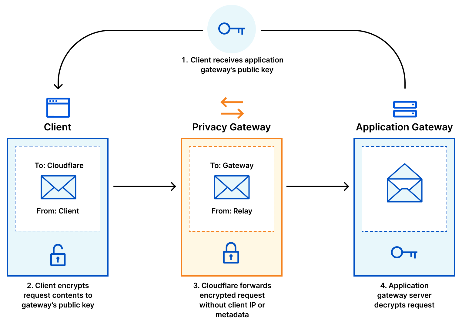
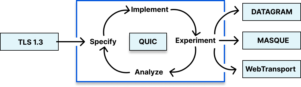
A little over 6 years ago, we presented quiche, our open source QUIC implementation written in Rust. Today we’re announcing the open sourcing of tokio-quiche, our battle-tested, asynchronous QUIC library combining both quiche and the Rust Tokio async runtime. Powering Cloudflare’s Proxy B in Apple iCloud Private Relay and our next-generation Oxy-based proxies, tokio-quiche handles millions of HTTP/3 requests per second with low latency and high throughput. tokio-quiche also powers Cloudflare Warp’s MASQUE client, replacing our WireGuard tunnels with QUIC-based tunnels, and the async version of h3i.
quiche was developed as a sans-io library, meaning that it implements the state machine required to handle the QUIC transport protocol while not making any assumptions about how its user intends to perform IO. This means that, with enough elbow grease, anyone can write an IO integration with quiche! This entails connecting or listening on a UDP socket, managing sending and receiving UDP datagrams on that socket while feeding all network information to quiche. Given we need this integration to be async, we’d have to do all this while integrating with an async Rust runtime. tokio-quiche does all of that for you, no grease required.
Lowering the barrier to entry
Originally, tokio-quiche was only used as the core of Oxy’s HTTP/3 server. But the spark to create tokio-quiche as a standalone library was our need for a MASQUE-capable HTTP/3 client. Our Zero Trust and Privacy Teams need MASQUE clients to tunnel data through WARP and our Privacy Proxies respectively, and we wanted to use the same technology to build both the client and server.
We initially open-sourced quiche to share our memory-safe QUIC and HTTP/3 implementation with as many stakeholders as possible. Our focus at the time was a low-level, sans-io design that could integrate into many types of software and be deployed widely. We achieved this goal, with quiche deployed in many different clients and servers. However, integrating sans-io libraries into applications is an error-prone and time-consuming process. Our aim with tokio-quiche is to lower the barrier of entry by providing much of the needed code ourselves.
Cloudflare alone embracing HTTP/3 is not of much use if others wanting to interact with our products and systems don’t also adopt it. Open sourcing tokio-quiche makes integration with our systems more straightforward, and helps propel the industry into the new standard of HTTP. By contributing tokio-quiche back to the Rust ecosystem, we hope to promote the development and usage of HTTP/3, QUIC and new privacy preserving technologies.
tokio-quiche has been used internally for some years now. This gave us time to refine and battle-test it, demonstrating that it can handle millions of RPS. tokio-quiche is not intended to be a standalone HTTP/3 client or server, but implements low-level protocols and allows for higher-level projects in the future. The README contains examples of server and client client event loops.
It’s actors all the way down
Tokio is a wildly popular asynchronous Rust runtime. It efficiently manages, schedules and executes the billions of asynchronous tasks which run on our edge. We use Tokio extensivelyatCloudflare, so we decided to tightly integrate quiche with it – thus the name, tokio-quiche. Under the hood, tokio-quiche uses actors to drive different parts of the QUIC and HTTP/3 state machine. Actors are small tasks with internal state that usually use message passing over channels to communicate with the outside world.
The actor model is a great abstraction to use for async-ifying sans-io libraries due to the conceptual similarities between the two. Both actors and sans-io libraries have some kind internal state which they want exclusive access to. They both usually interact with the outside world by sending and receiving “messages”. quiche’s “messages” are really raw byte buffers which represent incoming and outgoing network data. One of tokio-quiche’s “messages” is the Incoming struct which describes incoming UDP packets. Due to these similarities, async-ifying a sans-io library means: awaiting new messages or IO, translating the messages or IO into something the sans-io library understands, advancing the internal state machine, translating the state machine’s output to a message or IO, and finally sending the message or IO. (For more discussion on actors with Tokio, make sure to take a look at Alice Rhyl’s excellent blog post on the topic.)
The primary actor in tokio-quiche is the IO loop actor, which moves packets between quiche and the socket. Since QUIC is a transport protocol, it can carry any application protocol you want. HTTP/3 is quite common, but DNS over QUIC and the upcoming Media over QUIC are other examples. There’s even an RFC to help you create your own QUIC application! tokio-quiche exposes the ApplicationOverQuic trait to abstract over application protocols. The trait abstracts over quiche’s methods and the underlying I/O, allowing you to focus on your application logic. For example, our HTTP/3 debug and test client, h3i, is powered by a client-focused, non-HTTP/3 ApplicationOverQuic implementation.
Server Architecture Diagram
tokio-quiche ships with an HTTP/3-focused ApplicationOverQuic called H3Driver. H3Driver hooks up quiche’s HTTP/3 module to this IO loop to provide the building blocks for an async HTTP/3 client or server. The driver turns quiche’s raw HTTP/3 events into higher-level events and asynchronous body data streams, allowing you to respond to them in kind. H3Driver is itself generic, exposing ServerH3Driver and ClientH3Driver variants that each stack additional behavior on top of the core driver’s events.
Internal Data Flow
Inside tokio-quiche, we spawn two important tasks that facilitate data movement from a socket to quiche. The first is the InboundPacketRouter, which owns the receiving half of the socket and routes inbound datagrams by their connection ID (DCID) to a per-connection channel. The second task, the IoWorker actor, is the aforementioned IO loop and drives a single quiche Connection. It intersperses quiche calls with ApplicationOverQuic methods, ensuring you can inspect the connection before and after any IO interaction.
More blog posts on the creation of tokio-quiche are coming soon. We’ll discuss actor models and mutexes, UDP GRO and GSO, tokio task coop budgeting, and more.
Next up: more on QUIC and beyond!
tokio-quiche is an important foundation for Cloudflare’s investment into the QUIC and HTTP/3 ecosystem for Tokio – but it is still only a building block with its own complexity. In the future, we plan to release the same easy-to-use HTTP client and server abstractions that power our Oxy proxies and WARP clients today. Stay tuned for more blog posts on QUIC and HTTP/3 at Cloudflare, including an open-source client for customers of our Privacy Proxies and a completely new service that’s handling millions of RPS with tokio-quiche!
For now, check out the tokio-quiche crate on crates.io and its source code on GitHub to build your very own QUIC application. Could be a simple echo server, a DNS-over-QUIC client, a custom VPN, or even a fully-fledged HTTP server. Maybe you will beat us to the punch?
On April 10th, 2025 12:10 UTC, a security researcher notified Cloudflare of two vulnerabilities (CVE-2025-4820 and CVE-2025-4821) related to QUIC packet acknowledgement (ACK) handling, through our Public Bug Bounty program. These were DDoS vulnerabilities in the quiche library, and Cloudflare services that use it. quiche is Cloudflare’s open-source implementation of QUIC protocol, which is the transport protocol behind HTTP/3.
Upon notification, Cloudflare engineers patched the affected infrastructure, and the researcher confirmed that the DDoS vector was mitigated. Cloudflare’s investigation revealed no evidence that the vulnerabilities were being exploited or that any customers were affected. quiche versions prior to 0.24.4 were affected.
Here, we’ll explain why ACKs are important to Internet protocol design and how they help ensure fair network usage. Finally, we will explain the vulnerabilities and discuss our mitigation for the Optimistic ACK attack: a dynamic CWND-aware skip frequency that scales with a connection’s send rate.
Internet Protocols and Attack Vectors
QUIC is an Internet transport protocol that offers equivalent features to TCP (Transmission Control Protocol) and TLS (Transport Layer Security). QUIC runs over UDP (User Datagram Protocol), is encrypted by default and offers a few benefits over the prior set of protocols (including smaller handshake time, connection migration, and preventing head-of-line blocking that can manifest in TCP). Similar to TCP, QUIC relies on packet acknowledgements to make general progress. For example, ACKs are used for liveliness checks, validation, loss recovery signals, and congestion algorithm signals.
ACKs are an important source of signals for Internet protocols, which necessitates validation to ensure a malicious peer is not subverting these signals. Cloudflare’s QUIC implementation, quiche, lacked ACK range validation, which meant a peer could send an ACK range for packets never sent by the endpoint; this was patched in CVE-2025-4821. Additionally, a sophisticated attacker could mount an attack by predicting and preemptively sending ACKs (a technique called Optimistic ACK); this was patched in CVE-2025-4820. By exploiting the lack of ACK validation, an attacker can cause an endpoint to artificially expand its send rate; thereby gaining an unfair advantage over other connections. In the extreme case this can be a DDoS attack vector caused by higher server CPU utilization and an amplification of network traffic.
Fairness and Congestion control
A typical CDN setup includes hundreds of server processes, serving thousands of concurrent connections. Each connection has its own recovery and congestion control algorithm that is responsible for determining its fair share of the network. The Internet is a shared resource that relies on well-behaved transport protocols correctly implementing congestion control to ensure fairness.
To illustrate the point, let’s consider a shared network where the first connection (blue) is operating at capacity. When a new connection (green) joins and probes for capacity, it will trigger packet loss, thereby signaling the blue connection to reduce its send rate. The probing can be highly dynamic and although convergence might take time, the hope is that both connections end up sharing equal capacity on the network.
New connection joining the shared network. Existing flows make room for the new flow.
In order to ensure fairness and performance, each endpoint uses a Congestion Control algorithm. There are various algorithms but for our purposes let’s consider Cubic, a loss-based algorithm. Cubic, when in steady state, periodically explores higher sending rates. As the peer ACKs new packets, Cubic unlocks additional sending capacity (congestion window) to explore even higher send rates. Cubic continues to increase its send rate until it detects congestion signals (e.g., packet loss), indicating that the network is potentially at capacity and the connection should lower its sending rate.
Cubic congestion control responding to loss on the network.
The role of ACKs
ACKs are a feedback mechanism that Internet protocols use to make progress. A server serving a large file download will send that data across multiple packets to the client. Since networks are lossy, the client is responsible for ACKing when it has received a packet from the server, thus confirming delivery and progress. Lack of an ACK indicates that the packet has been lost and that the data might require retransmission. This feedback allows the server to confirm when the client has received all the data that it requested.
The server delivers packets and the client responds with ACKs.
The server delivers packets, but packet [2] is lost. The client responds with ACKs only for packets [1, 3], thereby signalling that packet [2] was lost.
In QUIC, packet numbers don’t have to be sequential; that means skipping packet numbers is natively supported. Additionally, a QUIC ACK Frame can contain gaps and multiple ACK ranges. As we will see, the built-in support for skipping packet numbers is a unique feature of QUIC (over TCP) that will help us enforce ACK validation.
The server delivering packets, but skipping packet [4]. The client responds with ACKs only for packets it received, and not sending an ACK for packet [4].
ACKs also provide signals that control an endpoint’s send rate and help provide fairness and performance. Delay between ACKs, variations in the delay, and lack of ACKs provide valuable signals, which suggest a change in the network and are important inputs to a congestion control algorithm.
Skipping packets to avoid ACK delay
QUIC allows endpoints to encode the ACK delay: the time by which the ACK for packet number ‘X’ was intentionally delayed from when the endpoint received packet number ‘X.’ This delay can result from normal packet processing or be an implementation-specific optimization. For example, since ACKs processing can be expensive (both for CPU and network), delaying ACKs can allow for batching and reducing the associated overhead.
However, since a delay in ACK signal also delays peer feedback, this can be detrimental for loss recovery. QUIC endpoints can therefore signal the peer to avoid delaying an ACK packet by skipping a packet number. This detail will become important as we will see later in the post.
Validating ACK range
It is expected that a well-behaved client should only send ACKs for packets that it has received. A lack of validation meant that it was possible for the client to send a very large ACK range for packets never sent by the server. For example, assuming the server has sent packets 0-5, a client was able to send an ACK Frame with the range 0-100.
By itself this is not actually a huge deal since quiche is smart enough to drop larger ACKs and only process ACKs for packets it has sent. However, as we will see in the next section, this made the Optimistic ACK vulnerability easier to exploit.
The fix was to enforce ACK range validation based on the largest packets sent by the server and close the connection on violation. This matches the RFC recommendation.
An endpoint SHOULD treat receipt of an acknowledgment for a packet it did not send as a connection error of type PROTOCOL_VIOLATION, if it is able to detect the condition. — https://www.rfc-editor.org/rfc/rfc9000#section-13.1
The server validating ACKs: the client sending ACK for packets [4..5] not sent by the server. The server closes the connection since ACK validation fails.
Optimistic ACK attack
In the following scenario, let’s assume the client is trying to mount an Optimistic ACK attack against the server. The goal of a client mounting the attack is to cause the server to send at a high rate. To achieve a high send rate, the client needs to deliver ACKs quickly back to the server, thereby providing an artificially low RTT / high bandwidth signal. Since packet numbers are typically monotonically increasing, a clever client can predict the next packet number and preemptively send ACKs (artificial ACK).
Optimistic ACK attack: the client predicting packets sent by the server and preemptively sending ACKs. ACK validation does not help here.
If the server has proper ACK validation, an invalid ACK for packets not yet sent by the server should trigger a connection close (without ACK range validation, the attack is trivial to execute). Therefore, a malicious client needs to be clever about pacing the artificial ACKs so they arrive just as the server has sent the packet. If the attack is done correctly, the server will see a very low RTT, and result in an inflated send rate.
An endpoint that acknowledges packets it has not received might cause a congestion controller to permit sending at rates beyond what the network supports. An endpoint MAY skip packet numbers when sending packets to detect this behavior. An endpoint can then immediately close the connection with a connection error of type PROTOCOL_VIOLATION — https://www.rfc-editor.org/rfc/rfc9000#section-21.4
Preventing an Optimistic ACK attack: the client predicting packets sent by the server and preemptively sending ACKs. Since the server skipped packet [4], it is able to detect the invalid ACK and close the connection.
The QUIC RFC mentions the Optimistic ACK attack and suggests skipping packets to detect this attack. By skipping packets, the client is unable to easily predict the next packet number and risks connection close if the server implements invalid ACK range validation. Implementation details – like how many packet numbers to skip and how often – are missing, however.
The [malicious] client transmission pattern does not indicate any malicious behavior.
As such, the bit rate towards the server follows normal behavior. Considering that QUIC packets are end-to-end encrypted, a middlebox cannot identify the attack by analyzing the client’s traffic. — MAY is not enough! QUIC servers SHOULD skip packet numbers
Ideally, the client would like to use as few resources as possible, while simultaneously causing the server to use as many as possible. In fact, as the security researchers confirmed in their paper: it is difficult to detect a malicious QUIC client using external traffic analysis, and it’s therefore necessary for QUIC implementations to mitigate the Optimistic ACK attack by skipping packets.
The Optimistic ACK vulnerability is not unique to QUIC. In fact the vulnerability was first discovered against TCP. However, since TCP does not natively support skipping packet numbers, an Optimistic ACK attack in TCP is harder to mitigate and can require additional DDoS analysis. By allowing for packet skipping, QUIC is able to prevent this type of attack at the protocol layer and more effectively ensure correctness and fairness over untrusted networks.
How often to skip packet numbers
According to the QUIC RFC, skipping packet numbers currently has two purposes. The first is to elicit a faster acknowledgement for loss recovery and the second is to mitigate an Optimistic ACK attack. A QUIC implementation skipping packets for Optimistic ACK attack therefore needs to skip frequently enough to mitigate the attack, while considering the effects on eliminating ACK delay.
Since packet skipping needs to be unpredictable, a simple implementation could be to skip packet numbers based on a random number from a static range. However, since the number of packets increases as the send rate increases, this has the downside of not adapting to the send rate. At smaller send rates, a static range will be too frequent, while at higher send rates it won’t be frequent enough and therefore be less effective. It’s also arguably most important to validate the send rate when there are higher send rates. It therefore seems necessary to adapt the skip frequency based on the send rate.
Congestion window (CWND) is a parameter used by congestion control algorithms to determine the amount of bytes that can be sent per round. Since the send rate increases based on the amount of bytes ACKed (capped by bytes sent), we claim that CWND makes a great proxy for dynamically adjusting the skip frequency. This CWND-aware skip frequency allows all connections, regardless of current send rate, to effectively mitigate the Optimistic ACK attack.
// c: the current packet number
// s: range of random packet number to skip from
//
// curr_pn
//  |
//  v                 |--- (upper - lower) ---|
// [c x x x x x x x x s s s s s s s s s s s s s x x]
//    |--min_skip---| |------skip_range-------|

const DEFAULT_INITIAL_CONGESTION_WINDOW_PACKETS: usize = 10;
const MIN_SKIP_COUNTER_VALUE: u64 = DEFAULT_INITIAL_CONGESTION_WINDOW_PACKETS * 2;

let packets_per_cwnd = (cwnd / max_datagram_size) as u64;
let lower = packets_per_cwnd / 2;
let upper = packets_per_cwnd * 2;

let skip_range = upper - lower;
let rand_skip_value = rand(skip_range);

let skip_pn = MIN_SKIP_COUNTER_VALUE + lower + rand_skip_value;
Skip frequency calculation in quiche.
Timeline
All timestamps are in UTC.
2025–04-10 12:10 – Cloudflare is notified of an ACK validation and Optimistic ACK vulnerability via the Bug Bounty Program.
2025-04-19 00:20 – Cloudflare confirms both vulnerabilities are reproducible and begins working on fix.
2025-05-02 20:12 – Security patch is complete and infrastructure patching starts.
2025–05-16 04:52 – Cloudflare infrastructure patching is complete.
New quiche version released.
Conclusion
We would like to sincerely thank Louis Navarre and Olivier Bonaventure from UCLouvain, who responsibly disclosed this issue via our Cloudflare Bug Bounty Program, allowing us to identify and mitigate the vulnerability. They also published a paper with their findings, notifying 10 other QUIC implementations that also suffered from the Optimistic ACK vulnerability.
We welcome further submissions from our community of researchers to continually improve the security of all of our products and open source projects.
A couple of months ago, a new paper demonstrated some new attacks against the Fiat-Shamir transformation. Quanta published a good article that explains the results.
This is a pretty exciting paper from a theoretical perspective, but I don’t see it leading to any practical real-world cryptanalysis. The fact that there are some weird circumstances that result in Fiat-Shamir insecurities isn’t new—many dozens of papers have been published about it since 1986. What this new result does is extend this known problem to slightly less weird (but still highly contrived) situations. But it’s a completely different matter to extend these sorts of attacks to “natural” situations.
What this result does, though, is make it impossible to provide general proofs of security for Fiat-Shamir. It is the most interesting result in this research area, and demonstrates that we are still far away from fully understanding what is the exact security guarantee provided by the Fiat-Shamir transform.
If you’ve ever taken a computer security class, you’ve probably learned about the three legs of computer security—confidentiality, integrity, and availability—known as the CIA triad. When we talk about a system being secure, that’s what we’re referring to. All are important, but to different degrees in different contexts. In a world populated by artificial intelligence (AI) systems and artificial intelligent agents, integrity will be paramount.
What is data integrity? It’s ensuring that no one can modify data—that’s the security angle—but it’s much more than that. It encompasses accuracy, completeness, and quality of data—all over both time and space. It’s preventing accidental data loss; the “undo” button is a primitive integrity measure. It’s also making sure that data is accurate when it’s collected—that it comes from a trustworthy source, that nothing important is missing, and that it doesn’t change as it moves from format to format. The ability to restart your computer is another integrity measure.
The CIA triad has evolved with the Internet. The first iteration of the Web—Web 1.0 of the 1990s and early 2000s—prioritized availability. This era saw organizations and individuals rush to digitize their content, creating what has become an unprecedented repository of human knowledge. Organizations worldwide established their digital presence, leading to massive digitization projects where quantity took precedence over quality. The emphasis on making information available overshadowed other concerns.
As Web technologies matured, the focus shifted to protecting the vast amounts of data flowing through online systems. This is Web 2.0: the Internet of today. Interactive features and user-generated content transformed the Web from a read-only medium to a participatory platform. The increase in personal data, and the emergence of interactive platforms for e-commerce, social media, and online everything demanded both data protection and user privacy. Confidentiality became paramount.
We stand at the threshold of a new Web paradigm: Web 3.0. This is a distributed, decentralized, intelligent Web. Peer-to-peer social-networking systems promise to break the tech monopolies’ control on how we interact with each other. Tim Berners-Lee’s open W3C protocol, Solid, represents a fundamental shift in how we think about data ownership and control. A future filled with AI agents requires verifiable, trustworthy personal data and computation. In this world, data integrity takes center stage.
For example, the 5G communications revolution isn’t just about faster access to videos; it’s about Internet-connected things talking to other Internet-connected things without our intervention. Without data integrity, for example, there’s no real-time car-to-car communications about road movements and conditions. There’s no drone swarm coordination, smart power grid, or reliable mesh networking. And there’s no way to securely empower AI agents.
In particular, AI systems require robust integrity controls because of how they process data. This means technical controls to ensure data is accurate, that its meaning is preserved as it is processed, that it produces reliable results, and that humans can reliably alter it when it’s wrong. Just as a scientific instrument must be calibrated to measure reality accurately, AI systems need integrity controls that preserve the connection between their data and ground truth.
This goes beyond preventing data tampering. It means building systems that maintain verifiable chains of trust between their inputs, processing, and outputs, so humans can understand and validate what the AI is doing. AI systems need clean, consistent, and verifiable control processes to learn and make decisions effectively. Without this foundation of verifiable truth, AI systems risk becoming a series of opaque boxes.
Recent history provides many sobering examples of integrity failures that naturally undermine public trust in AI systems. Machine-learning (ML) models trained without thought on expansive datasets have produced predictably biased results in hiring systems. Autonomous vehicles with incorrect data have made incorrect—and fatal—decisions. Medical diagnosis systems have given flawed recommendations without being able to explain themselves. A lack of integrity controls undermines AI systems and harms people who depend on them.
They also highlight how AI integrity failures can manifest at multiple levels of system operation. At the training level, data may be subtly corrupted or biased even before model development begins. At the model level, mathematical foundations and training processes can introduce new integrity issues even with clean data. During execution, environmental changes and runtime modifications can corrupt previously valid models. And at the output level, the challenge of verifying AI-generated content and tracking it through system chains creates new integrity concerns. Each level compounds the challenges of the ones before it, ultimately manifesting in human costs, such as reinforced biases and diminished agency.
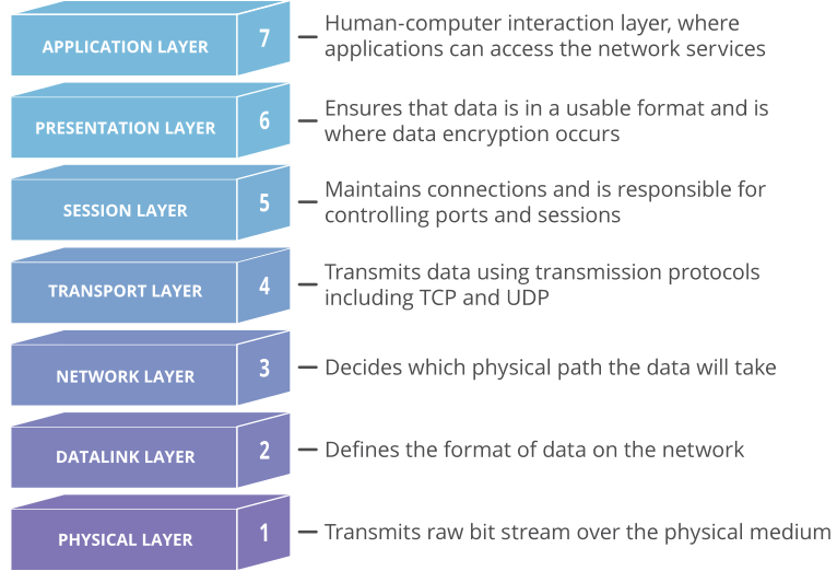
Think of it like protecting a house. You don’t just lock a door; you also use safe concrete foundations, sturdy framing, a durable roof, secure double-pane windows, and maybe motion-sensor cameras. Similarly, we need digital security at every layer to ensure the whole system can be trusted.
This layered approach to understanding security becomes increasingly critical as AI systems grow in complexity and autonomy, particularly with large language models (LLMs) and deep-learning systems making high-stakes decisions. We need to verify the integrity of each layer when building and deploying digital systems that impact human lives and societal outcomes.
At the foundation level, bits are stored in computer hardware. This represents the most basic encoding of our data, model weights, and computational instructions. The next layer up is the file system architecture: the way those binary sequences are organized into structured files and directories that a computer can efficiently access and process. In AI systems, this includes how we store and organize training data, model checkpoints, and hyperparameter configurations.
On top of that are the application layers—the programs and frameworks, such as PyTorch and TensorFlow, that allow us to train models, process data, and generate outputs. This layer handles the complex mathematics of neural networks, gradient descent, and other ML operations.
Finally, at the user-interface level, we have visualization and interaction systems—what humans actually see and engage with. For AI systems, this could be everything from confidence scores and prediction probabilities to generated text and images or autonomous robot movements.
Why does this layered perspective matter? Vulnerabilities and integrity issues can manifest at any level, so understanding these layers helps security experts and AI researchers perform comprehensive threat modeling. This enables the implementation of defense-in-depth strategies—from cryptographic verification of training data to robust model architectures to interpretable outputs. This multi-layered security approach becomes especially crucial as AI systems take on more autonomous decision-making roles in critical domains such as healthcare, finance, and public safety. We must ensure integrity and reliability at every level of the stack.
The risks of deploying AI without proper integrity control measures are severe and often underappreciated. When AI systems operate without sufficient security measures to handle corrupted or manipulated data, they can produce subtly flawed outputs that appear valid on the surface. The failures can cascade through interconnected systems, amplifying errors and biases. Without proper integrity controls, an AI system might train on polluted data, make decisions based on misleading assumptions, or have outputs altered without detection. The results of this can range from degraded performance to catastrophic failures.
We see four areas where integrity is paramount in this Web 3.0 world. The first is granular access, which allows users and organizations to maintain precise control over who can access and modify what information and for what purposes. The second is authentication—much more nuanced than the simple “Who are you?” authentication mechanisms of today—which ensures that data access is properly verified and authorized at every step. The third is transparent data ownership, which allows data owners to know when and how their data is used and creates an auditable trail of data providence. Finally, the fourth is access standardization: common interfaces and protocols that enable consistent data access while maintaining security.
Luckily, we’re not starting from scratch. There are open W3C protocols that address some of this: decentralized identifiers for verifiable digital identity, the verifiable credentials data model for expressing digital credentials, ActivityPub for decentralized social networking (that’s what Mastodon uses), Solid for distributed data storage and retrieval, and WebAuthn for strong authentication standards. By providing standardized ways to verify data provenance and maintain data integrity throughout its lifecycle, Web 3.0 creates the trusted environment that AI systems require to operate reliably. This architectural leap for integrity control in the hands of users helps ensure that data remains trustworthy from generation and collection through processing and storage.
Integrity is essential to trust, on both technical and human levels. Looking forward, integrity controls will fundamentally shape AI development by moving from optional features to core architectural requirements, much as SSL certificates evolved from a banking luxury to a baseline expectation for any Web service.
Web 3.0 protocols can build integrity controls into their foundation, creating a more reliable infrastructure for AI systems. Today, we take availability for granted; anything less than 100% uptime for critical websites is intolerable. In the future, we will need the same assurances for integrity. Success will require following practical guidelines for maintaining data integrity throughout the AI lifecycle—from data collection through model training and finally to deployment, use, and evolution. These guidelines will address not just technical controls but also governance structures and human oversight, similar to how privacy policies evolved from legal boilerplate into comprehensive frameworks for data stewardship. Common standards and protocols, developed through industry collaboration and regulatory frameworks, will ensure consistent integrity controls across different AI systems and applications.
Just as the HTTPS protocol created a foundation for trusted e-commerce, it’s time for new integrity-focused standards to enable the trusted AI services of tomorrow.
Here’s an easy system for two humans to remotely authenticate to each other, so they can be sure that neither are digital impersonations.
To mitigate that risk, I have developed this simple solution where you can setup a unique time-based one-time passcode (TOTP) between any pair of persons.
This is how it works:
Two people, Person A and Person B, sit in front of the same computer and open this page;
They input their respective names (e.g. Alice and Bob) onto the same page, and click “Generate”;
The page will generate two TOTP QR codes, one for Alice and one for Bob;
Alice and Bob scan the respective QR code into a TOTP mobile app (such as Authy or Google Authenticator) on their respective mobile phones;
In the future, when Alice speaks with Bob over the phone or over video call, and wants to verify the identity of Bob, Alice asks Bob to provide the 6-digit TOTP code from the mobile app. If the code matches what Alice has on her own phone, then Alice has more confidence that she is speaking with the real Bob.
Have you ever built a piece of IKEA furniture, or put together a LEGO set, by following the instructions closely and only at the end realized at some point you didn’t quite follow them correctly? The final result might be close to what was intended, but there’s a nagging thought that maybe, just maybe, it’s not as rock steady or functional as it could have been.
Internet protocol specifications are instructions designed for engineers to build things. Protocol designers take great care to ensure the documents they produce are clear. The standardization process gathers consensus and review from experts in the field, to further ensure document quality. Any reasonably skilled engineer should be able to take a specification and produce a performant, reliable, and secure implementation. The Internet is central to everyone’s lives, and we depend on these implementations. Any deviations from the specification can put us at risk. For example, mishandling of malformed requests can allow attacks such as request smuggling.
h3i is a binary command line tool and Rust library designed for low-level testing and debugging of HTTP/3, which runs over QUIC. h3i is free and open source as part of Cloudflare’s quiche project. In this post we’ll explain the motivation behind developing h3i, how we use it to help develop robust and safe standards-compliant software and production systems, and how you can similarly use it to test your own software or services. If you just want to jump into how to use h3i, go to the h3i command line tool section.
A recap of QUIC and HTTP/3
QUIC is a secure-by-default transport protocol that provides performance advantages compared to TCP and TLS via a more efficient handshake, along with stream multiplexing that provides head-of-line blocking avoidance. HTTP/3 is an application protocol that maps HTTP semantics to QUIC, such as defining how HTTP requests and responses are assigned to individual QUIC streams.
Cloudflare has supported QUIC on our global network in some shape or form since 2018. We started while the Internet Engineering Task Force (IETF) was earnestly standardizing the protocol, working through early iterations and using interoperability testing and experience to help provide feedback for the standards process. We launched support for QUIC version 1 and HTTP/3 as soon as RFC 9000 (and its accompanying specifications) were published in 2021.
We work on the Protocols team, who own the ingress proxy into the Cloudflare network. This is essentially Cloudflare’s “front door” — HTTP requests that come to Cloudflare from the Internet pass through us first. The majority of requests are passed onwards to things like rulesets, workers, caches, or a customer origin. However, you might be surprised that many requests don’t ever make it that far because they are, in some way, invalid or malformed. Servers listening on the Internet have to be robust to traffic that is not RFC compliant, whether caused by accident or malicious intent.
The Protocols team actively participates in IETF standardization work and has also helped build and maintain other Cloudflare services that leverage quiche for QUIC and HTTP/3, from the proxies that help iCloud Private Relay via MASQUE proxying, to replacing WARP’s use of Wireguard with MASQUE, and beyond.
Throughout all of these different use cases, it is important for us to extensively test all aspects of the protocols. A deep dive into protocol details is a blog post (or three) in its own right. So let’s take a thin slice across HTTP to help illustrate the concepts.
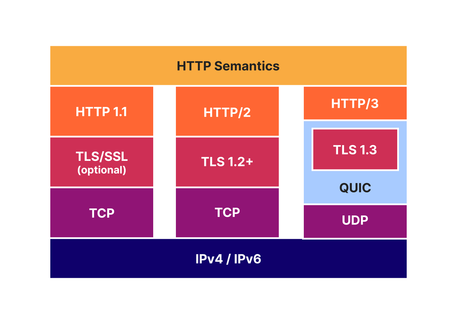
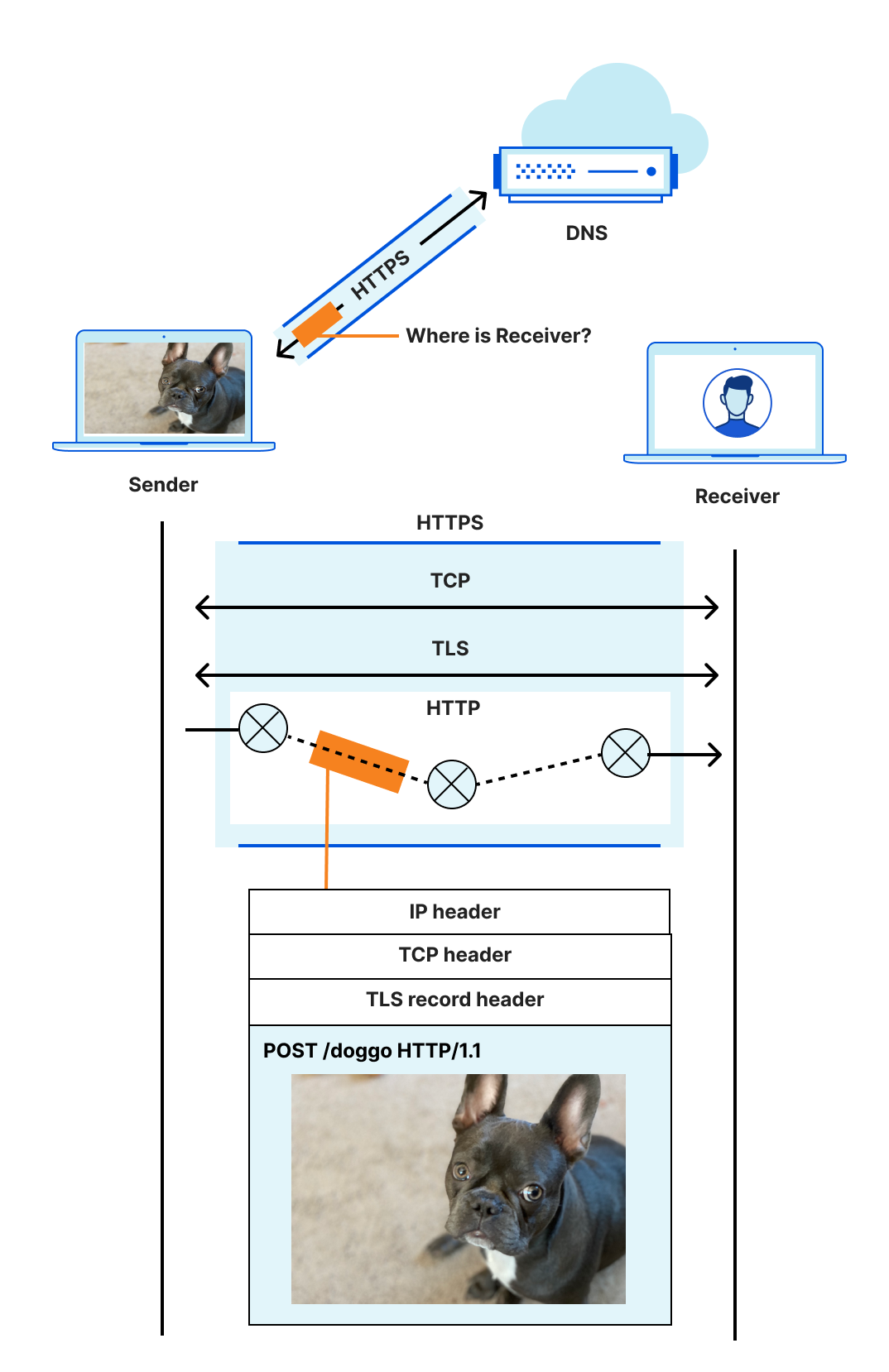
HTTP Semantics are common to all versions of HTTP — the overall architecture, terminology, and protocol aspects such as request and response messages, methods, status codes, header and trailer fields, message content, and much more. Each individual HTTP version defines how semantics are transformed into a “wire format” for exchange over the Internet. You can read more about HTTP/1.1 and HTTP/2 in some of our previous blogposts.
With HTTP/3, HTTP request and response messages are split into a series of binary frames. HEADERS frames carry a representation of HTTP metadata (method, path, status code, field lines). The payload of the frame is the encoded QPACK compression output. DATA frames carry HTTP content (aka “message body”). In order to exchange these frames, HTTP/3 relies on QUIC streams. These provide an ordered and reliable byte stream and each have an identifier (ID) that is unique within the scope of a connection. There are four different stream types, denominated by the two least significant bits of the ID.
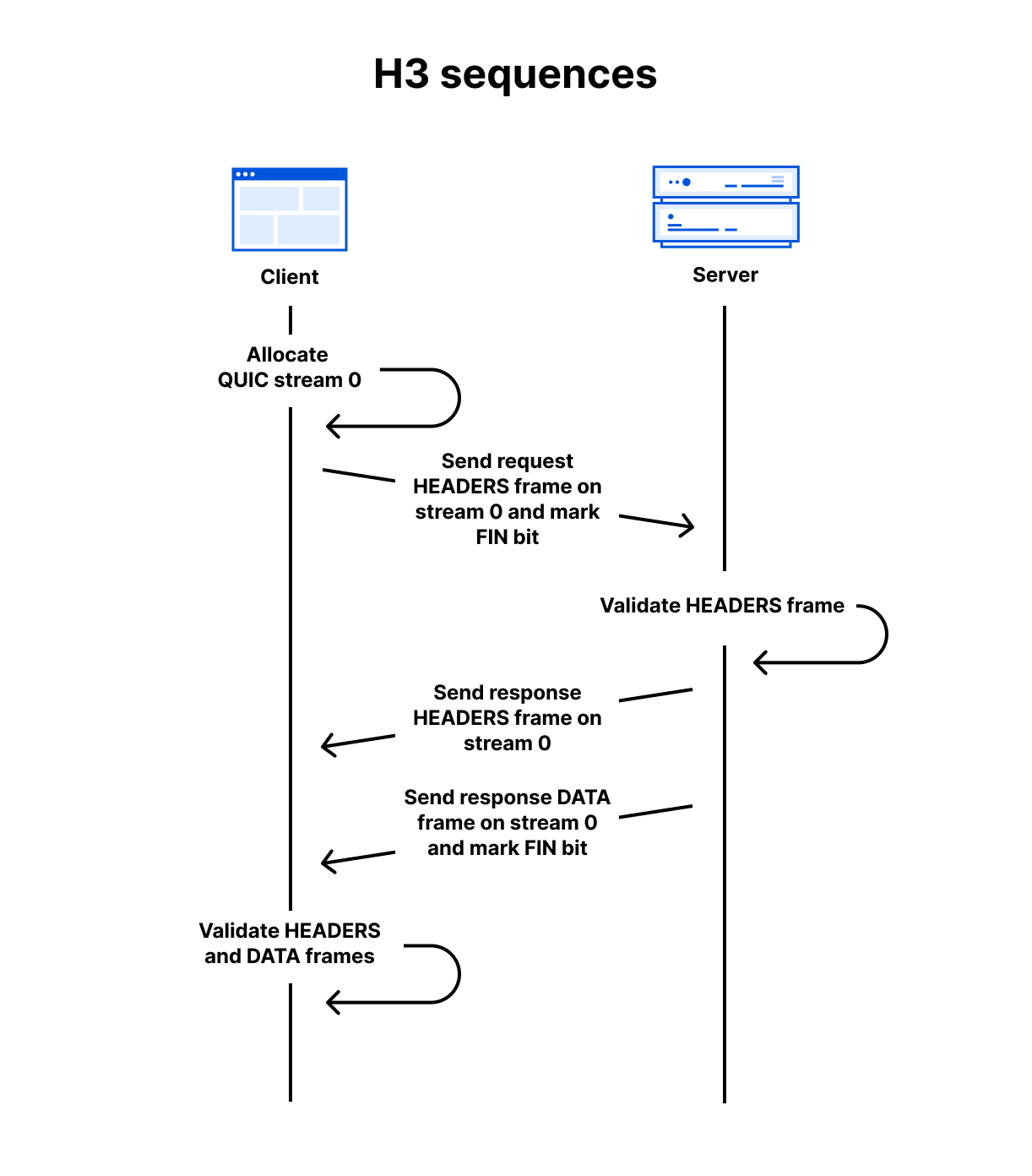
As a simple example, assuming a QUIC connection has already been established, a client can make a GET request and receive a 200 OK response with an HTML body using the follow sequence:
Client allocates the first available client-initiated bidirectional QUIC stream. (The IDs start at 0, then 4, 8, 12 and so on)
Client sends the request HEADERS frame on the stream and sets the stream’s FIN bit to mark the end of stream.
Server receives the request HEADERS frame and validates it against RFC 9114 rules. If accepted, it processes the request and prepares the response.
Server sends the response HEADERS frame on the same stream.
Server sends the response DATA frame on the same stream and sets the FIN bit.
Client receives the response frames and validates them. If accepted, the content is presented to the user.
At the QUIC layer, stream data is split into STREAM frames, which are sent in QUIC packets over UDP. QUIC deals with any loss detection and recovery, helping to ensure stream data is reliable. The layer cake diagram below provides a handy comparison of how HTTP/1.1, HTTP/2 and HTTP/3 use TCP, UDP and IP.
Background on testing QUIC and HTTP/3 at Cloudflare
The Protocols team has a diverse set of automated test tools that exercise our ingress proxy software in order to ensure it can stand up to the deluge that the Internet can throw at it. Just like a bouncer at a nightclub front door, we need to prevent as much bad traffic as possible before it gets inside and potentially causes damage.
HTTP/2 and HTTP/3 share several concepts. When we started developing early HTTP/3 support, we’d already learned a lot from production experience with HTTP/2. While HTTP/2 addressed many issues with HTTP/1.1 (especially problems like request smuggling, caused by its ASCII-based message delineation), HTTP/2 also added complexity and new avenues for attack. Security is an ongoing process, and the Protocols team continually hardens our software and systems to threats. For example, mitigating the range of denial-of-service attacks identified by Netflix in 2019, or the HTTP/2 Rapid Reset attacks of 2023.
For testing HTTP/2, we rely on the Python Requests library for testing conventional HTTP exchanges. However, that mostly only exercises HEADERS and DATA frames. There are eight other frame types and a plethora of ways that they can interact (hence the new attack vectors mentioned above). In order to get full testing coverage, we have to break down into the lower layer h2 library, which allows exact frame-by-frame control. However, even that is not always enough. Libraries tend to want to follow the RFC rules and prevent their users from doing “the wrong thing”. This is entirely logical for most purposes. For our needs though, we need to take off the safety guards just like any potential attackers might do. We have a few cases where the best way to exercise certain traffic patterns is to handcraft HTTP/2 frames in a hex editor, store that as binary, and replay it with a tool such as OpenSSL s_client.
We knew we’d need similar testing approaches for HTTP/3. However, when we started in 2018, there weren’t many other suitable client implementations. The rate of iteration on the specifications also meant it was hard to always keep in sync. So we built tests on quiche, using a mix of our quiche-client and http3_test. Over time, the python library aioquic has matured, and we have used it to add a range of lower-layer tests that break or bend HTTP/3 rules, in order to prove our proxies are robust.
Finally, we would be remiss not to mention that all the tests in our ingress proxy are in addition to the suite of over 500 integration tests that run on the quiche project itself.
Making HTTP/3 testing more accessible and maintainable with h3i
While we are happy with the coverage of our current tests, the smorgasbord of test tools makes it hard to know what to reach for when adding new tests. For example, we’ve had cases where aioquic’s safety guards prevent us from doing something, and it has needed a patch or workaround. This sort of thing requires a time investment just to debug/develop the tests.
We believe it shouldn’t take a protocol or code expert to develop what are often very simple to describe tests. While it is important to provide guide rails for the majority of conventional use cases, it is also important to provide accessible methods for taking them off.
Let’s consider a simple example. In HTTP/3 there is something called the control stream. It’s used to exchange frames such as SETTINGS, which affect the HTTP/3 connection. RFC 9114 Section 6.2.1 states:
Each side MUST initiate a single control stream at the beginning of the connection and send its SETTINGS frame as the first frame on this stream. If the first frame of the control stream is any other frame type, this MUST be treated as a connection error of type H3_MISSING_SETTINGS. Only one control stream per peer is permitted; receipt of a second stream claiming to be a control stream MUST be treated as a connection error of type H3_STREAM_CREATION_ERROR. The sender MUST NOT close the control stream, and the receiver MUST NOT request that the sender close the control stream. If either control stream is closed at any point, this MUST be treated as a connection error of type H3_CLOSED_CRITICAL_STREAM. Connection errors are described in Section 8.
There are many tests we can conjure up just from that paragraph:
Send a non-SETTINGS frame as the first frame on the control stream.
Open two control streams.
Open a control stream and then close it with a FIN bit.
Open a control stream and then reset it with a RESET_STREAM QUIC frame.
Wait for the peer to open a control stream and then ask for it to be reset with a STOP_SENDING QUIC frame.
All of the above actions should cause a remote peer that has implemented the RFC properly to close the connection. Therefore, it is not in the interest of the local client or server applications to ever do these actions.
Many QUIC and HTTP/3 implementations are developed as libraries that are integrated into client or server applications. There may be an extensive set of unit or integration tests of the library checking RFC rules. However, it is also important to run the same tests on the integrated assembly of library and application, since it’s all too common that an unhandled/mishandled library error can cascade to cause issues in upper layers. For instance, the HTTP/2 Rapid Reset attacks affected Cloudflare due to their impact on how one service spoke to another.
We’ve developed h3i, a command line tool and library, to make testing more accessible and maintainable for all. We started with a client that can exercise servers, since that’s what our focus has been. Future developments could support the opposite, a server that behaves in unusual ways in order to exercise clients.
Note: h3i is not intended to be a production client! Its flexibility may cause issues that are not observed in other production-oriented clients. It is also not intended to be used for any type of performance testing and measurement.
The h3i command line tool
The primary purpose of the h3i command line tool is quick low-level debugging and exploratory testing. Rather than worrying about writing code or a test script, users can quickly run an ad-hoc client test against a target, guided by interactive prompts.
In the simplest case, you can think of h3i a bit like curl but with access to some extra HTTP/3 parameters. In the example below, we issue a request to https://cloudflare-quic.com/ and receive a response.
Walking through a simple GET with h3i step-by-step:
Grab a copy of the h3i binary either by running cargo install h3i or cloning the quiche source repo at https://github.com/cloudflare/quiche/. Both methods assume you have some familiarity with Rust and Cargo. See the cargo documentation for more information.
cargo install will place the binary on your path, so you can then just run it by executing h3i.
If running from source, navigate to the quiche/h3i directory and then use cargo run.
Run the binary and provide the name and port of the target server. If the port is omitted, the default value 443 is assumed. E.g, cargo run cloudflare-quic.com
h3i then enters the action prompting phase. A series of one or more HTTP/3 actions can be queued up, such as sending frames, opening or terminating streams, or waiting on data from the server. The full set of options is documented in the readme.
The prompting interface adapts to keyboard inputs and supports tab completion.
In the example above, the headers action is selected, which walks through populating the fields in a HEADERS frame. It includes mandatory fields from RFC 9114 for convenience. If a test requires omitting these, the headers_no_pseudo can be used instead.
The commit prompt choice finalizes the action list and moves to the connection phase. h3i initiates a QUIC connection to the server identified in step 2. Once connected, actions are executed in order.
By default, h3i reports some limited information about the frames the server sent. To get more detailed information, the RUST_LOG environment can be set with either debug or trace levels.
Instant record and replay, powered by qlog
It can be fun to play around with the h3i command line tool to see how different servers respond to different combinations or sequences of actions. Occasionally, you’ll find a certain set that you want to run over and over again, or share with a friend or colleague. Having to manually enter the prompts repeatedly, or share screenshots of the h3i input can turn tedious. Fortunately, h3i records all the actions in a log file by default — the file path is printed immediately after h3i starts. The format of this file is based on qlog, an in-progress standard in development at the IETF for network protocol logging. It’s a perfect fit for our low-level needs.
h3i logs can be replayed using the --qlog-input option. You can change the target server host and port, and keep all the same actions. However, most servers will validate the :authority pseudo-header or Host header contained in a HEADERS frame. The –replay-host-override option allows changing these fields without needing to modify the file by hand.
And yes, qlog files are human-readable text in the JSON-SEQ format. So you can also just write these by hand in the first place if you like! However, if you’re going to start writing things, maybe Rust is your preferred option…
Using the h3i library to send a malformed request with Rust
In our previous example, we just sent a valid request so there wasn’t anything interesting to observe. Where h3i really shines is in generating traffic that isn’t RFC compliant, such as malformed HTTP messages, invalid frame sequences, or other actions on streams. This helps determine if a server is acting robustly and defensively.
Let’s explore this more with an example of HTTP content-length mismatch. RFC 9114 section 4.1.2 specifies:
A request or response that is defined as having content when it contains a Content-Length header field (Section 8.6 of [HTTP]) is malformed if the value of the Content-Length header field does not equal the sum of the DATA frame lengths received. A response that is defined as never having content, even when a Content-Length is present, can have a non-zero Content-Length header field even though no content is included in DATA frames.
Intermediaries that process HTTP requests or responses (i.e., any intermediary not acting as a tunnel) MUST NOT forward a malformed request or response. Malformed requests or responses that are detected MUST be treated as a stream error of type H3_MESSAGE_ERROR.
For malformed requests, a server MAY send an HTTP response indicating the error prior to closing or resetting the stream.
There are good reasons that the RFC is so strict about handling mismatched content lengths. They can be a vector for desynchronization attacks (similar to request smuggling), especially when a proxy is converting inbound HTTP/3 to outbound HTTP/1.1.
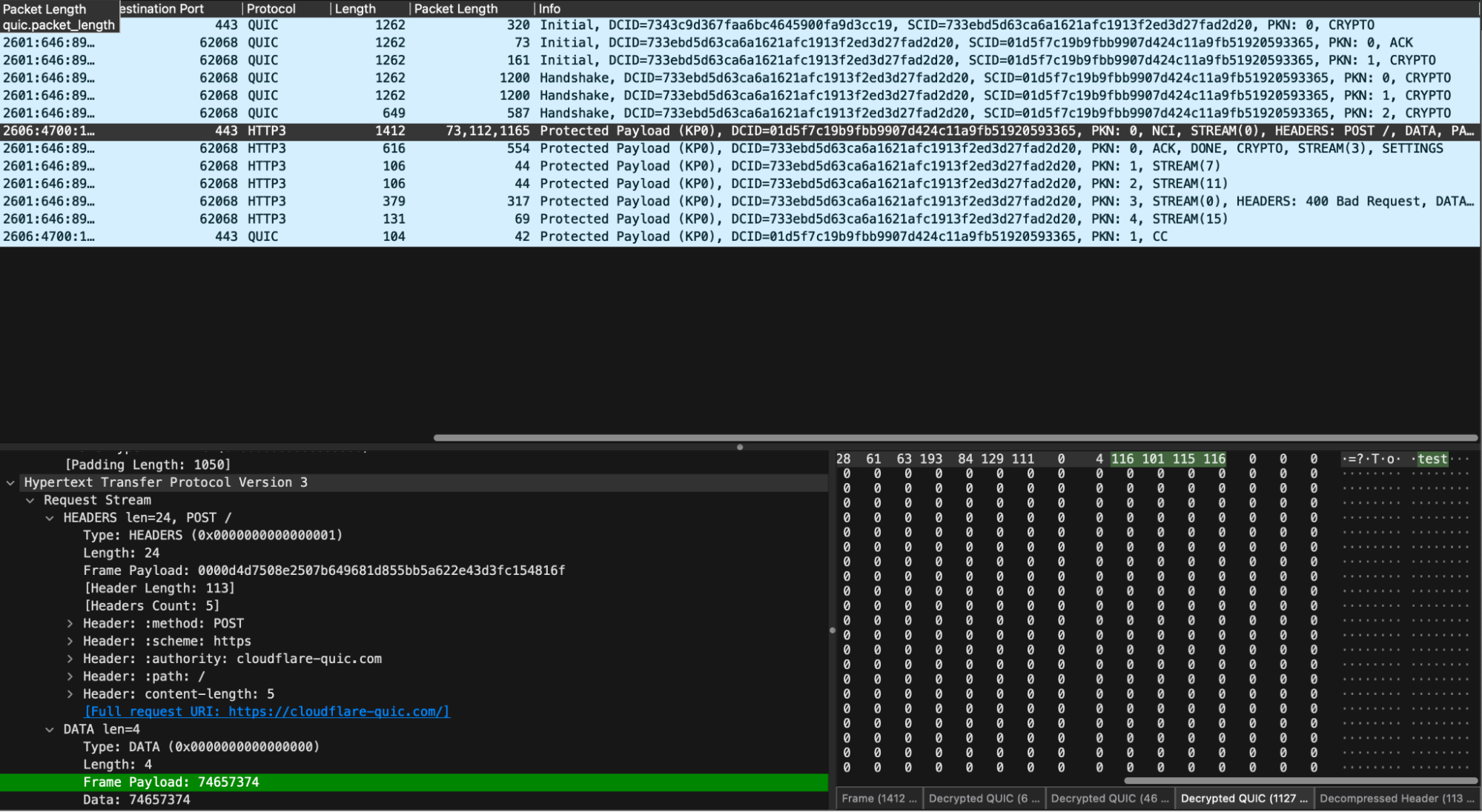
We’ve provided an example of how to use the h3i Rust library to write a tailor-made test client that sends a mismatched content length request. It sends a Content-Length header of 5, but its body payload is “test”, which is only 4 bytes. It then waits for the server to respond, after which it explicitly closes the connection by sending a QUIC CONNECTION_CLOSE frame.
When running low-level tests, it can be interesting to also take a packet capture (pcap) and observe what is happening on the wire. Since QUIC is an encrypted transport, we’ll need to use the SSLKEYLOG environment variable to capture the session keys so that tools like Wireshark can decrypt and dissect.
To follow along at home, clone a copy of the quiche repository, start a packet capture on the appropriate network interface and then run:
cd quiche/h3i
SSLKEYLOGFILE="h3i-example.keys" cargo run --example content_length_mismatch
In our decrypted capture, we see the expected sequence of handshake, request, response, and then closure.
Surveying the example code
The example is a simple binary app with a main() entry point. Let’s survey the key elements.
First, we set up an h3i configuration to a target server:
let config = Config::new()
        .with_host_port("cloudflare-quic.com".to_string())
        .with_idle_timeout(2000)
        .build()
        .unwrap();
The idle timeout is a QUIC concept which tells each endpoint when it should close the connection if the connection has been idle. This prevents endpoints from spinning idly if the peer hasn’t closed the connection. h3i’s default is 30 seconds, which can be too long for tests, so we set ours to 2 seconds here.
Next, we define a set of request headers and encode them with QPACK compression, ready to put in a HEADERS frame. Note that h3i does provide a send_headers_frame helper method which does this for you, but the example does it manually for clarity:
let headers = vec![
        Header::new(b":method", b"POST"),
        Header::new(b":scheme", b"https"),
        Header::new(b":authority", b"cloudflare-quic.com"),
        Header::new(b":path", b"/"),
        // We say that we're going to send a body with 5 bytes...
        Header::new(b"content-length", b"5"),
    ];

    let header_block = encode_header_block(&headers).unwrap();
Then, we define the set of h3i actions that we want to execute in order: send HEADERS, send a too-short DATA frame, wait for the server’s HEADERS, then close the connection.
let actions = vec![
        Action::SendHeadersFrame {
            stream_id: STREAM_ID,
            fin_stream: false,
            headers,
            frame: Frame::Headers { header_block },
        },
        Action::SendFrame {
            stream_id: STREAM_ID,
            fin_stream: true,
            frame: Frame::Data {
                // ...but, in actuality, we only send 4 bytes. This should yield a
                // 400 Bad Request response from an RFC-compliant
                // server: https://datatracker.ietf.org/doc/html/rfc9114#section-4.1.2-3
                payload: b"test".to_vec(),
            },
        },
        Action::Wait {
            wait_type: WaitType::StreamEvent(StreamEvent {
                stream_id: STREAM_ID,
                event_type: StreamEventType::Headers,
            }),
        },
        Action::ConnectionClose {
            error: quiche::ConnectionError {
                is_app: true,
                error_code: quiche::h3::WireErrorCode::NoError as u64,
                reason: vec![],
            },
        },
    ];
Finally, we’ll set things in motion with connect(), which sets up the QUIC connection, executes the actions list and collects the summary.
let summary =
        sync_client::connect(config, &actions).expect("connection failed");

    println!(
        "=== received connection summary! ===\n\n{}",
        serde_json::to_string_pretty(&summary).unwrap_or_else(|e| e.to_string())
    );
ConnectionSummary provides data about the connection, including the frames h3i received, details about why the connection closed, and connection statistics. The example prints the summary out. However, you can programmatically check it. We do this to write our own internal automation tests.
If you’re running the example, it should print something like the following:
Let’s walk through the output. Up first is the StreamMap, which is a record of all frames received on each stream. We can see that we received 5 frames on stream 0: 2 UNKNOWNs, one EnrichedHeaders frame, and two DATA frames.
The UNKNOWN frames are extension frames that are unknown to h3i; the server under test is sending what are known as GREASE frames to help exercise the protocol and ensure clients are not erroring when they receive something unexpected per RFC 9114 requirements.
The EnrichedHeaders frame is essentially an HTTP/3 HEADERS frame, but with some small helpers, like one to get the response status code. The server under test sent a 400 as expected.
The DATA frames carry response body bytes. In this case, the body is the HTML required to render the Cloudflare Bad Request page (you can peek at the HTML yourself in Wireshark). We chose to omit the raw bytes from the ConnectionSummary since they may not be representable safely as text. A future improvement could be to encode the bytes in base64 or hex, in order to support tests that need to check response content.
h3i for test automation
We believe h3i is a great library for building automated tests on. You can take the above example and modify it to fit within various types of (continuous) integration tests.
We outlined earlier how the Protocols team HTTP/3 testing has organically grown to use three different frameworks. Even within those, we still didn’t have much flexibility and ease of use. Over the last year we’ve been building h3i itself and reimplementing our suite of ingress proxy test cases using the Rust library. This has helped us improve test coverage with a range of new tests not previously possible. It also surprisingly identified some problems with the old tests, particularly for some edge cases where it wasn’t clear how the old test code implementation was running under the hood.
Bake offs, interop, and wider testing of HTTP
RFC 1025 was published in 1987. Authored by Jon Postel, it discusses bake offs:
In the early days of the development of TCP and IP, when there were very few implementations and the specifications were still evolving, the only way to determine if an implementation was “correct” was to test it against other implementations and argue that the results showed your own implementation to have done the right thing. These tests and discussions could, in those early days, as likely change the specification as change the implementation.
There were a few times when this testing was focused, bringing together all known implementations and running through a set of tests in hopes of demonstrating the N squared connectivity and correct implementation of the various tricky cases. These events were called “Bake Offs”.
While nearly 4 decades old, the concept of exercising Internet protocol implementations and seeing how they compare to the specification still holds true. The QUIC WG made heavy use of interoperability testing through its standardization process. We started off sitting in a room and running tests manually by hand (or with some help from scripts). Then Marten Seemann developed the QUIC Interop Runner, which runs regular automated testing and collects and renders all the results. This has proven to be incredibly useful.
The state of HTTP/3 interoperability testing is not quite as mature. Although there are tools such as Kazu Yamamoto’s excellent h3spec (in Haskell) for testing conformance, there isn’t a similar continuous integration process of collection and rendering of results. While h3i shares similarities with h3spec, we felt it important to focus on the framework capabilities rather than creating a corpus of tests and assertions. Cloudflare is a big fan of Rust and as several teams move to Rust-based proxies, having a consistent ecosystem provides advantages (such as developer velocity).
We certainly feel there is a great opportunity for continued collaboration and cross-pollination between projects in the QUIC and HTTP space. For example, h3i might provide a suitable basis to build another tool (or set of scripts) to run bake offs or interop tests. Perhaps it even makes sense to have a common collection of test cases owned by the community, that can be specialized to the most appropriate or preferred tooling. This topic was recently presented at the HTTP Workshop 2024 by Mohammed Al-Sahaf, and it excites us to see new potential directions of testing improvements.
When using any tools or methods for protocol testing, we encourage responsible handling of security-related matters. If you believe you may have identified a vulnerability in an IETF Internet protocol itself, please follow the IETF’s reporting guidance. If you believe you may have discovered an implementation vulnerability in a product, open source project, or service using QUIC or HTTP, then you should report these directly to the responsible party. Implementers or operators often provide their own publicly-available guidance and contact details to send reports. For example, the Cloudflare quiche security policy is available in the Security tab of the GitHub repository.
Summary and outlook
Cloudflare takes testing very seriously. While h3i has a limited feature set as a test HTTP/3 client, we believe it provides a strong framework that can be extended to a wider range of different cases and different protocols. For example, we’d like to add support for low-level HTTP/2.
We’ve designed h3i to integrate into a wide range of testing methodologies, from manual ad-hoc testing, to native Rust tests, to conformance testbenches built with scripting languages. We’ve had great success migrating our existing zoo of test tools to a single one that is more accessible and easier to maintain.
Now that you’ve read about h3i’s capabilities, it’s left as an exercise to the reader to go back to the example of HTTP/3 control streams and consider how you could write tests to exercise a server.
We encourage the community to experiment with h3i and provide feedback, and propose ideas or contributions to the GitHub repository as issues or Pull Requests.
Abstract: The recently published “MERGE” protocol is designed to be used in the prototype CAC-vote system. The voting kiosk and protocol transmit votes over the internet and then transmit voter-verifiable paper ballots through the mail. In the MERGE protocol, the votes transmitted over the internet are used to tabulate the results and determine the winners, but audits and recounts use the paper ballots that arrive in time. The enunciated motivation for the protocol is to allow (electronic) votes from overseas military voters to be included in preliminary results before a (paper) ballot is received from the voter. MERGE contains interesting ideas that are not inherently unsound; but to make the system trustworthy—to apply the MERGE protocol—would require major changes to the laws, practices, and technical and logistical abilities of U.S. election jurisdictions. The gap between theory and practice is large and unbridgeable for the foreseeable future. Promoters of this research project at DARPA, the agency that sponsored the research, should acknowledge that MERGE is internet voting (election results rely on votes transmitted over the internet except in the event of a full hand count) and refrain from claiming that it could be a component of trustworthy elections without sweeping changes to election law and election administration throughout the U.S.
New attack against the RADIUS authentication protocol:
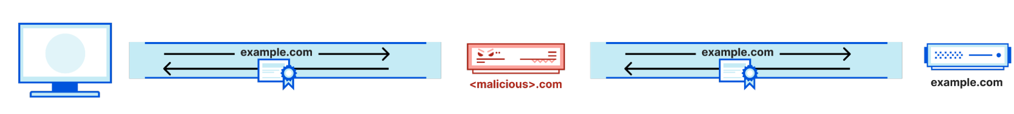
The Blast-RADIUS attack allows a man-in-the-middle attacker between the RADIUS client and server to forge a valid protocol accept message in response to a failed authentication request. This forgery could give the attacker access to network devices and services without the attacker guessing or brute forcing passwords or shared secrets. The attacker does not learn user credentials.
This is one of those vulnerabilities that comes with a cool name, its own website, and a logo.
On March 27 the commission asked telecommunications providers to weigh in and detail what they are doing to prevent SS7 and Diameter vulnerabilities from being misused to track consumers’ locations.
The FCC has also asked carriers to detail any exploits of the protocols since 2018. The regulator wants to know the date(s) of the incident(s), what happened, which vulnerabilities were exploited and with which techniques, where the location tracking occurred, and if known the attacker’s identity.
This time frame is significant because in 2018, the Communications Security, Reliability, and Interoperability Council (CSRIC), a federal advisory committee to the FCC, issued several security best practices to prevent network intrusions and unauthorized location tracking.
It is no secret that Cloudflare is encouraging companies to deprecate their use of IPv4 addresses and move to IPv6 addresses. We have a couple articles on the subject from this year:
And many more in our catalog. To help with this, we spent time this last year investigating and implementing infrastructure to reduce our internal and egress use of IPv4 addresses. We prefer to re-allocate our addresses than to purchase more due to increasing costs. And in this effort we discovered that our cache service is one of our bigger consumers of IPv4 addresses. Before we remove IPv4 addresses for our cache services, we first need to understand how cache works at Cloudflare.
How does cache work at Cloudflare?
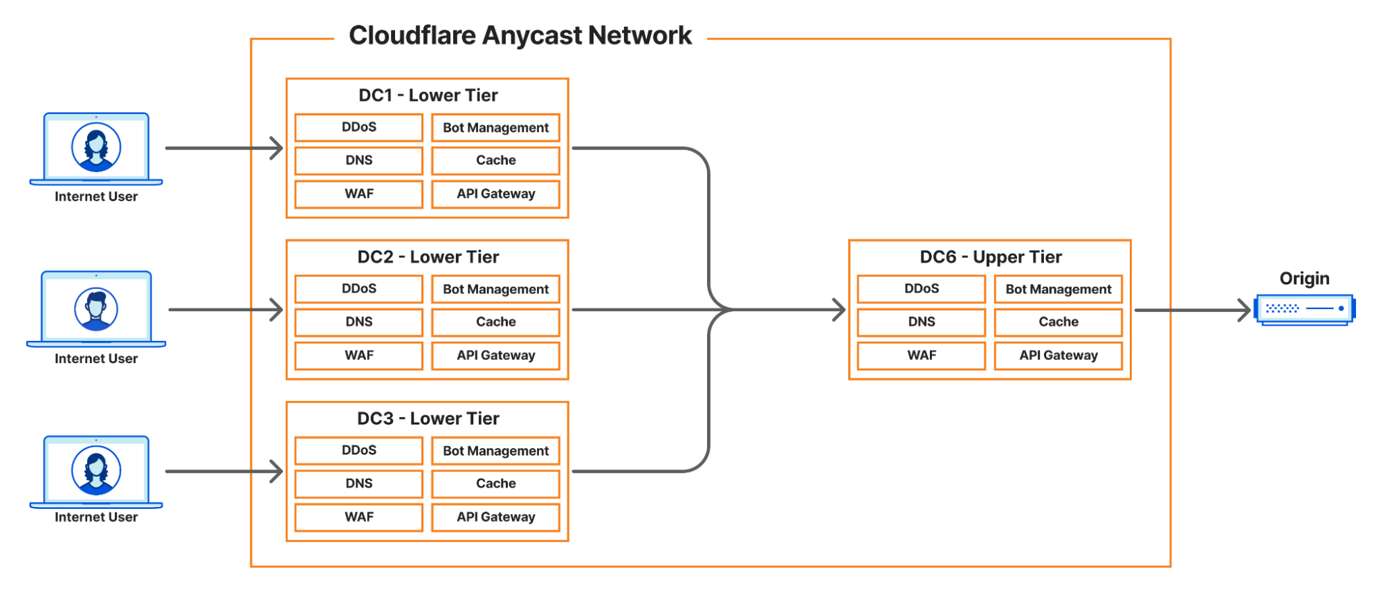
Describing the full scope of the architecture is out of scope of this article, however, we can provide a basic outline:
Internet User makes a request to pull an asset
Cloudflare infrastructure routes that request to a handler
Handler machine returns cached asset, or if miss
Handler machine reaches to origin server (owned by a customer) to pull the requested asset
The particularly interesting part is the cache miss case. When a very popular origin has an uncached asset that many Internet Users are trying to access at once, we may make upwards of: 50k TCP unicast connections to a single destination.
That is a lot of connections! We have strategies in place to limit the impact of this or avoid this problem altogether. But in these rare cases when it occurs, we will then balance these connections over two source IPv4 addresses.
Our goal is to remove the load balancing and prefer one IPv4 address. To do that, we need to understand the performance impact of two IPv4 addresses vs one.
TCP connect() performance of two source IPv4 addresses vs one IPv4 address
We leveraged a tool called wrk, and modified it to distribute connections over multiple source IP addresses. Then we ran a workload of 70k connections over 48 threads for a period of time.
During the test we measured the function tcp_v4_connect() with the BPF BCC libbpf-tool funclatency tool to gather latency metrics as time progresses.
Note that throughout the rest of this article, all the numbers are specific to a single machine with no production traffic. We are making the assumption that if we can improve a worse case scenario in an algorithm with a best case machine, that the results could be extrapolated to production. Lock contention was specifically taken out of the equation, but will have production implications.
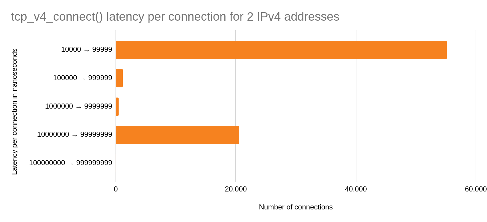
Two IPv4 addresses
The y-axis are buckets of nanoseconds in powers of ten. The x-axis represents the number of connections made per bucket. Therefore, more connections in a lower power of ten buckets is better.
We can see that the majority of the connections occur in the fast case with roughly ~20k in the slow case. We should expect this bimodal to increase over time due to wrk continuously closing and establishing connections.
Now let us look at the performance of one IPv4 address under the same conditions.
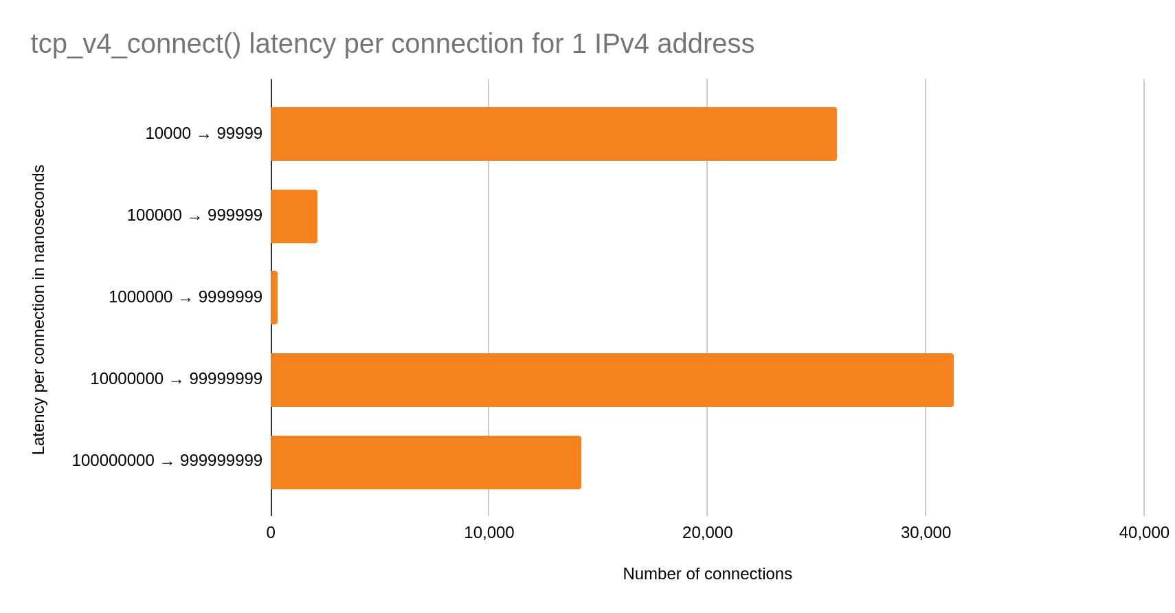
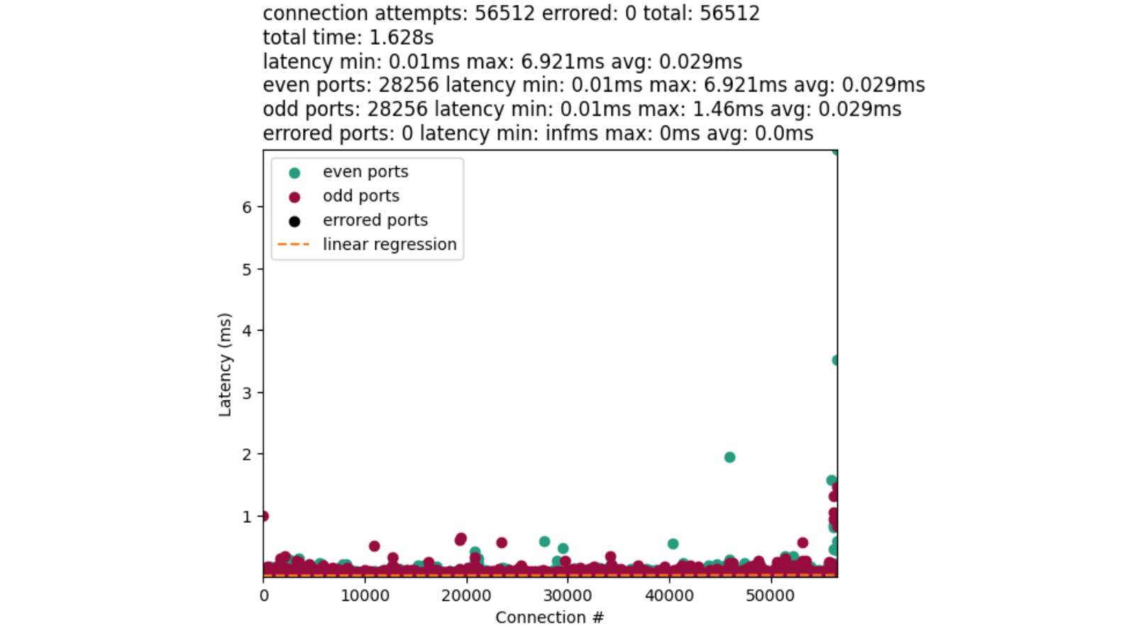
One IPv4 address
In this case, the bimodal distribution is even more pronounced. Over half of the total connections are in the slow case than in the fast! We may conclude that simply switching to one IPv4 address for cache egress is going to introduce significant latency on our connect() syscalls.
The next logical step is to figure out where this bottleneck is happening.
Port selection is not what you think it is
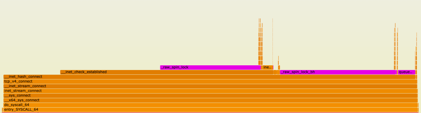
To investigate this, we first took a flame graph of a production machine:
Flame graphs depict a run-time function call stack of a system. Y-axis depicts call-stack depth, and x-axis depicts a function name in a horizontal bar that represents the amount of times the function was sampled. Checkout this in-depth guide about flame graphs for more details.
Most of the samples are taken in the function __inet_hash_connect(). We can see that there are also many samples for __inet_check_established() with some lock contention sampled between. We have a better picture of a potential bottleneck, but we do not have a consistent test to compare against.
Wrk introduces a bit more variability than we would like to see. Still focusing on the function tcp_v4_connect(), we performed another synthetic test with a homegrown benchmark tool to test one IPv4 address. A tool such as stress-ng may also be used, but some modification is necessary to implement the socket option IP_LOCAL_PORT_RANGE. There is more about that socket option later.
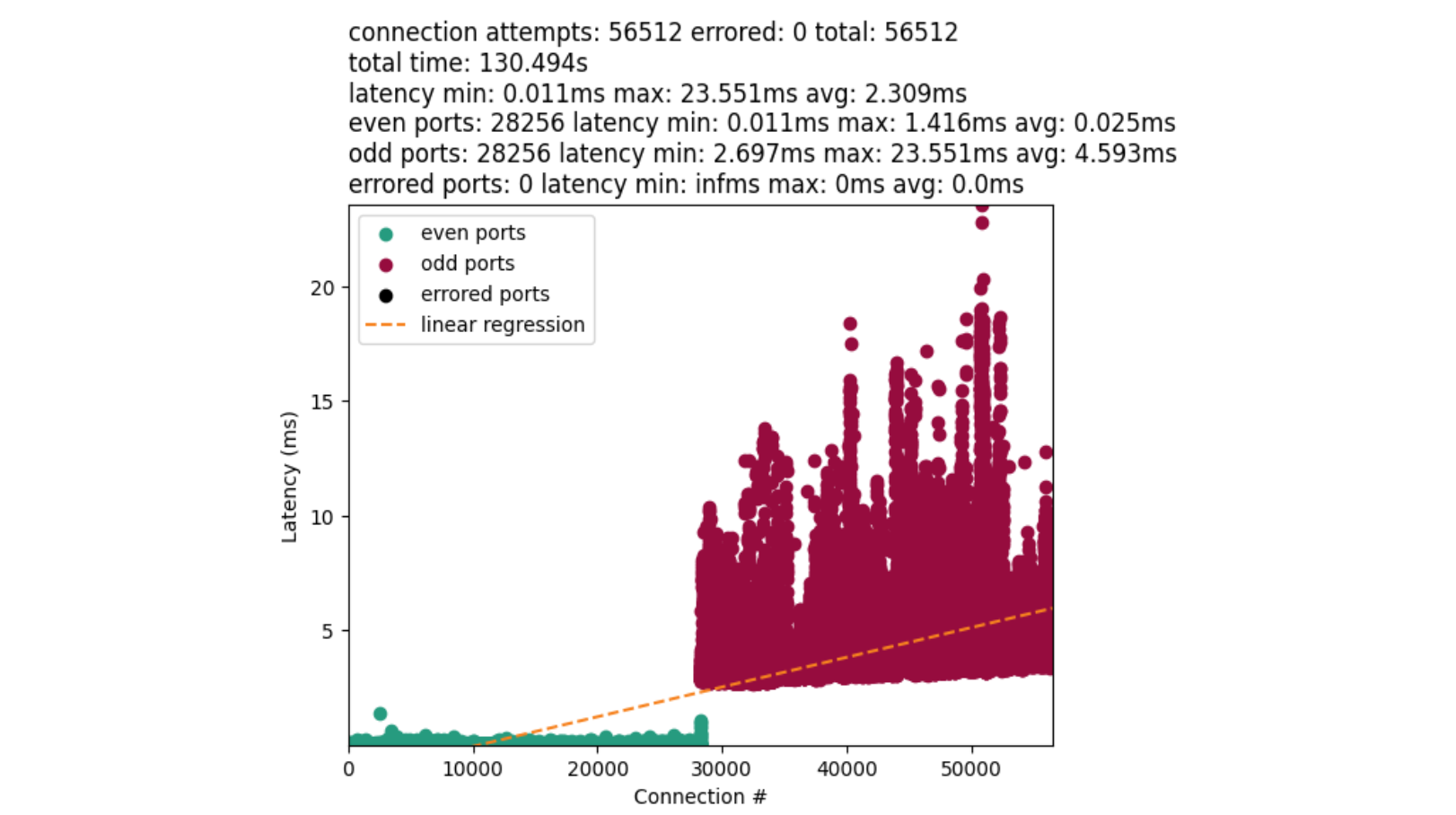
We are now going to ensure a deterministic amount of connections, and remove lock contention from the problem. The result is something like this:
On the y-axis we measured the latency between the start and end of a connect() syscall. The x-axis denotes when a connect() was called. Green dots are even numbered ports, and red dots are odd numbered ports. The orange line is a linear-regression on the data.
The disparity between the average time for port allocation between even and odd ports provides us with a major clue. Connections with odd ports are found significantly slower than the even. Further, odd ports are not interleaved with earlier connections. This implies we exhaust our even ports before attempting the odd. The chart also confirms our bimodal distribution.
__inet_hash_connect()
At this point we wanted to understand this split a bit better. We know from the flame graph and the function __inet_hash_connect() that this holds the algorithm for port selection. For context, this function is responsible for associating the socket to a source port in a late bind. If a port was previously provided with bind(), the algorithm just tests for a unique TCP 4-tuple (src ip, src port, dest ip, dest port) and ignores port selection.
Before we dive in, there is a little bit of setup work that happens first. Linux first generates a time-based hash that is used as the basis for the starting port, then adds randomization, and then puts that information into an offset variable. This is always set to an even integer.
   offset &= ~1U;

other_parity_scan:
    port = low + offset;
    for (i = 0; i < remaining; i += 2, port += 2) {
        if (unlikely(port >= high))
            port -= remaining;

        inet_bind_bucket_for_each(tb, &head->chain) {
            if (inet_bind_bucket_match(tb, net, port, l3mdev)) {
                if (!check_established(death_row, sk, port, &tw))
                    goto ok;
                goto next_port;
            }
        }
    }

    offset++;
    if ((offset & 1) && remaining > 1)
        goto other_parity_scan;
Then in a nutshell: loop through one half of ports in our range (all even or all odd ports) before looping through the other half of ports (all odd or all even ports respectively) for each connection. Specifically, this is a variation of the Double-Hash Port Selection Algorithm. We will ignore the bind bucket functionality since that is not our main concern.
Depending on your port range, you either start with an even port or an odd port. In our case, our low port, 9024, is even. Then the port is picked by adding the offset to the low port:
If low was odd, we will have an odd starting port because odd + even = odd.
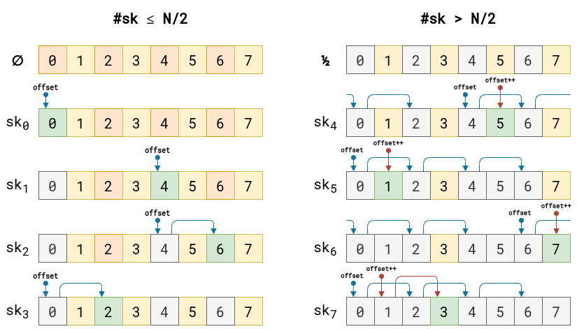
There is a bit too much going on in the loop to explain in text. I have an example instead:
This example is bound by 8 ports and 8 possible connections. All ports start unused. As a port is used up, the port is grayed out. Green boxes represent the next chosen port. All other colors represent open ports. Blue arrows are even port iterations of offset, and red are the odd port iterations of offset. Note that the offset is randomly picked, and once we cross over to the odd range, the offset is incremented by one.
For each selection of a port, the algorithm then makes a call to the function check_established() which dereferences __inet_check_established(). This function loops over sockets to verify that the TCP 4-tuple is unique. The takeaway is that the socket list in the function is usually smaller than not. This grows as more unique TCP 4-tuples are introduced to the system. Longer socket lists may slow down port selection eventually. We have a blog post that dives into the socket list and port uniqueness criteria.
At this point, we can summarize that the odd/even port split is what is causing our performance bottleneck. And during the investigation, it was not obvious to me (or even maybe you) why the offset was initially calculated the way it was, and why the odd/even port split was introduced. After some git-archaeology the decisions become more clear.
Security considerations
Port selection has been shown to be used in device fingerprinting in the past. This led the authors to introduce more randomization into the initial port selection. Prior, ports were predictably picked solely based on their initial hash and a salt value which does not change often. This helps with explaining the offset, but does not explain the split.
Why the even/odd split?
Prior to this patch and that patch, services may have conflicts between the connect() and bind() heavy workloads. Thus, to avoid those conflicts, the split was added. An even offset was chosen for the connect() workloads, and an odd offset for the bind() workloads. However, we can see that the split works great for connect() workloads that do not exceed one half of the allotted port range.
Now we have an explanation for the flame graph and charts. So what can we do about this?
User space solution (kernel < 6.8)
We have a couple of strategies that would work best for us. Infrastructure or architectural strategies are not considered due to significant development effort. Instead, we prefer to tackle the problem where it occurs.
Select, test, repeat
For the “select, test, repeat” approach, you may have code that ends up looking like this:
sys = get_ip_local_port_range()
estab = 0
i = sys.hi
while i >= 0:
    if estab >= sys.hi:
        break

    random_port = random.randint(sys.lo, sys.hi)
    connection = attempt_connect(random_port)
    if connection is None:
        i += 1
        continue

    i -= 1
    estab += 1
The algorithm simply loops through the system port range, and randomly picks a port each iteration. Then test that the connect() worked. If not, rinse and repeat until range exhaustion.
This approach is good for up to ~70-80% port range utilization. And this may take roughly eight to twelve attempts per connection as we approach exhaustion. The major downside to this approach is the extra syscall overhead on conflict. In order to reduce this overhead, we can consider another approach that allows the kernel to still select the port for us.
Select port by random shifting range
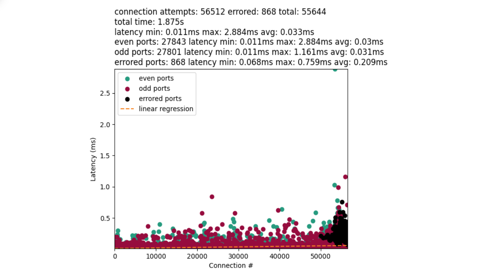
This approach leverages the IP_LOCAL_PORT_RANGE socket option. And we were able to achieve performance like this:
That is much better! The chart also introduces black dots that represent errored connections. However, they have a tendency to clump at the very end of our port range as we approach exhaustion. This is not dissimilar to what we may see in “select, test, repeat”.
We first fetch the system’s local port range, define a custom port range, and then randomly shift the custom range within the system range. Introducing this randomization helps the kernel to start port selection randomly at an odd or even port. Then reduces the loop search space down to the range of the custom window.
We tested with a few different window sizes, and determined that a five hundred or one thousand size works fairly well for our port range:
Window size
Errors
Total test time
Connections/second
500
868
~1.8 seconds
~30,139
1,000
1,129
~2 seconds
~27,260
5,000
4,037
~6.7 seconds
~8,405
10,000
6,695
~17.7 seconds
~3,183
As the window size increases, the error rate increases. That is because a larger window provides less random offset opportunity. A max window size of 56,512 is no different from using the kernels default behavior. Therefore, a smaller window size works better. But you do not want it to be too small either. A window size of one is no different from “select, test, repeat”.
In kernels >= 6.8, we can do even better.
Kernel solution (kernel >= 6.8)
A new patch was introduced that eliminates the need for the window shifting. This solution is going to be available in the 6.8 kernel.
Instead of picking a random window offset for setsockopt(IPPROTO_IP, IP_LOCAL_PORT_RANGE, …), like in the previous solution, we instead just pass the full system port range to activate the solution. The code may look something like this:
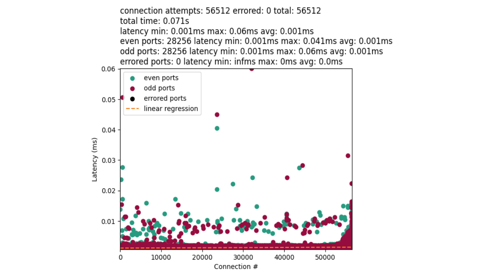
Setting IP_LOCAL_PORT_RANGE option is what tells the kernel to use a similar approach to “select port by random shifting range” such that the start offset is randomized to be even or odd, but then loops incrementally rather than skipping every other port. We end up with results like this:
The performance of this approach is quite comparable to our user space implementation. Albeit, a little faster. Due in part to general improvements, and that the algorithm can always find a port given the full search space of the range. Then there are no cycles wasted on a potentially filled sub-range.
These results are great for TCP, but what about other protocols?
Other protocols & connect()
It is worth mentioning at this point that the algorithms used for the protocols are mostly the same for IPv4 & IPv6. Typically, the key difference is how the sockets are compared to determine uniqueness and where the port search happens. We did not compare performance for all protocols. But it is worth mentioning some similarities and differences with TCP and a couple of others.
DCCP
The DCCP protocol leverages the same port selection algorithm as TCP. Therefore, this protocol benefits from the recent kernel changes. It is also possible the protocol could benefit from our user space solution, but that is untested. We will let the reader exercise DCCP use-cases.
UDP & UDP-Lite
UDP leverages a different algorithm found in the function udp_lib_get_port(). Similar to TCP, the algorithm will loop over the whole port range space incrementally. This is only the case if the port is not already supplied in the bind() call. The key difference between UDP and TCP is that a random number is generated as a step variable. Then, once a first port is identified, the algorithm loops on that port with the random number. This relies on an uint16_t overflow to eventually loop back to the chosen port. If all ports are used, increment the port by one and repeat. There is no port splitting between even and odd ports.
The best comparison to the TCP measurements is a UDP setup similar to:
sk = socket(AF_INET, SOCK_DGRAM)
sk.bind((src_ip, 0))
sk.connect((dest_ip, dest_port))
And the results should be unsurprising with one IPv4 source address:
UDP fundamentally behaves differently from TCP. And there is less work overall for port lookups. The outliers in the chart represent a worst-case scenario when we reach a fairly bad random number collision. In that case, we need to more-completely loop over the ephemeral range to find a port.
UDP has another problem. Given the socket option SO_REUSEADDR, the port you get back may conflict with another UDP socket. This is in part due to the function udp_lib_lport_inuse() ignoring the UDP 2-tuple (src ip, src port) check given the socket option. When this happens you may have a new socket that overwrites a previous. Extra care is needed in that case. We wrote more in depth about these cases in a previous blog post.
In summary
Cloudflare can make a lot of unicast egress connections to origin servers with popular uncached assets. To avoid port-resource exhaustion, we balance the load over a couple of IPv4 source addresses during those peak times. Then we asked: “what is the performance impact of one IPv4 source address for our connect()-heavy workloads?”. Port selection is not only difficult to get right, but is also a performance bottleneck. This is evidenced by measuring connect() latency with a flame graph and synthetic workloads. That then led us to discovering TCP’s quirky port selection process that loops over half your ephemeral ports before the other for each connect().
We then proposed three solutions to solve the problem outside of adding more IP addresses or other architectural changes: “select, test, repeat”, “select port by random shifting range”, and an IP_LOCAL_PORT_RANGE socket option solution in newer kernels. And finally closed out with other protocol honorable mentions and their quirks.
Do not take our numbers! Please explore and measure your own systems. With a better understanding of your workloads, you can make a good decision on which strategy works best for your needs. Even better if you come up with your own strategy!
This paper discusses the protocol used for electing the Doge of Venice between 1268 and the end of the Republic in 1797. We will show that it has some useful properties that in addition to being interesting in themselves, also suggest that its fundamental design principle is worth investigating for application to leader election protocols in computer science. For example, it gives some opportunities to minorities while ensuring that more popular candidates are more likely to win, and offers some resistance to corruption of voters.
The most obvious feature of this protocol is that it is complicated and would have taken a long time to carry out. We will also advance a hypothesis as to why it is so complicated, and describe a simplified protocol with very similar properties.
And the conclusion:
Schneier has used the phrase “security theatre” to describe public actions which do not increase security, but which are designed to make the public think that the organization carrying out the actions is taking security seriously. (He describes some examples of this in response to the 9/11 suicide attacks.) This phrase is usually used pejoratively. However, security theatre has positive aspects too, provided that it is not used as a substitute for actions that would actually improve security. In the context of the election of the Doge, the complexity of the protocol had the effect that all the oligarchs took part in a long, involved ritual in which they demonstrated individually and collectively to each other that they took seriously their responsibility to try to elect a Doge who would act for the good of Venice, and also that they would submit to the rule of the Doge after he was elected. This demonstration was particularly important given the disastrous consequences in other Mediaeval Italian city states of unsuitable rulers or civil strife between different aristocratic factions.
It would have served, too, as commercial brand-building for Venice, reassuring the oligarchs’ customers and trading partners that the city was likely to remain stable and business-friendly. After the election, the security theatre continued for several days of elaborate processions and parties. There is also some evidence of security theatre outside the election period. A 16th century engraving by Mateo Pagan depicting the lavish parade which took place in Venice each year on Palm Sunday shows the balotino in the parade, in a prominent position—next to the Grand Chancellor—and dressed in what appears to be a special costume.
I like that this paper has been accepted at a cybersecurity conference.
And, for the record, I have written about the positive aspects of security theater.
On Tuesday, March 28, 2023, the US Government will launch the Summit for Democracy 2023, following up on the inaugural Summit for Democracy 2021. The Summit is co-hosted by the United States, Costa Rica, Zambia, the Netherlands, and South Korea. Cloudflare is proud to participate in and contribute commitments to the Summit because we believe that everyone should have access to an Internet that is faster, more reliable, more private, and more secure. We work to ensure that the responsibility to respect human rights is embedded throughout our business functions. Cloudflare’s mission — to help build a better Internet — reflects a long-standing belief that we can help make the Internet better for everyone.
Our mission and core values dovetail with the Summit’s goals of strengthening democratic governance, respect for human rights and human rights defenders, and working in partnership to strengthen respect for these values. As we have written about before, access to the Internet allows activists and human rights defenders to expose abuses across the globe, allows collective causes to grow into global movements, and provides the foundation for large-scale organizing for political and social change in ways that have never been possible before.
What is the Summit for Democracy?
In December 2021, in an effort to respond to challenges to democracy worldwide, the United States held the first ever global Summit for Democracy. The Summit provided an opportunity to strengthen collaboration between democracies around the world and address common challenges from authoritarian threats. The United States invited over 100 countries plus the President of the European Commission and the United Nations Secretary-General. The Summit focused on three key themes: (1) defending against authoritarianism; (2) addressing and fighting corruption; and (3) promoting respect for human rights, and gave participants an opportunity to announce commitments, reforms, and initiatives to defend democracy and human rights. The Summit was followed by a Year of Action, during which governments implemented their commitments to the Summit.
The 2023 Summit will focus more directly on partnering with the private sector to promote an affirmative vision for technology by countering the misuse of technology and shaping emerging technologies so that they strengthen democracy and human rights, which Cloudflare supports in theory and in practice.
The three-day Summit will highlight the importance of the private sector’s role in responding to challenges to democracy. The first day of the Summit is the Thematic Day, where Cabinet-level officials, the private sector and civil society organizations will spotlight key Summit themes. On the second day of the Summit, the Plenary Day, the five co-hosts will each host a high-level plenary session. On the final day of the Summit, Co-Host Event Day, each of the co-hosts will lead high-level regional conversations with partners from government, civil society, and the private sector.
Cloudflare will be participating in the Thematic Day and the Co-Host Event Day in Washington, DC, in addition to other related events.
Cloudflare answered the United States’s call to action and made commitments to (1) help democratize post-quantum cryptography; (2) work with researchers to share data on Internet censorship and shutdowns; and (3) engage with civil society on Internet protocols and the application of privacy-enhancing technologies.
Democratizing post-quantum cryptography by including it for free, by default
At Cloudflare, we believe to enhance privacy as a human right the most advanced cryptography needs to be available to everyone, free of charge, forever. Cloudflare has committed to including post-quantum cryptography for free by default to all customers – including individual web developers, small businesses, non-profits, and governments. In particular, this will benefit at-risk groups using Cloudflare services like humanitarian organizations, human rights defenders, and journalists through Project Galileo, as well as state and local government election websites through the Athenian Project, to help secure their websites, APIs, cloud tools and remote employees against future threats.
We believe everyone should have access to the next era of cybersecurity standards–instantly and for free. To that end, Cloudflare will also publish vendor-neutral roadmaps based on NIST standards to help businesses secure any connections that are not protected by Cloudflare. We hope that others will follow us in making their implementations of post-quantum cryptography free so that we can create a secure and private Internet without a “quantum” up-charge. More details about our commitment is here and here.
Working with researchers to better document Internet censorship and shutdowns
Cloudflare commits to working with researchers to share data about Internet shutdowns and selective Internet traffic interference and to make the results of the analysis of this data public and accessible. The Cloudflare Network includes 285 locations in over 100 countries, interconnects with over 11,500 networks globally, and serves a significant portion of global Internet traffic. Cloudflare shares aggregated data on the Internet’s patterns, insights, threats and trends with the public through Cloudflare Radar, including providing alerts and data to help organizations like Access Now’sKeepItOn coalition, the Freedom Online Coalition, the Internet Society, and Open Observatory of Network Interference (OONI) monitor Internet censorship and shutdowns around the world. Cloudflare commits to working with research partners to identify signatures associated with connection tampering and failures, which are believed to be caused primarily by active censorship and blocking. Cloudflare is well-positioned to observe and report on these signatures from a global perspective, and will provide access to its findings to support additional tampering detection efforts.
Engaging with civil society on Internet protocols and the development and application of privacy-enhancing technologies
Cloudflare believes that meaningful consultation with civil society is a fundamental part of building an Internet that advances human rights. As Cloudflare works with Internet standards bodies and other Internet providers on the next-generation of privacy-enhancing technologies and protocols, like protocols to encrypt Domain Name Service records and Encrypted Client Hello (ECH) and privacy enhancing technologies like OHTTP, we commit to direct engagement with civil society and human rights experts on standards and technologies that might have implications for human rights.
Cloudflare has long worked with industry partners, stakeholders, and international standards organizations to build a more private, secure, and resilient Internet for everyone. For example, Cloudflare has built privacy technologies into its network infrastructure, helped develop and deploy TLS 1.3 alongside helping lead QUIC and other Internet protocols, improve transparency around routing and public key infrastructure (PKI), and operating a public DNS resolver that supports encryption protocols. Ensuring civil society and human rights experts are able to contribute and provide feedback as part of those efforts will make certain that future development and application of privacy-enhancing technologies and protocols are consistent with human rights principles and account for human rights impacts.
Our commitments to democratizing post-quantum cryptography, working with researchers on Internet censorship and shutdowns, and engaging with civil society on Internet protocols and the development and application of privacy-preserving technologies will help to secure access to a free, open, and interconnected Internet.
Partnering to make the Summit a success
In the lead-up to the Summit, Cloudflare has been working in partnership with the US Department of State, the National Security Council, the US Agency for International Development (USAID), and various private sector and civil society partners to prepare for the Summit. As part of our involvement, we have also contributed to roundtables and discussions with the Center for Strategic and International Studies, GNI, the Design 4 Democracy Coalition, and the Freedom Online Coalition. Cloudflare is also participating in official meetings and side events including at the Carnegie Endowment for International Peace and the Council on Foreign Relations.
In addition to the official Summit events, there are a wide range of events organized by civil society which the Accountability Lab has created a website to highlight. Separately, on Monday, March 27 the Global Democracy Coalition convened a Partners Day to organize civil society and other non-governmental events. Many of these events are being held by some of our Galileo partners like the National Democratic Institute, the International Republican Institute, Freedom House, and the Council of Europe.
Cloudflare is grateful for all of the hard work that our partners in government, civil society, and the private sector have done over the past few months to make this Summit a success. At a time where we are seeing increasing challenges to democracy and the struggle for human rights around the world, maintaining a secure, open, Internet is critical. Cloudflare is proud of our participation in the Summit and in the commitments we are making to help advance human rights. We look forward to continuing our engagement in the Summit partnership to fulfill our mission to help build a better Internet.
If you’re running a privacy-oriented application or service on the Internet, your options to provably protect users’ privacy are limited. You can minimize logs and data collection but even then, at a network level, every HTTP request needs to come from somewhere. Information generated by HTTP requests, like users’ IP addressesand TLS fingerprints, can be sensitive especially when combined with application data.
Meaningful improvements to your users’ privacy require a change in how HTTP requests are sent from client devices to the server that runs your application logic. This was the motivation for Privacy Gateway: a service that relays encrypted HTTP requests and responses between a client and application server. With Privacy Gateway, Cloudflare knows where the request is coming from, but not what it contains, and applications can see what the request contains, but not where it comes from. Neither Cloudflare nor the application server has the full picture, improving end-user privacy.
We recently deployed Privacy Gateway for Flo Health, a period tracking app, for the launch of their Anonymous Mode. With Privacy Gateway in place, all request data for Anonymous Mode users is encrypted between the app user and Flo, which prevents Flo from seeing the IP addresses of those users and Cloudflare from seeing the contents of that request data.
With Privacy Gateway in place, several other privacy-critical applications are possible:
Browser developers can collect user telemetry in a privacy-respecting manner– what extensions are installed, what defaults a user might have changed — while removing what is still a potentially personal identifier (the IP address) from that data.
Users can visit a healthcare site to report a Covid-19 exposure without worrying that the site is tracking their IP address and/or location.
The main innovation in the Oblivious HTTP standard – beyond a basic proxy service – is that these messages are encrypted to the application’s server, such that Privacy Gateway learns nothing of the application data beyond the source and destination of each message.
Privacy Gateway enables application developers and platforms, especially those with strong privacy requirements, to build something that closely resembles a “Mixnet”: an approach to obfuscating the source and destination of a message across a network. To that end, Privacy Gateway consists of three main components:
Client: the user’s device, or any client that’s configured to forward requests to Privacy Gateway.
Privacy Gateway: a service operated by Cloudflare and designed to relay requests between the Client and the Gateway, without being able to observe the contents within.
Application server: the origin or application web server responsible for decrypting requests from clients, and encrypting responses back.
If you were to imagine request data as the contents of the envelope (a letter) and the IP address and request metadata as the address on the outside, with Privacy Gateway, Cloudflare is able to see the envelope’s address and safely forward it to its destination without being able to see what’s inside.
An Oblivious HTTP transaction using Privacy Gateway
In slightly more detail, the data flow is as follows:
Client encapsulates an HTTP request using the public key of the application server, and sends it to Privacy Gateway over an HTTPS connection.
Privacy Gateway forwards the request to the server over its own, separate HTTPS connection with the application server.
The application server decapsulates the request, forwarding it to the target server which can produce the response.
The application server returns an encapsulated response to Privacy Gateway, which then forwards the result to the client. As specified in the protocol, requests from the client to the server are encrypted using HPKE, a state-of-the-art standard for public key encryption – which you can read more about here. We’ve taken additional measures to ensure that OHTTP’s use of HPKE is secure by conducting a formal analysis of the protocol, and we expect to publish a deeper analysis in the coming weeks.
How Privacy Gateway improves end-user privacy
This interaction offers two types of privacy, which we informally refer to as request privacy and client privacy.
Request privacy means that the application server does not learn information that would otherwise be revealed by an HTTP request, such as IP address, geolocation, TLS and HTTPS fingerprints, and so on. Because Privacy Gateway uses a separate HTTPS connection between itself and the application server, all of this per-request information revealed to the application server represents that of Privacy Gateway, not of the client. However, developers need to take care to not send personally identifying information in the contents of requests. If the request, once decapsulated, includes information like users’ email, phone number, or credit card info, for example, Privacy Gateway will not meaningfully improve privacy.
Client privacy is a stronger notion. Because Cloudflare and the application server are not colluding to share individual user’s data, from the server’s perspective, each individual transaction came from some unknown client behind Privacy Gateway. In other words, a properly configured Privacy Gateway deployment means that applications cannot link any two requests to the same client. In particular, with Privacy Gateway, privacy loves company. If there is only one end-user making use of Privacy Gateway, then it only provides request privacy (since the client IP address remains hidden from the Gateway). It would not provide client privacy, since the server would know that each request corresponds to the same, single client. Client privacy requires that there be many users of the system, so the application server cannot make this determination.
To better understand request and client privacy, consider the following HTTP request between a client and server:
Normal HTTP configuration with a client anonymity set of size 1
If a client connects directly to the server (or “Gateway” in OHTTP terms), the server is likely to see information about the client, including the IP address, TLS cipher used, and a degree of location data based on that IP address:
- ipAddress: 192.0.2.33 # the client’s real IP address
- ASN: 7922
- AS Organization: Comcast Cable
- tlsCipher: AEAD-CHACHA20-POLY1305-SHA256 # potentially unique
- tlsVersion: TLSv1.3
- Country: US
- Region: California
- City: Campbell
There’s plenty of sensitive information here that might be unique to the end-user. In other words, the connection offers neither request nor client privacy.
With Privacy Gateway, clients do not connect directly to the application server itself. Instead, they connect to Privacy Gateway, which in turn connects to the server. This means that the server only observes connections from Privacy Gateway, not individual connections from clients, yielding a different view:
- ipAddress: 104.16.5.5 # a Cloudflare IP
- ASN: 13335
- AS Organization: Cloudflare
- tlsCipher: ECDHE-ECDSA-AES128-GCM-SHA256 # shared across several clients
- tlsVersion: TLSv1.3
- Country: US
- Region: California
- City: Los Angeles
Privacy Gateway configuration with a client anonymity set of size k
This is request privacy. All information about the client’s location and identity are hidden from the application server. And all details about the application data are hidden from Privacy Gateway. For sensitive applications and protocols like DNS, keeping this metadata separate from the application data is an important step towards improving end-user privacy.
Moreover, applications should take care to not reveal sensitive, per-client information in their individual requests. Privacy Gateway cannot guarantee that applications do not send identifying info – such as email addresses, full names, etc – in request bodies, since it cannot observe plaintext application data. Applications which reveal user identifying information in requests may violate client privacy, but not request privacy. This is why – unlike our full application-level Privacy Proxy product – Privacy Gateway is not meant to be used as a generic proxy-based protocol for arbitrary applications and traffic. It is meant to be a special purpose protocol for sensitive applications, including DNS (as is evidenced by Oblivious DNS-over-HTTPS), telemetry data, or generic API requests as discussed above.
Integrating Privacy Gateway into your application
Integrating with Privacy Gateway requires applications to implement the client and server side of the OHTTP protocol. Let’s walk through what this entails.
Server Integration
The server-side part of the protocol is responsible for two basic tasks:
Publishing a public key for request encapsulation; and
Decrypting encapsulated client requests, processing the resulting request, and encrypting the corresponding response.
A public encapsulation key, called a key configuration, consists of a key identifier (so the server can support multiple keys at once for rotation purposes), cryptographic algorithm identifiers for encryption and decryption, and a public key:
HPKE Symmetric Algorithms {
  HPKE KDF ID (16),
  HPKE AEAD ID (16),
}

OHTTP Key Config {
  Key Identifier (8),
  HPKE KEM ID (16),
  HPKE Public Key (Npk * 8),
  HPKE Symmetric Algorithms Length (16),
  HPKE Symmetric Algorithms (32..262140),
}
Clients need this public key to create their request, and there are lots of ways to do this. Servers could fix a public key and then bake it into their application, but this would require a software update to rotate the key. Alternatively, clients could discover the public key some other way. Many discovery mechanisms exist and vary based on your threat model – see this document for more details. To start, a simple approach is to have clients fetch the public key directly from the server over some API. Below is a snippet of the API that our open source OHTTP server provides:
func (s *GatewayResource) configHandler(w http.ResponseWriter, r *http.Request) {
	config, err := s.Gateway.Config(s.keyID)
	if err != nil {
		http.Error(w, http.StatusText(http.StatusInternalServerError), http.StatusInternalServerError)
		return
	}
	w.Write(config.Marshal())
}
Once public key generation and distribution is solved, the server then needs to handle encapsulated requests from clients. For each request, the server needs to decrypt the request, translate the plaintext to a corresponding HTTP request that can be resolved, and then encrypt the resulting response back to the client.
Open source OHTTP libraries typically offer functions for request decryption and response encryption, whereas plaintext translation from binary HTTP to an HTTP request is handled separately. For example, our open source server delegates this translation to a different library that is specific to how Go HTTP requests are represented in memory. In particular, the function to translate from a plaintext request to a Go HTTP request is done with a function that has the following signature:
While there exist several open source libraries that one can use to implement OHTTP server support, we’ve packaged all of it up in our open source server implementation available here. It includes instructions for building, testing, and deploying to make it easy to get started.
Client integration
Naturally, the client-side behavior of OHTTP mirrors that of the server. In particular, the client must:
Discover or obtain the server public key; and
Encode and encrypt HTTP requests, send them to Privacy Gateway, and decrypt and decode the HTTP responses.
Discovery of the server public key depends on the server’s chosen deployment model. For example, if the public key is available over an API, clients can simply fetch it directly:
Encoding, encrypting, decrypting, and decoding are again best handled by OHTTP libraries when available. With these functions available, building client support is rather straightforward. A trivial example Go client using the library functions linked above is as follows:
A standalone client like this isn’t likely very useful to you if you have an existing application. To help integration into your existing application, we created a sample OHTTP client library that’s compatible with iOS and macOS applications. Additionally, if there’s language or platform support you would like to see to help ease integration on either or the client or server side, please let us know!
Interested?
Privacy Gateway is currently in early access – available to select privacy-oriented companies and partners. If you’re interested, please get in touch.
The Internet, far from being just a series of tubes, is a huge, incredibly complex, decentralized system. Every action and interaction in the system is enabled by a complicated mass of protocols woven together to accomplish their task, each handing off to the next like trapeze artists high above a virtual circus ring. Stop to think about details, and it is a marvel.
Consider one of the simplest tasks enabled by the Internet: Sending a message from sender to receiver.
The location (address) of a receiver is discovered using DNS, a connection between sender and receiver is established using a transport protocol like TCP, and (hopefully!) secured with a protocol like TLS. The sender’s message is encoded in a format that the receiver can recognize and parse, like HTTP, because the two disparate parties need a common language to communicate. Then, ultimately, the message is sent and carried in an IP datagram that is forwarded from sender to receiver based on routes established with BGP.
Even an explanation this dense is laughably oversimplified. For example, the four protocols listed are just the start, and ignore many others with acronyms of their own. The truth is that things are complicated. And because things are complicated, how these protocols and systems interact and influence the user experience on the Internet is complicated. Extra round trips to establish a secure connection increase the amount of time before useful work is done, harming user performance. The use of unauthenticated or unencrypted protocols reveals potentially sensitive information to the network or, worse, to malicious entities, which harms user security and privacy. And finally, consolidation and centralization — seemingly a prerequisite for reducing costs and protecting against attacks — makes it challenging to provide high availability even for essential services. (What happens when that one system goes down or is otherwise unavailable, or to extend our earlier metaphor, when a trapeze isn’t there to catch?)
These four properties — performance, security, privacy, and availability — are crucial to the Internet. At Cloudflare, and especially in the Cloudflare Research team, where we use all these various protocols, we’re committed to improving them at every layer in the stack. We work on problems as diverse as helping network security and privacy with TLS 1.3 and QUIC, improving DNS privacy via Oblivious DNS-over-HTTPS, reducing end-user CAPTCHA annoyances with Privacy Pass and Cryptographic Attestation of Personhood (CAP), performing Internet-wide measurements to understand how things work in the real world, and much, much more.
Above all else, these projects are meant to do one thing: focus beyond the horizon to help build a better Internet. We do that by developing, advocating, and advancing open standards for the many protocols in use on the Internet, all backed by implementation, experimentation, and analysis.
Standards
The Internet is a network of interconnected autonomous networks. Computers attached to these networks have to be able to route messages to each other. However, even if we can send messages back and forth across the Internet, much like the storied Tower of Babel, to achieve anything those computers have to use a common language, a lingua franca, so to speak. And for the Internet, standards are that common language.
Many of the parts of the Internet that Cloudflare is interested in are standardized by the IETF, which is a standards development organization responsible for producing technical specifications for the Internet’s most important protocols, including IP, BGP, DNS, TCP, TLS, QUIC, HTTP, and so on. The IETF’s mission is:
> to make the Internet work better by producing high-quality, relevant technical documents that influence the way people design, use, and manage the Internet.
Our individual contributions to the IETF help further this mission, especially given our role on the Internet. We can only do so much on our own to improve the end-user experience. So, through standards, we engage with those who use, manage, and operate the Internet to achieve three simple goals that lead to a better Internet:
1. Incrementally improve existing and deployed protocols with innovative solutions;
2. Provide holistic solutions to long-standing architectural problems and enable new use cases; and
3. Identify key problems and help specify reusable, extensible, easy-to-implement abstractions for solving them.
Below, we’ll give an example of how we helped achieve each goal, touching on a number of important technical specifications produced in recent years, including DNS-over-HTTPS, QUIC, and (the still work-in-progress) TLS Encrypted Client Hello.
Incremental innovation: metadata privacy with DoH and ECH
The Internet is not only complicated — it is leaky. Metadata seeps like toxic waste from nearly every protocol in use, from DNS to TLS, and even to HTTP at the application layer.
One critically important piece of metadata that still leaks today is the name of the server that clients connect to. When a client opens a connection to a server, it reveals the name and identity of that server in many places, including DNS, TLS, and even sometimes at the IP layer (if the destination IP address is unique to that server). Linking client identity (IP address) to target server names enables third parties to build a profile of per-user behavior without end-user consent. The result is a set of protocols that does not respect end-user privacy.
Fortunately, it’s possible to incrementally address this problem without regressing security. For years, Cloudflare has been working with the standards community to plug all of these individual leaks through separate specialized protocols:
DNS-over-HTTPS encrypts DNS queries between clients and recursive resolvers, ensuring only clients and trusted recursive resolvers see plaintext DNS traffic.
TLS Encrypted Client Hello encrypts metadata in the TLS handshake, ensuring only the client and authoritative TLS server see sensitive TLS information.
These protocols impose a barrier between the client and server and everyone else. However, neither of them prevent the server from building per-user profiles. Servers can track users via one critically important piece of information: the client IP address. Fortunately, for the overwhelming majority of cases, the IP address is not essential for providing a service. For example, DNS recursive resolvers do not need the full client IP address to provide accurate answers, as is evidenced by the EDNS(0) Client Subnet extension. To further reduce information exposure on the web, we helped push further with two more incremental improvements:
Oblivious DNS-over-HTTPS (ODoH) uses cryptography and network proxies to break linkability between client identity (IP address) and DNS traffic, ensuring that recursive resolvers have only the minimal amount of information to provide DNS answers — the queries themselves, without any per-client information.
MASQUE is standardizing techniques for proxying UDP and IP protocols over QUIC connections, similar to the existing HTTP CONNECT method for TCP-based protocols. Generally, the CONNECT method allows clients to use services without revealing any client identity (IP address).
While each of these protocols may seem only an incremental improvement over what we have today, together, they raise many possibilities for the future of the Internet. Are DoH and ECH sufficient for end-user privacy, or are technologies like ODoH and MASQUE necessary? How do proxy technologies like MASQUE complement or even subsume protocols like ODoH and ECH? These are questions the Cloudflare Research team strives to answer through experimentation, analysis, and deployment together with other stakeholders on the Internet through the IETF. And we could not ask the questions without first laying the groundwork.
Architectural advancement: QUIC and HTTP/3
QUIC and HTTP/3 are transformative technologies. Whilst the TLS handshake forms the heart of QUIC’s security model, QUIC is an improvement beyond TLS over TCP, in many respects, including more encryption (privacy), better protection against active attacks and ossification at the network layer, fewer round trips to establish a secure connection, and generally better security properties. QUIC and HTTP/3 give us a clean slate for future innovation.
Perhaps one of QUIC’s most important contributions is that it challenges and even breaks many established conventions and norms used on the Internet. For example, the antiquated socket API for networking, which treats the network connection as an in-order bit pipe is no longer appropriate for modern applications and developers. Modern networking APIs such as Apple’s Network.framework provide high-level interfaces that take advantage of the new transport features provided by QUIC. Applications using this or even higher-level HTTP abstractions can take advantage of the many security, privacy, and performance improvements of QUIC and HTTP/3 today with minimal code changes, and without being constrained by sockets and their inherent limitations.
Another salient feature of QUIC is its wire format. Nearly every bit of every QUIC packet is encrypted and authenticated between sender and receiver. And within a QUIC packet, individual frames can be rearranged, repackaged, and otherwise transformed by the sender.
Together, these are powerful tools to help mitigate future network ossification and enable continued extensibility. (TLS’s wire format ultimately led to the middlebox compatibility mode for TLS 1.3 due to the many middlebox ossification problems that were encountered during early deployment tests.)
Exercising these features of QUIC is important for the long-term health of the protocol and applications built on top of it. Indeed, this sort of extensibility is what enables innovation.
In fact, we’ve already seen a flurry of new work based on QUIC: extensions to enable multipath QUIC, different congestion control approaches, and ways to carry data unreliably in the DATAGRAM frame.
Beyond functional extensions, we’ve also seen a number of new use cases emerge as a result of QUIC. DNS-over-QUIC is an upcoming proposal that complements DNS-over-TLS for recursive to authoritative DNS query protection. As mentioned above, MASQUE is a working group focused on standardizing methods for proxying arbitrary UDP and IP protocols over QUIC connections, enabling a number of fascinating solutions and unlocking the future of proxy and VPN technologies. In the context of the web, the WebTransport working group is standardizing methods to use QUIC as a “supercharged WebSocket” for transporting data efficiently between client and server while also depending on the WebPKI for security.
By definition, these extensions are nowhere near complete. The future of the Internet with QUIC is sure to be a fascinating adventure.
Specifying abstractions: Cryptographic algorithms and protocol design
Standards allow us to build abstractions. An ideal standard is one that is usable in many contexts and contains all the information a sufficiently skilled engineer needs to build a compliant implementation that successfully interoperates with other independent implementations. Writing a new standard is sort of like creating a new Lego brick. Creating a new Lego brick allows us to build things that we couldn’t have built before. For example, one new “brick” that’s nearly finished (as of this writing) is Hybrid Public Key Encryption (HPKE). HPKE allows us to efficiently encrypt arbitrary plaintexts under the recipient’s public key.
Mixing asymmetric and symmetric cryptography for efficiency is a common technique that has been used for many years in all sorts of protocols, from TLS to PGP. However, each of these applications has come up with their own design, each with its own security properties. HPKE is intended to be a single, standard, interoperable version of this technique that turns this complex and technical corner of protocol design into an easy-to-use black box. The standard has undergone extensive analysis by cryptographers throughout its development and has numerous implementations available. The end result is a simple abstraction that protocol designers can include without having to consider how it works under-the-hood. In fact, HPKE is already a dependency for a number of other draft protocols in the IETF, such as TLS Encrypted Client Hello, Oblivious DNS-over-HTTPS, and Message Layer Security.
Modes of Interaction
We engage with the IETF in the specification, implementation, experimentation, and analysis phases of a standard to help achieve our three goals of incremental innovation, architectural advancement, and production of simple abstractions.
Our participation in the standards process hits all four phases. Individuals in Cloudflare bring a diversity of knowledge and domain expertise to each phase, especially in the production of technical specifications. This week, we’ll have a blog about an upcoming standard that we’ve been working on for a number of years and will be sharing details about how we used formal analysis to make sure that we ruled out as many security issues in the design as possible. We work in close collaboration with people from all around the world as an investment in the future of the Internet. Open standards mean that everyone can take advantage of the latest and greatest in protocol design, whether they use Cloudflare or not.
Cloudflare’s scale and perspective on the Internet are essential to the standards process. We have experience rapidly implementing, deploying, and experimenting with emerging technologies to gain confidence in their maturity. We also have a proven track record of publishing the results of these experiments to help inform the standards process. Moreover, we open source as much of the code we use for these experiments as possible to enable reproducibility and transparency. Our unique collection of engineering expertise and wide perspective allows us to help build standards that work in a wide variety of use cases. By investing time in developing standards that everyone can benefit from, we can make a clear contribution to building a better Internet.
One final contribution we make to the IETF is more procedural and based around building consensus in the community. A challenge to any open process is gathering consensus to make forward progress and avoiding deadlock. We help build consensus through the production of running code, leadership on technical documents such as QUIC and ECH, and even logistically by chairing working groups. (Working groups at the IETF are chaired by volunteers, and Cloudflare numbers a few working group chairs amongst its employees, covering a broad spectrum of the IETF (and its related research-oriented group, the IRTF) from security and privacy to transport and applications.) Collaboration is a cornerstone of the standards process and a hallmark of Cloudflare Research, and we apply it most prominently in the standards process.
If you too want to help build a better Internet, check out some IETF Working Groups and mailing lists. All you need to start contributing is an Internet connection and an email address, so why not give it a go? And if you want to join us on our mission to help build a better Internet through open and interoperable standards, check out our openpositions, visiting researcher program, and many internship opportunities!
Our earlier blog post talked in general terms about how we work with the IETF. In this post we’re going to talk about a particular IETF project we’ve been working on, Exported Authenticators (EAs). Exported Authenticators is a new extension to TLS that we think will prove really exciting. It unlocks all sorts of fancy new authentication possibilities, from TLS connections with multiple certificates attached, to logging in to a website without ever revealing your password.
Now, you might have thought that given the innumerable hours that went into the design of TLS 1.3 that it couldn’t possibly be improved, but it turns out that there are a number of places where the design falls a little short. TLS allows us to establish a secure connection between a client and a server. The TLS connection presents a certificate to the browser, which proves the server is authorised to use the name written on the certificate, for example blog.cloudflare.com. One of the most common things we use that ability for is delivering webpages. In fact, if you’re reading this, your browser has already done this for you. The Cloudflare Blog is delivered over TLS, and by presenting a certificate for blog.cloudflare.com the server proves that it’s allowed to deliver Cloudflare’s blog.
When your browser requests blog.cloudflare.com you receive a big blob of HTML that your browser then starts to render. In the dim and distant past, this might have been the end of the story. Your browser would render the HTML, and display it. Nowadays, the web has become more complex, and the HTML your browser receives often tells it to go and load lots of other resources. For example, when I loaded the Cloudflare blog just now, my browser made 73 subrequests.
As we mentioned in our connection coalescing blog post, sometimes those resources are also served by Cloudflare, but on a different domain. In our connection coalescing experiment, we acquired certificates with a special extension, called a Subject Alternative Name (SAN), that tells the browser that the owner of the certificate can act as two different websites. Along with some further shenanigans that you can read about in our blog post, this lets us serve the resources for both the domains over a single TLS connection.
Cloudflare, however, services millions of domains, and we have millions of certificates. It’s possible to generate certificates that cover lots of domains, and in fact this is what Cloudflare used to do. We used to use so-called “cruise-liner” certificates, with dozens of names on them. But for connection coalescing this quickly becomes impractical, as we would need to know what sub-resources each webpage might request, and acquire certificates to match. We switched away from this model because issues with individual domains could affect other customers.
What we’d like to be able to do is serve as much content as possible down a single connection. When a user requests a resource from a different domain they need to perform a new TLS handshake, costing valuable time and resources. Our connection coalescing experiment showed the benefits when we know in advance what resources are likely to be requested, but most of the time we don’t know what subresources are going to be requested until the requests actually arrive. What we’d rather do is attach extra identities to a connection after it’s been established, and we know what extra domains the client actually wants. Because the TLS connection is just a transport mechanism and doesn’t understand the information being sent across it, it doesn’t actually know what domains might subsequently be requested. This is only available to higher-layer protocols such as HTTP. However, we don’t want any website to be able to impersonate another, so we still need to have strong authentication.
Exported Authenticators
Enter Exported Authenticators. They give us even more than we asked for. They allow us to do application layer authentication that’s just as strong as the authentication you get from TLS, and then tie it to the TLS channel. Now that’s a pretty complicated idea, so let’s break it down.
To understand application layer authentication we first need to explain what the application layer is. The application layer is a reference to the OSI model. The OSI model describes the various layers of abstraction we use, to make things work across the Internet. When you’re developing your latest web application you don’t want to have to worry about how light is flickered down a fibre optic cable, or even how the TLS handshake is encoded (although that’s a fascinating topic in its own right, let’s leave that for another time.)
All you want to care about is having your content delivered to your end-user, and using TLS gives you a guaranteed in-order, reliable, authenticated channel over which you can communicate. You just shove bits in one end of the pipe, and after lots of blinky lights, fancy routing, maybe a touch of congestion control, and a little decoding, *poof*, your data arrives at the end-user.
The application layer is the top of the OSI stack, and contains things like HTTP. Because the TLS handshake is lower in the stack, the application is oblivious to this process. So, what Exported Authenticators give us is the ability for the very top of the stack to reliably authenticate their partner.
The seven-layered OSI model
Now let’s jump back a bit, and discuss what we mean when we say that EAs give us authentication that’s as strong as TLS authentication. TLS, as we know, is used to create a secure connection between two endpoints, but lots of us are hazy when we try and pin down exactly what we mean by “secure”. The TLS standard makes eight specific promises, but rather than get buried in that particular ocean of weeds, let’s just pick out the one guarantee that we care about most: Peer Authentication.
Peer authentication: The client's view of the peer identity should reflect the server's identity. [...]
In other words, if the client thinks that it’s talking to example.com then it should, in fact, be talking to example.com.
What we want from EAs is that if I receive an EA then I have cryptographic proof that the person I’m talking to is the person I think I’m talking to. Now at this point you might be wondering what an EA actually looks like, and what it has to do with certificates. Well, an EA is actually a trio of messages, the first of which is a Certificate. The second is a CertificateVerify, a cryptographic proof that the sender knows the private key for the certificate. Finally there is a Finished message, which acts as a MAC, and proves the first two parts of the message haven’t been tampered with. If this structure sounds familiar to you, it’s because it’s the same structure as used by the server in the TLS handshake to prove it is the owner of the certificate.
The final piece of unpacking we need to do is explaining what we mean by tying the authentication to the TLS channel. Because EAs are an application layer construct they don’t provide any transport mechanism. So, whilst I know that the EA was created by the server I want to talk to, without binding the EA to a TLS connection I can’t be sure that I’m talking directly to the server I want.
Without protection, a malicious server can move Exported Authenticators from one connection to another.
For all I know, the TLS server I’m talking to is creating a new TLS connection to the EA Server, and relaying my request, and then returning the response. This would be very bad, because it would allow a malicious server to impersonate any server that supports EAs.
Because EAs are bound to a single TLS connection, if a malicious server copies an EA from one connection to another it will fail to verify.
EAs therefore have an extra security feature. They use the fact that every TLS connection is guaranteed to produce a unique set of keys. EAs take one of these keys and use it to construct the EA. This means that if some malicious third-party copies an EA from one TLS session to another, the recipient wouldn’t be able to validate it. This technique is called channel binding, and is another fascinating topic, but this post is already getting a bit long, so we’ll have to revisit channel binding in a future blog post.
How the sausage is made
OK, now we know what EAs do, let’s talk about how they were designed and built. EAs are going through the IETF standardisation process. Draft standards move through the IETF process starting as Internet Drafts (I-Ds), and ending up as published Requests For Comment (RFCs). RFCs are voluntary standards that underpin much of the global Internet plumbing, and not just for security protocols like TLS. RFCs define DNS, UDP, TCP, and many, many more.
The first step in producing a new IETF standard is coming up with a proposal. Designing security protocols is a very conservative business, firstly because it’s very easy to introduce really subtle bugs, and secondly, because if you do introduce a security issue, things can go very wrong, very quickly. A flaw in the design of a protocol can be especially problematic as it can be replicated across multiple independent implementations — for example the TLS renegotiation vulnerabilities reported in 2009 and the custom EC(DH) parameters vulnerability from 2012. To minimise the risks of design issues, EAs hew closely to the design of the TLS 1.3 handshake.
Security and Assurance
Before making a big change to how authentication works on the Internet, we want as much assurance as possible that we’re not going to break anything. To give us more confidence that EAs are secure, they reuse parts of the design of TLS 1.3. The TLS 1.3 design was carefully examined by dozens of experts, and underwent multiple rounds of formal analysis — more on that in a moment. Using well understood design patterns is a super important part of security protocols. Making something secure is incredibly difficult, because security issues can be introduced in thousands of ways, and an attacker only needs to find one. By starting from a well understood design we can leverage the years of expertise that went into it.
Another vital step in catching design errors early is baked into the IETF process: achieving rough consensus. Although the ins and outs of the IETF process are worthy of their own blog post, suffice it to say the IETF works to ensure that all technical objections get addressed, and even if they aren’t solved they are given due care and attention. Exported Authenticators were proposed way back in 2016, and after many rounds of comments, feedback, and analysis the TLS Working Group (WG) at the IETF has finally reached consensus on the protocol. All that’s left before the EA I-D becomes an RFC is for a final revision of the text to be submitted and sent to the RFC Editors, leading hopefully to a published standard very soon.
As we just mentioned, the WG has to come to a consensus on the design of the protocol. One thing that can hold up achieving consensus are worries about security. After the Snowden revelations there was a barrageofattacksonTLS 1.2, not to mention some even earlier attacks from academia. Changing how trust works on the Internet can be pretty scary, and the TLS WG didn’t want to be caught flat-footed. Luckily this coincided with the maturation of some tools and techniques we can use to get mathematical guarantees that a protocol is secure. This class of techniques is known as formal methods. To help ensure that people are confident in the security of EAs I performed a formal analysis.
Formal Analysis
Formal analysis is a special technique that can be used to examine security protocols. It creates a mathematical description of the protocol, the security properties we want it to have, and a model attacker. Then, aided by some sophisticated software, we create a proof that the protocol has the properties we want even in the presence of our model attacker. This approach is able to catch incredibly subtle edge cases, which, if not addressed, could lead to attacks, as has happenedbefore. Trotting out a formal analysis gives us strong assurances that we haven’t missed any horrible issues. By sticking as closely as possible to the design of TLS 1.3 we were able to repurpose much of the original analysis for EAs, giving us a big leg up in our ability to prove their security. Our EA model is available in Bitbucket, along with the proofs. You can check it out using Tamarin, a theorem prover for security protocols.
Formal analysis, and formal methods in general, give very strong guarantees that rule out entire classes of attack. However, they are not a panacea. TLS 1.3 was subject to a number of rounds of formal analysis, and yet an attack was still found. However, this attack in many ways confirms our faith in formal methods. The attack was found in a blind spot of the proof, showing that attackers have been pushed to the very edges of the protocol. As our formal analyses get more and more rigorous, attackers will have fewer and fewer places to search for attacks. As formal analysis has become more and more practical, more and more groups at the IETF have been asking to see proofs of security before standardising new protocols. This hopefully will mean that future attacks on protocol design will become rarer and rarer.
Once the EA I-D becomes an RFC, then all sorts of cool stuff gets unlocked — for example OPAQUE-EAs, which will allow us to do password-based login on the web without the server ever seeing the password! Watch this space.
Privacy and security are fundamental to Cloudflare, and we believe in and champion the use of cryptography to help provide these fundamentals for customers, end-users, and the Internet at large. In the past, we helped specify, implement, and ship TLS 1.3, the latest version of the transport security protocol underlying the web, to all of our users. TLS 1.3 vastly improved upon prior versions of the protocol with respect to security, privacy, and performance: simpler cryptographic algorithms, more handshake encryption, and fewer round trips are just a few of the many great features of this protocol.
TLS 1.3 was a tremendous improvement over TLS 1.2, but there is still room for improvement. Sensitive metadata relating to application or user intent is still visible in plaintext on the wire. In particular, all client parameters, including the name of the target server the client is connecting to, are visible in plaintext. For obvious reasons, this is problematic from a privacy perspective: Even if your application traffic to crypto.cloudflare.com is encrypted, the fact you’re visiting crypto.cloudflare.com can be quite revealing.
And so, in collaboration with other participants in the standardization community and members of industry, we embarked towards a solution for encrypting all sensitive TLS metadata in transit. The result: TLS Encrypted ClientHello (ECH), an extension to protect this sensitive metadata during connection establishment.
Last year, we described the current status of this standard and its relation to the TLS 1.3 standardization effort, as well as ECH’s predecessor, Encrypted SNI (ESNI). The protocol has come a long way since then, but when will we know when it’s ready? There are many ways by which one can measure a protocol. Is it implementable? Is it easy to enable? Does it seamlessly integrate with existing protocols or applications? In order to assess these questions and see if the Internet is ready for ECH, the community needs deployment experience. Hence, for the past year, we’ve been focused on making the protocol stable, interoperable, and, ultimately, deployable. And today, we’re pleased to announce that we’ve begun our initial deployment of TLS ECH.
What does ECH mean for connection security and privacy on the network? How does it relate to similar technologies and concepts such as domain fronting? In this post, we’ll dig into ECH details and describe what this protocol does to move the needle to help build a better Internet.
Connection privacy
For most Internet users, connections are made to perform some type of task, such as loading a web page, sending a message to a friend, purchasing some items online, or accessing bank account information. Each of these connections reveals some limited information about user behavior. For example, a connection to a messaging platform reveals that one might be trying to send or receive a message. Similarly, a connection to a bank or financial institution reveals when the user typically makes financial transactions. Individually, this metadata might seem harmless. But consider what happens when it accumulates: does the set of websites you visit on a regular basis uniquely identify you as a user? The safe answer is: yes.
This type of metadata is privacy-sensitive, and ultimately something that should only be known by two entities: the user who initiates the connection, and the service which accepts the connection. However, the reality today is that this metadata is known to more than those two entities.
Making this information private is no easy feat. The nature or intent of a connection, i.e., the name of the service such as crypto.cloudflare.com, is revealed in multiple places during the course of connection establishment: during DNS resolution, wherein clients map service names to IP addresses; and during connection establishment, wherein clients indicate the service name to the target server. (Note: there are other small leaks, though DNS and TLS are the primary problems on the Internet today.)
As is common in recent years, the solution to this problem is encryption. DNS-over-HTTPS (DoH) is a protocol for encrypting DNS queries and responses to hide this information from onpath observers. Encrypted Client Hello (ECH) is the complementary protocol for TLS.
The TLS handshake begins when the client sends a ClientHello message to the server over a TCP connection (or, in the context of QUIC, over UDP) with relevant parameters, including those that are sensitive. The server responds with a ServerHello, encrypted parameters, and all that’s needed to finish the handshake.
The goal of ECH is as simple as its name suggests: to encrypt the ClientHello so that privacy-sensitive parameters, such as the service name, are unintelligible to anyone listening on the network. The client encrypts this message using a public key it learns by making a DNS query for a special record known as the HTTPS resource record. This record advertises the server’s various TLS and HTTPS capabilities, including ECH support. The server decrypts the encrypted ClientHello using the corresponding secret key.
Conceptually, DoH and ECH are somewhat similar. With DoH, clients establish an encrypted connection (HTTPS) to a DNS recursive resolver such as 1.1.1.1 and, within that connection, perform DNS transactions.
With ECH, clients establish an encrypted connection to a TLS-terminating server such as crypto.cloudflare.com, and within that connection, request resources for an authorized domain such as cloudflareresearch.com.
There is one very important difference between DoH and ECH that is worth highlighting. Whereas a DoH recursive resolver is specifically designed to allow queries for any domain, a TLS server is configured to allow connections for a select set of authorized domains. Typically, the set of authorized domains for a TLS server are those which appear on its certificate, as these constitute the set of names for which the server is authorized to terminate a connection.
Basically, this means the DNS resolver is open, whereas the ECH client-facing server is closed. And this closed set of authorized domains is informally referred to as the anonymity set. (This will become important later on in this post.) Moreover, the anonymity set is assumed to be public information. Anyone can query DNS to discover what domains map to the same client-facing server.
Why is this distinction important? It means that one cannot use ECH for the purposes of connecting to an authorized domain and then interacting with a different domain, a practice commonly referred to as domain fronting. When a client connects to a server using an authorized domain but then tries to interact with a different domain within that connection, e.g., by sending HTTP requests for an origin that does not match the domain of the connection, the request will fail.
From a high level, encrypting names in DNS and TLS may seem like a simple feat. However, as we’ll show, ECH demands a different look at security and an updated threat model.
A changing threat model and design confidence
The typical threat model for TLS is known as the Dolev-Yao model, in which an active network attacker can read, write, and delete packets from the network. This attacker’s goal is to derive the shared session key. There has been atremendousamountofresearchanalyzingthesecurity of TLS to gain confidence that the protocol achieves this goal.
The threat model for ECH is somewhat stronger than considered in previous work. Not only should it be hard to derive the session key, it should also be hard for the attacker to determine the identity of the server from a known anonymity set. That is, ideally, it should have no more advantage in identifying the server than if it simply guessed from the set of servers in the anonymity set. And recall that the attacker is free to read, write, and modify any packet as part of the TLS connection. This means, for example, that an attacker can replay a ClientHello and observe the server’s response. It can also extract pieces of the ClientHello — including the ECH extension — and use them in its own modified ClientHello.
The design of ECH ensures that this sort of attack is virtually impossible by ensuring the server certificate can only be decrypted by either the client or client-facing server.
Something else an attacker might try is masquerade as the server and actively interfere with the client to observe its behavior. If the client reacted differently based on whether the server-provided certificate was correct, this would allow the attacker to test whether a given connection using ECH was for a particular name.
ECH also defends against this attack by ensuring that an attacker without access to the private ECH key material cannot actively inject anything into the connection.
The attacker can also be entirely passive and try to infer encrypted information from other visible metadata, such as packet sizes and timing. (Indeed, traffic analysis is an open problem for ECH and in general for TLS and related protocols.) Passive attackers simply sit and listen to TLS connections, and use what they see and, importantly, what they know to make determinations about the connection contents. For example, if a passive attacker knows that the name of the client-facing server is crypto.cloudflare.com, and it sees a ClientHello with ECH to crypto.cloudflare.com, it can conclude, with reasonable certainty, that the connection is to some domain in the anonymity set of crypto.cloudflare.com.
The number of potential attack vectors is astonishing, and something that the TLS working group has tripped over in prior iterations of the ECH design. Before any sort of real world deployment and experiment, we needed confidence in the design of this protocol. To that end, we are working closely with external researchers on a formal analysis of the ECH design which captures the following security goals:
Use of ECH does not weaken the security properties of TLS without ECH.
TLS connection establishment to a host in the client-facing server’s anonymity set is indistinguishable from a connection to any other host in that anonymity set.
We’ll write more about the model and analysis when they’re ready. Stay tuned!
There are plenty of other subtle security properties we desire for ECH, and some of these drill right into the most important question for a privacy-enhancing technology: Is this deployable?
Focusing on deployability
With confidence in the security and privacy properties of the protocol, we then turned our attention towards deployability. In the past, significant protocol changes to fundamental Internet protocols such as TCP or TLS have been complicated by some form of benign interference. Network software, like any software, is prone to bugs, and sometimes these bugs manifest in ways that we only detect when there’s a change elsewhere in the protocol. For example, TLS 1.3 unveiled middlebox ossification bugs that ultimately led to the middlebox compatibility mode for TLS 1.3.
While itself just an extension, the risk of ECH exposing (or introducing!) similar bugs is real. To combat this problem, ECH supports a variant of GREASE whose goal is to ensure that all ECH-capable clients produce syntactically equivalent ClientHello messages. In particular, if a client supports ECH but does not have the corresponding ECH configuration, it uses GREASE. Otherwise, it produces a ClientHello with real ECH support. In both cases, the syntax of the ClientHello messages is equivalent.
This hopefully avoids network bugs that would otherwise trigger upon real or fake ECH. Or, in other words, it helps ensure that all ECH-capable client connections are treated similarly in the presence of benign network bugs or otherwise passive attackers. Interestingly, active attackers can easily distinguish — with some probability — between real or fake ECH. Using GREASE, the ClientHello carries an ECH extension, though its contents are effectively randomized, whereas a real ClientHello using ECH has information that will match what is contained in DNS. This means an active attacker can simply compare the ClientHello against what’s in the DNS. Indeed, anyone can query DNS and use it to determine if a ClientHello is real or fake:
Despite this obvious distinguisher, the end result isn’t that interesting. If a server is capable of ECH and a client is capable of ECH, then the connection most likely used ECH, and whether clients and servers are capable of ECH is assumed public information. Thus, GREASE is primarily intended to ease deployment against benign network bugs and otherwise passive attackers.
Note, importantly, that GREASE (or fake) ECH ClientHello messages are semantically different from real ECH ClientHello messages. This presents a real problem for networks such as enterprise settings or school environments that otherwise use plaintext TLS information for the purposes of implementing various features like filtering or parental controls. (Encrypted DNS protocols like DoH also encountered similar obstacles in their deployment.) Fundamentally, this problem reduces to the following: How can networks securely disable features like DoH and ECH? Fortunately, there are a number of approaches that might work, with the more promising one centered around DNS discovery. In particular, if clients could securely discover encrypted recursive resolvers that can perform filtering in lieu of it being done at the TLS layer, then TLS-layer filtering might be wholly unnecessary. (Other approaches, such as the use of canary domains to give networks an opportunity to signal that certain features are not permitted, may work, though it’s not clear if these could or would be abused to disable ECH.)
We are eager to collaborate with browser vendors, network operators, and other stakeholders to find a feasible deployment model that works well for users without ultimately stifling connection privacy for everyone else.
Next steps
ECH is rolling out for some FREE zones on our network in select geographic regions. We will continue to expand the set of zones and regions that support ECH slowly, monitoring for failures in the process. Ultimately, the goal is to work with the rest of the TLS working group and IETF towards updating the specification based on this experiment in hopes of making it safe, secure, usable, and, ultimately, deployable for the Internet.
ECH is one part of the connection privacy story. Like a leaky boat, it’s important to look for and plug all the gaps before taking on lots of passengers! Cloudflare Research is committed to these narrow technical problems and their long-term solutions. Stay tuned for more updates on this and related protocols.
This new protocol, called Oblivious DNS-over-HTTPS (ODoH), hides the websites you visit from your ISP.
Here’s how it works: ODoH wraps a layer of encryption around the DNS query and passes it through a proxy server, which acts as a go-between the internet user and the website they want to visit. Because the DNS query is encrypted, the proxy can’t see what’s inside, but acts as a shield to prevent the DNS resolver from seeing who sent the query to begin with.
Abstract: The Domain Name System (DNS) is the foundation of a human-usable Internet, responding to client queries for host-names with corresponding IP addresses and records. Traditional DNS is also unencrypted, and leaks user information to network operators. Recent efforts to secure DNS using DNS over TLS (DoT) and DNS over HTTPS (DoH) havebeen gaining traction, ostensibly protecting traffic and hiding content from on-lookers. However, one of the criticisms ofDoT and DoH is brought to bear by the small number of large-scale deployments (e.g., Comcast, Google, Cloudflare): DNS resolvers can associate query contents with client identities in the form of IP addresses. Oblivious DNS over HTTPS (ODoH) safeguards against this problem. In this paper we ask what it would take to make ODoH practical? We describe ODoH, a practical DNS protocol aimed at resolving this issue by both protecting the client’s content and identity. We implement and deploy the protocol, and perform measurements to show that ODoH has comparable performance to protocols like DoH and DoT which are gaining widespread adoption,while improving client privacy, making ODoH a practical privacy enhancing replacement for the usage of DNS.
Most communication on the modern Internet is encrypted to ensure that its content is intelligible only to the endpoints, i.e., client and server. Encryption, however, requires a key and so the endpoints must agree on an encryption key without revealing the key to would-be attackers. The most widely used cryptographic protocol for this task, called key exchange, is the Transport Layer Security (TLS) handshake.
In this post we’ll dive into Encrypted Client Hello (ECH), a new extension for TLS that promises to significantly enhance the privacy of this critical Internet protocol. Today, a number of privacy-sensitive parameters of the TLS connection are negotiated in the clear. This leaves a trove of metadata available to network observers, including the endpoints’ identities, how they use the connection, and so on.
ECH encrypts the full handshake so that this metadata is kept secret. Crucially, this closes a long-standing privacy leak by protecting the Server Name Indication (SNI) from eavesdroppers on the network. Encrypting the SNI secret is important because it is the clearest signal of which server a given client is communicating with. However, and perhaps more significantly, ECH also lays the groundwork for adding future security features and performance enhancements to TLS while minimizing their impact on the privacy of end users.
ECH is the product of close collaboration, facilitated by the IETF, between academics and the tech industry leaders, including Cloudflare, our friends at Fastly and Mozilla (both of whom are the affiliations of co-authors of the standard), and many others. This feature represents a significant upgrade to the TLS protocol, one that builds on bleeding edge technologies, like DNS-over-HTTPS, that are only now coming into their own. As such, the protocol is not yet ready for Internet-scale deployment. This article is intended as a sign post on the road to full handshake encryption.
Background
The story of TLS is the story of the Internet. As our reliance on the Internet has grown, so the protocol has evolved to address ever-changing operational requirements, use cases, and threat models. The client and server don’t just exchange a key: they negotiate a wide variety of features and parameters: the exact method of key exchange; the encryption algorithm; who is authenticated and how; which application layer protocol to use after the handshake; and much, much more. All of these parameters impact the security properties of the communication channel in one way or another.
SNI is a prime example of a parameter that impacts the channel’s security. The SNI extension is used by the client to indicate to the server the website it wants to reach. This is essential for the modern Internet, as it’s common nowadays for many origin servers to sit behind a single TLS operator. In this setting, the operator uses the SNI to determine who will authenticate the connection: without it, there would be no way of knowing which TLS certificate to present to the client. The problem is that SNI leaks to the network the identity of the origin server the client wants to connect to, potentially allowing eavesdroppers to infer a lot of information about their communication. (Of course, there are other ways for a network observer to identify the origin — the origin’s IP address, for example. But co-locating with other origins on the same IP address makes it much harder to use this metric to determine the origin than it is to simply inspect the SNI.)
Although protecting SNI is the impetus for ECH, it is by no means the only privacy-sensitive handshake parameter that the client and server negotiate. Another is the ALPN extension, which is used to decide which application-layer protocol to use once the TLS connection is established. The client sends the list of applications it supports — whether it’s HTTPS, email, instant messaging, or the myriad other applications that use TLS for transport security — and the server selects one from this list, and sends its selection to the client. By doing so, the client and server leak to the network a clear signal of their capabilities and what the connection might be used for.
Some features are so privacy-sensitive that their inclusion in the handshake is a non-starter. One idea that has been floated is to replace the key exchange at the heart of TLS with password-authenticated key-exchange (PAKE). This would allow password-based authentication to be used alongside (or in lieu of) certificate-based authentication, making TLS more robust and suitable for a wider range of applications. The privacy issue here is analogous to SNI: servers typically associate a unique identifier to each client (e.g., a username or email address) that is used to retrieve the client’s credentials; and the client must, somehow, convey this identity to the server during the course of the handshake. If sent in the clear, then this personally identifiable information would be easily accessible to any network observer.
A necessary ingredient for addressing all of these privacy leaks is handshake encryption, i.e., the encryption of handshake messages in addition to application data. Sounds simple enough, but this solution presents another problem: how do the client and server pick an encryption key if, after all, the handshake is itself a means of exchanging a key? Some parameters must be sent in the clear, of course, so the goal of ECH is to encrypt all handshake parameters except those that are essential to completing the key exchange.
In order to understand ECH and the design decisions underpinning it, it helps to understand a little bit about the history of handshake encryption in TLS.
Handshake encryption in TLS
TLS had no handshake encryption at all prior to the latest version, TLS 1.3. In the wake of the Snowden revelations in 2013, the IETF community began to consider ways of countering the threat that mass surveillance posed to the open Internet. When the process of standardizing TLS 1.3 began in 2014, one of its design goals was to encrypt as much of the handshake as possible. Unfortunately, the final standard falls short of full handshake encryption, and several parameters, including SNI, are still sent in the clear. Let’s take a closer look to see why.
The TLS 1.3 protocol flow is illustrated in Figure 1. Handshake encryption begins as soon as the client and server compute a fresh shared secret. To do this, the client sends a key share in its ClientHello message, and the server responds in its ServerHello with its own key share. Having exchanged these shares, the client and server can derive a shared secret. Each subsequent handshake message is encrypted using the handshake traffic key derived from the shared secret. Application data is encrypted using a different key, called the application traffic key, which is also derived from the shared secret. These derived keys have different security properties: to emphasize this, they are illustrated with different colors.
The first handshake message that is encrypted is the server’s EncryptedExtensions. The purpose of this message is to protect the server’s sensitive handshake parameters, including the server’s ALPN extension, which contains the application selected from the client’s ALPN list. Key-exchange parameters are sent unencrypted in the ClientHello and ServerHello.
Figure 1: The TLS 1.3 handshake.
All of the client’s handshake parameters, sensitive or not, are sent in the ClientHello. Looking at Figure 1, you might be able to think of ways of reworking the handshake so that some of them can be encrypted, perhaps at the cost of additional latency (i.e., more round trips over the network). However, extensions like SNI create a kind of “chicken-and-egg” problem.
The client doesn’t encrypt anything until it has verified the server’s identity (this is the job of the Certificate and CertificateVerify messages) and the server has confirmed that it knows the shared secret (the job of the Finished message). These measures ensure the key exchange is authenticated, thereby preventing monster-in-the-middle (MITM) attacks in which the adversary impersonates the server to the client in a way that allows it to decrypt messages sent by the client. Because SNI is needed by the server to select the certificate, it needs to be transmitted before the key exchange is authenticated.
In general, ensuring confidentiality of handshake parameters used for authentication is only possible if the client and server already share an encryption key. But where might this key come from?
Full handshake encryption in the early days of TLS 1.3. Interestingly, full handshake encryption was once proposed as a core feature of TLS 1.3. In early versions of the protocol (draft-10, circa 2015), the server would offer the client a long-lived public key during the handshake, which the client would use for encryption in subsequent handshakes. (This design came from a protocol called OPTLS, which in turn was borrowed from the original QUIC proposal.) Called “0-RTT”, the primary purpose of this mode was to allow the client to begin sending application data prior to completing a handshake. In addition, it would have allowed the client to encrypt its first flight of handshake messages following the ClientHello, including its own EncryptedExtensions, which might have been used to protect the client’s sensitive handshake parameters.
Ultimately this feature was not included in the final standard (RFC 8446, published in 2018), mainly because its usefulness was outweighed by its added complexity. In particular, it does nothing to protect the initial handshake in which the client learns the server’s public key. Parameters that are required for server authentication of the initial handshake, like SNI, would still be transmitted in the clear.
Nevertheless, this scheme is notable as the forerunner of other handshake encryption mechanisms, like ECH, that use public key encryption to protect sensitive ClientHello parameters. The main problem these mechanisms must solve is key distribution.
Before ECH there was (and is!) ESNI
The immediate predecessor of ECH was the Encrypted SNI (ESNI) extension. As its name implies, the goal of ESNI was to provide confidentiality of the SNI. To do so, the client would encrypt its SNI extension under the server’s public key and send the ciphertext to the server. The server would attempt to decrypt the ciphertext using the secret key corresponding to its public key. If decryption were to succeed, then the server would proceed with the connection using the decrypted SNI. Otherwise, it would simply abort the handshake. The high-level flow of this simple protocol is illustrated in Figure 2.
Figure 2: The TLS 1.3 handshake with the ESNI extension. It is identical to the TLS 1.3 handshake, except the SNI extension has been replaced with ESNI.
For key distribution, ESNI relied on another critical protocol: Domain Name Service (DNS). In order to use ESNI to connect to a website, the client would piggy-back on its standard A/AAAA queries a request for a TXT record with the ESNI public key. For example, to get the key for crypto.dance, the client would request the TXT record of _esni.crypto.dance:
The base64-encoded blob contains an ESNI public key and related parameters such as the encryption algorithm.
But what’s the point of encrypting SNI if we’re just going to leak the server name to network observers via a plaintext DNS query? Deploying ESNI this way became feasible with the introduction of DNS-over-HTTPS (DoH), which enables encryption of DNS queries to resolvers that provide the DoH service (1.1.1.1 is an example of such a service.). Another crucial feature of DoH is that it provides an authenticated channel for transmitting the ESNI public key from the DoH server to the client. This prevents cache-poisoning attacks that originate from the client’s local network: in the absence of DoH, a local attacker could prevent the client from offering the ESNI extension by returning an empty TXT record, or coerce the client into using ESNI with a key it controls.
While ESNI took a significant step forward, it falls short of our goal of achieving full handshake encryption. Apart from being incomplete — it only protects SNI — it is vulnerable to a handful of sophisticated attacks, which, while hard to pull off, point to theoretical weaknesses in the protocol’s design that need to be addressed.
ESNI was deployed by Cloudflare and enabled by Firefox, on an opt-in basis, in 2018, an experience that laid bare some of the challenges with relying on DNS for key distribution. Cloudflare rotates its ESNI key every hour in order to minimize the collateral damage in case a key ever gets compromised. DNS artifacts are sometimes cached for much longer, the result of which is that there is a decent chance of a client having a stale public key. While Cloudflare’s ESNI service tolerates this to a degree, every key must eventually expire. The question that the ESNI protocol left open is how the client should proceed if decryption fails and it can’t access the current public key, via DNS or otherwise.
Another problem with relying on DNS for key distribution is that several endpoints might be authoritative for the same origin server, but have different capabilities. For example, a request for the A record of “example.com” might return one of two different IP addresses, each operated by a different CDN. The TXT record for “_esni.example.com” would contain the public key for one of these CDNs, but certainly not both. The DNS protocol does not provide a way of atomically tying together resource records that correspond to the same endpoint. In particular, it’s possible for a client to inadvertently offer the ESNI extension to an endpoint that doesn’t support it, causing the handshake to fail. Fixing this problem requires changes to the DNS protocol. (More on this below.)
The future of ESNI. In the next section, we’ll describe the ECH specification and how it addresses the shortcomings of ESNI. Despite its limitations, however, the practical privacy benefit that ESNI provides is significant. Cloudflare intends to continue its support for ESNI until ECH is production-ready.
The ins and outs of ECH
The goal of ECH is to encrypt the entire ClientHello, thereby closing the gap left in TLS 1.3 and ESNI by protecting all privacy-sensitive handshake-parameters. Similar to ESNI, the protocol uses a public key, distributed via DNS and obtained using DoH, for encryption during the client’s first flight. But ECH has improvements to key distribution that make the protocol more robust to DNS cache inconsistencies. Whereas the ESNI server aborts the connection if decryption fails, the ECH server attempts to complete the handshake and supply the client with a public key it can use to retry the connection.
But how can the server complete the handshake if it’s unable to decrypt the ClientHello? As illustrated in Figure 3, the ECH protocol actually involves two ClientHello messages: the ClientHelloOuter, which is sent in the clear, as usual; and the ClientHelloInner, which is encrypted and sent as an extension of the ClientHelloOuter. The server completes the handshake with just one of these ClientHellos: if decryption succeeds, then it proceeds with the ClientHelloInner; otherwise, it proceeds with the ClientHelloOuter.
Figure 3: The TLS 1.3 handshake with the ECH extension.
The ClientHelloInner is composed of the handshake parameters the client wants to use for the connection. This includes sensitive values, like the SNI of the origin server it wants to reach (called the backend server in ECH parlance), the ALPN list, and so on. The ClientHelloOuter, while also a fully-fledged ClientHello message, is not used for the intended connection. Instead, the handshake is completed by the ECH service provider itself (called the client-facing server), signaling to the client that its intended destination couldn’t be reached due to decryption failure. In this case, the service provider also sends along the correct ECH public key with which the client can retry handshake, thereby “correcting” the client’s configuration. (This mechanism is similar to how the server distributed its public key for 0-RTT mode in the early days of TLS 1.3.)
At a minimum, both ClientHellos must contain the handshake parameters that are required for a server-authenticated key-exchange. In particular, while the ClientHelloInner contains the real SNI, the ClientHelloOuter also contains an SNI value, which the client expects to verify in case of ECH decryption failure (i.e., the client-facing server). If the connection is established using the ClientHelloOuter, then the client is expected to immediately abort the connection and retry the handshake with the public key provided by the server. It’s not necessary that the client specify an ALPN list in the ClientHelloOuter, nor any other extension used to guide post-handshake behavior. All of these parameters are encapsulated by the encrypted ClientHelloInner.
This design resolves — quite elegantly, I think — most of the challenges for securely deploying handshake encryption encountered by earlier mechanisms. Importantly, the design of ECH was not conceived in a vacuum. The protocol reflects the diverse perspectives of the IETF community, and its development dovetails with other IETF standards that are crucial to the success of ECH.
The first is an important new DNS feature known as the HTTPS resource record type. At a high level, this record type is intended to allow multiple HTTPS endpoints that are authoritative for the same domain name to advertise different capabilities for TLS. This makes it possible to rely on DNS for key distribution, resolving one of the deployment challenges uncovered by the initial ESNI deployment. For a deep dive into this new record type and what it means for the Internet more broadly, check out Alessandro Ghedini’s recent blog post on the subject.
The second is the CFRG’s Hybrid Public Key Encryption (HPKE) standard, which specifies an extensible framework for building public key encryption schemes suitable for a wide variety of applications. In particular, ECH delegates all of the details of its handshake encryption mechanism to HPKE, resulting in a much simpler and easier-to-analyze specification. (Incidentally, HPKE is also one of the main ingredients of Oblivious DNS-over-HTTPS.
The road ahead
The current ECH specification is the culmination of a multi-year collaboration. At this point, the overall design of the protocol is fairly stable. In fact, the next draft of the specification will be the first to be targeted for interop testing among implementations. Still, there remain a number of details that need to be sorted out. Let’s end this post with a brief overview of the road ahead.
Resistance to traffic analysis
Ultimately, the goal of ECH is to ensure that TLS connections made to different origin servers behind the same ECH service provider are indistinguishable from one another. In other words, when you connect to an origin behind, say, Cloudflare, no one on the network between you and Cloudflare should be able to discern which origin you reached, or which privacy-sensitive handshake-parameters you and the origin negotiated. Apart from an immediate privacy boost, this property, if achieved, paves the way for the deployment of new features for TLS without compromising privacy.
Encrypting the ClientHello is an important step towards achieving this goal, but we need to do a bit more. An important attack vector we haven’t discussed yet is traffic analysis. This refers to the collection and analysis of properties of the communication channel that betray part of the ciphertext’s contents, but without cracking the underlying encryption scheme. For example, the length of the encrypted ClientHello might leak enough information about the SNI for the adversary to make an educated guess as to its value (this risk is especially high for domain names that are either particularly short or particularly long). It is therefore crucial that the length of each ciphertext is independent of the values of privacy-sensitive parameters. The current ECH specification provides some mitigations, but their coverage is incomplete. Thus, improving ECH’s resistance to traffic analysis is an important direction for future work.
The spectre of ossification
An important open question for ECH is the impact it will have on network operations.
One of the lessons learned from the deployment of TLS 1.3 is that upgrading a core Internet protocol can trigger unexpected network behavior. Cloudflare was one of the first major TLS operators to deploy TLS 1.3 at scale; when browsers like Firefox and Chrome began to enable it on an experimental basis, they observed a significantly higher rate of connection failures compared to TLS 1.2. The root cause of these failures was network ossification, i.e., the tendency of middleboxes — network appliances between clients and servers that monitor and sometimes intercept traffic — to write software that expects traffic to look and behave a certain way. Changing the protocol before middleboxes had the chance to update their software led to middleboxes trying to parse packets they didn’t recognize, triggering software bugs that, in some instances, caused connections to be dropped completely.
This problem was so widespread that, instead of waiting for network operators to update their software, the design of TLS 1.3 was altered in order to mitigate the impact of network ossification. The ingenious solution was to make TLS 1.3 “look like” another protocol that middleboxes are known to tolerate. Specifically, the wire format and even the contents of handshake messages were made to resemble TLS 1.2. These two protocols aren’t identical, of course — a curious network observer can still distinguish between them — but they look and behave similar enough to ensure that the majority of existing middleboxes don’t treat them differently. Empirically, it was found that this strategy significantly reduced the connection failure rate enough to make deployment of TLS 1.3 viable.
Once again, ECH represents a significant upgrade for TLS for which the spectre of network ossification looms large. The ClientHello contains parameters, like SNI, that have existed in the handshake for a long time, and we don’t yet know what the impact will be of encrypting them. In anticipation of the deployment issues ossification might cause, the ECH protocol has been designed to look as much like a standard TLS 1.3 handshake as possible. The most notable difference is the ECH extension itself: if middleboxes ignore it — as they should, if they are compliant with the TLS 1.3 standard — then the rest of the handshake will look and behave very much as usual.
It remains to be seen whether this strategy will be enough to ensure the wide-scale deployment of ECH. If so, it is notable that this new feature will help to mitigate the impact of future TLS upgrades on network operations. Encrypting the full handshake reduces the risk of ossification since it means that there are less visible protocol features for software to ossify on. We believe this will be good for the health of the Internet overall.
Conclusion
The old TLS handshake is (unintentionally) leaky. Operational requirements of both the client and server have led to privacy-sensitive parameters, like SNI, being negotiated completely in the clear and available to network observers. The ECH extension aims to close this gap by enabling encryption of the full handshake. This represents a significant upgrade to TLS, one that will help preserve end-user privacy as the protocol continues to evolve.
The ECH standard is a work-in-progress. As this work continues, Cloudflare is committed to doing its part to ensure this important upgrade for TLS reaches Internet-scale deployment.
Passwords are a problem. They are a problem for reasons that are familiar to most readers. For us at Cloudflare, the problem lies much deeper and broader. Most readers will immediately acknowledge that passwords are hard to remember and manage, especially as password requirements grow increasingly complex. Luckily there are great software packages and browser add-ons to help manage passwords. Unfortunately, the greater underlying problem is beyond the reaches of software to solve.
The fundamental password problem is simple to explain, but hard to solve: A password that leaves your possession is guaranteed to sacrifice security, no matter its complexity or how hard it may be to guess. Passwords are insecure by their very existence.
You might say, “but passwords are always stored in encrypted format!” That would be great. More accurately, they are likely stored as a salted hash, as explained below. Even worse is that there is no way to verify the way that passwords are stored, and so we can assume that on some servers passwords are stored in cleartext. The truth is that even responsibly stored passwords can be leaked and broken, albeit (and thankfully) with enormous effort. An increasingly pressing problem stems from the nature of passwords themselves: any direct use of a password, today, means that the password must be handled in the clear.
You say, “but my password is transmitted securely over HTTPS!” This is true.
You say, “but I know the server stores my password in hashed form, secure so no one can access it!” Well, this puts a lot of faith in the server. Even so, let’s just say that yes, this may be true, too.
There remains, however, an important caveat — a gap in the end-to-end use of passwords. Consider that once a server receives a password, between being securely transmitted and securely stored, the password has to be read and processed. Yes, as cleartext!
And it gets worse — because so many are used to thinking in software, it’s easy to forget about the vulnerability of hardware. This means that even if the software is somehow trusted, the password must at some point reside in memory. The password must at some point be transmitted over a shared bus to the CPU. These provide vectors of attack to on-lookers in many forms. Of course, these attack vectors are far less likely than those presented by transmission and permanent storage, but they are no less severe (recent CPU vulnerabilities such as Spectre and Meltdown should serve as a stark reminder.)
The only way to fix this problem is to get rid of passwords altogether. There is hope! Research and private sector communities are working hard to do just that. New standards are emerging and growing mature. Unfortunately, passwords are so ubiquitous that it will take a long time to agree on and supplant passwords with new standards and technology.
At Cloudflare, we’ve been asking if there is something that can be done now, imminently. Today’s deep-dive into OPAQUE is one possible answer. OPAQUE is one among many examples of systems that enable a password to be useful without it ever leaving your possession. No one likes passwords, but as long they’re in use, at least we can ensure they are never given away.
I’ll be the first to admit that password-based authentication is annoying. Passwords are hard to remember, tedious to type, and notoriously insecure. Initiatives to reduce or replace passwords are promising. For example, WebAuthn is a standard for web authentication based primarily on public key cryptography using hardware (or software) tokens. Even so, passwords are frustratingly persistent as an authentication mechanism. Whether their persistence is due to their ease of implementation, familiarity to users, or simple ubiquity on the web and elsewhere, we’d like to make password-based authentication as secure as possible while they persist.
My internship at Cloudflare focused on OPAQUE, a cryptographic protocol that solves one of the most glaring security issues with password-based authentication on the web: though passwords are typically protected in transit by HTTPS, servershandle them in plaintext to check their correctness. Handling plaintext passwords is dangerous, as accidentally logging or caching them could lead to a catastrophic breach. The goal of the project, rather than to advocate for adoption of any particular protocol, is to show that OPAQUE is a viable option among many for authentication. Because the web case is most familiar to me, and likely many readers, I will use the web as my main example.
Web Authentication 101: Password-over-TLS
When you type in a password on the web, what happens? The website must check that the password you typed is the same as the one you originally registered with the site. But how does this check work?
Usually, your username and password are sent to a server. The server then checks if the registered password associated with your username matches the password you provided. Of course, to prevent an attacker eavesdropping on your Internet traffic from stealing your password, your connection to the server should be encrypted via HTTPS (HTTP-over-TLS).
Despite use of HTTPS, there still remains a glaring problem in this flow: the server must store a representation of your password somewhere. Servers are hard to secure, and breaches are all too common. Leaking this representation can cause catastrophic security problems. (For records of the latest breaches, check out https://haveibeenpwned.com/).
To make these leaks less devastating, servers often apply a hash function to user passwords. A hash function maps each password to a unique, random-looking value. It’s easy to apply the hash to a password, but almost impossible to reverse the function and retrieve the password. (That said, anyone can guess a password, apply the hash function, and check if the result is the same.)
With password hashing, plaintext passwords are no longer stored on servers. An attacker who steals a password database no longer has direct access to passwords. Instead, the attacker must apply the hash to many possible passwords and compare the results with the leaked hashes.
Unfortunately, if a server hashes only the passwords, attackers can download precomputed rainbow tables containing hashes of trillions of possible passwords and almost instantly retrieve the plaintext passwords. (See https://project-rainbowcrack.com/table.htm for a list of some rainbow tables).
With this in mind, a good defense-in-depth strategy is to use salted hashing, where the server hashes your password appended to a random, per-user value called a salt. The server also saves the salt alongside the username, so the user never sees or needs to submit it. When the user submits a password, the server re-computes this hash function using the salt. An attacker who steals password data, i.e., the password representations and salt values, must then guess common passwords one by one and apply the (salted) hash function to each guessed password. Existing rainbow tables won’t help because they don’t take the salts into account, so the attacker needs to make a new rainbow table for each user!
This (hopefully) slows down the attack enough for the service to inform users of a breach, so they can change their passwords. In addition, the salted hashes should be hardened by applying a hash many times to further slow attacks. (See https://blog.cloudflare.com/keeping-passwords-safe-by-staying-up-to-date/ for a more detailed discussion).
These two mitigation strategies — encrypting the password in transit and storing salted, hardened hashes — are the current best practices.
A large security hole remains open. Password-over-TLS (as we will call it) requires users to send plaintext passwords to servers during login, because servers must see these passwords to match against registered passwords on file. Even a well-meaning server could accidentally cache or log your password attempt(s), or become corrupted in the course of checking passwords. (For example, Facebook detected in 2019 that it had accidentally been storing hundreds of millions of plaintext user passwords). Ideally, servers should never see a plaintext password at all.
But that’s quite a conundrum: how can you check a password if you never see the password? Enter OPAQUE: a Password-Authenticated Key Exchange (PAKE) protocol that simultaneously proves knowledge of a password and derives a secret key. Before describing OPAQUE in detail, we’ll first summarize PAKE functionalities in general.
Password Proofs with Password-Authenticated Key Exchange
Password-Authenticated Key Exchange (PAKE) was proposed by Bellovin and Merrit in 1992, with an initial motivation of allowing password-authentication without the possibility of dictionary attacks based on data transmitted over an insecure channel.
Essentially, a plain, or symmetric, PAKE is a cryptographic protocol that allows two parties who share only a password to establish a strong shared secret key. The goals of PAKE are:
1) The secret keys will match if the passwords match, and appear random otherwise.
2) Participants do not need to trust third parties (in particular, no Public Key Infrastructure),
3) The resulting secret key is not learned by anyone not participating in the protocol – including those who know the password.
4) The protocol does not reveal either parties’ password to each other (unless the passwords match), or to eavesdroppers.
In sum, the only way to successfully attack the protocol is to guess the password correctly while participating in the protocol. (Luckily, such attacks can be mostly thwarted by rate-limiting, i.e, blocking a user from logging in after a certain number of incorrect password attempts).
Given these requirements, password-over-TLS is clearly not a PAKE, because:
Password-over-TLS provides the user no assurance that the server knows their password or a derivative of it — a server could accept any input from the user with no checks whatsoever.
That said, plain PAKE is still worse than Password-over-TLS, simply because it requires the server to store plaintext passwords. We need a PAKE that lets the server store salted hashes if we want to beat the current practice.
An improvement over plain PAKE is what’s called an asymmetric PAKE (aPAKE), because only the client knows the password, and the server knows a hashed password. An aPAKE has the four properties of PAKE, plus one more:
5) An attacker who steals password data stored on the server must perform a dictionary attack to retrieve the password.
The issue with most existing aPAKE protocols, however, is that they do not allow for a salted hash (or if they do, they require that salt to be transmitted to the user, which means the attacker has access to the salt beforehand and can begin computing a rainbow table for the user before stealing any data). We’d like, therefore, to upgrade the security property as follows:
5*) An attacker who steals password data stored on the server must perform a per-user dictionary attack to retrieve the password after the data is compromised.
OPAQUE is the first aPAKE protocol with a formal security proof that has this property: it allows for a completely secret salt.
OPAQUE – Servers safeguard secrets without knowing them!
OPAQUE is what’s referred to as a strong aPAKE, which simply means that it resists these pre-computation attacks by using a secretly salted hash on the server. OPAQUE was proposed and formally analyzed by Stanislaw Jarecki, Hugo Krawcyzk and Jiayu Xu in 2018 (full disclosure: Stanislaw Jarecki is my academic advisor). The name OPAQUE is a combination of the names of two cryptographic protocols: OPRF and PAKE. We already know PAKE, but what is an OPRF? OPRF stands for Oblivious Pseudo-Random Function, which is a protocol by which two parties compute a function F(key, x) that is deterministic but outputs random-looking values. One party inputs the value x, and another party inputs the key – the party who inputs x learns the result F(key, x) but not the key, and the party providing the key learns nothing. (You can dive into the math of OPRFs here: https://blog.cloudflare.com/privacy-pass-the-math/).
The core of OPAQUE is a method to store user secrets for safekeeping on a server, without giving the server access to those secrets. Instead of storing a traditional salted password hash, the server stores a secret envelope for you that is “locked” by two pieces of information: your password known only by you, and a random secret key (like a salt) known only by the server. To log in, the client initiates a cryptographic exchange that reveals the envelope key to the client, but, importantly, not to the server.
The server then sends the envelope to the user, who now can retrieve the encrypted keys. (The keys included in the envelope are a private-public key pair for the user, and a public key for the server.) These keys, once unlocked, will be the inputs to an Authenticated Key Exchange (AKE) protocol, which allows the user and server to establish a secret key which can be used to encrypt their future communication.
OPAQUE consists of two phases, being credential registration and login via key exchange.
OPAQUE: Registration Phase
Before registration, the user first signs up for a service and picks a username and password. Registration begins with the OPRF flow we just described: Alice (the user) and Bob (the server) do an OPRF exchange. The result is that Alice has a random key rwd,derived from the OPRF output F(key, pwd), where key is a server-owned OPRF key specific to Alice and pwd is Alice’s password.
Within his OPRF message, Bob sends the public key for his OPAQUE identity. Alice then generates a new private/public key pair, which will be her persistent OPAQUE identity for Bob’s service, and encrypts her private key along with Bob’s public key with the rwd (we will call the result an encrypted envelope). She sends this encrypted envelope along with her public key (unencrypted) to Bob, who stores the data she provided, along with Alice’s specific OPRF keysecret, in a database indexed by her username.
OPAQUE: Login Phase
The login phase is very similar. It starts the same way as registration — with an OPRF flow. However, on the server side, instead of generating a new OPRF key, Bob instead looks up the one he created during Alice’s registration. He does this by looking up Alice’s username (which she provides in the first message), and retrieving his record of her. This record contains her public key, her encrypted envelope, and Bob’s OPRF key for Alice.
He also sends over the encrypted envelope which Alice can decrypt with the output of the OPRF flow. (If decryption fails, she aborts the protocol — this likely indicates that she typed her password incorrectly, or Bob isn’t who he says he is). If decryption succeeds, she now has her own secret key and Bob’s public key. She inputs these into an AKE protocol with Bob, who, in turn, inputs his private key and her public key, which gives them both a fresh shared secret key.
Integrating OPAQUE with an AKE
An important question to ask here is: what AKE is suitable for OPAQUE? The emerging CFRG specification outlines several options, including 3DH and SIGMA-I. However, on the web, we already have an AKE at our disposal: TLS!
Recall that TLS is an AKE because it provides unilateral (and mutual) authentication with shared secret derivation. The core of TLS is a Diffie-Hellman key exchange, which by itself is unauthenticated, meaning that the parties running it have no way to verify who they are running it with. (This is a problem because when you log into your bank, or any other website that stores your private data, you want to be sure that they are who they say they are). Authentication primarily uses certificates, which are issued by trusted entities through a system called Public Key Infrastructure (PKI). Each certificate is associated with a secret key. To prove its identity, the server presents its certificate to the client, and signs the TLS handshake with its secret key.
Modifying this ubiquitous certificate-based authentication on the web is perhaps not the best place to start. Instead, an improvement would be to authenticate the TLS shared secret, using OPAQUE, after the TLS handshake completes. In other words, once a server is authenticated with its typical WebPKI certificate, clients could subsequently authenticate to the server. This authentication could take place “post handshake” in the TLS connection using OPAQUE.
Exported Authenticators are one mechanism for “post-handshake” authentication in TLS. They allow a server or client to provide proof of an identity without setting up a new TLS connection. Recall that in the standard web case, the server establishes their identity with a certificate (proving, for example, that they are “cloudflare.com”). But if the same server also holds alternate identities, they must run TLS again to prove who they are.
The basic Exported Authenticator flow works resembles a classical challenge-response protocol, and works as follows. (We’ll consider the server authentication case only, as the client case is symmetric).
At any point after a TLS connection is established, Alice (the client) sends an authenticator request to indicate that she would like Bob (the server) to prove an additional identity. This request includes a context (an unpredictable string — think of this as a challenge), and extensions which include information about what identity the client wants to be provided. For example, the client could include the SNI extension to ask the server for a certificate associated with a certain domain name other than the one initially used in the TLS connection.
On receipt of the client message, if the server has a valid certificate corresponding to the request, it sends back an exported authenticator which proves that it has the secret key for the certificate. (This message has the same format as an Auth message from the client in TLS 1.3 handshake – it contains a Certificate, a CertificateVerify and a Finished message). If the server cannot or does not wish to authenticate with the requested certificate, it replies with an empty authenticator which contains only a well formed Finished message.
The client then checks that the Exported Authenticator it receives is well-formed, and then verifies that the certificate presented is valid, and if so, accepts the new identity.
In sum, Exported Authenticators provide authentication in a higher layer (such as the application layer) safely by leveraging the well-vetted cryptography and message formats of TLS. Furthermore, it is tied to the TLS session so that authentication messages can’t be copied and pasted from one TLS connection into another. In other words, Exported Authenticators provide exactly the right hooks needed to add OPAQUE-based authentication into TLS.
OPAQUE with Exported Authenticators (OPAQUE-EA)
OPAQUE-EA allows OPAQUE to run at any point after a TLS connection has already been set up. Recall that Bob (the server) will store his OPAQUE identity, in this case a signing key and verification key, and Alice will store her identity — encrypted — on Bob’s server. (The registration flow where Alice stores her encrypted keys is the same as in regular OPAQUE, except she stores a signing key, so we will skip straight to the login flow). Alice and Bob run two request-authenticate EA flows, one for each party, and OPAQUE protocol messages ride along in the extensions section of the EAs. Let’s look in detail how this works.
First, Alice generates her OPRF message based on her password. She creates an Authenticator Request asking for Bob’s OPAQUE identity, and includes (in the extensions field) her username and her OPRF message, and sends this to Bob over their established TLS connection.
Bob receives the message and looks up Alice’s username in his database. He retrieves her OPAQUE record containing her verification key and encrypted envelope, and his OPRF key. He uses the OPRF key on the OPRF message, and creates an Exported Authenticator proving ownership of his OPAQUE signing key, with an extension containing his OPRF message and the encrypted envelope. Additionally, he sends a new Authenticator Request asking Alice to prove ownership of her OPAQUE signing key.
Alice parses the message and completes the OPRF evaluation using Bob’s message to get output rwd, and uses rwd to decrypt the envelope. This reveals her signing key and Bob’s public key. She uses Bob’s public key to validate his Authenticator Response proof, and, if it checks out, she creates and sends an Exported Authenticator proving that she holds the newly decrypted signing key. Bob checks the validity of her Exported Authenticator, and if it checks out, he accepts her login.
My project: OPAQUE-EA over HTTPS
Everything described above is supported by lots and lots of theory that has yet to find its way into practice. My project was to turn the theory into reality. I started with written descriptions of Exported Authenticators, OPAQUE, and a preliminary draft of OPAQUE-in-TLS. My goal was to get from those to a working prototype.
My demo shows the feasibility of implementing OPAQUE-EA on the web, completely removing plaintext passwords from the wire, even encrypted. This provides a possible alternative to the current password-over-TLS flow with better security properties, but no visible change to the user.
A few of the implementation details are worth knowing. In computer science, abstraction is a powerful tool. It means that we can often rely on existing tools and APIs to avoid duplication of effort. In my project I relied heavily on mint, an open-source implementation of TLS 1.3 in Go that is great for prototyping. I also used CIRCL’s OPRF API. I built libraries for Exported Authenticators, the core of OPAQUE, and OPAQUE-EA (which ties together the two).
I made the web demo by wrapping the OPAQUE-EA functionality in a simple HTTP server and client that pass messages to each other over HTTPS. Since a browser can’t run Go, I compiled from Go to WebAssembly (WASM) to get the Go functionality in the browser, and wrote a simple script in JavaScript to call the WASM functions needed.
Since current browsers do not give access to the underlying TLS connection on the client side, I had to implement a work-around to allow the client to access the exporter keys, namely, that the server simply computes the keys and sends them to the client over HTTPS. This workaround reduces the security of the resulting demo — it means that trust is placed in the server to provide the right keys. Even so, the user’s password is still safe, even if a malicious server provided bad keys— they just don’t have assurance that they actually previously registered with that server. However, in the future, browsers could include a mechanism to support exported keys and allow OPAQUE-EA to run with its full security properties.
You can explore my implementation on Github, and even follow the instructions to spin up your own OPAQUE-EA test server and client. I’d like to stress, however, that the implementation is meant as a proof-of-concept only, and must not be used for production systems without significant further review.
OPAQUE-EA Limitations
Despite its great properties, there will definitely be some hurdles in bringing OPAQUE-EA from a proof-of-concept to a fully fledged authentication mechanism.
Browser support for TLS exporter keys. As mentioned briefly before, to run OPAQUE-EA in a browser, you need to access secrets from the TLS connection called exporter keys. There is no way to do this in the current most popular browsers, so support for this functionality will need to be added.
Overhauling password databases. To adopt OPAQUE-EA, servers need not only to update their password-checking logic, but also completely overhaul their password databases. Because OPAQUE relies on special password representations that can only be generated interactively, existing salted hashed passwords cannot be automatically updated to OPAQUE records. Servers will likely need to run a special OPAQUE registration flow on a user-by-user basis. Because OPAQUE relies on buy-in from both the client and the server, servers may need to support the old method for a while before all clients catch up.
Reliance on emerging standards. OPAQUE-EA relies on OPRFs, which is in the process of standardization, and Exported Authenticators, a proposed standard. This means that support for these dependencies is not yet available in most existing cryptographic libraries, so early adopters may need to implement these tools themselves.
Summary
As long as people still use passwords, we’d like to make the process as secure as possible. Current methods rely on the risky practice of handling plaintext passwords on the server side while checking their correctness. PAKEs, and (specifically aPAKEs) allow secure password login without ever letting the server see the passwords.
OPAQUE is also being explored within other companies. According to Kevin Lewi, a research scientist from the Novi Research team at Facebook, they are “excited by the strong cryptographic guarantees provided by OPAQUE and are actively exploring OPAQUE as a method for further safeguarding credential-protected fields that are stored server-side.”
OPAQUE is one of the best aPAKEs out there, and can be fully integrated into TLS. You can check out the core OPAQUE implementation here and the demo TLS integration here. A running version of the demo is also available here. A Typescript client implementation of OPAQUE is coming soon. If you’re interested in implementing the protocol, or encounter any bugs with the current implementation, please drop us a line at [email protected]! Consider also subscribing to the IRTF CFRG mailing list to track discussion about the OPAQUE specification and its standardization.
The collective thoughts of the interwebz
Manage Consent
To provide the best experiences, we use technologies like cookies to store and/or access device information. Consenting to these technologies will allow us to process data such as browsing behavior or unique IDs on this site. Not consenting or withdrawing consent, may adversely affect certain features and functions.
Functional
Always active
The technical storage or access is strictly necessary for the legitimate purpose of enabling the use of a specific service explicitly requested by the subscriber or user, or for the sole purpose of carrying out the transmission of a communication over an electronic communications network.
Preferences
The technical storage or access is necessary for the legitimate purpose of storing preferences that are not requested by the subscriber or user.
Statistics
The technical storage or access that is used exclusively for statistical purposes.The technical storage or access that is used exclusively for anonymous statistical purposes. Without a subpoena, voluntary compliance on the part of your Internet Service Provider, or additional records from a third party, information stored or retrieved for this purpose alone cannot usually be used to identify you.
Marketing
The technical storage or access is required to create user profiles to send advertising, or to track the user on a website or across several websites for similar marketing purposes.