Post Syndicated from The History Guy: History Deserves to Be Remembered original https://www.youtube.com/watch?v=f0Qc00wtizw
Nation-State Attacker of Telecommunications Networks
Post Syndicated from Bruce Schneier original https://www.schneier.com/blog/archives/2021/10/nation-state-attacker-of-telecommunications-networks.html
Someone has been hacking telecommunications networks around the world:
- LightBasin (aka UNC1945) is an activity cluster that has been consistently targeting the telecommunications sector at a global scale since at least 2016, leveraging custom tools and an in-depth knowledge of telecommunications network architectures.
- Recent findings highlight this cluster’s extensive knowledge of telecommunications protocols, including the emulation of these protocols to facilitate command and control (C2) and utilizing scanning/packet-capture tools to retrieve highly specific information from mobile communication infrastructure, such as subscriber information and call metadata.
- The nature of the data targeted by the actor aligns with information likely to be of significant interest to signals intelligence organizations.
- CrowdStrike Intelligence assesses that LightBasin is a targeted intrusion actor that will continue to target the telecommunications sector. This assessment is made with high confidence and is based on tactics, techniques and procedures (TTPs), target scope, and objectives exhibited by this activity cluster. There is currently not enough available evidence to link the cluster’s activity to a specific country-nexus.
Some relation to China is reported, but this is not a definitive attribution.
Comic for 2021.10.22
Post Syndicated from Explosm.net original http://explosm.net/comics/6008/
New Cyanide and Happiness Comic
Censored Vaccine Card
Post Syndicated from original https://xkcd.com/2532/
![CVS's pharmacies are fine, but I much prefer their [censored]s.](https://imgs.xkcd.com/comics/censored_vaccine_card.png "CVS's pharmacies are fine, but I much prefer their [censored]s.")
You Can Now Directly Read Data Logs From Tesla Vehicles (Jalopnik)
Post Syndicated from original https://lwn.net/Articles/873675/rss
The Jalopnik automotive site has posted an
article on a
(relatively) new set
of open-source tools that can extract log data from Tesla cars.
Since Tesla cars run a Debian-based operating system, navigating
through their file systems is somewhat trivial to anyone who’s
spent a weekend messing with virtual Linux machines (or watching
Mr. Robot). Actually accessing the car’s memory, however, is
considerably harder: all cases require at least partially
disassembling the dashboard, and some even require disassembly of
the car’s media control unit.Once that’s done, however, the data trove is incredible.
Stream data from relational databases to Amazon Redshift with upserts using AWS Glue streaming jobs
Post Syndicated from Noritaka Sekiyama original https://aws.amazon.com/blogs/big-data/stream-data-from-relational-databases-to-amazon-redshift-with-upserts-using-aws-glue-streaming-jobs/
Traditionally, read replicas of relational databases are often used as a data source for non-online transactions of web applications such as reporting, business analysis, ad hoc queries, operational excellence, and customer services. Due to the exponential growth of data volume, it became common practice to replace such read replicas with data warehouses or data lakes to have better scalability and performance. In most real-world use cases, it’s important to replicate the data from a source relational database to the target in real time. Change data capture (CDC) is one of the most common design patterns to capture the changes made in the source database and relay them to other data stores.
AWS offers a broad selection of purpose-built databases for your needs. For analytic workloads such as reporting, business analysis, and ad hoc queries, Amazon Redshift is powerful option. With Amazon Redshift, you can query and combine exabytes of structured and semi-structured data across your data warehouse, operational database, and data lake using standard SQL.
To achieve CDC from Amazon Relational Database Service (Amazon RDS) or other relational databases to Amazon Redshift, the simplest solution is to create an AWS Database Migration Service (AWS DMS) task from the database to Amazon Redshift. This approach works well for simple data replication. To have more flexibility to denormalize, transform, and enrich the data, we recommend using Amazon Kinesis Data Streams and AWS Glue streaming jobs between AWS DMS tasks and Amazon Redshift. This post demonstrates how this second approach works in a customer scenario.
Example use case
For our example use case, we have a database that stores data of a fictional organization that holds sports events. We have three dimension tables: sport_event, ticket, and customer, and one fact table: ticket_activity. The table sport_event stores sport type (such as baseball or football), date, and location. The table ticket stores seat level, location, and ticket policy for the target sport event. The table customer stores individual customer names, email addresses, and phone numbers, which are sensitive information. When a customer buys a ticket, the activity (e.g. who purchased the ticket) is recorded in the table ticket_activity. One record is inserted into the table ticket_activity every time a customer buys a ticket, so new records are being ingested into this fact table continuously. The records ingested into the table ticket_activity are only updated when needed, when an administrator maintains the data.
We assume a persona, a data analyst, who is responsible for analyzing trends of the sports activity from this continuous data in real time. To use Amazon Redshift as a primary data mart, the data analyst needs to enrich and clean the data so that users like business analysts can understand and utilize the data easily.
The following are examples of the data in each table.
The following is the dimension table sport_event.
| event_id | sport_type | start_date | location | |
| 1 | 35 | Baseball | 9/1/2021 | Seattle, US |
| 2 | 36 | Baseball | 9/18/2021 | New York, US |
| 3 | 37 | Football | 10/5/2021 | San Francisco, US |
The following is the dimension table ticket (the field event_id is the foreign key for the field event_id in the table sport_event).
| ticket_id | event_id | seat_level | seat_location | ticket_price | |
| 1 | 1315 | 35 | Standard | S-1 | 100 |
| 2 | 1316 | 36 | Standard | S-2 | 100 |
| 3 | 1317 | 37 | Premium | P-1 | 300 |
The following is the dimension table customer.
| customer_id | name | phone | ||
| 1 | 222 | Teresa Stein | [email protected] | +1-296-605-8486 |
| 2 | 223 | Caleb Houston | [email protected] | 087-237-9316×2670 |
| 3 | 224 | Raymond Turner | [email protected] | +1-786-503-2802×2357 |
The following is the fact table ticket_activity (the field purchased_by is the foreign key for the field customer_id in the table customer).
| ticket_id | purchased_by | created_by | updated_by | |
| 1 | 1315 | 222 | 8/15/2021 | 8/15/2021 |
| 2 | 1316 | 223 | 8/30/2021 | 8/30/2021 |
| 3 | 1317 | 224 | 8/31/2021 | 8/31/2021 |
To make the data easy to analyze, the data analyst wants to have only one table that includes all the information instead of joining all four tables every time they want to analyze. They also want to mask the field phone_number and tokenize the field email_address as sensitive information. To meet this requirement, we merge these four tables into one table and denormalize, tokenize, and mask the data.
The following is the destination table for analysis, sport_event_activity.
| ticket_id | event_id | sport_type | start_date | location | seat_level | seat_location | ticket_price | purchased_by | name | email_address | phone_number | created_at | updated_at | |
| 1 | 1315 | 35 | Baseball | 9/1/2021 | Seattle, USA | Standard | S-1 | 100 | 222 | Teresa Stein | 990d081b6a420d04fbe07dc822918c7ec3506b12cd7318df7eb3af6a8e8e0fd6 | +*-***-***-**** | 8/15/2021 | 8/15/2021 |
| 2 | 1316 | 36 | Baseball | 9/18/2021 | New York, USA | Standard | S-2 | 100 | 223 | Caleb Houston | c196e9e58d1b9978e76953ffe0ee3ce206bf4b88e26a71d810735f0a2eb6186e | ***-***-****x**** | 8/30/2021 | 8/30/2021 |
| 3 | 1317 | 37 | Football | 10/5/2021 | San Francisco, US | Premium | P-1 | 300 | 224 | Raymond Turner | 885ff2b56effa0efa10afec064e1c27d1cce297d9199a9d5da48e39df9816668 | +*-***-***-****x**** | 8/31/2021 | 8/31/2021 |
Solution overview
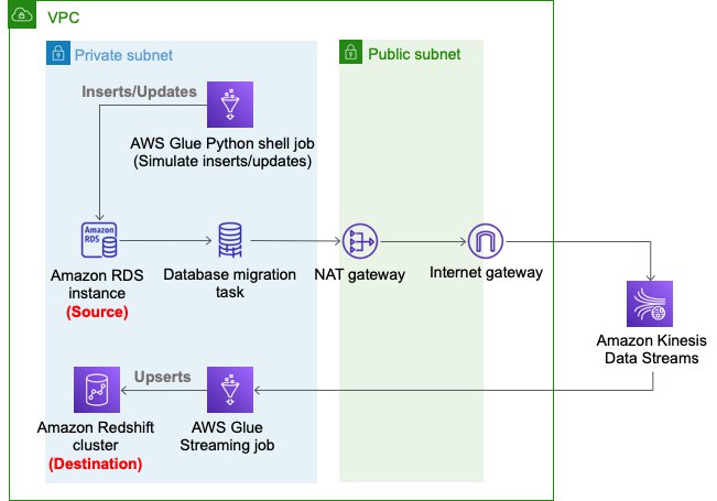
The following diagram depicts the architecture of the solution that we deploy using AWS CloudFormation.

We use an AWS DMS task to capture the changes in the source RDS instance, Kinesis Data Streams as a destination of the AWS DMS task CDC replication, and an AWS Glue streaming job to read changed records from Kinesis Data Streams and perform an upsert into the Amazon Redshift cluster. In the AWS Glue streaming job, we enrich the sports-event records.
Set up resources with AWS CloudFormation
This post includes a CloudFormation template for a quick setup. You can review and customize it to suit your needs.
The CloudFormation template generates the following resources:
- An Amazon RDS database instance (source).
- An AWS DMS replication instance, used to replicate the table
ticket_activityto Kinesis Data Streams. - A Kinesis data stream.
- An Amazon Redshift cluster (destination).
- An AWS Glue streaming job, which reads from Kinesis Data Streams and the RDS database instance, denormalizes, masks, and tokenizes the data, and upserts the records into the Amazon Redshift cluster.
- Three AWS Glue Python shell jobs:
rds-ingest-data-initial-<CloudFormation Stack name>creates four source tables on Amazon RDS and ingests the initial data into the tablessport_event,ticket, andcustomer. Sample data is automatically generated at random by Faker library.rds-ingest-data-incremental-<CloudFormation Stack name>ingests new ticket activity data into the source tableticket_activityon Amazon RDS continuously. This job simulates customer activity.rds-upsert-data-<CloudFormation Stack name>upserts specific records in the source tableticket_activityon Amazon RDS. This job simulates administrator activity.
- AWS Identity and Access Management (IAM) users and policies.
- An Amazon VPC, a public subnet, two private subnets, an internet gateway, a NAT gateway, and route tables.
- We use private subnets for the RDS database instance, AWS DMS replication instance, and Amazon Redshift cluster.
- We use the NAT gateway to have reachability to pypi.org to use MySQL Connector for Python from the AWS Glue Python shell jobs. It also provides reachability to Kinesis Data Streams and an Amazon Simple Storage Service (Amazon S3) API endpoint.
The following diagram illustrates this architecture.
To set up these resources, you must have the following prerequisites:
- IAM roles
dms-vpc-role,dms-cloudwatch-logs-role, anddms-access-for-endpoint. If you haven’t used AWS DMS before, you need to create these special IAM roles from the IAM console or the AWS Command Line Interface (AWS CLI). For instructions, see Creating the IAM roles to use with the AWS CLI and AWS DMS API. - If you already unchecked Use only IAM access control for new databases and Use only IAM access control for new tables in new databases in the AWS Lake Formation console Settings page, you need to select these two check boxes again and save your settings. For more information, see Changing the Default Security Settings for Your Data Lake.
To launch the CloudFormation stack, complete the following steps:
- Sign in to the AWS CloudFormation console.
- Choose Launch Stack:

- Choose Next.
- For S3BucketName, enter the name of your new S3 bucket.
- For VPCCIDR, enter the CIDR IP address range that doesn’t conflict with your existing networks.
- For PublicSubnetCIDR, enter the CIDR IP address range within the CIDR you gave in VPCCIDR.
- For PrivateSubnetACIDR and PrivateSubnetBCIDR, enter the CIDR IP address range within the CIDR you gave for VPCCIDR.
- For SubnetAzA and SubnetAzB, choose the subnets you want to use.
- For DatabaseUserName, enter your database user name.
- For DatabaseUserPassword, enter your database user password.
- Choose Next.
- On the next page, choose Next.
- Review the details on the final page and select I acknowledge that AWS CloudFormation might create IAM resources with custom names.
- Choose Create stack.
Stack creation can take about 20 minutes.
Ingest new records
In this section, we walk you through the steps to ingest new records.
Set up an initial source table
To set up an initial source table in Amazon RDS, complete the following steps:
- On the AWS Glue console, choose Jobs.
- Select the
job rds-ingest-data-initial-<CloudFormation stack name>. - On the Actions menu, choose Run job.
- Wait for the Run status to show as
SUCCEEDED.
This AWS Glue job creates a source table event on the RDS database instance.
Start data ingestion to the source table on Amazon RDS
To start data ingestion to the source table on Amazon RDS, complete the following steps:
- On the AWS Glue console, choose Triggers.
- Select the trigger
periodical-trigger-<CloudFormation stack name>. - On the Actions menu, choose Activate trigger.
- Choose Enable.
This trigger runs the job rds-ingest-data-incremental-<CloudFormation stack name> to ingest one record every minute.
Start data ingestion to Kinesis Data Streams
To start data ingestion from Amazon RDS to Kinesis Data Streams, complete the following steps:
- On the AWS DMS console, choose Database migration tasks.
- Select the task
rds-to-kinesis-<CloudFormation stack name>. - On the Actions menu, choose Restart/Resume.
- Wait for the Status to show as Load complete, replication ongoing.
The AWS DMS replication task ingests data from Amazon RDS to Kinesis Data Streams continuously.
Start data ingestion to Amazon Redshift
Next, to start data ingestion from Kinesis Data Streams to Amazon Redshift, complete the following steps:
- On the AWS Glue console, choose Jobs.
- Select the job
streaming-cdc-kinesis2redshift-<CloudFormation stack name>. - On the Actions menu, choose Run job.
- Choose Run job again.
This AWS Glue streaming job is implemented based on the guidelines in Updating and inserting new data. It performs the following actions:
- Creates a staging table on the Amazon Redshift cluster using the Amazon Redshift Data API
- Reads from Kinesis Data Streams, and creates a DataFrame with filtering only INSERT and UPDATE records
- Reads from three dimension tables on the RDS database instance
- Denormalizes, masks, and tokenizes the data
- Writes into a staging table on the Amazon Redshift cluster
- Merges the staging table into the destination table
- Drops the staging table
After about 2 minutes from starting the job, the data should be ingested into the Amazon Redshift cluster.
Validate the ingested data
To validate the ingested data in the Amazon Redshift cluster, complete the following steps:
- On the Amazon Redshift console, choose EDITOR in the navigation pane.
- Choose Connect to database.
- For Connection, choose Create a new connection.
- For Authentication, choose Temporary credentials.
- For Cluster, choose the Amazon Redshift cluster
cdc-sample-<CloudFormation stack name>. - For Database name, enter
dev. - For Database user, enter the user that was specified in the CloudFormation template (for example,
dbmaster). - Choose Connect.
- Enter the query
SELECT * FROM sport_event_activityand choose Run.
Now you can see the ingested records in the table sport_event_activity on the Amazon Redshift cluster. Let’s note the value of ticket_id from one of the records. For this post, we choose 1317 as an example.

Update existing records
Your Amazon Redshift cluster now has the latest data ingested from the tables on the source RDS database instance. Let’s update the data in the source table ticket_activity on the RDS database instance to see that the updated records are replicated to the Amazon Redshift cluster side.
The CloudFormation template creates another AWS Glue job. This job upserts the data with specific IDs on the source table event. To upsert the records in the source table, complete the following steps:
- On the AWS Glue console, choose Jobs.
- Choose the job
rds-upsert-data-<CloudFormation stack name>. - On the Actions menu, choose Edit job.
- Under Security configuration, script libraries, and job parameters (optional), for Job parameters, update the following parameters:
- For Key, enter
--ticket_id_to_be_updated. - For Value, replace 1 with one of the ticket IDs you observed on the Amazon Redshift console.
- For Key, enter
- Choose Save.
- Choose the job
rds-upsert-data-<CloudFormation stack name>. - On the Actions menu, choose Run job.
- Choose Run job.
This AWS Glue Python shell job simulates a customer activity to buy a ticket. It updates a record in the source table ticket_activity on the RDS database instance using the ticket ID passed in the job argument --ticket_id_to_be_updated. It automatically selects one customer, updates the field purchased_by with the customer ID, and updates the field updated_at with the current timestamp.
To validate the ingested data in the Amazon Redshift cluster, run the same query SELECT * FROM sport_event_activity. You can filter the record with the ticket_id value you noted earlier.

According to the rows returned to the query, the record ticket_id=1317 has been updated. The field updated_at has been updated from 2021-08-16 06:05:01 to 2021-08-16 06:53:52, and the field purchased_by has been updated from 449 to 14. From this result, you can see that this record has been successfully updated on the Amazon Redshift cluster side as well. You can also choose Queries in the left pane to see past query runs.
Clean up
Now to the final step, cleaning up the resources.
- Stop the AWS DMS replication task
rds-to-kinesis-<CloudFormation stack name>. - Stop the AWS Glue streaming job
streaming-cdc-kinesis2redshift-<CloudFormation stack name>. - Delete the CloudFormation stack.
Conclusion
In this post, we demonstrated how you can stream data—not only new records, but also updated records from relational databases—to Amazon Redshift. With this approach, you can easily achieve upsert use cases on Amazon Redshift clusters. In the AWS Glue streaming job, we demonstrated the common technique to denormalize, mask, and tokenize data for real-world use cases.
About the Authors
 Noritaka Sekiyama is a Principal Big Data Architect on the AWS Glue team. He enjoys collaborating with different teams to deliver results like this post. In his spare time, he enjoys playing video games with his family.
 Roman Gavrilov is an Engineering Manager at AWS Glue. He has over a decade of experience building scalable Big Data and Event-Driven solutions. His team works on Glue Streaming ETL to allow near real time data preparation and enrichment for machine learning and analytics.
Announcing Rust 1.56.0 and Rust 2021
Post Syndicated from original https://lwn.net/Articles/873655/rss
The Rust language project has announced the release of stable version 1.56.0 and the Rust 2021 edition.
We wrote about plans for the Rust 2021 Edition in May. Editions are a mechanism for opt-in changes that may otherwise pose backwards compatibility risk. See the edition guide for details on how this is achieved. This is a smaller edition, especially compared to 2018, but there are still some nice quality-of-life changes that require an edition opt-in to avoid breaking some corner cases in existing code.
See the detailed
release notes for 1.56.0 for lots more information on the release.
Swiftly Search Metadata with an Amazon S3 Serverless Architecture
Post Syndicated from Jiwan Panjiker original https://aws.amazon.com/blogs/architecture/swiftly-search-metadata-with-an-amazon-s3-serverless-architecture/
As you increase the number of objects in Amazon Simple Storage Service (Amazon S3), you’ll need the ability to search through them and quickly find the information you need.
In this blog post, we offer you a cost-effective solution that uses a serverless architecture to search through your metadata. Using a serverless architecture helps you reduce operational costs because you only pay for what you use.
Our solution is built with Amazon S3 event notifications, AWS Lambda, AWS Glue Catalog, and Amazon Athena. These services allow you to search thousands of objects in an S3 bucket by filenames, object metadata, and object keys. This solution maintains an index in an Apache Parquet file, which optimizes Athena queries to search Amazon S3 metadata. Using this approach makes it straightforward to run queries as needed without the need to ingest data or manage any servers.
Using Athena to search Amazon S3 objects
Amazon S3 stores and retrieves objects for a range of use cases, such as data lakes, websites, cloud-native applications, backups, archive, machine learning, and analytics. When you have an S3 bucket with thousands of files in it, how do you search for and find what you need? The object search box within the Amazon S3 user interface allows you to search by prefix, or you can search using Amazon S3 API’s LIST operation, which only returns 1,000 objects at a time.
A common solution to this issue is to build an external index and search for Amazon S3 objects using the external index. The Indexing Metadata in Amazon Elasticsearch Service Using AWS Lambda and Python and Building and Maintaining an Amazon S3 Metadata Index without Servers blog posts show you how to build this solution with Amazon OpenSearch Service or Amazon DynamoDB.
Our solution stores the external index in Amazon S3 and uses Athena to search the index. Athena makes it straightforward to search Amazon S3 objects without the need to manage servers or introduce another data repository. In the next section, we’ll talk about a few use cases where you can apply this solution.
Metadata search use cases
When your clients upload files to their S3 buckets, you’ll sometimes need to verify the files that were uploaded. You must validate whether you have received all the required information, including metadata such as customer identifier, category, received date, etc. The following examples will make use of this metadata:
- Searching for a file from a specific date (or) date range
- Finding all objects uploaded by a given customer identifier
- Reviewing files for a particular category
The next sections outline how to build a serverless architecture to apply to use cases like these.
Building a serverless file metadata search on AWS
Let’s go through layers that are involved in our serverless architecture solution:
- Data ingestion: Set object metadata when objects are uploaded into Amazon S3. This layer uploads objects using the Amazon S3 console, AWS SDK, REST API, and AWS CLI.
- Data processing: Integrate Amazon S3 event notifications with Lambda to process S3 events. The AWS Data Wrangler library within Lambda will transform and build the metadata index file.
- Data catalog: Use AWS Glue Data Catalog as a central repository to store table definition and add/update business-relevant attributes of the metadata index. AWS Data Wrangler API creates the Apache Parquet files to maintain the AWS Glue Catalog.
- Metadata search: Define tables for your metadata and run queries using standard SQL with Athena to get started faster.
Reference architecture
Figure 1 illustrates our approach to implementing serverless file metadata search, which consists of the following steps:
- When you create new objects/files in an S3 bucket, the source bucket is configured with Amazon S3 Event Notification events (put, post, copy, etc.). Amazon S3 events provide the metadata information required for further processing and building the metadata index file on the destination bucket.
- The S3 event is sent to a Lambda function with necessary permissions on Amazon S3 using a resource-based policy. The Lambda function processes the event with metadata and converts it into an Apache Parquet file, which is then written into a target bucket. The AWS Data Wrangler API transforms and builds the metadata index file. The Lambda layer configures AWS Data Wrangler library for necessary transformations.
- AWS Data Wrangler also creates and stores metadata in the AWS Glue Data Catalog. DataFrames are then written into target S3 buckets in Apache Parquet format. The AWS Glue Data Catalog is then updated with necessary metadata. The following example code snippet writes into an example table with columns for year, month, and date for an S3 object.
wr.s3.to_parquet(df=df, path=path, dataset=True, mode="append", partition_cols=["year","month","date"],database="example_database", table="example_table")
- With the AWS Glue Data Catalog built, Athena will use AWS Glue crawlers to automatically infer schemas and partitions of the metadata search index. Athena makes it easy to run interactive SQL queries directly into Amazon S3 by using the schema-on-read approach.

Figure 1. Serverless S3 metadata search
Athena charges based on the amount of data scanned for the query. The data being in columnar format and data partitioning will save costs as well as improve performance. Figure 2 provides a sample metadata query result from Athena.

Figure 2. Athena sample metadata query results
Conclusion
This blog post shows you how to create a robust metadata index using serverless components. This solution allows you to search files in an S3 bucket by filenames, metadata, and keys.
We showed you how to set up Amazon S3 Event Notifications, Lambda, AWS Glue Catalog, and Athena. You can use this approach to maintain an index in an Apache Parquet file, store it in Amazon S3, and use Athena queries to search S3 metadata.
Our solution requires minimal administration effort. It does not require administration and maintenance of Amazon Elastic Compute Cloud (Amazon EC2) instances, DynamoDB tables, or Amazon OpenSearch Service clusters. Amazon S3 provides scalable storage, high durability, and availability at a low cost. Plus, this solution does not require in-depth knowledge of AWS services. When not in use, it will only incur cost for Amazon S3 and possibly for AWS Glue Data Catalog storage. When needed, this solution will scale out effortlessly.
Ready to get started? Read more and get started on building Amazon S3 Serverless file metadata search:
How to Add Object Lock to Your IT Security Policy
Post Syndicated from Molly Clancy original https://www.backblaze.com/blog/how-to-add-object-lock-to-your-it-security-policy/

Object Lock is a powerful backup protection tool that makes data immutable. It allows you to store objects using a Write Once, Read Many (WORM) model, meaning after it’s written, data cannot be modified or deleted for a defined period of time. Any attempts to manipulate, copy, encrypt, change, or delete the file will fail during that time. The files may be accessed, but no one can change them, including the file owner or whoever set the Object Lock.
This makes Object Lock a great tool as part of a robust cybersecurity program. However, when Object Lock is used inconsistently, it can consume unnecessary storage resources. For example, if you set a retention period of one year, but you don’t end up needing to keep the data that long, you’re out of luck. Once the file is locked, it cannot be deleted. That’s why it’s important to develop a consistent approach.
In this post, we’ll outline five different use cases for Object Lock and explain how to add Object Lock to your IT security policies to ensure your company gets all the protection Object Lock offers while managing your storage footprint.
When to Use Object Lock: Five Use Cases
There are at least five situations where Object Lock is helpful. Keep in mind that these requirements may change over time. Compliance requirements, for example, might be relatively simple today. However, those requirements may become more complex if your company onboards customers in a highly regulated sector like finance or health care.
1. Reducing Cybersecurity Risk
Cybersecurity threats are increasing. In 2015, there were approximately 1,000 ransomware attacks per day, but this figure has increased to more than 4,000 per day since 2016, according to the U.S. government. To be clear, using Object Lock does not prevent a ransomware attack. Instead, data protected by Object Lock is immutable. In the event of a ransomware attack, it cannot be altered by malicious software. Ultimately, your organization may be able to recover from a cyber attack more quickly by restoring data protected by Object Lock.
2. Meet Compliance Requirements With Object Lock
Some industries have extensive record retention requirements. Preserving digital records with Object Lock is one way to fulfill those expectations. Several regulatory and legal requirements direct companies to retain records for a certain period of time.
- Banks insured by FDIC generally must retain account records for five years after the “account is closed or becomes dormant.” Beyond FDIC, there are many other state and federal compliance requirements on the financial industry. Preserving data with Object Lock can be helpful in these situations.
- In the health care field, requirements vary across the country. The American Health Information Management Association points out that retaining health records for up to 10 years or longer may be needed.
- You may also have to retain data for tax purposes. The IRS generally suggests keeping tax-related records for up to seven years. However, there are nuances to these requirements (i.e., shorter retention periods in some cases and potentially longer retention periods for property records).
3. Fulfilling a Legal Hold
When a company is sued, preserving all relevant records is wise. An article published by the American Bar Association points out that failing to preserve records may “undermine a litigant’s claims and defenses.” Given that many companies keep many (if not all) of their records in digital form, preserving digital records is essential. In this situation, using Object Lock to preserve records may be beneficial.
4. Meeting a Retention Period for Other Needs
Higher-risk business activities may benefit from preserving data with Object Lock. For example, an engineering company working on designing a bridge might use Object Lock to maintain records during the project. In software development, new versions of software may become unstable. Restoring to a previous version of the software, preserved from tampering or accidental deletion with Object Lock, can be valuable.
5. Replacing an LTO Tape System
In an LTO tape system, data immutability is conferred by a physical “air gap,” meaning there’s a literal gap of air between production data and backups stored on tape—the two are not physically connected in any way. Object Lock creates a virtual air gap, replacing the need for expensive physical infrastructure.

How to Add Object Lock to Your Security Policy
No matter the reason for implementing Object Lock, consistent usage is key. To encourage consistent usage, consider adding Object Lock as an option in your company’s security policy. Use the following tips as a guide on when and how to use Object Lock.
- Set Up Object Lock Governance: Assign responsibility to a single manager in IT or IT security to develop Object Lock governance policies. Then, periodically review Object Lock governance and update retention policies as necessary as the security landscape evolves.
- Evaluate the Application of Object Lock in Your Context: Are you subject to retention regulations? Do you have certain data you need to keep for an extended period of time? Take an inventory of your data and any specific retention considerations you may want to keep in mind when implementing Object Lock.
- Document Object Lock Requirements: There are different ways to explain and communicate Object Lock guidelines. If your IT security policy focuses on high-level principles, consider adding Object Lock to a data management procedure instead.
- Add Object Lock to Your Policy for Cloud Tools: Review your cloud solutions to see which providers support Object Lock. Only a few storage platforms currently offer the feature, but if your provider is one of them, you can enable Object Lock and specify the length of time an object should be locked in the storage provider’s user interface, via your backup software, or by using API calls.
- Use Change Management to Promote the Change to the Policy Internally: Writing Object Lock into your policy is a good step, but it is not the end of the process. You also need to communicate the change internally and ensure employees who need to use Object Lock are trained on the Object Lock policies and procedures.
- Testing and Monitoring: Periodically review if Object Lock is being used per the established policies and if data is being properly protected as outlined. As a starting point, review Object Lock usage quarterly and spot check data to ensure it’s locked.
Adding Object Lock to Your Security Tool Kit
Object Lock is a helpful way to protect data from being changed. It can help your organization meet records retention requirements and make it easier to recover from a cyber attack. It’s one tool that can strengthen a robust IT security practice, but you first need a well-developed backup program to keep your company operating in the event of a disruption. To find out more about emerging backup strategies, check out our explainer, “What’s the Diff: 3-2-1 vs. 4-3-2-1-0 vs. 4-3-2” to keep your valuable company data safe. And, for a comprehensive ransomware prevention playbook, check out our Complete Guide to Ransomware.
The post How to Add Object Lock to Your IT Security Policy appeared first on Backblaze Blog | Cloud Storage & Cloud Backup.
Education Summit
Post Syndicated from The Atlantic original https://www.youtube.com/watch?v=-_pnKhFq_qs
Notes from the 2021 Git Contributors’ Summit
Post Syndicated from original https://lwn.net/Articles/873629/rss
For those who are curious about where the development of Git is headed:
Johannes Schindelin has posted an
extensive set of notes from the just-concluded Git Contributors’
Summit.
We held our second all-virtual Summit over the past two days. It was the
traditional unconference style meeting, with topics being proposed and
voted on right before the introduction round. It was really good to see
the human faces behind those email addresses.32 contributors participated, and we spanned the timezones from PST to
IST.
Be sure to go into the thread for the full notes.
[$] Controlling the CPU scheduler with BPF
Post Syndicated from original https://lwn.net/Articles/873244/rss
While the BPF virtual machine has been supported by Linux for most of
the kernel’s existence, its role for much of that time was limited to, as
its full
name (Berkeley packet filter) would suggest, filtering packets. That began to change in 2012 with the introduction
of seccomp() filtering, and the pace picked up in 2014 with the arrival
of the extended BPF virtual machine. At this point, BPF hooks have found their
way into many kernel subsystems. One area that has remained BPF-free,
though, is the CPU scheduler; that could change if some version of
this patch
set from Roman Gushchin finds its way into the mainline.
Hands-On IoT Hacking: Rapid7 at DefCon IoT Village, Part 1
Post Syndicated from Deral Heiland original https://blog.rapid7.com/2021/10/21/hands-on-iot-hacking-rapid7-at-defcon-iot-village-pt-1/

This year, Rapid7 participated at the IoT Village during DefCon29 by running a hands-on hardware hacking exercise, with the goal of exposing attendees to concepts and methods for IoT hacking. Over the years, these exercises have covered several different embedded device topics, including how to use a Logic Analyzer, extracting firmware, and gaining root access to an embedded IoT device.
This year’s exercise focused on the latter and covered the following aspects:
- Interaction with Universal Asynchronous Receiver Transmitter (UART)
- Escaping the boot process to gain access to a U-Boot console
- Modification of U-Boot environment variables
- Monitoring system console during boot process for information
- Accessing failsafe (single-user mode)
- Mounting UBIFS partitions
- Modifying file system for root access
While at DefCon, we had many IoT Village attendees request a copy of our exercise manual, so I decided to create a series of in-depth write-ups about the exercise we ran there, with better explanation of several of these key topic areas. Over the course of four posts, we’ll detail the exercise and add some expanded context to answer several questions and expand on the discussion we had with attendees at this year’s DefCon IoT Village.
The device we used in our exercise was a Luma Mesh WiFi device. The only change I made to the Luma devices for the exercise was to modify the U-Boot environment variables and add console=off to the bootargs variable to disable the console. I did this to add more complexity to the exercise and show a state that is often encountered.
Identify UART
One of the first steps in gaining root access to an IoT device is to identify possible entry points, such as a UART connection. In the case of our exercise, we performed this ahead of time by locating the UART connection and soldering a 2.54 mm header onto the board. This helped streamline the exercise, so attendees could complete it in a reasonable timeframe. However, the typical method to do this is to examine the device’s circuit board looking for an empty header, as in the example shown in Figure 1:
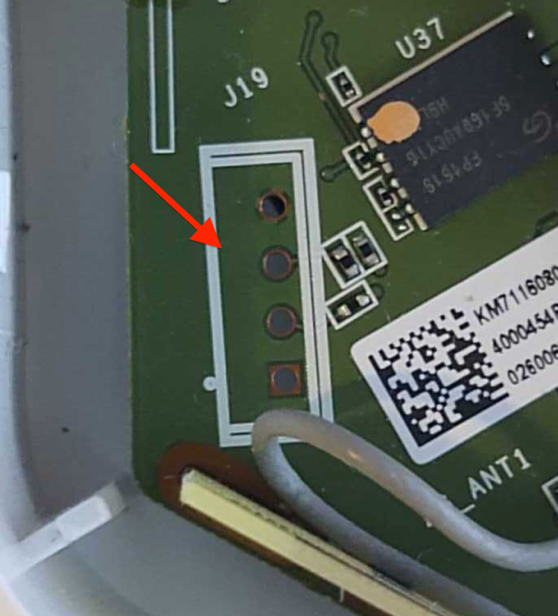
This example shows 4 port headers. Although 4 port headers are common for UART, it is not always the rule. UART connections can be included in larger port headers or may not even have an exposed header. So, when you find a header that you believe to be UART, you’ll need to validate it.
To do this, we first recommend soldering male pins into the exposed socket. This will allow easier connectivity of test equipment. An example of this is shown in Figure 2:
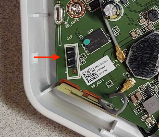
Once you’ve installed a header, I recommend using a logic analyzer to examine the connection for UART data. There are many different logic analyzers available on the market, which range in value from $12 or $15 to hundreds of dollars. In my case, I prefer using a Saleae logic analyzer.
The next step is to identify if any of the header pins are ground. To do this, first make sure the device is powered off. Then, you can use a multimeter set on continuity check and attach the ground lead “Black” to one of the metal shields covering various components on the circuit board, or one of the screws used to hold the circuit board in the cases — both often are found to be electrical ground.
Next, touch each pin in the header with the positive lead “Red” until the multimeter makes a ringing noise. This will indicate which pin is electrically ground. Once you’ve identified ground, you can attach the Logic Analyzer ground to that header pin and then connect the logic channel leads to the remaining pins, as shown in Figure 3:
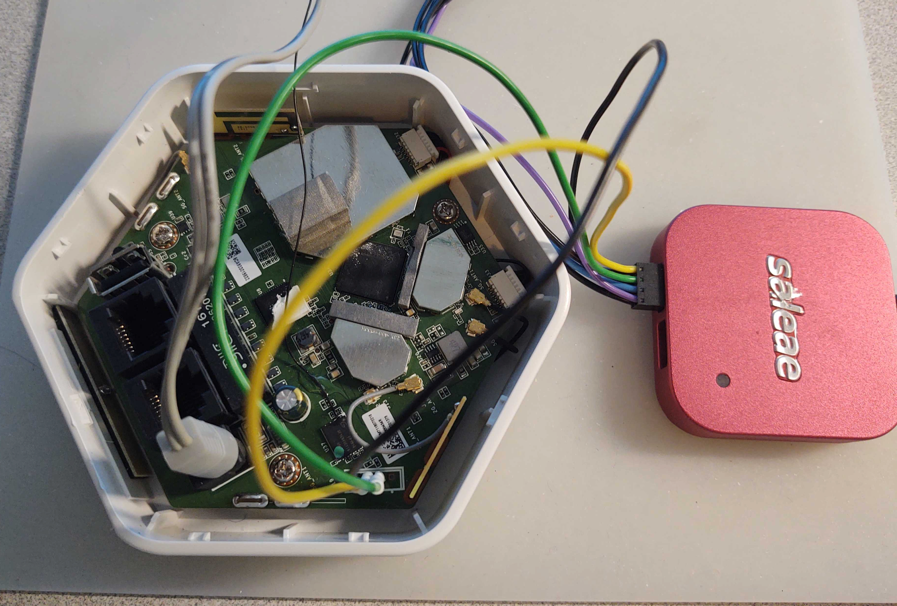
Once hooked up, make sure the appropriate analyzer software is installed and running. In my case, I used Saleae’s Logic2. You can then power on the device and capture data on this header to analyze and identify:
- Whether or not this header is UART
- What the baud rate is
- Which pin is transmit
- Which pin is receive
As shown in the capture example in Figure 4, I captured 30 seconds of data during power-up of the device for channel 0 and 1. Here, we can see that data is shown on pin 1, which in this case indicates that channel 1, if determined to be UART, is most likely connected to the transmit pin. Since we are not sending any data to the device, channel 0 should show nothing, indicating it is most likely the receive pin.
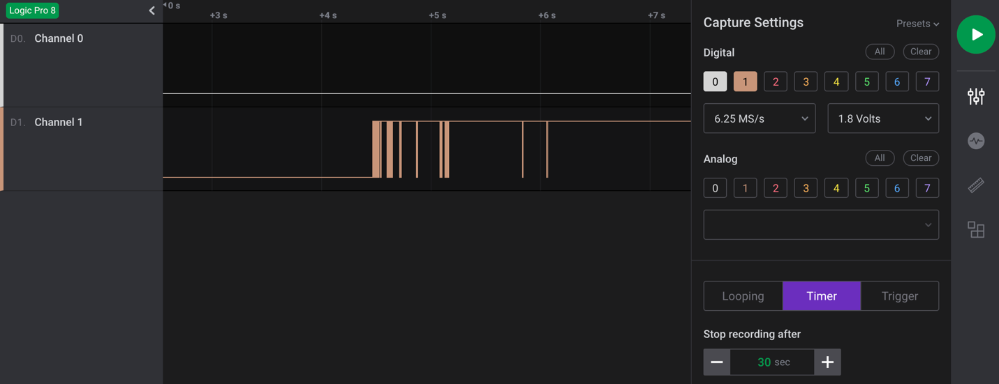
The next step is to make a final determination as to whether this is a UART header? If so, what is the baud rate?
We’ll cover this and the subsequent steps in our next post. Check back next week for more!
Security updates for Thursday
Post Syndicated from original https://lwn.net/Articles/873601/rss
Security updates have been issued by Debian (python-babel, squashfs-tools, and uwsgi), Fedora (gfbgraph and rust-coreos-installer), Mageia (aom, libslirp, redis, and vim), openSUSE (fetchmail, go1.16, go1.17, mbedtls, ncurses, python, squid, and ssh-audit), Red Hat (java-1.8.0-openjdk and java-11-openjdk), Scientific Linux (java-1.8.0-openjdk and java-11-openjdk), SUSE (fetchmail, git, go1.16, go1.17, ncurses, postgresql10, python, python36, and squid), and Ubuntu (linux, linux-aws, linux-aws-hwe, linux-azure, linux-azure-4.15, linux-dell300x, linux-gcp, linux-gcp-4.15, linux-hwe, linux-kvm, linux-raspi2, linux-snapdragon, linux, linux-bluefield, linux-gcp-5.4, linux-hwe-5.4, linux-kvm, linux-oem-5.10, and linux-oem-5.13).
Creating AWS Serverless batch processing architectures
Post Syndicated from James Beswick original https://aws.amazon.com/blogs/compute/creating-aws-serverless-batch-processing-architectures/
This post is written by Reagan Rosario, AWS Solutions Architect and Mark Curtis, Solutions Architect, WWPS.
Batch processes are foundational to many organizations and can help process large amounts of information in an efficient and automated way. Use cases include file intake processes, queue-based processing, and transactional jobs, in addition to heavy data processing jobs.
This post explains a serverless solution for batch processing to implement a file intake process. This example uses AWS Step Functions for orchestration, AWS Lambda functions for on-demand instance compute, Amazon S3 for storing the data, and Amazon SES for sending emails.
Overview
This post’s example takes a common use-case of a business’s need to process data uploaded as a file. The test file has various data fields such as item ID, order date, order location. The data must be validated, processed, and enriched with related information such as unit price. Lastly, this enriched data may need to be sent to a third-party system.
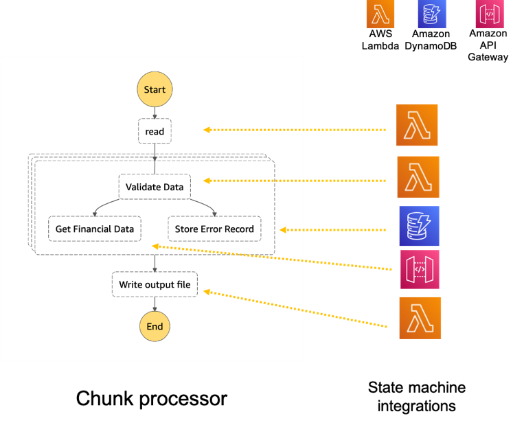
Step Functions allows you to coordinate multiple AWS services in fully managed workflows to build and update applications quickly. You can also create larger workflows out of smaller workflows by using nesting. This post’s architecture creates a smaller and modular Chunk processor workflow, which is better for processing smaller files.
As the file size increases, the size of the payload passed between states increases. Executions that pass large payloads of data between states can be stopped if they exceed the maximum payload size of 262,144 bytes.
To process large files and to make the workflow modular, I split the processing between two workflows. One workflow is responsible for splitting up a larger file into chunks. A second nested workflow is responsible for processing records in individual chunk files. This separation of high-level workflow steps from low-level workflow steps also allows for easier monitoring and debugging.
Splitting the files in multiple chunks can also improve performance by processing each chunk in parallel. You can further improve the performance by using dynamic parallelism via the map state for each chunk.
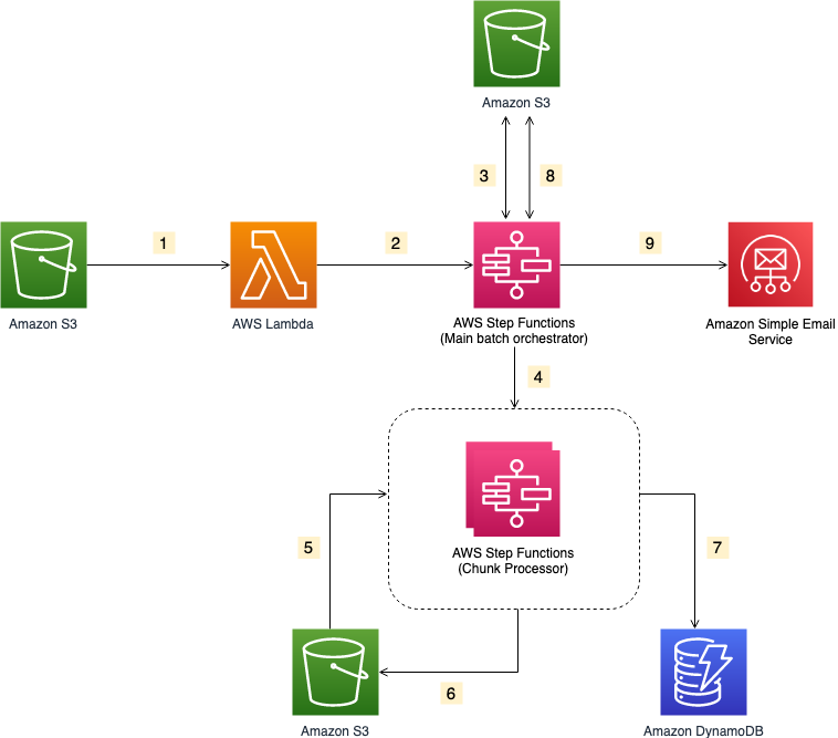
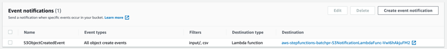
- The file upload to an S3 bucket triggers the S3 event notification. It invokes the Lambda function asynchronously with an event that contains details about the object.
- Lambda function calls the Main batch orchestrator workflow to start the processing of the file.
- Main batch orchestrator workflow reads the input file and splits it into multiple chunks and stores them in an S3 bucket.
- Main batch orchestrator then invokes the Chunk Processor workflow for each split file chunk.
- Each Chunk processor workflow execution reads and processes a single split chunk file.
- Chunk processor workflow writes the processed chunk file back to the S3 bucket.
- Chunk processor workflow writes the details about any validation errors in an Amazon DynamoDB table.
- Main batch orchestrator workflow then merges all the processed chunk files and saves it to an S3 bucket.
- Main batch orchestrator workflow then emails the consolidated files to the intended recipients using Amazon Simple Email Service.
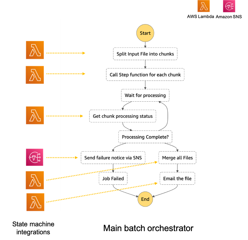
- The Main batch orchestrator workflow orchestrates the processing of the file.
- The first task state Split Input File into chunks calls a Lambda function. It splits the main file into multiple chunks based on the number of records and stores each chunk into an S3 bucket.
- The next task state Call Step Functions for each chunk invokes a Lambda function. It triggers a workflow for each chunk of the file. It passes information such as the name of bucket and the key where the chunk file to be processed is present.
- Then we wait for all the child workflow executions to complete.
- Once all the child workflows are processed successfully, the next task state is Merge all Files. This combines all the processed chunks into a single file and then stores the file back to the S3 bucket.
- The next task state Email the file takes the output file. It generates an S3 presigned URL for the file and sends an email with the S3 presigned URL.

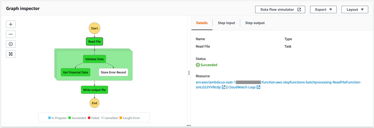
- The Chunk processor workflow is responsible for processing each row from the chunk file that was passed.
- The first task state Read reads the chunked file from S3 and converts it to an array of JSON objects. Each JSON object represents a row in the chunk file.
- The next state is a map state called Process messages (not shown in the preceding visual workflow). It runs a set of steps for each element of an input array. The input to the map state is an array of JSON objects passed by the previous task.
- Within the map state, Validate Data is the first state. It invokes a Lambda function that validates each JSON object using the rules that you have created. Records that fail validation are stored in an Amazon DynamoDB table.
- The next state Get Financial Data invokes Amazon API Gateway endpoints to enrich the data in the file with data from a DynamoDB table.
- When the map state iterations are complete, the Write output file state triggers a task. It calls a Lambda function, which converts the JSON data back to CSV and writes the output object to S3.
Prerequisites
- AWS account.
- AWS SAM CLI.
- Python 3.
- An AWS Identity and Access Management (IAM) role with appropriate access.
Deploying the application
- Clone the repository.
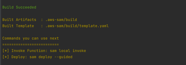
- Change to the directory and build the application source:
sam build

- Package and deploy the application to AWS. When prompted, input the corresponding parameters as shown below:
sam deploy –guided
 Note the template parameters:
 -
- SESSender: The sender email address for the output file email.
- SESRecipient: The recipient email address for the output file email.
- SESIdentityName: An email address or domain that Amazon SES users use to send email.
- InputArchiveFolder: Amazon S3 folder where the input file will be archived after processing.
- FileChunkSize: Size of each of the chunks, which is split from the input file.
- FileDelimiter: Delimiter of the CSV file (for example, a comma).
- After the stack creation is complete, you see the source bucket created in Outputs.

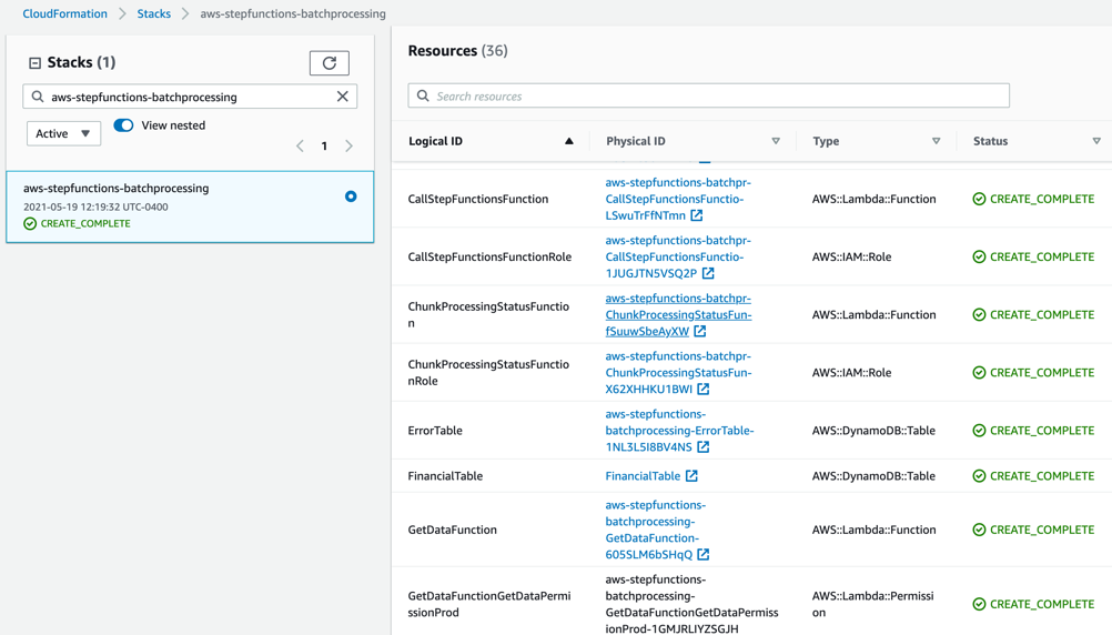
- Review the deployed components in the AWS CloudFormation Console.

 Note the template parameters:
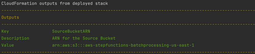
Testing the solution
- Before you can send an email using Amazon SES, you must verify each identity that you’re going to use as a “From”, “Source”, “Sender”, or “Return-Path” address to prove that you own it. Refer Verifying identities in Amazon SES for more information.
- Locate the S3 bucket (SourceBucket) in the Resources section of the CloudFormation stack. Choose the physical ID.

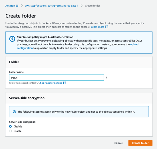
- In the S3 console for the SourceBucket, choose Create folder. Name the folder input and choose Create folder.

- The S3 event notification on the SourceBucket uses “input” as the prefix and “csv” as the suffix. This triggers the notification Lambda function. This is created as a part of the custom resource in the AWS SAM template.

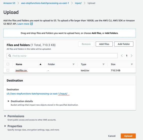
- In the S3 console for the SourceBucket, choose the Upload button. Choose Add files and browse to the input file (testfile.csv). Choose Upload.

- Review the data in the input file testfile.csv.

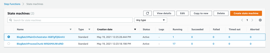
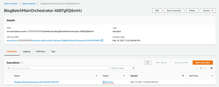
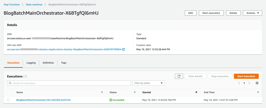
- After the object is uploaded, the event notification triggers the Lambda Function. This starts the main orchestrator workflow. In the Step Functions console, you see the workflow is in a running state.

- Choose an individual state machine to see additional information.

- After a few minutes, both BlogBatchMainOrchestrator and BlogBatchProcessChunk workflows have completed all executions. There is one execution for the BlogBatchMainOrchestrator workflow and multiple invocations of the BlogBatchProcessChunk workflow. This is because the BlogBatchMainOrchestrator invokes the BlogBatchProcessChunk for each of the chunked files.


Checking the output
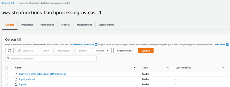
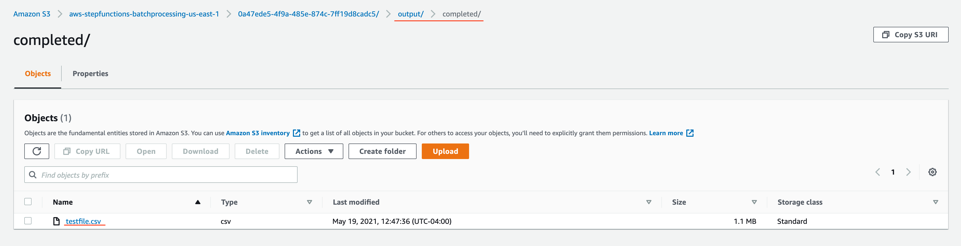
- Open the S3 console and verify the folders created after the process has completed.

The following subfolders are created after the processing is complete:
– input_archive – Folder for archival of the input object.
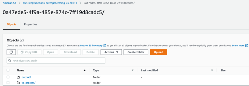
– 0a47ede5-4f9a-485e-874c-7ff19d8cadc5 – Subfolder with a unique UUID in the name. This is created for storing the objects generated during batch execution. - Select the folder 0a47ede5-4f9a-485e-874c-7ff19d8cadc5.

output – This folder contains the completed output objects, some housekeeping files, and processed chunk objects.
 to_process – This folder contains all the split objects from the original input file.

- Open the processed object from the output/completed folder.

Inspect the output object testfile.csv. It is enriched with additional data (columns I through N) from the DynamoDB table fetched through an API call.
 to_process – This folder contains all the split objects from the original input file.
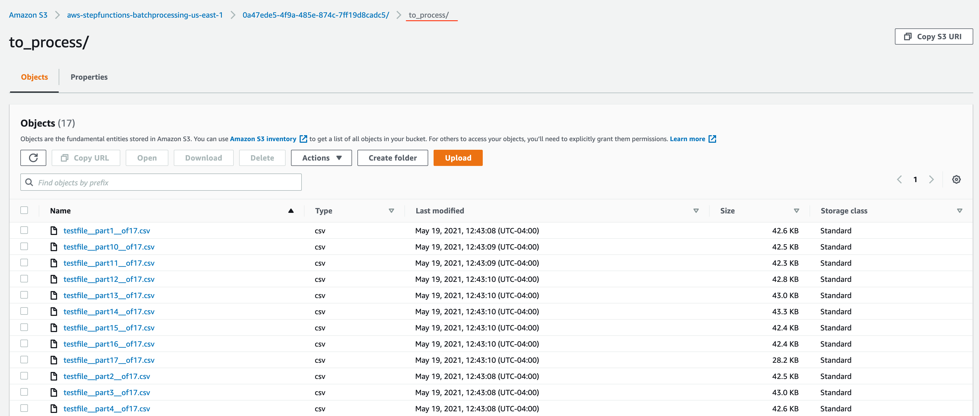

Viewing a completed workflow
Open the Step Functions console and browse to the BlogBatchMainOrchestrator and BlogBatchProcessChunk state machines. Choose one of the executions of each to locate the Graph Inspector. This shows the execution results for each state.
BlogBatchMainOrchestrator:

BlogBatchProcessChunk:
Batch performance
For this use case, this is the time taken for the batch to complete, based on the number of input records:
| No. of records | Time for batch completion |
| 10 k | 5 minutes |
| 100 k | 7 minutes |
The performance of the batch depends on other factors such as the Lambda memory settings and data in the file. Read more about Profiling functions with AWS Lambda Power Tuning.
Conclusion
This blog post shows how to use Step Functions’ features and integrations to orchestrate a batch processing solution. You use two Steps Functions workflows to implement batch processing, with one workflow splitting the original file and a second workflow processing each chunk file.
The overall performance of our batch processing application is improved by splitting the input file into multiple chunks. Each chunk is processed by a separate state machine. Map states further improve the performance and efficiency of workflows by processing individual rows in parallel.
Download the code from this repository to start building a serverless batch processing system.
Additional Resources:
- Orchestration examples with Step Functions
- Create a Serverless Workflow
- Building Business Workflows with AWS Step Functions
- Using a Map State to Call Lambda Multiple Times
For more serverless learning resources, visit Serverless Land.
Без държава за бъдеще и капачките са бъдеще
Post Syndicated from original https://bivol.bg/%D0%B1%D0%B5%D0%B7-%D0%B4%D1%8A%D1%80%D0%B6%D0%B0%D0%B2%D0%B0-%D0%B7%D0%B0-%D0%B1%D1%8A%D0%B4%D0%B5%D1%89%D0%B5-%D0%B8-%D0%BA%D0%B0%D0%BF%D0%B0%D1%87%D0%BA%D0%B8%D1%82%D0%B5-%D1%81%D0%B0-%D0%B1%D1%8A.html
четвъртък 21 октомври 2021

Сега, на пръв поглед нещата са кристално ясни. Всички знаем, че българското здравеопазване е бездънна каца, в която се набутват едни милиарди, а те изчезват яко дим, без какъвто и…
Problems with Multifactor Authentication
Post Syndicated from Bruce Schneier original https://www.schneier.com/blog/archives/2021/10/problems-with-multifactor-authentication.html
Roger Grimes on why multifactor authentication isn’t a panacea:
The first time I heard of this issue was from a Midwest CEO. His organization had been hit by ransomware to the tune of $10M. Operationally, they were still recovering nearly a year later. And, embarrassingly, it was his most trusted VP who let the attackers in. It turns out that the VP had approved over 10 different push-based messages for logins that he was not involved in. When the VP was asked why he approved logins for logins he was not actually doing, his response was, “They (IT) told me that I needed to click on Approve when the message appeared!”
And there you have it in a nutshell. The VP did not understand the importance (“the WHY”) of why it was so important to ONLY approve logins that they were participating in. Perhaps they were told this. But there is a good chance that IT, when implementinthe new push-based MFA, instructed them as to what they needed to do to successfully log in, but failed to mention what they needed to do when they were not logging in if the same message arrived. Most likely, IT assumed that anyone would naturally understand that it also meant not approving unexpected, unexplained logins. Did the end user get trained as to what to do when an unexpected login arrived? Were they told to click on “Deny” and to contact IT Help Desk to report the active intrusion?
Or was the person told the correct instructions for both approving and denying and it just did not take? We all have busy lives. We all have too much to do. Perhaps the importance of the last part of the instructions just did not sink in. We can think we hear and not really hear. We can hear and still not care.
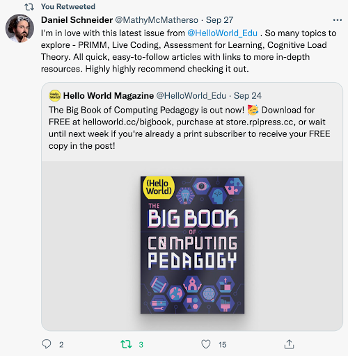
Hello World’s first-ever special edition is here!
Post Syndicated from Gemma Coleman original https://www.raspberrypi.org/blog/hello-world-big-book-of-computing-pedagogy/
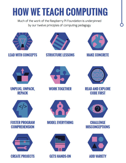
Hello World, our free magazine for computing and digital making educators, has just published its very first special edition: The Big Book of Computing Pedagogy!
“When I started to peruse the draft for The Big Book of Computing Pedagogy, I was simply stunned.”
Monica McGill, founder & CEO of CSEDResearch.org

This special edition focuses on practical approaches to teaching computing in the classroom, and includes some of our favourite pedagogically themed articles from previous issues of Hello World, as well as a few never-seen-before pieces. It is structured around twelve pedagogical principles, first developed by us as part of our work related to the National Centre for Computing Education in England. These twelve principles are based on up-to-date research around the best ways of approaching the teaching and learning of computing.

Grounded in research and practice
Computing education is still relatively new, and it’s a field that’s constantly changing and adapting. Despite leaving school less than ten years ago, I remember my days in the computer lab being limited to learning about how to add animations on PowerPoints and trying out basic Excel formulas (and yes, there was still the odd mouse with a ball knocking about!).
Computing education research is even younger, and we are proud to be an important part of this growing space. As an organisation, we engage in rigorous original research around computing education and learning for young people, and we share all of our research work through blogs, reports, research seminars, and academic publications. We’re particularly proud to have partnered with the University of Cambridge to establish the Raspberry Pi Computing Education Research Centre.
The Big Book of Computing Pedagogy represents another way in which we bring research and practice to computing educators in an accessible and engaging way. The book aims to be an educator’s companion to learning about tried and tested approaches to teaching computing.
It includes articles on techniques for fostering program comprehension, advice for bringing physical computing to your classroom, and introductions to frameworks for structuring your computing lessons. As with all Hello World content, we’re bridging the gap between research and practice by giving you accessible chunks of research, followed by stories of trusty educators who have tried out the approaches in their classroom or educational space.
Monica McGill, founder and CEO of CSEDResearch.org, says about Hello World’s latest offering, “When I started to peruse the draft for The Big Book of Computing Pedagogy, I was simply stunned. I found the ready-to-consume content to be solidly based on research evidence and tried-and-true best practices from teachers themselves. This resource provides valuable insights into introducing computing to students via unplugged activities, integrating the Predict–Run–Investigate–Modify–Make (PRIMM) pedagogical model, and introducing physical devices for computing — all written in a way that teachers can adopt and use in their own classrooms.”
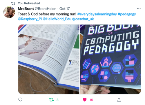
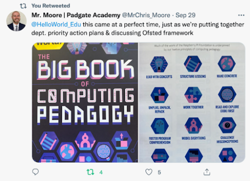
We’ve been thrilled to see the reaction of educators to this special edition, with many teachers already using it as a reference guide and for a spot of CPD. Why not join them and download it for free today?
Subscribe now to get each new Hello World — whether regular issue or special edition — straight to your digital inbox, for free! And if you’re based in the UK and do paid or unpaid work in education, you can subscribe for free print issues.
PS Have you listened to our Hello World podcast yet? A new episode has just come out, and it’s great! Listen and subscribe wherever you get your podcasts.
The post Hello World’s first-ever special edition is here! appeared first on Raspberry Pi.
Designing products and services based on Jobs to be Done
Post Syndicated from Grab Tech original https://engineering.grab.com/designing-products-and-services-based-on-jtbd
Introduction
In 2016, Clayton Christensen, a Harvard Business School professor, wrote a book called Competing Against Luck. In his book, he talked about the kind of jobs that exist in our everyday life and how we can uncover hidden jobs through the act of non-consumption. Non-consumption is the inability for a consumer to fulfil an important Job to be Done (JTBD).
JTBD is a framework; it is a different way of looking at consumer goals and is based on the notion that people buy products and services to get a job done. In this article, we will walk through what the JTBD framework is, look at an example of a popular JTBD, and look at how we use the JTBD framework in one of Grab’s services.
JTBD framework
In his book, Clayton Christensen gives the example of the milkshake, as a JTBD example. In the mid-90s, a fast food chain was trying to understand how to improve the milkshakes they were selling and how they could sell more milkshakes. To sell more, they needed to improve the product. To understand the job of the milkshake, they interviewed their customers. They asked their customers why they were buying the milkshakes, and what progress the milkshake would help them make.
Job 1: To fill their stomachs
One of the key insights was the first job, the customers wanted something that could fill their stomachs during their early morning commute to the office. Usually, these car drives would take one to two hours, so they needed something to keep them awake and to keep themselves full.
In this scenario, the competition could be a banana, but think about the properties of a banana. A banana could fill your stomach but your hands get dirty and sticky after peeling it. Bananas cannot do a good job here. Another competitor could be a Snickers bar, but it is rather unhealthy, and depending on how many bites you take, you could finish it in one minute.
By understanding the job the milkshake was performing, the restaurant now had a specific way of improving the product. The milkshake could be made milkier so it takes time to drink through a straw. The customer can then enjoy the milkshake throughout the journey; the milkshake is optimised for the job.
Job 2: To make children happy
As part of the study, they also interviewed parents who came to buy milkshakes in the afternoon, around 3:00 PM. They found out that the parents were buying the milkshakes to make their children happy.
By knowing this, they were able to optimise the job by offering a smaller version of the milkshake which came in different flavours like strawberry and chocolate. From this milkshake example, we learn that multiple jobs can exist for one product. From that, we can make changes to a product to meet those different jobs.
JTBD at GrabFood
A team at GrabFood wanted to prioritise which features or products to build, and performed a prioritisation exercise. However, there was a lack of fundamental understanding of why our consumers were using GrabFood or any other food delivery services. To gain deeper insights on this, we conducted a JTBD study.
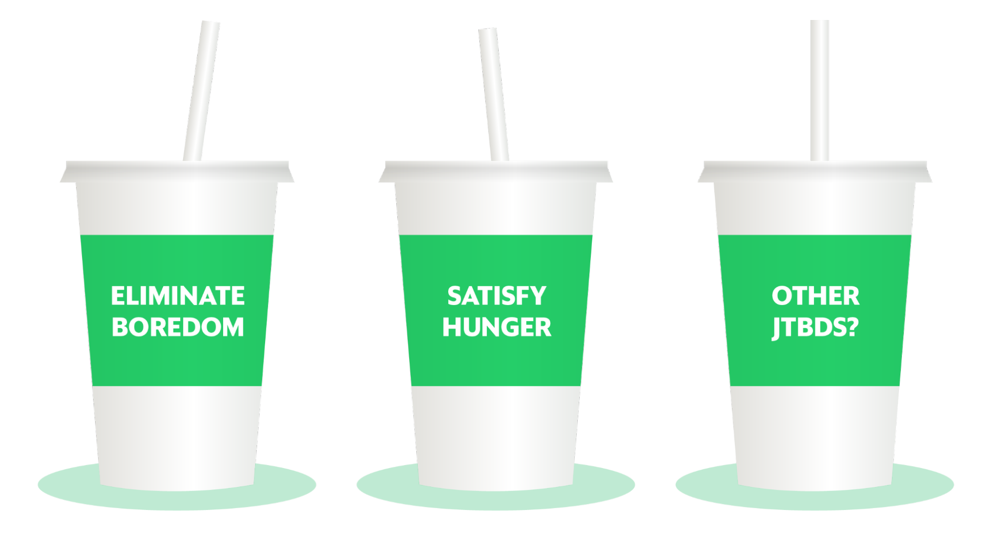
We applied the JTBD framework in our research investigation. We used the force diagram framework to find out what job a consumer wanted to achieve and the corresponding push and pull factors driving the consumer’s decision. A job here is defined as the progress that the consumer is trying to make in a particular context.
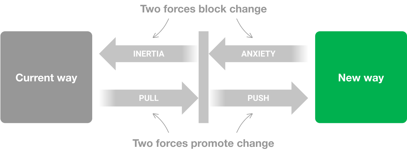
There were four key points in the force diagram:
- What jobs are people using GrabFood for?
- What did people use prior to GrabFood to get the jobs done?
- What pushed them to seek a new solution? What is attractive about this new solution?
- What are the things that will make them go back to the old product? What are the anxieties of the new product?
By applying this framework, we progressively asked these questions in our interview sessions:
- Can you remind us of the last time you used GrabFood? — This was to uncover the situation or the circumstances.
- Why did you order this food? — This was to get down to the core of the need.
- Can you tell us, before GrabFood, what did you use to get the same job done?
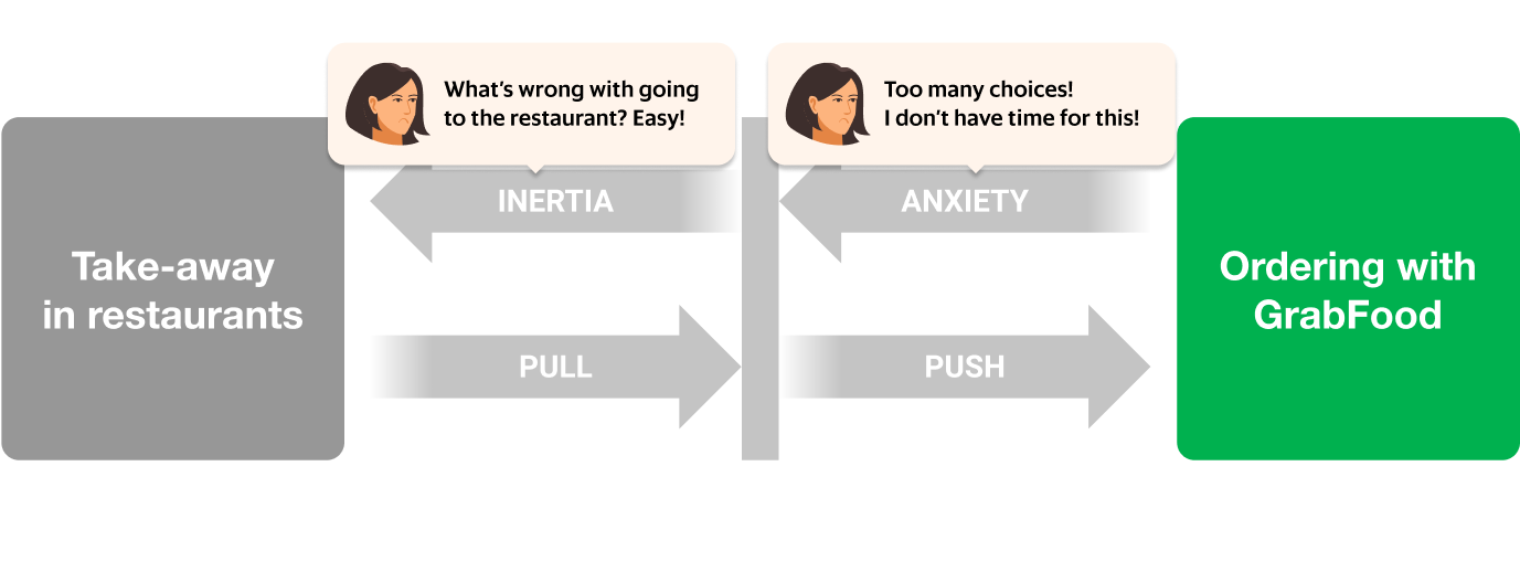
From the interview sessions, we were able to uncover a number of JTBDs, one example was working parents buying food for their families. Before GrabFood, most of them were buying from food vendors directly, but that is a time consuming activity and it adds additional friction to an already busy day. This led them in search of a new solution and GrabFood provided that solution.
Let’s look at this JTBD in more depth. One anxiety that parents had when ordering GrabFood was the sheer number of choices they had to make in order to check out their order:
There was already a solution for this problem: bundles! Food bundles is a well-known concept from the food and beverage industry; items that complement each other are bundled together for a more efficient checkout experience.
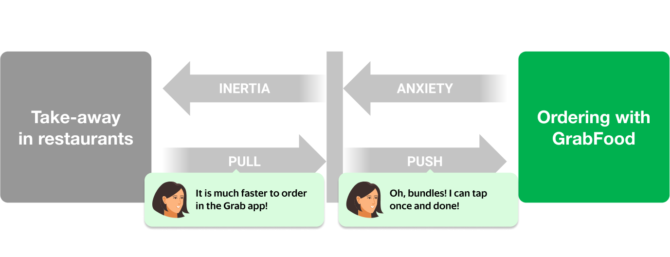
However, not all GrabFood merchants created bundles to solve this problem for their consumers. This was an untapped opportunity for the merchants to solve a critical problem for their consumers. Eureka! We knew that we needed to help merchants create bundles in an efficient way to solve for the consumer’s JTBD.
We decided to add a functionality to the GrabMerchant app that allowed merchants to create bundles. We built an algorithm that matched complementary items and automatically suggested these bundles to merchants. The merchant only had to tap a button to create a bundle instantly.
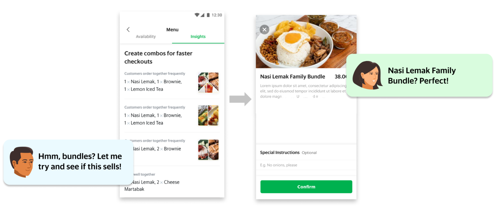
The feature was released and thousands of restaurants started adding bundles to their menu. Our JTBD analysis proved to be correct: food and beverage entrepreneurs were now equipped with an essential tool to drive growth and we removed an obstacle for parents to choose GrabFood to solve for their JTBD.
Conclusion
At Grab, we understand the importance of research. We educate designers and other non-researcher employees to conduct research studies. We also encourage the sharing of research findings, and we ensure that research insights are consumable. By using the JTBD framework and asking questions specifically to understand the job of our consumers and partners, we are able to gain fundamental understanding of why our consumers are using our products and services. This helps us improve our products and services, and optimise it for the jobs that need to be done throughout Southeast Asia.
This article was written based on an episode of the Grab Design Podcast – a conversation with Grab Lead Researcher Soon Hau Chua. Want to listen to the Grab Design Podcast? Join the team, we’re hiring!
Special thanks to Amira Khazali and Irene from Tech Learning.
Join us
Grab is a leading superapp in Southeast Asia, providing everyday services that matter to consumers. More than just a ride-hailing and food delivery app, Grab offers a wide range of on-demand services in the region, including mobility, food, package and grocery delivery services, mobile payments, and financial services across over 400 cities in eight countries.
Powered by technology and driven by heart, our mission is to drive Southeast Asia forward by creating economic empowerment for everyone. If this mission speaks to you, join our team today!
[$] LWN.net Weekly Edition for October 21, 2021
Post Syndicated from original https://lwn.net/Articles/872946/rss
The LWN.net Weekly Edition for October 21, 2021 is available.