Zabbix API scripting via curl and jq

Post Syndicated from Aigars Kadiķis original https://blog.zabbix.com/zabbix-api-scripting-via-curl-and-jq/12434/

In this lab we will use a bash environment and utilities ‘curl’ and ‘jq’ to perform Zabbix API calls, do some scripting.

‘curl’ is a tool to exchange JSON messages over HTTP/HTTPS.
‘jq’ utility helps to locate and extract specific elements in output.

To follow the lab we need to install ‘jq’:

# On CentOS7/RHEL7:
yum install epel-release && yum install jq

# On CentOS8/RHEL8:
dnf install jq

# On Ubuntu/Debian:
apt install jq

# On any 64-bit Linux platform:
curl -skL "https://github.com/stedolan/jq/releases/download/jq1.5/jq-linux64" -o /usr/bin/jq && chmod +x /usr/bin/jq

Obtaining an authorization token

In order to operate with API calls we need to:

  • Define an API endpoint. this is an URL, a PHP file which is designed to accept requests
  • Obtain an authorization token

If you tend to execute API calls from frontend server then most likelly.

url=http://127.0.0.1/api_jsonrpc.php
# or:
url=http://127.0.0.1/zabbix/api_jsonrpc.php

It’s required to set the URL variable to jump to the next step. Test if you have it configured:

echo $url

Any API call needs to be used via authorization token. To put one token in variable use the command:

auth=$(curl -s -X POST -H 'Content-Type: application/json-rpc' \
-d '
{"jsonrpc":"2.0","method":"user.login","params":
{"user":"api","password":"zabbix"},
"id":1,"auth":null}
' $url | \
jq -r .result
)

Note
Notice there is user ‘api’ with password ‘zabbix’. This is a dedicated user for API calls.

Check if you have a session key. It should be 32 character HEX string:

echo $auth

Though process

1) visit the documentation page and pick an API flavor for example alert.get:

{
"jsonrpc": "2.0",
"method": "alert.get",
"params": {
	"output": "extend",
	"actionids": "3"
},
"auth": "038e1d7b1735c6a5436ee9eae095879e",
"id": 1
}

2) Let’s use our favorite text editor and build in Find&Replace functionality to escape all double quotes:

{
\"jsonrpc\": \"2.0\",
\"method\": \"alert.get\",
\"params\": {
	\"output\": \"extend\",
	\"actionids\": \"3\"
},
\"auth\": \"038e1d7b1735c6a5436ee9eae095879e\",
\"id\": 1
}

NOTE
Don’t ever think to do this process manually by hand!

3) Replace session key 038e1d7b1735c6a5436ee9eae095879e with our variable $auth

{
\"jsonrpc\": \"2.0\",
\"method\": \"alert.get\",
\"params\": {
	\"output\": \"extend\",
	\"actionids\": \"3\"
},
\"auth\": \"$auth\",
\"id\": 1
}

4) Now let’s encapsulate the API command with curl:

curl -s -X POST \
-H 'Content-Type: application/json-rpc' \
-d " \

{
\"jsonrpc\": \"2.0\",
\"method\": \"alert.get\",
\"params\": {
	\"output\": \"extend\",
	\"actionids\": \"3\"
},
\"auth\": \"$auth\",
\"id\": 1
}

" $url

By executing the previous command, it should already print a JSON content in response.
To make the output more beautiful we can pipe it to jq .:

curl -s -X POST \
-H 'Content-Type: application/json-rpc' \
-d " \

{
\"jsonrpc\": \"2.0\",
\"method\": \"alert.get\",
\"params\": {
	\"output\": \"extend\",
	\"actionids\": \"3\"
},
\"auth\": \"$auth\",
\"id\": 1
}

" $url | jq .

Wrap everything together in one file

This is ready to use the snippet:

#!/bin/bash

# 1. set connection details
url=http://127.0.0.1/api_jsonrpc.php
user=api
password=zabbix

# 2. get authorization token
auth=$(curl -s -X POST \
-H 'Content-Type: application/json-rpc' \
-d " \
{
 \"jsonrpc\": \"2.0\",
 \"method\": \"user.login\",
 \"params\": {
  \"user\": \"$user\",
  \"password\": \"$password\"
 },
 \"id\": 1,
 \"auth\": null
}
" $url | \
jq -r '.result'
)

# 3. show triggers in problem state
curl -s -X POST \
-H 'Content-Type: application/json-rpc' \
-d " \
{
 \"jsonrpc\": \"2.0\",
    \"method\": \"trigger.get\",
    \"params\": {
        \"output\": \"extend\",
        \"selectHosts\": \"extend\",
        \"filter\": {
            \"value\": 1
        },
        \"sortfield\": \"priority\",
        \"sortorder\": \"DESC\"
    },
    \"auth\": \"$auth\",
    \"id\": 1
}
" $url | \
jq -r '.result'

# 4. logout user
curl -s -X POST \
-H 'Content-Type: application/json-rpc' \
-d " \
{
    \"jsonrpc\": \"2.0\",
    \"method\": \"user.logout\",
    \"params\": [],
    \"id\": 1,
    \"auth\": \"$auth\"
}
" $url

Conveniences

We can use https://jsonpathfinder.com/ to identify what should be the path to extract an element.

For example, to list all Zabbix proxies we will use and API call:

curl -s -X POST \
-H 'Content-Type: application/json-rpc' \
-d " \
{
    \"jsonrpc\": \"2.0\",
    \"method\": \"proxy.get\",
    \"params\": {
        \"output\": [\"host\"]
    },
    \"auth\": \"$auth\",
    \"id\": 1
} 
" $url

It may print content like:

{"jsonrpc":"2.0","result":[{"host":"broceni","proxyid":"10387"},{"host":"mysql8mon","proxyid":"12066"},{"host":"riga","proxyid":"12585"}],"id":1}

Inside JSONPathFinder by using a mouse click at the right panel, we can locate a sample element what we need to extract:

It suggests a path ‘x.result[1].host’. This means to extract all elements we can remove the number and use ‘.result[].host’ like this:

curl -s -X POST \
-H 'Content-Type: application/json-rpc' \
-d " \
{
    \"jsonrpc\": \"2.0\",
    \"method\": \"proxy.get\",
    \"params\": {
        \"output\": [\"host\"]
    },
    \"auth\": \"$auth\",
    \"id\": 1
} 
" $url | jq -r '.result[].host'

Now it prints only the proxy titles:

broceni
mysql8mon
riga

That is it for today. Bye.

Network-layer DDoS attack trends for Q3 2020

Post Syndicated from Omer Yoachimik original https://blog.cloudflare.com/network-layer-ddos-attack-trends-for-q3-2020/

Network-layer DDoS attack trends for Q3 2020

Network-layer DDoS attack trends for Q3 2020

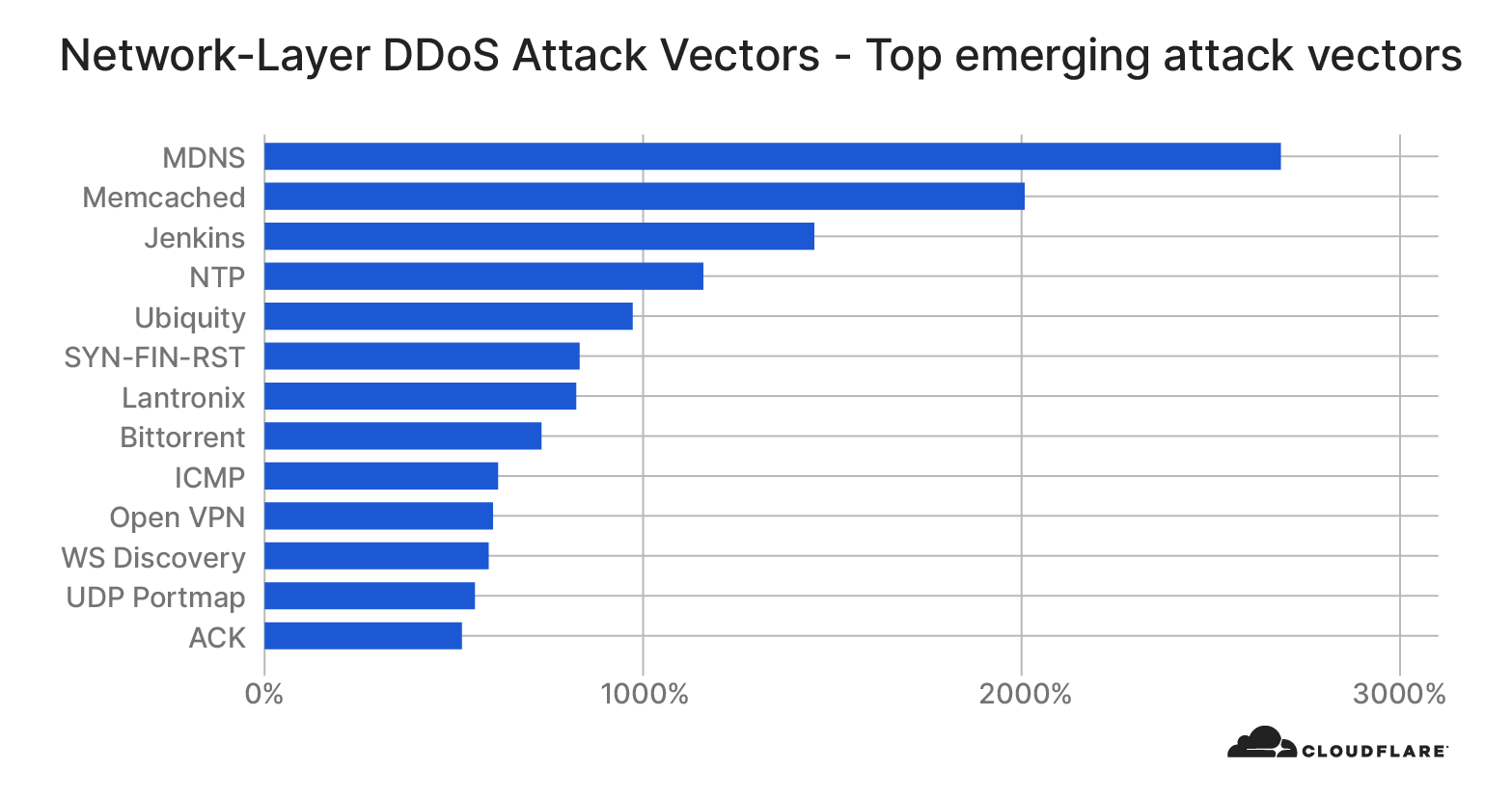
DDoS attacks are surging — both in frequency and sophistication. After doubling from Q1 to Q2, the total number of network layer attacks observed in Q3 doubled again — resulting in a 4x increase in number compared to the pre-COVID levels in the first quarter. Cloudflare also observed more attack vectors deployed than ever — in fact, while SYN, RST, and UDP floods continue to dominate the landscape, we saw an explosion in protocol specific attacks such as mDNS, Memcached, and Jenkins DoS attacks.

Here are other key network layer DDoS trends we observed in Q3:

  • Majority of the attacks are under 500 Mbps and 1 Mpps — both still suffice to cause service disruptions
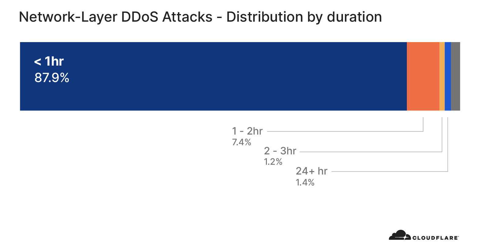
  • We continue to see a majority of attacks be under 1 hr in duration
  • Ransom-driven DDoS attacks (RDDoS) are on the rise as groups claiming to be Fancy Bear, Cozy Bear and the Lazarus Group extort organizations around the world. As of this writing, the ransom campaign is still ongoing. See a special note on this below.

Number of attacks

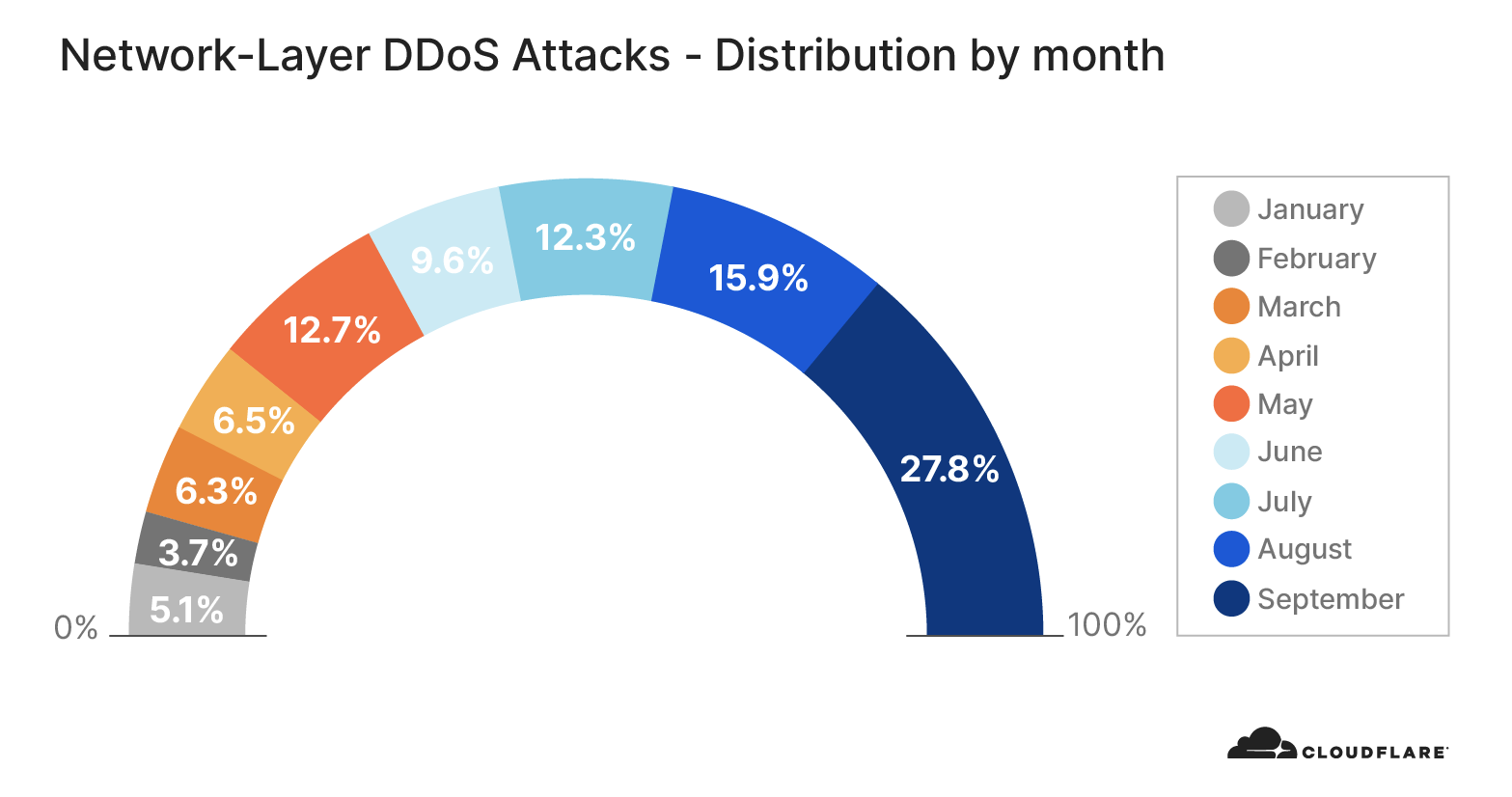
The total number of L3/4 DDoS attacks we observe on our network continues to increase substantially, as indicated in the graph below. All in all, Q3 saw over 56% of all attacks this year — double that of Q2, and four times that of Q1. In addition, the number of attacks per month increased throughout the quarter.

Network-layer DDoS attack trends for Q3 2020

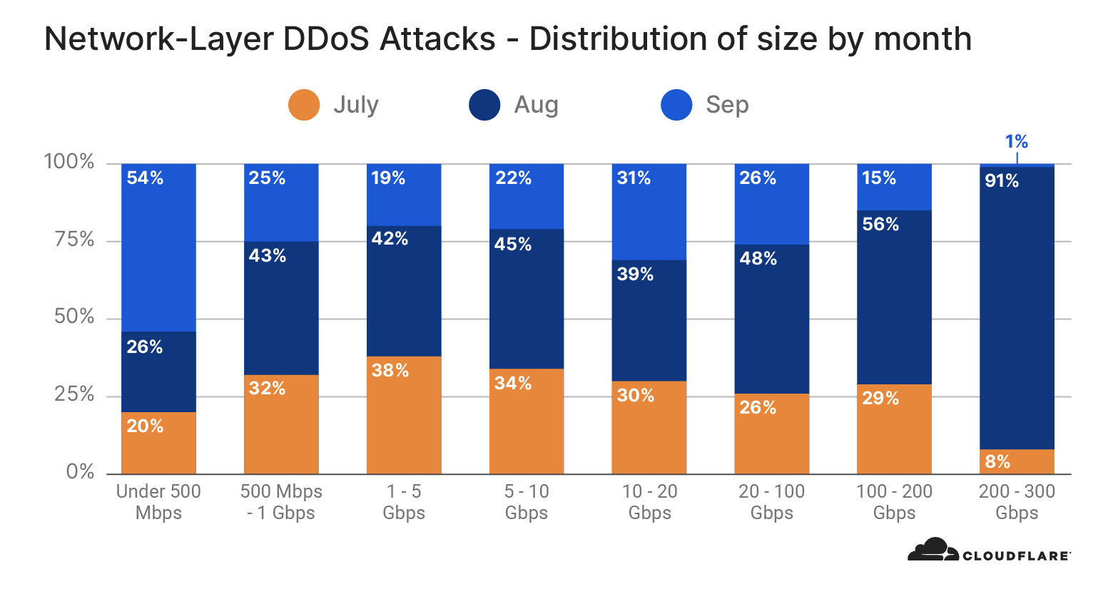
While September witnessed the largest number of attacks overall, August saw the most large attacks (over 500Mbps). Ninety-one percent of large attacks in Q3 took place in that month—while monthly distribution of other attack sizes was far more even.

Network-layer DDoS attack trends for Q3 2020

While the total number of attacks between 200-300 Gbps decreased in September, we saw more global attacks on our network in Q3. This suggests the increase in the use of distributed botnets to launch attacks. In fact, in early July, Cloudflare witnessed one of the largest-ever attacks on our network — generated by Moobot, a Mirai-based botnet. The attack peaked at 654 Mbps and originated from 18,705 unique IP addresses, each believed to be a Moobot-infected IoT device. The attack campaign lasted nearly 10 days, but the customer was protected by Cloudflare, so they observed no downtime or service degradation.

Attack size (bit rate and packet rate)

There are different ways of measuring a L3/4 DDoS attack’s size. One is the volume of traffic it delivers, measured as the bit rate (specifically, Gigabits-per-second). Another is the number of packets it delivers, measured as the packet rate (specifically, packets-per-second). Attacks with high bit rates attempt to saturate the Internet link, and attacks with high packet rates attempt to overwhelm the routers or other in-line hardware devices.

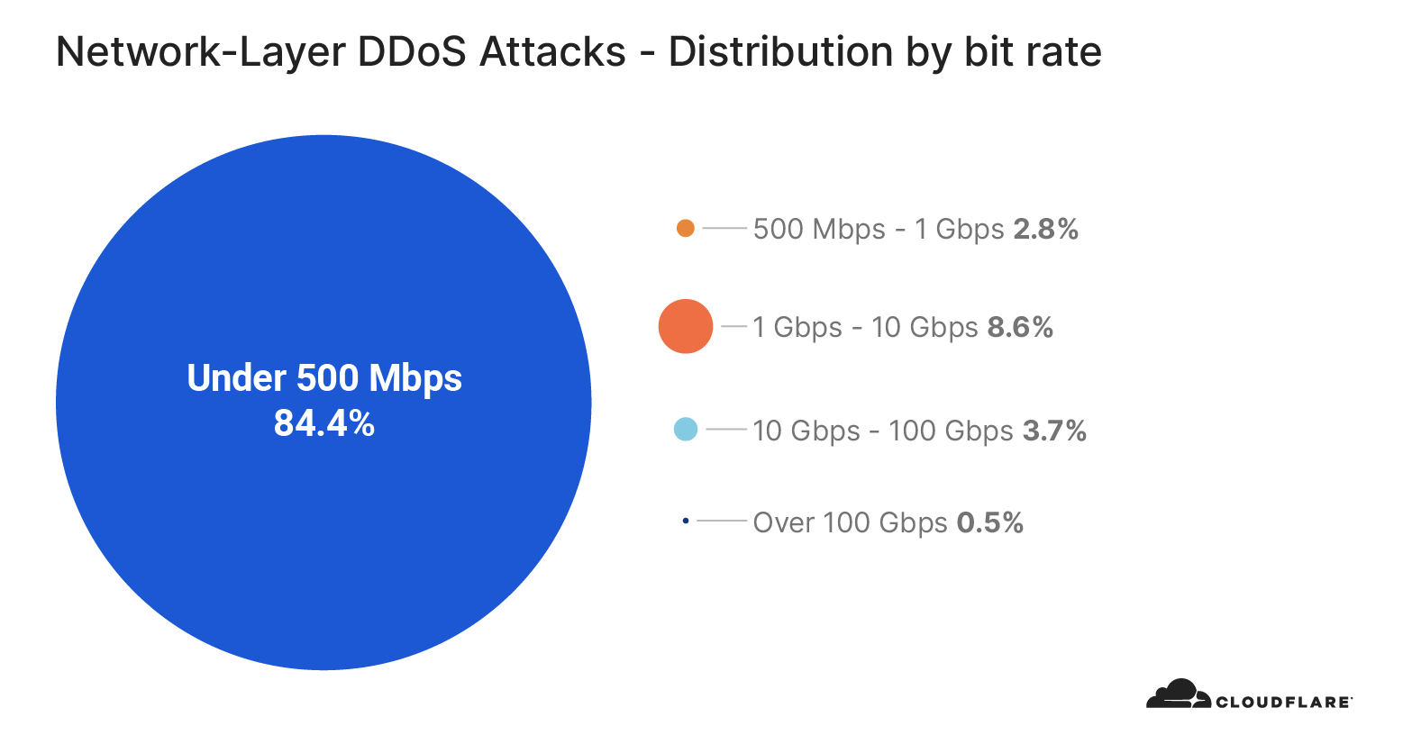
In Q3, most of the attacks we observed were smaller in size. In fact, over 87% of all attacks were under 1 Gbps. This represents a significant increase from Q2, when roughly 52% of attacks were that small.  Note that, even ‘small’ attacks of under 500 Mbps are many times sufficient to create major disruptions for Internet properties that are not protected by a Cloud based DDoS protection service. Many organizations have uplinks provided by their ISPs that are far less than 1 Gbps. Assuming their public facing network interface also serves legitimate traffic, you can see how even these ‘small’ DDoS attacks can easily take down Internet properties.

Network-layer DDoS attack trends for Q3 2020

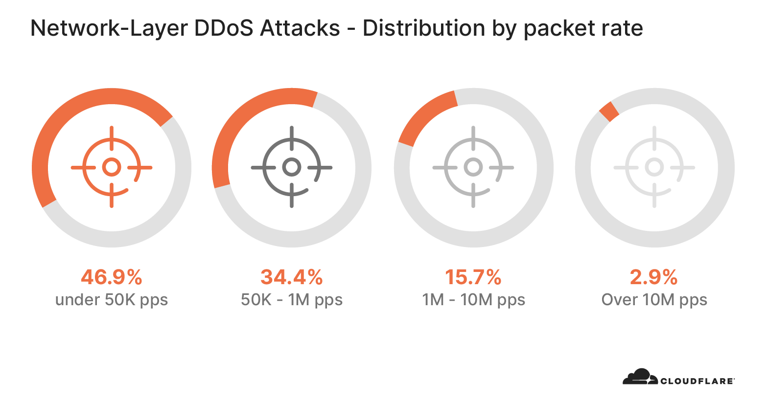
This trend holds true for attack packet rates. In Q3, 47% of attacks were under 50k pps — compared to just 19% in Q2.

Network-layer DDoS attack trends for Q3 2020

Smaller attacks can indicate that amateur attackers may be behind the attacks — using tools easily available to generate attacks on exposed IPs/ networks. Alternatively, small attacks may serve as a smokescreen to distract security teams from other kinds of cyberattacks that might be taking place simultaneously.

Attack duration

Network-layer DDoS attack trends for Q3 2020

In terms of length, very short attacks were the most common attack type observed in Q3, accounting for nearly 88% of all attacks. This observation is in line with our prior reports — in general, Layer 3/4 DDoS attacks are getting shorter in duration.

Short burst attacks may attempt to cause damage without being detected by DDoS detection systems. DDoS services that rely on manual analysis and mitigation may prove to be useless against these types of attacks because they are over before the analyst even identifies the attack traffic.

Alternatively, the use of short attacks may be used to probe the cyber defenses of the target. Load-testing tools and automated DDoS tools, that are widely available on the dark web, can generate short bursts of, say, a SYN flood, and then following up with another short attack using an alternate attack vector. This allows attackers to understand the security posture of their targets before they decide to potentially launch larger attacks at larger rates and longer durations – which come at a cost.

In other cases, attackers generate small DDoS attacks as proof and warning to the target organization of the attacker’s ability to cause real damage later on. It’s often followed by a ransom note to the target organization, demanding payment so as to avoid suffering an attack that could more thoroughly cripple network infrastructure.

Whatever their motivation, DDoS attacks of any size or duration are not going away anytime soon. Even short DDoS attacks cause harm, and having an automated real-time defense mechanism in place is critical for any online business.

Attack vectors

SYN floods constituted nearly 65% of all attacks observed in Q3, followed by RST floods and UDP floods in second and third places. This is relatively consistent with observations from previous quarters, highlighting the DDoS attack vector of choice by attackers.

While TCP based attacks like SYN and RST floods continue to be popular, UDP-protocol specific attacks such as mDNS, Memcached, and Jenkins are seeing an explosion compared to the prior quarter.

Network-layer DDoS attack trends for Q3 2020

Multicast DNS (mDNS) is a UDP-based protocol that is used in local networks for service/device discovery. Vulnerable mDNS servers respond to unicast queries originating outside of the local network, which are ‘spoofed’ (altered) with the victim’s source address. This results in amplification attacks. In Q3, we noticed an explosion of mDNS attacks — specifically, we saw a 2,680% increase compared to the previous quarter.

This was followed by Memcached and Jenkins attacks. Memcached is a Key Value database. Requests can be made over the UDP protocol with a spoofed source address of the target. The size of the Value stored in the requested Key will affect the amplification factor, resulting in a DDoS amplification attack. Similarly, Jenkins, NTP, Ubiquity and the other UDP based protocols have seen a dramatic increase over the quarter due to its UDP stateless nature. A vulnerability in the older version (Jenkins 2.218 and earlier) aided the launch of DDoS attacks. This vulnerability was fixed in Jenkins 2.219 by disabling UDP multicast/ broadcast messages by default. However there are still many vulnerable and exposed devices that run UDP based services which are being harnessed to generate volumetric amplification attacks.

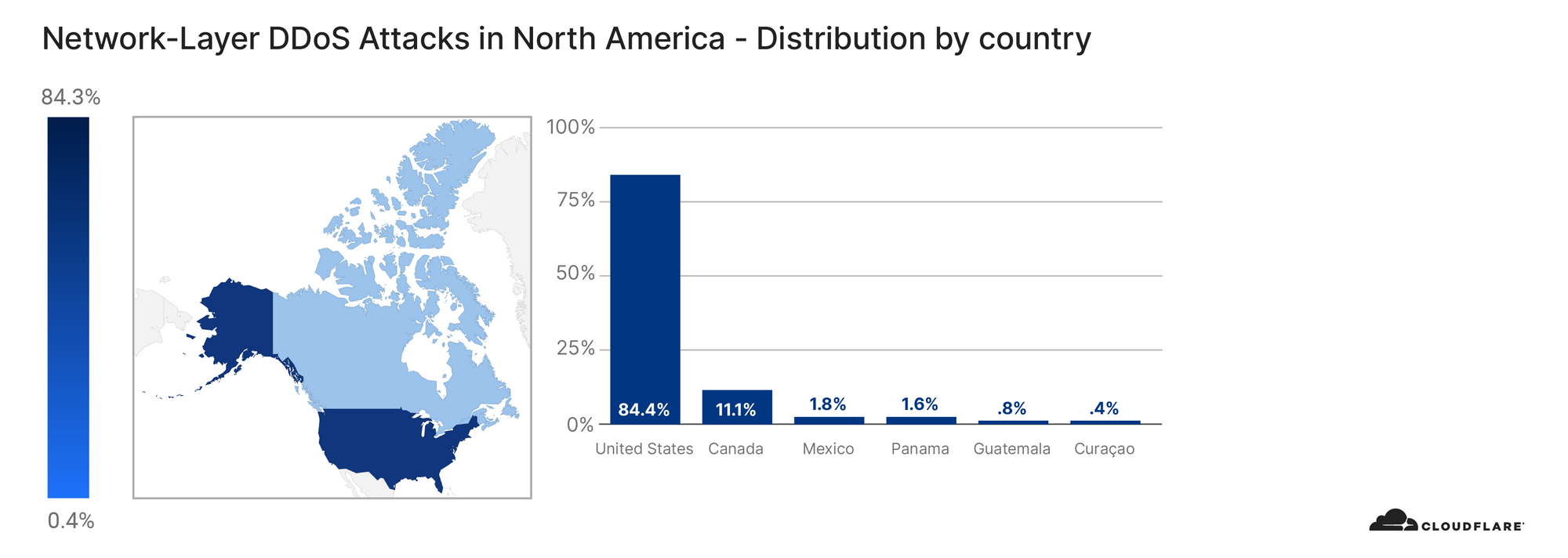
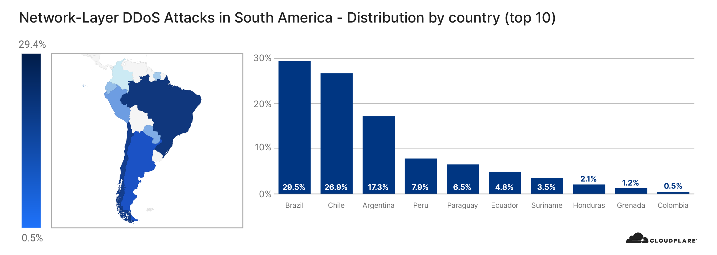
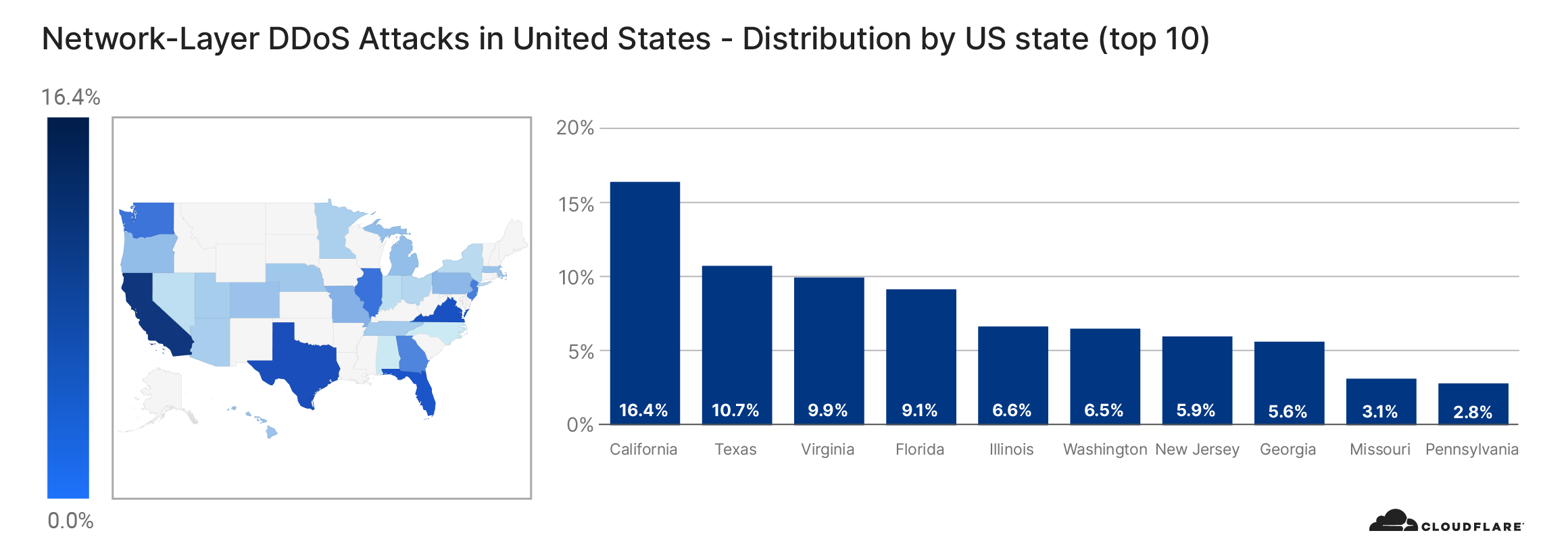
Attack by country

Network-layer DDoS attack trends for Q3 2020

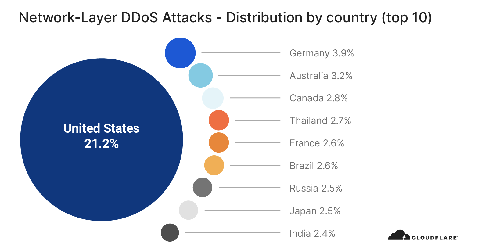
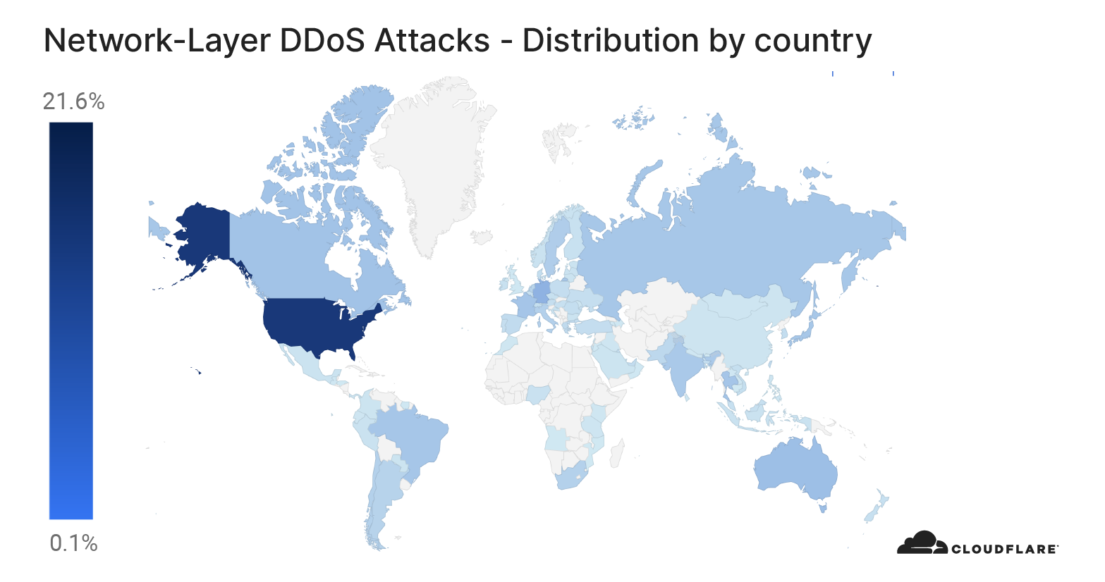
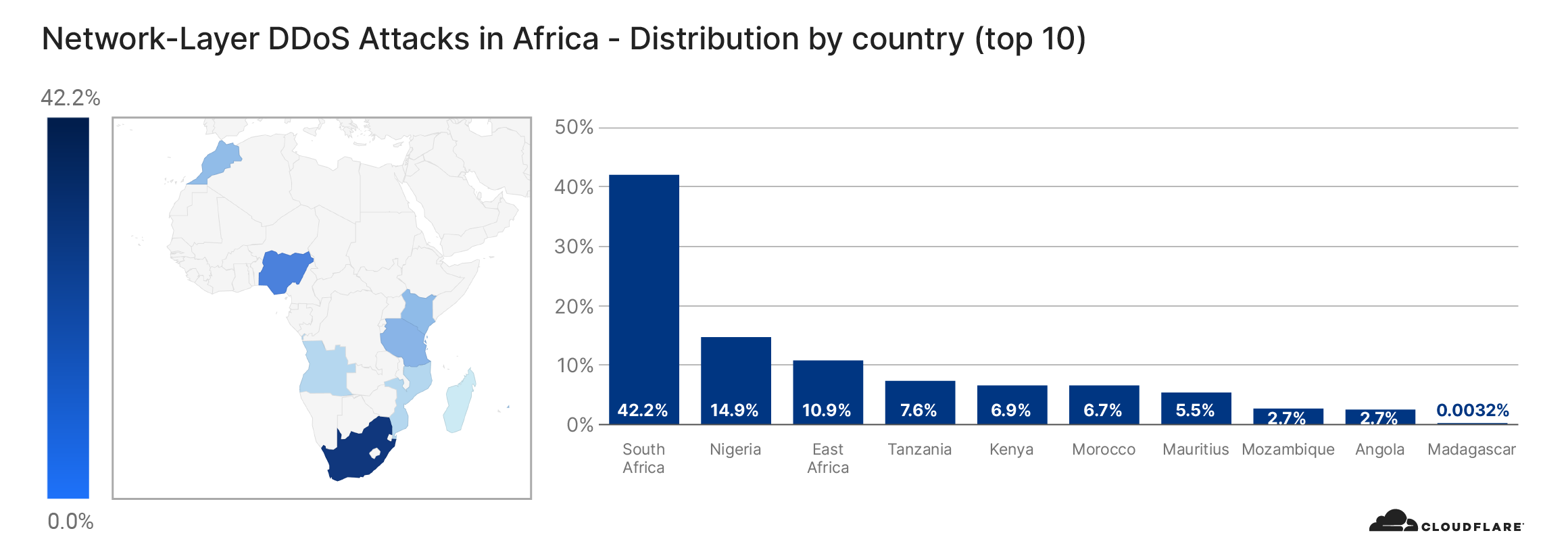
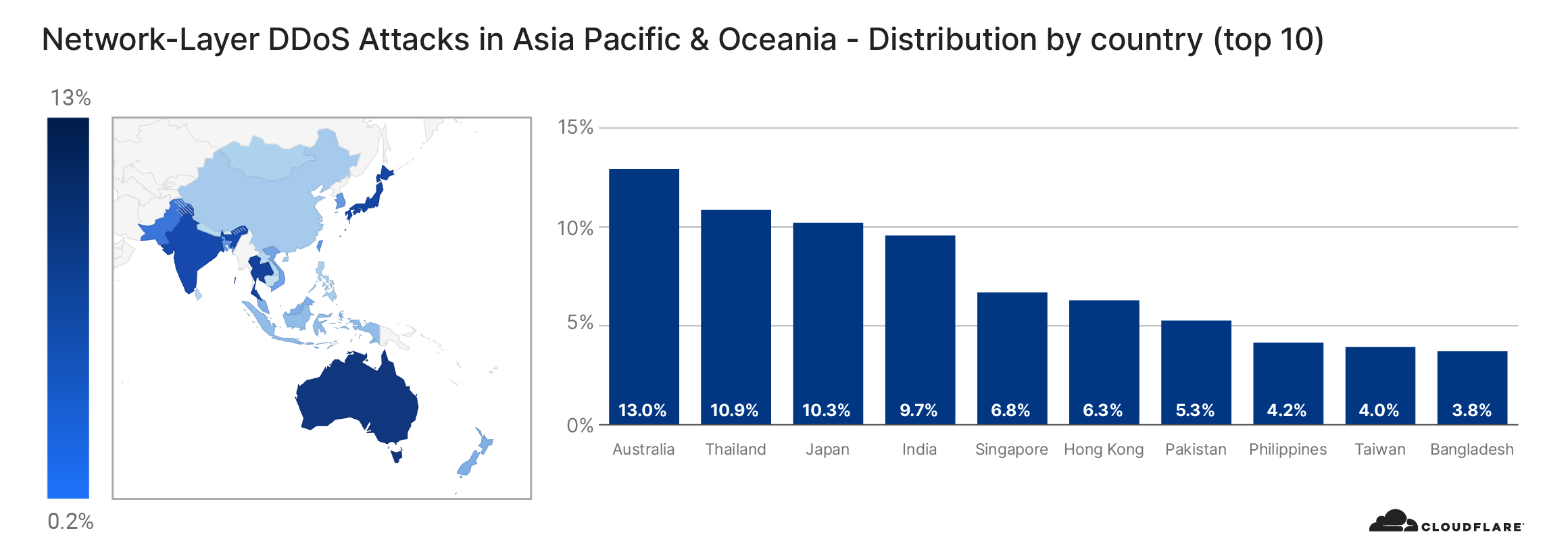
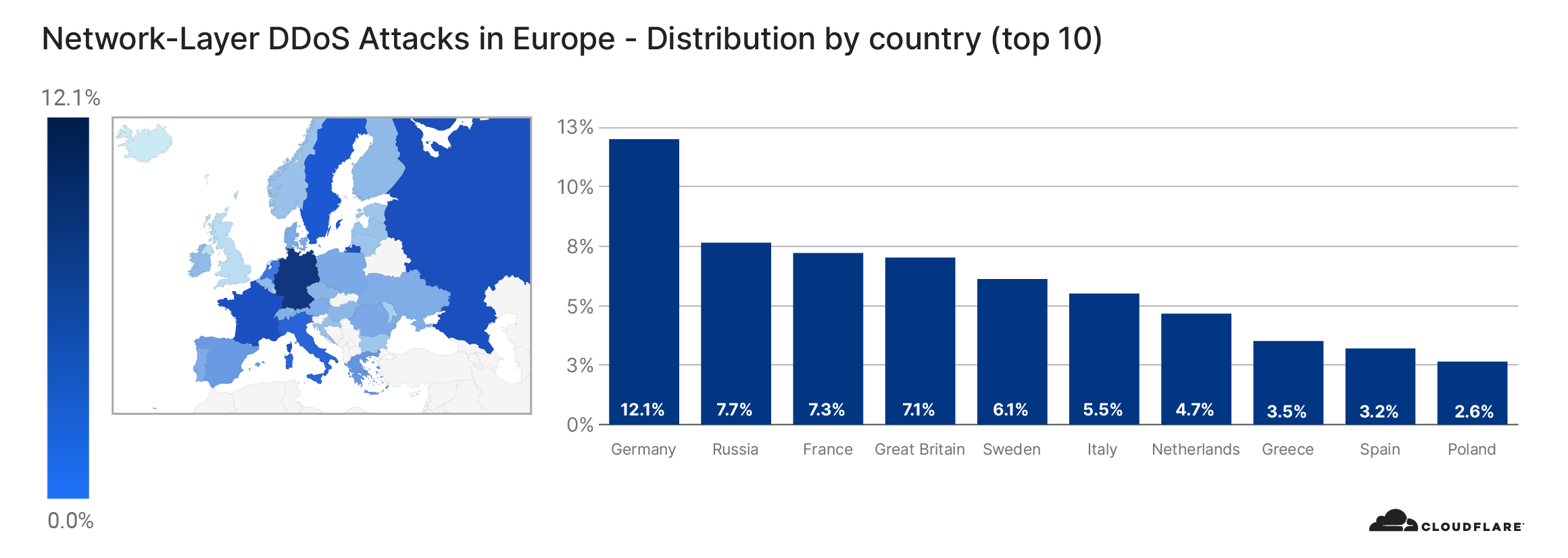
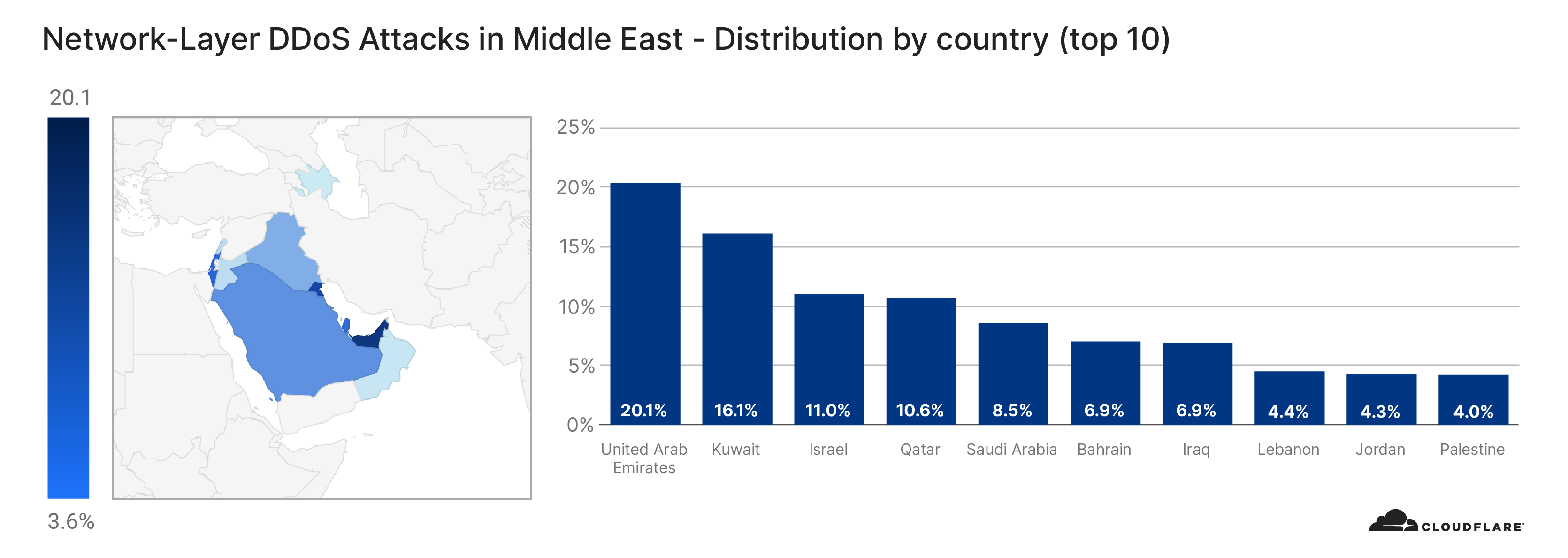
Looking at country-based distribution, the United States observed the most number of L3/4 DDoS attacks, followed by Germany and Australia. Note that when analyzing L3/4 DDoS attacks, we bucket the traffic by the Cloudflare edge data center locations where the traffic was ingested, and not by the location of the source IP. The reason is when attackers launch L3/4 attacks they can spoof the source IP address in order to obfuscate the attack source. If we were to derive the country based on a spoofed source IP, we would get a spoofed country. Cloudflare is able to overcome the challenges of spoofed IPs by displaying the attack data by the location of Cloudflare’s data center in which the attack was observed. We’re able to achieve geographical accuracy in our report because we have data centers in over 200 cities around the world.

Africa

Network-layer DDoS attack trends for Q3 2020

Asia Pacific & Oceania

Network-layer DDoS attack trends for Q3 2020

Europe

Network-layer DDoS attack trends for Q3 2020

Middle East

Network-layer DDoS attack trends for Q3 2020

North America

Network-layer DDoS attack trends for Q3 2020

South America

Network-layer DDoS attack trends for Q3 2020

United States

Network-layer DDoS attack trends for Q3 2020

A note on recent ransom-driven DDoS attacks

Over the past months, Cloudflare has observed another disturbing trend — a rise in extortion and ransom-based DDoS (RDDoS) attacks targeting organizations around the world. While RDDoS threats do not always result in an actual attack, the cases seen in recent months show that attacker groups are willing to carry out the threat, launching large scale DDoS attacks that can overwhelm organizations that lack adequate protection. In some cases, the initial teaser attack may be sufficient to cause impact if not protected by a Cloud based DDoS protection service.

In a RDDoS attack, a malicious party threatens a person or organization with a cyberattack that could knock their networks, websites, or applications offline for a period of time, unless the person or organization pays a ransom. You can read more about RDDoS attacks here.

Entities claiming to be Fancy Bear, Cozy Bear, and Lazarus have been threatening to launch DDoS attacks against organizations’ websites and network infrastructure unless a ransom is paid before a given deadline. Additionally, an initial ‘teaser’ DDoS attack is usually launched as a form of demonstration before parallel to the ransom email. The demonstration attack is typically a UDP reflection attack using a variety of protocols, lasting roughly 30 minutes in duration (or less).

What to do if you receive a threat:

  1. Do not panic and we recommend you to not pay the ransom: Paying the ransom only encourages bad actors, finances illegal activities —and there’s no guarantee that they won’t attack your network now or later.
  2. Notify local law enforcement: They will also likely request a copy of the ransom letter that you received.
  3. Contact Cloudflare: We can help ensure your website and network infrastructure are safeguarded from these ransom attacks.

Cloudflare DDoS protection is different

On-prem hardware/cloud-scrubbing centers can’t address the challenges of modern volumetric DDoS attacks. Appliances are easily overwhelmed by large DDoS attacks, Internet links quickly saturate, and rerouting traffic to cloud scrubbing centers introduces unacceptable latency penalties. Our cloud-native, always-on, automated DDoS protection approach solves problems that traditional cloud signaling approaches were originally created to address.

Cloudflare’s mission is to help build a better Internet, which grounds our DDoS approach and is why in 2017, we pioneered unmetered DDoS mitigation for all of our customers on all plans including the free plan. We are able to provide this level of protection because every server on our network can detect & block threats, enabling us to absorb attacks of any size/kind, with no latency impact. This architecture gives us unparalleled advantages compared to any other vendor.

  • 51 Tbps of DDoS mitigation capacity and under 3 sec TTM: Every data center in Cloudflare’s network detects and mitigates DDoS attacks. Once an attack is identified, the Cloudflare’s local data center mitigation system (dosd) generates and applies a dynamically crafted rule with a real-time signature — and mitigates attacks in under 3 seconds globally on average. This 3-second Time To Mitigate (TTM) is one of the fastest in the industry. Firewall rules and “proactive”/static configurations take effect immediately.
  • Fast performance included:  Cloudflare is architected so that customers do not incur a latency penalty as a result of attacks. We deliver DDoS protection from every Cloudflare data center (instead of legacy scrubbing centers or on-premise hardware boxes) which allows us to mitigate attacks closest to the source. Cloudflare analyzes traffic out-of-path ensuring that our DDoS mitigation solution doesn’t add any latency to legitimate traffic. The rule is applied at the most optimal place in the Linux stack for a cost efficient mitigation, ensuring no performance penalty.
  • Global Threat Intelligence: Like an immune system, our network learns from/mitigates attacks against any customer to protect them all. With threat intelligence (TI), it automatically blocks attacks and is employed in customer facing features (Bot Fight mode, Firewall Rules & Security Level). Users create custom rules to mitigate attacks based on traffic attribute filters, threat & bot scores generated using ML models (protecting against bots/botnets/DDoS).

To learn more about Cloudflare’s DDoS solution contact us or get started.

Defeat evil with a Raspberry Pi foam-firing spy camera

Post Syndicated from Ashley Whittaker original https://www.raspberrypi.org/blog/defeat-evil-with-a-raspberry-pi-foam-firing-spy-camera/

Ruth and Shawn from YouTube channel Kids Invent Stuff picked a cool idea by 9-year-old Nathan, who drew a Foam-Firing Spy Camera, to recreate in real life.

FYI: that’s not really a big camera lens…

The trick with spy devices is to make sure they look as much like the object they’re hidden inside as possible. Where Raspberry Pi comes in is making sure the foam camera can be used as a real photo-taking camera too, to throw the baddies off the scent if they start fiddling with your spyware.

Here’s the full build video by Kids Invent Stuff

The foam-firing bit of Nathan’s invention was relatively simple to recreate – a modified chef’s squirty cream dispenser, hidden inside a camera-shaped box, gets the job done.

Squirty cream thing painted black and mounted onto camera-shaped frame

Ruth and Shawn drew a load of 3D-printed panels to mount on the box frame in the image above. One of those cool coffee cups that look like massive camera lenses hides the squirty cream dispenser and gives this build an authentic camera look.

THOSE cool camera lens-shaped coffee cups, see?

Techy bits from the build:

  • Raspberry Pi
  • Infrared LED
  • Camera module
  • Mini display screen
All the bits mentioned in the list above

The infrared LED is mounted next to the camera module and switches on when it gets dark, giving you night vision.

The mini display screen serves as a ‘lid’ to the blue case protecting the Raspberry Pi and mounts into the back panel of the ‘camera’

The Raspberry Pi computer and its power bank are crammed inside the box-shaped part, with the camera module and infrared LED mounted to peek out of custom-made holes in one of the 3D-printed panels on the front of the box frame.

The night vision mini display screen in action on the back of the camera

The foam-firing chef’s thingy is hidden inside the big fake lens, and it’s wedged inside so that when you lift the big fake lens, the lever on the chef’s squirty thing is depressed and foam fires out of a tube near to where the camera lens and infrared LED peek out on the front panel of the build.

Watch the #KidsInventStuff presenters test out Nathan’s invention

Baddies don’t stand a chance!

The post Defeat evil with a Raspberry Pi foam-firing spy camera appeared first on Raspberry Pi.

AWS Network Firewall – New Managed Firewall Service in VPC

Post Syndicated from Channy Yun original https://aws.amazon.com/blogs/aws/aws-network-firewall-new-managed-firewall-service-in-vpc/

Our customers want to have a high availability, scalable firewall service to protect their virtual networks in the cloud. Security is the number one priority of AWS, which has provided various firewall capabilities on AWS that address specific security needs, like Security Groups to protect Amazon Elastic Compute Cloud (EC2) instances, Network ACLs to protect Amazon Virtual Private Cloud (VPC) subnets, AWS Web Application Firewall (WAF) to protect web applications running on Amazon CloudFront, Application Load Balancer (ALB) or Amazon API Gateway, and AWS Shield to protect against Distributed Denial of Service (DDoS) attacks.

We heard customers want an easier way to scale network security across all the resources in their workload, regardless of which AWS services they used. They also want customized protections to secure their unique workloads, or to comply with government mandates or commercial regulations. These customers need the ability to do things like URL filtering on outbound flows, pattern matching on packet data beyond IP/Port/Protocol and the ability to alert on specific vulnerabilities for protocols beyond HTTP/S.

Today, I am happy to announce AWS Network Firewall, a high availability, managed network firewall service for your virtual private cloud (VPC). It enables you to easily deploy and manage stateful inspection, intrusion prevention and detection, and web filtering to protect your virtual networks on AWS. Network Firewall automatically scales with your traffic, ensuring high availability with no additional customer investment in security infrastructure.

With AWS Network Firewall, you can implement customized rules to prevent your VPCs from accessing unauthorized domains, to block thousands of known-bad IP addresses, or identify malicious activity using signature-based detection. AWS Network Firewall makes firewall activity visible in real-time via CloudWatch metrics and offers increased visibility of network traffic by sending logs to S3, CloudWatch and Kinesis Firehose. Network Firewall is integrated with AWS Firewall Manager, giving customers who use AWS Organizations a single place to enable and monitor firewall activity across all your VPCs and AWS accounts. Network Firewall is interoperable with your existing security ecosystem, including AWS partners such as CrowdStrike, Palo Alto Networks, and Splunk. You can also import existing rules from community maintained Suricata rulesets.

Concepts of Network Firewall
AWS Network Firewall runs stateless and stateful traffic inspection rules engines. The engines use rules and other settings that you configure inside a firewall policy.

You use a firewall on a per-Availability Zone basis in your VPC. For each Availability Zone, you choose a subnet to host the firewall endpoint that filters your traffic. The firewall endpoint in an Availability Zone can protect all of the subnets inside the zone except for the one where it’s located.

You can manage AWS Network Firewall with the following central components.

  • Firewall – A firewall connects the VPC that you want to protect to the protection behavior that’s defined in a firewall policy. For each Availability Zone where you want protection, you provide Network Firewall with a public subnet that’s dedicated to the firewall endpoint. To use the firewall, you update the VPC route tables to send incoming and outgoing traffic through the firewall endpoints.
  • Firewall policy – A firewall policy defines the behavior of the firewall in a collection of stateless and stateful rule groups and other settings. You can associate each firewall with only one firewall policy, but you can use a firewall policy for more than one firewall.
  • Rule group – A rule group is a collection of stateless or stateful rules that define how to inspect and handle network traffic. Rules configuration includes 5-tuple and domain name filtering. You can also provide stateful rules using Suricata open source rule specification.

AWS Network Firewall – Getting Started
You can start AWS Network Firewall in AWS Management Console, AWS Command Line Interface (CLI), and AWS SDKs for creating and managing firewalls. In the navigation pane in VPC console, expand AWS Network Firewall and then choose Create firewall in Firewalls menu.

To create a new firewall, enter the name that you want to use to identify this firewall and select your VPC from the dropdown. For each availability zone (AZ) where you want to use AWS Network Firewall, create a public subnet to for the firewall endpoint. This subnet must have at least one IP address available and a non-zero capacity. Keep these firewall subnets reserved for use by Network Firewall.

For Associated firewall policy, select Create and associate an empty firewall policy and choose Create firewall.

Your new firewall is listed in the Firewalls page. The firewall has an empty firewall policy. In the next step, you’ll specify the firewall behavior in the policy. Select your newly created the firewall policy in Firewall policies menu.

You can create or add new stateless or stateful rule groups – zero or more collections of firewall rules, with priority settings that define their processing order within the policy, and stateless default action defines how Network Firewall handles a packet that doesn’t match any of the stateless rule groups.

For stateless default action, the firewall policy allows you to specify different default settings for full packets and for packet fragments. The action options are the same as for the stateless rules that you use in the firewall policy’s stateless rule groups.

You are required to specify one of the following options:

  • Allow – Discontinue all inspection of the packet and permit it to go to its intended destination.
  • Drop – Discontinue all inspection of the packet and block it from going to its intended destination.
  • Forward to stateful rule groups – Discontinue stateless inspection of the packet and forward it to the stateful rule engine for inspection.

Additionally, you can optionally specify a named custom action to apply. For this action, Network Firewall sends an CloudWatch metric dimension named CustomAction with a value specified by you. After you define a named custom action, you can use it by name in the same context where you have define it. You can reuse a custom action setting among the rules in a rule group and you can reuse a custom action setting between the two default stateless custom action settings for a firewall policy.

After you’ve defined your firewall policy, you can insert the firewall into your VPC traffic flow by updating the VPC route tables to include the firewall.

How to set up Rule Groups
You can create new stateless or stateful rule groups in Network Firewall rule groups menu, and choose Create rule group. If you select Stateful rule group, you can select one of three options: 1) 5-tuple format, specifying source IP, source port, destination IP, destination port, and protocol, and specify the action to take for matching traffic, 2) Domain list, specifying a list of domain names and the action to take for traffic that tries to access one of the domains, and 3) Suricata compatible IPS rules, providing advanced firewall rules using Suricata rule syntax.

Network Firewall supports the standard stateless “5 tuple” rule specification for network traffic inspection with priority number that indicates the processing order of the stateless rule within the rule group.

Similarly, a stateful 5 tuple rule has the following match settings. These specify what the Network Firewall stateful rules engine looks for in a packet. A packet must satisfy all match settings to be a match.

A rule group with domain names has the following match settings – Domain name, a list of strings specifying the domain names that you want to match, and Traffic direction, a direction of traffic flow to inspect. The following JSON shows an example rule definition for a domain name rule group.

{
  "RulesSource": {
    "RulesSourceList": {
      "TargetType": "FQDN_SNI","HTTP_HOST",
      "Targets": [
        "test.example.com",
        "test2.example.com"
      ],
      "GeneratedRulesType": "DENYLIST"
    }
  } 
}

A stateful rule group with Suricata compatible IPS rules has all settings defined within the Suricata compatible specification. For example, as following is to detect SSH protocol anomalies. For information about Suricata, see the Suricata website.

alert tcp any any -> any 22 (msg:"ALERT TCP port 22 but not SSH"; app-layer-protocol:!ssh; sid:2271009; rev:1;)

You can monitor Network Firewall using CloudWatch, which collects raw data and processes it into readable, near real-time metrics, and AWS CloudTrail, a service that provides a record of API calls to AWS Network Firewall by a user, role, or an AWS service. CloudTrail captures all API calls for Network Firewall as events. To learn more about logging and monitoring, see the documentation.

Network Firewall Partners
At this launch, Network Firewall integrates with a collection of AWS partners. They provided us with lots of helpful feedback. Here are some of the blog posts that they wrote in order to share their experiences (I am updating this article with links as they are published).

Available Now
AWS Network Firewall is now available in US East (N. Virginia), US West (Oregon), and Europe (Ireland) Regions. Take a look at the product page, price, and the documentation to learn more. Give this a try, and please send us feedback either through your usual AWS Support contacts or the AWS forum for Amazon VPC.

Learn all the details about AWS Network Firewall and get started with the new feature today.

Channy;

Centrally manage AWS WAF (API v2) and AWS Managed Rules at scale with Firewall Manager

Post Syndicated from Umesh Ramesh original https://aws.amazon.com/blogs/security/centrally-manage-aws-waf-api-v2-and-aws-managed-rules-at-scale-with-firewall-manager/

Since AWS Firewall Manager was introduced in 2018, it has evolved with many more features and today also supports the newest version of AWS WAF, as well as the latest AWS WAF APIs (AWS WAFV2), and AWS Managed Rules for AWS WAF. (Note that the original AWS WAF APIs are still available and supported under the name AWS WAF Classic. Firewall Manager already supported AWS WAF Classic and continues to do so.) In this blog, we walk you through the steps of setting up Firewall Manager policies for AWS WAF and highlight some of the options available. We also walk through how to use the recently launched feature that enables centralized logging for your AWS WAF policies. In addition, we share an AWS CloudFormation template that you can use to set up Firewall Manager policies, AWS WAF rule groups, and the related AWS WAF rules (both custom and managed rules). Before we get into the content of the blog, here’s some background information you should know.

AWS WAF rules define how to inspect web requests and what to do when a web request matches the inspection criteria. Firewall Manager simplifies the administration of AWS WAF rules at scale across multiple accounts.

Background

Web ACL capacity units

The web ACL capacity unit (WCU) is a new concept that we introduced to AWS WAF. WCU is a measurement that is used to calculate and control the operating resources that are used to run your rules with your web access control list (web ACL).

AWS Managed Rules

AWS Managed Rules (AMRs) are a set of AWS WAF rules curated and maintained by the AWS Threat Research Team. With just a few clicks, these rules can help protect your web applications from new and emerging risks, so you don’t need to spend time researching and writing your own rules. The core rule set covers some of the common security risks described in the OWASP Top 10 publication. AMRs also include IP reputation lists based on Amazon threat intelligence that can help reduce your exposure to bot traffic or exploitation attempts. You can add multiple AMRs to your web ACL or write hundreds of your own rules. Additional rule sets from AWS Marketplace sellers like Cyber Security Cloud and Fortinet are also available to use. If you subscribe to rules from an AWS Marketplace seller, you will be charged the managed rules price set by the seller.

Rule groups

A rule group is a group of AWS WAF rules. In the new AWS WAF, a rule group is defined under AWS WAF, and you can add rule groups as a reusable set of rules under a web ACL. With the addition of AMRs, customers can select from AWS Managed Rule groups in addition to Partner Managed and Custom Configured rule groups. So, you now have the option to create Firewall Manager policies by using either AWS WAF Classic rule groups or new AWS WAF rule groups.

Firewall Manager policy

A Firewall Manager policy is an entity that contains a set of rule groups that can be associated to and applied to your resources. In this policy, you also specify the resource types you want to protect in specific or all accounts. Based on the policy, Firewall Manager creates a Firewall Manager web ACL in the corresponding accounts. In addition, individual application teams can add more rules or rule groups to this web ACL.

Firewall Manager prerequisites

Firewall Manager has the following prerequisites:

  • AWS Organizations: Your organization must be using AWS Organizations to manage your accounts, and All Features must be enabled. If you’re new to Organizations, use these steps to enable AWS Organizations in your account. For more information, see Creating an organization and Enabling all features in your organization.
  • A Firewall Manager administrator account: You must designate one of the AWS accounts in your organization as the administrator for Firewall Manager. This gives the account permission to deploy AWS WAF rules across the organization. On the web console of the AWS account that you want to designate as the Firewall Manager administrator, go to the Firewall Manager service, and on the Settings tab, choose Set administrator account to set that account as the administrator, as shown in figure 1.
     
    Figure 1: Firewall Manager administrator account

    Figure 1: Firewall Manager administrator account

  • AWS Config: You must enable AWS Config for all the accounts in your organization so that Firewall Manager can detect newly created resources. To enable AWS Config for all the accounts in your organization, you can use the Enable AWS Config template on the StackSets Sample Templates page. For more information, see Getting Started with AWS Config.

Walkthrough: Set up Firewall Manager policies

In the following steps, we walk you through the steps of creating and applying a Firewall Manager policy across AWS accounts, explaining the implications of the options you can choose. This policy uses AWS WAF rules that include AMRs such as the core rule set, Amazon’s IP reputation list and SQL injection.

To create and apply Firewall Manager policies

  1. In the AWS Management Console, navigate to the Firewall Manager service, choose Security Policies, and then choose the appropriate Region.
  2. Choose the Create Policy button. Under Policy type, you can see four options to choose from, as shown in figure 2. For this walkthrough, choose AWS WAF, which is the most recent version of AWS WAF, and then choose Next.
     
    Figure 2: Choosing the policy type

    Figure 2: Choosing the policy type

  3. You can now see options to add two sets of rule groups, first rule groups and last rule groups, as shown in figure 3.
    • First rule groups: When the web ACL inspects a web request, these are the set of rule groups that are prioritized to be evaluated at the very beginning. Note that these rules could be either custom build rules, or managed AWS WAF rules offered by AWS or other sellers.
    • Last rule groups: If the web request makes it through the first rule set and the AWS WAF rules defined for this web ACL (which will be in the format FMManagedWebACLV2PartialRuleName-policyXXXX), then it is evaluated against this last set of rule groups, before resulting in the action defined in this rule set.
    • Default web ACL action: This option specifies whether you want the web request evaluated by the rule to be allowed or blocked.
    Figure 3: Updating Rule groups

    Figure 3: Updating Rule groups

  4. See the AWS Managed Rules rule groups list to understand the rules that are defined in the managed rule set. You can choose to override the default action set and instead apply the “count” setting to monitor the traffic for the rule group. This will help customers to monitor for false positives before deciding to allow or reject certain web-requests.
     
    You can apply this count mode to specific rules of the rule set by selecting the rule, choosing the Edit button, as shown in figure 4, and then setting the toggle for individual rules.
     
    Figure 4: Edit rule group to override the default action set

    Figure 4: Edit rule group to override the default action set

    Figure 5 shows the Override rules action setting toggled on and off for various rules. AWS Core Rule set contains rules to protect against commonly occurring vulnerabilities described in OWASP publications. The two parameters, “SizeRestrictions_QUERYSTRING” and “SizeRestrictions_BODY” are set to monitoring mode which helps verify that the URI query string length and request body size are within the standard boundary for web applications.
     

    Figure 5: Example of setting a managed rule to override the rules action

    Figure 5: Example of setting a managed rule to override the rules action

  5. On the same page, under Policy action, you can also set the policy action to either identify the resources and monitor those that don’t comply with the policy rules, without auto-remediation, OR choose to auto-remediate any of the non-compliant resources. This option is shown in figure 6.
     
    Auto-remediation: Here is where you can get creative in using Firewall Manager policies based on various requirements. For example, you can create policies for specific departments using AWS tags OR all applications deployed in specific accounts, where you want to enforce certain AWS WAF rules to meet requirements to protect all the resources. Notice in figure 6 that you can choose to auto-remediate. What this means is that these AWS WAF rules are not only applied to all the resources types that you select to protect, but if someone tampers with this Firewall Manager web ACL by deleting the rule group, Firewall Manager creates this rule group again within a few minutes. In the background, Firewall Manager has a tight integration with AWS Config to monitor all the resources across other accounts in that parent organization. Similarly, in the same account, you could create another policy for a different department or team where you don’t want to enforce the AWS WAF rules but instead let the application teams in these departments create their own web ACLs to use.
     
    Figure 6: Setting the default web ACL and auto-remediate actions

    Figure 6: Setting the default web ACL and auto-remediate actions

    In figure 6, you see an option to replace the existing web ACLs. You may have created custom AWS WAF rules and applied those to the resources by using a custom web ACL. With this option, you can either choose not to alter such existing resources that are already protected by another custom web ACL (and not by Firewall Manager–created web ACLs), or to disassociate the resources and have them protected by the new web ACLs created by this policy.

  6. In this last step, under Policy scope, you can decide to apply the policy to specific types of AWS resources, either to all accounts in that organization or just to some of them, and also filter based on tags. This option is shown in figure 7. In the below example, you will see that the policy is restricted to two accounts, and two corresponding OU’s with tags limiting to “DeptName: PCI”.
     
    Figure 7: Defining policy scope for specific accounts

    Figure 7: Defining policy scope for specific accounts

Once these changes are applied, then in the background, with AWS Config enabled in the child accounts that are included in the policy, AWS WAF rules are created in the format “FMManagedWebACLV2<rulegroupname>XXXXXXXXXXXXX”. All resources that meet the conditions called out in the policy are automatically protected.

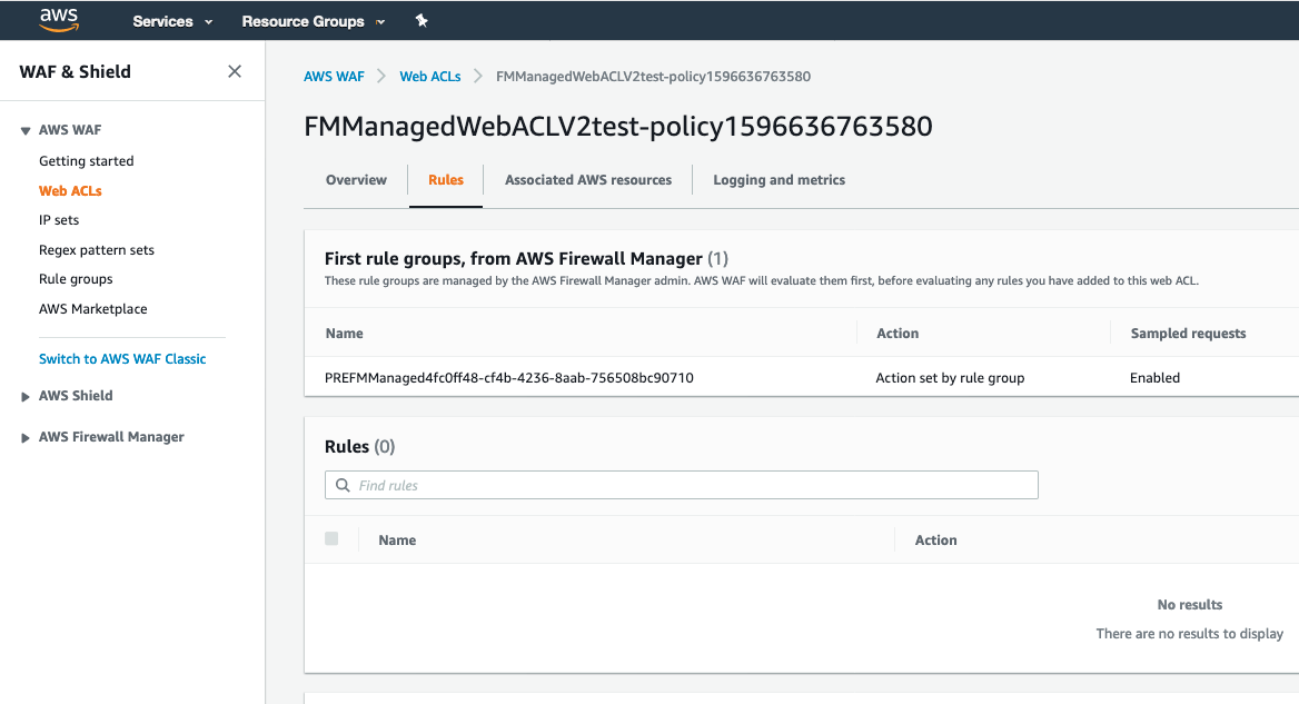
Validation: You can now log in to one of the child accounts to verify whether the resources are created. In our example, all the Application Load Balancers with the tag name DepName:PCI will be associated to this web ACL. You can also add more AWS WAF rules to this web ACL.
 

Figure 8: Reviewing and managing web ACLs in participating child accounts

Figure 8: Reviewing and managing web ACLs in participating child accounts

Firewall Manager logging capability

As part of the AWS WAF capability you want to make sure that logging is enabled with the recently announced feature for centralized logging of your AWS WAF policies. With this logging feature, you get detailed information about traffic within your organization.

The steps are similar to enabling logging for AWS WAF, and consists of two steps. In the first step, Amazon Kinesis Data Firehose is used to capture logs from your policy’s web ACLs to a configured storage destination through the HTTPS endpoint. In the second step, you enable logging in a Firewall Manager policy and select the Firehose stream you created in the first step.

Step 1: Set up a new Kinesis Data Firehose delivery stream

Amazon Kinesis Data Firehose is a fully managed service for delivering real-time streaming data to destinations such as Amazon Simple Storage Service (Amazon S3), Amazon Elasticsearch Service (ES), Splunk, and Amazon Redshift. With Kinesis Data Firehose, you don’t need to write applications or manage resources. You configure your data producers to send data to Kinesis Data Firehose, and it automatically delivers the data to the destination that you specified. You can also configure Kinesis Data Firehose to transform your data before delivering it.

To set up the delivery stream

  1. In the AWS Management Console, using your Firewall Manager administrator account, open the Amazon Kinesis Data Firehose service and choose the button to create a new delivery stream.
    1. For Delivery stream name, enter a name for your new stream that starts with aws-waf-logs- as shown in figure 9. AWS WAF filters all streams starting with the keyword aws-waf-logs when it displays the delivery streams. Note the name of your stream since you’ll need it again later in the walkthrough.
    2. For Source, choose Direct PUT, since AWS WAF logs will be the source in this walkthrough.
    3. We recommend that you also enable server-side encryption. You can either choose to use AWS-owned keys or the customer-managed keys. In this example, we have chosen AWS owned Customer master keys (CMKs). If you have your own CMK’s, you can select the 2nd option of the customer-managed keys and pick your corresponding key from the dropdown list.
       
      Figure 9: Setting the source for the Kinesis Data Firehose delivery stream

      Figure 9: Setting the source for the Kinesis Data Firehose delivery stream

  2. Next, you have the option to enable AWS Lambda if you need to transform your data before transferring it to your destination. (You can learn more about data transformation in the Amazon Kinesis Data Firehose documentation.) In this walkthrough, there are no transformations that need to be performed, so for Data transformation, choose Disabled. You also have the option to convert the JSON object to Apache Parquet or Apache ORC format for better query performance. In this example, for Record format conversion, choose Disabled. Figure 10 shows these options.
     
    Figure 10: Setting data transformation and format conversion

    Figure 10: Setting data transformation and format conversion

  3. On the Select destination screen, for Destination, choose Amazon S3, as shown in figure 11.
    1. For the S3 destination, you can either enter the name of an existing S3 bucket or create a new S3 bucket. Note the name of the S3 bucket, since you’ll need the bucket name in a later step in this walkthrough.
    2. (Optional) Set the S3 prefix and error bucket for logs.
       
      Figure 11: Selecting the destination

      Figure 11: Selecting the destination

    3. On the Configure Settings screen, shown in figure 12, choose other S3 options, such as encryption and compression, and creation of an IAM role for granting access to the Firehose delivery stream.
      1. You can leave the default values for S3 buffer values. We also recommend enabling compression and encryption.
      2. Either choose the option to create a new IAM role, or choose an existing role if you’ve already created one.
      Figure 12: Setting S3 options and IAM role

      Figure 12: Setting S3 options and IAM role

  4. In the next screen, review all the options you selected and choose the Create Delivery Stream button to create a Kinesis Data Firehose delivery stream.

Step 2: Enable logging for an AWS WAF policy

In this step, you configure Firewall Manager policy to direct the log ingestion to the Kinesis Data Firehose delivery stream that you created in the previous step.

To enable logging for an AWS WAF policy

  1. On the AWS Management Console, search for AWS Firewall Manager and in the navigation pane, choose Security Policies.
  2. Choose the AWS WAF policy that you want to enable logging for, and on the Policy details tab, in the Policy rules section, choose Edit. For Logging configuration status, choose Enabled.
  3. Choose the Kinesis Data Firehose that you created for your logging. You must choose a firehose that begins with “aws-waf-logs-”.
     
    Figure 13: Enable Firewall Manager logs

    Figure 13: Enable Firewall Manager logs

  4. Review your settings, and then choose Save to save your changes to the policy.

    Note: Firewall Manager supports this option for the latest version of AWS WAF, but not for AWS WAF Classic.

With these two steps, you now have logging enabled for your Firewall Manager policies.

Deploy Firewall Manager policy with a CloudFormation template

In this section, we provide you with an example CloudFormation template that deploys Firewall Manager policy with a rule group that consists of both an AWS Managed rule set and a custom AWS WAF rule. As a part of the custom AWS WAF rule, this template creates an IP set in which you specify the list of IP addresses from which you want to block traffic. It also creates a rule with an AND statement that blocks cross-site scripting requests and requests that originate from the IP addresses that you specified. You will also notice that this rule is applied to specific accounts that are entered in the parameters as comma-delimited values. Out of many available AWS Managed Rules, we used two rules: AWSManagedRulesCommonRuleSet and AWSManagedRulesSQLiRuleSet. For the former rule, we set the override action to count, which means the requests won’t be blocked but will be counted for further investigation. The latter rule contains rules to block request patterns associated with exploitation of SQL databases, such as SQL injection attacks. This can help prevent remote injection of unauthorized queries.

As a best practice, before using a rule group in production, test it in a non-production environment, with the action override set to count. Evaluate the rule group using Amazon CloudWatch metrics combined with AWS WAF sampled requests or AWS WAF logs. When you’re satisfied that the rule group does what you want, remove the override on the group.

To deploy the CloudFormation template

  1. Copy the following template code and save it in a file named deploy-firewall-manager-policy.yaml.
    Description: Create IPSet, RuleGroup and Firewall Manager Policy. Firewall Policy contains two AWS managed rule groups and one custom rule group.
    Parameters:
      BlockIpAddressCIDR:
        Type: CommaDelimitedList
        Description: "Enter IP Address range by using CIDR notation separated by comma to block incoming traffic originating from them. For eg: To specify the IPV4 address 192.0.2.44 type 192.0.2.44/32 or 10.0.2.0/24"
      AWSAccountIds:
        Type: CommaDelimitedList
        Description: "Enter AWS Account IDs separated by comma in which you want to apply Firewall Manager policy"
    
    Resources:
      WAFIPSetFMS:
          Type: 'AWS::WAFv2::IPSet'
          Properties:
            Description: Block ranges of IP addresses using this IP Set
            Name: WAFIPSetFMS
            Scope: REGIONAL
            IPAddressVersion: IPV4	
            Addresses: !Ref BlockIpAddressCIDR
      RuleGroupXssFMS:
        Type: 'AWS::WAFv2::RuleGroup'
        DependsOn: WAFIPSetFMS
        Properties: 
          Capacity: 500
          Description: AWS WAF Rule Group to block web requests that contain cross site scripting injection attacks and originate from specific IP ranges.
          Name: RuleGroupXssFMS
          Scope: REGIONAL
          VisibilityConfig:
              SampledRequestsEnabled: true
              CloudWatchMetricsEnabled: true
              MetricName: RuleGroupXssFMS
          Rules: 
            - Name: xssException
              Priority: 0
              Action:
                Block: {}
              VisibilityConfig:
                  SampledRequestsEnabled: true
                  CloudWatchMetricsEnabled: true
                  MetricName: xssException
              Statement:
                AndStatement:
                  Statements:
                  - XssMatchStatement:
                      FieldToMatch:
                        Body: {}
                      TextTransformations:
                      - Type: HTML_ENTITY_DECODE
                        Priority: 0
                      - Type: LOWERCASE
                        Priority: 1
                  - IPSetReferenceStatement:
                      Arn: !GetAtt WAFIPSetFMS.Arn
      PolicyWAFv2:
        Type: AWS::FMS::Policy
        Properties:
          ExcludeResourceTags: false
          PolicyName: WAF-Policy
          IncludeMap: 
            ACCOUNT: !Ref AWSAccountIds
          RemediationEnabled: true
          ResourceType: AWS::ElasticLoadBalancingV2::LoadBalancer 
          SecurityServicePolicyData: 
            Type: WAFV2
            ManagedServiceData: !Sub '{"type":"WAFV2", 
                                      "preProcessRuleGroups":[{ 
                                      "ruleGroupType":"RuleGroup",
                                      "ruleGroupArn":"${RuleGroupXssFMS.Arn}",
                                      "overrideAction":{"type":"NONE"}},{
                                      "managedRuleGroupIdentifier":{
                                      "managedRuleGroupName":"AWSManagedRulesCommonRuleSet", 
                                      "vendorName":"AWS"},
                                      "overrideAction":{"type":"COUNT"}, 
                                      "excludeRules":[],"ruleGroupType":"ManagedRuleGroup"},{
                                      "managedRuleGroupIdentifier":{
                                      "managedRuleGroupName":"AWSManagedRulesSQLiRuleSet", 
                                      "vendorName":"AWS"},
                                      "overrideAction":{"type":"NONE"}, 
                                      "excludeRules":[],"ruleGroupType":"ManagedRuleGroup"}],
                                      "postProcessRuleGroups":[],
                                      "defaultAction":{"type":"BLOCK"}}'


  2. Execute the following AWS CLI command to deploy the stack. If you haven’t configured AWS CLI, refer to this quickstart.
    aws cloudformation create-stack --stack-name firewall-manager-policy-stack \
          --template-body file://deploy-firewall-manager-policy.yaml \
          --parameters \
    ParameterKey=BlockIpAddressCIDR,ParameterValue=<Enter-BlockIpAddressCIDR>
    ParameterKey= AWSAccountIds,ParameterValue=<Enter-AWSAccountIds>
    

Pricing

As of today, price per AWS WAF protection policy per Region is $100.00. To get an overall idea on pricing, we recommend that you review this AWS Firewall Manager pricing guide that covers a few scenarios.

AWS WAF charges based on the number of web access control lists (web ACLs) that you create, the number of rules that you add per web ACL, and the number of web requests that you receive. There are no upfront commitments. Learn more about AWS WAF pricing.

There is no additional charge for using AWS Managed Rules for AWS WAF. When you subscribe to a Managed Rule Group provided by an AWS Marketplace seller, you will be charged additional fees based on the price set by the seller.

AWS Shield Advanced customers can use Firewall Manager to apply AWS Shield Advanced and AWS WAF protections across their entire organization at no additional cost.

Conclusion

This blog post describes how you can create Firewall Manager policies with the new version of AWS WAF rules, by using the web console or AWS CloudFormation. You can also create these rules by using the command line interface (CLI), or programmatically with the SDK and other similar scripting tools. Using both AWS WAF and Firewall Manager, you can create a deployment strategy to safeguard all your accounts centrally at the organization level, and also choose to automatically remediate the AWS WAF rules if anything is changed after deployment.

For further reading, see the AWS Firewall Manager Developer Guide.

If you have feedback about this post, submit comments in the Comments section below. If you have questions about this post, start a new thread on the AWS Firewall Manager forum or contact AWS Support.

Want more AWS Security how-to content, news, and feature announcements? Follow us on Twitter.

Author

Umesh Kumar Ramesh

Umesh is a Senior Cloud Infrastructure Architect with AWS who delivers proof-of-concept projects and topical workshops, and leads implementation projects. He holds a bachelor’s degree in Computer Science & Engineering from the National Institute of Technology, Jamshedpur (India). Outside of work, he enjoys watching documentaries, biking, practicing meditation and discussing spirituality.

Author

Mahek Pavagadhi

Mahek is a Cloud Infrastructure Architect at AWS in San Francisco, CA. She has a master’s degree in Software Engineering with a major in Cloud Computing. She is passionate about cloud services and building solutions with it. Outside of work, she is an avid traveler who loves to explore local cafeterias.

120 AWS services achieve HITRUST certification

Post Syndicated from Hadis Ali original https://aws.amazon.com/blogs/security/120-aws-services-achieve-hitrust-certification/

We’re excited to announce that 120 Amazon Web Services (AWS) services are certified for the HITRUST Common Security Framework (CSF) for the 2020 cycle.

The full list of AWS services that were audited by a third-party assessor and certified under HITRUST CSF is available on our Services in Scope by Compliance Program page. You can view and download our HITRUST CSF certification from AWS Artifact.

AWS HITRUST CSF certification is available for customer inheritance

You don’t have to assess the inherited controls, because AWS already has! You can deploy environments onto AWS and inherit our HITRUST CSF certification provided that you use only in-scope services and apply the controls detailed on the HITRUST website that you are responsible for implementing.

The HITRUST certification allows you, as an AWS customer, to tailor your security control baselines to a variety of factors including, but not limited to, regulatory requirements and organization type. The HITRUST CSF is widely adopted by leading organizations in a variety of industries in their approach to security and privacy. Visit the HITRUST website for more information.

As always, we value your feedback and questions and are committed to helping you achieve and maintain the highest standard of security and compliance. Feel free to contact the team through AWS Compliance Contact Us. If you have feedback about this post, submit comments in the Comments section below.

Want more AWS Security how-to content, news, and feature announcements? Follow us on Twitter.

Author

Hadis Ali

Hadis is a Security and Privacy Manager at Amazon Web Services. He leads multiple security and privacy initiatives within AWS Security Assurance. Hadis holds Bachelor’s degrees in Accounting and Information Systems from the University of Washington.

Creating a source to Lakehouse data replication pipe using Apache Hudi, AWS Glue, AWS DMS, and Amazon Redshift

Post Syndicated from Vishal Pathak original https://aws.amazon.com/blogs/big-data/creating-a-source-to-lakehouse-data-replication-pipe-using-apache-hudi-aws-glue-aws-dms-and-amazon-redshift/

Most customers have their applications backed by various sql and nosql systems on prem and on cloud. Since the data is in various independent systems, customers struggle to derive meaningful info by combining data from all of these sources. Hence, customers create data lakes to bring their data in a single place.

Typically, a replication tool such as AWS Database Migration Service (AWS DMS) can replicate the data from your source systems to Amazon Simple Storage Service (Amazon S3). When the data is in Amazon S3, customers process it based on their requirements. A typical requirement is to sync the data in Amazon S3 with the updates on the source systems. Although it’s easy to apply updates on a relational database management system (RDBMS) that backs an online source application, it’s tough to apply this change data capture (CDC) process on your data lakes. Apache Hudi is a good way to solve this problem. Currently, you can use Hudi on Amazon EMR to create Hudi tables.

In this post, we use Apache Hudi to create tables in the AWS Glue Data Catalog using AWS Glue jobs. AWS Glue is a fully managed extract, transform, and load (ETL) service that makes it easy to prepare and load your data for analytics. This post enables you to take advantage of the serverless architecture of AWS Glue while upserting data in your data lake, hassle-free.

To write to Hudi tables using AWS Glue jobs, we use a JAR file created using open-source Apache Hudi. This JAR file is used as a dependency in the AWS Glue jobs created through the AWS CloudFormation template provided in this post. Steps to create the JAR file are included in the appendix.

The following diagram illustrates the architecture the CloudFormation template implements.

Prerequisites

The CloudFormation template requires you to select an Amazon Elastic Compute Cloud (Amazon EC2) key pair. This key is configured on an EC2 instance that lives in the public subnet. We use this EC2 instance to get to the Aurora cluster that lives in the private subnet. Make sure you have a key in the Region where you deploy the template. If you don’t have one, you can create a new key pair.

Solution overview

The following are the high-level implementation steps:

  1. Create a CloudFormation stack using the provided template.
  2. Connect to the Amazon Aurora cluster used as a source for this post.
  3. Run InitLoad_TestStep1.sql, in the source Amazon Aurora cluster, to create a schema and a table.

AWS DMS replicates the data from the Aurora cluster to the raw S3 bucket. AWS DMS supports a variety of sources.
The CloudFormation stack creates an AWS Glue job (HudiJob) that is scheduled to run at a frequency set in the ScheduleToRunGlueJob parameter of the CloudFormation stack. This job reads the data from the raw S3 bucket, writes to the Curated S3 bucket, and creates a Hudi table in the Data Catalog. The job also creates an Amazon Redshift external schema in the Amazon Redshift cluster created by the CloudFormation stack.

  1. You can now query the Hudi table in Amazon Athena or Amazon Redshift. Visit Creating external tables for data managed in Apache Hudi or Considerations and Limitations to query Apache Hudi datasets in Amazon Athena for details.
  2. Run IncrementalUpdatesAndInserts_TestStep2.sql on the source Aurora cluster.

This incremental data is also replicated to the raw S3 bucket through AWS DMS. HudiJob picks up the incremental data, using AWS Glue bookmarks, and applies it to the Hudi table created earlier.

  1. You can now query the changed data.

Creating your CloudFormation stack

Click on the Launch Stack button to get started and provide the following parameters:

Parameter Description
VpcCIDR CIDR range for the VPC.
PrivateSubnet1CIDR CIDR range for the first private subnet.
PrivateSubnet2CIDR CIDR range for the second private subnet.
PublicSubnetCIDR CIDR range for the public subnet.
AuroraDBMasterUserPassword Primary user password for the Aurora cluster.
RedshiftDWMasterUserPassword Primary user password for the Amazon Redshift data warehouse.
KeyName The EC2 key pair to be configured in the EC2 instance on the public subnet. This EC2 instance is used to get to the Aurora cluster in the private subnet. Select the value from the dropdown.
ClientIPCIDR Your IP address in CIDR notation. The CloudFormation template creates a security group rule that grants ingress on port 22 to this IP address. On a Mac, you can run the following command to get your IP address: curl ipecho.net/plain ; echo /32
EC2ImageId The image ID used to create the EC2 instance in the public subnet to be a jump box to connect to the source Aurora cluster. If you supply your image ID, the template uses it to create the EC2 instance.
HudiStorageType This is used by the AWS Glue job to determine if you want to create a CoW or MoR storage type table. Enter MoR if you want to create MoR storage type tables.
ScheduleToRunGlueJob The AWS Glue job runs on a schedule to pick the new files and load to the curated bucket. This parameter sets the schedule of the job.
DMSBatchUnloadIntervalInSecs AWS DMS batches the inputs from the source and loads the output to the taw bucket. This parameter defines the frequency in which the data is loaded to the raw bucket.
GlueJobDPUs The number of DPUs that are assigned to the two AWS Glue jobs.

To simplify running the template, your account is given permissions on the key used to encrypt the resources in the CloudFormation template. You can restrict that to the role if desired.

Granting Lake Formation permissions

AWS Lake Formation enables customers to set up fine grained access control for their Datalake. Detail steps to set up AWS Lake Formation can be found here.

Setting up AWS Lake Formation is out of scope for this post. However, if you have Lake Formation configured in the Region where you’re deploying this template, grant Create database permission to the LakeHouseExecuteGlueHudiJobRole role after the CloudFormation stack is successfully created.

This will ensure that you don’t get the following error while running your AWS Glue job.

org.apache.spark.sql.AnalysisException: org.apache.hadoop.hive.ql.metadata.HiveException: MetaException(message:Insufficient Lake Formation permission(s) on global_temp

Similarly grant Describe permission to the LakeHouseExecuteGlueHudiJobRole role on default database.

This will ensure that you don’t get the following error while running your AWS Glue job.

AnalysisException: 'java.lang.RuntimeException: MetaException(message:Unable to verify existence of default database: com.amazonaws.services.glue.model.AccessDeniedException: Insufficient Lake Formation permission(s) on default (Service: AWSGlue; Status Code: 400; Error Code: AccessDeniedException;

Connecting to source Aurora cluster

To connect to source Aurora cluster using SQL Workbench, complete the following steps:

  1. On SQL Workbench, under File, choose Connect window.

  1. Choose Manage Drivers.

  1. Choose PostgreSQL.
  2. For Library, use the driver JAR file.
  3. For Classname, enter org.postgresql.Driver.
  4. For Sample URL, enter jdbc:postgresql://host:port/name_of_database.

  1. Click the Create a new connection profile button.
  2. For Driver, choose your new PostgreSQL driver.
  3. For URL, enter lakehouse_source_db after port/.
  4. For Username, enter postgres.
  5. For Password, enter the same password that you used for the AuroraDBMasterUserPassword parameter while creating the CloudFormation stack.
  6. Choose SSH.
  7. On the Outputs tab of your CloudFormation stack, copy the IP address next to PublicIPOfEC2InstanceForTunnel and enter it for SSH hostname.
  8. For SSH port, enter 22.
  9. For Username, enter ec2-user.
  10. For Private key file, enter the private key for the public key chosen in the KeyName parameter of the CloudFormation stack.
  11. For Local port, enter any available local port number.
  12. On the Outputs tab of your stack, copy the value next to EndpointOfAuroraCluster and enter it for DB hostname.
  13. For DB port, enter 5432.
  14. Select Rewrite JDBC URL.


Checking the Rewrite JDBC URL checkbox will automatically feed in the value of host and port in the URL text box as shown below.

  1. Test the connection and make sure that you get a message that the connection was successful.


Troubleshooting

Complete the following steps if you receive this message: Could not initialize SSH tunnel: java.net.ConnectException: Operation timed out (Connection timed out)

  1. Go to your CloudFormation stack and search for LakeHouseSecurityGroup under Resources .
  2. Choose the link in the Physical ID.

  1. Select your security group.
  2. From the Actions menu, choose Edit inbound rules.

  1. Look for the rule with the description:Rule to allow connection from the SQL client to the EC2 instance used as jump box for SSH tunnel
  2. From the Source menu, choose My IP.
  3. Choose Save rules.

  1. Test the connection from your SQL Workbench again and make sure that you get a successful message.

Running the initial load script

You’re now ready to run the InitLoad_TestStep1.sql script to create some test data.

  1. Open InitLoad_TestStep1.sql in your SQL client and run it.

The output shows that 11 statements have been run.

AWS DMS replicates these inserts to your raw S3 bucket at the frequency set in the DMSBatchUnloadIntervalInSecs parameter of your CloudFormation stack.

  1. On the AWS DMS console, choose the lakehouse-aurora-src-to-raw-s3-tgt task:
  2. On the Table statistics tab, you should see the seven full load rows of employee_details have been replicated.

The lakehouse-aurora-src-to-raw-s3-tgt replication task has the following table mapping with transformation to add a schema name and a table name as additional columns:

{
   "rules":[
      {
         "rule-type":"selection",
         "rule-id":"1",
         "rule-name":"1",
         "object-locator":{
            "schema-name":"human_resources",
            "table-name":"%"
         },
         "rule-action":"include",
         "filters":[
            
         ]
      },
      {
         "rule-type":"transformation",
         "rule-id":"2",
         "rule-name":"2",
         "rule-target":"column",
         "object-locator":{
            "schema-name":"%",
            "table-name":"%"
         },
         "rule-action":"add-column",
         "value":"schema_name",
         "expression":"$SCHEMA_NAME_VAR",
         "data-type":{
            "type":"string",
            "length":50
         }
      },
      {
         "rule-type":"transformation",
         "rule-id":"3",
         "rule-name":"3",
         "rule-target":"column",
         "object-locator":{
            "schema-name":"%",
            "table-name":"%"
         },
         "rule-action":"add-column",
         "value":"table_name",
         "expression":"$TABLE_NAME_VAR",
         "data-type":{
            "type":"string",
            "length":50
         }
      }
   ]
}

These settings put the name of the source schema and table as two additional columns in the output Parquet file of AWS DMS.
These columns are used in the AWS Glue HudiJob to find out the tables that have new inserts, updates, or deletes.

  1. On the Resources tab of the CloudFormation stack, locate RawS3Bucket.
  2. Choose the Physical ID link.

  1. Navigate to human_resources/employee_details.

The LOAD00000001.parquet file is created under human_resources/employee_details. (The name of your raw bucket is different from the following screenshot).

You can also see the time of creation of this file. You should have at least one successful run of the AWS Glue job (HudiJob) after this time for the Hudi table to be created. The AWS Glue job is configured to load this data into the curated bucket at the frequency set in the ScheduleToRunGlueJob parameter of your CloudFormation stack. The default is 5 minutes.

AWS Glue job HudiJob

The following code is the script for HudiJob:

import sys
import os
import json

from pyspark.context import SparkContext
from pyspark.sql.session import SparkSession
from pyspark.sql.functions import concat, col, lit, to_timestamp

from awsglue.utils import getResolvedOptions
from awsglue.context import GlueContext
from awsglue.job import Job
from awsglue.dynamicframe import DynamicFrame

import boto3
from botocore.exceptions import ClientError

args = getResolvedOptions(sys.argv, ['JOB_NAME'])

spark = SparkSession.builder.config('spark.serializer','org.apache.spark.serializer.KryoSerializer').getOrCreate()
glueContext = GlueContext(spark.sparkContext)
job = Job(glueContext)
job.init(args['JOB_NAME'], args)
logger = glueContext.get_logger()

logger.info('Initialization.')
glueClient = boto3.client('glue')
ssmClient = boto3.client('ssm')
redshiftDataClient = boto3.client('redshift-data')

logger.info('Fetching configuration.')
region = os.environ['AWS_DEFAULT_REGION']

curatedS3BucketName = ssmClient.get_parameter(Name='lakehouse-curated-s3-bucket-name')['Parameter']['Value']
rawS3BucketName = ssmClient.get_parameter(Name='lakehouse-raw-s3-bucket-name')['Parameter']['Value']
hudiStorageType = ssmClient.get_parameter(Name='lakehouse-hudi-storage-type')['Parameter']['Value']

dropColumnList = ['db','table_name','Op']

logger.info('Getting list of schema.tables that have changed.')
changeTableListDyf = glueContext.create_dynamic_frame_from_options(connection_type = 's3', connection_options = {'paths': ['s3://'+rawS3BucketName], 'groupFiles': 'inPartition', 'recurse':True}, format = 'parquet', format_options={}, transformation_ctx = 'changeTableListDyf')

logger.info('Processing starts.')
if(changeTableListDyf.count() > 0):
    logger.info('Got new files to process.')
    changeTableList = changeTableListDyf.toDF().select('schema_name','table_name').distinct().rdd.map(lambda row : row.asDict()).collect()

    for dbName in set([d['schema_name'] for d in changeTableList]):
        spark.sql('CREATE DATABASE IF NOT EXISTS ' + dbName)
        redshiftDataClient.execute_statement(ClusterIdentifier='lakehouse-redshift-cluster', Database='lakehouse_dw', DbUser='rs_admin', Sql='CREATE EXTERNAL SCHEMA IF NOT EXISTS ' + dbName + ' FROM DATA CATALOG DATABASE \'' + dbName + '\' REGION \'' + region + '\' IAM_ROLE \'' + boto3.client('iam').get_role(RoleName='LakeHouseRedshiftGlueAccessRole')['Role']['Arn'] + '\'')

    for i in changeTableList:
        logger.info('Looping for ' + i['schema_name'] + '.' + i['table_name'])
        dbName = i['schema_name']
        tableNameCatalogCheck = ''
        tableName = i['table_name']
        if(hudiStorageType == 'MoR'):
            tableNameCatalogCheck = i['table_name'] + '_ro' #Assumption is that if _ro table exists then _rt table will also exist. Hence we are checking only for _ro.
        else:
            tableNameCatalogCheck = i['table_name'] #The default config in the CF template is CoW. So assumption is that if the user hasn't explicitly requested to create MoR storage type table then we will create CoW tables. Again, if the user overwrites the config with any value other than 'MoR' we will create CoW storage type tables.
        isTableExists = False
        isPrimaryKey = False
        isPartitionKey = False
        primaryKey = ''
        partitionKey = ''
        try:
            glueClient.get_table(DatabaseName=dbName,Name=tableNameCatalogCheck)
            isTableExists = True
            logger.info(dbName + '.' + tableNameCatalogCheck + ' exists.')
        except ClientError as e:
            if e.response['Error']['Code'] == 'EntityNotFoundException':
                isTableExists = False
                logger.info(dbName + '.' + tableNameCatalogCheck + ' does not exist. Table will be created.')
        try:
            table_config = json.loads(ssmClient.get_parameter(Name='lakehouse-table-' + dbName + '.' + tableName)['Parameter']['Value'])
            try:
                primaryKey = table_config['primaryKey']
                isPrimaryKey = True
                logger.info('Primary key:' + primaryKey)
            except KeyError as e:
                isPrimaryKey = False
                logger.info('Primary key not found. An append only glueparquet table will be created.')
            try:
                partitionKey = table_config['partitionKey']
                isPartitionKey = True
                logger.info('Partition key:' + partitionKey)
            except KeyError as e:
                isPartitionKey = False
                logger.info('Partition key not found. Partitions will not be created.')
        except ClientError as e:    
            if e.response['Error']['Code'] == 'ParameterNotFound':
                isPrimaryKey = False
                isPartitionKey = False
                logger.info('Config for ' + dbName + '.' + tableName + ' not found in parameter store. Non partitioned append only table will be created.')

        inputDyf = glueContext.create_dynamic_frame_from_options(connection_type = 's3', connection_options = {'paths': ['s3://' + rawS3BucketName + '/' + dbName + '/' + tableName], 'groupFiles': 'none', 'recurse':True}, format = 'parquet',transformation_ctx = tableName)
        
        inputDf = inputDyf.toDF().withColumn('update_ts_dms',to_timestamp(col('update_ts_dms')))
        
        targetPath = 's3://' + curatedS3BucketName + '/' + dbName + '/' + tableName

        morConfig = {'hoodie.datasource.write.storage.type': 'MERGE_ON_READ', 'hoodie.compact.inline': 'false', 'hoodie.compact.inline.max.delta.commits': 20, 'hoodie.parquet.small.file.limit': 0}

        commonConfig = {'className' : 'org.apache.hudi', 'hoodie.datasource.hive_sync.use_jdbc':'false', 'hoodie.datasource.write.precombine.field': 'update_ts_dms', 'hoodie.datasource.write.recordkey.field': primaryKey, 'hoodie.table.name': tableName, 'hoodie.consistency.check.enabled': 'true', 'hoodie.datasource.hive_sync.database': dbName, 'hoodie.datasource.hive_sync.table': tableName, 'hoodie.datasource.hive_sync.enable': 'true'}

        partitionDataConfig = {'hoodie.datasource.write.partitionpath.field': partitionKey, 'hoodie.datasource.hive_sync.partition_extractor_class': 'org.apache.hudi.hive.MultiPartKeysValueExtractor', 'hoodie.datasource.hive_sync.partition_fields': partitionKey}
                     
        unpartitionDataConfig = {'hoodie.datasource.hive_sync.partition_extractor_class': 'org.apache.hudi.hive.NonPartitionedExtractor', 'hoodie.datasource.write.keygenerator.class': 'org.apache.hudi.keygen.NonpartitionedKeyGenerator'}
        
        incrementalConfig = {'hoodie.upsert.shuffle.parallelism': 20, 'hoodie.datasource.write.operation': 'upsert', 'hoodie.cleaner.policy': 'KEEP_LATEST_COMMITS', 'hoodie.cleaner.commits.retained': 10}
        
        initLoadConfig = {'hoodie.bulkinsert.shuffle.parallelism': 3, 'hoodie.datasource.write.operation': 'bulk_insert'}
        
        deleteDataConfig = {'hoodie.datasource.write.payload.class': 'org.apache.hudi.common.model.EmptyHoodieRecordPayload'}

        if(hudiStorageType == 'MoR'):
            commonConfig = {**commonConfig, **morConfig}
            logger.info('MoR config appended to commonConfig.')
        
        combinedConf = {}

        if(isPrimaryKey):
            logger.info('Going the Hudi way.')
            if(isTableExists):
                logger.info('Incremental load.')
                outputDf = inputDf.filter("Op != 'D'").drop(*dropColumnList)
                if outputDf.count() > 0:
                    logger.info('Upserting data.')
                    if (isPartitionKey):
                        logger.info('Writing to partitioned Hudi table.')
                        outputDf = outputDf.withColumn(partitionKey,concat(lit(partitionKey+'='),col(partitionKey)))
                        combinedConf = {**commonConfig, **partitionDataConfig, **incrementalConfig}
                        outputDf.write.format('org.apache.hudi').options(**combinedConf).mode('Append').save(targetPath)
                    else:
                        logger.info('Writing to unpartitioned Hudi table.')
                        combinedConf = {**commonConfig, **unpartitionDataConfig, **incrementalConfig}
                        outputDf.write.format('org.apache.hudi').options(**combinedConf).mode('Append').save(targetPath)
                outputDf_deleted = inputDf.filter("Op = 'D'").drop(*dropColumnList)
                if outputDf_deleted.count() > 0:
                    logger.info('Some data got deleted.')
                    if (isPartitionKey):
                        logger.info('Deleting from partitioned Hudi table.')
                        outputDf_deleted = outputDf_deleted.withColumn(partitionKey,concat(lit(partitionKey+'='),col(partitionKey)))
                        combinedConf = {**commonConfig, **partitionDataConfig, **incrementalConfig, **deleteDataConfig}
                        outputDf_deleted.write.format('org.apache.hudi').options(**combinedConf).mode('Append').save(targetPath)
                    else:
                        logger.info('Deleting from unpartitioned Hudi table.')
                        combinedConf = {**commonConfig, **unpartitionDataConfig, **incrementalConfig, **deleteDataConfig}
                        outputDf_deleted.write.format('org.apache.hudi').options(**combinedConf).mode('Append').save(targetPath)
            else:
                outputDf = inputDf.drop(*dropColumnList)
                if outputDf.count() > 0:
                    logger.info('Inital load.')
                    if (isPartitionKey):
                        logger.info('Writing to partitioned Hudi table.')
                        outputDf = outputDf.withColumn(partitionKey,concat(lit(partitionKey+'='),col(partitionKey)))
                        combinedConf = {**commonConfig, **partitionDataConfig, **initLoadConfig}
                        outputDf.write.format('org.apache.hudi').options(**combinedConf).mode('Overwrite').save(targetPath)
                    else:
                        logger.info('Writing to unpartitioned Hudi table.')
                        combinedConf = {**commonConfig, **unpartitionDataConfig, **initLoadConfig}
                        outputDf.write.format('org.apache.hudi').options(**combinedConf).mode('Overwrite').save(targetPath)
        else:
            if (isPartitionKey):
                logger.info('Writing to partitioned glueparquet table.')
                sink = glueContext.getSink(connection_type = 's3', path= targetPath, enableUpdateCatalog = True, updateBehavior = 'UPDATE_IN_DATABASE', partitionKeys=[partitionKey])
            else:
                logger.info('Writing to unpartitioned glueparquet table.')
                sink = glueContext.getSink(connection_type = 's3', path= targetPath, enableUpdateCatalog = True, updateBehavior = 'UPDATE_IN_DATABASE')
            sink.setFormat('glueparquet')
            sink.setCatalogInfo(catalogDatabase = dbName, catalogTableName = tableName)
            outputDyf = DynamicFrame.fromDF(inputDf.drop(*dropColumnList), glueContext, 'outputDyf')
            sink.writeFrame(outputDyf)

job.commit()

Hudi tables need a primary key to perform upserts. Hudi tables can also be partitioned based on a certain key. We get the names of the primary key and the partition key from AWS Systems Manager Parameter Store.

The HudiJob script looks for an AWS Systems Manager Parameter with the naming format lakehouse-table-<schema_name>.<table_name>. It compares the name of the parameter with the name of the schema and table columns, added by AWS DMS, to get the primary key and the partition key for the Hudi table.

The CloudFormation template creates lakehouse-table-human_resources.employee_details AWS Systems Manager Parameter, as shown on the Resources tab.

If you choose the Physical ID link, you can locate the value of the AWS Systems Manager Parameter. The AWS Systems Manager Parameter has {"primaryKey": "emp_no", "partitionKey": "department"} value in it.

Because of the value in the lakehouse-table-human_resources.employee_details AWS Systems Manager Parameter, the AWS Glue script creates a human_resources.employee_details Hudi table partitioned on the department column for the employee_details table created in the source using the InitLoad_TestStep1.sql script. The HudiJob also uses the emp_no column as the primary key for upserts.

If you reuse this CloudFormation template and create your own table, you have to create an associated AWS Systems Manager Parameter with the naming convention lakehouse-table-<schema_name>.<table_name>. Keep in mind the following:

  • If you don’t create a parameter, the script creates an unpartitioned glueparquet append-only table.
  • If you create a parameter that only has the primaryKey part in the value, the script creates an unpartitioned Hudi table.
  • If you create a parameter that only has the partitionKey part in the value, the script creates a partitioned glueparquet append-only table.

If you have too many tables to replicate, you can also store the primary key and partition key configuration in Amazon DynamoDB or Amazon S3 and change the code accordingly.

In the InitLoad_TestStep1.sql script, replica identity for human_resources.employee_details table is set to full. This makes sure that AWS DMS transfers the full delete record to Amazon S3. Having this delete record is important for the HudiJob script to delete the record from the Hudi table. A full delete record from AWS DMS for the human_resources.employee_details table looks like the following:

{ "Op": "D", "update_ts_dms": "2020-10-25 07:57:48.589284", "emp_no": 3, "name": "Jeff", "department": "Finance", "city": "Tokyo", "salary": 55000, "schema_name": "human_resources", "table_name": "employee_details"}

The schema_name, and table_name columns are added by AWS DMS because of the task configuration shared previously.update_ts_dms has been set as the value for TimestampColumnName S3 setting in AWS DMS S3 Endpoint.Op is added by AWS DMS for cdc and it indicates source DB operations in migrated S3 data.

We also set spark.serializer in the script. This setting is required for Hudi.

In HudiJob script, you can also find a few Python dict that store various Hudi configuration properties. These configurations are just for demo purposes; you have to adjust them based on your workload. For more information about Hudi configurations, see Configurations.

HudiJob is scheduled to run every 5 minutes by default. The frequency is set by the ScheduleToRunGlueJob parameter of the CloudFormation template. Make sure that you successfully run HudiJob at least one time after the source data lands in the raw S3 bucket. The screenshot in Step 6 of Running the initial load script section confirms that AWS DMS put the LOAD00000001.parquet file in the raw bucket at 11:54:41 AM and following screenshot confirms that the job execution started at 11:55 AM.

The job creates a Hudi table in the AWS Glue Data Catalog (see the following screenshot). The table is partitioned on the department column.

Granting AWS Lake Formation permissions

If you have AWS Lake Formation enabled, make sure that you grant Select permission on the human_resources.employee_details table to the role/user used to run Athena query. Similarly, you also have to grant Select permission on the human_resources.employee_details table to the LakeHouseRedshiftGlueAccessRole role so you can query human_resources.employee_details in Amazon Redshift.

Grant Drop permission on the human_resources database to LakeHouseExecuteLambdaFnsRole so that the template can delete the database when you delete the template. Also, the CloudFormation template does not roll back any AWS Lake Formation grants or changes that are manually applied.

Granting access to KMS key

The curated S3 bucket is encrypted by lakehouse-key, which is an AWS Key Management Service (AWS KMS) customer managed key created by AWS CloudFormation template.

To run the query in Athena, you have to add the ARN of the role/user used to run the Athena query in the Allow use of the key section in the key policy.

This will ensure that you don’t get com.amazonaws.services.s3.model.AmazonS3Exception: Access Denied (Service: Amazon S3; Status Code: 403; Error Code: AccessDenied; error while running your Athena query.

You might not have to execute the above KMS policy change if you have kept the default of granting access to the AWS account and the role/user used to run Athena query has the necessary KMS related policies attached to it.

Confirming job completion

When HudiJob is complete, you can see the files in the curated bucket.

  1. On the Resources tab, search for CuratedS3Bucket.
  2. Choose the Physical ID link.

The following screenshot shows the timestamp on the initial load.

  1. Navigate to the department=Finance prefix and select the Parquet file.
  2. Choose Select from.
  1. For File format, select Parquet.
  2. Choose Show file preview.

You can see the value of the timestamp in the update_ts_dms column.

Querying the Hudi table

You can now query your data in Amazon Athena or Amazon Redshift.

Querying in Amazon Athena

Query the human_resources.employee_details table in Amazon Athena with the following code:

SELECT emp_no,
         name,
         city,
         salary,
         department,
         from_unixtime(update_ts_dms/1000000,'America/Los_Angeles') update_ts_dms_LA,
         from_unixtime(update_ts_dms/1000000,'UTC') update_ts_dms_UTC         
FROM "human_resources"."employee_details"
ORDER BY emp_no

The timestamp for all the records matches the timestamp in the update_ts_dms column in the earlier screenshot.

Querying in Redshift Spectrum

Read query your table in Redshift Spectrum for Apache Hudi support in Amazon Redshift.

  1. On the Amazon Redshift console, locate lakehouse-redshift-cluster.
  2. Choose Query cluster.

  1. For Database name, enter lakehouse_dw.
  2. For Database user, enter rs_admin.
  3. For Database password, enter the password that you used for the RedshiftDWMasterUserPassword parameter in the CloudFormation template.

  1. Enter the following query for the human_resources.employee_details table:
    SELECT emp_no,
             name,
             city,
             salary,
             department,
             (TIMESTAMP 'epoch' + update_ts_dms/1000000 * interval '1 second') AT TIME ZONE 'utc' AT TIME ZONE 'america/los_angeles' update_ts_dms_LA,
             (TIMESTAMP 'epoch' + update_ts_dms/1000000 * interval '1 second') AT TIME ZONE 'utc' update_ts_dms_UTC
    FROM human_resources.employee_details
    ORDER BY emp_no 

The following screenshot shows the query output.

Running the incremental load script

We now run the IncrementalUpdatesAndInserts_TestStep2.sql script. The output shows that 6 statements were run.

AWS DMS now shows that it has replicated the new incremental changes. The changes are replicated at a frequency set in DMSBatchUnloadIntervalInSecs parameter of the CloudFormation stack.

This creates another Parquet file in the raw S3 bucket.

The incremental updates are loaded into the Hudi table according to the chosen frequency to run the job (the ScheduleToRunGlueJob parameter). The HudiJobscript uses job bookmarks to find out the incremental load so it only processes the new files brought in through AWS DMS.

Confirming job completion

Make sure that HudiJob runs successfully at least one time after the incremental file arrives in the raw bucket. The previous screenshot shows that the incremental file arrived in the raw bucket at 1:18:38 PM and the following screenshot shows that the job started at 1:20 PM.

Querying the changed data

You can now check the table in Athena and Amazon Redshift. Both results show that emp_no 3 is deleted, 8 and 9 have been added, and 2 and 5 have been updated.

The following screenshot shows the results in Athena.

The following screenshot shows the results in Redshift Spectrum.

AWS Glue Job HudiMoRCompactionJob

The CloudFormation template also deploys the AWS Glue job HudiMoRCompactionJob. This job is not scheduled; you only use it if you choose the MoR storage type. To execute the pipe for MoR storage type instead of CoW storage type, delete the CloudFormation stack and create it again. After creation, replace CoW in lakehouse-hudi-storage-type AWS Systems Manager Parameter with MoR.

If you use MoR storage type, the incremental updates are stored in log files. You can’t see the updates in the _ro (read optimized) view, but can see them in the _rt view. Amazon Athena documentation and Amazon Redshift documentation gives more details about support and considerations for Apache Hudi.

To see the incremental data in the _ro view, run the HudiMoRCompactionJob job. For more information about Hudi storage types and views, see Hudi Dataset Storage Types and Storage Types & Views. The following code is an example of the CLI command used to run HudiMoRCompactionJob job:

aws glue start-job-run --job-name HudiMoRCompactionJob --arguments="--DB_NAME=human_resources","--TABLE_NAME=employee_details","--IS_PARTITIONED=true"

You can decide on the frequency of running this job. You don’t have to run the job immediately after the HudiJob. You should run this job when you want the data to be available in the _ro view. You have to pass the schema name and the table name to this script so it knows the table to compact.

Additional considerations

The JAR file we use in this post has not been tested for AWS Glue streaming jobs. Additionally, there are some hardcoded Hudi options in the HudiJob script. These options are set for the sample table that we create for this post. Update the options based on your workload. 

Conclusion

In this post, we created AWS Glue 2.0 jobs that moved the source upserts and deletes into Hudi tables. The code creates tables in the AWS GLue Data Catalog and updates partitions so you don’t have to run the crawlers to update them.

This post simplified your LakeHouse code base by giving you the benefits of Apache Hudi along with serverless AWS Glue. We also showed how to create an source to LakeHouse replication system using AWS Glue, AWS DMS, and Amazon Redshift with minimum overhead.


Appendix

We can write to Hudi tables because of the hudi-spark.jar file that we downloaded to our DependentJarsAndTempS3Bucket S3 bucket with the CloudFormation template. The path to this file is added as a dependency in both the AWS Glue jobs. This file is based on open-source Hudi. To create the JAR file, complete the following steps:

  1. Get Hudi 0.5.3 and unzip it using the following code:
    wget https://github.com/apache/hudi/archive/release-0.5.3.zip
    unzip hudi-release-0.5.3.zip

  2. Edit Hudi pom.xml:
    vi hudi-release-0.5.3/pom.xml

    1. Remove the following code to make the build process faster:
      <module>packaging/hudi-hadoop-mr-bundle</module>
      <module>packaging/hudi-hive-bundle</module>
      <module>packaging/hudi-presto-bundle</module>
      <module>packaging/hudi-utilities-bundle</module>
      <module>packaging/hudi-timeline-server-bundle</module>
      <module>docker/hoodie/hadoop</module>
      <module>hudi-integ-test</module>

    2. Change the versions of all three dependencies of httpcomponents to 4.4.1. The following is the original code:
      <!-- Httpcomponents -->
            <dependency>
              <groupId>org.apache.httpcomponents</groupId>
              <artifactId>fluent-hc</artifactId>
              <version>4.3.2</version>
            </dependency>
            <dependency>
              <groupId>org.apache.httpcomponents</groupId>
              <artifactId>httpcore</artifactId>
              <version>4.3.2</version>
            </dependency>
            <dependency>
              <groupId>org.apache.httpcomponents</groupId>
              <artifactId>httpclient</artifactId>
              <version>4.3.6</version>
            </dependency>

      The following is the replacement code:

      <!-- Httpcomponents -->
            <dependency>
              <groupId>org.apache.httpcomponents</groupId>
              <artifactId>fluent-hc</artifactId>
              <version>4.4.1</version>
            </dependency>
            <dependency>
              <groupId>org.apache.httpcomponents</groupId>
              <artifactId>httpcore</artifactId>
              <version>4.4.1</version>
            </dependency>
            <dependency>
              <groupId>org.apache.httpcomponents</groupId>
              <artifactId>httpclient</artifactId>
              <version>4.4.1</version>
            </dependency>

  3. Build the JAR file:
    mvn clean package -DskipTests -DskipITs -f <Full path of the hudi-release-0.5.3 dir>

  4. You can now get the JAR from the following location:
hudi-release-0.5.3/packaging/hudi-spark-bundle/target/hudi-spark-bundle_2.11-0.5.3-rc2.jar

The other JAR dependency used in the AWS Glue jobs is spark-avro_2.11-2.4.4.jar.


About the Author

Vishal Pathak is a Data Lab Solutions Architect at AWS. Vishal works with the customers on their use cases, architects a solution to solve their business problems and helps the customers build an scalable prototype. Prior to his journey in AWS, Vishal helped customers implement BI, DW and DataLake projects in US and Australia.
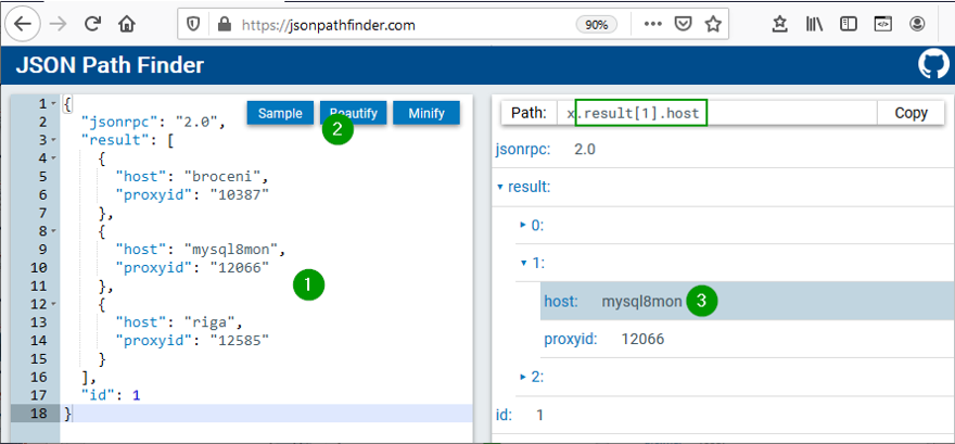
Solution Roadmap: Cross-site Collaboration With the Synology NAS Toolset

Post Syndicated from Janet Lafleur original https://www.backblaze.com/blog/solution-roadmap-cross-site-collaboration-with-the-synology-nas-toolset/

Most teams use their Synology NAS device primarily as a common space to store active data. It’s helpful for collaboration and cuts down on the amount of storage you need to buy for each employee in a media workflow. But if your teams are geographically dispersed, a NAS device at each location will also allow you to sync specific folders across offices and protect the data in them with more reliable and non-duplicative workflows. By setting up an integrated cloud storage tier and using Synology Drive ShareSync, Cloud Sync, and Hyper Backup—all free tools that come with the purchase of your NAS device—you can improve your collaboration capabilities further, and simplify and strengthen data protection for your NAS.

  • Drive ShareSync: Synchronizes folders and files across linked NAS devices.
  • Cloud Sync: Copies files to cloud storage automatically as they’re created or changed.
  • Hyper Backup: Backs up file and systems data to local or cloud storage.

Taken together, these tools, paired with a reasonable and reliable cloud storage, will grow your remote collaboration capacity while better protecting your data. Properly architected, they can make sharing and protecting large files easy, efficient, and secure for internal production, while also making it all look effortless for external clients’ approval and final delivery.

We’ll break out how it all works in the sections below. If you have questions, please reach out in the comments, or contact us.

If you’re more of a visual learner, our Cloud University series also offers an on-demand webinar featuring a demo laboratory showing how to set up cross-office collaboration on a Synology NAS. Otherwise, read on.
In a multi-site file exchange configuration, Synology NAS devices are synced between offices, while cloud storage provides an archive and backup storage target for Synology Cloud Sync and Hyper Backup.

Synchronizing Two or More NAS Devices With Synology Drive ShareSync

Moving media files to a NAS is a great first step towards easier sharing and ensuring that everyone on the team is working on the correct version of any given project. But taking an additional step to also sync folders across multiple NAS devices guarantees that each file is only transferred between sites once, instead of every time a team member accesses the file. This is also a way to reduce network traffic and share large media files that would otherwise require more time and resources.

With Synology Drive ShareSync, you can also choose which specific folders to sync, like folders with corporate brand images or folders for projects which team members across different offices are working on. You also have the option between a one-way and two-way sync, and Synology Drive ShareSync automatically filters out temporary files so that they’re not replicated from primary to secondary.

With Synology Drive ShareSync, specific folders on NAS devices can be synced in a two-way or one-way fashion.

Backing Up and Archiving Media Files With Synology Cloud Sync and Cloud Storage

With Cloud Sync, another tool included with your Synology NAS, you can make a copy of your media files to a cloud storage bucket as soon as they are ingested into the NAS. For creative agencies and corporate video groups that work with high volumes of video and images, syncing data to the cloud on ingest protects the data while it’s active and sets up an easy way to archive it once the project is complete. Here’s how it works:

      1. After a multiple day video or photo shoot, upload the source media files to your Synology NAS. When new media files are found on the NAS, Synology Cloud Sync makes a copy of them to cloud storage.
      2. While the team works on the project, the copies of the media files in the cloud storage bucket serve as a backup in case a file is accidentally deleted or corrupted on the NAS.
      3. Once the team completes the project, you can switch off Synology Cloud Sync for just that folder, then delete the raw footage files from the NAS. This allows you to free up storage space for a new project.
      4. The video and photo files remain in the bucket for the long term, serving as archive copies for future use or when a client returns for another project.
You can configure Synology Cloud Sync to watch folders for new files in specific time periods and control the upload speed to prevent saturating your internet connection.

Using Cloud Sync for Content Review With External Clients

Cloud Sync can also be used to simplify and speed up the editorial review process with clients. Emailing media files like videos and high-res images to external approvers is generally not feasible due to size, and setting up and maintaining FTP servers can be time consuming for you and complicated or confusing for your clients. It’s not an elegant way to put your best creative work in front of them. To simplify the process, create content review folders for each client, generate a link to a ZIP file in a bucket, and share the link with them via email.

Protecting Your NAS Data With Synology Hyper Backup and Backblaze B2

Last, but not least, Synology Hyper Backup can also be configured to do weekly full backups and daily incremental backups of all your NAS data to your cloud storage bucket. Disks can crash and valuable files can be deleted or corrupted, so ensuring you have complete data protection is an essential step in your storage infrastructure.

Hyper Backup will allow you to back up files, folders, and other settings to another destination (like cloud storage) according to a schedule. It also offers flexible retention settings, which allow you to restore an entire shared folder from different points in time. You can learn about how to set it up using this Knowledge Base article.

With Hyper Backup, you gain more control over setting up and managing weekly and daily backups to cloud storage. You can:

  • Encrypt files before transferring them, so that your data will be stored as encrypted files.
  • Choose to only encrypt files during the transfer process.
  • Enable an integrity check to confirm that files were backed up correctly and can be successfully restored.
  • Set integrity checks to run at specific frequencies and times.

Human error is often the inspiration to reach for a backup, but ransomware attacks are on the rise, and a strategy of recycle and rotation practices alongside file encryption helps backups remain unreachable by a ransomware infection. Hyper Backup allows for targeted backup approaches, like saving hourly versions from the previous 24 hours of work, daily versions from the previous month of work, and weekly versions from older than one month. You choose what makes the most sense for your work. You can also set a maximum number of versions if there’s a certain cap you don’t want to exceed. Not only do these smart recycle and rotation practices manage your backups to help protect your organization against ransomware, but they can also reduce storage costs.

Hyper Backup allows you to precisely configure which folders to back up. In this example, raw video footage is excluded because a copy was made by Cloud Sync on upload with the archive-on-ingest strategy.

Set Up Multi-site File Exchange With Synology NAS and Cloud Storage

To learn more about how you can set up your Synology NAS with cloud storage to implement a collaboration and data protection solution like this, one of our solutions engineers recently crafted a guide outlining how to do so with our cloud storage solution.

At the end of the day, collaboration is the soul of much creative work, and orienting your system to make the nuts and bolts of collaboration invisible to the creatives themselves, while ensuring all their content is fully protected, will set your team up for the greatest success. Synology NAS, its impressive built-in software suite, and cloud storage can help you get there.

The post Solution Roadmap: Cross-site Collaboration With the Synology NAS Toolset appeared first on Backblaze Blog | Cloud Storage & Cloud Backup.

Architecture Monthly Magazine: Open Source

Post Syndicated from Annik Stahl original https://aws.amazon.com/blogs/architecture/aws-architecture-monthly-magazine-open-source/

Architecture Monthly Magazine - Open SourceAccording to the Open Source Initiative, the term “open source” was created at a strategy session held in 1998 in Palo Alto, California, shortly after the announcement of the release of the Netscape source code. Stakeholders at that session realized that this announcement created an opportunity to educate and advocate for the superiority of an open development process.

We’ve witnessed big changes in open source in the past 22 years and this year-end issue of Architecture Monthly looks at a few trends, including the shift from businesses only consuming open source to contributing to it. You’ll also going to learn how AWS open source projects are one of the ways we’re making technology less cost-prohibitive and more accessible to everyone.

In this month’s Open Source issue

  • Ask an Expert: Ricardo Sueiras, Principal Advocate for Open Source at AWS
  • Blog: How Amazon Retail Systems Run Machine Learning Predictions with Apache Spark using Deep Java Library
  • Case Study: Absa Transforms IT and Fosters Tech Talent Using AWS
  • Reference Architecture: Running WordPress on AWS
  • Blog: Simplifying Serverless Best Practices with Lambda Powertools
  • Whitepaper: Modernizing the Amazon Database Infrastructure: Migrating from Oracle to AWS
  • Quick Start: Magento on AWS
  • Related Videos: Wix, Viber, UC Santa Cruz, & Redfin

Download the magazine

How to access the magazine

We hope you’re enjoying Architecture Monthly, and we’d like to hear from you—leave us star rating and comment on the Amazon Kindle Newsstand page or contact us anytime at [email protected].

[$] Changed-block tracking and differential backups in QEMU

Post Syndicated from original https://lwn.net/Articles/837053/rss

The block layer of QEMU, the open-source
machine emulator and virtualizer, forms the backbone of many storage
virtualization features
: the QEMU Copy-On-Write (QCOW2) disk-image file format,
disk image chains, point-in-time snapshots, backups, and more. At the
recently concluded 2020 KVM Forum
virtual event, Eric Blake gave a talk
on the current work in QEMU and libvirt
to make differential backups more powerful. As the name implies,
“differential backups” address the efficiency problems of full disk
backups: space usage and speed of backup creation.

Security updates for Tuesday

Post Syndicated from original https://lwn.net/Articles/837538/rss

Security updates have been issued by Debian (libdatetime-timezone-perl, openldap, pacemaker, and restic), Fedora (libmediainfo, mediainfo, mingw-python3, and seamonkey), Gentoo (libexif), openSUSE (raptor), Oracle (kernel and microcode_ctl), Scientific Linux (firefox), SUSE (kernel-firmware, postgresql, postgresql96, postgresql10 and postgresql12, and raptor), and Ubuntu (openldap and postgresql-10, postgresql-12, postgresql-9.5).

Anchoring Trust: A Hardware Secure Boot Story

Post Syndicated from Derek Chamorro original https://blog.cloudflare.com/anchoring-trust-a-hardware-secure-boot-story/

Anchoring Trust: A Hardware Secure Boot Story

Anchoring Trust: A Hardware Secure Boot Story

As a security company, we pride ourselves on finding innovative ways to protect our platform to, in turn, protect the data of our customers. Part of this approach is implementing progressive methods in protecting our hardware at scale. While we have blogged about how we address security threats from application to memory, the attacks on hardware, as well as firmware, have increased substantially. The data cataloged in the National Vulnerability Database (NVD) has shown the frequency of hardware and firmware-level vulnerabilities rising year after year.

Technologies like secure boot, common in desktops and laptops, have been ported over to the server industry as a method to combat firmware-level attacks and protect a device’s boot integrity. These technologies require that you create a trust ‘anchor’, an authoritative entity for which trust is assumed and not derived. A common trust anchor is the system Basic Input/Output System (BIOS) or the Unified Extensible Firmware Interface (UEFI) firmware.

While this ensures that the device boots only signed firmware and operating system bootloaders, does it protect the entire boot process? What protects the BIOS/UEFI firmware from attacks?

The Boot Process

Before we discuss how we secure our boot process, we will first go over how we boot our machines.

Anchoring Trust: A Hardware Secure Boot Story

The above image shows the following sequence of events:

  • After powering on the system (through a baseboard management controller (BMC) or physically pushing a button on the system), the system unconditionally executes the UEFI firmware residing on a flash chip on the motherboard.
  • UEFI performs some hardware and peripheral initialization and executes the Preboot Execution Environment (PXE) code, which is a small program that boots an image over the network and usually resides on a flash chip on the network card.
  • PXE sets up the network card, and downloads and executes a small program bootloader through an open source boot firmware called iPXE.
  • iPXE loads a script that automates a sequence of commands for the bootloader to know how to boot a specific operating system (sometimes several of them). In our case, it loads our Linux kernel, initrd (this contains device drivers which are not directly compiled into the kernel), and a standard Linux root filesystem. After loading these components, the bootloader executes and hands off the control to the kernel.
  • Finally, the Linux kernel loads any additional drivers it needs and starts applications and services.

UEFI Secure Boot

Our UEFI secure boot process is fairly straightforward, albeit customized for our environments. After loading the UEFI firmware from the bootloader, an initialization script defines the following variables:

Platform Key (PK): It serves as the cryptographic root of trust for secure boot, giving capabilities to manipulate and/or validate the other components of the secure boot framework.

Trusted Database (DB): Contains a signed (by platform key) list of hashes of all PCI option ROMs, as well as a public key, which is used to verify the signature of the bootloader and the kernel on boot.

These variables are respectively the master platform public key, which is used to sign all other resources, and an allow list database, containing other certificates, binary file hashes, etc. In default secure boot scenarios, Microsoft keys are used by default. At Cloudflare we use our own, which makes us the root of trust for UEFI:

Anchoring Trust: A Hardware Secure Boot Story

But, by setting our trust anchor in the UEFI firmware, what attack vectors still exist?

UEFI Attacks

As stated previously, firmware and hardware attacks are on the rise. It is clear from the figure below that firmware-related vulnerabilities have increased significantly over the last 10 years, especially since 2017, when the hacker community started attacking the firmware on different platforms:

Anchoring Trust: A Hardware Secure Boot Story

This upward trend, coupled with recent malware findings in UEFI, shows that trusting firmware is becoming increasingly problematic.

By tainting the UEFI firmware image, you poison the entire boot trust chain. The ability to trust firmware integrity is important beyond secure boot. For example, if you can’t trust the firmware not to be compromised, you can’t trust things like trusted platform module (TPM) measurements to be accurate, because the firmware is itself responsible for doing these measurements (e.g a TPM is not an on-path security mechanism, but instead it requires firmware to interact and cooperate with). Firmware may be crafted to extend measurements that are accepted by a remote attestor, but that don’t represent what’s being locally loaded. This could cause firmware to have a questionable measured boot and remote attestation procedure.

Anchoring Trust: A Hardware Secure Boot Story

If we can’t trust firmware, then hardware becomes our last line of defense.

Hardware Root of Trust

Early this year, we made a series of blog posts on why we chose AMD EPYC processors for our Gen X servers. With security in mind, we started turning on features that were available to us and set forth the plan of using AMD silicon as a Hardware Root of Trust (HRoT).

Platform Secure Boot (PSB) is AMD’s implementation of hardware-rooted boot integrity. Why is it better than UEFI firmware-based root of trust? Because it is intended to assert, by a root of trust anchored in the hardware, the integrity and authenticity of the System ROM image before it can execute. It does so by performing the following actions:

  • Authenticates the first block of BIOS/UEFI prior to releasing x86 CPUs from reset.
  • Authenticates the System Read-Only Memory (ROM) contents on each boot, not just during updates.
  • Moves the UEFI Secure Boot trust chain to immutable hardware.

This is accomplished by the AMD Platform Security Processor (PSP), an ARM Cortex-A5 microcontroller that is an immutable part of the system on chip (SoC). The PSB consists of two components:

On-chip Boot ROM

  • Embeds a SHA384 hash of an AMD root signing key
  • Verifies and then loads the off-chip PSP bootloader located in the boot flash

Off-chip Bootloader

  • Locates the PSP directory table that allows the PSP to find and load various images
  • Authenticates first block of BIOS/UEFI code
  • Releases CPUs after successful authentication
Anchoring Trust: A Hardware Secure Boot Story
  1. The PSP secures the On-chip Boot ROM code, loads the off-chip PSP firmware into PSP static random access memory (SRAM) after authenticating the firmware, and passes control to it.
  2. The Off-chip Bootloader (BL) loads and specifies applications in a specific order (whether or not the system goes into a debug state and then a secure EFI application binary interface to the BL)
  3. The system continues initialization through each bootloader stage.
  4. If each stage passes, then the UEFI image is loaded and the x86 cores are released.

Now that we know the booting steps, let’s build an image.

Build Process

Public Key Infrastructure

Before the image gets built, a public key infrastructure (PKI) is created to generate the key pairs involved for signing and validating signatures:

Anchoring Trust: A Hardware Secure Boot Story

Our original device manufacturer (ODM), as a trust extension, creates a key pair (public and private) that is used to sign the first segment of the BIOS (private key) and validates that segment on boot (public key).

On AMD’s side, they have a key pair that is used to sign (the AMD root signing private key) and certify the public key created by the ODM. This is validated by AMD’s root signing public key, which is stored as a hash value (RSASSA-PSS: SHA-384 with 4096-bit key is used as the hashing algorithm for both message and mask generation) in SPI-ROM.

Private keys (both AMD and ODM) are stored in hardware security modules.

Because of the way the PKI mechanisms are built, the system cannot be compromised if only one of the keys is leaked. This is an important piece of the trust hierarchy that is used for image signing.

Certificate Signing Request

Once the PKI infrastructure is established, a BIOS signing key pair is created, together with a certificate signing request (CSR). Creating the CSR uses known common name (CN) fields that many are familiar with:

  • countryName
  • stateOrProvinceName
  • localityName
  • organizationName

In addition to the fields above, the CSR will contain a serialNumber field, a 32-bit integer value represented in ASCII HEX format that encodes the following values:

  • PLATFORM_VENDOR_ID: An 8-bit integer value assigned by AMD for each ODM.
  • PLATFORM_MODEL_ID: A 4-bit integer value assigned to a platform by the ODM.
  • BIOS_KEY_REVISION_ID: is set by the ODM encoding a 4-bit key revision as unary counter value.
  • DISABLE_SECURE_DEBUG: Fuse bit that controls whether secure debug unlock feature is disabled permanently.
  • DISABLE_AMD_BIOS_KEY_USE: Fuse bit that controls if the BIOS, signed by an AMD key, (with vendor ID == 0) is permitted to boot on a CPU with non-zero Vendor ID.
  • DISABLE_BIOS_KEY_ANTI_ROLLBACK: Fuse bit that controls whether BIOS key anti-rollback feature is enabled.
Anchoring Trust: A Hardware Secure Boot Story

Remember these values, as we’ll show how we use them in a bit. Any of the DISABLE values are optional, but recommended based on your security posture/comfort level.

AMD, upon processing the CSR, provides the public part of the BIOS signing key signed and certified by the AMD signing root key as a RSA Public Key Token file (.stkn) format.

Putting It All Together

The following is a step-by-step illustration of how signed UEFI firmware is built:

Anchoring Trust: A Hardware Secure Boot Story
  1. The ODM submits their public key used for signing Cloudflare images to AMD.
  2. AMD signs this key using their RSA private key and passes it back to ODM.
  3. The AMD public key and the signed ODM public key are part of the final BIOS SPI image.
  4. The BIOS source code is compiled and various BIOS components (PEI Volume, Driver eXecution Environment (DXE) volume, NVRAM storage, etc.) are built as usual.
  5. The PSP directory and BIOS directory are built next. PSP directory and BIOS directory table points to the location of various firmware entities.
  6. The ODM builds the signed BIOS Root of Trust Measurement (RTM) signature based on the blob of BIOS PEI volume concatenated with BIOS Directory header, and generates the digital signature of this using the private portion of ODM signing key. The SPI location for signed BIOS RTM code is finally updated with this signature blob.
  7. Finally, the BIOS binaries, PSP directory, BIOS directory and various firmware binaries are combined to build the SPI BIOS image.

Enabling Platform Secure Boot

Platform Secure Boot is enabled at boot time with a PSB-ready firmware image. PSB is configured using a region of one-time programmable (OTP) fuses, specified for the customer. OTP fuses are on-chip non-volatile memory (NVM) that permits data to be written to memory only once. There is NO way to roll the fused CPU back to an unfused one.

Enabling PSB in the field will go through two steps: fusing and validating.

  • Fusing: Fuse the values assigned in the serialNumber field that was generated in the CSR
  • Validating: Validate the fused values and the status code registers

If validation is successful, the BIOS RTM signature is validated using the ODM BIOS signing key, PSB-specific registers (MP0_C2P_MSG_37 and MP0_C2P_MSG_38) are updated with the PSB status and fuse values, and the x86 cores are released

If validation fails, the registers above are updated with the PSB error status and fuse values, and the x86 cores stay in a locked state.

Let’s Boot!

With a signed image in hand, we are ready to enable PSB on a machine. We chose to deploy this on a few machines that had an updated, unsigned AMI UEFI firmware image, in this case version 2.16. We use a couple of different firmware update tools, so, after a quick script, we ran an update to change the firmware version from 2.16 to 2.18C (the signed image):

. $sudo ./UpdateAll.sh
Bin file name is ****.218C

BEGIN

+---------------------------------------------------------------------------+
|                 AMI Firmware Update Utility v5.11.03.1778                 |      
|                 Copyright (C)2018 American Megatrends Inc.                |                       
|                         All Rights Reserved.                              |
+---------------------------------------------------------------------------+
Reading flash ............... done
FFS checksums ......... ok
Check RomLayout ........ ok.
Erasing Boot Block .......... done
Updating Boot Block ......... done
Verifying Boot Block ........ done
Erasing Main Block .......... done
Updating Main Block ......... done
Verifying Main Block ........ done
Erasing NVRAM Block ......... done
Updating NVRAM Block ........ done
Verifying NVRAM Block ....... done
Erasing NCB Block ........... done
Updating NCB Block .......... done
Verifying NCB Block ......... done

Process completed.

After the update completed, we rebooted:

Anchoring Trust: A Hardware Secure Boot Story

After a successful install, we validated that the image was correct via the sysfs information provided in the dmidecode output:

Anchoring Trust: A Hardware Secure Boot Story

Testing

With a signed image installed, we wanted to test that it worked, meaning: what if an unauthorized user installed their own firmware image? We did this by downgrading the image back to an unsigned image, 2.16. In theory, the machine shouldn’t boot as the x86 cores should stay in a locked state. After downgrading, we rebooted and got the following:

Anchoring Trust: A Hardware Secure Boot Story

This isn’t a powered down machine, but the result of booting with an unsigned image.

Anchoring Trust: A Hardware Secure Boot Story

Flashing back to a signed image is done by running the same flashing utility through the BMC, so we weren’t bricked. Nonetheless, the results were successful.

Naming Convention

Our standard UEFI firmware images are alphanumeric, making it difficult to distinguish (by name) the difference between a signed and unsigned image (v2.16A vs v2.18C), for example. There isn’t a remote attestation capability (yet) to probe the PSB status registers or to store these values by means of a signature (e.g. TPM quote). As we transitioned to PSB, we wanted to make this easier to determine by adding a specific suffix: -sig  that we could query in userspace. This would allow us to query this information via Prometheus. Changing the file name alone wouldn’t do it, so we had to make the following changes to reflect a new naming convention for signed images:

  • Update filename
  • Update BIOS version for setup menu
  • Update post message
  • Update SMBIOS type 0 (BIOS version string identifier)

Signed images now have a -sig suffix:

~$ sudo dmidecode -t0
# dmidecode 3.2
Getting SMBIOS data from sysfs.
SMBIOS 3.3.0 present.
# SMBIOS implementations newer than version 3.2.0 are not
# fully supported by this version of dmidecode.

Handle 0x0000, DMI type 0, 26 bytes
BIOS Information
	Vendor: American Megatrends Inc.
	Version: V2.20-sig
	Release Date: 09/29/2020
	Address: 0xF0000
	Runtime Size: 64 kB
	ROM Size: 16 MB

Conclusion

Finding weaknesses in firmware is a challenge that many attackers have taken on. Attacks that physically manipulate the firmware used for performing hardware initialization during the booting process can invalidate many of the common secure boot features that are considered industry standard. By implementing a hardware root of trust that is used for code signing critical boot entities, your hardware becomes a ‘first line of defense’ in ensuring that your server hardware and software integrity can derive trust through cryptographic means.

What’s Next?

While this post discussed our current, AMD-based hardware platform, how will this affect our future hardware generations? One of the benefits of working with diverse vendors like AMD and Ampere (ARM) is that we can ensure they are baking in our desired platform security by default (which we’ll speak about in a future post), making our hardware security outlook that much brighter 😀.

The collective thoughts of the interwebz

By continuing to use the site, you agree to the use of cookies. more information

The cookie settings on this website are set to "allow cookies" to give you the best browsing experience possible. If you continue to use this website without changing your cookie settings or you click "Accept" below then you are consenting to this.

Close