Tag Archives: Amazon Redshift

­­Use fuzzy string matching to approximate duplicate records in Amazon Redshift

Post Syndicated from Sean Beath original https://aws.amazon.com/blogs/big-data/use-fuzzy-string-matching-to-approximate-duplicate-records-in-amazon-redshift/

Amazon Redshift is a fully managed, petabyte-scale data warehouse service in the cloud. Amazon Redshift enables you to run complex SQL analytics at scale and performance on terabytes to petabytes of structured and unstructured data, and make the insights widely available through popular business intelligence (BI) and analytics tools.

It’s common to ingest multiple data sources into Amazon Redshift to perform analytics. Often, each data source will have its own processes of creating and maintaining data, which can lead to data quality challenges within and across sources.

One challenge you may face when performing analytics is the presence of imperfect duplicate records within the source data. Answering questions as simple as “How many unique customers do we have?” can be very challenging when the data you have available is like the following table.

Name Address Date of Birth
Cody Johnson 8 Jeffery Brace, St. Lisatown 1/3/1956
Cody Jonson 8 Jeffery Brace, St. Lisatown 1/3/1956

Although humans can identify that Cody Johnson and Cody Jonson are most likely the same person, it can be difficult to distinguish this using analytics tools. This identification of duplicate records also becomes nearly impossible when working on large datasets across multiple sources.

This post presents one possible approach to addressing this challenge in an Amazon Redshift data warehouse. We import an open-source fuzzy matching Python library to Amazon Redshift, create a simple fuzzy matching user-defined function (UDF), and then create a procedure that weights multiple columns in a table to find matches based on user input. This approach allows you to use the created procedure to approximately identify your unique customers, improving the accuracy of your analytics.

This approach doesn’t solve for data quality issues in source systems, and doesn’t remove the need to have a wholistic data quality strategy. For addressing data quality challenges in Amazon Simple Storage Service (Amazon S3) data lakes and data pipelines, AWS has announced AWS Glue Data Quality (preview). You can also use AWS Glue DataBrew, a visual data preparation tool that makes it easy for data analysts and data scientists to clean and normalize data to prepare it for analytics.

Prerequisites

To complete the steps in this post, you need the following:

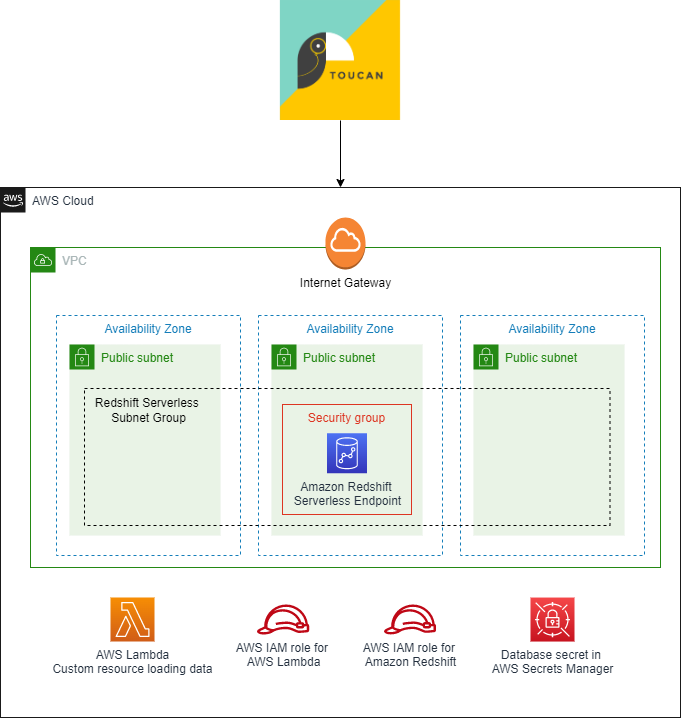
The following AWS CloudFormation stack will deploy a new Redshift Serverless endpoint and an S3 bucket for use in this post.

BDB-2063-launch-cloudformation-stack

All SQL commands shown in this post are available in the following notebook, which can be imported into the Amazon Redshift Query Editor V2.

Overview of the dataset being used

The dataset we use is mimicking a source that holds customer information. This source has a manual process of inserting and updating customer data, and this has led to multiple instances of non-unique customers being represented with duplicate records.

The following examples show some of the data quality issues in the dataset being used.

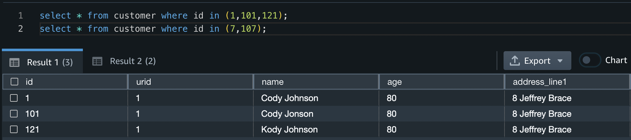
In this first example, all three customers are the same person but have slight differences in the spelling of their names.

id name age address_line1 city postcode state
1 Cody Johnson 80 8 Jeffrey Brace St. Lisatown 2636 South Australia
101 Cody Jonson 80 8 Jeffrey Brace St. Lisatown 2636 South Australia
121 Kody Johnson 80 8 Jeffrey Brace St. Lisatown 2636 South Australia

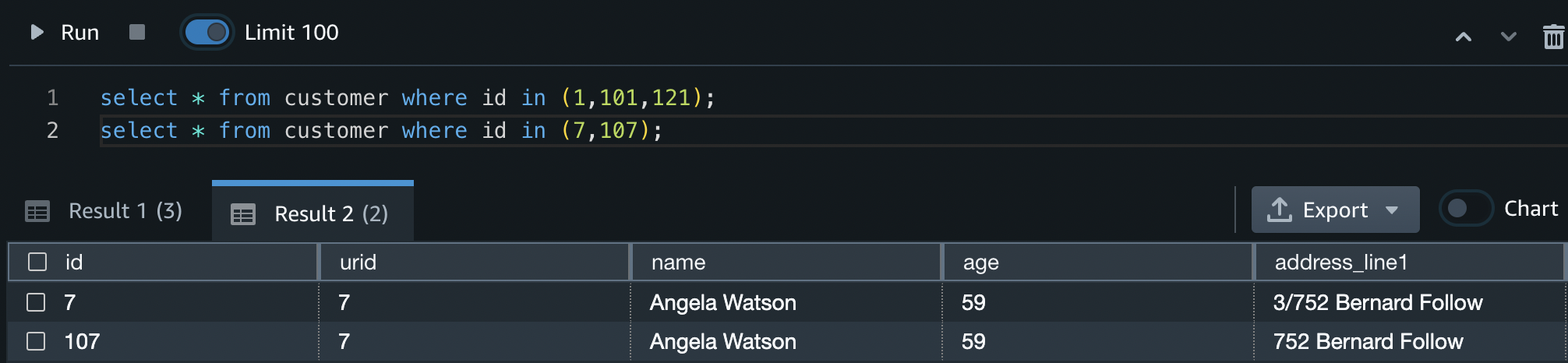
In this next example, the two customers are the same person with slightly different addresses.

id name age address_line1 city postcode state
7 Angela Watson 59 3/752 Bernard Follow Janiceberg 2995 Australian Capital Territory
107 Angela Watson 59 752 Bernard Follow Janiceberg 2995 Australian Capital Territory

In this example, the two customers are different people with the same address. This simulates multiple different customers living at the same address who should still be recognized as different people.

id name age address_line1 city postcode state
6 Michael Hunt 69 8 Santana Rest St. Jessicamouth 2964 Queensland
106 Sarah Hunt 69 8 Santana Rest St. Jessicamouth 2964 Queensland

Load the dataset

First, create a new table in your Redshift Serverless endpoint and copy the test data into it by doing the following:

  1. Open the Query Editor V2 and log in using the admin user name and details defined when the endpoint was created.
  2. Run the following CREATE TABLE statement:
    create table customer (
        id smallint, 
        urid smallint,
        name varchar(100),
        age smallint,
        address_line1 varchar(200),
        city varchar(100),
        postcode smallint,
        state varchar(100)
    )
    ;

    Screenshot of CREATE TABLE statement for customer table being run successfully in Query Editor V2

  3. Run the following COPY command to copy data into the newly created table:
    copy customer (id, name, age, address_line1, city, postcode, state)
    from ' s3://redshift-blogs/fuzzy-string-matching/customer_data.csv'
    IAM_ROLE default
    FORMAT csv
    REGION 'us-east-1'
    IGNOREHEADER 1
    ;

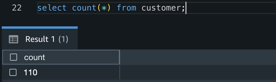
  4. Confirm the COPY succeeded and there are 110 records in the table by running the following query:
    select count(*) from customer;

    Screenshot showing the count of records in the customer table is 110. Query is run in Query Editor V2

Fuzzy matching

Fuzzy string matching, more formally known as approximate string matching, is the technique of finding strings that match a pattern approximately rather than exactly. Commonly (and in this solution), the Levenshtein distance is used to measure the distance between two strings, and therefore their similarity. The smaller the Levenshtein distance between two strings, the more similar they are.

In this solution, we exploit this property of the Levenshtein distance to estimate if two customers are the same person based on multiple attributes of the customer, and it can be expanded to suit many different use cases.

This solution uses TheFuzz, an open-source Python library that implements the Levenshtein distance in a few different ways. We use the partial_ratio function to compare two strings and provide a result between 1–100. If one of the strings matches perfectly with a portion of the other, the partial_ratio function will return 100.

Weighted fuzzy matching

By adding a scaling factor to each of our column fuzzy matches, we can create a weighted fuzzy match for a record. This is especially useful in two scenarios:

  • We have more confidence in some columns of our data than others, and therefore want to prioritize their similarity results.
  • One column is much longer than the others. A single character difference in a long string will have much less impact on the Levenshtein distance than a single character difference in a short string. Therefore, we want to prioritize long string matches over short string matches.

The solution in this post applies weighted fuzzy matching based on user input defined in another table.

Create a table for weight information

This reference table holds two columns; the table name and the column mapping with weights. The column mapping is held in a SUPER datatype, which allows JSON semistructured data to be inserted and queried directly in Amazon Redshift. For examples on how to query semistructured data in Amazon Redshift, refer to Querying semistructured data.

In this example, we apply the largest weight to the column address_line1 (0.5) and the smallest weight to the city and postcode columns (0.1).

Using the Query Editor V2, create a new table in your Redshift Serverless endpoint and insert a record by doing the following:

  1. Run the following CREATE TABLE statement:
    CREATE TABLE ref_unique_record_weight_map(table_name varchar(100), column_mapping SUPER);

  2. Run the following INSERT statement:
    INSERT INTO ref_unique_record_weight_map VALUES (
        'customer',
        JSON_PARSE('{
        "colmap":[
        {
            "colname": "name",
            "colweight": 0.3
        },
        {
            "colname": "address_line1",
            "colweight": 0.5
        },
        {
            "colname": "city",
            "colweight": 0.1
        },
        {
            "colname": "postcode",
            "colweight": 0.1
        }
        ]
    }')
    );

  3. Confirm the mapping data has inserted into the table correctly by running the following query:
    select * from ref_unique_record_weight_map;

    Screenshot showing the result of querying the ref_unique_record_weight_map table in Query Editor V2

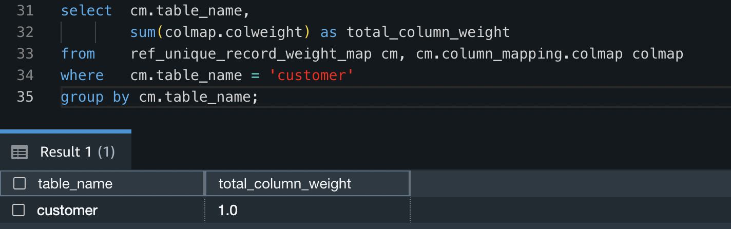
  4. To check all weights for the customer table add up to 1 (100%), run the following query:
    select  cm.table_name, 
            sum(colmap.colweight) as total_column_weight 
    from    ref_unique_record_weight_map cm, cm.column_mapping.colmap colmap 
    where   cm.table_name = 'customer'
    group by cm.table_name;

    Screenshot showing the total weight applied to the customer table is 1.0

User-defined functions

With Amazon Redshift, you can create custom scalar user-defined functions (UDFs) using a Python program. A Python UDF incorporates a Python program that runs when the function is called and returns a single value. In addition to using the standard Python functionality, you can import your own custom Python modules, such as the module described earlier (TheFuzz).

In this solution, we create a Python UDF to take two input values and compare their similarity.

Import external Python libraries to Amazon Redshift

Run the following code snippet to import the TheFuzz module into Amazon Redshift as a new library. This makes the library available within Python UDFs in the Redshift Serverless endpoint. Make sure to provide the name of the S3 bucket you created earlier.

CREATE OR REPLACE LIBRARY thefuzz LANGUAGE plpythonu 
FROM 's3://<your-bucket>/thefuzz.zip' 
IAM_ROLE default;

Create a Python user-defined function

Run the following code snippet to create a new Python UDF called unique_record. This UDF will do the following:

  1. Take two input values that can be of any data type as long as they are the same data type (such as two integers or two varchars).
  2. Import the newly created thefuzz Python library.
  3. Return an integer value comparing the partial ratio between the two input values.
CREATE OR REPLACE FUNCTION unique_record(value_a ANYELEMENT, value_b ANYELEMENT) 
RETURNS INTEGER IMMUTABLE
AS
$$
    from thefuzz import fuzz

    return fuzz.partial_ratio(value_a, value_b)
$$ LANGUAGE plpythonu;

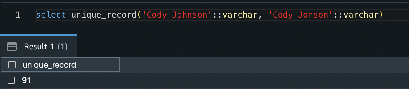
You can test the function by running the following code snippet:

select unique_record('Cody Johnson'::varchar, 'Cody Jonson'::varchar)

The result shows that these two strings are have a similarity value of 91%.

Screenshot showing that using the created function on the Cody Johnson/Cody Jonson name example provides a response of 91

Now that the Python UDF has been created, you can test the response of different input values.

Alternatively, you can follow the amazon-redshift-udfs GitHub repo to install the f_fuzzy_string_match Python UDF.

Stored procedures

Stored procedures are commonly used to encapsulate logic for data transformation, data validation, and business-specific logic. By combining multiple SQL steps into a stored procedure, you can reduce round trips between your applications and the database.

In this solution, we create a stored procedure that applies weighting to multiple columns. Because this logic is common and repeatable regardless of the source table or data, it allows us to create the stored procedure once and use it for multiple purposes.

Create a stored procedure

Run the following code snippet to create a new Amazon Redshift stored procedure called find_unique_id. This procedure will do the following:

  1. Take one input value. This value is the table you would like to create a golden record for (in our case, the customer table).
  2. Declare a set of variables to be used throughout the procedure.
  3. Check to see if weight data is in the staging table created in previous steps.
  4. Build a query string for comparing each column and applying weights using the weight data inserted in previous steps.
  5. For each record in the input table that doesn’t have a unique record ID (URID) yet, it will do the following:
    1. Create a temporary table to stage results. This temporary table will have all potential URIDs from the input table.
    2. Allocate a similarity value to each URID. This value specifies how similar this URID is to the record in question, weighted with the inputs defined.
    3. Choose the closest matched URID, but only if there is a >90% match.
    4. If there is no URID match, create a new URID.
    5. Update the source table with the new URID and move to the next record.

This procedure will only ever look for new URIDs for records that don’t already have one allocated. Therefore, rerunning the URID procedure multiple times will have no impact on the results.

CREATE OR REPLACE PROCEDURE find_unique_id(table_name varchar(100)) AS $$
DECLARE
    unique_record RECORD;
    column_info RECORD;

    column_fuzzy_comparison_string varchar(MAX) := '0.0';
    max_simularity_value decimal(5,2) := 0.0;

    table_check varchar(100);
    temp_column_name varchar(100);
    temp_column_weight decimal(5,2);
    unique_record_id smallint := 0;
BEGIN
    /* 
        Check the ref_unique_record_weight_map table to see if there is a mapping record for the provided table.
        If there is no table, raise an exception
    */
    SELECT INTO table_check cm.table_name from ref_unique_record_weight_map cm where cm.table_name = quote_ident(table_name);
    IF NOT FOUND THEN
        RAISE EXCEPTION 'Input table ''%'' not found in mapping object', table_name;
        RETURN;
    END IF;

    /*
        Build query to be used to compare each column using the mapping record in the ref_unique_record_weight_map table.
        For each column specified in the mapping object, append a weighted comparison of the column
    */
    FOR column_info IN (
        select  colmap.colname::varchar(100) column_name, 
                colmap.colweight column_weight 
        from    ref_unique_record_weight_map cm, cm.column_mapping.colmap colmap 
        where   cm.table_name = quote_ident(table_name)
    ) LOOP
        temp_column_name = column_info.column_name;
        temp_column_weight = column_info.column_weight;
        
        column_fuzzy_comparison_string = column_fuzzy_comparison_string || 
            ' + unique_record(t1.' || 
            temp_column_name || 
            '::varchar, t2.' || 
            temp_column_name || 
            '::varchar)*' || 
            temp_column_weight;
    END LOOP;

    /* Drop temporary table if it exists */
    EXECUTE 'DROP TABLE IF EXISTS #unique_record_table';

    /*
        For each record in the source table that does not have a Unique Record ID (URID):
            1. Create a new temporary table holding all possible URIDs for this record (i.e. all URIDs that have are present). 
                Note: This temporary table will only be present while the simularity check is being calculated
            2. Update each possible URID in the temporary table with it's simularity to the record being checked
            3. Find the most simular record with a URID
                3a. If the most simular record is at least 90% simular, take it's URID (i.e. this is not a unique record, and matches another in the table)
                3b. If there is no record that is 90% simular, create a new URID (i.e. this is a unique record)
            4. Drop the temporary table in preparation for the next record
    */
    FOR unique_record in EXECUTE 'select * from ' || table_name || ' where urid is null order by id asc' LOOP

        RAISE INFO 'test 1';

        /* Create temporary table */
        EXECUTE '
            CREATE TABLE #unique_record_table AS 
            SELECT id, urid, 0.0::decimal(5,2) as simularity_value 
            FROM ' || table_name || '
            where urid is not null
            ';

        /* Update simularity values in temporary table */
        EXECUTE '
            UPDATE #unique_record_table  
            SET simularity_value = round(calc_simularity_value,2)::decimal(5,2)
            FROM (
                SELECT ' || column_fuzzy_comparison_string || ' as calc_simularity_value,
                        t2.id as upd_id
                FROM ' || table_name || ' t1
                INNER JOIN ' || table_name || ' t2
                ON t1.id <> t2.id
                AND t1.id = ' || quote_literal(unique_record.id) || '
                ) t
            WHERE t.upd_id = id
            ';

        /* Find largest simularity value */
        SELECT INTO max_simularity_value simularity_value FROM (
            SELECT  MAX(simularity_value) as simularity_value 
            FROM    #unique_record_table
        );

        /* If there is a >90% similar match, choose it's URID. Otherwise, create a new URID */
        IF max_simularity_value > 90 THEN
            SELECT INTO unique_record_id urid FROM (
                SELECT urid
                FROM #unique_record_table
                WHERE simularity_value = max_simularity_value
            );
        ELSE 
            EXECUTE 'select COALESCE(MAX(urid)+1,1) FROM ' || table_name INTO unique_record_id;
        END IF;
        
        /* Update table with new URID value */
        EXECUTE 'UPDATE ' || table_name || ' SET urid = ' || quote_literal(unique_record_id) || ' WHERE id = ' || quote_literal(unique_record.id);

        /* Drop temporary table and repeat process */
        EXECUTE 'DROP TABLE #unique_record_table';

        max_simularity_value = 0.0;
    END LOOP;

END;
$$ LANGUAGE plpgsql;

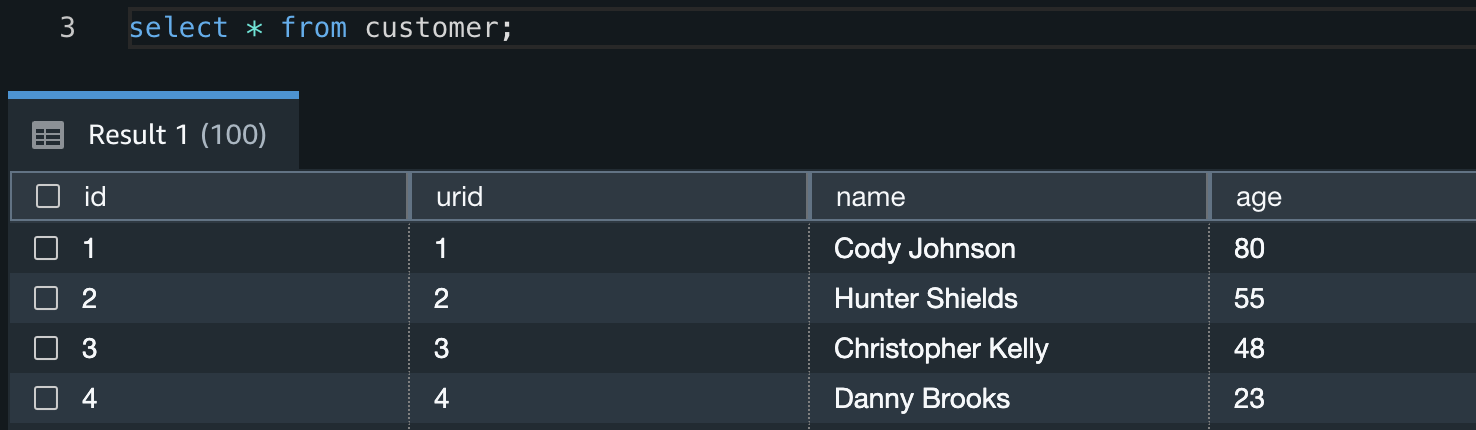
Now that the stored procedure has been created, create the unique record IDs for the customer table by running the following in the Query Editor V2. This will update the urid column of the customer table.

CALL find_unique_id('customer'); 
select * from customer;

Screenshot showing the customer table now has values inserted in the URID column

When the procedure has completed its run, you can identify what duplicate customers were given unique IDs by running the following query:

select * 
from customer
where urid in (
    select urid 
    from customer 
    group by urid 
    having count(*) > 1
    )
order by urid asc
;

Screenshot showing the records that have been identified as duplicate records

From this you can see that IDs 1, 101, and 121 have all been given the same URID, as have IDs 7 and 107.

Screenshot showing the result for IDs 1, 101, and 121

Screenshot showing the result for IDs 7, and 107

The procedure has also correctly identified that IDs 6 and 106 are different customers, and they therefore don’t have the same URID.

Screenshot showing the result for IDs 6, and 106

Clean up

To avoid incurring future reoccurring charges, delete all files in the S3 bucket you created. After you delete the files, go to the AWS CloudFormation console and delete the stack deployed in this post. This will delete all created resources.

Conclusion

In this post, we showed one approach to identifying imperfect duplicate records by applying a fuzzy matching algorithm in Amazon Redshift. This solution allows you to identify data quality issues and apply more accurate analytics to your dataset residing in Amazon Redshift.

We showed how you can use open-source Python libraries to create Python UDFs, and how to create a generic stored procedure to identify imperfect matches. This solution is extendable to provide any functionality required, including adding as a regular process in your ELT (extract, load, and transform) workloads.

Test the created procedure on your datasets to investigate the presence of any imperfect duplicates, and use the knowledge learned throughout this post to create stored procedures and UDFs to implement further functionality.

If you’re new to Amazon Redshift, refer to Getting started with Amazon Redshift for more information and tutorials on Amazon Redshift. You can also refer to the video Get started with Amazon Redshift Serverless for information on starting with Redshift Serverless.


About the Author

Sean Beath is an Analytics Solutions Architect at Amazon Web Services. He has experience in the full delivery lifecycle of data platform modernisation using AWS services and works with customers to help drive analytics value on AWS.

Build a serverless analytics application with Amazon Redshift and Amazon API Gateway

Post Syndicated from David Zhang original https://aws.amazon.com/blogs/big-data/build-a-serverless-analytics-application-with-amazon-redshift-and-amazon-api-gateway/

Serverless applications are a modernized way to perform analytics among business departments and engineering teams. Business teams can gain meaningful insights by simplifying their reporting through web applications and distributing it to a broader audience.

Use cases can include the following:

  • Dashboarding – A webpage consisting of tables and charts where each component can offer insights to a specific business department.
  • Reporting and analysis – An application where you can trigger large analytical queries with dynamic inputs and then view or download the results.
  • Management systems – An application that provides a holistic view of the internal company resources and systems.
  • ETL workflows – A webpage where internal company individuals can trigger specific extract, transform, and load (ETL) workloads in a user-friendly environment with dynamic inputs.
  • Data abstraction – Decouple and refactor underlying data structure and infrastructure.
  • Ease of use – An application where you want to give a large set of user-controlled access to analytics without having to onboard each user to a technical platform. Query updates can be completed in an organized manner and maintenance has minimal overhead.

In this post, you will learn how to build a serverless analytics application using Amazon Redshift Data API and Amazon API Gateway WebSocket and REST APIs.

Amazon Redshift is fully managed by AWS, so you no longer need to worry about data warehouse management tasks such as hardware provisioning, software patching, setup, configuration, monitoring nodes and drives to recover from failures, or backups. The Data API simplifies access to Amazon Redshift because you don’t need to configure drivers and manage database connections. Instead, you can run SQL commands to an Amazon Redshift cluster by simply calling a secured API endpoint provided by the Data API. The Data API takes care of managing database connections and buffering data. The Data API is asynchronous, so you can retrieve your results later.

API Gateway is a fully managed service that makes it easy for developers to publish, maintain, monitor, and secure APIs at any scale. With API Gateway, you can create RESTful APIs and WebSocket APIs that enable real-time two-way communication applications. API Gateway supports containerized and serverless workloads, as well as web applications. API Gateway acts as a reverse proxy to many of the compute resources that AWS offers.

Event-driven model

Event-driven applications are increasingly popular among customers. Analytical reporting web applications can be implemented through an event-driven model. The applications run in response to events such as user actions and unpredictable query events. Decoupling the producer and consumer processes allows greater flexibility in application design and building decoupled processes. This design can be achieved with the Data API and API Gateway WebSocket and REST APIs.

Both REST API calls and WebSocket establish communication between the client and the backend. Due to the popularity of REST, you may wonder why WebSockets are present and how they contribute to an event-driven design.

What are WebSockets and why do we need them?

Unidirectional communication is customary when building analytical web solutions. In traditional environments, the client initiates a REST API call to run a query on the backend and either synchronously or asynchronously waits for the query to complete. The “wait” aspect is engineered to apply the concept of polling. Polling in this context is when the client doesn’t know when a backend process will complete. Therefore, the client will consistently make a request to the backend and check.

What is the problem with polling? Main challenges include the following:

  • Increased traffic in your network bandwidth – A large number of users performing empty checks will impact your backend resources and doesn’t scale well.
  • Cost usage – Empty requests don’t deliver any value to the business. You pay for the unnecessary cost of resources.
  • Delayed response – Polling is scheduled in time intervals. If the query is complete in-between these intervals, the user can only see the results after the next check. This delay impacts the user experience and, in some cases, may result in UI deadlocks.

For more information on polling, check out From Poll to Push: Transform APIs using Amazon API Gateway REST APIs and WebSockets.

WebSockets is another approach compared to REST when establishing communication between the front end and backend. WebSockets enable you to create a full duplex communication channel between the client and the server. In this bidirectional scenario, the client can make a request to the server and is notified when the process is complete. The connection remains open, with minimal network overhead, until the response is received.

You may wonder why REST is present, since you can transfer response data with WebSockets. A WebSocket is a light weight protocol designed for real-time messaging between systems. The protocol is not designed for handling large analytical query data and in API Gateway, each frame’s payload can only hold up to 32 KB. Therefore, the REST API performs large data retrieval.

By using the Data API and API Gateway, you can build decoupled event-driven web applications for your data analytical needs. You can create WebSocket APIs with API Gateway and establish a connection between the client and your backend services. You can then initiate requests to perform analytical queries with the Data API. Due to the Data API’s asynchronous nature, the query completion generates an event to notify the client through the WebSocket channel. The client can decide to either retrieve the query results through a REST API call or perform other follow-up actions. The event-driven architecture enables bidirectional interoperable messages and data while keeping your system components agnostic.

Solution overview

In this post, we show how to create a serverless event-driven web application by querying with the Data API in the backend, establishing a bidirectional communication channel between the user and the backend with the WebSocket feature in API Gateway, and retrieving the results using its REST API feature. Instead of designing an application with long-running API calls, you can use the Data API. The Data API allows you to run SQL queries asynchronously, removing the need to hold long, persistent database connections.

The web application is protected using Amazon Cognito, which is used to authenticate the users before they can utilize the web app and also authorize the REST API calls when made from the application.

Other relevant AWS services in this solution include AWS Lambda and Amazon EventBridge. Lambda is a serverless, event-driven compute resource that enables you to run code without provisioning or managing servers. EventBridge is a serverless event bus allowing you to build event-driven applications.

The solution creates a lightweight WebSocket connection between the browser and the backend. When a user submits a request using WebSockets to the backend, a query is submitted to the Data API. When the query is complete, the Data API sends an event notification to EventBridge. EventBridge signals the system that the data is available and notifies the client. Afterwards, a REST API call is performed to retrieve the query results for the client to view.

We have published this solution on the AWS Samples GitHub repository and will be referencing it during the rest of this post.

The following architecture diagram highlights the end-to-end solution, which you can provision automatically with AWS CloudFormation templates run as part of the shell script with some parameter variables.

The application performs the following steps (note the corresponding numbered steps in the process flow):

  1. A web application is provisioned on AWS Amplify; the user needs to sign up first by providing their email and a password to access the site.
  2. The user verifies their credentials using a pin sent to their email. This step is mandatory for the user to then log in to the application and continue access to the other features of the application.
  3. After the user is signed up and verified, they can sign in to the application and requests data through their web or mobile clients with input parameters. This initiates a WebSocket connection in API Gateway. (Flow 1, 2)
  4. The connection request is handled by a Lambda function, OnConnect, which initiates an asynchronous database query in Amazon Redshift using the Data API. The SQL query is taken from a SQL script in Amazon Simple Storage Service (Amazon S3) with dynamic input from the client. (Flow 3, 4, 6, 7)
  5. In addition, the OnConnect Lambda function stores the connection, statement identifier, and topic name in an Amazon DynamoDB database. The topic name is an extra parameter that can be used if users want to implement multiple reports on the same webpage. This allows the front end to map responses to the correct report. (Flow 3, 4, 5)
  6. The Data API runs the query, mentioned in step 2. When the operation is complete, an event notification is sent to EventBridge. (Flow 8)
  7. EventBridge activates an event rule to redirect that event to another Lambda function, SendMessage. (Flow 9)
  8. The SendMessage function notifies the client that the SQL query is complete via API Gateway. (Flow 10, 11, 12)
  9. After the notification is received, the client performs a REST API call (GET) to fetch the results. (Flow 13, 14, 15, 16)
  10. The GetResult function is triggered, which retrieves the SQL query result and returns it to the client.
  11. The user is now able to view the results on the webpage.
  12. When clients disconnect from their browser, API Gateway automatically deletes the connection information from the DynamoDB table using the onDisconnect function. (Flow 17, 18,19)

Prerequisites

Prior to deploying your event-driven web application, ensure you have the following:

  • An Amazon Redshift cluster in your AWS environment – This is your backend data warehousing solution to run your analytical queries. For instructions to create your Amazon Redshift cluster, refer to Getting started with Amazon Redshift.
  • An S3 bucket that you have access to – The S3 bucket will be your object storage solution where you can store your SQL scripts. To create your S3 bucket, refer to Create your first S3 bucket.

Deploy CloudFormation templates

The code associated to the design is available in the following GitHub repository. You can clone the repository inside an AWS Cloud9 environment in our AWS account. The AWS Cloud9 environment comes with AWS Command Line Interface (AWS CLI) installed, which is used to run the CloudFormation templates to set up the AWS infrastructure. Make sure that the jQuery library is installed; we use it to parse the JSON output during the run of the script.

The complete architecture is set up using three CloudFormation templates:

  • cognito-setup.yaml – Creates the Amazon Cognito user pool to web app client, which is used for authentication and protecting the REST API
  • backend-setup.yaml – Creates all the required Lambda functions and the WebSocket and Rest APIs, and configures them on API Gateway
  • webapp-setup.yaml – Creates the web application hosting using Amplify to connect and communicate with the WebSocket and Rest APIs.

These CloudFormation templates are run using the script.sh shell script, which takes care of all the dependencies as required.

A generic template is provided for you to customize your own DDL SQL scripts as well as your own query SQL scripts. We have created sample scripts for you to follow along.

  1. Download the sample DDL script and upload it to an existing S3 bucket.
  2. Change the IAM role value to your Amazon Redshift cluster’s IAM role with permissions to AmazonS3ReadOnlyAccess.

For this post, we copy the New York Taxi Data 2015 dataset from a public S3 bucket.

  1. Download the sample query script and upload it to an existing S3 bucket.
  2. Upload the modified sample DDL script and the sample query script into a preexisting S3 bucket that you own, and note down the S3 URI path.

If you want to run your own customized version, modify the DDL and query script to fit your scenario.

  1. Edit the script.sh file before you run it and set the values for the following parameters:
    • RedshiftClusterEndpoint (aws_redshift_cluster_ep) – Your Amazon Redshift cluster endpoint available on the AWS Management Console
    • DBUsername (aws_dbuser_name) – Your Amazon Redshift database user name
    • DDBTableName (aws_ddbtable_name) – The name of your DynamoDB table name that will be created
    • WebsocketEndpointSSMParameterName (aws_wsep_param_name) – The parameter name that stores the WebSocket endpoint in AWS Systems Manager Parameter Store.
    • RestApiEndpointSSMParameterName (aws_rapiep_param_name) – The parameter name that stores the REST API endpoint in Parameter Store.
    • DDLScriptS3Path (aws_ddl_script_path) – The S3 URI to the DDL script that you uploaded.
    • QueryScriptS3Path (aws_query_script_path) – The S3 URI to the query script that you uploaded.
    • AWSRegion (aws_region) – The Region where the AWS infrastructure is being set up.
    • CognitoPoolName (aws_user_pool_name) – The name you want to give to your Amazon Cognito user pool
    • ClientAppName (aws_client_app_name) – The name of the client app to be configured for the web app to handle the user authentication for the users

The default acceptable values are already provided as part of the downloaded code.

  1. Run the script using the following command:
./script.sh

During deployment, AWS CloudFormation creates and triggers the Lambda function SetupRedshiftLambdaFunction, which sets up an Amazon Redshift database table and populates data into the table. The following diagram illustrates this process.

Use the demo app

When the shell script is complete, you can start interacting with the demo web app:

  1. On the Amplify console, under All apps in the navigation pane, choose DemoApp.
  2. Choose Run build.

The DemoApp web application goes through a phase of Provision, Build, Deploy.

  1. When it’s complete, use the URL provided to access the web application.

The following screenshot shows the web application page. It has minimal functionality: you can sign in, sign up, or verify a user.

  1. Choose Sign Up.

  1. For Email ID, enter an email.
  2. For Password, enter a password that is at least eight characters long, has at least one uppercase and lowercase letter, at least one number, and at least one special character.
  3. Choose Let’s Enroll.

The Verify your Login to Demo App page opens.

  1. Enter your email and the verification code sent to the email you specified.
  2. Choose Verify.


You’re redirected to a login page.

  1. Sign in using your credentials.

You’re redirected to the demoPage.html website.

  1. Choose Open Connection.

You now have an active WebSocket connection between your browser and your backend AWS environment.

  1. For Trip Month, specify a month (for this example, December) and choose Submit.

You have now defined the month and year you want to query your data upon. After a few seconds, you can to see the output delivered from the WebSocket.

You may continue using the active WebSocket connection for additional queries—just choose a different month and choose Submit again.

  1. When you’re done, choose Close Connection to close the WebSocket connection.

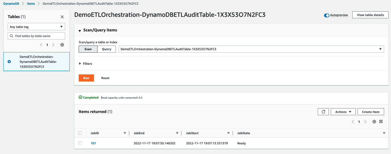
For exploratory purposes, while your WebSocket connection is active, you can navigate to your DynamoDB table on the DynamoDB console to view the items that are currently stored. After the WebSocket connection is closed, the items stored in DynamoDB are deleted.

Clean up

To clean up your resources, complete the following steps:

  1. On the Amazon S3 console, navigate to the S3 bucket containing the sample DDL script and query script and delete them from the bucket.
  2. On the Amazon Redshift console, navigate to your Amazon Redshift cluster and delete the data you copied over from the sample DDL script.
    1. Run truncate nyc_yellow_taxi;
    2. Run drop table nyc_yellow_taxi;
  3. On the AWS CloudFormation console, navigate to the CloudFormation stacks and choose Delete. Delete the stacks in the following order:
    1. WebappSetup
    2. BackendSetup
    3. CognitoSetup

All resources created in this solution will be deleted.

Monitoring

You can monitor your event-driven web application events, user activity, and API usage with Amazon CloudWatch and AWS CloudTrail. Most areas of this solution already have logging enabled. To view your API Gateway logs, you can turn on CloudWatch Logs. Lambda comes with default logging and monitoring and can be accessed with CloudWatch.

Security

You can secure access to the application using Amazon Cognito, which is a developer-centric and cost-effective customer authentication, authorization, and user management solution. It provides both identity store and federation options that can scale easily. Amazon Cognito supports logins with social identity providers and SAML or OIDC-based identity providers, and supports various compliance standards. It operates on open identity standards (OAuth2.0, SAML 2.0, and OpenID Connect). You can also integrate it with API Gateway to authenticate and authorize the REST API calls either using the Amazon Cognito client app or a Lambda function.

Considerations

The nature of this application includes a front-end client initializing SQL queries to Amazon Redshift. An important component to consider are potential malicious activities that the client can perform, such as SQL injections. With the current implementation, that is not possible. In this solution, the SQL queries preexist in your AWS environment and are DQL statements (they don’t alter the data or structure). However, as you develop this application to fit your business, you should evaluate these areas of risk.

AWS offers a variety of security services to help you secure your workloads and applications in the cloud, including AWS Shield, AWS Network Firewall, AWS Web Application Firewall, and more. For more information and a full list, refer to Security, Identity, and Compliance on AWS.

Cost optimization

The AWS services that the CloudFormation templates provision in this solution are all serverless. In terms of cost optimization, you only pay for what you use. This model also allows you to scale without manual intervention. Review the following pages to determine the associated pricing for each service:

Conclusion

In this post, we showed you how to create an event-driven application using the Amazon Redshift Data API and API Gateway WebSocket and REST APIs. The solution helps you build data analytical web applications in an event-driven architecture, decouple your application, optimize long-running database queries processes, and avoid unnecessary polling requests between the client and the backend.

You also used severless technologies, API Gateway, Lambda, DynamoDB, and EventBridge. You didn’t have to manage or provision any servers throughout this process.

This event-driven, serverless architecture offers greater extensibility and simplicity, making it easier to maintain and release new features. Adding new components or third-party products is also simplified.

With the instructions in this post and the generic CloudFormation templates we provided, you can customize your own event-driven application tailored to your business. For feedback or contributions, we welcome you to contact us through the AWS Samples GitHub Repository by creating an issue.


About the Authors

David Zhang is an AWS Data Architect in Global Financial Services. He specializes in designing and implementing serverless analytics infrastructure, data management, ETL, and big data systems. He helps customers modernize their data platforms on AWS. David is also an active speaker and contributor to AWS conferences, technical content, and open-source initiatives. During his free time, he enjoys playing volleyball, tennis, and weightlifting. Feel free to connect with him on LinkedIn.

Manash Deb is a Software Development Manager in the AWS Directory Service team. With over 18 years of software dev experience, his passion is designing and delivering highly scalable, secure, zero-maintenance applications in the AWS identity and data analytics space. He loves mentoring and coaching others and to act as a catalyst and force multiplier, leading highly motivated engineering teams, and building large-scale distributed systems.

Pavan Kumar Vadupu Lakshman Manikya is an AWS Solutions Architect who helps customers design robust, scalable solutions across multiple industries. With a background in enterprise architecture and software development, Pavan has contributed in creating solutions to handle API security, API management, microservices, and geospatial information system use cases for his customers. He is passionate about learning new technologies and solving, automating, and simplifying customer problems using these solutions.

What’s new in Amazon Redshift – 2022, a year in review

Post Syndicated from Manan Goel original https://aws.amazon.com/blogs/big-data/whats-new-in-amazon-redshift-2022-a-year-in-review/

In 2021 and 2020, we told you about the new features in Amazon Redshift that make it easier, faster, and more cost-effective to analyze all your data and find rich and powerful insights. In 2022, we are happy to report that the Amazon Redshift team was hard at work. We worked backward from customer requirements and announced multiple new features to make it easier, faster, and more cost-effective to analyze all your data. This post covers some of these new features.

At AWS, for data and analytics, our strategy is to give you a modern data architecture that helps you break free from data silos; have purpose-built data, analytics, machine learning (ML), and artificial intelligence services to use the right tool for the right job; and have open, governed, secure, and fully managed services to make analytics available to everyone. Within AWS’s modern data architecture, Amazon Redshift as the cloud data warehouse remains a key component, enabling you to run complex SQL analytics at scale and performance on terabytes to petabytes of structured and unstructured data, and make the insights widely available through popular business intelligence (BI) and analytics tools. We continue to work backward from customers’ requirements, and in 2022 launched over 40 features in Amazon Redshift to help customers with their top data warehousing use cases, including:

  • Self-service analytics
  • Easy data ingestion
  • Data sharing and collaboration
  • Data science and machine learning
  • Secure and reliable analytics
  • Best price performance analytics

Let’s dive deeper and discuss the new Amazon Redshift features in these areas.

Self-service analytics

Customers continue to tell us that data and analytics is becoming ubiquitous, and everyone in their organization needs analytics. We announced Amazon Redshift Serverless (in preview) in 2021 to make it easy to run and scale analytics in seconds without having to provision and manage data warehouse infrastructure. In July 2022, we announced the general availability of Redshift Serverless, and since then thousands of customers, including Peloton, Broadridge Financials, and NextGen Healthcare, have used it to quickly and easily analyze their data. Amazon Redshift Serverless automatically provisions and intelligently scales data warehouse capacity to deliver high performance for all your analytics, and you only pay for the compute used for the duration of the workloads on a per-second basis. Since GA, we have added features like resource tagging, simplified monitoring, and availability in additional AWS Regions to further simplify billing and expand the reach across more Regions worldwide.

In 2021, we launched Amazon Redshift Query Editor V2, which is a free web-based tool for data analysts, data scientists, and developers to explore, analyze, and collaborate on data in Amazon Redshift data warehouses and data lakes. In 2022, Query Editor V2 got additional enhancements such as notebook support for improved collaboration to author, organize, and annotate queries; user access through identity provider (IdP) credentials for single sign-on; and the ability to run multiple queries concurrently to improve developer productivity.

Autonomics is another area where we are actively working to use ML-based optimizations and give customers a self-learning and self-optimizing data warehouse. In 2022, we announced the general availability of Automated Materialized Views (AutoMVs) to improve the performance of queries (reduce the total runtime) without any user effort by automatically creating and maintaining materialized views. AutoMVs, combined with automatic refresh, incremental refresh, and automatic query rewriting for materialized views, made materialized views maintenance free, giving you faster performance automatically. In addition, the automatic table optimization (ATO) capability for schema optimization and automatic workload management (auto WLM) capability for workload optimization got further improvements for better query performance.

Easy data ingestion

Customers tell us that they have their data distributed over multiple data sources like transactional databases, data warehouses, data lakes, and big data systems. They want the flexibility to integrate this data with no-code/low-code, zero-ETL data pipelines or analyze this data in place without moving it. Customers tell us that their current data pipelines are complex, manual, rigid, and slow, resulting in incomplete, inconsistent, and stale views of data, limiting insights. Customers have asked us for a better way forward, and we are pleased to announce a number of new capabilities to simplify and automate data pipelines.

Amazon Aurora zero-ETL integration with Amazon Redshift (preview) enables you to run near-real-time analytics and ML on petabytes of transactional data. It offers a no-code solution for making transactional data from multiple Amazon Aurora databases available in Amazon Redshift data warehouses within seconds of being written to Aurora, eliminating the need to build and maintain complex data pipelines. With this feature, Aurora customers can also access Amazon Redshift capabilities such as complex SQL analytics, built-in ML, data sharing, and federated access to multiple data stores and data lakes. This feature is now available in preview for Amazon Aurora MySQL-Compatible Edition version 3 (with MySQL 8.0 compatibility), and you can request access to the preview.

Amazon Redshift now supports auto-copy from Amazon S3 (preview) to simplify data loading from Amazon Simple Storage Service (Amazon S3) into Amazon Redshift. You can now set up continuous file ingestion rules (copy jobs) to track your Amazon S3 paths and automatically load new files without the need for additional tools or custom solutions. Copy jobs can be monitored through system tables, and they automatically keep track of previously loaded files and exclude them from the ingestion process to prevent data duplication. This feature is now available in preview; you can try this feature by creating a new cluster using the preview track.

Customers continue to tell us that they need instantaneous, in-the-moment, real-time analytics, and we are pleased to announce the general availability of streaming ingestion support in Amazon Redshift for Amazon Kinesis Data Streams and Amazon Managed Streaming for Apache Kafka (Amazon MSK). This feature eliminates the need to stage streaming data in Amazon S3 before ingesting it into Amazon Redshift, enabling you to achieve low latency, measured in seconds, while ingesting hundreds of megabytes of streaming data per second into your data warehouses. You can use SQL within Amazon Redshift to connect to and directly ingest data from multiple Kinesis data streams or MSK topics, create auto-refreshing streaming materialized views with transformations on top of streams directly to access streaming data, and combine real-time data with historical data for better insights. For example, Adobe has integrated Amazon Redshift streaming ingestion as part of their Adobe Experience Platform for ingesting and analyzing, in real time, the web and applications clickstream and session data for various applications like CRM and customer support applications.

Customers have told us that they want simple, out-of-the-box integration between Amazon Redshift, BI and ETL (extract, transform, and load) tools, and business applications like Salesforce and Marketo. We are pleased to announce the general availability of Informatica Data Loader for Amazon Redshift, which enables you to use Informatica Data Loader for high-speed and high-volume data loading into Amazon Redshift for free. You can simply select the Informatica Data Loader option on the Amazon Redshift console. Once in Informatica Data Loader, you can connect to sources such as Salesforce or Marketo, choose Amazon Redshift as a target, and begin to load your data.

Data sharing and collaboration

Customers continue to tell us that they want to analyze all their first-party and third-party data and make the rich data-driven insights available to their customers, partners, and suppliers. We launched new features in 2021, such as Data Sharing and AWS Data Exchange integration, to make it easier for you to analyze all of your data and share it within and outside your organizations.

A great example of a customer using data sharing is Orion. Orion provides real-time data as a service (DaaS) solutions for customers in the financial services industry, such as wealth management, asset management, and investment management providers. They have over 2,500 data sources that are primarily SQL Server databases sitting both on premises and in AWS. Data is streamed using Kafka connecters into Amazon Redshift. They have a producer cluster that receives all this data and then uses Data Sharing to share data in real time for collaboration. This is a multi-tenant architecture that serves multiple clients. Given the sensitivity of their data, data sharing is a way to provide workload isolation between clusters and also securely share that data to end-users.

In 2022, we continued to invest in this area to improve the performance, governance, and developer productivity with new features to make it easier, simpler, and faster to share and collaborate on data.

As customers are building large-scale data sharing configurations, they have asked for simplified governance and security for shared data, and we are adding centralized access control with AWS Lake Formation for Amazon Redshift datashares to enable sharing live data across multiple Amazon Redshift data warehouses. With this feature, Amazon Redshift now supports simplified governance of Amazon Redshift datashares by using AWS Lake Formation as a single pane of glass to centrally manage data or permissions on datashares. You can view, modify, and audit permissions, including row-level and column-level security on the tables and views in the Amazon Redshift datashares, using Lake Formation APIs and the AWS Management Console, and allow the Amazon Redshift datashares to be discovered and consumed by other Amazon Redshift data warehouses.

Data science and machine learning

Customers continue to tell us that they want their data and analytics systems to help them answer a wide range of questions, from what is happening in their business (descriptive analytics) to why is it happening (diagnostic analytics) and what will happen in the future (predictive analytics). Amazon Redshift provides features like complex SQL analytics, data lake analytics, and Amazon Redshift ML for customers to analyze their data and discover powerful insights. Redshift ML integrates Amazon Redshift with Amazon SageMaker, a fully managed ML service, enabling you to create, train, and deploy ML models using familiar SQL commands.

Customers have also asked us for better integration between Amazon Redshift and Apache Spark, so we are excited to announce Amazon Redshift integration for Apache Spark to make data warehouses easily accessible for Spark-based applications. Now, developers using AWS analytics and ML services such as Amazon EMR, AWS Glue, and SageMaker can effortlessly build Apache Spark applications that read from and write to their Amazon Redshift data warehouses. Amazon EMR and AWS Glue package the Redshift-Spark connector so you can easily connect to your data warehouse from your Spark-based applications. You can use several pushdown capabilities for operations such as sort, aggregate, limit, join, and scalar functions so that only the relevant data is moved from your Amazon Redshift data warehouse to the consuming Spark application. You can also make your applications more secure by utilizing AWS Identity and Access Management (IAM) credentials to connect to Amazon Redshift.

Secure and reliable analytics

Customers continue to tell us that their data warehouses are mission-critical systems that need high availability, reliability, and security. We launched a number of new features in 2022 in this area.

Amazon Redshift now supports Multi-AZ deployments (in preview) for RA3 instance-based clusters, which enables running your data warehouse in multiple AWS Availability Zones simultaneously and continuous operation in unforeseen Availability Zone-wide failure scenarios. Multi-AZ support is already available for Redshift Serverless. An Amazon Redshift Multi-AZ deployment allows you to recover in case of Availability Zone failures without any user intervention. An Amazon Redshift Multi-AZ data warehouse is accessed as a single data warehouse with one endpoint, and helps you maximize performance by distributing workload processing across multiple Availability Zones automatically. No application changes are needed to maintain business continuity during unforeseen outages.

In 2022, we launched features like role-based access control, row-level security, and data masking (in preview) to make it easier for you to manage access and decide who has access to which data, including obfuscating personally identifiable information (PII) like credit card numbers.

You can use role-based access control (RBAC) to control end-user access to data at a broad or granular level based on an end-user’s job role and permissions. With RBAC, you can create a role using SQL, grant a collection of granular permissions to the role, and then assign that role to end-users. Roles can be granted object-level, column-level, and system-level permissions. Additionally, RBAC introduces out-of-box system roles for DBAs, operators, security admins, or customized roles.

Row-level security (RLS) simplifies design and implementation of fine-grained access to the rows in tables. With RLS, you can restrict access to a subset of rows within a table based on the users’ job role or permissions with SQL.

Amazon Redshift support for dynamic data masking (DDM), which is now available in preview, allows you to simplify protecting PII such as Social Security numbers, credits card numbers, and phone numbers in your Amazon Redshift data warehouse. With dynamic data masking, you control access to your data through simple SQL-based masking policies that determine how Amazon Redshift returns sensitive data to the user at query time. You can create masking policies to define consistent, format-preserving, and irreversible masked data values. You can apply a masking policy on a specific column or list of columns in a table. Also, you have the flexibility of choosing how to show the masked data. For example, you can completely hide the data, replace partial real values with wildcard characters, or define your own way to mask the data using SQL expressions, Python, or AWS Lambda user-defined functions. Additionally, you can apply a conditional masking policy based on other columns, which selectively protects the column data in a table based on the values in one or more different columns.

We also announced enhancements to audit logging, native integration with Microsoft Azure Active Directory, and support for default IAM roles in additional Regions to further simplify security management.

Best price performance analytics

Customers continue to tell us that they need fast and cost-effective data warehouses that deliver high performance at any scale while keeping costs low. From day 1 since Amazon Redshift’s launch in 2012, we have taken a data-driven approach and used fleet telemetry to build a cloud data warehouse service that gives you the best price performance at any scale. Over the years, we have evolved Amazon Redshift’s architecture and launched features such as Redshift Managed Storage (RMS) for separation of storage and compute, Amazon Redshift Spectrum for data lake queries, automatic table optimization for physical schema optimization, automatic workload management to prioritize workloads and allocate the right compute and memory, cluster resize to scale compute and storage vertically, and concurrency scaling to dynamically scale compute out or in. Our performance benchmarks continue to demonstrate Amazon Redshift’s price performance leadership.

In 2022, we added new features such as the general availability of concurrency scaling for write operations like COPY, INSERT, UPDATE, and DELETE to support virtually unlimited concurrent users and queries. We also introduced performance improvements for string-based data processing through vectorized scans over lightweight, CPU-efficient, dictionary-encoded string columns, which allows the database engine to operate directly over compressed data.

We also added support for SQL operators such as MERGE (single operator for inserts or updates); CONNECY_BY (for hierarchical queries); GROUPING SETS, ROLLUP, and CUBE (for multi-dimensional reporting); and increased the size of the SUPER data type to 16 MB to make it easier for you to migrate from legacy data warehouses to Amazon Redshift.

Conclusion

Our customers continue to tell us that data and analytics remains a top priority for them and the need to cost-effectively extract more business value from their data during these times is more pronounced than any other time in the past. Amazon Redshift as your cloud data warehouse enables you to run complex SQL analytics with scale and performance on terabytes to petabytes of structured and unstructured data and make the insights widely available through popular BI and analytics tools.

Although we launched over 40 features in 2022 and the pace of innovation continues to accelerate, it remains day 1 and we look forward to hearing from you on how these features help you unlock more value for your organizations. We invite you to try these new features and get in touch with us through your AWS account team if you have further comments.


About the author

Manan Goel is a Product Go-To-Market Leader for AWS Analytics Services including Amazon Redshift at AWS. He has more than 25 years of experience and is well versed with databases, data warehousing, business intelligence, and analytics. Manan holds a MBA from Duke University and a BS in Electronics & Communications engineering.

Build near real-time logistics dashboards using Amazon Redshift and Amazon Managed Grafana for better operational intelligence

Post Syndicated from Paul Villena original https://aws.amazon.com/blogs/big-data/build-near-real-time-logistics-dashboards-using-amazon-redshift-and-amazon-managed-grafana-for-better-operational-intelligence/

Amazon Redshift is a fully managed data warehousing service that is currently helping tens of thousands of customers manage analytics at scale. It continues to lead price-performance benchmarks, and separates compute and storage so each can be scaled independently and you only pay for what you need. It also eliminates data silos by simplifying access to your operational databases, data warehouse, and data lake with consistent security and governance policies.

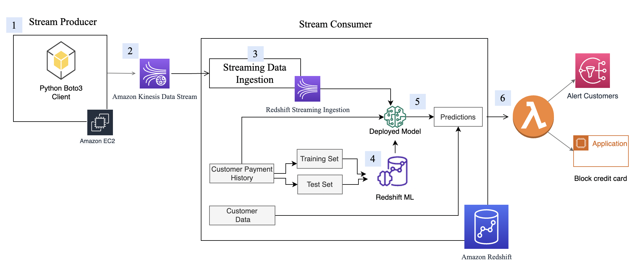
With the Amazon Redshift streaming ingestion feature, it’s easier than ever to access and analyze data coming from real-time data sources. It simplifies the streaming architecture by providing native integration between Amazon Redshift and the streaming engines in AWS, which are Amazon Kinesis Data Streams and Amazon Managed Streaming for Apache Kafka (Amazon MSK). Streaming data sources like system logs, social media feeds, and IoT streams can continue to push events to the streaming engines, and Amazon Redshift simply becomes just another consumer. Before Amazon Redshift streaming was available, we had to stage the streaming data first in Amazon Simple Storage Service (Amazon S3) and then run the copy command to load it into Amazon Redshift. Eliminating the need to stage data in Amazon S3 results in faster performance and improved latency. With this feature, we can ingest hundreds of megabytes of data per second and have a latency of just a few seconds.

Another common challenge for our customers is the additional skill required when using streaming data. In Amazon Redshift streaming ingestion, only SQL is required. We use SQL to do the following:

  • Define the integration between Amazon Redshift and our streaming engines with the creation of external schema
  • Create the different streaming database objects that are actually materialized views
  • Query and analyze the streaming data
  • Generate new features that are used to predict delays using machine learning (ML)
  • Perform inferencing natively using Amazon Redshift ML

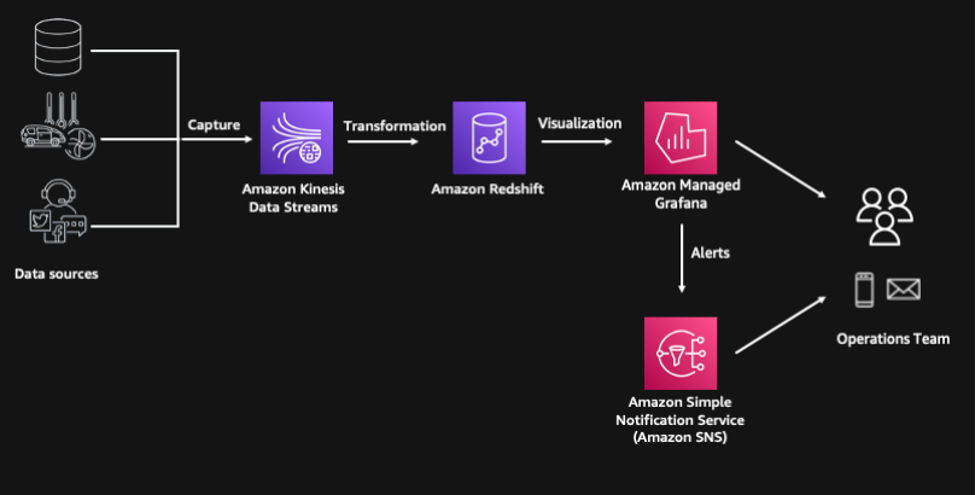
In this post, we build a near real-time logistics dashboard using Amazon Redshift and Amazon Managed Grafana. Our example is an operational intelligence dashboard for a logistics company that provides situational awareness and augmented intelligence for their operations team. From this dashboard, the team can see the current state of their consignments and their logistics fleet based on events that happened only a few seconds ago. It also shows the consignment delay predictions of an Amazon Redshift ML model that helps them proactively respond to disruptions before they even happen.

Solution overview

This solution is composed of the following components, and the provisioning of resources is automated using the AWS Cloud Development Kit (AWS CDK):

  • Multiple streaming data sources are simulated through Python code running in our serverless compute service, AWS Lambda
  • The streaming events are captured by Amazon Kinesis Data Streams, which is a highly scalable serverless streaming data service
  • We use the Amazon Redshift streaming ingestion feature to process and store the streaming data and Amazon Redshift ML to predict the likelihood of a consignment getting delayed
  • We use AWS Step Functions for serverless workflow orchestration
  • The solution includes a consumption layer built on Amazon Managed Grafana where we can visualize the insights and even generate alerts through Amazon Simple Notification Service (Amazon SNS) for our operations team

The following diagram illustrates our solution architecture.

Prerequisites

The project has the following prerequisites:

Sample deployment using the AWS CDK

The AWS CDK is an open-source project that allows you to define your cloud infrastructure using familiar programming languages. It uses high-level constructs to represent AWS components to simplify the build process. In this post, we use Python to define the cloud infrastructure due to its familiarity to many data and analytics professionals.

Clone the GitHub repository and install the Python dependencies:

git clone https://github.com/aws-samples/amazon-redshift-streaming-workshop
cd amazon-redshift-streaming-workshop
python3 -m venv .venv
source .venv/bin/activate
pip install -r requirements.txt

Next, bootstrap the AWS CDK. This sets up the resources required by the AWS CDK to deploy into the AWS account. This step is only required if you haven’t used the AWS CDK in the deployment account and Region.

cdk bootstrap

Deploy all stacks:

cdk deploy IngestionStack 
cdk deploy RedshiftStack 
cdk deploy StepFunctionStack

The entire deployment time takes 10–15 minutes.

Access streaming data using Amazon Redshift streaming ingestion

The AWS CDK deployment provisions an Amazon Redshift cluster with the appropriate default IAM role to access the Kinesis data stream. We can create an external schema to establish a connection between the Amazon Redshift cluster and the Kinesis data stream:

CREATE EXTERNAL SCHEMA ext_kinesis FROM KINESIS
IAM_ROLE default;

For instructions on how to connect to the cluster, refer to Connecting to the Redshift Cluster.

We use a materialized view to parse data in the Kinesis data stream. In this case, the whole payload is ingested as is and stored using the SUPER data type in Amazon Redshift. Data stored in streaming engines is usually in semi-structured format, and the SUPER data type provides a fast and efficient way to analyze semi-structured data within Amazon Redshift.


See the following code:

CREATE MATERIALIZED VIEW consignment_stream AS
SELECT approximate_arrival_timestamp,
JSON_PARSE(from_varbyte(kinesis_data, 'utf-8')) as consignment_data FROM ext_kinesis.consignment_stream
WHERE is_utf8(kinesis_data)
AND is_valid_json(from_varbyte(kinesis_data, 'utf-8'));

Refreshing the materialized view invokes Amazon Redshift to read data directly from the Kinesis data stream and load it into the materialized view. This refresh can be done automatically by adding the AUTO REFRESH clause in the materialized view definition. However, in this example, we are orchestrating the end-to-end data pipeline using AWS Step Functions.

REFRESH MATERIALIZED VIEW consignment_stream;

Now we can start running queries against our streaming data and unify it with other datasets like logistics fleet data. If we want to know the distribution of our consignments across different states, we can easily unpack the contents of the JSON payload using the PartiQL syntax.

SELECT cs.consignment_data.origin_state::VARCHAR,
COUNT(1) number_of_consignments,
AVG(on_the_move) running_fleet,
AVG(scheduled_maintenance + unscheduled_maintenance) under_maintenance
FROM consignment_stream cs
INNER JOIN fleet_summary fs
on TRIM(cs.consignment_data.origin_state::VARCHAR) = fs.vehicle_location
GROUP BY 1

Generate features using Amazon Redshift SQL functions

The next step is to transform and enrich the streaming data using Amazon Redshift SQL to generate additional features that will be used by Amazon Redshift ML for its predictions. We use date and time functions to identify the day of the week, and calculate the number of days between the order date and target delivery date.

We also use geospatial functions, specifically ST_DistanceSphere, to calculate the distance between origin and destination locations. The GEOMETRY data type within Amazon Redshift provides a cost-effective way to analyze geospatial data such as longitude and latitudes at scale. In this example, the addresses have already been converted to longitude and latitude. However, if you need to perform geocoding, you can integrate Amazon Location Services with Amazon Redshift using user-defined functions (UDFs). On top of geocoding, Amazon Location Service also allows you to more accurately calculate route distance between origin and destination, and even specify waypoints along the way.

We use another materialized view to persist these transformations. A materialized view provides a simple yet efficient way to create data pipelines using its incremental refresh capability. Amazon Redshift identifies the incremental changes from the last refresh and only updates the target materialized view based on these changes. In this materialized view, all our transformations are deterministic, so we expect our data to be consistent when going through a full refresh or an incremental refresh.


See the following code:

CREATE MATERIALIZED VIEW consignment_transformed AS
SELECT
consignment_data.consignmentid::INT consignment_id,
consignment_data.consignment_date::TIMESTAMP consignment_date,
consignment_data.delivery_date::TIMESTAMP delivery_date,
consignment_data.origin_state::VARCHAR origin_state,
consignment_data.destination_state::VARCHAR destination_state,
consignment_data.revenue::FLOAT revenue,
consignment_data.cost::FLOAT cost,
DATE_PART(dayofweek, consignment_data.consignment_date::TIMESTAMP)::INT day_of_week,
DATE_PART(hour, consignment_data.consignment_date::TIMESTAMP)::INT "hour",
DATEDIFF(days,
consignment_data.consignment_date::TIMESTAMP,
consignment_data.delivery_date::TIMESTAMP
)::INT days_to_deliver,
(ST_DistanceSphere(
ST_Point(consignment_data.origin_lat::FLOAT, consignment_data.origin_long::FLOAT),
ST_Point(consignment_data.destination_lat::FLOAT, consignment_data.destination_long::FLOAT)
) / 1000 --convert to km
) delivery_distance
FROM consignment_stream;

Predict delays using Amazon Redshift ML

We can use this enriched data to make predictions on the delay probability of a consignment. Amazon Redshift ML is a feature of Amazon Redshift that allows you to use the power of Amazon Redshift to build, train, and deploy ML models directly within your data warehouse.

The training of a new Amazon Redshift ML model has been initiated as part of the AWS CDK deployment using the CREATE MODEL statement. The training dataset is defined in the FROM clause, and TARGET defines which column the model is trying to predict. The FUNCTION clause defines the name of the function that is used to make predictions.

CREATE MODEL ml_delay_prediction -- already executed by CDK
FROM (SELECT * FROM ext_s3.consignment_train)
TARGET probability
FUNCTION fnc_delay_probabilty
IAM_ROLE default
SETTINGS (
MAX_RUNTIME 1800, --seconds
S3_BUCKET '<ingestionstack-s3bucketname>' --replace S3 bucket name
)

This simplified model is trained using historical observations, and the training process takes around 30 minutes to complete. You can check the status of the training job by running the SHOW MODEL statement:

SHOW MODEL ml_delay_prediction;

When the model is ready, we can start making predictions on new data that is streamed into Amazon Redshift. Predictions are generated using the Amazon Redshift ML function that was defined during the training process. We pass the calculated features from the transformed materialized view into this function, and the prediction results populate the delay_probability column.

This final output is persisted into the consignment_predictions table, and Step Functions is orchestrating the ongoing incremental data load into this target table. We use a table for the final output, instead of a materialized view, because ML predictions have randomness involved and it may give us non-deterministic results. Using a table gives us more control on how data is loaded.


See the following code:

CREATE TABLE consignment_predictions AS
SELECT *, fnc_delay_probability(
day_of_week, "hour", days_to_deliver, delivery_distance) delay_probability
FROM consignment_transformed;

Create an Amazon Managed Grafana dashboard

We use Amazon Managed Grafana to create a near real-time logistics dashboard. Amazon Managed Grafana is a fully managed service that makes it easy to create, configure, and share interactive dashboards and charts for monitoring your data. We can also use Grafana to set up alerts and notifications based on specific conditions or thresholds, allowing you to quickly identify and respond to issues.

The high-level steps in setting up the dashboard are as follows:

  1. Create a Grafana workspace.
  2. Set up Grafana authentication using AWS IAM Identity Center (successor to AWS Single Sign-On) or using direct SAML integration.
  3. Configure Amazon Redshift as a Grafana data source.
  4. Import the JSON file for the near real-time logistics dashboard.

A more detailed set of instructions is available in the GitHub repository for your reference.

Clean up

To avoid ongoing charges, delete the resources deployed. Access the Amazon Linux 2 environment and run the AWS CDK destroy command. Delete the Grafana objects related to this deployment.

cd amazon-redshift-streaming-workshop
source .venv/bin/activate
cdk destroy –all

Conclusion

In this post, we showed how easy it is to build a near real-time logistics dashboard using Amazon Redshift and Amazon Managed Grafana. We created an end-to-end modern data pipeline using only SQL. This shows how Amazon Redshift is a powerful platform for democratizing your data—it enables a wide range of users, including business analysts, data scientists, and others, to work with and analyze data without requiring specialized technical skills or expertise.

We encourage you to explore what else can be achieved with Amazon Redshift and Amazon Managed Grafana. We also recommend you visit the AWS Big Data Blog for other useful blog posts on Amazon Redshift.


About the Author

Paul Villena is an Analytics Solutions Architect in AWS with expertise in building modern data and analytics solutions to drive business value. He works with customers to help them harness the power of the cloud. His areas of interests are infrastructure-as-code, serverless technologies and coding in Python.

How BookMyShow saved 80% in costs by migrating to an AWS modern data architecture

Post Syndicated from Mahesh Vandi Chalil original https://aws.amazon.com/blogs/big-data/how-bookmyshow-saved-80-in-costs-by-migrating-to-an-aws-modern-data-architecture/

This is a guest post co-authored by Mahesh Vandi Chalil, Chief Technology Officer of BookMyShow.

BookMyShow (BMS), a leading entertainment company in India, provides an online ticketing platform for movies, plays, concerts, and sporting events. Selling up to 200 million tickets on an annual run rate basis (pre-COVID) to customers in India, Sri Lanka, Singapore, Indonesia, and the Middle East, BookMyShow also offers an online media streaming service and end-to-end management for virtual and on-ground entertainment experiences across all genres.

The pandemic gave BMS the opportunity to migrate and modernize our 15-year-old analytics solution to a modern data architecture on AWS. This architecture is modern, secure, governed, and cost-optimized architecture, with the ability to scale to petabytes. BMS migrated and modernized from on-premises and other cloud platforms to AWS in just four months. This project was run in parallel with our application migration project and achieved 90% cost savings in storage and 80% cost savings in analytics spend.

The BMS analytics platform caters to business needs for sales and marketing, finance, and business partners (e.g., cinemas and event owners), and provides application functionality for audience, personalization, pricing, and data science teams. The prior analytics solution had multiple copies of data, for a total of over 40 TB, with approximately 80 TB of data in other cloud storage. Data was stored on‑premises and in the cloud in various data stores. Growing organically, the teams had the freedom to choose their technology stack for individual projects, which led to the proliferation of various tools, technology, and practices. Individual teams for personalization, audience, data engineering, data science, and analytics used a variety of products for ingestion, data processing, and visualization.

This post discusses BMS’s migration and modernization journey, and how BMS, AWS, and AWS Partner Minfy Technologies team worked together to successfully complete the migration in four months and saving costs. The migration tenets using the AWS modern data architecture made the project a huge success.

Challenges in the prior analytics platform

  • Varied Technology: Multiple teams used various products, languages, and versions of software.
  • Larger Migration Project: Because the analytics modernization was a parallel project with application migration, planning was crucial in order to consider the changes in core applications and project timelines.
  • Resources: Experienced resource churn from the application migration project, and had very little documentation of current systems.
  • Data : Had multiple copies of data and no single source of truth; each data store provided a view for the business unit.
  • Ingestion Pipelines: Complex data pipelines moved data across various data stores at varied frequencies. We had multiple approaches in place to ingest data to Cloudera, via over 100 Kafka consumers from transaction systems and MQTT(Message Queue Telemetry Transport messaging protocol) for clickstreams, stored procedures, and Spark jobs. We had approximately 100 jobs for data ingestion across Spark, Alteryx, Beam, NiFi, and more.
  • Hadoop Clusters: Large dedicated hardware on which the Hadoop clusters were configured incurring fixed costs. On-premises Cloudera setup catered to most of the data engineering, audience, and personalization batch processing workloads. Teams had their implementation of HBase and Hive for our audience and personalization applications.
  • Data warehouse: The data engineering team used TiDB as their on-premises data warehouse. However, each consumer team had their own perspective of data needed for analysis. As this siloed architecture evolved, it resulted in expensive storage and operational costs to maintain these separate environments.
  • Analytics Database: The analytics team used data sourced from other transactional systems and denormalized data. The team had their own extract, transform, and load (ETL) pipeline, using Alteryx with a visualization tool.

Migration tenets followed which led to project success:

  • Prioritize by business functionality.
  • Apply best practices when building a modern data architecture from Day 1.
  • Move only required data, canonicalize the data, and store it in the most optimal format in the target. Remove data redundancy as much possible. Mark scope for optimization for the future when changes are intrusive.
  • Build the data architecture while keeping data formats, volumes, governance, and security in mind.
  • Simplify ELT and processing jobs by categorizing the jobs as rehosted, rewritten, and retired. Finalize canonical data format, transformation, enrichment, compression, and storage format as Parquet.
  • Rehost machine learning (ML) jobs that were critical for business.
  • Work backward to achieve our goals, and clear roadblocks and alter decisions to move forward.
  • Use serverless options as a first option and pay per use. Assess the cost and effort for rearchitecting to select the right approach. Execute a proof of concept to validate this for each component and service.

Strategies applied to succeed in this migration:

  • Team – We created a unified team with people from data engineering, analytics, and data science as part of the analytics migration project. Site reliability engineering (SRE) and application teams were involved when critical decisions were needed regarding data or timeline for alignment. The analytics, data engineering, and data science teams spent considerable time planning, understanding the code, and iteratively looking at the existing data sources, data pipelines, and processing jobs. AWS team with partner team from Minfy Technologies helped BMS arrive at a migration plan after a proof of concept for each of the components in data ingestion, data processing, data warehouse, ML, and analytics dashboards.
  • Workshops – The AWS team conducted a series of workshops and immersion days, and coached the BMS team on the technology and best practices to deploy the analytics services. The AWS team helped BMS explore the configuration and benefits of the migration approach for each scenario (data migration, data pipeline, data processing, visualization, and machine learning) via proof-of-concepts (POCs). The team captured the changes required in the existing code for migration. BMS team also got acquainted with the following AWS services:
  • Proof of concept – The BMS team, with help from the partner and AWS team, implemented multiple proofs of concept to validate the migration approach:
    • Performed batch processing of Spark jobs in Amazon EMR, in which we checked the runtime, required code changes, and cost.
    • Ran clickstream analysis jobs in Amazon EMR, testing the end-to-end pipeline. Team conducted proofs of concept on AWS IoT Core for MQTT protocol and streaming to Amazon S3.
    • Migrated ML models to Amazon SageMaker and orchestrated with Amazon MWAA.
    • Created sample QuickSight reports and dashboards, in which features and time to build were assessed.
    • Configured for key scenarios for Amazon Redshift, in which time for loading data, query performance, and cost were assessed.
  • Effort vs. cost analysis – Team performed the following assessments:
    • Compared the ingestion pipelines, the difference in data structure in each store, the basis of the current business need for the data source, the activity for preprocessing the data before migration, data migration to Amazon S3, and change data capture (CDC) from the migrated applications in AWS.
    • Assessed the effort to migrate approximately 200 jobs, determined which jobs were redundant or need improvement from a functional perspective, and completed a migration list for the target state. The modernization of the MQTT workflow code to serverless was time-consuming, decided to rehost on Amazon Elastic Compute Cloud (Amazon EC2) and modernization to Amazon Kinesis in to the next phase.
    • Reviewed over 400 reports and dashboards, prioritized development in phases, and reassessed business user needs.

AWS cloud services chosen for proposed architecture:

  • Data lake – We used Amazon S3 as the data lake to store the single truth of information for all raw and processed data, thereby reducing the copies of data storage and storage costs.
  • Ingestion – Because we had multiple sources of truth in the current architecture, we arrived at a common structure before migration to Amazon S3, and existing pipelines were modified to do preprocessing. These one-time preprocessing jobs were run in Cloudera, because the source data was on-premises, and on Amazon EMR for data in the cloud. We designed new data pipelines for ingestion from transactional systems on the AWS cloud using AWS Glue ETL.
  • Processing – Processing jobs were segregated based on runtime into two categories: batch and near-real time. Batch processes were further divided into transient Amazon EMR clusters with varying runtimes and Hadoop application requirements like HBase. Near-real-time jobs were provisioned in an Amazon EMR permanent cluster for clickstream analytics, and a data pipeline from transactional systems. We adopted a serverless approach using AWS Glue ETL for new data pipelines from transactional systems on the AWS cloud.
  • Data warehouse – We chose Amazon Redshift as our data warehouse, and planned on how the data would be distributed based on query patterns.
  • Visualization – We built the reports in Amazon QuickSight in phases and prioritized them based on business demand. We discussed with business users their current needs and identified the immediate reports required. We defined the phases of report and dashboard creation and built the reports in Amazon QuickSight. We plan to use embedded reports for external users in the future.
  • Machine learning – Custom ML models were deployed on Amazon SageMaker. Existing Airflow DAGs were migrated to Amazon MWAA.
  • Governance, security, and compliance – Governance with Amazon Lake Formation was adopted from Day 1. We configured the AWS Glue Data Catalog to reference data used as sources and targets. We had to comply to Payment Card Industry (PCI) guidelines because payment information was in the data lake, so we ensured the necessary security policies.

Solution overview

BMS modern data architecture

The following diagram illustrates our modern data architecture.

The architecture includes the following components:

  1. Source systems – These include the following:
    • Data from transactional systems stored in MariaDB (booking and transactions).
    • User interaction clickstream data via Kafka consumers to DataOps MariaDB.
    • Members and seat allocation information from MongoDB.
    • SQL Server for specific offers and payment information.
  2. Data pipeline – Spark jobs on an Amazon EMR permanent cluster process the clickstream data from Kafka clusters.
  3. Data lake – Data from source systems was stored in their respective Amazon S3 buckets, with prefixes for optimized data querying. For Amazon S3, we followed a hierarchy to store raw, summarized, and team or service-related data in different parent folders as per the source and type of data. Lifecycle polices were added to logs and temp folders of different services as per teams’ requirements.
  4. Data processing – Transient Amazon EMR clusters are used for processing data into a curated format for the audience, personalization, and analytics teams. Small file merger jobs merge the clickstream data to a larger file size, which saved costs for one-time queries.
  5. Governance – AWS Lake Formation enables the usage of AWS Glue crawlers to capture the schema of data stored in the data lake and version changes in the schema. The Data Catalog and security policy in AWS Lake Formation enable access to data for roles and users in Amazon Redshift, Amazon Athena, Amazon QuickSight, and data science jobs. AWS Glue ETL jobs load the processed data to Amazon Redshift at scheduled intervals.
  6. Queries – The analytics team used Amazon Athena to perform one-time queries raised from business teams on the data lake. Because report development is in phases, Amazon Athena was used for exporting data.
  7. Data warehouse – Amazon Redshift was used as the data warehouse, where the reports for the sales teams, management, and third parties (i.e., theaters and events) are processed and stored for quick retrieval. Views to analyze the total sales, movie sale trends, member behavior, and payment modes are configured here. We use materialized views for denormalized tables, different schemas for metadata, and transactional and behavior data.
  8. Reports – We used Amazon QuickSight reports for various business, marketing, and product use cases.
  9. Machine learning – Some of the models deployed on Amazon SageMaker are as follows:
    • Content popularity – Decides the recommended content for users.
    • Live event popularity – Calculates the popularity of live entertainment events in different regions.
    • Trending searches – Identifies trending searches across regions.

Walkthrough

Migration execution steps

We standardized tools, services, and processes for data engineering, analytics, and data science:

  • Data lake
    • Identified the source data to be migrated from Archival DB, BigQuery, TiDB, and the analytics database.
    • Built a canonical data model that catered to multiple business teams and reduced the copies of data, and therefore storage and operational costs. Modified existing jobs to facilitate migration to a canonical format.
    • Identified the source systems, capacity required, anticipated growth, owners, and access requirements.
    • Ran the bulk data migration to Amazon S3 from various sources.
  • Ingestion
    • Transaction systems – Retained the existing Kafka queues and consumers.
    • Clickstream data – Successfully conducted a proof of concept to use AWS IoT Core for MQTT protocol. But because we needed to make changes in the application to publish to AWS IoT Core, we decided to implement it as part of mobile application modernization at a later time. We decided to rehost the MQTT server on Amazon EC2.
  • Processing
  • Listed the data pipelines relevant to business and migrated them with minimal modification.
  • Categorized workloads into critical jobs, redundant jobs, or jobs that can be optimized:
    • Spark jobs were migrated to Amazon EMR.
    • HBase jobs were migrated to Amazon EMR with HBase.
    • Metadata stored in Hive-based jobs were modified to use the AWS Glue Data Catalog.
    • NiFi jobs were simplified and rewritten in Spark run in Amazon EMR.
  • Amazon EMR clusters were configured one persistent cluster for streaming the clickstream and personalization workloads. We used multiple transient clusters for running all other Spark ETL or processing jobs. We used Spot Instances for task nodes to save costs. We optimized data storage with specific jobs to merge small files and compressed file format conversions.
  • AWS Glue crawlers identified new data in Amazon S3. AWS Glue ETL jobs transformed and uploaded processed data to the Amazon Redshift data warehouse.
  • Datawarehouse
    • Defined the data warehouse schema by categorizing the critical reports required by the business, keeping in mind the workload and reports required in future.
    • Defined the staging area for incremental data loaded into Amazon Redshift, materialized views, and tuning the queries based on usage. The transaction and primary metadata are stored in Amazon Redshift to cater to all data analysis and reporting requirements. We created materialized views and denormalized tables in Amazon Redshift to use as data sources for Amazon QuickSight dashboards and segmentation jobs, respectively.
    • Optimally used the Amazon Redshift cluster by loading last two years data in Amazon Redshift, and used Amazon Redshift Spectrum to query historical data through external tables. This helped balance the usage and cost of the Amazon Redshift cluster.
  • Visualization
    • Amazon QuickSight dashboards were created for the sales and marketing team in Phase 1:
      • Sales summary report – An executive summary dashboard to get an overview of sales across the country by region, city, movie, theatre, genre, and more.
      • Live entertainment – A dedicated report for live entertainment vertical events.
      • Coupons – A report for coupons purchased and redeemed.
      • BookASmile – A dashboard to analyze the data for BookASmile, a charity initiative.
  • Machine learning
    • Listed the ML workloads to be migrated based on current business needs.
    • Priority ML processing jobs were deployed on Amazon EMR. Models were modified to use Amazon S3 as source and target, and new APIs were exposed to use the functionality. ML models were deployed on Amazon SageMaker for movies, live event clickstream analysis, and personalization.
    • Existing artifacts in Airflow orchestration were migrated to Amazon MWAA.
  • Security
    • AWS Lake Formation was the foundation of the data lake, with the AWS Glue Data Catalog as the foundation for the central catalog for the data stored in Amazon S3. This provided access to the data by various functionalities, including the audience, personalization, analytics, and data science teams.
    • Personally identifiable information (PII) and payment data was stored in the data lake and data warehouse, so we had to comply to PCI guidelines. Encryption of data at rest and in transit was considered and configured in each service level (Amazon S3, AWS Glue Data Catalog, Amazon EMR, AWS Glue, Amazon Redshift, and QuickSight). Clear roles, responsibilities, and access permissions for different user groups and privileges were listed and configured in AWS Identity and Access Management (IAM) and individual services.
    • Existing single sign-on (SSO) integration with Microsoft Active Directory was used for Amazon QuickSight user access.
  • Automation
    • We used AWS CloudFormation for the creation and modification of all the core and analytics services.
    • AWS Step Functions was used to orchestrate Spark jobs on Amazon EMR.
    • Scheduled jobs were configured in AWS Glue for uploading data in Amazon Redshift based on business needs.
    • Monitoring of the analytics services was done using Amazon CloudWatch metrics, and right-sizing of instances and configuration was achieved. Spark job performance on Amazon EMR was analyzed using the native Spark logs and Spark user interface (UI).
    • Lifecycle policies were applied to the data lake to optimize the data storage costs over time.

Benefits of a modern data architecture

A modern data architecture offered us the following benefits:

  • Scalability – We moved from a fixed infrastructure to the minimal infrastructure required, with configuration to scale on demand. Services like Amazon EMR and Amazon Redshift enable us to do this with just a few clicks.
  • Agility – We use purpose-built managed services instead of reinventing the wheel. Automation and monitoring were key considerations, which enable us to make changes quickly.
  • Serverless – Adoption of serverless services like Amazon S3, AWS Glue, Amazon Athena, AWS Step Functions, and AWS Lambda support us when our business has sudden spikes with new movies or events launched.
  • Cost savings – Our storage size was reduced by 90%. Our overall spend on analytics and ML was reduced by 80%.

Conclusion

In this post, we showed you how a modern data architecture on AWS helped BMS to easily share data across organizational boundaries. This allowed BMS to make decisions with speed and agility at scale; ensure compliance via unified data access, security, and governance; and to scale systems at a low cost without compromising performance. Working with the AWS and Minfy Technologies teams helped BMS choose the correct technology services and complete the migration in four months. BMS achieved the scalability and cost-optimization goals with this updated architecture, which has set the stage for innovation using graph databases and enhanced our ML projects to improve customer experience.


About the Authors

Mahesh Vandi Chalil is Chief Technology Officer at BookMyShow, India’s leading entertainment destination. Mahesh has over two decades of global experience, passionate about building scalable products that delight customers while keeping innovation as the top goal motivating his team to constantly aspire for these. Mahesh invests his energies in creating and nurturing the next generation of technology leaders and entrepreneurs, both within the organization and outside of it. A proud husband and father of two daughters and plays cricket during his leisure time.

Priya Jathar is a Solutions Architect working in Digital Native Business segment at AWS. She has more two decades of IT experience, with expertise in Application Development, Database, and Analytics. She is a builder who enjoys innovating with new technologies to achieve business goals. Currently helping customers Migrate, Modernise, and Innovate in Cloud. In her free time she likes to paint, and hone her gardening and cooking skills.

Vatsal Shah is a Senior Solutions Architect at AWS based out of Mumbai, India. He has more than nine years of industry experience, including leadership roles in product engineering, SRE, and cloud architecture. He currently focuses on enabling large startups to streamline their cloud operations and help them scale on the cloud. He also specializes in AI and Machine Learning use cases.

Accelerate orchestration of an ELT process using AWS Step Functions and Amazon Redshift Data API

Post Syndicated from Poulomi Dasgupta original https://aws.amazon.com/blogs/big-data/accelerate-orchestration-of-an-elt-process-using-aws-step-functions-and-amazon-redshift-data-api/

Extract, Load, and Transform (ELT) is a modern design strategy where raw data is first loaded into the data warehouse and then transformed with familiar Structured Query Language (SQL) semantics leveraging the power of massively parallel processing (MPP) architecture of the data warehouse. When you use an ELT pattern, you can also use your existing SQL workload while migrating from your on-premises data warehouse to Amazon Redshift. This eliminates the need to rewrite relational and complex SQL workloads into a new framework. With Amazon Redshift, you can load, transform, and enrich your data efficiently using familiar SQL with advanced and robust SQL support, simplicity, and seamless integration with your existing SQL tools. When you adopt an ELT pattern, a fully automated and highly scalable workflow orchestration mechanism will help to minimize the operational effort that you must invest in managing the pipelines. It also ensures the timely and accurate refresh of your data warehouse.

AWS Step Functions is a low-code, serverless, visual workflow service where you can orchestrate complex business workflows with an event-driven framework and easily develop repeatable and dependent processes. It can ensure that the long-running, multiple ELT jobs run in a specified order and complete successfully instead of manually orchestrating those jobs or maintaining a separate application.

Amazon DynamoDB is a fast, flexible NoSQL database service for single-digit millisecond performance at any scale.

This post explains how to use AWS Step Functions, Amazon DynamoDB, and Amazon Redshift Data API to orchestrate the different steps in your ELT workflow and process data within the Amazon Redshift data warehouse.

Solution overview

In this solution, we will orchestrate an ELT process using AWS Step Functions. As part of the ELT process, we will refresh the dimension and fact tables at regular intervals from staging tables, which ingest data from the source. We will maintain the current state of the ELT process (e.g., Running or Ready) in an audit table that will be maintained at Amazon DynamoDB. AWS Step Functions allows you to directly call the Data API from a state machine, reducing the complexity of running the ELT pipeline. For loading the dimensions and fact tables, we will be using Amazon Redshift Data API from AWS Lambda. We will use Amazon EventBridge for scheduling the state machine to run at a desired interval based on the customer’s SLA.

For a given ELT process, we will set up a JobID in a DynamoDB audit table and set the JobState as “Ready” before the state machine runs for the first time. The state machine performs the following steps:

  1. The first process in the Step Functions workflow is to pass the JobID as input to the process that is configured as JobID 101 in Step Functions and DynamoDB by default via the CloudFormation template.
  2. The next step is to fetch the current JobState for the given JobID by running a query against the DynamoDB audit table using Lambda Data API.
  3. If JobState is “Running,” then it indicates that the previous iteration is not completed yet, and the process should end.
  4. If the JobState is “Ready,” then it indicates that the previous iteration was completed successfully and the process is ready to start. So, the next step will be to update the DynamoDB audit table to change the JobState to “Running” and JobStart to the current time for the given JobID using DynamoDB Data API within a Lambda function.
  5. The next step will be to start the dimension table load from the staging table data within Amazon Redshift using Lambda Data API. In order to achieve that, we can either call a stored procedure using the Amazon Redshift Data API, or we can also run series of SQL statements synchronously using Amazon Redshift Data API within a Lambda function.
  6. In a typical data warehouse, multiple dimension tables are loaded in parallel at the same time before the fact table gets loaded. Using Parallel flow in Step Functions, we will load two dimension tables at the same time using Amazon Redshift Data API within a Lambda function.
  7. Once the load is completed for both the dimension tables, we will load the fact table as the next step using Amazon Redshift Data API within a Lambda function.
  8. As the load completes successfully, the last step would be to update the DynamoDB audit table to change the JobState to “Ready” and JobEnd to the current time for the given JobID, using DynamoDB Data API within a Lambda function.
    Solution Overview

Components and dependencies

The following architecture diagram highlights the end-to-end solution using AWS services:

Architecture Diagram

Before diving deeper into the code, let’s look at the components first:

  • AWS Step Functions – You can orchestrate a workflow by creating a State Machine to manage failures, retries, parallelization, and service integrations.
  • Amazon EventBridge – You can run your state machine on a daily schedule by creating a Rule in Amazon EventBridge.
  • AWS Lambda – You can trigger a Lambda function to run Data API either from Amazon Redshift or DynamoDB.
  • Amazon DynamoDB – Amazon DynamoDB is a fully managed, serverless, key-value NoSQL database designed to run high-performance applications at any scale. DynamoDB is extremely efficient in running updates, which improves the performance of metadata management for customers with strict SLAs.
  • Amazon Redshift – Amazon Redshift is a fully managed, scalable cloud data warehouse that accelerates your time to insights with fast, easy, and secure analytics at scale.
  • Amazon Redshift Data API – You can access your Amazon Redshift database using the built-in Amazon Redshift Data API. Using this API, you can access Amazon Redshift data with web services–based applications, including AWS Lambda.
  • DynamoDB API – You can access your Amazon DynamoDB tables from a Lambda function by importing boto3.

Prerequisites

To complete this walkthrough, you must have the following prerequisites:

  1. An AWS account.
  2. An Amazon Redshift cluster.
  3. An Amazon Redshift customizable IAM service role with the following policies:
    • AmazonS3ReadOnlyAccess
    • AmazonRedshiftFullAccess
  4. Above IAM role associated to the Amazon Redshift cluster.

Deploy the CloudFormation template

To set up the ETL orchestration demo, the steps are as follows:

  1. Sign in to the AWS Management Console.
  2. Click on Launch Stack.

    CreateStack-1
  3. Click Next.
  4. Enter a suitable name in Stack name.
  5. Provide the information for the Parameters as detailed in the following table.
CloudFormation template parameter Allowed values Description
RedshiftClusterIdentifier Amazon Redshift cluster identifier Enter the Amazon Redshift cluster identifier
DatabaseUserName Database user name in Amazon Redshift cluster Amazon Redshift database user name which has access to run SQL Script
DatabaseName Amazon Redshift database name Name of the Amazon Redshift primary database where SQL script would be run
RedshiftIAMRoleARN Valid IAM role ARN attached to Amazon Redshift cluster AWS IAM role ARN associated with the Amazon Redshift cluster

Create Stack 2

  1. Click Next and a new page appears. Accept the default values in the page and click Next. On the last page check the box to acknowledge resources might be created and click on Create stack.
    Create Stack 3
  2. Monitor the progress of the stack creation and wait until it is complete.
  3. The stack creation should complete approximately within 5 minutes.
  4. Navigate to Amazon Redshift console.
  5. Launch Amazon Redshift query editor v2 and connect to your cluster.
  6. Browse to the database name provided in the parameters while creating the cloudformation template e.g., dev, public schema and expand Tables. You should see the tables as shown below.
    Redshift Query Editor v2 1
  7. Validate the sample data by running the following SQL query and confirm the row count match above the screenshot.
select 'customer',count(*) from public.customer
union all
select 'fact_yearly_sale',count(*) from public.fact_yearly_sale
union all
select 'lineitem',count(*) from public.lineitem
union all
select 'nation',count(*) from public.nation
union all
select 'orders',count(*) from public.orders
union all
select 'supplier',count(*) from public.supplier

Run the ELT orchestration

  1. After you deploy the CloudFormation template, navigate to the stack detail page. On the Resources tab, choose the link for DynamoDBETLAuditTable to be redirected to the DynamoDB console.
  2. Navigate to Tables and click on table name beginning with <stackname>-DynamoDBETLAuditTable. In this demo, the stack name is DemoETLOrchestration, so the table name will begin with DemoETLOrchestration-DynamoDBETLAuditTable.
  3. It will expand the table. Click on Explore table items.
  4. Here you can see the current status of the job, which will be in Ready status.
    DynamoDB 1
  5. Navigate again to stack detail page on the CloudFormation console. On the Resources tab, choose the link for RedshiftETLStepFunction to be redirected to the Step Functions console.
    CFN Stack Resources
  6. Click Start Execution. When it successfully completes, all steps will be marked as green.
    Step Function Running
  7. While the job is running, navigate back to DemoETLOrchestration-DynamoDBETLAuditTable in the DynamoDB console screen. You will see JobState as Running with JobStart time.
    DynamoDB 2
  1. After Step Functions completes, JobState will be changed to Ready with JobStart and JobEnd time.
    DynamoDB 3

Handling failure

In the real world sometimes, the ELT process can fail due to unexpected data anomalies or object related issues. In that case, the step function execution will also fail with the failed step marked in red as shown in the screenshot below:
Step Function 2

Once you identify and fix the issue, please follow the below steps to restart the step function:

  1. Navigate to the DynamoDB table beginning with DemoETLOrchestration-DynamoDBETLAuditTable. Click on Explore table items and select the row with the specific JobID for the failed job.
  2. Go to Action and select Edit item to modify the JobState to Ready as shown below:
    DynamoDB 4
  3. Follow steps 5 and 6 under the “Run the ELT orchestration” section to restart execution of the step function.

Validate the ELT orchestration

The step function loads the dimension tables public.supplier and public.customer and the fact table public.fact_yearly_sale. To validate the orchestration, the process steps are as follows:

  1. Navigate to the Amazon Redshift console.
  2. Launch Amazon Redshift query editor v2 and connect to your cluster.
  3. Browse to the database name provided in the parameters while creating the cloud formation template e.g., dev, public schema.
  4. Validate the data loaded by Step Functions by running the following SQL query and confirm the row count to match as follows:
select 'customer',count(*) from public.customer
union all
select 'fact_yearly_sale',count(*) from public.fact_yearly_sale
union all
select 'supplier',count(*) from public.supplier

Redshift Query Editor v2 2

Schedule the ELT orchestration

The steps are as follows to schedule the Step Functions:

  1. Navigate to the Amazon EventBridge console and choose Create rule.
    Event Bridge 1
  1. Under Name, enter a meaningful name, for example, Trigger-Redshift-ELTStepFunction.
  2. Under Event bus, choose default.
  3. Under Rule Type, select Schedule.
  4. Click on Next.
    Event Bridge 2
  5. Under Schedule pattern, select A schedule that runs at a regular rate, such as every 10 minutes.
  6. Under Rate expression, enter Value as 5 and choose Unit as Minutes.
  7. Click on Next.
    Event Bridge 3
  8. Under Target types, choose AWS service.
  9. Under Select a Target, choose Step Functions state machine.
  10. Under State machine, choose the step function created by the CloudFormation template.
  11. Under Execution role, select Create a new role for this specific resource.
  12. Click on Next.
    Event Bridge 4
  13. Review the rule parameters and click on Create Rule.

After the rule has been created, it will automatically trigger the step function every 5 minutes to perform ELT processing in Amazon Redshift.

Clean up

Please note that deploying a CloudFormation template incurs cost. To avoid incurring future charges, delete the resources you created as part of the CloudFormation stack by navigating to the AWS CloudFormation console, selecting the stack, and choosing Delete.

Conclusion

In this post, we described how to easily implement a modern, serverless, highly scalable, and cost-effective ELT workflow orchestration process in Amazon Redshift using AWS Step Functions, Amazon DynamoDB and Amazon Redshift Data API. As an alternate solution, you can also use Amazon Redshift for metadata management instead of using Amazon DynamoDB. As part of this demo, we show how a single job entry in DynamoDB gets updated for each run, but you can also modify the solution to maintain a separate audit table with the history of each run for each job, which would help with debugging or historical tracking purposes. Step Functions manage failures, retries, parallelization, service integrations, and observability so your developers can focus on higher-value business logic. Step Functions can integrate with Amazon SNS to send notifications in case of failure or success of the workflow. Please follow this AWS Step Functions documentation to implement the notification mechanism.


About the Authors

Poulomi Dasgupta is a Senior Analytics Solutions Architect with AWS. She is passionate about helping customers build cloud-based analytics solutions to solve their business problems. Outside of work, she likes travelling and spending time with her family.

Raks KhareRaks Khare is an Analytics Specialist Solutions Architect at AWS based out of Pennsylvania. He helps customers architect data analytics solutions at scale on the AWS platform.

Tahir Aziz is an Analytics Solution Architect at AWS. He has worked with building data warehouses and big data solutions for over 13 years. He loves to help customers design end-to-end analytics solutions on AWS. Outside of work, he enjoys traveling
and cooking.

Run a popular benchmark on Amazon Redshift Serverless easily with AWS Data Exchange

Post Syndicated from Jon Roberts original https://aws.amazon.com/blogs/big-data/run-a-popular-benchmark-on-amazon-redshift-serverless-easily-with-aws-data-exchange/

Amazon Redshift is a fast, easy, secure, and economical cloud data warehousing service designed for analytics. AWS announced Amazon Redshift Serverless general availability in July 2022, providing an easier experience to operate Amazon Redshift. Amazon Redshift Serverless makes it simple to run and scale analytics without having to manage your data warehouse infrastructure. Amazon Redshift Serverless automatically provisions and intelligently scales data warehouse capacity to deliver fast performance for even the most demanding and unpredictable workloads, and you pay only for what you use.

Amazon Redshift Serverless measures data warehouse capacity in Redshift Processing Units (RPUs). You pay for the workloads you run in RPU-hours on a per-second basis (with a 60-second minimum charge), including queries that access external data in open file formats like CSV and Parquet stored in Amazon S3. For more information on RPU pricing, refer to Amazon Redshift pricing.

AWS Data Exchange makes it easy to find, subscribe to, and use third-party data in the cloud. With AWS Data Exchange for Amazon Redshift, customers can start querying, evaluating, analyzing, and joining third-party data with their own first-party data without requiring any extracting, transforming, and loading (ETL). Data providers can list and offer products containing Amazon Redshift datasets in the AWS Data Exchange catalog, granting subscribers direct, read-only access to the data stored in Amazon Redshift. This feature empowers customers to quickly query, analyze, and build applications with these third-party datasets.

TPC-DS is a commonly used benchmark for measuring the query performance of data warehouse solutions such as Amazon Redshift. The benchmark is useful in proving the query capabilities of executing simple to complex queries in a timely manner. It is also used to measure the performance of different database configurations, different concurrent workloads, and also against other database products.

This blog post walks you through the steps you’ll need to set up Amazon Redshift Serverless and run the SQL queries derived from the TPC-DS benchmark against data from the AWS Data Exchange.

Solution overview

We will get started by creating an Amazon Redshift Serverless workgroup and namespace. A namespace is a collection of database objects and users while a workgroup is a collection of compute resources. To simplify executing the benchmark queries, a Linux EC2 instance will also be deployed.

Next, a GitHub repo containing the TPC-DS derived queries will be used. The TPC-DS benchmark is frequently used for evaluating the performance and functionality of cloud data warehouses. The TPC-DS benchmark includes additional steps and requirements to be considered official, but for this blog post, we are focused on only executing the SQL SELECT queries from this benchmark.

The last component of the solution is data. The TPC-DS benchmark includes binaries for generating data, but this is time-consuming to run. We have avoided this problem by generating the data, and we have made this available freely in the AWS Data Exchange.

Automated setup: CloudFormation

BDB-2063-launch-cloudformation-stack

Click the Launch Stack link above to launch the CloudFormation stack, which will automate the deployment of resources needed for the demo. The template deploys the following resources in your default VPC:

  • Amazon Compute Cloud (Amazon EC2) instance with the latest version of Amazon Linux
  • Amazon Redshift Serverless workgroup and namespace
  • IAM role with redshift-serverless:GetWorkgroup action granted; this is attached to the EC2 instance so that a command line interface (CLI) command can run to complete the instance configuration
  • Security group with inbound port 22 (ssh) and connectivity between the EC2 instance and the Amazon Redshift Serverless workgroup
  • The GitHub repo is downloaded in the EC2 instance

Template parameters

  • Stack: CloudFormation term used to define all of the resources created by the template.
  • KeyName: This is the name of an existing key pair. If you don’t have one already, create a key pair that is used to connect by SSH to the EC2 instance. More information on key pairs.
  • SSHLocation: The CIDR mask for incoming connections to the EC2 instance. The default is 0.0.0.0/0, which means any IP address is allowed to connect by SSH to the EC2 instance, provided the client has the key pair private key. The best practice for security is to limit this to a smaller range of IP addresses. For example, you can use sites like www.whatismyip.com to get your IP address.
  • RedshiftCapacity: This is the number of RPUs for the Amazon Redshift Serverless workgroup. The default is 128 and is recommended for analyzing the larger TPC-DS datasets. You can update the RPU capacity after deployment if you like or redeploy it with a different capacity value.

Manual setup

If you choose not to use the CloudFormation template, deploy the EC2 instance and Amazon Redshift Serverless with the following instructions. The following steps are only needed if you are manually provisioning the resources rather than using the provided CloudFormation template.

Amazon Redshift setup

Here are the high-level steps to create an Amazon Redshift Serverless workgroup. You can get more detailed information from this News Blog post.

To create your workgroup, complete the following steps:

  1. On the Amazon Redshift console, navigate to the Amazon Redshift Serverless dashboard.
  2. Choose Create workgroup.
  3. For Workgroup name, enter a name.
  4. Choose Next.
  5. For Namespace, enter a unique name.
  6. Choose Next.
  7. Choose Create.

These steps create an Amazon Redshift Serverless workgroup with 128 RPUs. This is the default; you can easily adjust this up or down based on your workload and budget constraints.

Linux EC2 instance setup

  • Deploy a virtual machine in the same AWS Region as your Amazon Redshift database using the Amazon Linux 2 AMI.
  • The Amazon Linux 2 AMI (64-bit x86) with the t2.micro instance type is an inexpensive and tested configuration.
  • Add the security group configured for your Amazon Redshift database to your EC2 instance.
  • Install psql with sudo yum install postgresql.x86_64 -y
  • Download this GitHub repo.
    git clone --depth 1 https://github.com/aws-samples/redshift-benchmarks /home/ec2-user/redshift-benchmarks

  • Set the following environment variables for Amazon Redshift:
    • PGHOST: This is the endpoint for the Amazon Redshift database.
    • PGPORT: This is the port the database listens on. The Amazon Redshift default is 5439.
    • PGUSER: This is your Amazon Redshift database user.
    • PGDATABASE: This is the database name where your external schemas are created. This is NOT the database created for the data share. We suggest using the default “dev” database.

Example:

export PGUSER="awsuser" 
export PGHOST="default.01.us-east-1.redshift-serverless.amazonaws.com" 
export PGPORT="5439" 
export PGDATABASE="dev"

Configure the .pgpass file to store your database credentials. The format for the .pgpass file is: hostname:port:database:user:password

Example:

default.01.us-east-1.redshift-serverless.amazonaws.com:5439:*:user1:user1P@ss

AWS Data Exchange setup

AWS Data Exchange provides third-party data in multiple data formats, including Amazon Redshift. You can subscribe to catalog listings in multiple storage locations like Amazon S3 and Amazon Redshift data shares. We encourage you to explore the AWS Data Exchange catalog on your own because there are many datasets available that can be used to enhance your data in Amazon Redshift.

First, subscribe to the AWS Marketplace listing for TPC-DS Benchmark Data. Select the Continue to subscribe button from the AWS Data Exchange catalog listing. After you review the offer and Terms and Conditions of the data product, choose Subscribe. Note that you will need the appropriate IAM permissions to subscribe to AWS Data Exchange on Marketplace. More information can be found at AWS managed policies for AWS Data Exchange.

TPC-DS uses 24 tables in a dimensional model that simulates a decision support system. It has store, catalog, and web sales as well as store, catalog, and web returns fact tables. It also has the dimension tables to support these fact tables.

TPC-DS includes a utility to generate data for the benchmark at a given scale factor. The smallest scale factor is 1 GB (uncompressed). Most benchmark tests for cloud warehouses are run with 3–10 TB of data because the dataset is large enough to stress the system but also small enough to complete the entire test in a reasonable amount of time.

There are six database schemas provided in the TPC-DS Benchmark Data subscription with 1; 10; 100; 1,000; 3,000; and 10,000 scale factors. The scale factor refers to the uncompressed data size measured in GB. Each schema refers to a dataset with the corresponding scale factor.

Scale factor (GB) ADX schema Amazon Redshift Serverless external schema
1 tpcds1 ext_tpcds1
10 tpcds10 ext_tpcds10
100 tpcds100 ext_tpcds100
1,000 tpcds1000 ext_tpcds1000
3,000 tpcds3000 ext_tpcds3000
10,000 tpcds10000 ext_tpcds10000

The following steps will create external schemas in your Amazon Redshift Serverless database that maps to schemas found in the AWS Data Exchange.

  • Log in to the EC2 instance and create a database connection.
    psql

  • Run the following query:
    select share_name, producer_account, producer_namespace from svv_datashares;

  • Use the output of this query to run the next command:
    create database tpcds_db from datashare <share_name> of account '<producer_account>' namespace '<producer_namespace>';

  • Last, you create the external schemas in Amazon Redshift:
    create external schema ext_tpcds1 from redshift database tpcds_db schema tpcds1;
    create external schema ext_tpcds10 from redshift database tpcds_db schema tpcds10;
    create external schema ext_tpcds100 from redshift database tpcds_db schema tpcds100;
    create external schema ext_tpcds1000 from redshift database tpcds_db schema tpcds1000;
    create external schema ext_tpcds3000 from redshift database tpcds_db schema tpcds3000;
    create external schema ext_tpcds10000 from redshift database tpcds_db schema tpcds10000;

  • You can now exit psql with this command:
    \q

TPC-DS derived benchmark

The TPC-DS derived benchmark consists of 99 queries in four broad categories:

  • Reporting queries
  • Ad hoc queries
  • Iterative OLAP queries
  • Data mining queries

In addition to running the 99 queries, the benchmark tests concurrency. During the concurrency portion of the test, there are n sessions (default of 5) that run the queries. Each session runs the 99 queries with different parameters and in slightly different order. This concurrency test stresses the resources of the database and generally takes longer to complete than just a single session running the 99 queries.

Some data warehouse products are configured to optimize single-user performance, whereas others may not have the ability to manage the workload effectively. This is a great way to demonstrate the workload management and stability of Amazon Redshift.

Since the data for each scale factor is located in a different schema, running the benchmark against each scale factor requires changing the schema you are referencing. The search_path defines which schemas to search for tables when a query contains objects without a schema included. For example:

ALTER USER <username> SET search_path=ext_tpcds3000,public;

The benchmark scripts set the search_path automatically.

Note: The scripts create a schema called tpcds_reports which will store the detailed output of each step of the benchmark. Each time the scripts are run, this schema will be recreated, and the latest results will be stored. If you happen to already have a schema named tpcds_reports, these scripts will drop the schema.

Running the TPC-DS derived queries

  • Connect by SSH to the EC2 instance with your key pair.
  • Change directory:
    cd ~/redshift-benchmarks/adx-tpc-ds/

  • Optionally configure the variables for the scripts in tpcds_variables.sh

Here are the default values for the variables you can set:

  • EXT_SCHEMA="ext_tpcds3000": This is the name of the external schema created that has the TPC-DS dataset. The “3000” value means the scale factor is 3000 or 3 TB (uncompressed).
  • EXPLAIN="false": If set to false, queries will run. If set to true, queries will generate explain plans rather than actually running. Each query will be logged in the log directory. Default is false.
  • MULTI_USER_COUNT="5": 0 to 20 concurrent users will run the queries. The order of the queries was set with dsqgen. Setting to 0 will skip the multi-user test. Default is 5.
  • Run the benchmark:
    ./rollout.sh > rollout.log 2>&1 &

TPC-DS derived benchmark results

We performed a test with the 3 TB ADX TPC-DS dataset on an Amazon Redshift Serverless workgroup with 128 RPUs. Additionally, we disabled query caching so that query results aren’t cached. This allows us to measure the performance of the database as opposed to its ability to serve results from cache.

The test comprises two sections. The first will run the 99 queries serially using one user while the second section will start multiple sessions based on the configuration file you set earlier. Each session will run concurrently, and each will run all 99 queries but in a different order.

The total runtime for the single-user queries was 15 minutes and 11 seconds. As shown in the following graph, the longest-running query was query 67, with an elapsed time of only 101 seconds. The average runtime was only 9.2 seconds.

1 Session TPC-DS 3TB 128 RPUs

With five concurrent users, the runtime was 28 minutes and 35 seconds, which demonstrates how Amazon Redshift Serverless performs well for single-user and concurrent-user workloads.

5 Concurrent Sessions TPC-DS 3TB 128 RPUs

As you can see, it was pretty easy to deploy Amazon Redshift Serverless, subscribe to an AWS Data Exchange product listing, and run a fairly complex benchmark in a short amount of time.

Next steps

You can run the benchmark scripts again but with different dataset sizes or a different number of concurrent users by editing the tpcds_variables.sh file. You can also try resizing your Amazon Redshift Serverless workgroup to see the performance difference with more or fewer RPUs. You can also run individual queries to see the results firsthand.

Another thing to try is to subscribe to other AWS Data Exchange products and query this data from Amazon Redshift Serverless. Be curious and explore using Amazon Redshift Serverless and the AWS Data Exchange!

Clean up

If you deployed the resources with the automated solution, you just need to delete the stack created in CloudFormation. All resources created by the stack will be deleted automatically.

If you deployed the resources manually, you need to delete the following:

  • The Amazon Redshift database created earlier.
    • If you deployed Amazon Redshift Serverless, you will need to delete both the workgroup and the namespace.
  • The Amazon EC2 instance.

Optionally, you can unsubscribe from the TPC-DS data by going to your AWS Data Exchange Subscriptions and then turning Renewal to Off.

Conclusion

This blog post covered deploying Amazon Redshift Serverless, subscribing to an AWS Data Exchange product, and running a complex benchmark in a short amount of time. Amazon Redshift Serverless can handle high levels of concurrency with very little effort and excels in price-performance.

If you have any questions or feedback, please leave them in the comments section.


About the author

Jon RobertsJon Roberts is a Sr. Analytics Specialist based out of Nashville, specializing in Amazon Redshift. He has over 27 years of experience working in relational databases. In his spare time, he runs.

Code conversion from Greenplum to Amazon Redshift: Handling arrays, dates, and regular expressions

Post Syndicated from Jagrit Shrestha original https://aws.amazon.com/blogs/big-data/code-conversion-from-greenplum-to-amazon-redshift-handling-arrays-dates-and-regular-expressions/

Amazon Redshift is a fully managed service for data lakes, data analytics, and data warehouses for startups, medium enterprises, and large enterprises. Amazon Redshift is used by tens of thousands of businesses around the globe for modernizing their data analytics platform.

Greenplum is an open-source, massively parallel database used for analytics, mostly for on-premises infrastructure. Greenplum is based on the PostgreSQL database engine.

Many customers have found migration to Amazon Redshift from Greenplum an attractive option instead of managing on-premises Greenplum for the following reasons:

Even though both Greenplum and Amazon Redshift use the open-source PostgreSQL database engine, migration still requires a lot of planning and manual intervention. This post covers the key functions and considerations while performing code conversion from Greenplum to Amazon Redshift. It is focused on the migration of procedures, functions, and views.

Solution overview

AWS Database Migration Service (AWS DMS) and the AWS Schema Conversion Tool (AWS SCT) can migrate most of the objects in a heterogeneous database migration from Greenplum to Amazon Redshift. But there are some situations where code conversion teams encounter errors and warnings for views, procedures, and functions while creating them in Amazon Redshift. To address this type of situation, manual conversion of the code is required.

The posts focuses on how to handle the following while migrating from Greenplum to Amazon Redshift:

  • Arrays
  • Dates and timestamps
  • Regular expressions (regex)

Please note that for this post, we use Greenplum 4.3 and Amazon Redshift PostgreSQL 8.2.

Working with array functions

The AWS SCT doesn’t convert array functions while migrating from Greenplum or PostgreSQL to Amazon Redshift. Developers need to extensively convert those functions manually. This post outlines the most common array functions:

  • ARRAY_UPPER
  • JSON_EXTACT_ARRAY_ELEMENT_TEXT and JSON_ARRAY_LENGTH
  • UNNEST ()
  • STRING_AGG()
  • ANY ARRAY()

ARRAY_UPPER()

This function returns the upper bound of an array. It can be used to extract the nth element from an array in PostgreSQL or Greenplum.

The Greenplum code is as follows:

With temp1 as
(
Select 'John' as FirstName, 'Smith' as LastName ,
array['"111-222-3333"','"101-201-3001"','"XXX-YYY-ZZZZ"','NULL'] as PhoneNumbers
union all
Select 'Bob' as FirstName, 'Haris' as LastName ,
array['222-333-4444','201-301-4001','AAA-BBB-CCCC'] as PhoneNumbers
union all
Select 'Mary' as FirstName, 'Jane' as LastName ,
array['333-444-5555','301-401-3001','DDD-EEE-FFFF'] as PhoneNumbers
)
Select Firstname, PhoneNumbers[ARRAY_UPPER(PhoneNumbers,1)]

There is no function to extract an element from an array in Amazon Redshift; however, there are two JSON functions that can be used for this purpose:

  • JSON_EXTRACT_ARRAY_ELEMENT_TEXT() – Returns a JSON array element in the outermost array of a JSON string
  • JSON_ARRAY_LENGTH() – Returns the number of elements in the outer array of a JSON string

See the following code:

With temp1 as
(
Select 'John' as FirstName, 'Smith' as LastName ,
array['"111-222-3333"','"101-201-3001"','"XXX-YYY-ZZZZ"'] as PhoneNumbers
union all
Select 'Bob' as FirstName, 'Haris' as LastName ,
array['"222-333-4444"','"201-301-4001"','"AAA-BBB-CCCC"'] as PhoneNumbers
union all
Select 'Mary' as FirstName, 'Jane' as LastName ,
array['"333-444-5555"','"301-401-3001"','"DDD-EEE-FFFF"'] as PhoneNumbers
)

Select
FirstName
,('['+array_to_string(phoneNumbers,',')+']') as JSONConvertedField
,JSON_EXTRACT_ARRAY_ELEMENT_TEXT
(
'['+array_to_string(phoneNumbers,',')+']'
,JSON_ARRAY_LENGTH('['+array_to_string(phoneNumbers,',')+']')-1
) as LastElementFromArray
from temp1

UNNEST()

UNNEST() is PostgreSQL’s system function for semi-structured data, expanding an array, or a combination of arrays to a set of rows. It is introduced to improve the database performance of thousands or records for inserts, updates, and deletes.

You can use UNNEST() for basic array, multiple arrays, and multiple arrays with different lengths.

Some of Amazon Redshift functions used to unnest arrays are split_part, json_extract_path_text, json_array_length, and json_extract_array_element_text.

In Greenplum, the UNNEST function is used to expand an array to a set of rows:

Select ‘A’,unnest(array([1,2])

Output
A 1
A 2

with temp1 as
(
Select 'John' as FirstName, 'Smith' as LastName ,
'111-222-3333' as Mobilephone,'101-201-3001' as HomePhone
union all
Select 'Bob' as FirstName, 'Haris' as LastName ,
'222-333-4444' as Mobilephone,'201-301-4001' as HomePhone
union all
Select 'Mary' as FirstName, 'Jane' as LastName ,
'333-444-5555' as Mobilephone,'301-401-3001' as HomePhone
)

select
FirstName
,LastName
,unnest(array[‘Mobile’::text,’HomePhone’::text]) as PhoneType
,unnest(array[MobilePhone::text,HomePhone::text]) as PhoneNumber
from
temp1
order by 1,2,3

Amazon Redshift doesn’t support the UNNEST function; you can use the following workaround:

with temp1 as
(
Select 'John' as FirstName, 'Smith' as LastName ,
'111-222-3333' as Mobilephone,'101-201-3001' as HomePhone
union all
Select 'Bob' as FirstName, 'Haris' as LastName ,
'222-333-4444' as Mobilephone,'201-301-4001' as HomePhone
union all
Select 'Mary' as FirstName, 'Jane' as LastName ,
'333-444-5555' as Mobilephone,'301-401-3001' as HomePhone
),
ns as
(
Select row_number() over(order by 1) as n from pg_tables
)

Select
FirstName
,LastName
,split_part('Mobile,Home',',',ns.n::int) as PhoneType
,split_part(MobilePhone|| '&&' || HomePhone, '&&', ns.n::int) as PhoneNumber
from
temp1, ns
where
ns.n<=regexp_count('Mobile,Home',',')+1
order by 1,2,3

When the element of array is in the form of array itself, use the JSON_EXTRACT_ARRAY_ELEMENT_TEXT() function and JSON_ARRAY_LENGTH:

with ns as
(
Select row_number() over(order by 1) as n from pg_tables
)

Select JSON_EXTRACT_ARRAY_ELEMENT_TEXT('["arrayelement1","arrayelement2"]',ns.n-1)
from ns
where
ns.n<=JSON_ARRAY_LENGTH('["arrayelement1","arrayelement2"]')

STRING_AGG()

The STRING_AGG() function is an aggregate function that concatenates a list of strings and places a separator between them. The function doesn’t add the separator at the end of the string. See the following code:

STRING_AGG ( expression, separator [order_by_clause] )

The Greenplum code is as follows:

with temp1 as
(
Select 'Finance'::text as Dept, 'John'::text as FirstName, 'Smith'::text as LastName
union all
Select 'Finance'::text as Dept, 'John'::text as FirstName, 'Doe'::text as LastName
union all
Select 'Finance'::text as Dept, 'Mary'::text as FirstName, 'Jane'::text as LastName
union all
Select 'Marketing'::text as Dept, 'Bob'::text as FirstName, 'Smith'::text as LastName
union all
Select 'Marketing'::text as Dept, 'Steve'::text as FirstName, 'Smith'::text as LastName
union all
Select 'Account'::text as Dept, 'Phil'::text as FirstName, 'Adams'::text as LastName
union all
Select 'Account'::text as Dept, 'Jim'::text as FirstName, 'Smith'::text as LastName
)
Select dept,STRING_AGG(FirstName||' '||LastName,' ; ') as Employees from temp1 group by dept order by 1

The Amazon Redshift equivalent for the STRING_AGG() function is LISTAGG(). This aggregate function orders the rows for that group according to the ORDER BY expression, then concatenates the values into a single string:

LISTAGG(expression, separator [order_by_clause])

See the following code:

Create temporary Table temp1 as
(
Select 'Finance'::text as Dept, 'John'::text as FirstName, 'Smith'::text as LastName
union all
Select 'Finance'::text as Dept, 'John'::text as FirstName, 'Doe'::text as LastName
union all
Select 'Finance'::text as Dept, 'Mary'::text as FirstName, 'Jane'::text as LastName
union all
Select 'Marketing'::text as Dept, 'Bob'::text as FirstName, 'Smith'::text as LastName
union all
Select 'Marketing'::text as Dept, 'Steve'::text as FirstName, 'Smith'::text as LastName
union all
Select 'Account'::text as Dept, 'Phil'::text as FirstName, 'Adams'::text as LastName
union all
Select 'Account'::text as Dept, 'Jim'::text as FirstName, 'Smith'::text as LastName
)

Select dept,LISTAGG(FirstName||' '||LastName,' ; ') as Employees from temp1
group by dept
order by 1

ANY ARRAY()

The PostgreSQL ANY ARRAY() function evaluates and compare the left-hand expression to each element in array:

Select * from temp1 where DeptName = ANY ARRAY('10-F','20-F','30-F')

In Amazon Redshift, the evaluation can be achieved with an IN operator:

Select * from temp1 where DeptName IN ('10-F','20-F','30-F')

Working with date functions

In this section, we discuss calculating the difference between date_part for Greenplum and datediff for Amazon Redshift.

When the application needs to calculate the difference between the subfields of dates for Greenplum, it uses the function date_part, which allows you to retrieve subfields such as year, month, week, and day. In the following example queries, we calculate the number of completion_days by calculating the difference between originated_date and eco_date.

To calculate the difference between the subfields of the date, Amazon Redshift has the function datediff. The following queries show an example of how to calculate the completion_days as the difference between eco_date and orginated_date. DATEDIFF determines the number of date part boundaries that are crossed between the two expressions.

We compare the Greenplum and Amazon Redshift queries as follows:

  • Difference by year

The following Greenplum query returns 1 year between 2009-01-01 and 2009-12-31:

SELECT date_part(‘year’, TIMESTAMP ‘2009-01-01’) - date_part(‘year’, 2008-12-31’) as year;

The following Amazon Redshift query returns 1 year between 2009-01-01 and 2009-12-31:

SELECT datediff (year, ‘2008-12-31’ , ‘2009-01-01’ ) as year;
  • Difference by month

The following Greenplum query returns 1 month between 2009-01-01 and 2008-12-31:

SELECT (date_part(‘year’, ‘2009-01-01’ :: date) - date_part(‘year’, ‘2008-12-31’ :: date)) * 12 +<br />(date_part(‘month’, ‘2009-01-01’) - date_part(‘month’, ‘2008-12-31’ :: date)) as month;

The following Amazon Redshift query returns 1 month between 2009-01-01 and 2008-12-31:

SELECT datediff( month, ‘2008-12-31’ , ‘2009-01-01’ ) as month;
  • Difference by week

The following Greenplum query returns 0 weeks between 2009-01-01 and 2009-12-31:

SELECT date_part(‘week’, timestamp ‘2009-01-01’ ) - date_part(‘week’, timestamp ‘2008-12-31’) as week;

The following Amazon Redshift query returns 0 weeks between 2009-01-01 and 2009-12-31:

SELECT datediff( week, ‘2008-12-31’ , ‘2009-01-01’ ) as week;
  • Difference by day

The following Greenplum query returns 1 day:

SELECT date_part ('day', '2009-01-01 24:00:00' :: timestamp - '2008-12-31 24:00:00 :: timestamp) as day;

The following Amazon Redshift query returns 1 day:

SELECT datediff (day, ‘2008-12-31’, ‘2009-01-01’) as day;
  • Difference by hour

The following Greenplum query returns 1 hour:

SELECT date_part(‘hour’, ‘2009-01-01 22:56:10’ :: timestamp - ‘2008-12-31 21:54:55' :: timestamp)

The following Amazon Redshift query returns 1 hour:

SELECT datediff (hour, ‘2009-01-01 21:56:10’, ‘2009-01-01’ ) as hour;
  • Difference by minute

The following Greenplum query returns 3 minutes:

SELECT date_part(‘minute’, ‘2009-01-01 22:56:10’ :: timestamp - ‘2009-01-01 21:53:10’ :: timestamp) as minutes;

The following Amazon Redshift query returns 1 minute:

SELECT datediff(minute, ‘2009-01-01 21:56:10’, ‘2009-01-01 21:57:55’) as minute;
  • Difference by second

The following Greenplum query returns 40 seconds:

SELECT date_part(‘second’, ‘2009-01-01 22:56:50’ :: timestamp - ‘2009-01-01 21:53:10’ : : timestamp) as seconds;

The following Amazon Redshift query returns 45 seconds:

SELECT datediff(second, ‘2009-01-01 21:56:10’, ‘2009-01-01- 21:56:55’) as seconds;

Now let’s look at how we use Amazon Redshift to calculate days and weeks in seconds.

The following Amazon Redshift query displays 2 days:

SELECT datediff(second, ‘2008-12-30 21:56:10’, ‘2009-01-01- 21:56:55’)/(60*60*24) as days;

The following Amazon Redshift query displays 9 weeks:

SELECT datediff(second, ‘2008-10-30 21:56:10’, ‘2009-01-01- 21:56:55’)/(60*60*24*7) as weeks;

For Greenplum, the date subfields need to be in single quotes, whereas for Amazon Redshift, we can use date subfields such as year, month, week, day, minute, second without quotes. For Greenplum, we have to subtract the subfield from one part to another part, whereas for Amazon Redshift we can use commas to separate the two dates.

Extract ISOYEAR from date

ISOYEAR 8601 is a week-numbering year. It begins with the Monday of the week containing the 4th of January. So for the date of early January or late December, the ISO year may be different from the Gregorian year. ISO year has 52 or 53 full weeks (364 or 371 days). The extra week is called a leap week; a year with such a week is called a leap year.

The following Greenplum query displays the ISOYEAR 2020:

SELECT extract (ISOYEAR from ‘2019-12-30’ :: date) as ISOYEARS;

The following Amazon Redshift query displays the ISOYEAR 2020:

SELECT to_char(‘2019-12-30’ :: date, ‘IYYYY’) as ISOYEARS;

Function to generate_series()

Greenplum has adopted the PostgreSQL function generate_series(). But the generate_series function works differently with Amazon Redshift while retrieving records from the table because it’s a leader node-only function.

To display a series of numbers in Amazon Redshift, run the following query on the leader node. In this example, it displays 10 rows, numbered 1–10:

SELECT generate_series(1,10);

To display a series of days for a given date, use the following query. It extracts the day from the given date and subtracts 1, to display a series of numbers from 0–6:

SELECT generate_series(0, extract(day from date ‘2009-01-07’) :: int -1);

But for the queries fetching the record from the table, joining with another table’s row, and processing data at the compute node, it doesn’t work, and generates an error message with Invalid Operation. The following code is an example of a SQL statement that works for Greenplum but fails for Amazon Redshift:

SELECT column_1,
FROM table_1t1
JOIN table_2 t2
ON t2.code = t1.code
CROSS JOIN generate_series(1,12) gen(fiscal_month)
WHERE condition_1

For Amazon Redshift, the solution is to create a table to store the series data, and rewrite the code as follows:

SELECT column1,
FROM table_t1 t1
JOIN table_t2 t2
ON t2.code = t1.code
CROSS JOIN (select “number” as fiscal_month FROM table_t3 WHERE “number”<=12) gen
WHERE condition_1

Working with regular expressions (regex functions)

Amazon Redshift and Greenplum both support three conditions for pattern matching:

  • LIKE
  • SIMILAR TO
  • POSIX operators

In this post, we don’t discuss all of these pattern matching in detail. Instead, we discuss a few regex functions and regex escape characters that aren’t supported by Amazon Redshift.

Regexp_split_to_table function

The Regex_split_to_table function splits a string using a POSIX regular expression pattern as delimiter.

This function has the following syntax:

Regexp_split_to_table(string,pattern [,flags])

For Greenplum, we use the following query:

select regexp_split_to_table ('bat,cat,hat',’\,’) as regexp_split_table_GP

For Amazon Redshift, the regexp_split_to_table function has to be converted using the Amazon Redshift split_part function:

SELECT column1,
FROM table_t1 t1
JOIN table_t2 t2
ON t2.code = t1.code
CROSS JOIN (select “number” as fiscal_month FROM table_t3 WHERE “number”<=12) gen
WHERE condition_1

Another way to convert regexp_split_to_table is as follows:

SELECT column1,
FROM table_t1 t1
JOIN table_t2 t2
ON t2.code = t1.code
CROSS JOIN (select “number” as fiscal_month FROM table_t3 WHERE “number”<=12) gen
WHERE condition_1

Substring from regex expressions

Substring (the string from the regex pattern) extracts the substring or value matching the pattern that is passed on. If there is no match, null is returned. For more information, refer to Pattern Matching.

We use the following code in Greenplum:

create temp table data1 ( col1 varchar );
insert into data1 values ('hellohowareyou 12\687687abcd');
select substring( col1 from '[A-Za-z]+$') from data1;
from data1

We can use the regexp_substr function to convert this code to Amazon Redshift. It returns the characters extracted from a string by searching for a regular expression pattern. The syntax is as follows:

REGEXP_SUBSTR ( source_string, pattern [, position [, occurrence [, parameters ] ] ] )
select regexp_substr( col1, '[A-Za-z]+$') as substring_from_rs from data1

Key points while converting regular expression escapes

The Postgres escape character E doesn’t work in Amazon Redshift. Additionally, the following Greenplum regular expression constraints aren’t supported in Amazon Redshift:

  • \m – Matches only at the beginning of a word
  • \y – Matches only at the beginning or end of a word

For Amazon Redshift, use \\< and \\>, or [[:<:]] and [[:>:]] instead.

Use the following code for Greenplum:

select col1,
case
when (col1) ~ E '\\m[0-9]{2}[A-Z]{1}[0-9]{1}' then
regexp_replace(col1, E '([0-9]{2})([A-Z]{1})([0-9]{1})',E '\\2')
else 'nothing'
end as regex_test
from temp1123

Use the following code for Amazon Redshift:

select col1,
case
when (col1) ~ '\\<[0-9]{2}[A-Z]{1}[0-9]{1}>\\' then
regexp_replace(col1,'([0-9]{2})([A-Z]{1})([0-9]{1})','\\2')
else 'nothing'
end as regex_test
from temp1123

OR

select col1,
case
when (col1) ~ '[[:<:]][0-9]{2}[A-Z]{1}[0-9]{1}[[:>:]]' then
regexp_replace(col1,'([0-9]{2})([A-Z]{1})([0-9]{1}) (.*)','\\2')
else 'nothing'
end as regex_test
from temp1123

Conclusion

For heterogeneous database migration from Greenplum to the Amazon Redshift, you can use AWS DMS and the AWS SCT to migrate most of the database objects, such as tables, views, stored procedures, and functions.

There are some situations in which one function is used for the source environment, and the target environment doesn’t support the same function. In this case, manual conversion is required to produce the same results set and complete the database migration.

In some cases, use of a new window function supported by the target environment proves more efficient for analytical queries to process petabytes of data.

This post included several situations where manual code conversion is required, which also improves the code efficiency and make queries efficient.

If you have any questions or suggestions, please share your feedback.


About the Authors

Jagrit Shrestha is a Database consultant at Amazon Web Services (AWS). He works as a database specialist helping customers migrate their on-premises database workloads to AWS and provide technical guidance.

Ishwar Adhikary is a Database Consultant at Amazon Web Services (AWS). He works closely with customers to modernize their database and application infrastructures. His focus area is migration of relational databases from On-premise data center to AWS Cloud.

Shrenik Parekh works as a Database Consultants at Amazon Web Services (AWS). He is expertise in database migration assessment, database migration, modernizing database environment with purpose-built database using AWS cloud database services. He is also focused on AWS web services for data analytics. In his spare time, he loves hiking, yoga and other outdoor activities.

Santhosh Meenhallimath is a Data Architect at AWS. He works on building analytical solutions, building data lakes and migrate Database into AWS.

Near-real-time fraud detection using Amazon Redshift Streaming Ingestion with Amazon Kinesis Data Streams and Amazon Redshift ML

Post Syndicated from Praveen Kadipikonda original https://aws.amazon.com/blogs/big-data/near-real-time-fraud-detection-using-amazon-redshift-streaming-ingestion-with-amazon-kinesis-data-streams-and-amazon-redshift-ml/

The importance of data warehouses and analytics performed on data warehouse platforms has been increasing steadily over the years, with many businesses coming to rely on these systems as mission-critical for both short-term operational decision-making and long-term strategic planning. Traditionally, data warehouses are refreshed in batch cycles, for example, monthly, weekly, or daily, so that businesses can derive various insights from them.

Many organizations are realizing that near-real-time data ingestion along with advanced analytics opens up new opportunities. For example, a financial institute can predict if a credit card transaction is fraudulent by running an anomaly detection program in near-real-time mode rather than in batch mode.

In this post, we show how Amazon Redshift can deliver streaming ingestion and machine learning (ML) predictions all in one platform.

Amazon Redshift is a fast, scalable, secure, and fully managed cloud data warehouse that makes it simple and cost-effective to analyze all your data using standard SQL.

Amazon Redshift ML makes it easy for data analysts and database developers to create, train, and apply ML models using familiar SQL commands in Amazon Redshift data warehouses.

We’re excited to launch Amazon Redshift Streaming Ingestion for Amazon Kinesis Data Streams and Amazon Managed Streaming for Apache Kafka (Amazon MSK), which enables you to ingest data directly from a Kinesis data stream or Kafka topic without having to stage the data in Amazon Simple Storage Service (Amazon S3). Amazon Redshift streaming ingestion allows you to achieve low latency in the order of seconds while ingesting hundreds of megabytes of data into your data warehouse.

This post demonstrates how Amazon Redshift, the cloud data warehouse allows you to build near-real-time ML predictions by using Amazon Redshift streaming ingestion and Redshift ML features with familiar SQL language.

Solution overview

By following the steps outlined in this post, you’ll be able to set up a producer streamer application on an Amazon Elastic Compute Cloud (Amazon EC2) instance that simulates credit card transactions and pushes data to Kinesis Data Streams in real time. You set up an Amazon Redshift Streaming Ingestion materialized view on Amazon Redshift, where streaming data is received. You train and build a Redshift ML model to generate real-time inferences against the streaming data.

The following diagram illustrates the architecture and process flow.

The step-by-step process is as follows:

  1. The EC2 instance simulates a credit card transaction application, which inserts credit card transactions into the Kinesis data stream.
  2. The data stream stores the incoming credit card transaction data.
  3. An Amazon Redshift Streaming Ingestion materialized view is created on top of the data stream, which automatically ingests streaming data into Amazon Redshift.
  4. You build, train, and deploy an ML model using Redshift ML. The Redshift ML model is trained using historical transactional data.
  5. You transform the streaming data and generate ML predictions.
  6. You can alert customers or update the application to mitigate risk.

This walkthrough uses credit card transaction streaming data. The credit card transaction data is fictitious and is based on a simulator. The customer dataset is also fictitious and is generated with some random data functions.

Prerequisites

  1. Create an Amazon Redshift cluster.
  2. Configure the cluster to use Redshift ML.
  3. Create an AWS Identity and Access Management (IAM) user.
  4. Update the IAM role attached to the Redshift cluster to include permissions to access the Kinesis data stream. For more information about the required policy, refer to Getting started with streaming ingestion.
  5. Create an m5.4xlarge EC2 instance. We tested Producer application with m5.4xlarge instance but you are free to use other instance type. When creating the instance, use the amzn2-ami-kernel-5.10-hvm-2.0.20220426.0-x86_64-gp2 AMI.
  6. To make sure that Python3 is installed in the EC2 instance, run the following command to verity your Python version (note that the data extraction script only works on Python 3):
python3 --version
  1. Install the following dependent packages to run the simulator program:
sudo yum install python3-pip
pip3 install numpy
pip3 install pandas
pip3 install matplotlib
pip3 install seaborn
pip3 install boto3
  1. Configure Amazon EC2 using the variables like AWS credentials generated for IAM user created in step 3 above. The following screenshot shows an example using aws configure.

Set up Kinesis Data Streams

Amazon Kinesis Data Streams is a massively scalable and durable real-time data streaming service. It can continuously capture gigabytes of data per second from hundreds of thousands of sources, such as website clickstreams, database event streams, financial transactions, social media feeds, IT logs, and location-tracking events. The data collected is available in milliseconds to enable real-time analytics use cases such as real-time dashboards, real-time anomaly detection, dynamic pricing, and more. We use Kinesis Data Streams because it’s a serverless solution that can scale based on usage.

Create a Kinesis data stream

First, you need to create a Kinesis data stream to receive the streaming data:

  1. On the Amazon Kinesis console, choose Data streams in the navigation pane.
  2. Choose Create data stream.
  3. For Data stream name, enter cust-payment-txn-stream.
  4. For Capacity mode, select On-demand.
  5. For the rest of the options, choose the default options and follow through the prompts to complete the setup.
  6. Capture the ARN for the created data stream to use in the next section when defining your IAM policy.

Streaming ARN Highlight

Set up permissions

For a streaming application to write to Kinesis Data Streams, the application needs to have access to Kinesis. You can use the following policy statement to grant the simulator process that you set up in next section access to the data stream. Use the ARN of the data stream that you saved in the previous step.

{
"Version": "2012-10-17",
"Statement": [
{
"Sid": "Stmt123",
"Effect": "Allow",
"Action": [
"kinesis:DescribeStream",
"kinesis:PutRecord",
"kinesis:PutRecords",
"kinesis:GetShardIterator",
"kinesis:GetRecords",
"kinesis:ListShards",
"kinesis:DescribeStreamSummary"
],
"Resource": [
"arn:aws:kinesis:us-west-2:xxxxxxxxxxxx:stream/cust-payment-txn-stream"
]
}
]
}

Configure the stream producer

Before we can consume streaming data in Amazon Redshift, we need a streaming data source that writes data to the Kinesis data stream. This post uses a custom-built data generator and the AWS SDK for Python (Boto3) to publish the data to the data stream. For setup instructions, refer to Producer Simulator. This simulator process publishes streaming data to the data stream created in the previous step (cust-payment-txn-stream).

Configure the stream consumer

This section talks about configuring the stream consumer (the Amazon Redshift streaming ingestion view).

Amazon Redshift Streaming Ingestion provides low-latency, high-speed ingestion of streaming data from Kinesis Data Streams into an Amazon Redshift materialized view. You can configure your Amazon Redshift cluster to enable streaming ingestion and create a materialized view with auto refresh, using SQL statements, as described in Creating materialized views in Amazon Redshift. The automatic materialized view refresh process will ingest streaming data at hundreds of megabytes of data per second from Kinesis Data Streams into Amazon Redshift. This results in fast access to external data that is quickly refreshed.

After creating the materialized view, you can access your data from the data stream using SQL and simplify your data pipelines by creating materialized views directly on top of the stream.

Complete the following steps to configure an Amazon Redshift streaming materialized view:

  1. On the IAM console, choose policies in the navigation pane.
  2. Choose Create policy.
  3. Create a new IAM policy called KinesisStreamPolicy.  For the streaming policy definition, see Getting started with streaming ingestion.
  4. In the navigation pane, choose Roles.
  5. Choose Create role.
  6. Select AWS service and choose Redshift and Redshift customizable.
  7. Create a new role called redshift-streaming-role and attach the policy KinesisStreamPolicy.
  8. Create an external schema to map to Kinesis Data Streams :
CREATE EXTERNAL SCHEMA custpaytxn
FROM KINESIS IAM_ROLE 'arn:aws:iam::386xxxxxxxxx:role/redshift-streaming-role';

Now you can create a materialized view to consume the stream data. You can use the SUPER data type to store the payload as is, in JSON format, or use Amazon Redshift JSON functions to parse the JSON data into individual columns. For this post, we use the second method because the schema is well defined.

  1. Create the streaming ingestion materialized view cust_payment_tx_stream. By specifying AUTO REFRESH YES in the following code, you can enable automatic refresh of the streaming ingestion view, which saves time by avoiding building data pipelines:
CREATE MATERIALIZED VIEW cust_payment_tx_stream
AUTO REFRESH YES
AS
SELECT approximate_arrival_timestamp ,
partition_key,
shard_id,
sequence_number,
json_extract_path_text(from_varbyte(kinesis_data, 'utf-8'),'TRANSACTION_ID')::bigint as TRANSACTION_ID,
json_extract_path_text(from_varbyte(kinesis_data, 'utf-8'),'TX_DATETIME')::character(50) as TX_DATETIME,
json_extract_path_text(from_varbyte(kinesis_data, 'utf-8'),'CUSTOMER_ID')::int as CUSTOMER_ID,
json_extract_path_text(from_varbyte(kinesis_data, 'utf-8'),'TERMINAL_ID')::int as TERMINAL_ID,
json_extract_path_text(from_varbyte(kinesis_data, 'utf-8'),'TX_AMOUNT')::decimal(18,2) as TX_AMOUNT,
json_extract_path_text(from_varbyte(kinesis_data, 'utf-8'),'TX_TIME_SECONDS')::int as TX_TIME_SECONDS,
json_extract_path_text(from_varbyte(kinesis_data, 'utf-8'),'TX_TIME_DAYS')::int as TX_TIME_DAYS
FROM custpaytxn."cust-payment-txn-stream"
Where is_utf8(kinesis_data) AND can_json_parse(kinesis_data);

Note that json_extract_path_text has a length limitation of 64 KB. Also from_varbye filters records larger than 65KB.

  1. Refresh the data.

The Amazon Redshift streaming materialized view is auto refreshed by Amazon Redshift for you. This way, you don’t need worry about data staleness. With materialized view auto refresh, data is automatically loaded into Amazon Redshift as it becomes available in the stream. If you choose to manually perform this operation, use the following command:

REFRESH MATERIALIZED VIEW cust_payment_tx_stream ;
  1. Now let’s query the streaming materialized view to see sample data:
Select * from cust_payment_tx_stream limit 10;

  1. Let’s check how many records are in the streaming view now:
Select count(*) as stream_rec_count from cust_payment_tx_stream;

Now you have finished setting up the Amazon Redshift streaming ingestion view, which is continuously updated with incoming credit card transaction data. In my setup, I see that around 67,000 records have been pulled into the streaming view at the time when I ran my select count query. This number could be different for you.

Redshift ML

With Redshift ML, you can bring a pre-trained ML model or build one natively. For more information, refer to Using machine learning in Amazon Redshift.

In this post, we train and build an ML model using a historical dataset. The data contains a tx_fraud field that flags a historical transaction as fraudulent or not. We build a supervised ML model using Redshift Auto ML, which learns from this dataset and predicts incoming transactions when those are run through the prediction functions.

In the following sections, we show how to set up the historical dataset and customer data.

Load the historical dataset

The historical table has more fields than what the streaming data source has. These fields contain the customer’s most recent spend and terminal risk score, like number of fraudulent transactions computed by transforming streaming data. There are also categorical variables like weekend transactions or nighttime transactions.

To load the historical data, run the commands using the Amazon Redshift query editor.

Create the transaction history table with the following code. The DDL can also be found on GitHub.

CREATE TABLE cust_payment_tx_history
(
TRANSACTION_ID integer,
TX_DATETIME timestamp,
CUSTOMER_ID integer,
TERMINAL_ID integer,
TX_AMOUNT decimal(9,2),
TX_TIME_SECONDS integer,
TX_TIME_DAYS integer,
TX_FRAUD integer,
TX_FRAUD_SCENARIO integer,
TX_DURING_WEEKEND integer,
TX_DURING_NIGHT integer,
CUSTOMER_ID_NB_TX_1DAY_WINDOW decimal(9,2),
CUSTOMER_ID_AVG_AMOUNT_1DAY_WINDOW decimal(9,2),
CUSTOMER_ID_NB_TX_7DAY_WINDOW decimal(9,2),
CUSTOMER_ID_AVG_AMOUNT_7DAY_WINDOW decimal(9,2),
CUSTOMER_ID_NB_TX_30DAY_WINDOW decimal(9,2),
CUSTOMER_ID_AVG_AMOUNT_30DAY_WINDOW decimal(9,2),
TERMINAL_ID_NB_TX_1DAY_WINDOW decimal(9,2),
TERMINAL_ID_RISK_1DAY_WINDOW decimal(9,2),
TERMINAL_ID_NB_TX_7DAY_WINDOW decimal(9,2),
TERMINAL_ID_RISK_7DAY_WINDOW decimal(9,2),
TERMINAL_ID_NB_TX_30DAY_WINDOW decimal(9,2),
TERMINAL_ID_RISK_30DAY_WINDOW decimal(9,2)
);
Copy cust_payment_tx_history
FROM 's3://redshift-demos/redshiftml-reinvent/2022/ant312/credit-card-transactions/credit_card_transactions_transformed_balanced.csv'
iam_role default
ignoreheader 1
csv ;

Let’s check how many transactions are loaded:

select count(1) from cust_payment_tx_history;

Check the monthly fraud and non-fraud transactions trend:

SELECT to_char(tx_datetime, 'YYYYMM') as YearMonth,
sum(case when tx_fraud=1 then 1 else 0 end) as fraud_tx,
sum(case when tx_fraud=0 then 1 else 0 end) as non_fraud_tx,
count(*) as total_tx
FROM cust_payment_tx_history
GROUP BY YearMonth;

Create and load customer data

Now we create the customer table and load data, which contains the email and phone number of the customer. The following code creates the table, loads the data, and samples the table. The table DDL is available on GitHub.

CREATE TABLE public."customer_info"(customer_id bigint NOT NULL encode az64,
job_title character varying(500) encode lzo,
email_address character varying(100) encode lzo,
full_name character varying(200) encode lzo,
phone_number character varying(20) encode lzo,
city varchar(50),
state varchar(50)
);
COPY customer_info
FROM 's3://redshift-demos/redshiftml-reinvent/2022/ant312/customer-data/Customer_Data.csv'
IGNOREHEADER 1
IAM_ROLE default CSV;
Select count(1) from customer_info;

Our test data has about 5,000 customers. The following screenshot shows sample customer data.

Build an ML model

Our historical card transaction table has 6 months of data, which we now use to train and test the ML model.

The model takes the following fields as input:

TX_DURING_WEEKEND ,
TX_AMOUNT,
TX_DURING_NIGHT ,
CUSTOMER_ID_NB_TX_1DAY_WINDOW ,
CUSTOMER_ID_AVG_AMOUNT_1DAY_WINDOW ,
CUSTOMER_ID_NB_TX_7DAY_WINDOW ,
CUSTOMER_ID_AVG_AMOUNT_7DAY_WINDOW ,
CUSTOMER_ID_NB_TX_30DAY_WINDOW ,
CUSTOMER_ID_AVG_AMOUNT_30DAY_WINDOW ,
TERMINAL_ID_NB_TX_1DAY_WINDOW ,
TERMINAL_ID_RISK_1DAY_WINDOW ,
TERMINAL_ID_NB_TX_7DAY_WINDOW ,
TERMINAL_ID_RISK_7DAY_WINDOW ,
TERMINAL_ID_NB_TX_30DAY_WINDOW ,
TERMINAL_ID_RISK_30DAY_WINDOW

We get tx_fraud as output.

We split this data into training and test datasets. Transactions from 2022-04-01 to 2022-07-31 are for the training set. Transactions from 2022-08-01 to 2022-09-30 are used for the test set.

Let’s create the ML model using the familiar SQL CREATE MODEL statement. We use a basic form of the Redshift ML command. The following method uses Amazon SageMaker Autopilot, which performs data preparation, feature engineering, model selection, and training automatically for you. Provide the name of your S3 bucket containing the code.

CREATE MODEL cust_cc_txn_fd
FROM (
SELECT TX_AMOUNT ,
TX_FRAUD ,
TX_DURING_WEEKEND ,
TX_DURING_NIGHT ,
CUSTOMER_ID_NB_TX_1DAY_WINDOW ,
CUSTOMER_ID_AVG_AMOUNT_1DAY_WINDOW ,
CUSTOMER_ID_NB_TX_7DAY_WINDOW ,
CUSTOMER_ID_AVG_AMOUNT_7DAY_WINDOW ,
CUSTOMER_ID_NB_TX_30DAY_WINDOW ,
CUSTOMER_ID_AVG_AMOUNT_30DAY_WINDOW ,
TERMINAL_ID_NB_TX_1DAY_WINDOW ,
TERMINAL_ID_RISK_1DAY_WINDOW ,
TERMINAL_ID_NB_TX_7DAY_WINDOW ,
TERMINAL_ID_RISK_7DAY_WINDOW ,
TERMINAL_ID_NB_TX_30DAY_WINDOW ,
TERMINAL_ID_RISK_30DAY_WINDOW
FROM cust_payment_tx_history
WHERE cast(tx_datetime as date) between '2022-06-01' and '2022-09-30'
) TARGET tx_fraud
FUNCTION fn_customer_cc_fd
IAM_ROLE default
SETTINGS (
S3_BUCKET '<replace this with your s3 bucket name>',
s3_garbage_collect off,
max_runtime 3600
);

I call the ML model as Cust_cc_txn_fd, and the prediction function as fn_customer_cc_fd. The FROM clause shows the input columns from the historical table public.cust_payment_tx_history. The target parameter is set to tx_fraud, which is the target variable that we’re trying to predict. IAM_Role is set to default because the cluster is configured with this role; if not, you have to provide your Amazon Redshift cluster IAM role ARN. I set the max_runtime to 3,600 seconds, which is the time we give to SageMaker to complete the process. Redshift ML deploys the best model that is identified in this time frame.

Depending on the complexity of the model and the amount of data, it can take some time for the model to be available. If you find your model selection is not completing, increase the value for max_runtime. You can set a max value of 9999.

The CREATE MODEL command is run asynchronously, which means it runs in the background. You can use the SHOW MODEL command to see the status of the model. When the status shows as Ready, it means the model is trained and deployed.

show model cust_cc_txn_fd;

The following screenshots show our output.

From the output, I see that the model has been correctly recognized as BinaryClassification, and F1 has been selected as the objective. The F1 score is a metric that considers both precision and recall. It returns a value between 1 (perfect precision and recall) and 0 (lowest possible score). In my case, it’s 0.91. The higher the value, the better the model performance.

Let’s test this model with the test dataset. Run the following command, which retrieves sample predictions:

SELECT
tx_fraud ,
fn_customer_cc_fd(
TX_AMOUNT ,
TX_DURING_WEEKEND ,
TX_DURING_NIGHT ,
CUSTOMER_ID_NB_TX_1DAY_WINDOW ,
CUSTOMER_ID_AVG_AMOUNT_1DAY_WINDOW ,
CUSTOMER_ID_NB_TX_7DAY_WINDOW ,
CUSTOMER_ID_AVG_AMOUNT_7DAY_WINDOW ,
CUSTOMER_ID_NB_TX_30DAY_WINDOW ,
CUSTOMER_ID_AVG_AMOUNT_30DAY_WINDOW ,
TERMINAL_ID_NB_TX_1DAY_WINDOW ,
TERMINAL_ID_RISK_1DAY_WINDOW ,
TERMINAL_ID_NB_TX_7DAY_WINDOW ,
TERMINAL_ID_RISK_7DAY_WINDOW ,
TERMINAL_ID_NB_TX_30DAY_WINDOW ,
TERMINAL_ID_RISK_30DAY_WINDOW )
FROM cust_payment_tx_history
WHERE cast(tx_datetime as date) >= '2022-10-01'
limit 10 ;

We see that some values are matching and some are not. Let’s compare predictions to the ground truth:

SELECT
tx_fraud ,
fn_customer_cc_fd(
TX_AMOUNT ,
TX_DURING_WEEKEND ,
TX_DURING_NIGHT ,
CUSTOMER_ID_NB_TX_1DAY_WINDOW ,
CUSTOMER_ID_AVG_AMOUNT_1DAY_WINDOW ,
CUSTOMER_ID_NB_TX_7DAY_WINDOW ,
CUSTOMER_ID_AVG_AMOUNT_7DAY_WINDOW ,
CUSTOMER_ID_NB_TX_30DAY_WINDOW ,
CUSTOMER_ID_AVG_AMOUNT_30DAY_WINDOW ,
TERMINAL_ID_NB_TX_1DAY_WINDOW ,
TERMINAL_ID_RISK_1DAY_WINDOW ,
TERMINAL_ID_NB_TX_7DAY_WINDOW ,
TERMINAL_ID_RISK_7DAY_WINDOW ,
TERMINAL_ID_NB_TX_30DAY_WINDOW ,
TERMINAL_ID_RISK_30DAY_WINDOW
) as prediction, count(*) as values
FROM public.cust_payment_tx_history
WHERE cast(tx_datetime as date) >= '2022-08-01'
Group by 1,2 ;

We validated that the model is working and the F1 score is good. Let’s move on to generating predictions on streaming data.

Predict fraudulent transactions

Because the Redshift ML model is ready to use, we can use it to run the predictions against streaming data ingestion. The historical dataset has more fields than what we have in the streaming data source, but they’re just recency and frequency metrics around the customer and terminal risk for a fraudulent transaction.

We can apply the transformations on top of the streaming data very easily by embedding the SQL inside the views. Create the first view, which aggregates streaming data at the customer level. Then create the second view, which aggregates streaming data at terminal level, and the third view, which combines incoming transactional data with customer and terminal aggregated data and calls the prediction function all in one place. The code for the third view is as follows:

CREATE VIEW public.cust_payment_tx_fraud_predictions
as
select a.approximate_arrival_timestamp,
d.full_name , d.email_address, d.phone_number,
a.TRANSACTION_ID, a.TX_DATETIME, a.CUSTOMER_ID, a.TERMINAL_ID,
a.TX_AMOUNT ,
a.TX_TIME_SECONDS ,
a.TX_TIME_DAYS ,
public.fn_customer_cc_fd(a.TX_AMOUNT ,
a.TX_DURING_WEEKEND,
a.TX_DURING_NIGHT,
c.CUSTOMER_ID_NB_TX_1DAY_WINDOW ,
c.CUSTOMER_ID_AVG_AMOUNT_1DAY_WINDOW ,
c.CUSTOMER_ID_NB_TX_7DAY_WINDOW ,
c.CUSTOMER_ID_AVG_AMOUNT_7DAY_WINDOW ,
c.CUSTOMER_ID_NB_TX_30DAY_WINDOW ,
c.CUSTOMER_ID_AVG_AMOUNT_30DAY_WINDOW ,
t.TERMINAL_ID_NB_TX_1DAY_WINDOW ,
t.TERMINAL_ID_RISK_1DAY_WINDOW ,
t.TERMINAL_ID_NB_TX_7DAY_WINDOW ,
t.TERMINAL_ID_RISK_7DAY_WINDOW ,
t.TERMINAL_ID_NB_TX_30DAY_WINDOW ,
t.TERMINAL_ID_RISK_30DAY_WINDOW ) Fraud_prediction
From
(select
Approximate_arrival_timestamp,
TRANSACTION_ID, TX_DATETIME, CUSTOMER_ID, TERMINAL_ID,
TX_AMOUNT ,
TX_TIME_SECONDS ,
TX_TIME_DAYS ,
case when extract(dow from cast(TX_DATETIME as timestamp)) in (1,7) then 1 else 0 end as TX_DURING_WEEKEND,
case when extract(hour from cast(TX_DATETIME as timestamp)) between 00 and 06 then 1 else 0 end as TX_DURING_NIGHT
FROM cust_payment_tx_stream) a
join terminal_transformations t
on a.terminal_id = t.terminal_id
join customer_transformations c
on a.customer_id = c.customer_id
join customer_info d
on a.customer_id = d.customer_id
;

Run a SELECT statement on the view:

select * from
cust_payment_tx_fraud_predictions
where Fraud_prediction = 1;

As you run the SELECT statement repeatedly, the latest credit card transactions go through transformations and ML predictions in near-real time.

This demonstrates the power of Amazon Redshift—with easy-to-use SQL commands, you can transform streaming data by applying complex window functions and apply an ML model to predict fraudulent transactions all in one step, without building complex data pipelines or building and managing additional infrastructure.

Expand the solution

Because the data streams in and ML predictions are made in near-real time, you can build business processes for alerting your customer using Amazon Simple Notification Service (Amazon SNS), or you can lock the customer’s credit card account in an operational system.

This post doesn’t go into the details of these operations, but if you’re interested in learning more about building event-driven solutions using Amazon Redshift, refer to the following GitHub repository.

Clean up

To avoid incurring future charges, delete the resources that were created as part of this post.

Conclusion

In this post, we demonstrated how to set up a Kinesis data stream, configure a producer and publish data to streams, and then create an Amazon Redshift Streaming Ingestion view and query the data in Amazon Redshift. After the data was in the Amazon Redshift cluster, we demonstrated how to train an ML model and build a prediction function and apply it against the streaming data to generate predictions near-real time.

If you have any feedback or questions, please leave them in the comments.


About the Authors

Bhanu Pittampally is an Analytics Specialist Solutions Architect based out of Dallas. He specializes in building analytic solutions. His background is in data warehouses—architecture, development, and administration. He has been in the data and analytics field for over 15 years.

Praveen Kadipikonda is a Senior Analytics Specialist Solutions Architect at AWS based out of Dallas. He helps customers build efficient, performant, and scalable analytic solutions. He has worked with building databases and data warehouse solutions for over 15 years.

Ritesh Kumar Sinha is an Analytics Specialist Solutions Architect based out of San Francisco. He has helped customers build scalable data warehousing and big data solutions for over 16 years. He loves to design and build efficient end-to-end solutions on AWS. In his spare time, he loves reading, walking, and doing yoga.

How to get best price performance from your Amazon Redshift Data Sharing deployment

Post Syndicated from BP Yau original https://aws.amazon.com/blogs/big-data/how-to-get-best-price-performance-from-your-amazon-redshift-data-sharing-deployment/

Amazon Redshift is a fast, scalable, secure, and fully-managed data warehouse that enables you to analyze all of your data using standard SQL easily and cost-effectively. Amazon Redshift Data Sharing allows customers to securely share live, transactionally consistent data in one Amazon Redshift cluster with another Amazon Redshift cluster across accounts and regions without needing to copy or move data from one cluster to another.

Amazon Redshift Data Sharing was initially launched in March 2021, and added support for cross-account data sharing was added in August 2021. The cross-region support became generally available in February 2022. This provides full flexibility and agility to share data across Redshift clusters in the same AWS account, different accounts, or different regions.

Amazon Redshift Data Sharing is used to fundamentally redefine Amazon Redshift deployment architectures into a hub-spoke, data mesh model to better meet performance SLAs, provide workload isolation, perform cross-group analytics, easily onboard new use cases, and most importantly do all of this without the complexity of data movement and data copies. Some of the most common questions asked during data sharing deployment are, “How big should my consumer clusters and producer clusters be?”, and “How do I get the best price performance for workload isolation?”. As workload characteristics like data size, ingestion rate, query pattern, and maintenance activities can impact data sharing performance, a continuous strategy to size both consumer and producer clusters to maximize the performance and minimize cost should be implemented. In this post, we provide a step-by-step approach to help you determine your producer and consumer clusters sizes for the best price performance based on your specific workload.

Generic consumer sizing guidance

The following steps show the generic strategy to size your producer and consumer clusters. You can use it as a starting point and modify accordingly to cater your specific use case scenario.

Size your producer cluster

You should always make sure that you properly size your producer cluster to get the performance that you need to meet your SLA. You can leverage the sizing calculator from the Amazon Redshift console to get a recommendation for the producer cluster based on the size of your data and query characteristic. Look for Help me choose on the console in AWS Regions that support RA3 node types to use this sizing calculator. Note that this is just an initial recommendation to get started, and you should test running your full workload on the initial size cluster and elastic resize the cluster up and down accordingly to get the best price performance.

Size and setup initial consumer cluster

You should always size your consumer cluster based on your compute needs. One way to get started is to follow the generic cluster sizing guide similar to the producer cluster above.

Setup Amazon Redshift data sharing

Setup data sharing from producer to consumer once you have both the producer and consumer cluster setup. Refer to this post for guidance on how to setup data sharing.

Test consumer only workload on initial consumer cluster

Test consumer only workload on the new initial consumer cluster. This can be done by pointing consumer applications, for example ETL tools, BI applications, and SQL clients, to the new consumer cluster and rerunning the workload to evaluate the performance against your requirements.

Test consumer only workload on different consumer cluster configurations

If the initial size consumer cluster meets or exceeds your workload performance requirements, then you can either continue to use this cluster configuration or you can test on smaller configurations to see if you can further reduce the cost and still get the performance that you need.

On the other hand, if the initial size consumer cluster fails to meet your workload performance requirements, then you can further test larger configurations to get the configuration that meets your SLA.

As a rule of thumb, size up the consumer cluster by 2x the initial cluster configuration incrementally until it meets your workload requirements.

Once you plan out what configuration you want to test, use elastic resize to resize the initial cluster to the target cluster configuration. After elastic resize is completed, perform the same workload test and evaluate the performance against your SLA. Select the configuration that meets your price performance target.

Test producer only workload on different producer cluster configurations

Once you move your consumer workload to the consumer cluster with the optimum price performance, there might be an opportunity to reduce the compute resource on the producer to save on costs.

To achieve this, you can rerun the producer only workload on 1/2x of the original producer size and evaluate the workload performance. Resizing the cluster up and down accordingly depends on the result, and then you select the minimum producer configuration that meets your workload performance requirements.

Re-evaluate after a full workload run over time

As Amazon Redshift continues evolving, and there are continuous performance and scalability improvement releases, data sharing performance will continue improving. Furthermore, numerous variables might impact the performance of data sharing queries. The following are just some examples:

  • Ingestion rate and amount of data change
  • Query pattern and characteristic
  • Workload changes
  • Concurrency
  • Maintenance activities, for example vacuum, analyze, and ATO

This is why you must re-evaluate the producer and consumer cluster sizing using the strategy above on occasion, especially after a full workload deployment, to gain the new best price performance from your cluster’s configuration.

Automated sizing solutions

If your environment involved more complex architecture, for example with multiple tools or applications (BI, ingestion or streaming, ETL, data science), then it might not feasible to use the manual method from the generic guidance above. Instead, you can leverage solutions in this section to automatically replay the workload from your production cluster on the test consumer and producer clusters to evaluate the performance.

Simple Replay utility will be leveraged as the automated solution to guide you through the process of getting the right producer and consumer clusters size for the best price performance.

Simple Replay is a tool for conducting a what-if analysis and evaluating how your workload performs in different scenarios. For example, you can use the tool to benchmark your actual workload on a new instance type like RA3, evaluate a new feature, or assess different cluster configurations. It also includes enhanced support for replaying data ingestion and export pipelines with COPY and UNLOAD statements. To get started and replay your workloads, download the tool from the Amazon Redshift GitHub repository.

Here we walk through the steps to extract your workload logs from the source production cluster and replay them in an isolated environment. This lets you perform a direct comparison between these Amazon Redshift clusters seamlessly and select the clusters configuration that best meet your price performance target.

The following diagram shows the solution architecture.

Architecutre for testing simple replay

Solution walkthrough

Follow these steps to go through the solution to size your consumer and producer clusters.

Size your production cluster

You should always make sure to properly size your existing production cluster to get the performance that you need to meet your workload requirements. You can leverage the sizing calculator from the Amazon Redshift console to get a recommendation on the production cluster based on the size of your data and query characteristic. Look for Help me choose on the console in AWS Regions that support RA3 node types to use this sizing calculator. Note that this is just an initial recommendation to get started. You should test running your full workload on the initial size cluster and elastic resize the cluster up and down accordingly to get the best price performance.

Identify the workload to be isolated

You might have different workloads running on your original cluster, but the first step is to identify the most critical workload to the business that we want to isolate. This is because we want to make sure that the new architecture can meet your workload requirements. This post is a good reference on a data sharing workload isolation use case that can help you decide which workload can be isolated.

Setup Simple Replay

Once you know your critical workload, you must enable audit logging in your production cluster where the critical workload identified above is running to capture query activities and store in Amazon Simple Storage Service (Amazon S3). Note that it may take up to three hours for the audit logs to be delivered to Amazon S3. Once the audit log is available, proceed to setup Simple Replay and then extract the critical workload from the audit log. Note that start_time and end_time could be used as parameters to filter out the critical workload if those workloads run in certain time periods, for example 9am to 11am. Otherwise it will extract all of the logged activities.

Baseline workload

Create a baseline cluster with the same configuration as the producer cluster by restoring from the production snapshot. The purpose of starting with the same configuration is to baseline the performance with an isolated environment.

Once the baseline cluster is available, replay the extracted workload in the baseline cluster. The output from this replay will be the baseline used to compare against subsequent replays on different consumer configurations.

Setup initial producer and consumer test clusters

Create a producer cluster with the same production cluster configuration by restoring from the production snapshot. Create a consumer cluster with the recommended initial consumer size from the previous guidance. Furthermore, setup data sharing between the producer and consumer.

Replay workload on initial producer and consumer

Replay the producer only workload on the initial size producer cluster. This can be achieved using the “Exclude” filter parameter to exclude consumer queries, for example the user that runs consumer queries.

Replay the consumer only workload on the initial size consumer cluster. This can be achieved using the “Include” filter parameter to exclude consumer queries, for example the user that runs consumer queries.

Evaluate the performance of these replays against the baseline and workload performance requirements.

Replay consumer workload on different configurations

If the initial size consumer cluster meets or exceeds your workload performance requirements, then you can either use this cluster configuration or you can follow these steps to test on smaller configurations to see if you can further reduce costs and still get the performance that you need.

Compare initial consumer performance results against your workload requirements:

  1. If the result exceeds your workload performance requirements, then you can reduce the size of the consumer cluster incrementally, starting with 1/2x, retry the replay and evaluate the performance, then resize up or down accordingly based on the result until it meets your workload requirements. The purpose is to get a sweet spot where you’re comfortable with the performance requirements and get the lowest price possible.
  2. If the result fails to meet your workload performance requirements, then you can increase the size of the cluster incrementally, starting with 2x the original size, retry the replay and evaluate the performance until it meets your workload performance requirements.

Replay producer workload on different configurations

Once you split your workloads out to consumer clusters, the load on the producer cluster should be reduced and you should evaluate your producer cluster’s workload performance to seek the opportunity to downsize to save on costs.

The steps are similar to consumer replay. Elastic resize the producer cluster incrementally starting with 1/2x the original size, replay the producer only workload and evaluate the performance, and then further resize up or down until it meets your workload performance requirements. The purpose is to get a sweet spot where you’re comfortable with the workload performance requirements and get the lowest price possible. Once you have the desired producer cluster configuration, retry replay consumer workloads on the consumer cluster to make sure that the performance wasn’t impacted by producer cluster configuration changes. Finally, you should replay both producer and consumer workloads concurrently to make sure that the performance is achieved in a full workload scenario.

Re-evaluate after a full workload run over time

Similar to the generic guidance, you should re-evaluate the producer and consumer clusters sizing using the previous strategy on occasion, especially after full workload deployment to gain the new best price performance from your cluster’s configuration.

Clean up

Running these sizing tests in your AWS account may have some cost implications because it provisions new Amazon Redshift clusters, which may be charged as on-demand instances if you don’t have Reserved Instances. When you complete your evaluations, we recommend deleting the Amazon Redshift clusters to save on costs. We also recommend pausing your clusters when they’re not in use.

Applying Amazon Redshift and data sharing best practices

Proper sizing of both your producer and consumer clusters will give you a good start to get the best price performance from your Amazon Redshift deployment. However, sizing isn’t the only factor that can maximize your performance. In this case, understanding and following best practices are equally important.

General Amazon Redshift performance tuning best practices are applicable to data sharing deployment. Make sure that your deployment follows these best practices.

There numerous data sharing specific best practices that you should follow to make sure that you maximize the performance. Refer to this post for more details.

Summary

There is no one-size-fits-all recommendation on producer and consumer cluster sizes. It varies by workloads and your performance SLA. The purpose of this post is to provide you with guidance for how you can evaluate your specific data sharing workload performance to determine both consumer and producer cluster sizes to get the best price performance. Consider testing your workloads on producer and consumer using simple replay before adopting it in production to get the best price performance.


About the Authors

BP Yau is a Sr Product Manager at AWS. He is passionate about helping customers architect big data solutions to process data at scale. Before AWS, he helped Amazon.com Supply Chain Optimization Technologies migrate its Oracle data warehouse to Amazon Redshift and build its next generation big data analytics platform using AWS technologies.

Sidhanth Muralidhar is a Principal Technical Account Manager at AWS. He works with large enterprise customers who run their workloads on AWS. He is passionate about working with customers and helping them architect workloads for costs, reliability, performance and operational excellence at scale in their cloud journey. He has a keen interest in Data Analytics as well.

Migrate Google BigQuery to Amazon Redshift using AWS Schema Conversion tool (SCT)

Post Syndicated from Jagadish Kumar original https://aws.amazon.com/blogs/big-data/migrate-google-bigquery-to-amazon-redshift-using-aws-schema-conversion-tool-sct/

Amazon Redshift is a fast, fully-managed, petabyte scale data warehouse that provides the flexibility to use provisioned or serverless compute for your analytical workloads. Using Amazon Redshift Serverless and Query Editor v2, you can load and query large datasets in just a few clicks and pay only for what you use. The decoupled compute and storage architecture of Amazon Redshift enables you to build highly scalable, resilient, and cost-effective workloads. Many customers migrate their data warehousing workloads to Amazon Redshift and benefit from the rich capabilities it offers. The following are just some of the notable capabilities:

  • Amazon Redshift seamlessly integrates with broader analytics services on AWS. This enables you to choose the right tool for the right job. Modern analytics is much wider than SQL-based data warehousing. Amazon Redshift lets you build lake house architectures and then perform any kind of analytics, such as interactive analytics, operational analytics, big data processing, visual data preparation, predictive analytics, machine learning (ML), and more.
  • You don’t need to worry about workloads, such as ETL, dashboards, ad-hoc queries, and so on, interfering with each other. You can isolate workloads using data sharing, while using the same underlying datasets.
  • When users run many queries at peak times, compute seamlessly scales within seconds to provide consistent performance at high concurrency. You get one hour of free concurrency scaling capacity for 24 hours of usage. This free credit meets the concurrency demand of 97% of the Amazon Redshift customer base.
  • Amazon Redshift is easy-to-use with self-tuning and self-optimizing capabilities. You can get faster insights without spending valuable time managing your data warehouse.
  • Fault Tolerance is inbuilt. All of the data written to Amazon Redshift is automatically and continuously replicated to Amazon Simple Storage Service (Amazon S3). Any hardware failures are automatically replaced.
  • Amazon Redshift is simple to interact with. You can access data with traditional, cloud-native, containerized, and serverless web services-based or event-driven applications and so on.
  • Redshift ML makes it easy for data scientists to create, train, and deploy ML models using familiar SQL. They can also run predictions using SQL.
  • Amazon Redshift provides comprehensive data security at no extra cost. You can set up end-to-end data encryption, configure firewall rules, define granular row and column level security controls on sensitive data, and so on.
  • Amazon Redshift integrates seamlessly with other AWS services and third-party tools. You can move, transform, load, and query large datasets quickly and reliably.

In this post, we provide a walkthrough for migrating a data warehouse from Google BigQuery to Amazon Redshift using AWS Schema Conversion Tool (AWS SCT) and AWS SCT data extraction agents. AWS SCT is a service that makes heterogeneous database migrations predictable by automatically converting the majority of the database code and storage objects to a format that is compatible with the target database. Any objects that can’t be automatically converted are clearly marked so that they can be manually converted to complete the migration. Furthermore, AWS SCT can scan your application code for embedded SQL statements and convert them.

Solution overview

AWS SCT uses a service account to connect to your BigQuery project. First, we create an Amazon Redshift database into which BigQuery data is migrated. Next, we create an S3 bucket. Then, we use AWS SCT to convert BigQuery schemas and apply them to Amazon Redshift. Finally, to migrate data, we use AWS SCT data extraction agents, which extract data from BigQuery, upload it into the S3 bucket, and then copy to Amazon Redshift.

Prerequisites

Before starting this walkthrough, you must have the following prerequisites:

  1. A workstation with AWS SCT, Amazon Corretto 11, and Amazon Redshift drivers.
    1. You can use an Amazon Elastic Compute Cloud (Amazon EC2) instance or your local desktop as a workstation. In this walkthrough, we’re using Amazon EC2 Windows instance. To create it, use this guide.
    2. To download and install AWS SCT on the EC2 instance that you previously created, use this guide.
    3. Download the Amazon Redshift JDBC driver from this location.
    4. Download and install Amazon Corretto 11.
  2. A GCP service account that AWS SCT can use to connect to your source BigQuery project.
    1. Grant BigQuery Admin and Storage Admin roles to the service account.
    2. Copy the Service account key file, which was created in the Google cloud management console, to the EC2 instance that has AWS SCT.
    3. Create a Cloud Storage bucket in GCP to store your source data during migration.

This walkthrough covers the following steps:

  • Create an Amazon Redshift Serverless Workgroup and Namespace
  • Create the AWS S3 Bucket and Folder
  • Convert and apply BigQuery Schema to Amazon Redshift using AWS SCT
    • Connecting to the Google BigQuery Source
    • Connect to the Amazon Redshift Target
    • Convert BigQuery schema to an Amazon Redshift
    • Analyze the assessment report and address the action items
    • Apply converted schema to target Amazon Redshift
  • Migrate data using AWS SCT data extraction agents
    • Generating Trust and Key Stores (Optional)
    • Install and start data extraction agent
    • Register data extraction agent
    • Add virtual partitions for large tables (Optional)
    • Create a local migration task
    • Start the Local Data Migration Task
  • View Data in Amazon Redshift

Create an Amazon Redshift Serverless Workgroup and Namespace

In this step, we create an Amazon Redshift Serverless workgroup and namespace. Workgroup is a collection of compute resources and namespace is a collection of database objects and users. To isolate workloads and manage different resources in Amazon Redshift Serverless, you can create namespaces and workgroups and manage storage and compute resources separately.

Follow these steps to create Amazon Redshift Serverless workgroup and namespace:

  • Navigate to the Amazon Redshift console.
  • In the upper right, choose the AWS Region that you want to use.
  • Expand the Amazon Redshift pane on the left and choose Redshift Serverless.
  • Choose Create Workgroup.
  • For Workgroup name, enter a name that describes the compute resources.
  • Verify that the VPC is the same as the VPC as the EC2 instance with AWS SCT.
  • Choose Next.

  • For Namespace name, enter a name that describes your dataset.
  • In Database name and password section, select the checkbox Customize admin user credentials.
    • For Admin user name, enter a username of your choice, for example awsuser.
    • For Admin user password: enter a password of your choice, for example MyRedShiftPW2022. 
  • Choose Next. Note that data in Amazon Redshift Serverless namespace is encrypted by default.
  • In the Review and Create page, choose Create.
  • Create an AWS Identity and Access Management (IAM) role and set it as the default on your namespace, as described in the following. Note that there can only be one default IAM role.
    • Navigate to the Amazon Redshift Serverless Dashboard.
    • Under Namespaces / Workgroups, choose the namespace that you just created.
    • Navigate toSecurity and encryption.
    • Under Permissions, choose Manage IAM roles.
    • Navigate to Manage IAM roles. Then, choose the Manage IAM roles drop-down and choose Create IAM role.
    • Under Specify an Amazon S3 bucket for the IAM role to access, choose one of the following methods:
      • Choose No additional Amazon S3 bucket to allow the created IAM role to access only the S3 buckets with a name starting with redshift.
      • Choose Any Amazon S3 bucket to allow the created IAM role to access all of the S3 buckets.
      • Choose Specific Amazon S3 buckets to specify one or more S3 buckets for the created IAM role to access. Then choose one or more S3 buckets from the table.
    • Choose Create IAM role as default. Amazon Redshift automatically creates and sets the IAM role as default.
  • Capture the Endpoint for the Amazon Redshift Serverless workgroup that you just created.

Create the S3 bucket and folder

During the data migration process, AWS SCT uses Amazon S3 as a staging area for the extracted data. Follow these steps to create the S3 bucket:

  • Navigate to the Amazon S3 console
  • Choose Create bucket. The Create bucket wizard opens.
  • For Bucket name, enter a unique DNS-compliant name for your bucket (e.g., uniquename-bq-rs). See rules for bucket naming when choosing a name.
  • For AWS Region, choose the region in which you created the Amazon Redshift Serverless workgroup.
  • Select Create Bucket.
  • In the Amazon S3 console, navigate to the S3 bucket that you just created (e.g., uniquename-bq-rs).
  • Choose “Create folder” to create a new folder.
  • For Folder name, enter incoming and choose Create Folder.

Convert and apply BigQuery Schema to Amazon Redshift using AWS SCT

To convert BigQuery schema to the Amazon Redshift format, we use AWS SCT. Start by logging in to the EC2 instance that we created previously, and then launch AWS SCT.

Follow these steps using AWS SCT:

Connect to the BigQuery Source

  • From the File Menu choose Create New Project.
  • Choose a location to store your project files and data.
  • Provide a meaningful but memorable name for your project, such as BigQuery to Amazon Redshift.
  • To connect to the BigQuery source data warehouse, choose Add source from the main menu.
  • Choose BigQuery and choose Next. The Add source dialog box appears.
  • For Connection name, enter a name to describe BigQuery connection. AWS SCT displays this name in the tree in the left panel.
  • For Key path, provide the path of the service account key file that was previously created in the Google cloud management console.
  • Choose Test Connection to verify that AWS SCT can connect to your source BigQuery project.
  • Once the connection is successfully validated, choose Connect.

Connect to the Amazon Redshift Target

Follow these steps to connect to Amazon Redshift:

  • In AWS SCT, choose Add Target from the main menu.
  • Choose Amazon Redshift, then choose Next. The Add Target dialog box appears.
  • For Connection name, enter a name to describe the Amazon Redshift connection. AWS SCT displays this name in the tree in the right panel.
  • For Server name, enter the Amazon Redshift Serverless workgroup endpoint captured previously.
  • For Server port, enter 5439.
  • For Database, enter dev.
  • For User name, enter the username chosen when creating the Amazon Redshift Serverless workgroup.
  • For Password, enter the password chosen when creating Amazon Redshift Serverless workgroup.
  • Uncheck the “Use AWS Glue” box.
  • Choose Test Connection to verify that AWS SCT can connect to your target Amazon Redshift workgroup.
  • Choose Connect to connect to the Amazon Redshift target.

Note that alternatively you can use connection values that are stored in AWS Secrets Manager. 

Convert BigQuery schema to an Amazon Redshift

After the source and target connections are successfully made, you see the source BigQuery object tree on the left pane and target Amazon Redshift object tree on the right pane.

Follow these steps to convert BigQuery schema to the Amazon Redshift format:

  • On the left pane, right-click on the schema that you want to convert.
  • Choose Convert Schema.
  • A dialog box appears with a question, The objects might already exist in the target database. Replace?. Choose Yes.

Once the conversion is complete, you see a new schema created on the Amazon Redshift pane (right pane) with the same name as your BigQuery schema.

The sample schema that we used has 16 tables, 3 views, and 3 procedures. You can see these objects in the Amazon Redshift format in the right pane. AWS SCT converts all of the BigQuery code and data objects to the Amazon Redshift format. Furthermore, you can use AWS SCT to convert external SQL scripts, application code, or additional files with embedded SQL.

Analyze the assessment report and address the action items

AWS SCT creates an assessment report to assess the migration complexity. AWS SCT can convert the majority of code and database objects. However, some of the objects may require manual conversion. AWS SCT highlights these objects in blue in the conversion statistics diagram and creates action items with a complexity attached to them.

To view the assessment report, switch from the Main view to the Assessment Report view as follows:

The Summary tab shows objects that were converted automatically, and objects that weren’t converted automatically. Green represents automatically converted or with simple action items. Blue represents medium and complex action items that require manual intervention.

The Action Items tab shows the recommended actions for each conversion issue. If you select an action item from the list, AWS SCT highlights the object to which the action item applies.

The report also contains recommendations for how to manually convert the schema item. For example, after the assessment runs, detailed reports for the database/schema show you the effort required to design and implement the recommendations for converting Action items. For more information about deciding how to handle manual conversions, see Handling manual conversions in AWS SCT. Amazon Redshift takes some actions automatically while converting the schema to Amazon Redshift. Objects with these actions are marked with a red warning sign.

You can evaluate and inspect the individual object DDL by selecting it from the right pane, and you can also edit it as needed. In the following example, AWS SCT modifies the RECORD and JSON datatype columns in BigQuery table ncaaf_referee_data to the SUPER datatype in Amazon Redshift. The partition key in the ncaaf_referee_data table is converted to the distribution key and sort key in Amazon Redshift.

Apply converted schema to target Amazon Redshift

To apply the converted schema to Amazon Redshift, select the converted schema in the right pane, right-click, and then choose Apply to database.

Migrate data from BigQuery to Amazon Redshift using AWS SCT data extraction agents

AWS SCT extraction agents extract data from your source database and migrate it to the AWS Cloud. In this walkthrough, we show how to configure AWS SCT extraction agents to extract data from BigQuery and migrate to Amazon Redshift.

First, install AWS SCT extraction agent on the same Windows instance that has AWS SCT installed. For better performance, we recommend that you use a separate Linux instance to install extraction agents if possible. For big datasets, you can use several data extraction agents to increase the data migration speed.

Generating trust and key stores (optional)

You can use Secure Socket Layer (SSL) encrypted communication with AWS SCT data extractors. When you use SSL, all of the data passed between the applications remains private and integral. To use SSL communication, you must generate trust and key stores using AWS SCT. You can skip this step if you don’t want to use SSL. We recommend using SSL for production workloads.

Follow these steps to generate trust and key stores:

  1. In AWS SCT, navigate to Settings → Global Settings → Security.
  2. Choose Generate trust and key store.
  3. Enter the name and password for trust and key stores and choose a location where you would like to store them.
  4. Choose Generate.

Install and configure Data Extraction Agent

In the installation package for AWS SCT, you find a sub-folder agent (\aws-schema-conversion-tool-1.0.latest.zip\agents). Locate and install the executable file with a name like aws-schema-conversion-tool-extractor-xxxxxxxx.msi.

In the installation process, follow these steps to configure AWS SCT Data Extractor:

  1. For Listening port, enter the port number on which the agent listens. It is 8192 by default.
  2. For Add a source vendor, enter no, as you don’t need drivers to connect to BigQuery.
  3. For Add the Amazon Redshift driver, enter YES.
  4. For Enter Redshift JDBC driver file or files, enter the location where you downloaded Amazon Redshift JDBC drivers.
  5. For Working folder, enter the path where the AWS SCT data extraction agent will store the extracted data. The working folder can be on a different computer from the agent, and a single working folder can be shared by multiple agents on different computers.
  6. For Enable SSL communication, enter yes. Choose No here if you don’t want to use SSL.
  7. For Key store, enter the storage location chosen when creating the trust and key store.
  8. For Key store password, enter the password for the key store.
  9. For Enable client SSL authentication, enter yes.
  10. For Trust store, enter the storage location chosen when creating the trust and key store.
  11. For Trust store password, enter the password for the trust store.
*************************************************
*                                               *
*     AWS SCT Data Extractor Configuration      *
*              Version 2.0.1.666                *
*                                               *
*************************************************
User name: Administrator
User home: C:\Windows\system32\config\systemprofile
*************************************************
Listening port [8192]: 8192
Add a source vendor [YES/no]: no
No one source data warehouse vendors configured. AWS SCT Data Extractor cannot process data extraction requests.
Add the Amazon Redshift driver [YES/no]: YES
Enter Redshift JDBC driver file or files: C:\Users\Administrator\Desktop\BQToRedshiftSCTProject\redshift-jdbc42-2.1.0.9.jar
Working folder [C:\Windows\system32\config\systemprofile]: C:\Users\Administrator\Desktop\BQToRedshiftSCTProject
Enable SSL communication [YES/no]: YES
Setting up a secure environment at "C:\Windows\system32\config\systemprofile". This process will take a few seconds...
Key store [ ]: C:\Users\Administrator\Desktop\BQToRedshiftSCTProject\TrustAndKeyStores\BQToRedshiftKeyStore
Key store password:
Re-enter the key store password:
Enable client SSL authentication [YES/no]: YES
Trust store [ ]: C:\Users\Administrator\Desktop\BQToRedshiftSCTProject\TrustAndKeyStores\BQToRedshiftTrustStore
Trust store password:
Re-enter the trust store password:

Starting Data Extraction Agent(s)

Use the following procedure to start extraction agents. Repeat this procedure on each computer that has an extraction agent installed.

Extraction agents act as listeners. When you start an agent with this procedure, the agent starts listening for instructions. You send the agents instructions to extract data from your data warehouse in a later section.

To start the extraction agent, navigate to the AWS SCT Data Extractor Agent directory. For example, in Microsoft Windows, double-click C:\Program Files\AWS SCT Data Extractor Agent\StartAgent.bat.

  • On the computer that has the extraction agent installed, from a command prompt or terminal window, run the command listed following your operating system.
  • To check the status of the agent, run the same command but replace start with status.
  • To stop an agent, run the same command but replace start with stop.
  • To restart an agent, run the same RestartAgent.bat file.

Register the Data Extraction Agent

Follow these steps to register the Data Extraction Agent:

  1. In AWS SCT, change the view to Data Migration view (other) and choose + Register.
  2. In the connection tab:
    1. For Description, enter a name to identify the Data Extraction Agent.
    2. For Host name, if you installed the Data Extraction Agent on the same workstation as AWS SCT, enter 0.0.0.0 to indicate local host. Otherwise, enter the host name of the machine on which the AWS SCT Data Extraction Agent is installed. It’s recommended to install the Data Extraction Agents on Linux for better performance.
    3. For Port, enter the number entered for the Listening Port when installing the AWS SCT Data Extraction Agent.
    4. Select the checkbox to use SSL (if using SSL) to encrypt the AWS SCT connection to the Data Extraction Agent.
  3. If you’re using SSL, then in the SSL Tab:
    1. For Trust store, choose the trust store name created when generating Trust and Key Stores (optionally, you can skip this if SSL connectivity isn’t needed).
    2. For Key Store, choose the key store name created when generating Trust and Key Stores (optionally, you can skip this if SSL connectivity isn’t needed).
  4. Choose Test Connection.
  5. Once the connection is validated successfully, choose Register.

Add virtual partitions for large tables (optional)

You can use AWS SCT to create virtual partitions to optimize migration performance. When virtual partitions are created, AWS SCT extracts the data in parallel for partitions. We recommend creating virtual partitions for large tables.

Follow these steps to create virtual partitions:

  1. Deselect all objects on the source database view in AWS SCT.
  2. Choose the table for which you would like to add virtual partitioning.
  3. Right-click on the table, and choose Add Virtual Partitioning.
  4. You can use List, Range, or Auto Split partitions. To learn more about virtual partitioning, refer to Use virtual partitioning in AWS SCT. In this example, we use Auto split partitioning, which generates range partitions automatically. You would specify the start value, end value, and how big the partition should be. AWS SCT determines the partitions automatically. For a demonstration, on the Lineorder table:
    1. For Start Value, enter 1000000.
    2. For End Value, enter 3000000.
    3. For Interval, enter 1000000 to indicate partition size.
    4. Choose Ok.

You can see the partitions automatically generated under the Virtual Partitions tab. In this example, AWS SCT automatically created the following five partitions for the field:

    1. <1000000
    2. >=1000000 and <=2000000
    3. >2000000 and <=3000000
    4. >3000000
    5. IS NULL

Create a local migration task

To migrate data from BigQuery to Amazon Redshift, create, run, and monitor the local migration task from AWS SCT. This step uses the data extraction agent to migrate data by creating a task.

Follow these steps to create a local migration task:

  1. In AWS SCT, under the schema name in the left pane, right-click on Standard tables.
  2. Choose Create Local task.
  3. There are three migration modes from which you can choose:
    1. Extract source data and store it on a local pc/virtual machine (VM) where the agent runs.
    2. Extract data and upload it on an S3 bucket.
    3. Choose Extract upload and copy, which extracts data to an S3 bucket and then copies to Amazon Redshift.
  4. In the Advanced tab, for Google CS bucket folder enter the Google Cloud Storage bucket/folder that you created earlier in the GCP Management Console. AWS SCT stores the extracted data in this location.
  5. In the Amazon S3 Settings tab, for Amazon S3 bucket folder, provide the bucket and folder names of the S3 bucket that you created earlier. The AWS SCT data extraction agent uploads the data into the S3 bucket/folder before copying to Amazon Redshift.
  6. Choose Test Task.
  7. Once the task is successfully validated, choose Create.

Start the Local Data Migration Task

To start the task, choose the Start button in the Tasks tab.

  • First, the Data Extraction Agent extracts data from BigQuery into the GCP storage bucket.
  • Then, the agent uploads data to Amazon S3 and launches a copy command to move the data to Amazon Redshift.
  • At this point, AWS SCT has successfully migrated data from the source BigQuery table to the Amazon Redshift table.

View data in Amazon Redshift

After the data migration task executes successfully, you can connect to Amazon Redshift and validate the data.

Follow these steps to validate the data in Amazon Redshift:

  1. Navigate to the Amazon Redshift QueryEditor V2.
  2. Double-click on the Amazon Redshift Serverless workgroup name that you created.
  3. Choose the Federated User option under Authentication.
  4. Choose Create Connection.
  5. Create a new editor by choosing the + icon.
  6. In the editor, write a query to select from the schema name and table name/view name you would like to verify. Explore the data, run ad-hoc queries, and make visualizations and charts and views.

The following is a side-by-side comparison between source BigQuery and target Amazon Redshift for the sports data-set that we used in this walkthrough.

Clean up up any AWS resources that you created for this exercise

Follow these steps to terminate the EC2 instance:

  1. Navigate to the Amazon EC2 console.
  2. In the navigation pane, choose Instances.
  3. Select the check-box for the EC2 instance that you created.
  4. Choose Instance state, and then Terminate instance.
  5. Choose Terminate when prompted for confirmation.

Follow these steps to delete Amazon Redshift Serverless workgroup and namespace

  1. Navigate to Amazon Redshift Serverless Dashboard.
  2. Under Namespaces / Workgroups, choose the workspace that you created.
  3. Under Actions, choose Delete workgroup.
  4. Select the checkbox Delete the associated namespace.
  5. Uncheck Create final snapshot.
  6. Enter delete in the delete confirmation text box and choose Delete.

Follow these steps to delete the S3 bucket

  1. Navigate to Amazon S3 console.
  2. Choose the bucket that you created.
  3. Choose Delete.
  4. To confirm deletion, enter the name of the bucket in the text input field.
  5. Choose Delete bucket.

Conclusion

Migrating a data warehouse can be a challenging, complex, and yet rewarding project. AWS SCT reduces the complexity of data warehouse migrations. Following this walkthrough, you can understand how a data migration task extracts, downloads, and then migrates data from BigQuery to Amazon Redshift. The solution that we presented in this post performs a one-time migration of database objects and data. Data changes made in BigQuery when the migration is in progress won’t be reflected in Amazon Redshift. When data migration is in progress, put your ETL jobs to BigQuery on hold or replay the ETLs by pointing to Amazon Redshift after the migration. Consider using the best practices for AWS SCT.

AWS SCT has some limitations when using BigQuery as a source. For example, AWS SCT can’t convert sub queries in analytic functions, geography functions, statistical aggregate functions, and so on. Find the full list of limitations in the AWS SCT user guide. We plan to address these limitations in future releases. Despite these limitations, you can use AWS SCT to automatically convert most of your BigQuery code and storage objects.

Download and install AWS SCT, sign in to the AWS Console, checkout Amazon Redshift Serverless, and start migrating!


About the authors

Cedrick Hoodye is a Solutions Architect with a focus on database migrations using the AWS Database Migration Service (DMS) and the AWS Schema Conversion Tool (SCT) at AWS. He works on DB migrations related challenges. He works closely with EdTech, Energy, and ISV business sector customers to help them realize the true potential of DMS service. He has helped migrate 100s of databases into the AWS cloud using DMS and SCT.

Amit Arora is a Solutions Architect with a focus on Database and Analytics at AWS. He works with our Financial Technology and Global Energy customers and AWS certified partners to provide technical assistance and design customer solutions on cloud migration projects, helping customers migrate and modernize their existing databases to the AWS Cloud.

Jagadish Kumar is an Analytics Specialist Solution Architect at AWS focused on Amazon Redshift. He is deeply passionate about Data Architecture and helps customers build analytics solutions at scale on AWS.

Anusha Challa is a Senior Analytics Specialist Solution Architect at AWS focused on Amazon Redshift. She has helped many customers build large-scale data warehouse solutions in the cloud and on premises. Anusha is passionate about data analytics and data science and enabling customers achieve success with their large-scale data projects.

Create, Train and Deploy Multi Layer Perceptron (MLP) models using Amazon Redshift ML

Post Syndicated from Anuradha Karlekar original https://aws.amazon.com/blogs/big-data/create-train-and-deploy-multi-layer-perceptron-mlp-models-using-amazon-redshift-ml/

Amazon Redshift is a fully managed and petabyte-scale cloud data warehouse which is being used by tens of thousands of customers to process exabytes of data every day to power their analytics workloads. Amazon Redshift comes with a feature called Amazon Redshift ML which puts the power of machine learning in the hands of every data warehouse user, without requiring the users to learn any new programming language, ML concepts or ML tools. Redshift ML abstracts all the intricacies that are involved in the traditional ML approach around data warehouse which traditionally involved repetitive, manual steps to move data back and forth between the data warehouse and ML tools for running long, complex, iterative ML workflow.

Redshift ML uses Amazon SageMaker Autopilot and Amazon SageMaker Neo in the background to make it easy for SQL users such as data analysts, data scientists, BI experts and database developers to create, train, and deploy machine learning (ML) models using familiar SQL commands and then use these models to make predictions on new data for use cases such as customer churn prediction, basket analysis for sales prediction, manufacturing unit lifetime value prediction, and product recommendations. Redshift ML makes the model available as SQL function within the Amazon Redshift data warehouse so you can easily use it in queries and reports.

Amazon Redshift ML supports supervised learning, including regression, binary classification, multi-class classification, and unsupervised learning using K-Means. You can optionally specify XGBoost, MLP, and linear learner model types, which are supervised learning algorithms used for solving either classification or regression problems, and provide a significant increase in speed over traditional hyperparameter optimization techniques. Amazon Redshift ML also supports bring-your-own-model to either import existing SageMaker models that are built using algorithms supported by SageMaker Autopilot, which can be used for local inference; or for the unsupported algorithms, one can alternatively invoke remote SageMaker endpoints for remote inference.

In this blog post, we show you how to use Redshift ML to solve binary classification problem using the Multi Layer Perceptron (MLP) algorithm, which explores different training objectives and chooses the best solution from the validation set.

A multilayer perceptron (MLP) is a deep learning method which deals with training multi-layer artificial neural networks, also called Deep Neural Networks. It is a feedforward artificial neural network that generates a set of outputs from a set of inputs. An MLP is characterized by several layers of input nodes connected as a directed graph between the input and output layers. MLP uses backpropagation for training the network. MLP is widely used for solving problems that require supervised learning as well as research into computational neuroscience and parallel distributed processing. It is also used for speech recognition, image recognition and machine translation.

As far as MLP usage with Redshift ML (powered by Amazon SageMaker Autopilot) is concerned, it supports tabular data as of now.

Solution Overview

To use the MLP algorithm, you need to provide inputs or columns representing dimensional values and also the label or target, which is the value you’re trying to predict.

With Redshift ML, you can use MLP on tabular data for regression, binary classification or multiclass classification problems. What is more unique about MLP is, is that the output function of MLP can be a linear or a continuous function as well. It need not be a straight line like the general regression model provides.

In this solution, we use binary classification to detect frauds based upon the credit cards transaction data. The difference between classification models and MLP is that logistic regression uses a logistic function, while perceptrons use a step function. Using the multilayer perceptron model, machines can learn weight coefficients that help them classify inputs. This linear binary classifier is highly effective in arranging and categorizing input data into different classes, allowing probability-based predictions and classifying items into multiple categories. Multilayer Perceptrons have the advantage of learning non-linear models and the ability to train models in real-time.

For this solution, we first ingest the data into Amazon Redshift, we then distribute it for model training and validation, then use Amazon Redshift ML specific queries for model creation and thereby create and utilize the generated SQL function for being able to finally predict the fraudulent transactions.

Prerequisites

To get started, we need an Amazon Redshift cluster or an Amazon Redshift Serverless endpoint and an AWS Identity and Access Management (IAM) role attached that provides access to SageMaker and permissions to an Amazon Simple Storage Service (Amazon S3) bucket.

For an introduction to Redshift ML and instructions on setting it up, see Create, train, and deploy machine learning models in Amazon Redshift using SQL with Amazon Redshift ML.

To create a simple cluster with a default IAM role, see Use the default IAM role in Amazon Redshift to simplify accessing other AWS services.

Data Set Used

In this post, we use the Credit Card Fraud detection data to create, train and deploy MLP model which can be used further to identify fraudulent transactions from the newly captured transaction records.

The dataset contains transactions made by credit cards in September 2013 by European cardholders.
This dataset presents transactions that occurred in two days, where we have 492 frauds out of 284,807 transactions. The dataset is highly unbalanced, the positive class (frauds) account for 0.172% of all transactions.

It contains only numerical input variables which are the result of a Principal Component Analysis transformation. Due to confidentiality issues, the original features and more background information about the data is not provided. Features V1, V2, … V28 are the principal components obtained with PCA, the only features which have not been transformed with PCA are ‘Time’ and ‘Amount’. Feature ‘Time’ contains the seconds elapsed between each transaction and the first transaction in the dataset. The feature ‘Amount’ is the transaction Amount. Feature ‘Class’ is the response variable and it takes value 1 in case of fraud and 0 otherwise.

Here are sample records:

Prepare the data

Load the credit card dataset into Amazon Redshift using the following SQL. You can use the Amazon Redshift query editor v2 or your preferred SQL tool to run these commands.

Alternately we have provided a notebook you may use to execute all the sql commands that can be downloaded here. You will find instructions in this blog on how to import and use notebooks.

To create the table, use the following command:

CREATE TABLE creditcardsfrauds (
    txtime integer,
    v1 float8,
    v2 float8,
    v3 float8,
    v4 float8,
    v5 float8,
    v6 float8,
    v7 float8,
    v8 float8,
    v9 float8,
    v10 float8,
    v11 float8,
    v12 float8,
    v13 float8,
    v14 float8,
    v15 float8,
    v16 float8,
    v17 float8,
    v18 float8,
    v19 float8,
    v20 float8,
    v21 float8,
    v22 float8,
    v23 float8,
    v24 float8,
    v25 float8,
    v26 float8,
    v27 float8,
    v28 float8,
    amount float8,
    class integer
);

Load the data

To load data into Amazon Redshift, use the following COPY command:

COPY creditcardsfrauds
FROM 's3://redshift-ml-blog-mlp/creditcard.csv' 
IAM_ROLE default
CSV QUOTE as '\"' delimiter ',' IGNOREHEADER 1 maxerror 100
REGION 'us-east-1';

Before creating the model, we want to divide our data into two sets by splitting 80% of the dataset for training and 20% for validation, which is a common practice in ML. The training data is input to the ML model to identify the best possible algorithm for the model. After the model is created, we use the validation data to validate the model accuracy.

So, in ‘creditcardsfrauds’ table, we check the distribution of data based upon ‘txtime’ value and identify the cutoff for around 80% of the data to train the model.

With this, the highest txtime value comes to 120954 (based upon the distribution of txtime’s min, max, ranking by window function and ceil(count(*)*0.80) values)), based upon which we consider the transaction records having ‘txtime’ field value less than 120954 for creating training data. We then validate the accuracy of that model by seeing if it correctly identifies the fraudulent transactions by predicting its ‘class’ attribute on the remaining 20% of the data.

This distribution for 80% cutoff need not always be based upon ordered time. It can be picked up randomly as well, based upon the use case under consideration.

Create a model in Redshift ML

To create the model, use the following command:

 CREATE model creditcardsfrauds_mlp
FROM (select * from creditcardsfrauds where txtime < 120954)
TARGET class 
FUNCTION creditcardsfrauds_mlp_fn
IAM_ROLE default
MODEL_TYPE MLP
SETTINGS (
      S3_BUCKET '<<your-amazon-s3-bucket-name>>’,
      MAX_RUNTIME 9600
);

Here, in the settings section of the command, you need to set up an S3_BUCKET which is used to export the data that is sent to SageMaker and store model artifacts.

S3_BUCKET setting is a required parameter of the command, whereas MAX_RUNTIME is an optional one which specifies the maximum amount of time to train. The default value of this parameter is 90 minutes (5400 seconds), however you can override it by explicitly specifying it in the command, just like we have done it here by setting it to run for 9600 seconds.

The preceding statement initiates an Amazon SageMaker Autopilot process in the background to automatically build, train, and tune the best ML model for the input data. It then uses Amazon SageMaker Neo to deploy that model locally in the Amazon Redshift cluster or Amazon Redshift Serverless as a user-defined function (UDF).

You can use the SHOW MODEL command in Amazon Redshift to track the progress of your model creation, which should be in the READY state within the max_runtime parameter you defined while creating the model.

To check the status of the model, use the following command:

show model creditcardsfrauds_mlp;

We notice from the preceding table that the F1-score for the training data is 0.908, which shows very good performance accuracy.

To elaborate, F1-score is the harmonic mean of precision and recall. It combines precision and recall into a single number using the following formula:

Where, Precision means: Of all positive predictions, how many are really positive?

And Recall means: Of all real positive cases, how many are predicted positive?

F1 scores can range from 0 to 1, with 1 representing a model that perfectly classifies each observation into the correct class and 0 representing a model that is unable to classify any observation into the correct class. So higher F1 scores are better.

The following is the detailed tabular outcome for the preceding command after model training was done.

Model Name creditcardsfrauds_mlp
Schema Name public
Owner redshiftml
Creation Time Sun, 25.09.2022 16:07:18
Model State READY
validation:binary_f_beta 0.908864
Estimated Cost 112.296925
TRAINING DATA: .
Query SELECT * FROM CREDITCARDSFRAUDS WHERE TXTIME < 120954
Target Column CLASS
PARAMETERS: .
Model Type mlp
Problem Type BinaryClassification
Objective F1
AutoML Job Name redshiftml-20221118035728881011
Function Name creditcardsfrauds_mlp_fn
. creditcardsfrauds_mlp_fn_prob
Function Parameters txtime v1 v2 v3 v4 v5 v6 v7 v8 v9 v10 v11 v12 v13 v14 v15 v16 v17 v18 v19 v20 v21 v22 v23 v24 v25 v26 v27 v28 amount
Function Parameter Types int4 float8 float8 float8 float8 float8 float8 float8 float8 float8 float8 float8 float8 float8 float8 float8 float8 float8 float8 float8 float8 float8 float8 float8 float8 float8 float8 float8 float8 float8
IAM Role default
S3 Bucket redshift-ml-blog-mlp
Max Runtime 54000

Redshift ML now supports Prediction Probabilities for binary classification models. For classification problem in machine learning, for a given record, each label can be associated with a probability that indicates how likely this record really belongs to the label. With option to have probabilities along with the label, customers could use the classification results when confidence based on chosen label is higher than a certain threshold value returned by the model

Prediction probabilities are calculated by default for binary classification models and an additional function is created while creating model without impacting performance of the ML model.

In above snippet, you will notice that predication probabilities enhancements have added another function as a suffix (_prob) to model function with a name ‘creditcardsfrauds_mlp_fn_prob’ which could be used to get prediction probabilities.

Additionally, you can check the model explainability to understand which inputs contributed effectively to derive the prediction.

Model explainability helps to understand the cause of prediction by answering questions such as:

  • Why did the model predict a negative outcome such as blocking of credit card when someone travels to a different country and withdraws a lot of money in different currency?
  • How does the model make predictions? Lots of data for credit cards can be put in a tabular format and as per MLP process where a fully connected neural network of several layers is involved, we can tell which input feature actually contributed to the model output and its magnitude.
  • Why did the model make an incorrect prediction? E.g. Why is the card blocked even though the transaction is legitimate?
  • Which features have the largest influence on the behavior of the model? Is it just based upon the location where the credit card is swiped, or even the time of the day and unusual credit consumption that is influencing the prediction?

Run the following SQL command to retrieve the values from the explainability report:

SELECT json_table.report.explanations.kernel_shap.label0.global_shap_values 
FROM (select explain_model('creditcardsfrauds_mlp') as report) as json_table;

In the preceding screenshot, we have only selected the column that projects shapley values from the response returned by the explain_model function. If you notice the response of the query, the values in every json object show the contribution of different features in terms of influencing the prediction. E.g. from the preceding snippet, v14 feature is influencing the prediction the most and txtime feature does not really play any significant role in predicting ‘class’.

Model validation

Now let’s run the prediction query and validate the accuracy of the model on the validation dataset:

FROM (
  SELECT 
      CASE WHEN class =  
      creditcardsfrauds_mlp_fn(txtime,v1,v2,v3,v4,v5,v6,v7,v8,v9,v10,v11,v12,v13,v14,v15,v16,v17,v18,v19,v20,v21,v22,v23,v24,v25,v26,v27,v28,amount) 
      THEN 'PredictedMatchesActual' 
      else 'NoMatch' 
      END as actualvspredicted
    FROM creditcardsfrauds 
    WHERE txtime >= 120954
) 
group by actualvspredicted

We can observe here that Redshift ML is able to identify 99.88 percent of the transactions correctly as fraudulent or non-fraudulent.

Now you can continue to use this SQL function creditcardsfrauds_mlp_fn for local inference in any part of the SQL query while analyzing, visualizing or reporting the newly arriving as well as existing data!

--CREATE A STAGING TABLE TO HOLD NEWLY ARRIVING DATA FROM THE SOURCE WHICH WILL NOT CONAIN THE CLASS COLUMN - AS IT IS TO BE PREDICTED
DROP TABLE creditcardsfrauds_staging;
CREATE TABLE creditcardsfrauds_staging as (select * from creditcardsfrauds limit 0);
Alter table creditcardsfrauds_staging drop column class;

--LETS CONSIDER ONLY ONE RECORD HERE WHICH HAS NEWLY ARRIVED
insert into creditcardsfrauds_staging values(174965,-39999.11383160738512,0.58586417180689,-5.39973021073242,1.81709247345531,-0.840618465991056,-2.94354779071974,-2.20800192003372,1.05873267723056,-1.63233334974982,-5000.24598383776964,11.93351953683592,-53046479695456,-1.12745457501155,-666666.41662797597451,0.141237234328704,-2.54949823633632,-4.61471706851594,-10.47813794126038,-0.0354803664667244,0.306270740368093,0.583275998701341,-0.269208637986581,-0.456107772584008,-0.183659129549716,-0.328167759255761,0.606115810329683,0.884875539542905,-0.253700318894381,-2450000000);

--USE THE FUNCTION TO PREDICT THE VALUE OF CLASS
SELECT txtime, creditcardsfrauds_mlp_fn(txtime,v1,v2,v3,v4,v5,v6,v7,v8,v9,v10,v11,v12,v13,v14,v15,v16,v17,v18,v19,v20,v21,v22,v23,v24,v25,v26,v27,v28,amount)
FROM creditcardsfrauds_staging;

Here the output 1 means that the newly captured transaction is fraudulent as per the inference.

Additionally, you can change the above query to include prediction probabilities of label output for the above scenario and decide if you still like to use the prediction by the model.

--USE THE FUNCTION TO PREDICT THE VALUE OF CLASS ALONG WITH THE PROBABILITY
Select txtime, predictedActive.labels[0], predictedActive.probabilities[0] 
from (
SELECT txtime, creditcardsfrauds_mlp_fn_prob(txtime,v1,v2,v3,v4,v5,v6,v7,v8,v9,v10,v11,v12,v13,v14,v15,v16,v17,v18,v19,v20,v21,v22,v23,v24,v25,v26,v27,v28,amount)as predictedACtive
FROM creditcardsfrauds_staging ) temp

The above screenshot shows that this transaction has 100% likelihood of being fraudulent.

Clean up

To avoid incurring future charges, you can stop the Redshift cluster when not being used. You can even terminate the Redshift cluster altogether if you have run the exercise in this blog post just for experimental purpose. If you are instead using serverless version of Redshift, it will not cost you anything, until it is used. However, like mentioned before, you will have to stop or terminate the cluster if you are using a provisioned version of Redshift.

Conclusion

Redshift ML makes it easy for users of all levels to create, train, and tune models using SQL interface. In this post, we walked you through how to use the MLP algorithm to create binary classification model. You can then use those models to make predictions using simple SQL commands and gain valuable insights.

To learn more about RedShift ML, visit Amazon Redshift ML.


About the authors

Anuradha Karlekar is a Solutions Architect at AWS working majorly for Partners and Startups. She has over 15 years of IT experience extensively in full stack development, deployment, building data ETL pipelines and visualizations. She is passionate about data analytics and text search. Outside work – She is a travel enthusiast!

Phil Bates is a Senior Analytics Specialist Solutions Architect at AWS with over 25 years of data warehouse experience.

Abhishek Pan is a Solutions Architect-Analytics working at AWS India. He engages with customers to define data driven strategy, provide deep dive sessions on analytics use cases & design  scalable and performant Analytical applications. He has over 11 years of experience and is passionate about Databases, Analytics and solving customer problems with help of cloud solutions. An avid traveller and tries to capture world through my lenses

Debu Panda is a Senior Manager, Product Management at AWS, is an industry leader in analytics, application platform, and database technologies, and has more than 25 years of experience in the IT world. Debu has published numerous articles on analytics, enterprise Java, and databases and has presented at multiple conferences such as re:Invent, Oracle Open World, and Java One. He is lead author of the EJB 3 in Action (Manning Publications 2007, 2014) and Middleware Management (Packt).

Scale read and write workloads with Amazon Redshift

Post Syndicated from Harsha Tadiparthi original https://aws.amazon.com/blogs/big-data/scale-read-and-write-workloads-with-amazon-redshift/

Amazon Redshift is a fast, fully managed, petabyte-scale cloud data warehouse that enables you to analyze large datasets using standard SQL. The concurrency scaling feature in Amazon Redshift automatically adds and removes capacity by adding concurrency scaling to handle demands from thousands of concurrent users, thereby providing consistent SLAs for unpredictable and spiky workloads such as BI reports, dashboards, and other analytics workloads.

Until now, concurrency scaling only supported auto scaling for read queries; write queries had to run on the main cluster. Now, we are extending concurrency scaling to support auto scaling for common write queries including COPY, INSERT, UPDATE, and DELETE. This is available on Amazon Redshift RA3 provisioned instance types in the Regions where concurrency scaling is available. Amazon Redshift serverless comes with built in dynamic auto scaling capability for read workload scaling.

In this post, we discuss how to enable concurrency scaling to offer consistent SLAs for concurrent workloads such as data loads, ETL (extract, transform, and load), and data processing with reduced queue times.

Concurrency scaling overview

With concurrency scaling, Amazon Redshift automatically and elastically scales query processing power to provide consistently fast performance for hundreds of concurrent queries. Concurrency scaling resources are added to your Amazon Redshift cluster transparently in seconds, as concurrency increases, to serve sudden spikes in concurrent requests with fast performance without wait time. When the workload demand subsides, Amazon Redshift automatically shuts down concurrency scaling resources to save you cost.

The following diagram shows how concurrency scaling works at a high level.

The workflow contains the following steps:

  1. All queries go to the main cluster.
  2. When queries in the designated workload management (WLM) queue begin queuing, Amazon Redshift automatically routes eligible queries to the new clusters, enabling concurrency scaling.
  3. Amazon Redshift automatically spins up a new cluster, processes waiting queries, and shuts down the concurrency scaling cluster when no longer needed.

Enable Amazon Redshift concurrency scaling

You can manage concurrency scaling at the WLM queue level, where you set concurrency scaling policies for specific queues. When concurrency scaling is enabled for a queue, eligible write and read queries are sent to concurrency scaling clusters without having to wait for resources to free up on the main Amazon Redshift cluster. Amazon Redshift handles spinning up concurrency scaling clusters, routing of the queries to the transient clusters, and relinquishing the concurrency clusters.

You can enable concurrency scaling on both automatic and manual WLM.

You first need to determine which parameter group your cluster is. To do so, complete the following steps:

  1. On the Amazon Redshift console, choose Clusters in the navigation pane.
  2. Choose your cluster.
  3. On the Properties tab, note the parameter group associated to the cluster.
    Now you can configure your WLM parameters.
  4. Under Configurations in the navigation pane, choose Workload management.
  5. Choose the parameter group associated to the cluster.If you’re using the default parameter group default.redshift-1.0, you need to create a custom parameter group and assign that to the cluster. The default parameter group has preset values for each of its parameters, and it can’t be modified.
  6. On the Parameters tab, you can choose between 1–10 max_concurrency_scaling_clusters.This is the max number of concurrent Amazon Redshift clusters you can have running at the same time. Ten is the soft limit; this limit can be increased by submitting a service limit increase request with a support case.
  7. On the Workload management tab, choose auto mode for the concurrency scaling cluster.

Example use cases

In this section, we use three use cases to help you understand how concurrency scaling for read and write heavy workloads can seamlessly scale to improve workload performance SLAs.

We used a 3 TB Cloud DW benchmark dataset. The test included a total of 103 concurrent queries, with each run using a separate database connection. The 103 queries constituted 60 queries from the 99 TPC-DS queries and 43 write queries, with a mix of copy, insert, update and delete statements. We used RA3.4xlarge 5 compute nodes.

The following scenarios showcase how concurrency scaling for reads and writes can seamlessly auto scale and positively impact a heavy concurrent mixed workload:

  • All queries triggered concurrently with concurrency scaling turned off
  • All queries triggered concurrently with concurrency scaling cluster limit set to 5 clusters
  • All queries triggered concurrently with concurrency scaling cluster limit set to 10 clusters

Scenario 1: All queries triggered concurrently with concurrency scaling turned off

In this benchmark test, all queries completed in 299 minutes. The following are the test details.

The Amazon Redshift query optimizer turned the 103 queries into 257 sub-queries for better performance in this run. Amazon Redshift continuous to learn from operational statistics to optimize your workload.

The following screenshot shows how Amazon Redshift auto WLM mode chose to run 16 queries concurrently while queuing the rest. Because concurrency scaling is turned off, no additional clusters are spun up and the queries continue to wait for running queries to complete before they can be processed. Notice the number of queries queued stayed at a higher number for a long period of time and eventually lowered as only a few queries could concurrently run.

No additional concurrent clusters spun up during the window of the workload, as seen in the following screenshot, requiring the primary cluster to process all the queries.

Scenario 2: All queries triggered concurrently with concurrency scaling cluster max limit set to 5 clusters

In this test, all queries completed in 49 minutes.

The following screenshot depicts significant queuing. Within seconds, five additional Amazon Redshift clusters are spun up into ready state, allowing 53 queries to run simultaneously. This number can change in your cluster based on the query types. Notice the number of queries queued starts lowering as more queries are completed using the five additional clusters.

Over time, the concurrency scaling clusters start to wind down progressively to 0 as the queries no longer waited.

Scenario 3: All queries triggered concurrently with concurrency scaling cluster limit set to 10 clusters

In this test, all queries completed in 28 minutes.

The following screenshot depicts significant queuing. Within seconds, 10 additional Amazon Redshift clusters are spun up into ready state, allowing multiple queries to run simultaneously. This number can change in your cluster based on the query types. Notice the number of queries queued starts lowering as more queries are completed using the five additional clusters.

Over time, the concurrency scaling clusters start to wind down progressively to 0 as the queries no longer waited.

Test results review

The following table summarizes our test results.

. Test Scenario 1 Test Scenario 2 Test Scenario 3
Total Workload Completion Time 299 Minutes 49 Minutes 28 Minutes

The test results reveal how concurrency scaling for a mixed workload of reads and writes lowered the total workload completion time from 299 minutes to 28 minutes, which is more than 10 times an improvement in SLAs while being cost effective by only paying for the additional clusters when scaling is necessary.

Monitor concurrency scaling

One method to monitor concurrency scaling is via system views. To monitor which queries benefitted from concurrency scaling, you can use concurrency_scaling_status from stl_query. Concurrency scaling of 1 indicates that the query ran on a concurrency scaling cluster. To monitor concurrency scaling usage, you can use the SVCS_CONCURRENCY_SCALING_USAGE system view.

The Amazon CloudWatch metrics ConcurrencyScalingActiveClusters and ConcurrencyScalingSeconds enable you to set up monitoring of concurrency scaling usage. For more information, refer to Monitoring Amazon Redshift using CloudWatch metrics.

Configure usage limit

With every 24 hours used of the main Amazon Redshift cluster, you accrue 1 hour of concurrency scaling credit. This free credit can be used by both read and write queries. For any usage that exceeds the accrued free usage credits, you’re billed on a per-second basis based on the on-demand rate of your Amazon Redshift cluster. You can apply cost controls for concurrency scaling at the cluster level. You can choose to create multiple queues for ETL, Dashboard, and adhoc workload. With this you can choose to turn on concurrency scaling for selective queues.

As shown in the following screenshot, you can choose a time period (daily, weekly, or monthly) and specify the desired usage limit. You can then choose an action option (Alert, Log to system table, or Disable feature). For more details on how to set cost controls for concurrency scaling, refer to Manage and control your cost with Amazon Redshift Concurrency Scaling and Spectrum.

Summary

In this post, we showed how you can enable concurrency scaling to help you meet the SLAs for both read and write workloads by seamlessly scaling out to the maximum number of clusters you configured, thereby increasing your cluster throughput while controlling your costs. Concurrency scaling with read and write capability can enable you to handle a number of scenarios, such as sudden increases in the volume of data in your data pipeline, backfill operations, ad hoc reporting, and month end processing. It’s now time to put this learning into action and begin optimizing your Redshift cluster(s) for both read and write throughput!


About the Authors

Harsha Tadiparthi is a specialist Principal Solutions Architect, Analytics at AWS. He enjoys solving complex customer problems in databases and analytics and delivering successful outcomes. Outside of work, he loves to spend time with his family, watch movies, and travel whenever possible.

Harshida Patel is a Specialist Principal Solutions Architect, Analytics with AWS.

Ramu Ponugumati is a Sr. Technical Account Manager, specialist in Analytics and AI/ML at AWS. He works with enterprise customers to modernize and cost optimize workloads, and helps them build reliable and secure applications on the AWS platform. Outside of work, he loves spending time with his family, playing tennis, and gardening.

Migrate a large data warehouse from Greenplum to Amazon Redshift using AWS SCT – Part 3

Post Syndicated from Jon Roberts original https://aws.amazon.com/blogs/big-data/part-3-migrate-a-large-data-warehouse-from-greenplum-to-amazon-redshift-using-aws-sct/

In this third post of a multi-part series, we explore some of the edge cases in migrating a large data warehouse from Greenplum to Amazon Redshift using AWS Schema Conversion Tool (AWS SCT) and how to handle these challenges. Challenges include how best to use virtual partitioning, edge cases for numeric and character fields, and arrays.

You can check out the first post of this series for guidance on planning, running, and validating the migration. You can also check out the second post for best practices for choosing the optimal Amazon Redshift cluster, data architecture, converting stored procedures, compatible functions and queries widely used for SQL conversions, and recommendations for optimizing the length of data types for table columns.

Unbounded character data type

Greenplum supports creating columns as text and varchar without specifying the length of the field. This works without an issue in Greenplum but doesn’t work well in migrating to Amazon Redshift. Amazon Redshift stores data in columnar format and gets better compression when using shorter column lengths. Therefore, the Amazon Redshift best practice is to use the smallest character length possible.

AWS SCT will convert these unbounded fields as large objects (LOBs) instead of treating the columns as character fields with a specified length. LOBs are implemented differently in each database product on the market, but in general, a LOB is not stored with the rest of the table data. Instead, there is a pointer to the location of the data. When the LOB is queried, the database reconstitutes the data automatically for you, but this typically requires more resources.

Amazon Redshift doesn’t support LOBs, so AWS SCT resolves this by loading the data into Amazon Simple Storage Service (Amazon S3) and in the column, it stores the S3 URL. When you need to retrieve this data, you have to query the table, get the S3 URL, and then fetch the data from Amazon S3. This isn’t ideal because most of the time, the actual maximum length of the field doesn’t require it to be treated as a LOB, and storing the data remotely means it will take much longer to fetch the data for queries.

The current resolution is to calculate the maximum length of these columns and update the Greenplum tables before converting to Amazon Redshift with AWS SCT.

Note that in a future release of AWS SCT, the collection of statistics will include calculating the maximum length for each column, and the conversion of unbounded varchar and text will set the length in Amazon Redshift automatically.

The following code is an example of an unbounded character data type:

CREATE TABLE public.mytable 
(description1 text NOT NULL PRIMARY KEY, description2 varchar);
CREATE INDEX ON public.mytable (description2);

This table uses a primary key column on an unbounded text column. This needs to be converted to varchar(n), where n is the maximum length found in this column.

  1. Drop unique constraints on affected columns:
    ALTER TABLE public.mytable DROP CONSTRAINT mytable_pkey;

  2. Drop indexes on affected columns:
    DROP INDEX public.mytable_description2_idx;

  3. Calculate maximum length of affected columns:
    select coalesce(max(length(description1)), 10),
    coalesce(max(length(description2)), 10) 
    from public.mytable;

Note that in this example, the description1 and description2 columns only contain NULL values, or the table doesn’t have any data in it, or the calculated length of the columns is 10.

  1. Alter the length of the affected columns:
    ALTER TABLE public.mytable ALTER COLUMN description1 TYPE varchar(10);
    ALTER TABLE public.mytable ALTER COLUMN description2 TYPE varchar(10);

You can now proceed with using AWS SCT to convert the Greenplum schema to Amazon Redshift and avoiding using LOBs to store the column values.

GitHub help

If you have many tables to update and want an automated solution, you can use the add_varchar_lengths.sh script found in the GitHub repo to fix all of the unbounded varchar and text columns in a given schema in Greenplum. The script calculates the appropriate maximum length and then alters the Greenplum tables so the varchar data type is bounded by a length.

Please note that the script also will drop any constraints or indexes on the affected columns.

Empty character data

Greenplum and Amazon Redshift support an empty string value in a field that is different from NULL. The behavior is the same between the two databases. However, AWS SCT defaults to convert empty strings to NULL. This simply needs to be disabled to avoid problems.

  1. In AWS SCT, open your project, choose Settings, Project settings, and Data migration.
  2. Scroll to the bottom and find Use empty as null value.
  3. Deselect this so that AWS SCT doesn’t convert empty strings to NULL.

NaN and Infinity numeric data type

Greenplum supports NaN and Infinity in a numeric field to represent an undefined calculation result and infinity. NaN is very uncommon because when using aggregate functions on a column with a NaN row, the result will also be NaN. Infinity is also uncommon and not useful when aggregating data. However, you may encounter these values in a Greenplum database.

Amazon Redshift doesn’t support NaN and Infinity, and AWS SCT doesn’t check for this in your data. If you do encounter this when using AWS SCT, the task will fail with a numeric conversion error.

To resolve this, it’s suggested to use NULL instead of NaN and Infinity. This allows you to aggregate data and get results other than NaN and, importantly, allow you to convert the Greenplum data to Amazon Redshift.

The following code is an example NaN numeric value:

CREATE TABLE public.mytable2 (id int NOT NULL, amount numeric NOT NULL);
INSERT INTO public.mytable2 VALUES (1, 10), (2, 'NaN'), (3, 20);
  1. Drop the NOT NULL constraint:
    ALTER TABLE public.mytable2 ALTER COLUMN amount DROP NOT NULL;

  2. Update the table:
    UPDATE public.mytable2 SET amount = NULL where amount = 'NaN';

You can now proceed with using AWS SCT to migrate the Greenplum data to Amazon Redshift.

Note that in a future release of AWS SCT, there will be an option to convert NaN and Infinity to NULL so that you won’t have to update your Greenplum data to migrate to Amazon Redshift.

Virtual partitioning on GP_SEGMENT_ID

For large tables, it’s recommended to use virtual partitioning to extract data from Greenplum. Without virtual partitioning, AWS SCT will run a single query to unload data from Greenplum. For example:

SELECT * FROM store_sales;

If this table is very large, it will take a long time to extract the data because this is a single process querying the data. With virtual partitioning, multiple queries are run in parallel so that the extraction of data is completed faster. It also makes it easier to recover if there is an issue with the task.

Virtual partitioning is very flexible, but a simple way to do this in Amazon Redshift is to utilize the Greenplum hidden column gp_segment_id. This column identifies which segment in Greenplum has the data, and each segment should have an equal number of rows. Therefore, creating partitions for each gp_segment_id is an easy way to implement virtual partitioning.

If you’re not familiar with the term segment, it’s similar to an Amazon Redshift slice.

For example:

SELECT * FROM store_sales WHERE gp_segment_id = 0;
SELECT * FROM store_sales WHERE gp_segment_id = 1;
SELECT * FROM store_sales WHERE gp_segment_id = 2;
...
  1. First, determine the number of segments in Greenplum:
    SELECT count(*) 
    FROM gp_segment_configuration 
    WHERE content >= 0 AND preferred_role = 'p';

Now you can configure AWS SCT.

  1. In AWS SCT, go to Data Migration view (other) and choose (right-click) a large table.
  2. Scroll down to Add virtual partitioning.
  3. For the partition type, choose Auto Split and change the column name to GP_SEGMENT_ID.
  4. Use 0 for Start value, the number of segments found in Step 1 as End value, and Interval of 1.

When you create a local task to load this table, the task will have a sub-task for each gp_segment_id value.

Note that in a future release of AWS SCT, there will be an option to automatically virtually partition tables based on GP_SEGMENT_ID. This option will also retrieve the number of segments automatically.

Arrays

Greenplum supports arrays such as bigint[] that are unbounded. Typically, arrays are kept relatively small in Greenplum because arrays consume more memory in Greenplum than using an alternative strategy. However, it’s possible to have a very large array in Greenplum that isn’t supported by Amazon Redshift.

AWS SCT converts a Greenplum array to varchar(65535), but if the converted array is longer than 65,535 characters, then the load will fail.

The following code is an example of a large array:

CREATE TABLE public.sales 
(sales_id int NOT NULL,
customer_id int NOT NULL,
sales_item_ids bigint[]) 
DISTRIBUTED BY (sales_id);

INSERT INTO public.sales values (1, 100, '{1,2,3}'), (2, 100, '{1,2,3}');

In this example, the sales items are stored in an array for each sales_id. If you encounter an error while loading that the length is too long to load this data into Amazon Redshift with AWS SCT, then this is the solution. It’s also a more efficient pattern to store data in both Greenplum and Amazon Redshift!

  1. Create a new sales table that has all columns from the existing sales table, but exclude the array column:
    CREATE TABLE public.sales_new 
    (sales_id int NOT NULL,
    customer_id int NOT NULL) 
    DISTRIBUTED BY (sales_id);

  2. Populate the new sales table with the existing data except for the array column:
    INSERT INTO public.sales_new (sales_id, customer_id) 
    SELECT sales_id, customer_id FROM public.sales;

We create a new table that is a cross-reference of sales IDs with the sales items. Instead of having a single row for this association, now there will be a row for each relationship.

  1. Create a new sales item table:
    CREATE TABLE public.sales_items 
    (sales_id int NOT NULL, 
    sales_item_id bigint NOT NULL) 
    DISTRIBUTED BY (sales_id);

  2. To unnest the array, create a row for each array element:
    INSERT INTO public.sales_items 
    (sales_id, sales_item_id) 
    SELECT sales_id, unnest(sales_item_ids) 
    FROM public.sales;

  3. Rename the sales tables:
    ALTER TABLE public.sales RENAME TO sales_old;
    ALTER TABLE public.sales_new RENAME TO sales;

In AWS SCT, refresh the tables and migrate the revised sales and the new sales_items table.

The following are some example queries before and after.

Before:

SELECT s.sales_id, unnest(s.sales_item_ids) 
FROM public.sales s 
WHERE s.sales_id = 1;

After:

SELECT s.sales_id, i.sales_item_id 
FROM public.sales s 
JOIN public.sales_items i ON s.sales_id = i.sales_id 
WHERE s.sales_id = 1;

Before:

SELECT s.sales_id 
FROM public.sales s 
WHERE s.customer_id = 100
AND 10 = ANY(s.sales_item_ids);

After:

SELECT s.sales_id
FROM public.sales s 
JOIN public.sales_items i ON s.sales_id = i.sales_id 
WHERE s.customer_id = 100
AND i.sales_item_id = 10;

VACUUM ANALYZE

Greenplum, like Amazon Redshift, supports the VACUUM command, which reclaims storage space after UPDATE and DELETE commands are run on a table. Greenplum also allows you to add the ANALYZE option to run both statements with a single command.

The following code is the Greenplum command:

VACUUM ANALYZE table;

This is not very common, but you’ll see this from time to time. If you’re just inserting data into a table, there is no need to run VACUUM, but for ease of use, sometimes developers will use VACUUM ANALYZE.

The following are the Amazon Redshift commands:

VACUUM table;
ANALYZE table;

Amazon Redshift doesn’t support adding ANALYZE to the VACUUM command, so instead, this needs to be two different statements. Also note that Amazon Redshift performs VACUUM and ANALYZE automatically for you so in most cases, you can remove these commands from your scripts entirely.

DISTINCT ON query

Greenplum supports an unusual shortcut for eliminating duplicates in a table. This feature keeps the first row for each set of rows based on the order of the data being fetched. It’s easiest to understand by looking at an example:

CREATE TABLE customer 
(customer_name varchar(100) not null, 
customer_address varchar(1000) not null, 
lastupdate timestamp not null);

INSERT INTO customer VALUES
('ACME', '123 Main St', '2022-01-01'), 
('ACME', '456 Market St', '2022-05-01'), 
('ACME', '789 Broadway', '2022-08-01');

SELECT DISTINCT ON (customer_name) customer_name, customer_address 
FROM customer 
ORDER BY customer_name, lastupdate DESC;

We get the following results:

customer_name | customer_address 
---------------+------------------
 ACME          | 789 Broadway

The solution for running this in Amazon Redshift is to use the ANSI standard row_number() analytical function, as shown in the following code:

SELECT sub.customer_name, sub.customer_address 
FROM (SELECT customer_name, customer_address, row_number() over (partition by customer_name ORDER BY lastupdate DESC) AS row_number FROM customer) AS sub 
WHERE sub.row_number = 1;

Clean up

The examples in this post create tables in Greenplum. To remove these example tables, run the following commands:

DROP TABLE IF EXISTS public.mytable;
DROP TABLE IF EXISTS public.mytable2;
DROP TABLE IF EXISTS public.sales;
DROP TABLE IF EXISTS public.sales_new;
DROP TABLE IF EXISTS public.sales_items;
DROP TABLE IF EXISTS public.customer;

Conclusion

In this post, we covered some of the edge cases when migrating Greenplum to Amazon Redshift and how to handle these challenges, including easy virtual partitioning, edge cases for numeric and character fields, and arrays. This is not an exhaustive list of migrating Greenplum to Amazon Redshift, but this series should help you navigate modernizing your data platform by moving to Amazon Redshift.

For additional details, see the Amazon Redshift Getting Started Guide and the AWS SCT User Guide.


About the Authors

Jon Roberts is a Sr. Analytics Specialist based out of Nashville, specializing in Amazon Redshift. He has over 27 years of experience working in relational databases. In his spare time, he runs.

Nelly Susanto is a Senior Database Migration Specialist of AWS Database Migration Accelerator. She has over 10 years of technical experience focusing on migrating and replicating databases along with data warehouse workloads. She is passionate about helping customers in their cloud journey.

Suresh Patnam is a Principal BDM – GTM AI/ML Leader at AWS. He works with customers to build IT strategy, making digital transformation through the cloud more accessible by leveraging Data & AI/ML. In his spare time, Suresh enjoys playing tennis and spending time with his family.

Enable Multi-AZ deployments for your Amazon Redshift data warehouse

Post Syndicated from Ranjan Burman original https://aws.amazon.com/blogs/big-data/enable-multi-az-deployments-for-your-amazon-redshift-data-warehouse/

November 2023: This post was reviewed and updated with the general availability of Multi-AZ deployments for provisioned RA3 clusters.
Originally published on December 9th, 2022.

Amazon Redshift is a fully managed, petabyte scale cloud data warehouse that enables you to analyze large datasets using standard SQL. Data warehouse workloads are increasingly being used with mission-critical analytics applications that require the highest levels of resilience and availability. Amazon Redshift is a cloud-based data warehouse that supports many recovery capabilities to address unforeseen outages and minimize downtime. Amazon Redshift RA3 instance types store their data in Redshift Managed Storage (RMS), which is backed by Amazon Simple Storage Service (Amazon S3) making it highly available and durable by default. Amazon Redshift also supports automatic backups that can recover a data warehouse, automatically remediate failures and relocates clusters to different AZs without changes to applications. Although many customers benefit from these features, enterprise data warehouse customers require a low Recovery Time Objective (RTO) and higher availability to support their business continuity with minimal impact to applications.

Amazon Redshift just announced the general availability of Multi-AZ deployments for provisioned RA3 clusters that support running your data warehouse in two Availability Zones simultaneously and can continue operating in unforeseen failure scenarios. A Multi-AZ deployment is intended for customers with mission-critical analytics applications that require the highest levels of  resilience and availability.

A Redshift Multi-AZ deployment leverages compute resources in two AZs to scale data warehouse workload processing.  In situations where there is a high level or concurrency Redshift will automatically leverage the resources in both AZs to scale the workload for both read and write requests.

Our pre-launch tests found that Amazon Redshift Multi-AZ deployments reduce recovery time to under 60 seconds or less in the unlikely case of an AZ failure.

Single-AZ vs. Multi-AZ deployment

Amazon Redshift requires a cluster subnet group to create a cluster in your VPC. The cluster subnet group includes information about the VPC ID and a list of subnets in your VPC. When you launch a cluster, Amazon Redshift either creates a default cluster subnet group automatically or you choose a cluster subnet group of your choice so that Amazon Redshift can provision your cluster in one of the subnets in the VPC. You can configure your cluster subnet group to add subnets from different Availability Zones that you want Amazon Redshift to use for cluster deployment.

All Amazon Redshift clusters today are created and situated in a particular Availability Zone within an AWS Region and thus called Single-AZ deployments. For a Single-AZ deployment, Amazon Redshift selects the subnet from one of the Availability Zones within a Region and deploys the cluster there. You can choose an Availability Zone for deployment, and Amazon Redshift will deploy your cluster in the chosen Availability Zone based on the subnets provided.

On the other hand, a multi-AZ deployment is provisioned in two Availability Zones simultaneously. For a Multi-AZ deployment, Amazon Redshift automatically selects two subnets from two different Availability Zones and deploys an equal number of compute nodes in each Availability Zone. All these compute nodes are utilized via a single endpoint as compute nodes from both Availability Zones are used for workload processing.

As shown in the following diagrams, Amazon Redshift deploys a cluster in a single Availability Zone for Single-AZ deployment, and two Availability Zones for Multi-AZ deployment.

Auto recovery of multi-AZ deployment

In the unlikely event of an Availability Zone failure, Amazon Redshift Multi-AZ deployments continue to serve your workloads by automatically using resources in the other Availability Zone. You are not required to make any application changes to maintain business continuity during unforeseen outages since a multi-AZ deployment is accessed as a single data warehouse with one endpoint. Amazon Redshift Multi-AZ deployments are designed to ensure there is no data loss, and you can query all data committed up until the point of failure.

As shown in the below diagram, if there is an unlikely event that causes compute nodes in AZ1 to fail, then a multi-AZ deployment automatically recovers to use compute resources in AZ2. Amazon Redshift will also automatically provision identical compute nodes in another availability zone (AZ3) to continue operating simultaneously in two Availability zones (AZ2 and AZ3).

Amazon Redshift Multi-AZ deployment is not only used for protection against the possibility of Availability Zone failures, but it can also maximize your data warehouse performance by automatically distributing workload processing across two Availability Zones. A Multi-AZ deployment will always process an individual query using compute resources only from one Availability Zone, but it can automatically distribute processing of multiple simultaneous queries to both Availability Zones to increase overall performance for high concurrency workloads.

It’s a good practice to set up automatic retries in your extract, transform, and load (ETL) processes and dashboards so that they can be reissued and served by the cluster in the secondary Availability Zone when an unlikely failure happens in the primary Availability Zone. If a connection is dropped, it can then be retried or reestablished immediately. In addition, queries and loads that were running in the failed Availability Zone will be aborted. New queries issued at or after a failure occurs may experience run delays while the multi-AZ data warehouse is being recovered to a two AZ setup.

Overview of solution

In this post, we provide a walkthrough of how to create and manage a Multi-AZ deployment for Amazon Redshift using the AWS Management Console. We also test the fault tolerance of an Amazon Redshift Multi-AZ data warehouse and monitor queries in your Multi-AZ deployment.

Create a new Multi-AZ deployment from the console

You can easily create a new multi-AZ deployments through Amazon Redshift console. Amazon Redshift will deploy the same number of nodes in each of the two Availability Zones for a Multi-AZ deployment. All nodes of a multi-AZ deployment can perform read and write workload processing during normal operation. A Multi-AZ deployment is supported only for provisioned RA3 clusters.

Follow these steps to create an Amazon Redshift provisioned cluster in two Availability Zones:

  1. On the Amazon Redshift console, in the navigation pane, choose Clusters.
  2. Click on Create cluster.

For general information about creating clusters, see Creating a cluster.

  1. Choose one of the RA3 node types on the Node type drop-down menu. The Multi-AZ deployment option only becomes available when you choose an RA3 node type.
  2. For Multi-AZ deployment, select Multi-AZ option.
  3. For Number of nodes per AZ, enter the number of nodes that you need for your cluster.

  1. Under the Database configurations, choose Admin user name and Admin user password.
  2. Turn Use defaults on next to Additional configurations to modify the default settings.
  3. Under Network and security, specify the following:
    1. For Virtual private cloud (VPC), choose the VPC you want to deploy the cluster in.
    2. For VPC security groups, either leave as default or add the security groups of your choice.
    3. For Cluster subnet group, either leave as default or add a cluster subnet group of your choice. For a Multi-AZ deployment, a cluster subnet group must include one subnet each from at least three or more different Availability Zones.

For general information about managing cluster subnet groups, see Cluster subnet groups

  1. Under Database configuration, for Database port, you either use the default value 5439 or choose a value from the range of 5431–5455 and 8191–8215.
  2. Under Database configuration, in the Database encryption section, to use a custom AWS Key Management Service (AWS KMS) key other than the default KMS key, choose Customize encryption settings. This option is deselected by default.
  3. Under Choose an AWS KMS key, you can either choose an existing KMS key, or choose Create an AWS KMS key to create a new KMS key.

For more information to create key using KMS, refer to Creating keys.

  1. Choose Create cluster.

When the cluster creation succeeds, you can view the details on the cluster details page.

Under General information, you can see Multi-AZ as Yes.

On the Properties tab, under Network and security settings, you can find the details on the primary and secondary Availability Zone.

Create a new Multi-AZ deployment from the CLI

The following create-cluster AWS CLI command shows how to create a Multi-AZ cluster

aws redshift create-cluster 
--port 5439 
    --master-username master
    --master-user-password ######
    --node-type ra3.4xlarge
    --number-of-nodes 2
    --profile maz-test
    --endpoint-url https://redshift.us-east-1.amazonaws.com
    --region eu-west-1
    --cluster-identifier redshift-cluster-1
    --multi-az 
    --maintenance-track-name CURRENT
    --encrypted

Convert a Single-AZ deployment to Multi-AZ deployment

To convert an existing Single-AZ deployment to a Multi-AZ deployment, you can go to the Redshift console and select your Redshift cluster that currently is Single-AZ setup and navigate to Actions and select Activate Multi-AZ. Your Single-AZ cluster must be encrypted for a successful conversion to Multi-AZ. During conversion to Multi-AZ, Redshift will double the total number of nodes distributing them equally in each AZ. Redshift will not allow you to split existing number of nodes while converting to Multi-AZ to maintain consistent query performance.

Complete the following steps to create a Multi-AZ deployment restored from a snapshot:

  1. On the Amazon Redshift console, in the navigation pane, choose Clusters.
  2. Select your cluster and navigate to the cluster details page.
  3. On the Actions menu, choose Activate Multi-AZ.

  1. Review the modification summary and confirm by choosing Activate Multi-AZ.

Using the below AWS CLI command you can convert a single AZ Redshift data warehouse to Multi-AZ.

aws redshift modify-cluster 
    --profile maz-test
    --endpoint-url https://redshift.eu-west-1.amazonaws.com
    --region eu-west-1
    --cluster-identifier redshift-cluster-1
    --multi-az

Convert a Multi-AZ deployment to Single-AZ deployment

Redshift also supports conversion of a Multi-AZ deployment into Single-AZ.  This option provides customers with the flexibility to switch between different deployments with few easy steps as follows:

  1. On the Amazon Redshift console, in the navigation pane, choose Clusters.
  2. Select your cluster and navigate to the cluster details page.
  3. On the Actions menu, choose Deactivate Multi-AZ.

  4. Review the modification summary and confirm by choosing Deactivate Multi-AZ.

Creating a Multi-AZ data warehouse restored from a snapshot

Existing customers can also create a Multi-AZ deployment by restoring a snapshot from an existing Single-AZ deployment. See the required steps as below.

  1. On the Amazon Redshift console, in the navigation pane, choose Clusters.
  2. Select the cluster and navigate to the cluster details page.
  3. Choose the Maintenance
  4. Select a snapshot and choose Restore snapshot, Restore to provisioned cluster.
  5. Review the Cluster configuration and Cluster details values of the new cluster to be created using the snapshot information.
  6. Select Multi-AZ option and update the properties of the new cluster, then choose Restore cluster from snapshot at the bottom of the page.

Resizing a Multi-AZ data warehouse

Redshift Multi-AZ feature also supports resizing Multi-AZ Redshift cluster deployments to change the cluster configuration based on scaling needs. You can change both number and type of nodes as per needs.

  1. On the Amazon Redshift console, in the navigation pane, choose Clusters.
  2. Select your cluster and navigate to the cluster details page.
  3. On the Actions menu, choose
  4. Once selected it will bring into another screen to show cluster resize screen where you can choose type and number of nodes and click on Resize cluster.

Failing over Multi-AZ deployment

In addition to the automatic recovery process, you can also trigger this process manually for your data warehouse using the Failover primary compute option. This approach can be used to manage operational maintenance and other planned operational procedures as per the needs of the respective environment. When the cluster successfully recovers, Multi-AZ deployment becomes available. Your Multi-AZ deployment also automatically provisions new compute nodes in another Availability Zone as soon as it is available.

Let’s manually trigger the Failover of your Redshift Multi-AZ deployment.

  1. On the Amazon Redshift console, choose Clusters in the navigation pane.
  2. Navigate to the cluster detail page
  3. From Actions, choose Failover primary compute.
  4. When prompted, choose Confirm.


After the cluster is back to Available status, you can observe that the primary and secondary Availability Zones have changed.

The following screenshot shows the status before injecting failure.

The following screenshot shows the status after injecting failure.

Restore a table from snapshot

You can restore a single table from a snapshot from your Multi-AZ cluster. When you restore a single table from a snapshot, you specify the source snapshot, database, schema, and table name, and the target database, schema, and a new table name for the restored table.

To restore a table from a snapshot:

  1. On the Amazon Redshift console, in the navigation pane, choose Clusters.
  2. Select your cluster and navigate to the cluster details page.
  3. On the Actions menu, choose Restore table.
  4. Enter the information about which snapshot, source table, and target table to use, and then choose Restore table.

Enable public connections for your Multi-AZ data warehouse

  1. From the navigation menu, choose CLUSTERS.
  2. Choose the Multi-AZ cluster that you want to modify.
  3. Choose Actions.
  4. Choose Turn on Publicly accessible.
  5. Choose Elastic IP address, if you do not choose one, an address will be randomly assigned to you.
  6. Choose Save changes.


Monitor queries for Multi-AZ deployments

A Multi-AZ deployment uses compute resources that are deployed in both Availability Zones and can continue operating in the event that the resources in a given Availability Zone are not available. All the compute resources are used at all times, which allows full operation across two Availability Zones in both read and write operations.

You can query SYS_views in the pg_catalog schema to monitor Multi-AZ query runs. The SYS_views cover query run activities and stats from primary and secondary clusters.

The following are the system tables in the SYS_view list:

Follow these steps to monitor the query run on Multi-AZ deployment from the Amazon Redshift Console:

  1. On the Amazon Redshift console, connect to the database in your Multi-AZ deployment and run queries through the query editor.
  2. Run any sample query on the Multi-AZ Redshift deployment.
  3. For a Multi-AZ deployment, you can identify a query and the Availability Zone where it is being run (running on the primary or secondary availability zone) by using the compute_type column in the SYS_QUERY_HISTORY table. The valid values for the compute type column are as follows:
    1. primary – When run on primary availability zone in the Multi-AZ deployment.
    2. secondary – When run on secondary availability zone in the Multi-AZ deployment.

The following is a sample query using the compute_type column to monitor a query:

dev=# select (compute_type) as compute_type, left(query_text, 50) query_text from sys_query_history order by start_time desc;

 compute_type | query_text
--------------+----------------------------------------------------
 secondary    | select count(*) from t1;
 primary 	   select count(*) from t2;

You can also access the query history from the console to analyze your query diagnostics.

  1. On the Query monitoring tab, choose Connect to database.

  1. For Connection, choose Create a new connection
  2. For Authentication, choose Temporary credentials
  3. For Database name, enter the database name (for example, dev).
  4. For Database user, enter the database user name (for example, awsuser).
  5. Choose Connect.

After you’re connected, under Query Monitoring, on the Query history tab, you can view all the queries and loads, as shown in the following screenshot.

Under Metric filters, you can use the various filters in the Additional filtering options section to view query history based on Time interval, Users, Databases, or SQL commands.

There are a few limitations when working with Amazon Redshift Multi-AZ in preview mode, refer here for the limitations.

Customer feedback

Janssen Pharmaceuticals, a subsidiary of Johnson & Johnson, researches and manufactures medicines with a focus on the changing needs of patients and the healthcare industry.

“Janssen Pharmaceutical uses Amazon Redshift to enable critical insights that drive important business decisions for our data scientists, data stewards, business users, and external stakeholders. With Amazon Redshift Multi-AZ, we can be confident that our data warehouse will always be available without any disruptions that might delay impact our ability to make critical business decisions.”

– Shyam Mohapatra, Director of Information Technology – Janssen Pharmaceutical Companies of Johnson & Johnson

Stripe is a technology company that builds economic infrastructure for the internet. Stripe’s products power payments for online and in-person retailers, subscriptions businesses, software platforms and marketplaces, and everything in between.

“Millions of companies use Stripe’s software and APIs to accept payments, send payouts, and manage their businesses online.  Access to their Stripe data via leading data warehouses like Amazon Redshift has been a top request from our customers. Our customers needed highly available, secure, fast, and integrated analytics at scale without building complex data pipelines or moving and copying data around. With Stripe Data Pipeline for Amazon Redshift, we’re helping our customers set up a direct and reliable data pipeline in a few clicks. 

Stripe Data Pipeline enables our customers to automatically share their complete, up-to-date Stripe data with their Amazon Redshift data warehouse, and take their business analytics and reporting to the next level.”

– Brian Brunner, Senior Manager, Engineering at Stripe

Conclusion

This post demonstrated how to configure an Amazon Redshift Multi-AZ deployment in two Availability Zones and test the fault tolerance of your workloads during an unlikely failure of an Availability Zone. Amazon Redshift Multi-AZ deployment also helps improve overall performance of your data warehouse because compute nodes in both Availability Zones are used for read and write operations. Amazon Redshift Multi-AZ data warehouse helps meet the demands of customers with mission critical analytics applications that require the highest levels of availability and resiliency. For more details, refer Configuring Multi-AZ deployment.


About the Authors

Ranjan Burman is an Analytics Specialist Solutions Architect at AWS. He specializes in Amazon Redshift and helps customers build scalable analytical solutions. He has more than 16 years of experience in different database and data warehousing technologies. He is passionate about automating and solving customer problems with cloud solutions.

Saurav Das is part of the Amazon Redshift Product Management team. He has more than 16 years of experience in working with relational databases technologies and data protection. He has a deep interest in solving customer challenges centered around high availability and disaster recovery.

Anusha Challa is a Senior Analytics Specialist Solutions Architect focused on Amazon Redshift. She has helped many customers build large-scale data warehouse solutions in the cloud and on premises. She is passionate about data analytics and data science.

Nita Shah is an Analytics Specialist Solutions Architect at AWS based out of New York. She has been building data warehouse solutions for over 20 years and specializes in Amazon Redshift. She is focused on helping customers design and build enterprise-scale well-architected analytics and decision support platforms.

Suresh Patnam is a Principal BDM – GTM AI/ML Leader at AWS. He works with customers to build IT strategy, making digital transformation through the cloud more accessible by using data and AI/ML. In his spare time, Suresh enjoys playing tennis and spending time with his family.

How Blueshift integrated their customer data environment with Amazon Redshift to unify and activate customer data for marketing

Post Syndicated from Vijay Chitoor original https://aws.amazon.com/blogs/big-data/how-blueshift-integrated-their-customer-data-environment-with-amazon-redshift-to-unify-and-activate-customer-data-for-marketing/

This post was co-written with Vijay Chitoor, Co-Founder & CEO, and Mehul Shah, Co-Founder and CTO from the Blueshift team, as the lead authors.

Blueshift is a San Francisco-based startup that helps marketers deliver exceptional customer experiences on every channel, delivering relevant personalized marketing. Blueshift’s SmartHub Customer Data Platform (CDP) empowers marketing teams to activate their first-party customer data to drive 1:1 personalization on owned (email, mobile) and paid (Google, Facebook, and so on) website and customer (CX) channels.

In this post, Blueshift’s founding team discuss how they used Amazon Redshift Data API to integrate data from their customer’s Amazon Redshift data warehouse with their CDP environment to help marketers activate their enterprise data and drive growth for their businesses.

Business need

In today’s omnichannel world, marketing teams at modern enterprises are being tasked with engaging customers on multiple channels. To successfully deliver intelligent customer engagement, marketers need to operate with a 360 degree view of their customers that takes into account various types of data, including customer behavior, demographics, consent and preferences, transactions, data from human assisted and digital interactions, and more. However, unifying this data and making it actionable for marketers is often a herculean task. Now, for the first time, with the integration of Blueshift with Amazon Redshift, companies can use more data than ever for intelligent cross-channel engagement.

Amazon Redshift is a fast, fully managed cloud data warehouse. Tens of thousands of customers use Amazon Redshift as their analytics infrastructure. Users such as data analysts, database developers, and data scientists use SQL to analyze their data in Amazon Redshift data warehouses. Amazon Redshift provides a web-based query editor in addition to supporting connectivity via ODBC/JDBC or the Redshift Data API.

Blueshift aims at empowering business users to unlock data in such data warehouses and activate audiences with personalized journeys for segmentation, 1:1 messaging, website, mobile, and paid media use cases. Moreover, Blueshift can help combine this data in Amazon Redshift data warehouses with real-time website and mobile data for real-time profiles and activation, enabling this data to be used by marketers in these businesses.

Although the data in Amazon Redshift is incredibly powerful, marketers are unable to use it in it’s original form for customer engagement for a variety of reasons. Firstly, querying the data requires knowledge of query languages like SQL, which marketers aren’t necessarily adept at. Furthermore, marketers need to combine the data in the warehouse with additional sources of data that are critical for customer engagement, including real-time events (for example, a website page viewed by a customer), as well as channel-level permissions and identity.

With the new integration, Blueshift customers can ingest multidimensional data tables from Amazon Redshift (for example, a customer table, transactions table, and product catalog table) into Blueshift to build a single customer view that is accessible by marketers. The bi-directional integration also ensures that predictive data attributes computed in Blueshift, as well as campaign engagement data from Blueshift, are written back into Amazon Redshift tables, enabling technology and analytics teams to have a comprehensive view of the data.

In this post, we describe how Blueshift integrates with Amazon Redshift. We highlight the bi-directional integration with data flowing from a customer’s Amazon Redshift data warehouse to Blueshift’s CDP environment and vice versa. These mechanisms are facilitated through the use of the Redshift Data API.

Solution overview

The integration between the two environments is achieved through a connector. We discuss the connector’s core components in this section. Blueshift uses a hybrid approach using Redshift S3 UNLOAD, Redshift S3 COPY, and the Redshift Data API to simplify the integration between Blueshift and Amazon Redshift, thereby facilitating the data needs to empower marketing teams. The following flow diagram shows the overview of the solution.

Blueshift uses container technology to ingest and process data. The data ingestion and egress containers are scaled up and down depending on the amount of data being processed. One of the key design tenets was to simplify the design by not having to manage connections or active connection pools. The Redshift Data API supports a HTTP-based SQL interface without the need for actively managing connections. As depicted in the process flow, the Redshift Data API lets you access data from Amazon Redshift with various types of traditional, cloud-native, containerized, serverless web service-based applications and event-driven applications. The Blueshift application includes a mix of programming languages, including Ruby (for the customer-facing dashboard), Go (for container workloads), and Python (for data science workloads). The Redshift Data API supports bindings in Python, Go, Java, Node.js, PHP, Ruby, and C++, which makes it simple for developer teams to integrate quickly.

With the Redshift Data API integration in place in Blueshift’s application, IT users from Blueshift customers can set up and validate the data connection, and subsequently Blueshift’s business users (marketers) can seamlessly extract value from data by developing insights and putting those insights into action for the customer data housed in AWS Redshift seamlessly. Therefore, the process developed by Blueshift using the Redshift Data API significantly lowers the barrier for entry for new users without needing data warehousing experience or ongoing IT dependencies for the business user.

The solution architecture depicted in the following figure shows how the various components of the CDP environment and Amazon Redshift integrate to provide the the end-to-end solution.

shows how the various components of the CDP environment and Amazon Redshift integrate to provide the the end-to-end solution

Prerequisites

In this section, we describe the requirements of the integration solution between the two infrastructures. A typical data implementation with customers involves data from Amazon Redshift ingesting into the Blueshift CDP environment. This ingestion mechanism must accommodate different data types, such as the following:

  • Customer CRM data (user identifiers and various CRM fields). A typical range for data volume to be supported for this data type is 50–500 GB ingested once initially.
  • Real-time behavior or events data (for example, playing or pausing a movie).
  • Transactions data, such as subscription purchases. Typical data volumes ingested daily for events and transactions are in the 500 GB – 1 TB range.
  • Catalog content (for example, a list of shows or movies for discovery), which is typically about 1 GB in size ingested daily.

The integration also needs to support Blueshift’s CDP platform environment to export data to Amazon Redshift. This includes data such as campaign activities like emails being viewed, which can run into tens of TB, and segment or user exports to support a list of users that are part of a segment definition, typically 50–500 GB exported daily.

Integrate Amazon Redshift with data applications

Amazon Redshift provides several ways to quickly integrate data applications.

For the initial data loads, Blueshift uses Redshift S3 UNLOAD to dump Amazon Redshift data into Amazon Simple Storage Service (Amazon S3). Blueshift natively uses Amazon S3 as a persistent object store and supports bulk ingestion and export from Amazon S3. Data loads from Amazon S3 are ingested in parallel and cut down on data load times, enabling Blueshift clients to quickly onboard.

For incremental data ingestion, Blueshift data import jobs track the last time an import was run, and import new rows of data that have been added or updated since the previous import ran. Blueshift stays in sync with changes (updates or inserts) to the Amazon Redshift data warehouse using the Redshift Data API. Blueshift uses the last_updated_at column in Amazon Redshift tables to determine new or updated rows and subsequently ingest those using the Redshift Data API. Blueshift’s data integration cron job syncs data in near-real time using the Redshift Data API by polling for updates on a regular cadence (for example, every 10 minutes, hourly, or daily). The cadence can be tuned depending on data freshness requirements.

The following table summarizes the integration types.

Integration type Integration mechanism Advantage
Initial data ingestion from Amazon Redshift to Blueshift Redshift S3 UNLOAD command Initial data is exported from Amazon Redshift via Amazon S3 to allow faster parallel loads into Blueshift using the Amazon Redshift UNLOAD command.
Incremental data ingestion from Amazon Redshift to Blueshift Redshift Data API Incremental data changes are synchronized using the Redshift Data API in near-real time.
Data export from Blueshift to Amazon Redshift Redshift S3 COPY command Blueshift natively stores campaign activity and segment data in Amazon S3, which is loaded into Amazon Redshift using the Redshift S3 COPY command.

Redshift supports numerous out-of-the-box mechanisms to provide data access. Blueshift was able to cut down the data onboarding time for clients by using a hybrid approach of integrating with Amazon Redshift with Redshift S3 UNLOAD, the Redshift Data API, and Redshift S3 COPY. Blueshift is able to cut down the initial data load time, as well as be updated in near-real time with changes in Amazon Redshift and vice versa.

Conclusion

In this post, we showed how Blueshift integrated with the Redshift Data API to ingest customer data. This integration was seamless and demonstrated how straightforward the Redshift Data API makes integration with external applications, such as Blueshift’s CDP environment for marketing, with Amazon Redshift. The outlined use cases in this post are just a few examples of how to use the Redshift Data API to simplify interactions between users and Amazon Redshift clusters.

Now go build and integrate Amazon Redshift with Blueshift.


About the authors

Vijay Chittoor is the CEO & co-founder of Blueshift. Vijay has a wealth of experience in AI, marketing technology and e-commerce domains. Vijay was previously the co-founder & CEO of Mertado (acquired by Groupon to become Groupon Goods), and an early team member at Kosmix (acquired by Walmart to become @WalmartLabs). A former consultant with McKinsey & Co., Vijay is a graduate of Harvard Business School’s MBA Program. He also holds Bachelor’s and Master’s degrees in Electrical Engineering from the Indian Institute of Technology, Bombay.

Mehul Shah is co-Founder & CTO at Blueshift. Previously, he was a co-founder & CTO at Mertado, which was acquired by Groupon to become Groupon Goods. Mehul was an early employee at Kosmix that was acquired by Walmart to become @WalmartLabs. Mehul is a Y Combinator alumni and a graduate of University of Southern California. Mehul is a co-inventor of 12+ patents, and coaches a middle school robotics team.

Manohar Vellala is a Senior Solutions Architect at AWS working with digital native customers on their cloud native journey. He is based in San Francisco Bay Area and is passionate about helping customers build modern applications that can take the full advantage of the cloud. Prior to AWS he worked at H2O.ai where he helped customers build ML models. His interests are Storage, Data Analytics and AI/ML.

Prashant Tyagi joined AWS in September 2020, where he now manages the solutions architecture team focused on enabling digital native businesses. Prashant worked previously at ThermoFisher Scientific, and GE Digital where he held roles as Sr. Director for their Digital Transformation initiatives. Prashant has enabled digital transformation for customers in the Life Sciences and other industry verticals. He has experience in IoT, Data Lakes and AI/ML technical domains. He lives in the bay area in California.

How dynamic data masking support in Amazon Redshift helps achieve data privacy and compliance

Post Syndicated from Rohit Vashishtha original https://aws.amazon.com/blogs/big-data/how-dynamic-data-masking-support-in-amazon-redshift-helps-achieve-data-privacy-and-compliance/

Amazon Redshift is a fully managed, petabyte-scale, massively parallel data warehouse that offers simple operations and high performance. It makes it fast, simple, and cost-effective to analyze all your data using standard SQL and your existing business intelligence (BI) tools. Today, Amazon Redshift is the most widely used cloud data warehouse.

Dynamic data masking (DDM) support (preview) in Amazon Redshift enables you to simplify the process of protecting sensitive data in your Amazon Redshift data warehouse. You can now use DDM to protect data based on your job role or permission rights and level of data sensitivity through a SQL interface. DDM support (preview) in Amazon Redshift enables you to hide, obfuscate, or pseudonymize column values within the tables in your data warehouse without incurring additional storage costs. It is configurable to allow you to define consistent, format-preserving, and irreversible masked data values.

DDM support (preview) in Amazon Redshift provides a native feature to support your need to mask data for regulatory or compliance requirements, or to increase internal privacy standards. Compared to static data masking where underlying data at rest gets permanently replaced or redacted, DDM support (preview) in Amazon Redshift enables you to temporarily manipulate the display of sensitive data in transit at query time based on user privilege, leaving the original data at rest intact. You control access to data through masking policies that apply custom obfuscation rules to a given user or role. That way, you can respond to changing privacy requirements without altering the underlying data or editing SQL queries.

With DDM support (preview) in Amazon Redshift, you can do the following:

  • Define masking policies that apply custom obfuscation policies (for example, masking policies to handle credit card, PII entries, HIPAA or GDPR needs, and more)
  • Transform the data at query time to apply masking policies
  • Attach masking policies to roles or users
  • Attach multiple masking policies with varying levels of obfuscation to the same column in a table and assign them to different roles with priorities to avoid conflicts
  • Implement cell-level masking by using conditional columns when creating your masking policy
  • Use masking policies to partially or completely redact data, or hash it by using user-defined functions (UDFs)

Here’s what our customers have to say on DDM support(private beta) in Amazon Redshift:

“Baffle delivers data-centric protection for enterprises via a data security platform that is transparent to applications and unique to data security. Our mission is to seamlessly weave data security into every data pipeline. Previously, to apply data masking to an Amazon Redshift data source, we had to stage the data in an Amazon S3 bucket. Now, by utilizing the Amazon Redshift Dynamic Data Masking capability, our customers can protect sensitive data throughout the analytics pipeline, from secure ingestion to responsible consumption reducing the risk of breaches.”

-Ameesh Divatia, CEO & co-founder of Baffle

“EnergyAustralia is a leading Australian energy retailer and generator, with a mission to lead the clean energy transition for customers in a way that is reliable, affordable and sustainable for all. We enable all corners of our business with Data & Analytics capabilities that are used to optimize business processes and enhance our customers’ experience. Keeping our customers’ data safe is a top priority across our teams. In the past, this involved multiple layers of custom built security policies that could make it cumbersome for analysts to find the data they require. The new AWS dynamic data masking feature will significantly simplify our security processes so we continue to keep customer data safe, while also reducing the administrative overhead.”

-William Robson, Data Solutions Design Lead, EnergyAustralia

Use case

For our use case, a retail company wants to control how they show credit card numbers to users based on their privilege. They also don’t want to duplicate the data for this purpose. They have the following requirements:

  • Users from Customer Service should be able to view the first six digits and the last four digits of the credit card for customer verification
  • Users from Fraud Prevention should be able to view the raw credit card number only if it’s flagged as fraud
  • Users from Auditing should be able to view the raw credit card number
  • All other users should not be able to view the credit card number

Solution overview

The solution encompasses creating masking policies with varying masking rules and attaching one or more to the same role and table with an assigned priority to remove potential conflicts. These policies may pseudonymize results or selectively nullify results to comply with retailers’ security requirements. We refer to multiple masking policies being attached to a table as a multi-modal masking policy. A multi-modal masking policy consists of three parts:

  • A data masking policy that defines the data obfuscation rules
  • Roles with different access levels depending on the business case
  • The ability to attach multiple masking policies on a user or role and table combination with priority for conflict resolution

The following diagram illustrates how DDM support (preview) in Amazon Redshift policies works with roles and users for our retail use case.

For a user with multiple roles, the masking policy with the highest attachment priority is used. For example, in the following example, Ken is part of the Public and FrdPrvnt role. Because the FrdPrvnt role has a higher attachment priority, card_number_conditional_mask will be applied.

Prerequisites

To implement this solution, you need to complete the following prerequisites:

  1. Have an AWS account.
  2. Have an Amazon Redshift cluster provisioned with DDM support (preview) or a serverless workgroup with DDM support (preview).
    1. Navigate to the provisioned or serverless Amazon Redshift console and choose Create preview cluster.
    2. In the create cluster wizard, choose the preview track.
  3. Have Superuser privilege, or the sys:secadmin role on the Amazon Redshift data warehouse created in step 2.

Preparing the data

To set up our use case, complete the following steps:

  1. On the Amazon Redshift console, choose Query editor v2 in Explorer.
    If you’re familiar with SQL Notebooks, you can download the Jupyter notebook for the demonstration, and import it to quickly get started.
  2. Create the table and populate contents.
  3. Create users.
    -- 1- Create the credit cards table
    CREATE TABLE credit_cards (
    customer_id INT,
    is_fraud BOOLEAN,
    credit_card TEXT
    );
    -- 2- Populate the table with sample values
    INSERT INTO credit_cards
    VALUES
    (100,'n', '453299ABCDEF4842'),
    (100,'y', '471600ABCDEF5888'),
    (102,'n', '524311ABCDEF2649'),
    (102,'y', '601172ABCDEF4675'),
    (102,'n', '601137ABCDEF9710'),
    (103,'n', '373611ABCDEF6352')
    ;
    --run GRANT to grant SELECT permission on the table
    GRANT SELECT ON credit_cards TO PUBLIC;
    --create four users
    CREATE USER Kate WITH PASSWORD '1234Test!';
    CREATE USER Ken  WITH PASSWORD '1234Test!';
    CREATE USER Bob  WITH PASSWORD '1234Test!';
    CREATE USER Jane WITH PASSWORD '1234Test!';

Implement the solution

To satisfy the security requirements, we need to make sure that each user sees the same data in different ways based on their granted privileges. To do that, we use user roles combined with masking policies as follows:

  1. Create user roles and grant different users to different roles:
    -- 1. Create User Roles
    CREATE ROLE cust_srvc_role;
    CREATE ROLE frdprvnt_role;
    CREATE ROLE auditor_role;
    -- note that public role exist by default.
    
    -- Grant Roles to Users
    GRANT ROLE cust_srvc_role to Kate;
    GRANT ROLE frdprvnt_role  to Ken;
    GRANT ROLE auditor_role   to Bob;
    -- note that regualr_user is attached to public role by default.

  2. Create masking policies:
    -- 2. Create Masking policies
    
    -- 2.1 create a masking policy that fully masks the credit card number
    CREATE MASKING POLICY Mask_CC_Full
    WITH (credit_card VARCHAR(256))
    USING ('XXXXXXXXXXXXXXXX');
    
    --2.2- Create a scalar SQL user-defined function(UDF) that partially obfuscates credit card number, only showing the first 6 digits and the last 4 digits
    CREATE FUNCTION REDACT_CREDIT_CARD (text)
      returns text
    immutable
    as $$
      select left($1,6)||'XXXXXX'||right($1,4)
    $$ language sql;
    
    
    --2.3- create a masking policy that applies the REDACT_CREDIT_CARD function
    CREATE MASKING POLICY Mask_CC_Partial
    WITH (credit_card VARCHAR(256))
    USING (REDACT_CREDIT_CARD(credit_card));
    
    -- 2.4- create a masking policy that will display raw credit card number only if it is flagged for fraud 
    CREATE MASKING POLICY Mask_CC_Conditional
    WITH (is_fraud BOOLEAN, credit_card VARCHAR(256))
    USING (CASE WHEN is_fraud 
                     THEN credit_card 
                     ELSE Null 
           END);
    
    -- 2.5- Create masking policy that will show raw credit card number.
    CREATE MASKING POLICY Mask_CC_Raw
    WITH (credit_card varchar(256))
    USING (credit_card);

  3. Attach the masking policies on the table or column to the user or role:
    -- 3. ATTACHING MASKING POLICY
    -- 3.1- make the Mask_CC_Full the default policy for all users
    --    all users will see this masking policy unless a higher priority masking policy is attached to them or their role
    
    ATTACH MASKING POLICY Mask_CC_Full
    ON credit_cards(credit_card)
    TO PUBLIC;
    
    -- 3.2- attach Mask_CC_Partial to the cust_srvc_role role
    --users with the cust_srvc_role role can see partial credit card information
    ATTACH MASKING POLICY Mask_CC_Partial
    ON credit_cards(credit_card)
    TO ROLE cust_srvc_role
    PRIORITY 10;
    
    -- 3.3- Attach Mask_CC_Conditional masking policy to frdprvnt_role role
    --    users with frdprvnt_role role can only see raw credit card if it is fraud
    ATTACH MASKING POLICY Mask_CC_Conditional
    ON credit_cards(credit_card)
    USING (is_fraud, credit_card)
    TO ROLE frdprvnt_role
    PRIORITY 20;
    
    -- 3.4- Attach Mask_CC_Raw masking policy to auditor_role role
    --    users with auditor_role role can see raw credit card numbers
    ATTACH MASKING POLICY Mask_CC_Raw
    ON credit_cards(credit_card)
    TO ROLE auditor_role
    PRIORITY 30;

Test the solution

Let’s confirm that the masking policies are created and attached.

  1. Check that the masking policies are created with the following code:
    -- 1.1- Confirm the masking policies are created
    SELECT * FROM svv_masking_policy;

  2. Check that the masking policies are attached:
    -- 1.2- Verify attached masking policy on table/column to user/role.
    SELECT * FROM svv_attached_masking_policy;

    Now we can test that different users can see the same data masked differently based on their roles.

  3. Test that the Customer Service agents can only view the first six digits and the last four digits of the credit card number:
    -- 1- Confirm that customer service agent can only view the first 6 digits and the last 4 digits of the credit card number
    SET SESSION AUTHORIZATION Kate;
    SELECT * FROM credit_cards;

  4. Test that the Fraud Prevention users can only view the raw credit card number when it’s flagged as fraud:
    -- 2- Confirm that Fraud Prevention users can only view fraudulent credit card number
    SET SESSION AUTHORIZATION Ken;
    SELECT * FROM credit_cards;

  5. Test that Auditor users can view the raw credit card number:
    -- 3- Confirm the auditor can view RAW credit card number
    SET SESSION AUTHORIZATION Bob;
    SELECT * FROM credit_cards;

  6. Test that general users can’t view any digits of the credit card number:
    -- 4- Confirm that regular users can not view any digit of the credit card number
    SET SESSION AUTHORIZATION Jane;
    SELECT * FROM credit_cards;

Modify the masking policy

To modify an existing masking policy, you must detach it from the role first and then drop and recreate it.

In our use case, the business changed direction and decided that Customer Service agents should only be allowed to view the last four digits of the credit card number.

  1. Detach and drop the policy:
    --reset session authorization to the default
    RESET SESSION AUTHORIZATION;
    --detach masking policy from the credit_cards table
    DETACH MASKING POLICY Mask_CC_Partial
    ON                    credit_cards(credit_card)
    FROM ROLE             cust_srvc_role;
    -- Drop the masking policy
    DROP MASKING POLICY Mask_CC_Partial;
    -- Drop the function used in masking
    DROP FUNCTION REDACT_CREDIT_CARD (TEXT);

  2. Recreate the policy and reattach the policy on the table or column to the intended user or role.Note that this time we created a scalar Python UDF. It’s possible to create a SQL, Python, and Lambda UDF based on your use case.
    -- Re-create the policy and re-attach it to role
    
    -- Create a user-defined function that partially obfuscates credit card number, only showing the last 4 digits
    CREATE FUNCTION REDACT_CREDIT_CARD (credit_card TEXT) RETURNS TEXT IMMUTABLE AS $$
        import re
        regexp = re.compile("^([0-9A-F]{6})[0-9A-F]{5,6}([0-9A-F]{4})")
        match = regexp.search(credit_card)
        if match != None:
            last = match.group(2)
        else:
            last = "0000"
        return "XXXXXXXXXXXX{}".format(last)
    $$ LANGUAGE plpythonu;
    
    --Create a masking policy that applies the REDACT_CREDIT_CARD function
    CREATE MASKING POLICY Mask_CC_Partial
    WITH (credit_card VARCHAR(256))
    USING (REDACT_CREDIT_CARD(credit_card));
    
    -- attach Mask_CC_Partial to the cust_srvc_role role
    -- users with the cust_srvc_role role can see partial credit card information
    ATTACH MASKING POLICY Mask_CC_Partial
    ON credit_cards(credit_card)
    TO ROLE cust_srvc_role
    PRIORITY 10;

  3. Test that Customer Service agents can only view the last four digits of the credit card number:
    -- Confirm that customer service agent can only view the last 4 digits of the credit card number
    SET SESSION AUTHORIZATION Kate;
    SELECT * FROM credit_cards;

Clean up

When you’re done with the solution, clean up your resources:

  1. Detach the masking policies from the table:
    -- Cleanup
    --reset session authorization to the default
    RESET SESSION AUTHORIZATION;
    
    --1.	Detach the masking policies from table
    DETACH MASKING POLICY Mask_CC_Full
    ON credit_cards(credit_card)
    FROM PUBLIC;
    DETACH MASKING POLICY Mask_CC_Partial
    ON credit_cards(credit_card)
    FROM ROLE cust_srvc_role;
    DETACH MASKING POLICY Mask_CC_Conditional
    ON credit_cards(credit_card)
    FROM ROLE frdprvnt_role;
    DETACH MASKING POLICY Mask_CC_Raw
    ON credit_cards(credit_card)
    FROM ROLE auditor_role;

  2. Drop the masking policies:
    -- 2.	Drop the masking policies 
    DROP MASKING POLICY Mask_CC_Full;
    DROP MASKING POLICY Mask_CC_Partial;
    DROP MASKING POLICY Mask_CC_Conditional;
    DROP MASKING POLICY Mask_CC_Raw;

  3. Revoke and drop each user and role:
    -- 3.	Revoke/Drop - role/user 
    REVOKE ROLE cust_srvc_role from Kate;
    REVOKE ROLE frdprvnt_role  from Ken;
    REVOKE ROLE auditor_role   from Bob;
    
    DROP ROLE cust_srvc_role;
    DROP ROLE frdprvnt_role;
    DROP ROLE auditor_role;
    
    DROP USER Kate;
    DROP USER Ken;
    DROP USER Bob;
    DROP USER Jane;

  4. Drop the function and table:
    -- 4.	Drop function and table 
    DROP FUNCTION REDACT_CREDIT_CARD (credit_card TEXT);
    DROP TABLE credit_cards;

Considerations and best practices

Consider the following:

  • Always create a default policy attached to the public user. If you create a new user, they will always have a minimum policy attached. It will enforce the intended security posture.
  • Remember that DDM policies in Amazon Redshift always follow invoker permissions convention, not definer (for more information, refer to Security and privileges for stored procedures ). That being said, the masking policies are applicable based on the user or role running it.
  • For best performance, create the masking functions using a scalar SQL UDF, if possible. The performance of scalar UDFs typically goes by the order of SQL to Python to Lambda, in that order. Generally, SQL UDF outperforms Python UDFs and the latter outperforms scalar Lambda UDFs.
  • DDM policies in Amazon Redshift are applied ahead of any predicate or join operations. For example, if you’re running a join on a masked column (per your access policy) to an unmasked column, the join will lead to a mismatch. That’s an expected behavior.
  • Always detach a masking policy from all users or roles before dropping it.
  • As of this writing, the solution has the following limitations:
    • You can apply a mask policy on tables and columns and attach it to a user or role, but groups are not supported.
    • You can’t create a mask policy on views, materialized views, and external tables.
    • The DDM support (preview) in Amazon Redshift is available in following regions: US East (Ohio), US East (N. Virginia), US West (Oregon), Asia Pacific (Tokyo), Europe (Ireland), and Europe (Stockholm).

Performance benchmarks

Based on various tests performed on TPC-H datasets, we’ve found built-in functions to be more performant as compared to functions created externally using scalar Python or Lambda UDFs.

Expand the solution

You can take this solution further and set up a masking policy that restricts SSN and email address access as follows:

  • Customer Service agents accessing pre-built dashboards may only view the last four digits of SSNs and complete email addresses for correspondence
  • Analysts cannot view SSNs or email addresses
  • Auditing services may access raw values for SSNs as well as email addresses

For more information, refer to Use DDM support (preview) in Amazon Redshift for E-mail & SSN Masking.

Conclusion

In this post, we discussed how to use DDM support (preview) in Amazon Redshift to define configuration-driven, consistent, format-preserving, and irreversible masked data values. With DDM support (preview) in Amazon Redshift, you can control your data masking approach using familiar SQL language. You can take advantage of the Amazon Redshift role-based access control capability to implement different levels of data masking. You can create a masking policy to identify which column needs to be masked, and you have the flexibility of choosing how to show the masked data. For example, you can completely hide all the information of the data, replace partial real values with wildcard characters, or define your own way to mask the data using SQL expressions, Python, or Lambda UDFs. Additionally, you can apply a conditional masking based on other columns, which selectively protects the column data in a table based on the values in one or more columns.

We encourage you to create your own user defined functions for various use-cases and accomplish desired security posture using dynamic data masking support in Amazon Redshift.


About the Authors

Rohit Vashishtha is a Senior Analytics Specialist Solutions Architect at AWS based in Dallas, TX. He has more than 16 years of experience architecting, building, leading, and maintaining big data platforms. Rohit helps customers modernize their analytic workloads using the breadth of AWS services and ensures that customers get the best price/performance with the utmost security and data governance.

Ahmed Shehata is a Senior Analytics Specialist Solutions Architect at AWS based on Toronto. He has more than two decades of experience helping customers modernize their data platforms. Ahmed is passionate about helping customers build efficient, performant, and scalable analytic solutions.

Variyam Ramesh is a Senior Analytics Specialist Solutions Architect at AWS based in Charlotte, NC. He is an accomplished technology leader helping customers conceptualize, develop, and deliver innovative analytic solutions.

Yanzhu Ji is a Product Manager in the Amazon Redshift team. She has experience in product vision and strategy in industry-leading data products and platforms. She has outstanding skill in building substantial software products using web development, system design, database, and distributed programming techniques. In her personal life, Yanzhu likes painting, photography, and playing tennis.

James Moore is a Technical Lead at Amazon Redshift focused on SQL features and security. His work over the last 10 years has spanned distributed systems, machine learning, and databases. He is passionate about building scalable software that enables customers to solve real-world problems.

Simplify data ingestion from Amazon S3 to Amazon Redshift using auto-copy

Post Syndicated from Jason Pedreza original https://aws.amazon.com/blogs/big-data/simplify-data-ingestion-from-amazon-s3-to-amazon-redshift-using-auto-copy/

Amazon Redshift is a fast, scalable, secure, and fully managed cloud data warehouse that makes it simple and cost-effective to analyze your data using standard SQL and your existing business intelligence (BI) tools. Tens of thousands of customers today rely on Amazon Redshift to analyze exabytes of data and run complex analytical queries, making it the most widely used cloud data warehouse.

Data ingestion is the process of getting data to Amazon Redshift. You can leverage one of the many zero-ETL integration methods to make data available in Amazon Redshift directly. However, if your data is in your Amazon S3 bucket, then you can simply load data from Amazon Simple Storage Service (Amazon S3) to Amazon Redshift using the COPY command. A COPY command is the most efficient way to load a table from S3 because it uses the Amazon Redshift’s massively parallel processing (MPP) architecture to read and load data in parallel.

Amazon Redshift launched auto-copy support to simplify data loading from Amazon S3 into Amazon Redshift. You can now setup continuous file ingestion rules to track your Amazon S3 paths and automatically load new files without the need for additional tools or custom solutions. This also enables end users to have the latest data available in Amazon Redshift shortly after the source data is available.

This post shows you how to build automatic file ingestion pipelines in Amazon Redshift when source files are located on Amazon S3 by using a simple SQL command. In addition, we show you how to enable auto-copy using auto-copy jobs, how to monitor jobs, considerations, and best practices.

Overview of the auto-copy feature in Amazon Redshift

The auto-copy feature in Amazon Redshift leverages the S3 event integration to automatically load data into Amazon Redshift and simplifies automatic data loading from Amazon S3 with a simple SQL command. You can enable Amazon Redshift auto-copy by creating auto-copy jobs. A auto-copy job is a database object that stores, automates, and reuses the COPY statement for newly created files that land in the S3 folder.

The following diagram illustrates this process.

S3 event integration and auto-copy jobs have the following benefits:

  • Users can now load data from Amazon S3 automatically without having to build a pipeline or using an external framework
  • auto-copy jobs offer automatic and incremental data ingestion from an Amazon S3 location without the need to implement a custom solution
  • This functionality comes at no additional cost
  • Existing COPY statements can be converted into auto-copy jobs by appending the JOB CREATE <job_name> parameter
  • It keeps track of loaded files and minimizes data duplication.
  • It can be quickly set up using a simple SQL statement using your choice of JDBC/ODBC clients.
  • It has automatic error handling of bad quality data files.
  • It has a mechanism to load-once for each file. This means that there is no need to generate explicit manifest files.

Prerequisites

To get started with auto-copy, you need the following prerequisites:

  • An AWS account
  • An encrypted Amazon Redshift provisioned cluster or Amazon redshift serverless workgroup
  • An Amazon S3 bucket
  • Add following to the Amazon S3 bucket policy
    {
        "Version": "2012-10-17",
        "Statement": [
            {
                "Sid": "Auto-Copy-Policy-01",
                "Effect": "Allow",
                "Principal": {
                    "Service":"redshift.amazonaws.com"
                        
                    
                },
                "Action": [
                    "s3:GetBucketNotification",
                    "s3:PutBucketNotification",
                    "s3:GetBucketLocation"
                ],
                "Resource": "arn:aws:s3:::<<your-s3-bucket-name>>",
                "Condition": {
                    "StringEquals": {
                        "aws:SourceArn": "arn:aws:redshift:<region-name>:<aws-account-id>:integration:*",
                        "aws:SourceAccount": "<aws-account-id>"
                    }
                }
            }
        ]
    }

Set up Amazon S3 event Integration

An Amazon S3 event integration facilitates seamless and automated data ingestion from S3 buckets into an Amazon Redshift data warehouse, streamlining the process of transferring and storing data for analytical purposes

  1. Sign in to the AWS Management Console and Navigate to Amazon Redshift home page. Under Integrations section choose S3 event integrations

  2. Choose Create S3 event integration

  3. Enter Integration name and Description, choose Next

  4. Choose Browse S3 buckets, a dialog box pops up, select the Amazon S3 bucket and choose Continue

  5. Amazon S3 bucket is selected. Choose Next
  6. Choose Browse Redshift data warehouse

  7. Choose the Amazon Redshift data warehouse and choose Continue

  8. Then Amazon Redshift resource policy needs access to S3 event integration. In case of Resource policy error, check Fix it for me and choose Next

  9. Add Tags as required and choose Next

  10. Review changes and choose Create S3 event integration
  11. An S3 event integration is created. Wait until the status of S3 event integration is Active

Set up auto-copy jobs

In this section, we demonstrate how to automate data loading of files from Amazon S3 into Amazon Redshift. With the existing COPY syntax, we add the JOB CREATE parameter to perform a one-time setup for automatic file ingestion. See the following code:

COPY <table-name>
FROM 's3://<s3-object-path>'
[COPY PARAMETERS...]
JOB CREATE <job-name> [AUTO ON | OFF];

Auto ingestion is enabled by default on auto-copy jobs. Files already present at the S3 location will not be visible to the auto-copy job. Only files added after JOB creation are tracked by Amazon Redshift.

Automate ingestion from a single data source

With a auto-copy job, you can automate ingestion from a single data source by creating one job and specifying the path to the S3 objects that contain the data. The S3 object path can reference a set of folders that have the same key prefix.

In this example, we have multiple files that are being loaded on a daily basis containing the sales transactions across all the stores in the US. For this we can create a store_sales folder in the bucket.

The following code creates the store_sales table:

DROP TABLE IF EXISTS public.store_sales;
CREATE TABLE IF NOT EXISTS public.store_sales
(
  ss_sold_date_sk int4,            
  ss_sold_time_sk int4,     
  ss_item_sk int4 not null,      
  ss_customer_sk int4,           
  ss_cdemo_sk int4,              
  ss_hdemo_sk int4,         
  ss_addr_sk int4,               
  ss_store_sk int4,           
  ss_promo_sk int4,           
  ss_ticket_number int8 not null,        
  ss_quantity int4,           
  ss_wholesale_cost numeric(7,2),          
  ss_list_price numeric(7,2),              
  ss_sales_price numeric(7,2),
  ss_ext_discount_amt numeric(7,2),             
  ss_ext_sales_price numeric(7,2),              
  ss_ext_wholesale_cost numeric(7,2),           
  ss_ext_list_price numeric(7,2),               
  ss_ext_tax numeric(7,2),                 
  ss_coupon_amt numeric(7,2), 
  ss_net_paid numeric(7,2),   
  ss_net_paid_inc_tax numeric(7,2),             
  ss_net_profit numeric(7,2),
  primary key (ss_item_sk, ss_ticket_number)
 ) 
DISTKEY (ss_item_sk) 
SORTKEY (ss_sold_date_sk);

Next, we create the auto-copy job to automatically load the gzip-compressed files into the store_sales table:

COPY store_sales
FROM 's3://aws-redshift-s3-auto-copy-demo/store_sales'
IAM_ROLE 'arn:aws:iam::**********:role/Redshift-S3'
gzip delimiter '|' EMPTYASNULL
region 'us-east-1'
JOB CREATE job_store_sales AUTO ON;

Each day’s sales transactions are loaded to their own folder in Amazon S3.

Now upload the files for transaction sold on 2002-12-31. Each folder contains multiple gzip-compressed files.

Since the auto-copy job is already created, it automatically loads the gzip-compressed files located in the S3 object path specified in the COPY command to the store_sales table.

Let’s run a query to get the daily total of sales transactions across all the stores in the US:

SELECT ss_sold_date_sk, count(1)
  FROM store_sales
GROUP BY ss_sold_date_sk;

The output shown comes from the transactions sold on 2002-12-31.

The following day, incremental sales transactions data are loaded to a new folder in the same S3 object path.

As new files arrive to the same S3 object path, the auto-copy job automatically loads the unprocessed files to the store_sales table in an incremental fashion.

All new sales transactions for 2003-01-01 are automatically ingested, which can be verified by running the following query:

SELECT ss_sold_date_sk, count(1)
  FROM store_sales
GROUP BY ss_sold_date_sk;

Automate ingestion from multiple data sources

We can also load an Amazon Redshift table from multiple data sources. When using a pub/sub pattern where multiple S3 buckets populate data to an Amazon Redshift table, you have to maintain multiple data pipelines for each source/target combination. With new parameters in the COPY command, this can be automated to handle data loads efficiently.

In the following example, the Customer_1 folder has Green Cab Company sales data, and the Customer_2 folder has Red Cab Company sales data. We can use the COPY command with the JOB parameter to automate this ingestion process.

The following screenshot shows sample data stored in files. Each folder has similar data but for different customers.

The target for these files in this example is the Amazon Redshift table cab_sales_data.

Define the target table cab_sales_data:

DROP TABLE IF EXISTS cab_sales_data;
CREATE TABLE IF NOT EXISTS cab_sales_data
(
  vendorid                VARCHAR(4),
  pickup_datetime         TIMESTAMP,
  dropoff_datetime        TIMESTAMP,
  store_and_fwd_flag      VARCHAR(1),
  ratecode                INT,
  pickup_longitude        FLOAT4,
  pickup_latitude         FLOAT4,
  dropoff_longitude       FLOAT4,
  dropoff_latitude        FLOAT4,
  passenger_count         INT,
  trip_distance           FLOAT4,
  fare_amount             FLOAT4,
  extra                   FLOAT4,
  mta_tax                 FLOAT4,
  tip_amount              FLOAT4,
  tolls_amount            FLOAT4,
  ehail_fee               FLOAT4,
  improvement_surcharge   FLOAT4,
  total_amount            FLOAT4,
  payment_type            VARCHAR(4),
  trip_type               VARCHAR(4)
)
DISTSTYLE EVEN
SORTKEY (passenger_count,pickup_datetime);

You can define two auto-copy jobs as shown in the following code to handle and monitor the ingestion of sales data belonging to different customers, in our case Customer_1 and Customer_2. These jobs monitor the Customer_1 and Customer_2 folders and load new files that are added here.

COPY public.cab_sales_data
FROM 's3://aws-redshift-s3-auto-copy-demo/Customer_1'
IAM_ROLE 'arn:aws:iam::**********:role/Redshift-S3'
DATEFORMAT 'auto'
IGNOREHEADER 1
DELIMITER ','
IGNOREBLANKLINES
REGION 'us-east-1'
JOB CREATE job_green_cab AUTO ON;

COPY public.cab_sales_data
FROM 's3:// aws-redshift-s3-auto-copy-demo/Customer_2'
IAM_ROLE 'arn:aws:iam::**********:role/Redshift-S3'
DATEFORMAT 'auto'
IGNOREHEADER 1
DELIMITER ','
IGNOREBLANKLINES
REGION 'us-east-1'
JOB CREATE job_red_cab AUTO ON;

After setting up the two jobs, we can upload the relevant files into their respective folders. This will make sure that the data is loaded efficiently as soon as the files arrive. Each customer is assigned its own vendorid, as shown in the following output:

SELECT vendorid,
       sum(passenger_count) as total_passengers 
  FROM cab_sales_data
GROUP BY vendorid;

result 1

Manually run a auto-copy job

There might be scenarios wherein the auto-copy job needs to be paused, meaning it needs to stop looking for new files, for example, to fix a corrupted data pipeline at the data source.

In that case, either use the auto-copy job ALTER command to set AUTO to OFF or create a new auto-copy job with AUTO OFF. Once this is set, auto copy will no longer look for new files.

If necessary, users can manually invoke auto-copy job which will do the work and ingest if new files are found.

auto-copy job RUN <auto-copy job Name>

You can disable “AUTO ON” in the existing auto-copy job using the following command:

auto-copy job ALTER <auto-copy job Name> AUTO OFF

The following table compares the syntax and data duplication between a regular copy statement and the new auto-copy job

. Copy Auto-copy job
Syntax COPY <table-name>
FROM 's3://<s3-object-path>'
[COPY PARAMETERS...]
COPY <table-name>
FROM 's3://<s3-object-path>'
[COPY PARAMETERS...]
JOB CREATE <job-name>;
Data Duplication If it is run multiple times against the same S3 folder, it will load the data again, resulting in data duplication. It will not load the same file twice, preventing data duplication.

Error handling and monitoring for auto-copy jobs

auto-copy jobs continuously monitor the S3 folder specified during job creation and perform ingestion whenever new files are created. New files created under the S3 folder are loaded exactly once to avoid data duplication.

By default, if there are data or format issues with the specific files, the auto-copy job will fail to ingest the files with a load error and log details to the system tables. The auto-copy job will remain AUTO ON with new data files and will continue to ignore previously failed files.

Amazon Redshift provides the following system tables for users to monitor or troubleshoot auto-copy jobs as needed:

  • List auto-copy jobs – Use SYS_COPY_JOB to list the auto-copy jobs stored in the database:
SELECT * 
  FROM sys_copy_job;

  • Get a summary of a auto-copy job – Use the SYS_LOAD_HISTORY view to get the aggregate metrics of a auto-copy job operation by specifying the copy_job_id. It shows the aggregate metrics of the files that have been processed by a auto-copy job.
SELECT *
  FROM sys_load_history
 WHERE copy_job_id = 274978;

  • Get details of a auto-copy job – Use STL_LOAD_COMMITS to get the status and details of each file that was processed by a auto-copy job:
SELECT *
  FROM stl_load_commits
 WHERE copy_job_id = 274978
ORDER BY curtime ASC;

  • Get exception details of a auto-copy job – Use STL_LOAD_ERRORS to get the details of files that failed to ingest from a auto-copy job:
SELECT   query,
    slice,
    starttime , 
    filename,
    line_number,
    colname,
    type,
    err_code,
    err_reason,
    copy_job_id,
    raw_line,
    raw_field_value
  FROM stl_load_errors
 WHERE copy_job_id = 274978;

Auto-copy job best practices

In an auto-copy job, when a new file is detected and ingested (automatically or manually), Amazon Redshift stores the file name and doesn’t run this specific job when a new file is created with the same file name.

The following are the recommended best practices when working with files using the auto-copy job:

  • Use unique file names for each file in a auto-copy job (for example, 2022-10-15-batch-1.csv). However, you can use the same file name as long as it’s from different auto-copy jobs:
    • job_customerA_sales – s3://redshift-blogs/sales/customerA/2022-10-15-sales.csv
    • job_customerB_sales – s3://redshift-blogs/sales/customerB/2022-10-15-sales.csv
  • Do not update file contents. Do not overwrite existing files. Changes in existing files will not be reflected to the target table. The auto-copy job doesn’t pick up updated or overwritten files, so make sure they’re renamed as new file names for the auto-copy job to pick up.
  • Run regular COPY statements (not a job) if you need to ingest a file that was already processed by your auto-copy job. (COPY statement without a JOB CREATE syntax doesn’t track loaded files.) For example, this is helpful in scenarios where you don’t have control of the file name and the initial file received failed. The following figure shows a typical workflow in this case.

  • Delete and recreate your auto-copy job if you want to reset file tracking history and start over. You can drop auto-copy job using following command.
    auto-copy job DROP <auto-copy job Name>

auto-copy job considerations

Here are the main things to consider when using auto-copy:

For additional details on other considerations for auto-copy, refer to the AWS documentation.

Customer feedback

GE Aerospace is a global provider of jet engines, components, and systems for commercial and military aircraft. The company has been designing, developing, and manufacturing jet engines since World War I.

“GE Aerospace uses AWS analytics and Amazon Redshift to enable critical business insights that drive important business decisions. With the support for auto-copy from Amazon S3, we can build simpler data pipelines to move data from Amazon S3 to Amazon Redshift. This accelerates our data product teams’ ability to access data and deliver insights to end users. We spend more time adding value through data and less time on integrations.”

– Alcuin Weidus Sr Principal Data Architect at GE Aerospace

Conclusion

This post demonstrated how to automate data ingestion from Amazon S3 to Amazon Redshift using the auto-copy feature. This new functionality helps make Amazon Redshift data ingestion easier than ever, and will allow SQL users to get access to the most recent data using a simple SQL command.

Users can begin ingesting data to Redshift from Amazon S3 with simple SQL commands and gain access to the most up-to-date data without the need for third-party tools or custom implementation.


About the authors

Tahir Aziz is an Analytics Solution Architect at AWS. He has worked with building data warehouses and big data solutions for over 15+ years. He loves to help customers design end-to-end analytics solutions on AWS. Outside of work, he enjoys traveling and cooking.

Omama Khurshid is an Acceleration Lab Solutions Architect at Amazon Web Services. She focuses on helping customers across various industries build reliable, scalable, and efficient solutions. Outside of work, she enjoys spending time with her family, watching movies, listening to music, and learning new technologies.

Raza Hafeez is a Senior Product Manager at Amazon Redshift. He has over 13 years of professional experience building and optimizing enterprise data warehouses and is passionate about enabling customers to realize the power of their data. He specializes in migrating enterprise data warehouses to AWS Modern Data Architecture.

Jason Pedreza is an Analytics Specialist Solutions Architect at AWS with data warehousing experience handling petabytes of data. Prior to AWS, he built data warehouse solutions at Amazon.com. He specializes in Amazon Redshift and helps customers build scalable analytic solutions.

Nita Shah is an Analytics Specialist Solutions Architect at AWS based out of New York. She has been building data warehouse solutions for over 20 years and specializes in Amazon Redshift. She is focused on helping customers design and build enterprise-scale well-architected analytics and decision support platforms.

Eren Baydemir, a Technical Product Manager at AWS, has 15 years of experience in building customer-facing products and is currently focusing on data lake and file ingestion topics in the Amazon Redshift team. He was the CEO and co-founder of DataRow, which was acquired by Amazon in 2020.

Eesha Kumar is an Analytics Solutions Architect with AWS. He works with customers to realize the business value of data by helping them build solutions using the AWS platform and tools.

Satish Sathiya is a Senior Product Engineer at Amazon Redshift. He is an avid big data enthusiast who collaborates with customers around the globe to achieve success and meet their data warehousing and data lake architecture needs.

 Hangjian Yuan is a Software Development Engineer at Amazon Redshift. He’s passionate about analytical databases and focuses on delivering cutting-edge streaming experiences for customers.

Centrally manage access and permissions for Amazon Redshift data sharing with AWS Lake Formation

Post Syndicated from Srividya Parthasarathy original https://aws.amazon.com/blogs/big-data/centrally-manage-access-and-permissions-for-amazon-redshift-data-sharing-with-aws-lake-formation/

Today’s global, data-driven organizations treat data as an asset and use it across different lines of business (LOBs) to drive timely insights and better business decisions. Amazon Redshift data sharing allows you to securely share live, transactionally consistent data in one Amazon Redshift data warehouse with another Amazon Redshift data warehouse within the same AWS account, across accounts, and across Regions, without needing to copy or move data from one cluster to another.

Some customers share their data with 50–100 data warehouses in different accounts and do a lot of cross-sharing, making it difficult to track who is accessing what data. They have to navigate to an individual account’s Amazon Redshift console to retrieve the access information. Also, many customers have their data lake on Amazon Simple Storage Service (Amazon S3), which is shared within and across various business units. As the organization grows and democratizes the data, administrators want the ability to manage the datashare centrally for governance and auditing, and to enforce fine-grained access control.

Working backward from customer ask, we are announcing the preview of the following new feature: Amazon Redshift data sharing integration with AWS Lake Formation, which enables Amazon Redshift customers to centrally manage access to their Amazon Redshift datashares using Lake Formation.

Lake Formation has been a popular choice for centrally governing data lakes backed by Amazon S3. Now, with Lake Formation support for Amazon Redshift data sharing, it opens up new design patterns, and broadens governance and security posture across data warehouses. With this integration, you can use Lake Formation to define fine-grained access control on tables and views being shared with Amazon Redshift data sharing for federated AWS Identity and Access Management (IAM) users and IAM roles.

Customers are using the data mesh approach, which provides a mechanism to share data across business units. Customers are also using a modern data architecture to share data from data lake stores and Amazon Redshift purpose-built data stores across business units. Lake Formation provides the ability to enforce data governance within and across business units, which enables secure data access and sharing, easy data discovery, and centralized audit for data access.

United Airlines is in the business of connecting people and uniting the world.

“As a data-driven enterprise, United is trying to create a unified data and analytics experience for our analytics community that will innovate and build modern data-driven applications. We believe we can achieve this by building a purpose-built data mesh architecture using a variety of AWS services like Athena, Aurora, Amazon Redshift, and Lake Formation to simplify management and governance around granular data access and collaboration.”

-Ashok Srinivas, Director of ML Engineering and Sarang Bapat, Director of Data Engineering.

In this post, we show how to centrally manage access and permissions for Amazon Redshift data sharing with Lake Formation.

Solution overview

In this solution, we demonstrate how integration of Amazon Redshift data sharing with Lake Formation for data governance can help you build data domains, and how you can use the data mesh approach to bring data domains together to enable data sharing and federation across business units. The following diagram illustrates our solution architecture.

solution architecture

The data mesh is a decentralized, domain-oriented architecture that emphasizes separating data producers from data consumers via a centralized, federated Data Catalog. Typically, the producers and consumers run within their own account. The details of these data mesh characteristics are as follows:

  • Data producers – Data producers own their data products and are responsible for building their data, maintaining its accuracy, and keeping their data product up to date. They determine what datasets can be published for consumption and share their datasets by registering them with the centralized data catalog in a central governance account. You might have a producer steward or administrator persona for managing the data products with the central governance steward or administrators team.
  • Central governance account – Lake Formation enables fine-grained access management on the shared dataset. The centralized Data Catalog offers consumers the ability to quickly find shared datasets, allows administrators to centrally manage access permissions on shared datasets, and provides security teams the ability to audit and track data product usage across business units.
  • Data consumers – The data consumer obtains access to shared resources from the central governance account. These resources are available inside the consumer’s AWS Glue Data Catalog, allowing fine-grained access on the database and table that can be managed by the consumer’s data stewards and administrators.

The following steps provide an overview of how Amazon Redshift data sharing can be governed and managed by Lake Formation in the central governance pattern of a data mesh architecture:

  1. In the producer account, data objects are created and maintained in the Amazon Redshift producer cluster. A data warehouse admin creates the Amazon Redshift datashare and adds datasets (tables, views) to the share.
  2. The data warehouse admin grants and authorizes access on the datashare to the central governance account’s Data Catalog.
  3. In the central governance account, the data lake admin accepts the datashare and creates the AWS Glue database that points to the Amazon Redshift datashare so that Lake Formation can manage it.
  4. The data lake admin shares the AWS Glue database and tables to the consumer account using Lake Formation cross-account sharing.
  5. In the consumer account, the data lake admin accepts the resource share invitation via AWS Resource Access Manager (AWS RAM) and can view the database listed in the account.
  6. The data lake admin defines the fine-grained access control and grants permissions on databases and tables to IAM users (for this post, consumer1 and consumer2) in the account.
  7. In the Amazon Redshift cluster, the data warehouse admin creates an Amazon Redshift database that points to the Glue database and authorizes usage on the created Amazon Redshift database to the IAM users.
  8. The data analyst as an IAM user can now use their preferred tools like the Amazon Redshift query editor to access the dataset based on the Lake Formation fine-grained permissions.

We use the following account setup for our example in this post:

  • Producer account – 123456789012
  • Central account – 112233445566
  • Consumer account – 665544332211

Prerequisites

Create the Amazon Redshift data share and add datasets

In the data producer account, create an Amazon Redshift cluster using the RA3 node type with encryption enabled. Complete the following steps:

  1. On the Amazon Redshift console, create a cluster subnet group.

For more information, refer to Managing cluster subnet groups using the console.

  1. Choose Create cluster.
  2. For Cluster identifier, provide the cluster name of your choice.
  3. For Preview track, choose preview_2022.

  1. For Node type, choose one of the RA3 node types.

This feature is only supported on the RA3 node type.

  1. For Number of nodes, enter the number of nodes that you need for your cluster.
  2. Under Database configurations, choose the admin user name and admin user password.
  3. Under Cluster permissions, you can select the IAM role and set it as the default.

For more information about the default IAM role, refer to Creating an IAM role as default for Amazon Redshift.

cluster permissions

  1. Turn on the Use defaults option next to Additional configurations to modify the default settings.
  2. Under Network and security, specify the following:
    1. For Virtual private cloud (VPC), choose the VPC you would like to deploy the cluster in.
    2. For VPC security groups, either leave as default or add the security groups of your choice.
    3. For Cluster subnet group, choose the cluster subnet group you created.

additional configurations

  1. Under Database configuration, in the Encryption section, select Use AWS Key Management Service (AWS KMS) or Use a hardware security module (HSM).

Encryption is disabled by default.

  1. For Choose an AWS KMS key, you can either choose an existing AWS Key Management Service (AWS KMS) key, or choose Create an AWS KMS key to create a new key.

For more information, refer to Creating keys.

database configurations

  1. Choose Create cluster.
  2. For this post, create tables and load data into the producer Amazon Redshift cluster using the following script.

Authorize the datashare

Install or update the latest AWS Command Line Interface (AWS CLI) version to run the AWS CLI to authorize the datashare. For instructions, refer to Installing or updating the latest version of the AWS CLI.

Set up Lake Formation permissions

To use the AWS Glue Data Catalog in Lake Formation, complete the following steps in the central governance account to update the Data Catalog settings to use Lake Formation permissions to control catalog resources instead of IAM-based access control:

  1. Sign in to the Lake Formation console as admin.
  2. In the navigation pane, under Data catalog, choose Settings.
  3. Deselect Use only IAM access control for new databases.
  4. Deselect Use only IAM access control for new tables in new databases.
  5. Choose Version 2 for Cross account version settings.
  6. Choose Save.

data catalog settings

Set up an IAM user as a data lake administrator

If you’re using an existing data lake administrator user or role add the following managed policies, if not attached and skip the below setup steps:

AWSGlueServiceRole
AmazonRedshiftFullAccess

Otherwise, to set up an IAM user as a data lake administrator, complete the following steps:

  1. On the IAM console, choose Users in the navigation pane.
  2. Select the IAM user who you want to designate as the data lake administrator.
  3. Choose Add an inline policy on the Permissions tab.
  4. Replace <AccountID> with your own account ID and add the following policy:
{
    "Version": "2012-10-17",
    "Statement": [ {
        "Condition": {"StringEquals": {
            "iam:AWSServiceName":"lakeformation.amazonaws.com"}},
            "Action":"iam:CreateServiceLinkedRole",
            "Resource": "*",
            "Effect": "Allow"},
            {"Action": ["iam:PutRolePolicy"],
            "Resource": "arn:aws:iam::<AccountID>:role/aws-service role/lakeformation.amazonaws.com/AWSServiceRoleForLakeFormationDataAccess",
            "Effect": "Allow"
     },{
                  "Effect": "Allow",
                  "Action": [
                    "ram:AcceptResourceShareInvitation",
                    "ram:RejectResourceShareInvitation",
                    "ec2:DescribeAvailabilityZones",
                    "ram:EnableSharingWithAwsOrganization"
                  ],
                  "Resource": "*"
                }]
}
  1. Provide a policy name.
  2. Review and save your settings.
  3. Choose Add permissions, and choose Attach existing policies directly.
  4. Add the following policies:
    1. AWSLakeFormationCrossAccountManager
    2. AWSGlueConsoleFullAccess
    3. AWSGlueServiceRole
    4. AWSLakeFormationDataAdmin
    5. AWSCloudShellFullAccess
    6. AmazonRedshiftFullAccess
  5. Choose Next: Review and add permissions.

Data consumer account setup

In the consumer account, follow the steps mentioned previously in the central governance account to set up Lake Formation and a data lake administrator.

  1. In the data consumer account, create an Amazon Redshift cluster using the RA3 node type with encryption (refer to the steps demonstrated to create an Amazon Redshift cluster in the producer account).
  2. Choose Launch stack to deploy an AWS CloudFormation template to create two IAM users with policies.

launch stack

The stack creates the following users under the data analyst persona:

  • consumer1
  • consumer2
  1. After the CloudFormation stack is created, navigate to the Outputs tab of the stack.
  2. Capture the ConsoleIAMLoginURL and LFUsersCredentials values.

createiamusers

  1. Choose the LFUsersCredentials value to navigate to the AWS Secrets Manager console.
  2. In the Secret value section, choose Retrieve secret value.

secret value

  1. Capture the secret value for the password.

Both consumer1 and consumer2 need to use this same password to log in to the AWS Management Console.

secret value

Configure an Amazon Redshift datashare using Lake Formation

Producer account

Create a datashare using the console

Complete the following steps to create an Amazon Redshift datashare in the data producer account and share it with Lake Formation in the central account:

  1. On the Amazon Redshift console, choose the cluster to create the datashare.
  2. On the cluster details page, navigate to the Datashares tab.
  3. Under Datashares created in my namespace, choose Connect to database.

connect to database

  1. Choose Create datashare.

create datashare

  1. For Datashare type, choose Datashare.
  2. For Datashare name, enter the name (for this post, demotahoeds).
  3. For Database name, choose the database from where to add datashare objects (for this post, dev).
  4. For Publicly accessible, choose Turn off (or choose Turn on to share the datashare with clusters that are publicly accessible).

datashare information

  1. Under DataShare objects, choose Add to add the schema to the datashare (in this post, the public schema).
  2. Under Tables and views, choose Add to add the tables and views to the datashare (for this post, we add the table customer and view customer_view).

datashare objects

  1. Under Data consumers, choose Publish to AWS Data Catalog.
  2. For Publish to the following accounts, choose Other AWS accounts.
  3. Provide the AWS account ID of the consumer account. For this post, we provide the AWS account ID of the Lake Formation central governance account.
  4. To share within the same account, choose Local account.
  5. Choose Create datashare.

data consumers

  1. After the datashare is created, you can verify by going back to the Datashares tab and entering the datashare name in the search bar under Datashares created in my namespace.
  2. Choose the datashare name to view its details.
  3. Under Data consumers, you will see the consumer status of the consumer data catalog account as Pending Authorization.

data consumers

  1. Choose the checkbox against the consumer data catalog which will enable the Authorize option.

authorize

  1. Click Authorize to authorize the datashare access to the consumer account data catalog, consumer status will change to Authorized.

authorized

Create a datashare using a SQL command

Complete the following steps to create a datashare in data producer account 1 and share it with Lake Formation in the central account:

  1. On the Amazon Redshift console, in the navigation pane, choose Editor, then Query editor V2.
  2. Choose (right-click) the cluster name and choose Edit connection or Create Connection.
  3. For Authentication, choose Temporary credentials.

Refer to Connecting to an Amazon Redshift database to learn more about the various authentication methods.

  1. For Database, enter a database name (for this post, dev).
  2. For Database user, enter the user authorized to access the database (for this post, awsuser).
  3. Choose Save to connect to the database.

Connecting to an Amazon Redshift database

  1. Run the following SQL commands to create the datashare and add the data objects to be shared:
create datashare demotahoeds;
ALTER DATASHARE demotahoeds ADD SCHEMA PUBLIC;
ALTER DATASHARE demotahoeds ADD TABLE customer;
ALTER DATASHARE demotahoeds ADD TABLE customer_view;
  1. Run the following SQL command to share the producer datashare to the central governance account:
GRANT USAGE ON DATASHARE demotahoeds TO ACCOUNT '<central-aws-account-id>' via DATA CATALOG

Run the following SQL command

  1. You can verify the datashare created and objects shared by running the following SQL command:
DESC DATASHARE demotahoeds

DESC DATASHARE demotahoeds

  1. Run the following command using the AWS CLI to authorize the datashare to the central data catalog so that Lake Formation can manage them:
aws redshift authorize-data-share \
--data-share-arn 'arn:aws:redshift:<producer-region>:<producer-aws-account-id>:datashare:<producer-cluster-namespace>/demotahoeds' \
--consumer-identifier DataCatalog/<central-aws-account-id>

The following is an example output:

 {
    "DataShareArn": "arn:aws:redshift:us-east-1:XXXXXXXXXX:datashare:cd8d91b5-0c17-4567-a52a-59f1bdda71cd/demotahoeds",
    "ProducerArn": "arn:aws:redshift:us-east-1:XXXXXXXXXX:namespace:cd8d91b5-0c17-4567-a52a-59f1bdda71cd",
    "AllowPubliclyAccessibleConsumers": false,
    "DataShareAssociations": [{
        "ConsumerIdentifier": "DataCatalog/XXXXXXXXXXXX",
        "Status": "AUTHORIZED",
        "CreatedDate": "2022-11-09T21:10:30.507000+00:00",
        "StatusChangeDate": "2022-11-09T21:10:50.932000+00:00"
    }]
}

You can verify the datashare status on the console by following the steps outlined in the previous section.

Central catalog account

The data lake admin accepts and registers the datashare with Lake Formation in the central governance account and creates a database for the same. Complete the following steps:

  1. Sign in to the console as the data lake administrator IAM user or role.
  2. If this is your first time logging in to the Lake Formation console, select Add myself and choose Get started.
  3. Under Data catalog in the navigation pane, choose Data sharing and view the Amazon Redshift datashare invitations on the Configuration tab.
  4. Select the datashare and choose Review Invitation.

AWS Lake Formation data sharing

A window pops up with the details of the invitation.

  1. Choose Accept to register the Amazon Redshift datashare to the AWS Glue Data Catalog.

accept reject invitation

  1. Provide a name for the AWS Glue database and choose Skip to Review and create.

Skip to Review and create

  1. Review the content and choose Create database.

create database

After the AWS Glue database is created on the Amazon Redshift datashare, you can view them under Shared Databases.

Shared Databases.

You can also use the AWS CLI to register the datashare and create the database. Use the following commands:

  1. Describe the Amazon Redshift datashare that is shared with the central account:
aws redshift describe-data-shares
  1. Accept and associate the Amazon Redshift datashare to Data Catalog:
aws redshift associate-data-share-consumer \
--data-share-arn 'arn:aws:redshift:<producer-region>:<producer-aws-account-id>:datashare:<producer-cluster-namespace>/demotahoeds' \
--consumer-arn arn:aws:glue:us-east-1:<central-aws-account-id>:catalog

The following is an example output:

 {
    "DataShareArn": "arn:aws:redshift:us-east-1:123456789012:datashare:cd8d91b5-0c17-4567-a52a-59f1bdda71cd/demotahoeds",
    "ProducerArn": "arn:aws:redshift:us-east-1:123456789012:namespace:cd8d91b5-0c17-4567-a52a-59f1bdda71cd",
    "AllowPubliclyAccessibleConsumers": false,
    "DataShareAssociations": [
        {
            "ConsumerIdentifier": "arn:aws:glue:us-east-1:112233445566:catalog",
            "Status": "ACTIVE",
            "ConsumerRegion": "us-east-1",
            "CreatedDate": "2022-11-09T23:25:22.378000+00:00",
            "StatusChangeDate": "2022-11-09T23:25:22.378000+00:00"
        }
    ]
}
  1. Register the Amazon Redshift datashare in Lake Formation:
aws lakeformation register-resource \
--resource-arn arn:aws:redshift:<producer-region>:<producer-aws-account-id>:datashare:<producer-cluster-namespace>/demotahoeds
  1. Create the AWS Glue database that points to the accepted Amazon Redshift datashare:
aws glue create-database --region <central-catalog-region> --cli-input-json '{
    "CatalogId": "<central-aws-account-id>",
    "DatabaseInput": {
        "Name": "demotahoedb",
        "FederatedDatabase": {
            "Identifier": "arn:aws:redshift:<producer-region>:<producer-aws-account-id>:datashare:<producer-cluster-namespace>/demotahoeds",
            "ConnectionName": "aws:redshift"
        }
    }
}'

Now the data lake administrator of the central governance account can view and share access on both the database and tables to the data consumer account using the Lake Formation cross-account sharing feature.

Grant datashare access to the data consumer

To grant the data consumer account permissions on the shared AWS Glue database, complete the following steps:

  1. On the Lake Formation console, under Permissions in the navigation pane, choose Data Lake permissions.
  2. Choose Grant.
  3. Under Principals, select External accounts.
  4. Provide the data consumer account ID (for this post, 665544332211).
  5. Under LF_Tags or catalog resources, select Named data catalog resources.
  6. For Databases, choose the database demotahoedb.
  7. Select Describe for both Database permissions and Grantable permissions.
  8. Choose Grant to apply the permissions.

grant data permissions

To grant the data consumer account permissions on tables, complete the following steps:

  1. On the Lake Formation console, under Permissions in the navigation pane, choose Data Lake permissions.
  2. Choose Grant.
  3. Under Principals, select External accounts.
  4. Provide the consumer account (for this post, we use 665544332211).
  5. Under LF-Tags or catalog resources, select Named data catalog resources.
  6. For Databases, choose the database demotahoedb.
  7. For Tables, choose All tables.
  8. Select Describe and Select for both Table permissions and Grantable permissions.
  9. Choose Grant to apply the changes.

grant the data consumer account permissions on tables

Consumer account

The consumer admin will receive the shared resources from the central governance account and delegate access to other users in the consumer account as shown in the following table.

IAM User Object Access Object Type Access Level
consumer1 public.customer Table All
consumer2 public.customer_view View specific columns: c_customer_id, c_birth_country, cd_gender, cd_marital_status, cd_education_status

In the data consumer account, follow these steps to accept the resources shared with the account:

  1. Sign in to the console as the data lake administrator IAM user or role.
  2. If this is your first time logging in to the Lake Formation console, select Add myself and choose Get started.
  3. Sign in to the AWS RAM console.
  4. In the navigation pane, under Shared with me, choose Resource shares to view the pending invitations. You will receive 2 invitations.

Resource shares to view the pending invitations

  1. Choose the pending invitations and accept the resource share.

Choose the pending invitation and accept the resource share

  1. On the Lake formation console, under Data catalog in the navigation pane, choose Databases to view the cross-account shared database.

choose Databases to view the cross-account shared database

Grant access to the data analyst and IAM users using Lake Formation

Now the data lake admin in the data consumer account can delegate permissions on the shared database and tables to users in the consumer account.

Grant database permissions to consumer1 and consumer2

To grant the IAM users consumer1 and consumer2 database permissions, follow these steps:

  1. On the Lake Formation console, under Data catalog in the navigation pane, choose Databases.
  2. Select the database demotahoedb and on the Actions menu, choose Grant.

choose Grant database

  1. Under Principals, select IAM users and roles.
  2. Choose the IAM users consumer1 and consumer2.
  3. Under LF-Tags or catalog resources, demotahoedb is already selected for Databases.
  4. Select Describe for Database permissions.
  5. Choose Grant to apply the permissions.

Choose Grant to apply the permissions

Grant table permissions to consumer1

To grant the IAM user consumer1 permissions on table public.customer, follow these steps:

  1. Under Data catalog in the navigation pane, choose Databases.
  2. Select the database demotahoedb and on the Actions menu, choose Grant.
  3. Under Principals, select IAM users and roles.
  4. Choose IAM user consumer1.
  5. Under LF-Tags or catalog resources, demotahoedb is already selected for Databases.
  6. For Tables, choose public.customer.
  7. Select Describe and Select for Table permissions.
  8. Choose Grant to apply the permissions.

Grant table permissions to consumer1

Grant column permissions to consumer2

To grant the IAM user consumer2 permissions on non-sensitive columns in public.customer_view, follow these steps:

  1. Under Data catalog in the navigation pane, choose Databases.
  2. Select the database demotahoedb and on the Actions menu, choose Grant.
  3. Under Principals, select IAM users and roles.
  4. Choose the IAM user consumer2.
  5. Under LF-Tags or catalog resources, demotahoedb is already selected for Databases.
  6. For Tables, choose public.customer_view.

Grant column permissions to consumer2

  1. Select Select for Table permissions.
  2. Under Data Permissions, select Column-based access.
  3. Select Include columns and choose the non-sensitive columns (c_customer_id, c_birth_country, cd_gender, cd_marital_status, and cd_education_status).
  4. Choose Grant to apply the permissions.

table permissions

Consume the datashare from the data consumer account in the Amazon Redshift cluster

In the Amazon Redshift consumer data warehouse, log in as the admin user using Query Editor V2 and complete the following steps:

  1. Create the Amazon Redshift database from the shared catalog database using the following SQL command:
CREATE DATABASE demotahoedb FROM ARN 'arn:aws:glue:<producer-region>:<producer-aws-account-id>:database/demotahoedb' WITH DATA CATALOG SCHEMA demotahoedb ;
  1. Run the following SQL commands to create and grant usage on the Amazon Redshift database to the IAM users consumer1 and consumer2:
CREATE USER IAM:consumer1 password disable;
CREATE USER IAM:consumer2  password disable;
GRANT USAGE ON DATABASE demotahoedb TO IAM:consumer1;
GRANT USAGE ON DATABASE demotahoedb TO IAM:consumer2;

In order to use a federated identity to enforce Lake Formation permissions, follow the next steps to configure Query Editor v2.

  1. Choose the settings icon in the bottom left corner of the Query Editor v2, then choose Account settings.

identity to enforce Lake Formation permissions

  1. Under Connection settings, select Authenticate with IAM credentials.
  2. Choose Save.

Authenticate with IAM credentials

Query the shared datasets as a consumer user

To validate that the IAM user consumer1 has datashare access from Amazon Redshift, perform the following steps:

  1. Sign in to the console as IAM user consumer1.
  2. On the Amazon Redshift console, choose Query Editor V2 in the navigation pane.
  3. To connect to the consumer cluster, choose the consumer cluster in the tree-view pane.
  4. When prompted, for Authentication, select Temporary credentials using your IAM identity.
  5. For Database, enter the database name (for this post, dev).
  6. The user name will be mapped to your current IAM identity (for this post, consumer1).
  7. Choose Save.

edit connection for redshift

  1. Once you’re connected to the database, you can validate the current logged-in user with the following SQL command:
select current_user;

  1. To find the federated databases created on the consumer account, run the following SQL command:
SHOW DATABASES FROM DATA CATALOG [ACCOUNT '<id1>', '<id2>'] [LIKE 'expression'];

federated databases created on the consumer account

  1. To validate permissions for consumer1, run the following SQL command:
select * from demotahoedb.public.customer limit 10;

As shown in the following screenshot, consumer1 is able to successfully access the datashare customer object.

Now let’s validate that consumer2 doesn’t have access to the datashare tables “public.customer” on the same consumer cluster.

  1. Log out of the console and sign in as IAM user consumer2.
  2. Follow the same steps to connect to the database using the query editor.
  3. Once connected, run the same query:
select * from demotahoedb.public.customer limit 10;

The user consumer2 should get a permission denied error, as in the following screenshot.

should get a permission denied error

Let’s validate the column-level access permissions of consumer2 on public.customer_view view.

  1. Connect to Query Editor v2 as consumer2 and run the following SQL command:
select c_customer_id,c_birth_country,cd_gender,cd_marital_status from demotahoedb.public.customer_view limit 10;

In the following screenshot, you can see consumer2 is only able to access columns as granted by Lake Formation.

access columns as granted by Lake Formation

Conclusion

A data mesh approach provides a method by which organizations can share data across business units. Each domain is responsible for the ingestion, processing, and serving of their data. They are data owners and domain experts, and are responsible for data quality and accuracy. Using Amazon Redshift data sharing with Lake Formation for data governance helps build the data mesh architecture, enabling data sharing and federation across business units with fine-grained access control.

Special thanks to everyone who contributed to launch Amazon Redshift data sharing with AWS Lake Formation:

Debu Panda, Michael Chess, Vlad Ponomarenko, Ting Yan, Erol Murtezaoglu, Sharda Khubchandani, Rui Bi

References


About the Authors

Srividya Parthasarathy is a Senior Big Data Architect on the AWS Lake Formation team. She enjoys building data mesh solutions and sharing them with the community.

Harshida Patel is a Analytics Specialist Principal Solutions Architect, with AWS.

Ranjan Burman is a Analytics Specialist Solutions Architect, with AWS.

Vikram Sahadevan is a Senior Resident Architect on the AWS Data Lab team. He enjoys efforts that focus around providing prescriptive architectural guidance, sharing best practices, and removing technical roadblocks with joint engineering engagements between customers and AWS technical resources that accelerate data, analytics, artificial intelligence, and machine learning initiatives.

Steve Mitchell is a Senior Solution Architect with a passion for analytics and data mesh. He enjoys working closely with customers as they transition to a modern data architecture.

New for Amazon Redshift – Simplify Data Ingestion and Make Your Data Warehouse More Secure and Reliable

Post Syndicated from Danilo Poccia original https://aws.amazon.com/blogs/aws/new-for-amazon-redshift-simplify-data-ingestion-and-make-your-data-warehouse-more-secure-and-reliable/

When we talk with customers, we hear that they want to be able to harness insights from data in order to make timely, impactful, and actionable business decisions. A common pattern with data-driven organizations is that they have many different data sources they need to ingest into their analytics systems. This requires them to build manual data pipelines spanning across their operational databases, data lakes, streaming data, and data within their warehouse. As a consequence of this complex setup, it can take data engineers weeks or even months to build data ingestion pipelines. These data pipelines are costly, and the delays can lead to missed business opportunities. Additionally, data warehouses are increasingly becoming mission critical systems that require high availability, reliability, and security.

Amazon Redshift is a fully managed petabyte-scale data warehouse used by tens of thousands of customers to easily, quickly, securely, and cost-effectively analyze all their data at any scale. This year at re:Invent, Amazon Redshift has announced a number of features to help you simplify data ingestion and get to insights easily and quickly, within a secure, reliable environment.

In this blog, I introduce some of these new features that fit into two main categories:

  • Simplify data ingestion
    • Amazon Redshift now supports auto-copy from Amazon S3 (available in preview). With this new capability, Amazon Redshift automatically loads the files that arrive in an Amazon Simple Storage Service (Amazon S3) location that you specify into your data warehouse. The files can use any of the formats supported by the Amazon Redshift copy command, such as CSV, JSON, Parquet, and Avro. In this way, you don’t need to manually or repeatedly run copy procedures. Amazon Redshift automates file ingestion and takes care of data-loading steps under the hood.
    • With Amazon Aurora zero-ETL integration with Amazon Redshift, you can use Amazon Redshift for near real-time analytics and machine learning on petabytes of transactional data stored on Amazon Aurora MySQL databases (available in limited preview). With this capability, you can choose the Amazon Aurora databases containing the data you want to analyze with Amazon Redshift. Data is then replicated into your data warehouse within seconds after transactional data is written into Amazon Aurora, eliminating the need to build and maintain complex data pipelines. You can replicate data from multiple Amazon Aurora databases into the same Amazon Redshift instance to run analytics across multiple applications. With near real-time access to transactional data, you can leverage Amazon Redshift’s analytics and capabilities, such as built-in machine learning (ML), materialized views, data sharing, and federated access to multiple data stores and data lakes, to derive insights from transactional and other data.
    • With the general availability of Amazon Redshift Streaming Ingestion, you can now natively ingest hundreds of megabytes of data per second from Amazon Kinesis Data Streams and Amazon MSK into an Amazon Redshift materialized view and query it in seconds. Learn more in this post.
  • Make your data warehouse more secure and reliable
    • You can now improve the availability of your data warehouse by choosing multiple Availability Zone (AZ) deployments. Multi-AZ deployments for your Amazon Redshift clusters are available in preview and reduce recovery times to seconds through automatic recovery. In this way, you can build solutions that are more compliant with the recommendations of the Reliability Pillar of the AWS Well-Architected Framework.
    • With dynamic data masking (available in preview), you can protect sensitive information stored in your data warehouse and ensure that only the relevant data is accessible by users based on their roles. You can limit how much identifiable data is visible to users using multiple levels of policies so different users and groups can have different levels of data access without having to create multiple copies of data. Dynamic data masking complements other granular access control capabilities in Amazon Redshift including row-level and column-level security and role-based access controls. In this way, Dynamic Data Masking helps you meet requirements for GDPR, CCPA, and other privacy regulations.
    • Amazon Redshift now supports central access controls for data sharing with AWS Lake Formation (available in public preview). You can now use Lake Formation to simplify governance of data shared from Amazon Redshift and centrally manage granular access across all data-sharing consumers.

There have been other interesting news for Amazon Redshift at re:Invent you might have already heard about:

  • The general availability of Amazon Redshift integration for Apache Spark makes it easy to build and run Spark applications on Amazon Redshift and Redshift Serverless, opening up the data warehouse for a broader set of AWS analytics and machine learning solutions.
  • AWS Backup now supports Amazon Redshift. AWS Backup allows you to define a central backup policy to manage data protection of your applications and can also protect your Amazon Redshift clusters. In this way, you have a consistent experience when managing data protection across all supported services.

Availability and Pricing
Multi-AZ deployments, central access control for data sharing with AWS Lake Formation, auto-copy from Amazon S3, and dynamic data masking are available in preview in US East (Ohio), US East (N. Virginia), US West (Oregon), Asia Pacific (Tokyo), Europe (Ireland), and Europe (Stockholm).

There is no additional cost for using auto-copy from Amazon S3 and near real-time analytics on transactional data. There is no extra charge for dynamic data masking and central access control for data sharing. For more information, see Amazon Redshift pricing.

These new capabilities take you one step further in analyzing all your data across data sources with simple data ingestion capabilities, while improving the security and reliability of your data warehouse.

— Danilo