Tag Archives: Amazon Redshift

How Fannie Mae built a data mesh architecture to enable self-service using Amazon Redshift data sharing

Post Syndicated from Kiran Ramineni original https://aws.amazon.com/blogs/big-data/how-fannie-mae-built-a-data-mesh-architecture-to-enable-self-service-using-amazon-redshift-data-sharing/

This post is co-written by Kiran Ramineni and Basava Hubli, from Fannie Mae.

Amazon Redshift data sharing enables instant, granular, and fast data access across Amazon Redshift clusters without the need to copy or move data around. Data sharing provides live access to data so that users always see the most up-to-date and transactionally consistent views of data across all consumers as data is updated in the producer. You can share live data securely with Amazon Redshift clusters in the same or different AWS accounts, and across Regions. Data sharing enables secure and governed collaboration within and across organizations as well as external parties.

In this post, we see how Fannie Mae implemented a data mesh architecture using Amazon Redshift cross-account data sharing to break down the silos in data warehouses across business units.

About Fannie Mae

Chartered by U.S. Congress in 1938, Fannie Mae advances equitable and sustainable access to homeownership and quality, affordable rental housing for millions of people across America. Fannie Mae enables the 30-year fixed-rate mortgage and drives responsible innovation to make homebuying and renting easier, fairer, and more accessible. We are focused on increasing operational agility and efficiency, accelerating the digital transformation of the company to deliver more value and reliable, modern platforms in support of the broader housing finance system.

Background

To fulfill the mission of facilitating equitable and sustainable access to homeownership and quality, affordable rental housing across America, Fannie Mae embraced a modern cloud-based architecture which leverages data to drive actionable insights and business decisions. As part of the modernization strategy, we embarked on a journey to migrate our legacy on-premises workloads to AWS cloud including managed services such as Amazon Redshift and Amazon S3. The modern data platform on AWS cloud serves as the central data store for analytics, research, and data science. In addition, this platform also serves for governance, regulatory and financial reports.

To address capacity, scalability and elasticity needs of a large data footprint of over 4PB, we decentralized and delegated ownership of the data stores and associated management functions to their respective business units. To enable decentralization, and efficient data access and management, we adopted a data mesh architecture.

Data mesh solution architecture

To enable a seamless access to data across accounts and business units, we looked at various options to build an architecture that is sustainable and scalable. The data mesh architecture allowed us to keep data of the respective business units in their own accounts, but yet enable a seamless access across the business unit accounts in a secure manner.  We reorganized the AWS account structure to have separate accounts for each of the business units wherein, business data and dependent applications were collocated in their respective AWS Accounts.

With this decentralized model, the business units independently manage the responsibility of hydration, curation and security of their data.  However, there is a critical need to enable seamless and efficient access to data across business units and an ability to govern the data usage. Amazon Redshift cross-account data sharing meets this need and enables us with business continuity.

To facilitate the self-serve capability on the data mesh, we built a web portal that allows for data discovery and ability to subscribe to data in the Amazon Redshift data warehouse and Amazon Simple Storage Service (Amazon S3) data lake (lake house). Once a consumer initiates a request on the web portal, an approval workflow is triggered with notification to the governance and business data owner. Upon successful completion of the request workflow, an automation process is triggered to grant access to the consumer, and a notification is sent to the consumer. Subsequently, the consumer is able to access the requested datasets. The workflow process of request, approval, and subsequent provisioning of access was automated using APIs and AWS Command Line Interface (AWS CLI) commands, and entire process is designed to complete within a few minutes.

With this new architecture using Amazon Redshift cross-account data sharing, we were able implement and benefit from the following key principles of a data mesh architecture that fit very well for our use case:

  • A data as a product approach
  • A federated model of data ownership
  • The ability for consumers to subscribe using self-service data access
  • Federated data governance with the ability to grant and revoke access

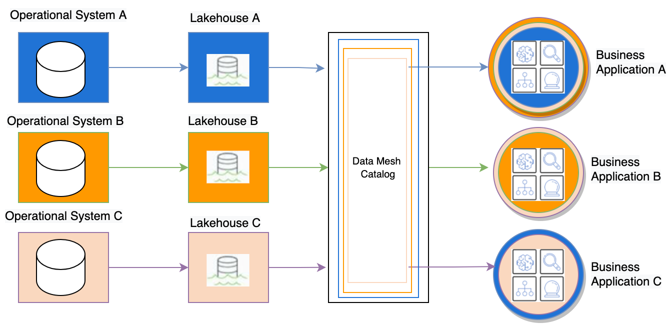
The following architecture diagram shows the high-level data mesh architecture we implemented at Fannie Mae. Data from each of the operational systems is collected and stored in individual lake houses and subscriptions are managed through a data mesh catalog in a centralized control plane account.

Fig 1. High level Data Mesh catalog architecture

Fig 1. High level Data Mesh catalog architecture

Control plane for data mesh

With a redesigned account structure, data are spread out across separate accounts for each business application area in S3 data lake or in Amazon Redshift cluster. We designed a hub and spoke point-to-point data distribution scheme with a centralized semantic search to enhance the data relevance. We use a centralized control plane account to store the catalog information, contract detail, approval workflow policies, and access management details for the data mesh. With a policy driven access paradigm, we enable fine-grained access management to the data, where we automated Data as a Service enablement with an optimized approach. It has three modules to store and manage catalog, contracts, and access management.

Data catalog

The data catalog provides the data glossary and catalog information, and helps fully satisfy governance and security standards. With AWS Glue crawlers, we create the catalog for the lake house in a centralized control plane account, and then we automate the sharing process in a secure manner. This enables a query-based framework to pinpoint the exact location of the data. The data catalog collects the runtime information about the datasets for indexing purposes, and provides runtime metrics for analytics on dataset usage and access patterns. The catalog also provides a mechanism to update the catalog through automation as new datasets become available.

Contract registry

The contract registry hosts the policy engine, and uses Amazon DynamoDB to store the registry policies. This has the details on entitlements to physical mapping of data, and workflows for the access management process. We also use this to store and maintain the registry of existing data contracts and enable audit capability to determine and monitor the access patterns. In addition, the contract registry serves as the store for state management functionality.

Access management automation

Controlling and managing access to the dataset is done through access management. This provides a just-in-time data access through IAM session policies using a persona-driven approach. The access management module also hosts event notification for data, such as frequency of access or number of reads, and we then harness this information for data access lifecycle management. This module plays a critical role in the state management and provides extensive logging and monitoring capabilities on the state of the data.

Process flow of data mesh using Amazon Redshift cross-account data sharing

The process flow starts with creating a catalog of all datasets available in the control plane account. Consumers can request access to the data through a web front-end catalog, and the approval process is triggered through the central control plane account. The following architecture diagram represents the high-level implementation of Amazon Redshift data sharing via the data mesh architecture. The steps of the process flow are as follows:

  1. All the data products, Amazon Redshift tables, and S3 buckets are registered in a centralized AWS Glue Data Catalog.
  2. Data scientists and LOB users can browse the Data Catalog to find the data products available across all lake houses in Fannie Mae.
  3. Business applications can consume the data in other lake houses by registering a consumer contract. For example, LOB1-Lakehouse can register the contract to utilize data from LOB3-Lakehouse.
  4. The contract is reviewed and approved by the data producer, which subsequently triggers a technical event via Amazon Simple Service Notification (Amazon SNS).
  5. The subscribing AWS Lambda function runs AWS CLI commands, ACLs, and IAM policies to set up Amazon Redshift data sharing and make data available for consumers.
  6. Consumers can access the subscribed Amazon Redshift cluster data using their own cluster.
Fig 2. Data Mesh architecture using Amazon Redshift data sharing

Fig 2. Data Mesh architecture using Amazon Redshift data sharing

The intention of this post is not to provide detailed steps for every aspect of creating the data mesh, but to provide a high-level overview of the architecture implemented, and how you can use various analytics services and third-party tools to create a scalable data mesh with Amazon Redshift and Amazon S3. If you want to try out creating this architecture, you can use these steps and automate the process using your tool of choice for the front-end user interface to enable users to subscribe to the dataset.

The steps we describe here are a simplified version of the actual implementation, so it doesn’t involve all the tools and accounts. To set up this scaled-down data mesh architecture, we demonstrate using cross-account data sharing using one control plane account and two consumer accounts. For this, you should have the following prerequisites:

  • Three AWS accounts, one for the producer <ProducerAWSAccount1>, and two consumer accounts: <ConsumerAWSAccount1> and <ConsumerAWSAccount2>
  • AWS permissions to provision Amazon Redshift and create an IAM role and policy
  • The required Amazon Redshift clusters: one for the producer in the producer AWS account, a cluster in ConsumerCluster1, and optionally a cluster in ConsumerCluster2
  • Two users in the producer account, and two users in consumer account 1:
    • ProducerClusterAdmin – The Amazon Redshift user with admin access on the producer cluster
    • ProducerCloudAdmin – The IAM user or role with rights to run authorize-data-share and deauthorize-data-share AWS CLI commands in the producer account
    • Consumer1ClusterAdmin – The Amazon Redshift user with admin access on the consumer cluster
    • Consumer1CloudAdmin – The IAM user or role with rights to run associate-data-share-consumer and disassociate-data-share-consumer AWS CLI commands in the consumer account

Implement the solution

On the Amazon Redshift console, log in to the producer cluster and run the following statements using the query editor:

CREATE DATASHARE ds;

ALTER DATASHARE ds ADD SCHEMA PUBLIC;
ALTER DATASHARE ds ADD TABLE table1;
ALTER DATASHARE ds ADD ALL TABLES IN SCHEMA sf_schema;

For sharing data across AWS accounts, you can use the following GRANT USAGE command. For authorizing the data share, typically it will be done by a manager or approver. In this case, we show how you can automate this process using the AWS CLI command authorize-data-share.

GRANT USAGE ON DATASHARE ds TO ACCOUNT <CONSUMER ACCOUNT>;

aws redshift authorize-data-share --data-share-arn <DATASHARE ARN> --consumer-identifier <CONSUMER ACCOUNT>

For the consumer to access the shared data from producer, an administrator on the consumer account needs to associate the data share with one or more clusters. This can be done using the Amazon Redshift console or AWS CLI commands. We provide the following AWS CLI command because this is how you can automate the process from the central control plane account:

aws redshift associate-data-share-consumer --no-associate-entire-account --data-share-arn <DATASHARE ARN> --consumer-arn <CONSUMER CLUSTER ARN>

/* Create Database in Consumer Account */
CREATE DATABASE ds_db FROM DATASHARE ds OF ACCOUNT <PRODUCER ACCOUNT> NAMESPACE <PRODUCER CLUSTER NAMESPACE>;

Optional:
CREATE EXTERNAL SCHEMA Schema_from_datashare FROM REDSHIFT DATABASE 'ds_db' SCHEMA 'public';

GRANT USAGE ON DATABASE ds_db TO user/group;

/* Optional:Grant usage on database to users or groups */
GRANT USAGE ON SCHEMA Schema_from_datashare TO GROUP Analyst_group;

To enable Amazon Redshift Spectrum cross-account access to AWS Glue and Amazon S3, and the IAM roles required, refer to How can I create Amazon Redshift Spectrum cross-account access to AWS Glue and Amazon S3.

Conclusion

Amazon Redshift data sharing provides a simple, seamless, and secure platform for sharing data in a domain-oriented distributed data mesh architecture. Fannie Mae deployed the Amazon Redshift data sharing capability across the data lake and data mesh platforms, which currently hosts over 4 petabytes worth of business data. The capability has been seamlessly integrated with their Just-In-Time (JIT) data provisioning framework enabling a single-click, persona-driven access to data. Further, Amazon Redshift data sharing coupled with Fannie Mae’s centralized, policy-driven data governance framework greatly simplified access to data in the lake ecosystem while fully conforming to the stringent data governance policies and standards. This demonstrates that Amazon Redshift users can create data share as product to distribute across many data domains.

In summary, Fannie Mae was able to successfully integrate the data sharing capability in their data ecosystem to bring efficiencies in data democratization and introduce a higher velocity, near real-time access to data across various business units. We encourage you to explore the data sharing feature of Amazon Redshift to build your own data mesh architecture and improve access to data for your business users.


About the authors

Kiran Ramineni is Fannie Mae’s Vice President Head of Single Family, Cloud, Data, ML/AI & Infrastructure Architecture, reporting to the CTO and Chief Architect. Kiran and team spear headed cloud scalable Enterprise Data Mesh (Data Lake) with support for Just-In-Time (JIT), and Zero Trust as it applies to Citizen Data Scientist and Citizen Data Engineers. In the past Kiran built/lead several internet scalable always-on platforms.

Basava Hubli is a Director & Lead Data/ML Architect at Enterprise Architecture. He oversees the Strategy and Architecture of Enterprise Data, Analytics and Data Science platforms at Fannie Mae. His primary focus is on Architecture Oversight and Delivery of Innovative technical capabilities that solve for critical Enterprise business needs. He leads a passionate and motivated team of architects who are driving the modernization and adoption of the Data, Analytics and ML platforms on Cloud. Under his leadership, Enterprise Architecture has successfully deployed several scalable, innovative platforms & capabilities that includes, a fully-governed Data Mesh which hosts peta-byte scale business data and a persona-driven, zero-trust based data access management framework which solves for the organization’s data democratization needs.

Rajesh Francis is a Senior Analytics Customer Experience Specialist at AWS. He specializes in Amazon Redshift and focuses on helping to drive AWS market and technical strategy for data warehousing and analytics. Rajesh works closely with large strategic customers to help them adopt our new services and features, develop long-term partnerships, and feed customer requirements back to our product development teams to guide the direction of our product offerings.

Kiran Sharma is a Senior Data Architect in AWS Professional Services. Kiran helps customers architecting, implementing and optimizing peta-byte scale Big Data Solutions on AWS.

Set up federated access to Amazon Athena for Microsoft AD FS users using AWS Lake Formation and a JDBC client

Post Syndicated from Mostafa Safipour original https://aws.amazon.com/blogs/big-data/set-up-federated-access-to-amazon-athena-for-microsoft-ad-fs-users-using-aws-lake-formation-and-a-jdbc-client/

Tens of thousands of AWS customers choose Amazon Simple Storage Service (Amazon S3) as their data lake to run big data analytics, interactive queries, high-performance computing, and artificial intelligence (AI) and machine learning (ML) applications to gain business insights from their data. On top of these data lakes, you can use AWS Lake Formation to ingest, clean, catalog, transform, and help secure your data and make it available for analysis and ML. Once you have setup your data lake, you can use Amazon Athena which is an interactive query service that makes it easy to analyze data in Amazon Simple Storage Service (Amazon S3) using standard SQL.

With Lake Formation, you can configure and manage fine-grained access control to new or existing databases, tables, and columns defined in the AWS Glue Data Catalog for data stored in Amazon S3. After you set access permissions using Lake Formation, you can use analytics services such as Amazon Athena, Amazon Redshift, and Amazon EMR without needing to configure policies for each service.

Many of our customers use Microsoft Active Directory Federation Services (AD FS) as their identity provider (IdP) while using cloud-based services. In this post, we provide a step-by-step walkthrough of configuring AD FS as the IdP for SAML-based authentication with Athena to query data stored in Amazon S3, with access permissions defined using Lake Formation. This enables end-users to log in to their SQL client using Active Directory credentials and access data with fine-grained access permissions.

Solution overview

To build the solution, we start by establishing trust between AD FS and your AWS account. With this trust in place, AD users can federate into AWS using their AD credentials and assume permissions of an AWS Identity and Access Management (IAM) role to access AWS resources such as the Athena API.

To create this trust, you add AD FS as a SAML provider into your AWS account and create an IAM role that federated users can assume. On the AD FS side, you add AWS as a relying party and write SAML claim rules to send the right user attributes to AWS (specifically Lake Formation) for authorization purposes.

The steps in this post are structured into the following sections:

  1. Set up an IAM SAML provider and role.
  2. Configure AD FS.
  3. Create Active Directory users and groups.
  4. Create a database and tables in the data lake.
  5. Set up the Lake Formation permission model.
  6. Set up a SQL client with JDBC connection.
  7. Verify access permissions.

The following diagram provides an overview of the solution architecture.

The flow for the federated authentication process is as follows:

  1. The SQL client which has been configured with Active Directory credentials sends an authentication request to AD FS.
  2. AD FS authenticates the user using Active Directory credentials, and returns a SAML assertion.
  3. The client makes a call to Lake Formation, which initiates an internal call with AWS Security Token Service (AWS STS) to assume a role with SAML for the client.
  4. Lake Formation returns temporary AWS credentials with permissions of the defined IAM role to the client.
  5. The client uses the temporary AWS credentials to call the Athena API StartQueryExecution.
  6. Athena retrieves the table and associated metadata from the AWS Glue Data Catalog.
  7. On behalf of the user, Athena requests access to the data from Lake Formation (GetDataAccess). Lake Formation assumes the IAM role associated with the data lake location and returns temporary credentials.
  8. Athena uses the temporary credentials to retrieve data objects from Amazon S3.
  9. Athena returns the results to the client based on the defined access permissions.

For our use case, we use two sample tables:

  • LINEORDER – A fact table containing orders
  • CUSTOMER – A dimension table containing customer information including Personally Identifiable Information (PII) columns (c_name, c_phone, c_address)

We also have data consumer users who are members of the following teams:

  • CustomerOps – Can see both orders and customer information, including PII attributes of the customer
  • Finance – Can see orders for analytics and aggregation purposes but only non-PII attributes of the customer

To demonstrate this use case, we create two users called CustomerOpsUser and FinanceUser and three AD groups for different access patterns: data-customer (customer information access excluding PII attributes), data-customer-pii (full customer information access including PII attributes), and data-order (order information access). By adding the users to these three groups, we can grant the right level of access to different tables and columns.

Prerequisites

To follow along with this walkthrough, you must meet the following prerequisites:

Set up an IAM SAML provider and role

To set up your SAML provider, complete the following steps:

  1. In the IAM console, choose Identity providers in the navigation pane.
  2. Choose Add provider.
  3. For Provider Type, choose SAML.
  4. For Provider Name, enter adfs-saml-provider.
  5. For Metadata Document, download your AD FS server’s federation XML file by entering the following address in a browser with access to the AD FS server:
    https://<adfs-server-name>/FederationMetadata/2007-06/FederationMetadata.xml

  6. Upload the file to AWS by choosing Choose file.
  7. Choose Add provider to finish.

Now you’re ready to create a new IAM role.

  1. In the navigation pane, choose Roles.
  2. Choose Create role.
  3. For the type of trusted entity, choose SAML 2.0 federation.
  4. For SAML provider, choose the provider you created (adfs-saml-provider).
  5. Choose Allow programmatic and AWS Management Console access.
  6. The Attribute and Value fields should automatically populate with SAML:aud and https://signin.aws.amazon.com/saml.
  7. Choose Next:Permissions.
  8. Add the necessary IAM permissions to this role. For this post, attach AthenaFullAccess.

If the Amazon S3 location for your Athena query results doesn’t start with aws-athena-query-results, add another policy to allow users write query results into your Amazon S3 location. For more information, see Specifying a Query Result Location Using the Athena Console and Writing IAM Policies: How to Grant Access to an Amazon S3 Bucket.

  1. Leave the defaults in the next steps and for Role name, enter adfs-data-access.
  2. Choose Create role.
  3. Take note of the SAML provider and IAM role names to use in later steps when creating the trust between the AWS account and AD FS.

Configure AD FS

SAML-based federation has two participant parties: the IdP (Active Directory) and the relying party (AWS), which is the service or application that wants to use authentication from the IdP.

To configure AD FS, you first add a relying party trust, then you configure SAML claim rules for the relying party. Claim rules are the way that AD FS forms a SAML assertion sent to a relying party. The SAML assertion states that the information about the AD user is true, and that it has authenticated the user.

Add a relying party trust

To create your relying party in AD FS, complete the following steps:

  1. Log in to the AD FS server.
  2. On the Start menu, open ServerManger.
  3. On the Tools menu, choose the AD FS Management console.
  4. Under Trust Relationships in the navigation pane, choose Relying Party Trusts.
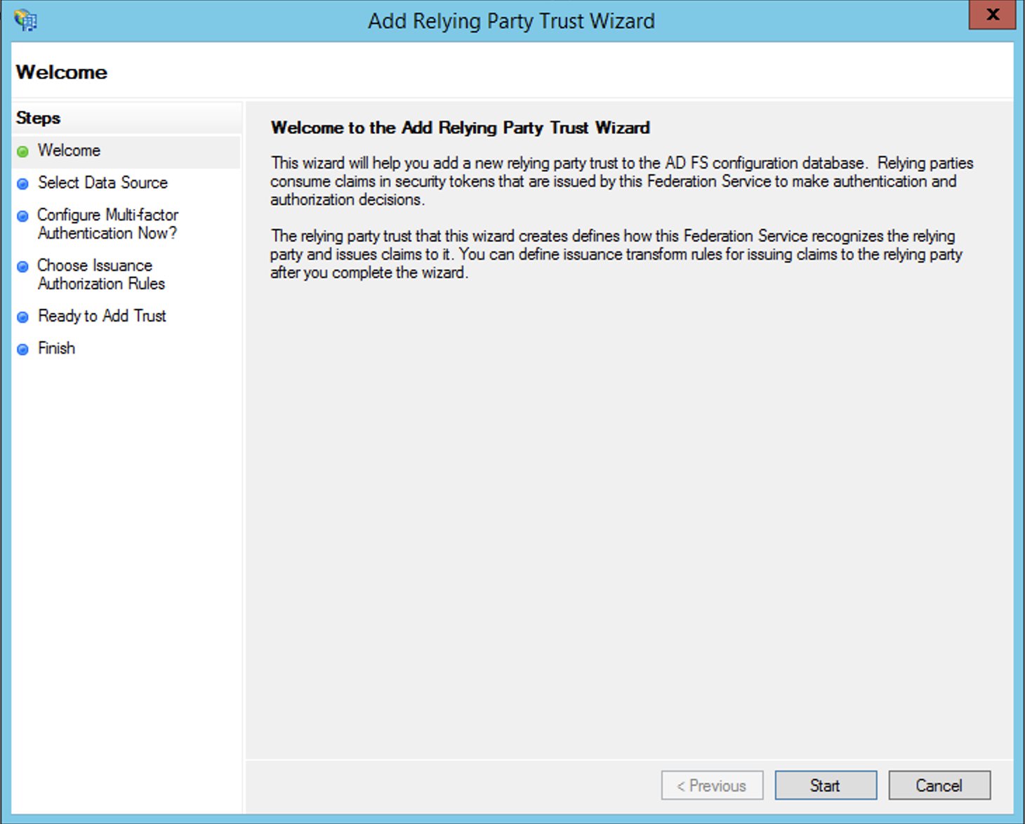
  5. Choose Add Relying Party Trust.
  6. Choose Start.
  7. Select Import data about the relying party published online or on a local network and enter the URL https://signin.aws.amazon.com/static/saml-metadata.xml.

The metadata XML file is a standard SAML metadata document that describes AWS as a relying party.

  1. Choose Next.
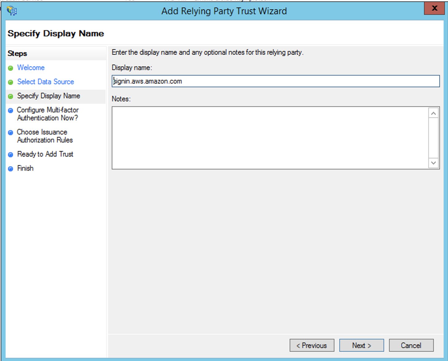
  2. For Display name, enter a name for your relying party.
  3. Choose Next.
  4. Select I do not want to configure multi-factor authentication.

For increased security, we recommend that you configure multi-factor authentication to help protect your AWS resources. We don’t enable multi-factor authentication for this post because we’re using a sample dataset.

  1. Choose Next.
  2. Select Permit all users to access this relying party and choose Next.

This allows all users in Active Directory to use AD FS with AWS as a relying party. You should consider your security requirements and adjust this configuration accordingly.

  1. Finish creating your relying party.

Configure SAML claim rules for the relying party

You create two sets of claim rules in this post. The first set (rules 1–4) contains AD FS claim rules that are required to assume an IAM role based on AD group membership. These are the rules that you also create if you want to establish federated access to the AWS Management Console. The second set (rules 5–6) are claim rules that are required for Lake Formation fine-grained access control.

To create AD FS claim rules, complete the following steps:

  1. On the AD FS Management console, find the relying party you created in the previous step.
  2. Right-click the relying party and choose Edit Claim Rules.
  3. Choose Add Rule and create your six new rules.
  4. Create claim rule 1, called NameID:
    1. For Rule template, use Transform an Incoming Claim.
    2. For Incoming claim type, choose Windows account name.
    3. For Outgoing claim type, choose Name ID.
    4. For Outgoing name ID format, choose Persistent Identifier.
    5. Select Pass through all claim values.
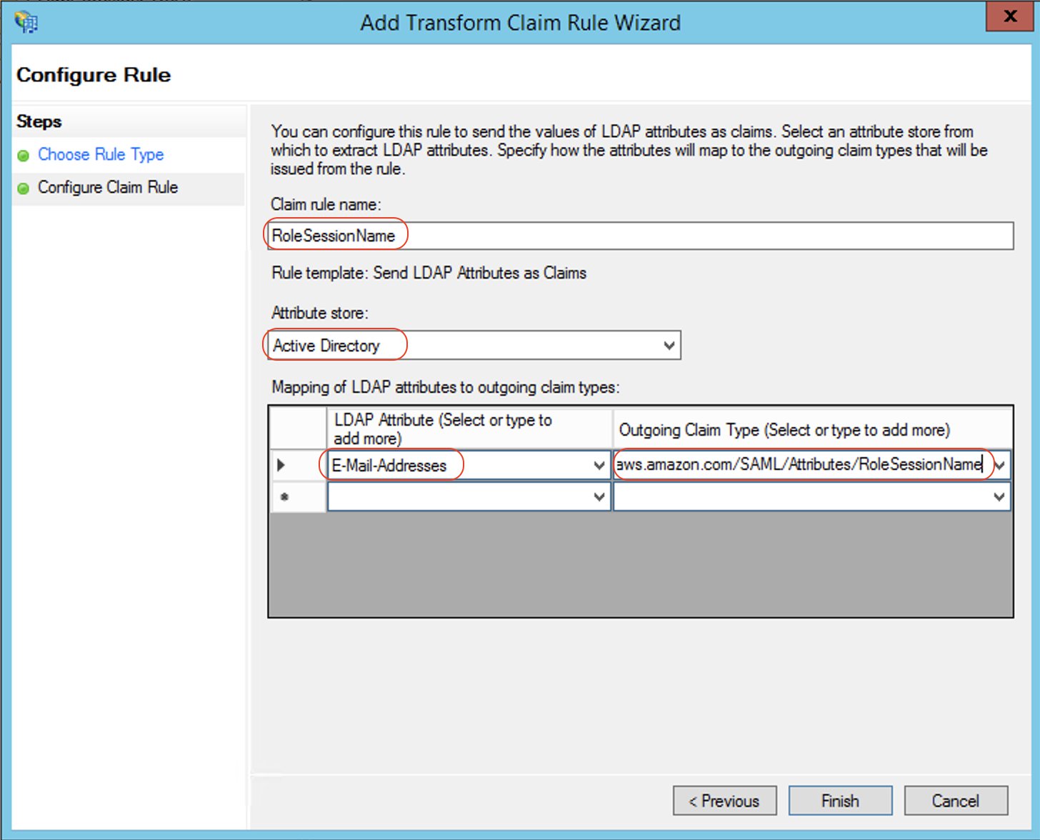
  5. Create claim rule 2, called RoleSessionName:
    1. For Rule template, use Send LDAP Attribute as Claims.
    2. For Attribute store, choose Active Directory.
    3. For Mapping of LDAP attributes to outgoing claim types, add the attribute E-Mail-Addresses and outgoing claim type https://aws.amazon.com/SAML/Attributes/RoleSessionName.
  6. Create claim rule 3, called Get AD Groups:
    1. For Rule template, use Send Claims Using a Custom Rule.
    2. For Custom rule, enter the following code:
      c:[Type == "http://schemas.microsoft.com/ws/2008/06/identity/claims/windowsaccountname", Issuer == "AD AUTHORITY"]
      => add(store = "Active Directory", types = ("http://temp/variable"), query = ";tokenGroups;{0}", param = c.Value);

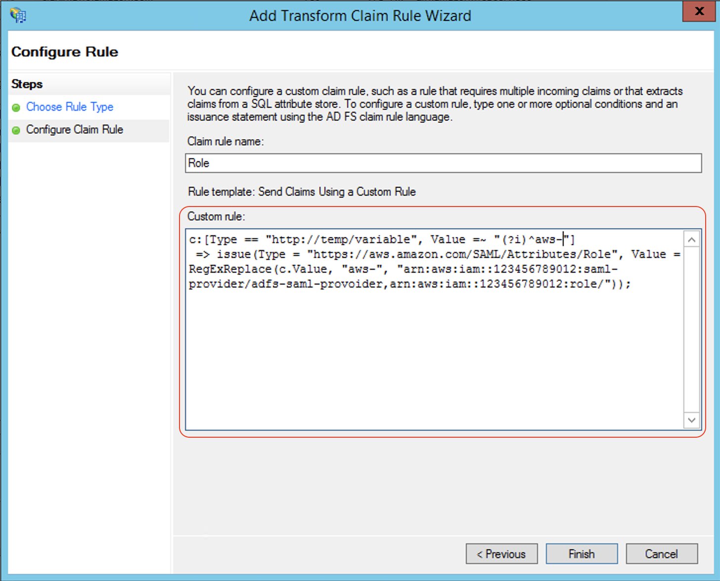
  7. Create claim rule 4, called Roles:
    1. For Rule template, use Send Claims Using a Custom Rule.
    2. For Custom rule, enter the following code (enter your account number and name of the SAML provider you created earlier):
      c:[Type == "http://temp/variable", Value =~ "(?i)^aws-"]
      => issue(Type = "https://aws.amazon.com/SAML/Attributes/Role", Value = RegExReplace(c.Value, "aws-", "arn:aws:iam::<AWS ACCOUNT NUMBER>:saml-provider/<adfs-saml-provider>,arn:aws:iam::<AWS ACCOUNT NUMBER>:role/"));

Claim rules 5 and 6 allow Lake Formation to make authorization decisions based on user name or the AD group membership of the user.

  1. Create claim rule 5, called LF-UserName, which passes the user name and SAML assertion to Lake Formation:
    1. For Rule template, use Send LDAP Attributes as Claims.
    2. For Attribute store, choose Active Directory.
    3. For Mapping of LDAP attributes to outgoing claim types, add the attribute User-Principal-Name and outgoing claim type https://lakeformation.amazon.com/SAML/Attributes/Username.
  2. Create claim rule 6, called LF-Groups, which passes data and analytics-related AD groups that the user is a member of, along with the SAML assertion to Lake Formation:
    1. For Rule template, use Send Claims Using a Custom Rule.
    2. For Custom rule, enter the following code:
      c:[Type == "http://temp/variable", Value =~ "(?i)^data-"]
      => issue(Type = "https://lakeformation.amazon.com/SAML/Attributes/Groups", Value = c.Value);

The preceding rule snippet filters AD group names starting with data-. This is an arbitrary naming convention; you can adopt your preferred naming convention for AD groups that are related to data lake access.

Create Active Directory users and groups

In this section, we create two AD users and required AD groups to demonstrate varying levels of access to the data.

Create users

You create two AD users: FinanceUser and CustomerOpsUser. Each user corresponds to an individual who is a member of the Finance or Customer business units. The following table summarizes the details of each user.


FinanceUser CustomerOpsUser
First Name FinanceUser CustomerOpsUser
User logon name [email protected] [email protected]
Email [email protected] [email protected]

To create your users, complete the following steps:

  1. On the Server Manager Dashboard, on the Tools menu, choose Active Directory Users and Computers.
  2. In the navigation pane, choose Users.
  3. On the tool bar, choose the Create user icon.
  4. For First name, enter FinanceUser.
  5. For Full name, enter FinanceUser.
  6. For User logon name, enter [email protected].
  7. Choose Next.
  8. Enter a password and deselect User must change password at next logon.

We choose this option for simplicity, but in real-world scenarios, newly created users must change their password for security reasons.

  1. Choose Next.
  2. In Active Directory Users and Computers, choose the user name.
  3. For Email, enter [email protected].

Adding an email is mandatory because it’s used as the RoleSessionName value in the SAML assertion.

  1. Choose OK.
  2. Repeat these steps to create CustomerOpsUser.

Create AD groups to represent data access patterns

Create the following AD groups to represent three different access patterns and also the ability to assume an IAM role:

  • data-customer – Members have access to non-PII columns of the customer table
  • data-customer-pii – Members have access to all columns of the customer table, including PII columns
  • data-order – Members have access to the lineorder table
  • aws-adfs-data-access – Members assume the adfs-data-access IAM role when logging in to AWS

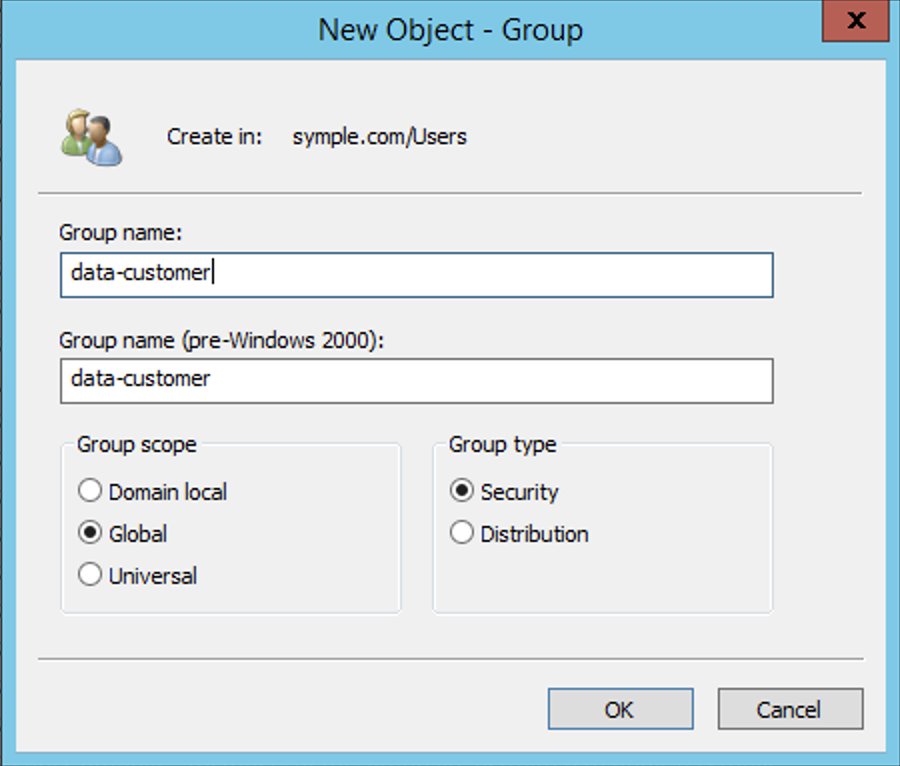
To create the groups, complete the following steps:

  1. On the Server Manager Dashboard, on the Tools menu, choose Active Directory Users and Computers.
  2. On the tool bar, choose the Create new group icon.
  3. For Group name¸ enter data-customer.
  4. For Group scope, select Global.
  5. For Group type¸ select Security.
  6. Choose OK.
  7. Repeat these steps to create the remaining groups.

Add users to appropriate groups

Now you add your newly created users to their appropriate groups, as detailed in the following table.

User Group Membership Description
CustomerOpsUser data-customer-pii
data-order
aws-adfs-data-access
Sees all customer information including PII and their orders
FinanceUser data-customer
data-order
aws-adfs-data-access
Sees only non-PII customer data and orders

Complete the following steps:

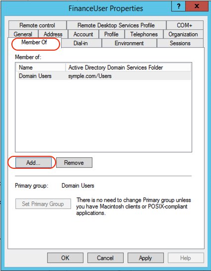
  1. On the Server Manager Dashboard, on the Tools menu, choose Active Directory Users and Computers.
  2. Choose the user FinanceUser.
  3. On the Member Of tab, choose Add.
  4. Add the appropriate groups.
  5. Repeat these steps for CustomerOpsUser.

Create a database and tables in the data lake

In this step, you copy data files to an S3 bucket in your AWS account by running the following AWS Command Line Interface (AWS CLI) commands. For more information on how to set up the AWS CLI, refer to Configuration Basics.

These commands copy the files that contain data for customer and lineorder tables. Replace <BUCKET NAME> with the name of an S3 bucket in your AWS account.

aws s3 sync s3://awssampledb/load/ s3://<BUCKET NAME>/customer/ \
--exclude "*" --include "customer-fw.tbl-00*" --exclude "*.bak"

aws s3api copy-object --copy-source awssampledb/load/lo/lineorder-single.tbl000.gz \
--key lineorder/lineorder-single.tbl000.gz --bucket <BUCKET NAME> \
--tagging-directive REPLACE

For this post, we use the default settings for storing data and logging access requests within Amazon S3. You can enhance the security of your sensitive data with the following methods:

  • Implement encryption at rest using AWS Key Management Service (AWS KMS) and customer managed encryption keys
  • Use AWS CloudTrail and audit logging
  • Restrict access to AWS resources based on the least privilege principle

Additionally, Lake Formation is integrated with CloudTrail, a service that provides a record of actions taken by a user, role, or AWS service in Lake Formation. CloudTrail captures all Lake Formation API calls as events and is enabled by default when you create a new AWS account. When activity occurs in Lake Formation, that activity is recorded as a CloudTrail event along with other AWS service events in event history. For audit and access monitoring purposes, all federated user logins are logged via CloudTrail under the AssumeRoleWithSAML event name. You can also view specific user activity based on their user name in CloudTrail.

To create a database and tables in the Data Catalog, open the query editor on the Athena console and enter the following DDL statements. Replace <BUCKET NAME> with the name of the S3 bucket in your account.

CREATE DATABASE salesdata;
CREATE EXTERNAL TABLE salesdata.customer
(
    c_custkey VARCHAR(10),
    c_name VARCHAR(25),
    c_address VARCHAR(25),
    c_city VARCHAR(10),
    c_nation VARCHAR(15),
    c_region VARCHAR(12),
    c_phone VARCHAR(15),
    c_mktsegment VARCHAR(10)
)
-- The data files contain fixed width columns hence using RegExSerDe
ROW FORMAT SERDE 'org.apache.hadoop.hive.serde2.RegexSerDe'
WITH SERDEPROPERTIES (
    "input.regex" = "(.{10})(.{25})(.{25})(.{10})(.{15})(.{12})(.{15})(.{10})"
)
LOCATION 's3://<BUCKET NAME>/customer/';

CREATE EXTERNAL TABLE salesdata.lineorder(
  `lo_orderkey` int, 
  `lo_linenumber` int, 
  `lo_custkey` int, 
  `lo_partkey` int, 
  `lo_suppkey` int, 
  `lo_orderdate` int, 
  `lo_orderpriority` varchar(15), 
  `lo_shippriority` varchar(1), 
  `lo_quantity` int, 
  `lo_extendedprice` int, 
  `lo_ordertotalprice` int, 
  `lo_discount` int, 
  `lo_revenue` int, 
  `lo_supplycost` int, 
  `lo_tax` int, 
  `lo_commitdate` int, 
  `lo_shipmode` varchar(10))
ROW FORMAT DELIMITED 
  FIELDS TERMINATED BY '|' 
LOCATION 's3://<BUCKET NAME>/lineorder/';

Verify that tables are created and you can see the data:

SELECT * FROM "salesdata"."customer" limit 10;
SELECT * FROM "salesdata"."lineorder" limit 10;

Set up the Lake Formation permission model

Lake Formation uses a combination of Lake Formation permissions and IAM permissions to achieve fine-grained access control. The recommended approach includes the following:

  • Coarse-grained IAM permissions – These apply to the IAM role that users assume when running queries in Athena. IAM permissions control access to Lake Formation, AWS Glue, and Athena APIs.
  • Fine-grained Lake Formation grants – These control access to Data Catalog resources, Amazon S3 locations, and the underlying data at those locations. With these grants, you can give access to specific tables or only columns that contain specific data values.

Configure IAM role permissions

Earlier in the walkthrough, you created the IAM role adfs-data-access and attached the AWS managed IAM policy AthenaFullAccess to it. This policy has all the permissions required for the purposes of this post.

For more information, see the Data Analyst Permissions section in Lake Formation Personas and IAM Permissions Reference.

Register an S3 bucket as a data lake location

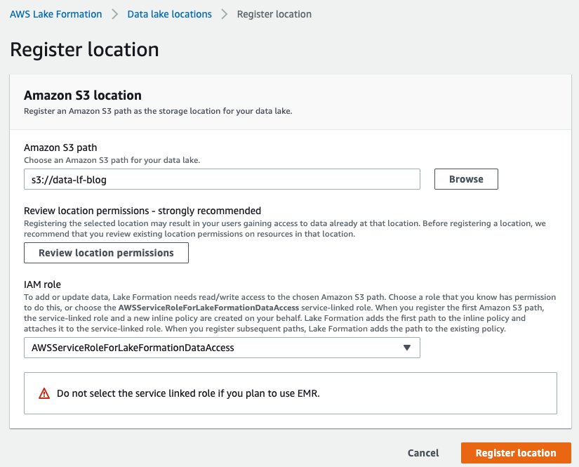
The mechanism to govern access to an Amazon S3 location using Lake Formation is to register a data lake location. Complete the following steps:

  1. On the Lake Formation console, choose Data lake locations.
  2. Choose Register location.
  3. For Amazon S3 path, choose Browse and locate your bucket.
  4. For IAM role, choose AWSServiceRoleForLakeFormationDataAccess.

In this step, you specify an IAM service-linked role, which Lake Formation assumes when it grants temporary credentials to integrated AWS services that access the data in this location. This role and its permissions are managed by Lake Formation and can’t be changed by IAM principals.

  1. Choose Register location.

Configure data permissions

Now that you have registered the Amazon S3 path, you can give AD groups appropriate permissions to access tables and columns in the salesdata database. The following table summarizes the new permissions.

Database and Table AD Group Name Table Permissions Data Permissions
salesdata.customer data-customer Select c_city, c_custkey, c_mktsegment, c_nation, and c_region
salesdata.customer data-customer-pii Select All data access
salesdata.lineorder data-order Select All data access
  1. On the Lake Formation console, choose Tables in the navigation pane.
  2. Filter tables by the salesdata database.
  3. Select the customer table and on the Actions menu, choose View permissions.

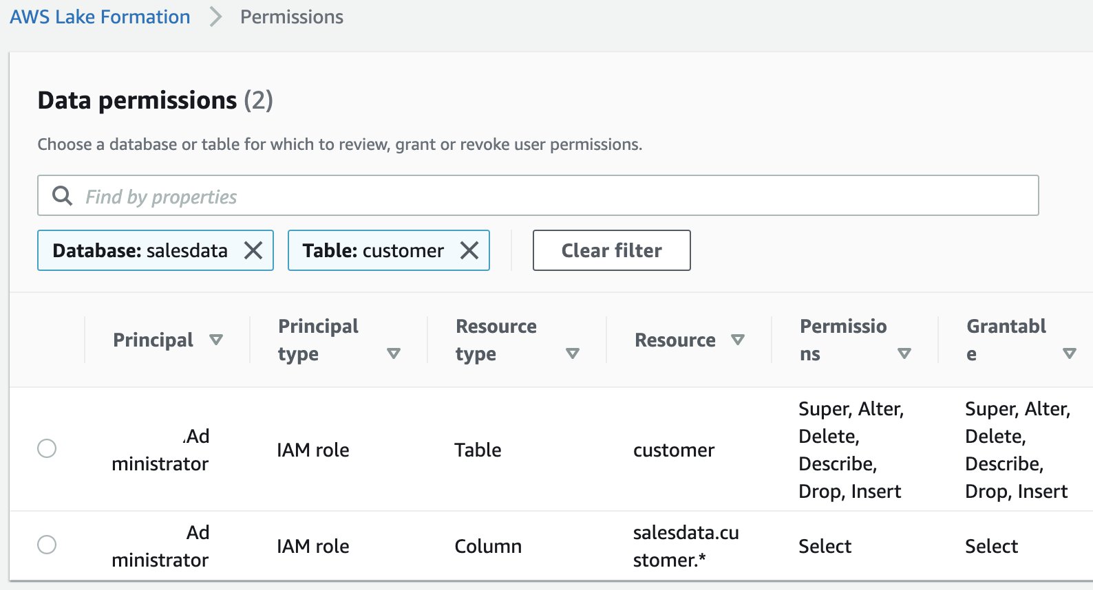
You should see following existing permissions. These entries allow the current data lake administrator to access the table and all its columns.

  1. To add new permissions, select the table and on the Actions menu, choose Grant.
  2. Select SAML user and groups.
  3. For SAML and Amazon QuickSight users and groups, enter arn:aws:iam::<AWS ACCOUNT NUMBER>:saml-provider/adfs-saml-provider:group/data-customer.

To get this value, get the ARN of the SAML provider from the IAM console and append :group/data-customer to the end of it.

  1. Select Named data catalog resources.
  2. For Databases, choose the salesdata database.
  3. For Tables, choose the customer table.
  4. For Table permissions, select Select.
  5. For Data permissions, select Column-based access.
  6. For Select columns, add the columns c_city, c_custkey, c_mktsegment, c_nation, and c_region.
  7. Choose Grant.

You have now allowed members of the AD group data-customer to have access to columns of the customer table that don’t include PII.

  1. Repeat these steps for the customer table and data-customer-pii group with all data access.
  2. Repeat these steps for the lineorder table and data-order group with all data access.

Set up a SQL client with JDBC connection and verify permissions

In this post, we use SQL Workbench to access Athena through AD authentication and verify the Lake Formation permissions you created in the previous section.

Prepare the SQL client

To set up the SQL client, complete the following steps:

  1. Download and extract the Lake Formation-compatible Athena JDBC driver with AWS SDK (2.0.14 or later version) from Using Athena with the JDBC Driver.
  2. Go to the SQL Workbench/J website and download the latest stable package.
  3. Install SQL Workbench/J on your client computer.
  4. In SQL Workbench, on the File menu, choose Manage Drivers.
  5. Choose the New driver icon.
  6. For Name, enter Athena JDBC Driver.
  7. For Library, browse to and choose the Simba Athena JDBC .jar file that you just downloaded.
  8. Choose OK.

You’re now ready to create connections in SQL Workbench for your users.

Create connections in SQL Workbench

To create your connections, complete the following steps:

  1. On the File menu, choose Connect.
  2. Enter the name Athena-FinanceUser.
  3. For Driver, choose the Simba Athena JDBC driver.
  4. For URL, enter the following code (replace the placeholders with actual values from your setup and remove the line breaks to make a single line connection string):
jdbc:awsathena://AwsRegion=<AWS Region Name e.g. ap-southeast-2>;
S3OutputLocation=s3://<Athena Query Result Bucket Name>/jdbc;
plugin_name=com.simba.athena.iamsupport.plugin.AdfsCredentialsProvider;
idp_host=<adfs-server-name e.g. adfs.company.com>;
idp_port=443;
preferred_role=<ARN of the role created in step1 e.g. arn>;
user=financeuser@<Domain Name e.g. company.com>;
password=<password>;
SSL_Insecure=true;
LakeFormationEnabled=true;

For this post, we used a self-signed certificate with AD FS. This certificate is not trusted by the client, therefore authentication doesn’t succeed. This is why the SSL_Insecure attribute is set to true to allow authentication despite the self-signed certificate. In real-world setups, you would use valid trusted certificates and can remove the SSL_Insecure attribute.

  1. Create a new SQL workbench profile named Athena-CustomerOpsUser and repeat the earlier steps with CustomerOpsUser in the connection URL string.
  2. To test the connections, choose Test for each user, and confirm that the connection succeeds.

Verify access permissions

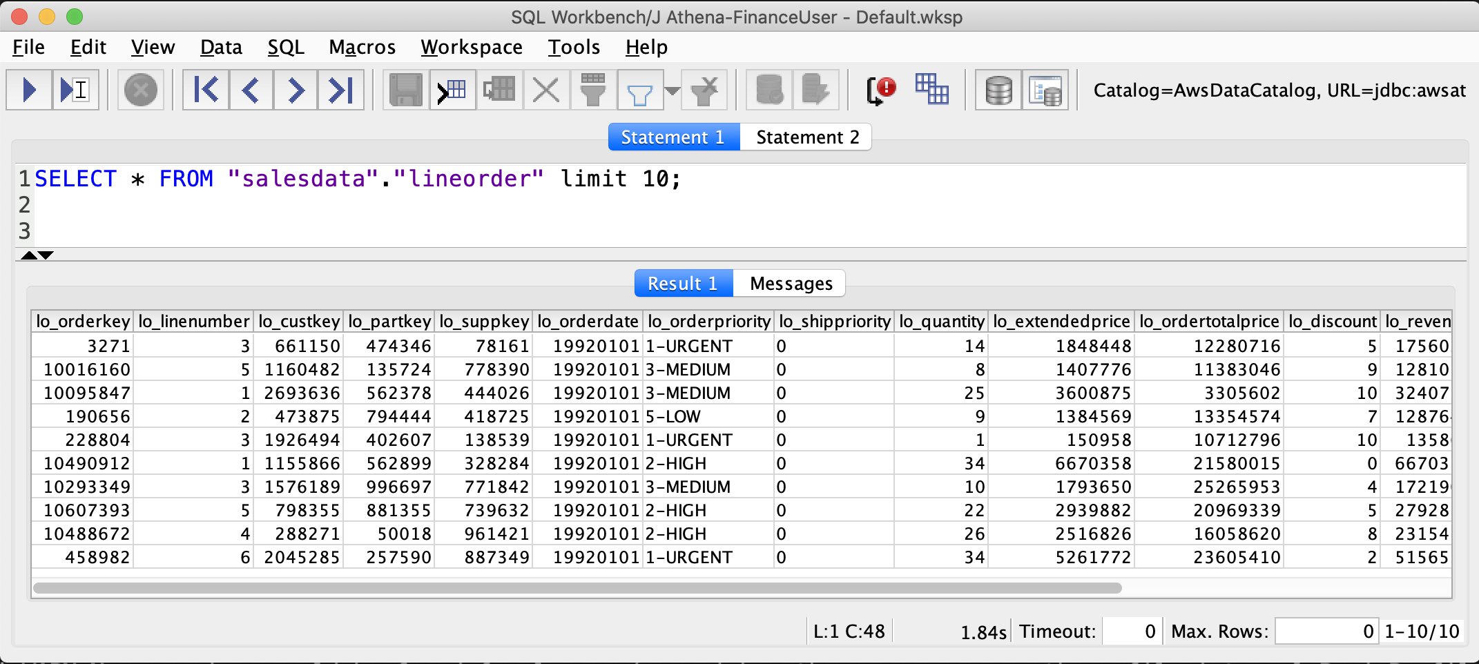
Now we can verify permissions for FinanceUser. In the SQL Workbench Statement window, run the following SQL SELECT statement:

SELECT * FROM "salesdata"."lineorder" limit 10;
SELECT * FROM "salesdata"."customer" limit 10;

Verify that only non-PII columns are returned from the customer table.

As you see in the preceding screenshots, FinanceUser only has access to non-PII columns of the customer table and full access to (all columns) of the lineorder table. This allows FinanceUser, for example, to run aggregate and summary queries based on market segment or location of customers without having access to their personal information.

Run a similar query for CustomerOpsUser. You should be able to see all columns, including columns containing PII, in the customer table.

Conclusion

This post demonstrated how to configure your data lake permissions using Lake Formation for AD users and groups. We configured AD FS 3.0 on your Active Directory and used it as an IdP to federate into AWS using SAML. This post also showed how you can integrate your Athena JDBC driver to AD FS and use your AD credentials directly to connect to Athena.

Integrating your Active Directory with the Athena JDBC driver gives you the flexibility to access Athena from business intelligence tools you’re already familiar with to analyze the data in your Amazon S3 data lake. This enables you to have a consistent central permission model that is managed through AD users and their group memberships.


About the Authors

Mostafa Safipour is a Solutions Architect at AWS based out of Sydney. Over the past decade he has helped many large organizations in the ANZ region build their data, digital, and enterprise workloads on AWS.

Praveen Kumar is a Specialist Solution Architect at AWS with expertise in designing, building, and implementing modern data and analytics platforms using cloud-native services. His areas of interests are serverless technology, streaming applications, and modern cloud data warehouses.
Amazon Redshift data sharing best practices and considerations

Post Syndicated from BP Yau original https://aws.amazon.com/blogs/big-data/amazon-redshift-data-sharing-best-practices-and-considerations/

Amazon Redshift is a fast, fully managed cloud data warehouse that makes it simple and cost-effective to analyze all your data using standard SQL and your existing business intelligence (BI) tools. Amazon Redshift data sharing allows for a secure and easy way to share live data for reading across Amazon Redshift clusters. It allows an Amazon Redshift producer cluster to share objects with one or more Amazon Redshift consumer clusters for read purposes without having to copy the data. With this approach, workloads isolated to different clusters can share and collaborate frequently on data to drive innovation and offer value-added analytic services to your internal and external stakeholders. You can share data at many levels, including databases, schemas, tables, views, columns, and user-defined SQL functions, to provide fine-grained access controls that can be tailored for different users and businesses that all need access to Amazon Redshift data. The feature itself is simple to use and integrate into existing BI tools.

In this post, we discuss Amazon Redshift data sharing, including some best practices and considerations.

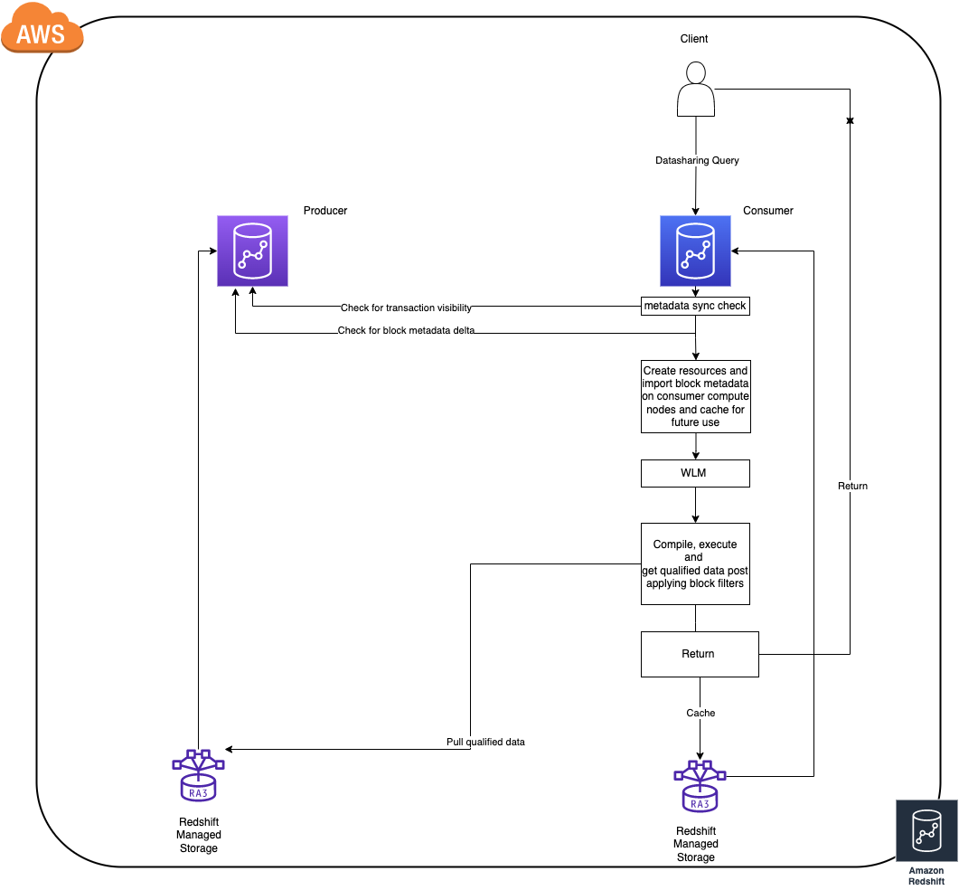
How does Amazon Redshift data sharing work ?

  • To achieve best in class performance Amazon Redshift consumer clusters cache and incrementally update block level data (let us refer to this as block metadata) of objects that are queried, from the producer cluster (this works even when cluster is paused).
  • The time taken for caching block metadata depends on the rate of the data change on the producer since the respective object(s) were last queried on the consumer. (As of today the consumer clusters only update their metadata cache for an object only on demand i.e. when queried)
  • If there are frequent DDL operations, the consumer is forced to re-cache the full block metadata for an object during the next access to maintain consistency as to enable live sharing as structure changes on the producer invalidate all the existing metadata cache on the consumers.
  • Once the consumer has the block metadata in sync with the latest state of an object on the producer that is when the query would execute as any other regular query (query referring to local objects).

Now that we have the necessary background on data sharing and how it works, let’s look at a few best practices across streams that can help improve workloads while using data sharing.

Security

In this section, we share some best practices for security when using Amazon Redshift data sharing.

Use INCLUDE NEW cautiously

INCLUDE NEW is a very useful setting while adding a schema to a data share (ALTER DATASHARE). If set to TRUE, this automatically adds all the objects created in the future in the specified schema to the data share automatically. This might not be ideal in cases where you want to have fine-grained control on objects being shared. In these cases, leave the setting at its default of FALSE.

Use views to achieve fine-grained access control

To achieve fine-grained access control for data sharing, you can create late-binding views or materialized views on shared objects on the consumer, and then share the access to these views to users on consumer cluster, instead of giving full access on the original shared objects. This comes with its own set of considerations, which we explain later in this post.

Audit data share usage and changes

Amazon Redshift provides an efficient way to audit all the activity and changes with respect to a data share using system views. We can use the following views to check these details:

Performance

In this section, we discuss best practices related to performance.

Materialized views in data sharing environments

Materialized views (MVs) provide a powerful route to precompute complex aggregations for use cases where high throughput is needed, and you can directly share a materialized view object via data sharing as well.

For materialized views built on tables where there are frequent write operations, it’s ideal to create the materialized view object on the producer itself and share the view. This method gives us the opportunity to centralize the management of the view on the producer cluster itself.

For slowly changing data tables, you can share the table objects directly and build the materialized view on the shared objects directly on the consumer. This method gives us the flexibility of creating a customized view of data on each consumer according to your use case.

This can help optimize the block metadata download and caching times in the data sharing query lifecycle. This also helps in materialized view refreshes because, as of this writing, Redshift doesn’t support incremental refresh for MVs built on shared objects.

Factors to consider when using cross-Region data sharing

Data sharing is supported even if the producer and consumer are in different Regions. There are a few differences we need to consider while implementing a share across Regions:

  • Consumer data reads are charged at $5/TB for cross region data shares, Data sharing within the same Region is free. For more information, refer to Managing cost control for cross-Region data sharing.
  • Performance will also vary when compared to a uni-Regional data share because the block metadata exchange and data transfer process between the cross-Regional shared clusters will take more time due to network throughput.

Metadata access

There are many system views that help with fetching the list of shared objects a user has access to. Some of these include all the objects from the database that you’re currently connected to, including objects from all the other databases that you have access to on the cluster, including external objects. The views are as follows:

We suggest using very restrictive filtering while querying these views because a simple select * will result in an entire catalog read, which isn’t ideal. For example, take the following query:

select * from svv_all_tables;

This query will try to collect metadata for all the shared and local objects, making it very heavy in terms of metadata scans, especially for shared objects.

The following is a better query for achieving a similar result:

SELECT table_name,
column_name,
data_type FROM svv_all_tables WHERE table_name = < tablename > AND schema_name = < schemaname > AND database_name = < databasename > ORDER BY ordinal_position

This is a good practice to follow for all metadata views and tables; doing so allows seamless integration into several tools. You can also use the SVV_DATASHARE* system views to exclusively see shared object-related information.

Producer/consumer dependencies

In this section, we discuss the dependencies between the producer and consumer.

Impact of the consumer on the producer

Queries on the consumer cluster will have no impact in terms of performance or activity on the producer cluster. This is why we can achieve true workload isolation using data sharing.

Encrypted producers and consumers

Data sharing seamlessly integrates even if both the producer and the consumer are encrypted using different AWS Key Management Service (AWS KMS) keys. There are sophisticated, highly secure key exchange protocols to facilitate this so you don’t have to worry about encryption at rest and other compliance dependencies. The only thing to make sure is that both the producer and consumer are in a homogeneous encryption configuration.

Data visibility and consistency

A data sharing query on the consumer can’t impact the transaction semantics on the producer. All the queries involving shared objects on the consumer cluster follow read-committed transaction consistency while checking for visible data for that transaction.

Maintenance

If there is a scheduled manual VACUUM operation in use for maintenance activities on the producer cluster on shared objects, you should use VACUUM recluster whenever possible. This is especially important for large objects because it has optimizations in terms of the number of data blocks the utility interacts with, which results in less block metadata churn compared to a full vacuum. This benefits the data sharing workloads by reducing the block metadata sync times.

Add-ons

In this section, we discuss additional add-on features for data sharing in Amazon Redshift.

Real-time data analytics using Amazon Redshift streaming data

Amazon Redshift recently announced the preview for streaming ingestion using Amazon Kinesis Data Streams. This eliminates the need for staging the data and helps achieve low-latency data access. The data generated via streaming on the Amazon Redshift cluster is exposed using a materialized view. You can share this as any other materialized view via a data share and use it to set up low-latency shared data access across clusters in minutes.

Amazon Redshift concurrency scaling to improve throughput

Amazon Redshift data sharing queries can utilize concurrency scaling to improve the overall throughput of the cluster. You can enable concurrency scaling on the consumer cluster for queues where you expect a heavy workload to improve the overall throughput when the cluster is experiencing heavy load.

For more information about concurrency scaling, refer to Data sharing considerations in Amazon Redshift.

Amazon Redshift Serverless

Amazon Redshift Serverless clusters are ready for data sharing out of the box. A serverless cluster can also act as a producer or a consumer for a provisioned cluster. The following are the supported permutations with Redshift Serverless:

  • Serverless (producer) and provisioned (consumer)
  • Serverless (producer) and serverless (consumer)
  • Serverless (consumer) and provisioned (producer)

Conclusion

Amazon Redshift data sharing gives you the ability to fan out and scale complex workloads without worrying about workload isolation. However, like any system, not having the right optimization techniques in place could pose complex challenges in the long term as the systems grow in scale. Incorporating the best practices listed in this post presents a way to mitigate potential performance bottlenecks proactively in various areas.

Try data sharing today to unlock the full potential of Amazon Redshift, and please don’t hesitate to reach out to us in case of further questions or clarifications.


About the authors

BP Yau is a Sr Product Manager at AWS. He is passionate about helping customers architect big data solutions to process data at scale. Before AWS, he helped Amazon.com Supply Chain Optimization Technologies migrate its Oracle data warehouse to Amazon Redshift and build its next generation big data analytics platform using AWS technologies.

Sai Teja Boddapati is a Database Engineer based out of Seattle. He works on solving complex database problems to contribute to building the most user friendly data warehouse available. In his spare time, he loves travelling, playing games and watching movies & documentaries.

From centralized architecture to decentralized architecture: How data sharing fine-tunes Amazon Redshift workloads

Post Syndicated from Jingbin Ma original https://aws.amazon.com/blogs/big-data/from-centralized-architecture-to-decentralized-architecture-how-data-sharing-fine-tunes-amazon-redshift-workloads/

Amazon Redshift is a fully managed, petabyte-scale, massively parallel data warehouse that offers simple operations and high performance. It makes it fast, simple, and cost-effective to analyze all your data using standard SQL and your existing business intelligence (BI) tools. Today, Amazon Redshift has become the most widely used cloud data warehouse.

With the significant growth of data for big data analytics over the years, some customers have asked how they should optimize Amazon Redshift workloads. In this post, we explore how to optimize workloads on Amazon Redshift clusters using Amazon Redshift RA3 nodes, data sharing, and pausing and resuming clusters. For more cost-optimization methods, refer to Getting the most out of your analytics stack with Amazon Redshift.

Key features of Amazon Redshift

First, let’s review some key features:

  • RA3 nodes – Amazon Redshift RA3 nodes are backed by a new managed storage model that gives you the power to separately optimize your compute power and your storage. They bring a few very important features, one of which is data sharing. RA3 nodes also support the ability to pause and resume, which allows you to easily suspend on-demand billing while the cluster is not being used.
  • Data sharing – Amazon Redshift data sharing offers you to extend the ease of use, performance, and cost benefits of Amazon Redshift in a single cluster to multi-cluster deployments while being able to share data. Data sharing enables instant, granular, and fast data access across Redshift clusters without the need to copy or move it. You can securely share live data with Amazon Redshift clusters in the same or different AWS accounts, and across regions. You can share data at many levels, including schemas, tables, views, and user-defined functions. You can also share the most up-to-date and consistent information as it’s updated in Amazon Redshift Serverless. It also provides fine-grained access controls that you can tailor for different users and businesses that all need access to the data. However, data sharing in Amazon Redshift has a few limitations.

Solution overview

In this use case, our customer is heavily using Amazon Redshift as their data warehouse for their analytics workloads, and they have been enjoying the possibility and convenience that Amazon Redshift brought to their business. They mainly use Amazon Redshift to store and process user behavioral data for BI purposes. The data has increased by hundreds of gigabytes daily in recent months, and employees from departments continuously run queries against the Amazon Redshift cluster on their BI platform during business hours.

The company runs four major analytics workloads on a single Amazon Redshift cluster, because some data is used by all workloads:

  • Queries from the BI platform – Various queries run mainly during business hours.
  • Hourly ETL – This extract, transform, and load (ETL) job runs in the first few minutes of each hour. It generally takes about 40 minutes.
  • Daily ETL – This job runs twice a day during business hours, because the operation team needs to get daily reports before the end of the day. Each job normally takes between 1.5–3 hours. It’s the second-most resource-heavy workload.
  • Weekly ETL – This job runs in the early morning every Sunday. It’s the most resource-heavy workload. The job normally takes 3–4 hours.

The analytics team has migrated to the RA3 family and increased the number of nodes of the Amazon Redshift cluster to 12 over the years to keep the average runtime of queries from their BI tool within an acceptable time due to the data size, especially when other workloads are running.

However, they have noticed that performance is reduced while running ETL tasks, and the duration of ETL tasks is long. Therefore, the analytics team wants to explore solutions to optimize their Amazon Redshift cluster.

Because CPU utilization spikes appear while the ETL tasks are running, the AWS team’s first thought was to separate workloads and relevant data into multiple Amazon Redshift clusters with different cluster sizes. By reducing the total number of nodes, we hoped to reduce the cost of Amazon Redshift.

After a series of conversations, the AWS team found that one of the reasons that the customer keeps all workloads on the 12-node Amazon Redshift cluster is to manage the performance of queries from their BI platform, especially while running ETL workloads, which have a big impact on the performance of all workloads on the Amazon Redshift cluster. The obstacle is that many tables in the data warehouse are required to be read and written by multiple workloads, and only the producer of a data share can update the shared data.

The challenge of dividing the Amazon Redshift cluster into multiple clusters is data consistency. Some tables need to be read by ETL workloads and written by BI workloads, and some tables are the opposite. Therefore, if we duplicate data into two Amazon Redshift clusters or only create a data share from the BI cluster to the reporting cluster, the customer will have to develop a data synchronization process to keep the data consistent between all Amazon Redshift clusters, and this process could be very complicated and unmaintainable.

After more analysis to gain an in-depth understanding of the customer’s workloads, the AWS team found that we could put tables into four groups, and proposed a multi-cluster, two-way data sharing solution. The purpose of the solution is to divide the workloads into separate Amazon Redshift clusters so that we can use Amazon Redshift to pause and resume clusters for periodic workloads to reduce the Amazon Redshift running costs, because clusters can still access a single copy of data that is required for workloads. The solution should meet the data consistency requirements without building a complicated data synchronization process.

The following diagram illustrates the old architecture (left) compared to the new multi-cluster solution (right).

Improve the old architecture (left) to the new multi-cluster solution (right)

Dividing workloads and data

Due to the characteristics of the four major workloads, we categorized workloads into two categories: long-running workloads and periodic-running workloads.

The long-running workloads are for the BI platform and hourly ETL jobs. Because the hourly ETL workload requires about 40 minutes to run, the gain is small even if we migrate it to an isolated Amazon Redshift cluster and pause and resume it every hour. Therefore, we leave it with the BI platform.

The periodic-running workloads are the daily and weekly ETL jobs. The daily job generally takes about 1 hour and 40 minutes to 3 hours, and the weekly job generally takes 3–4 hours.

Data sharing plan

The next step is identifying all data (tables) access patterns of each category. We identified four types of tables:

  • Type 1 – Tables are only read and written by long-running workloads
  • Type 2 – Tables are read and written by long-running workloads, and are also read by periodic-running workloads
  • Type 3 – Tables are read and written by periodic-running workloads, and are also read by long-running workloads
  • Type 4 – Tables are only read and written by periodic-running workloads

Fortunately, there is no table that is required to be written by all workloads. Therefore, we can separate the Amazon Redshift cluster into two Amazon Redshift clusters: one for the long-running workloads, and the other for periodic-running workloads with 20 RA3 nodes.

We created a two-way data share between the long-running cluster and the periodic-running cluster. For type 2 tables, we created a data share on the long-running cluster as the producer and the periodic-running cluster as the consumer. For type 3 tables, we created a data share on the periodic-running cluster as the producer and the long-running cluster as the consumer.

The following diagram illustrates this data sharing configuration.

The long-running cluster (producer) shares type 2 tables to the periodic-running cluster (consumer). The periodic-running cluster (producer’) shares type 3 tables to the long-running cluster (consumer’)

Build two-way data share across Amazon Redshift clusters

In this section, we walk through the steps to build a two-way data share across Amazon Redshift clusters. First, let’s take a snapshot of the original Amazon Redshift cluster, which became the long-running cluster later.

Take a snapshot of the long-running-cluster from the Amazon Redshift console

Now, let’s create a new Amazon Redshift cluster with 20 RA3 nodes for periodic-running workloads. Then we migrate the type 3 and type 4 tables to the periodic-running cluster. Make sure you choose the ra3 node type. (Amazon Redshift Serverless supports data sharing too, and it becomes generally available in July 2022, so it is also an option now.)

Create the periodic-running-cluster. Make sure you select the ra3 node type.

Create the long-to-periodic data share

The next step is to create the long-to-periodic data share. Complete the following steps:

  1. On the periodic-running cluster, get the namespace by running the following query:
SELECT current_namespace;

Make sure record the namespace.

  1. On the long-running cluster, we run queries similar to the following:
CREATE DATASHARE ltop_share SET PUBLICACCESSIBLE TRUE;
ALTER DATASHARE ltop_share ADD SCHEMA public_long;
ALTER DATASHARE ltop_share ADD ALL TABLES IN SCHEMA public_long;
GRANT USAGE ON DATASHARE ltop_share TO NAMESPACE '[periodic-running-cluster-namespace]';
  1. We can validate the long-to-periodic data share using the following command:
SHOW datashares;
  1. After we validate the data share, we get the long-running cluster namespace with the following query:
SELECT current-namespace;

Make sure record the namespace.

  1. On the periodic-running cluster, run the following command to load the data from the long-to-periodic data share with the long-running cluster namespace:
CREATE DATABASE ltop FROM DATASHARE ltop_share OF NAMESPACE '[long-running-cluster-namespace]';
  1. Confirm that we have read access to tables in the long-to-periodic data share.

Create the periodic-to-long data share

The next step is to create the periodic-to-long data share. We use the namespaces of the long-running cluster and the periodic-running cluster that we collected in the previous step.

  1. On the periodic-running cluster, run queries similar to the following to create the periodic-to-long data share:
CREATE DATASHARE ptol_share SET PUBLICACCESSIBLE TRUE;
ALTER DATASHARE ptol_share ADD SCHEMA public_periodic;
ALTER DATASHARE ptol_share ADD ALL TABLES IN SCHEMA public_periodic;
GRANT USAGE ON DATASHARE ptol_share TO NAMESPACE '[long-running-cluster-namespace]';
  1. Validate the data share using the following command:
SHOW datashares;
  1. On the long-running cluster, run the following command to load the data from the periodic-to-long data using the periodic-running cluster namespace:
CREATE DATABASE ptol FROM DATASHARE ptol_share OF NAMESPACE '[periodic-running-cluster-namespace]';
  1. Check that we have read access to the tables in the periodic-to-long data share.

At this stage, we have separated workloads into two Amazon Redshift clusters and built a two-way data share across two Amazon Redshift clusters.

The next step is updating the code of different workloads to use the correct endpoints of two Amazon Redshift clusters and perform consolidated tests.

Pause and resume the periodic-running Amazon Redshift cluster

Let’s update the crontab scripts, which run periodic-running workloads. We make two updates.

  1. When the scripts start, call the Amazon Redshift check and resume cluster APIs to resume the periodic-running Amazon Redshift cluster when the cluster is paused:
    aws redshift resume-cluster --cluster-identifier [periodic-running-cluster-id]

  2. After the workloads are finished, call the Amazon Redshift pause cluster API with the cluster ID to pause the cluster:
    aws redshift pause-cluster --cluster-identifier [periodic-running-cluster-id]

Results

After we migrated the workloads to the new architecture, the company’s analytics team ran some tests to verify the results.

According to tests, the performance of all workloads improved:

  • The BI workload is about 100% faster during the ETL workload running periods
  • The hourly ETL workload is about 50% faster
  • The daily workload duration reduced to approximately 40 minutes, from a maximum of 3 hours
  • The weekly workload duration reduced to approximately 1.5 hours, from a maximum of 4 hours

All functionalities work properly, and cost of the new architecture only increased approximately 13%, while over 10% of new data had been added during the testing period.

Learnings and limitations

After we separated the workloads into different Amazon Redshift clusters, we discovered a few things:

  • The performance of the BI workloads was 100% faster because there was no resource competition with daily and weekly ETL workloads anymore
  • The duration of ETL workloads on the periodic-running cluster was reduced significantly because there were more nodes and no resource competition from the BI and hourly ETL workloads
  • Even when over 10% new data was added, the overall cost of the Amazon Redshift clusters only increased by 13%, due to using the cluster pause and resume function of the Amazon Redshift RA3 family

As a result, we saw a 70% price-performance improvement of the Amazon Redshift cluster.

However, there are some limitations of the solution:

  • To use the Amazon Redshift pause and resume function, the code for calling the Amazon Redshift pause and resume APIs must be added to all scheduled scripts that run ETL workloads on the periodic-running cluster
  • Amazon Redshift clusters require several minutes to finish pausing and resuming, although you’re not charged during these processes
  • The size of Amazon Redshift clusters can’t automatically scale in and out depending on workloads

Next steps

After improving performance significantly, we can explore the possibility of reducing the number of nodes of the long-running cluster to reduce Amazon Redshift costs.

Another possible optimization is using Amazon Redshift Spectrum to reduce the cost of Amazon Redshift on cluster storage. With Redshift Spectrum, multiple Amazon Redshift clusters can concurrently query and retrieve the same structured and semistructured dataset in Amazon Simple Storage Service (Amazon S3) without the need to make copies of the data for each cluster or having to load the data into Amazon Redshift tables.

Amazon Redshift Serverless was announced for preview in AWS re:Invent 2021 and became generally available in July 2022. Redshift Serverless automatically provisions and intelligently scales your data warehouse capacity to deliver best-in-class performance for all your analytics. You only pay for the compute used for the duration of the workloads on a per-second basis. You can benefit from this simplicity without making any changes to your existing analytics and BI applications. You can also share data for read purposes across different Amazon Redshift Serverless instances within or across AWS accounts.

Therefore, we can explore the possibility of removing the need to script for pausing and resuming the periodic-running cluster by using Redshift Serverless to make the management easier. We can also explore the possibility of improving the granularity of workloads.

Conclusion

In this post, we discussed how to optimize workloads on Amazon Redshift clusters using RA3 nodes, data sharing, and pausing and resuming clusters. We also explored a use case implementing a multi-cluster two-way data share solution to improve workload performance with a minimum code change. If you have any questions or feedback, please leave them in the comments section.


About the authors

Jingbin Ma

Jingbin Ma is a Sr. Solutions Architect at Amazon Web Services. He helps customers build well-architected applications using AWS services. He has many years of experience working in the internet industry, and his last role was CTO of a New Zealand IT company before joining AWS. He is passionate about serverless and infrastructure as code.

Chao PanChao Pan is a Data Analytics Solutions Architect at Amazon Web Services. He’s responsible for the consultation and design of customers’ big data solution architectures. He has extensive experience in open-source big data. Outside of work, he enjoys hiking.

Build a resilient Amazon Redshift architecture with automatic recovery enabled

Post Syndicated from Kevin Burandt original https://aws.amazon.com/blogs/big-data/build-a-resilient-amazon-redshift-architecture-with-automatic-recovery-enabled/

Amazon Redshift provides resiliency in the event of a single point of failure in a cluster, including automatically detecting and recovering from drive and node failures. The Amazon Redshift relocation feature adds an additional level of availability, and this post is focused on explaining this automatic recovery feature.

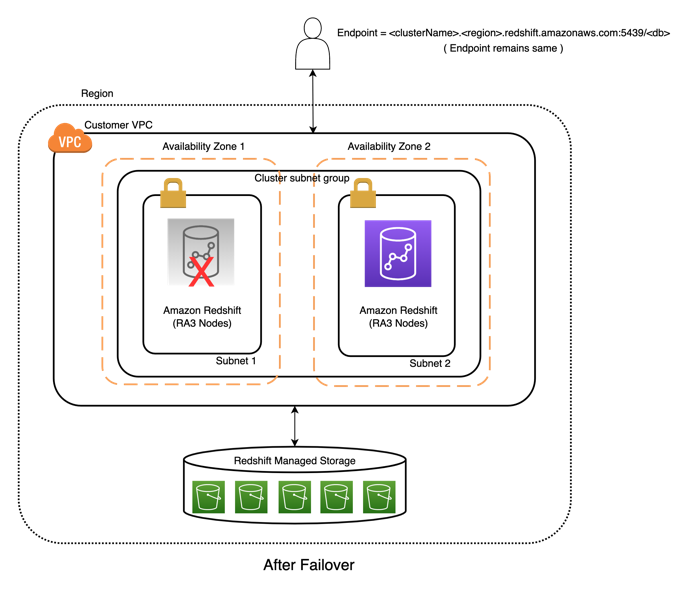
When the cluster relocation feature is enabled on an RA3 cluster, Amazon Redshift automatically relocates the cluster in situations where issues at the Availability Zone level prevent optimal cluster operation, or in case of large-scale failures impacting cluster resources in a data center within an Availability Zone. Relocation is done by creating the cluster’s compute resources in another Availability Zone. After a cluster is relocated to another Availability Zone, there is no loss of data and no application changes are required because the cluster endpoint doesn’t change. This provides a resilient architecture to maintain application availability. When a failover is initiated, the actual time to recover is dependent on the size of a cluster, with the average time under 15 minutes. Note that the ability to relocate is subject to capacity availability. Cluster relocation is offered at no charge.

The cluster relocation feature also helps you build a demonstratable Availability Zone recovery plan as well as address capacity shortages while expanding resources in a given Availability Zone. You can manually move the cluster to another Availability Zone to test your disaster recovery plan. In cases where a cluster can’t be resized or resumed due to capacity shortages in an Availability Zone, you can relocate the cluster to an Availability Zone with more capacity. If the relocation isn’t successful, the existing cluster is left unchanged. The existing cluster isn’t removed until the new cluster is successfully created as part of this process.

Solution overview

Amazon Redshift customers with operationally sensitive applications require application resiliency in the event of an outage in an Availability Zone. The Amazon Redshift relocation feature provides application resiliency through an easy-to-use architecture with zero loss of data and no application modifications.

The following diagram illustrates the architecture before failover

After failover, we have the following architecture

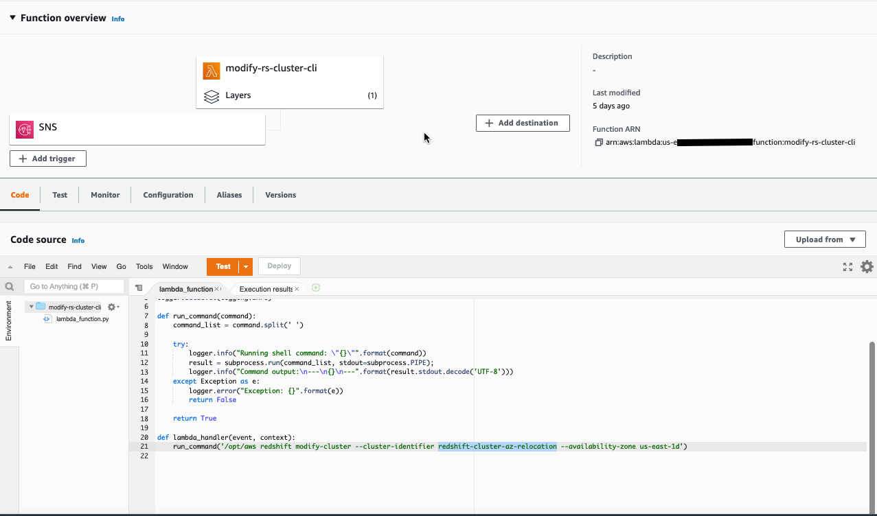
In this post, we demonstrate how to enable cluster relocation using either the AWS Management Console or AWS Command Line Interface (AWS CLI). We walk through examples of automatic and manual relocation, also show how to create a custom relocation solution using additional AWS services.

Prerequisites

Make sure you have the following prerequisites:

  • An AWS account.
  • Amazon Redshift clusters created in a VPC with a minimum of two subnets each in different Availability Zone.
  • An Amazon Redshift cluster with multiple Availability Zones configured in the cluster subnet group. You can set one up using the following AWS CloudFormation template.
  • The relocation feature is possible only with the RA3 Amazon Redshift node type.
  • In the Network and security settings section, choose Disable for the Publicly accessible option.

Enable cluster relocation

The first step is to enable cluster relocation, either via the console or AWS CLI. For more information, see Managing cluster relocation in Amazon Redshift. When using cluster relocation, be aware of the limitations.

Enable cluster relocation using the console

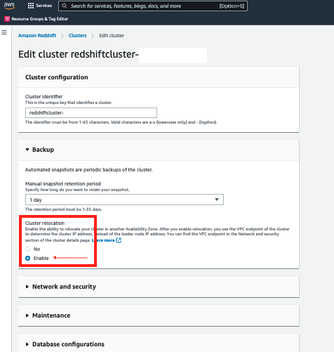
To enable cluster relocation on the console, complete the following steps:

  1. On the Amazon Redshift console, choose Clusters.
  2. Edit your cluster.
  3. Under Backup, for Cluster relocation, select Enable.

Enable cluster relocation using the AWS CLI

The relocation feature requires port 5439. If your current cluster is using a different port, you must modify it to use 5439 before modifying it to enable relocation. The following command modifies the port in case your cluster doesn’t use 5439:

aws redshift modify-cluster --cluster-identifier mycluster --port 5439

The following command enables the availability-zone-relocation parameter on the Amazon Redshift cluster:

aws redshift modify-cluster --cluster-identifier mycluster --availability-zone-relocation

The following command disables the availability-zone-relocation parameter on the Amazon Redshift cluster:

aws redshift modify-cluster --cluster-identifier mycluster --no-availability-zone-relocation

Automatic Availability Zone relocation

When using relocation in Amazon Redshift, you enable Amazon Redshift to move a cluster to another Availability Zone without any loss of data or changes to your applications. With relocation, you can resume operations when there is an interruption of service on your cluster with minimal impact. The new cluster will have the same endpoint so that applications can continue operations without modification.

This feature doesn’t require any action from the user besides the one-time configuration to enable the relocation feature. When the recovery feature is activated, the destination Availability Zone used is defined in the cluster subnet group.

Manual Availability Zone relocation

You can trigger the relocation manually, relocating a cluster to another Availability Zone. Complete the following steps:

  1. On the Amazon Redshift console, choose Clusters in the navigation pane.The clusters for your account in the current Region are listed. A subset of properties of each cluster is displayed in columns in the list.
  2. Choose the cluster you want to relocate.
  3. On the Actions menu, choose Relocate.If the Relocate option is greyed out, that indicates the cluster isn’t configured to use the Availability Zone relocation feature, or the cluster doesn’t meet the requirements for the relocation feature. For more details, refer to Limitations.
  4. In the Relocate cluster section, for Subnet group, choose an Availability Zone.The Availability Zone list is derived from the cluster subnet group. If you don’t choose an Availability Zone, Amazon Redshift chooses one for you.
  5. Choose Relocate.

After relocation is initiated, Amazon Redshift starts the relocation and displays the cluster status as Relocating. When the relocation complete, the cluster status changes to Available.

The following screenshot confirms the cluster has relocated to the correct Availability Zone.

Custom Availability Zone relocation solution

In this section, we simulate an automatic cluster failover to another Availability Zone with a reboot. Our event-based relocation solution involves setting up an alarm with an Amazon Simple Notification Service (Amazon SNS) topic, and creating an AWS Lambda function to trigger the relocation.

Create an alarm

To set up the alarm, complete the following steps:

  1. On the Amazon Redshift console, choose Clusters in the navigation pane.
  2. Choose your cluster.
  3. On the Cluster performance tab, expand the Alarms section and choose Create alarm.
  4. Configure the alarm for the HealthStatus metric and provide an alarm name and description.
  5. In the Alarm actions section, for Notifications¸ select Enabled.
  6. For Notify SNS topic, choose an existing SNS topic or create a new one.This topic receives a notification if the leader node isn’t healthy or is unavailable.
  7. Choose Create alarm.

Create a Lambda function

To set up a Lambda function to trigger Availability Zone relocation in case of cluster failure, complete the following steps:

  1. On the Lambda console, in the navigation pane, choose Functions.
  2. Open the Lambda function created by the CloudFormation stack.
  3. Edit the function code and modify the following snippet, updating the cluster ID and the destination Availability Zone:
    run_command('/opt/aws redshift modify-cluster --cluster-identifier redshift-cluster-az-relocation --availability-zone us-east-1d')

  4. Choose Add trigger.
  5. Under Trigger configuration, choose SNS.
  6. For SNS topic, choose the topic you specified for your alarm.
  7. Choose Add.

Test the Availability Zone relocation feature

Now we can test our custom Availability Zone relocation solution.

  1. On the Amazon Redshift console, choose Clusters in the navigation pane.
  2. Choose the cluster that you want to relocate.
  3. On the cluster detail page, note the cluster identifier.
  4. Use AWS CloudShell to run the following AWS CLI command to find the current Availability Zone of the Amazon Redshift cluster:
    aws redshift describe-clusters --cluster-identifier redshift-cluster-az-relocation

  5. From the JSON output, look for the attribute AvailabilityZone.
  6. On the cluster detail page, on the Actions menu, choose Reboot.
  7. Choose Reboot cluster.
    This triggers the alarm, and changes the alarm state to ALARM.
    Amazon SNS receives a message and triggers the Lambda function to perform the cluster relocation to the Availability Zone configured in the code. The cluster relocation takes several minutes.
  8. In CloudShell, run the following AWS CLI command to find the modified Availability Zone of the cluster:
    aws redshift describe-clusters --cluster-identifier redshift-cluster-az-relocation

Benefits

The cluster relocation feature provides the following benefits:

  • You can recover your cluster to another Availability Zone where failover can be done in minutes to ensure business continuity and high availability (HA). In addition, Availability Zones are physically separated resources that allow you to create a configuration for HA.
  • Amazon Redshift cluster recovery is a one-step process that may also be automated, as opposed to the manual process required to restore a cluster from a snapshot.
  • Because Amazon Redshift managed storage already includes the ability to replicate to two other Availability Zones using Amazon Simple Storage Service (Amazon S3), the cost of the additional copies is covered. There are no additional charges to use this feature.
  • The cluster relocation capability allows you to support business-critical use cases on your data warehouse requiring HA capabilities. This reduces the chance of an outage impacting your business operations.
  • You can benefit from automatic recovery to a failover Availability Zone when there are issues in optimal performance.
  • Relocation is provided free of charge and is subject to capacity availability.

Conclusion

In this post, we walked you through how the automated Availability Zone recovery feature in Amazon Redshift helps you build a resilient modern data architecture. The post also described how to perform a manual relocation through the AWS management console. Lastly, we discussed how to implement an event-based relocation using Amazon SNS and Lambda. These various techniques can help you plan your failover strategies based on your business needs.


About the authors

Kevin Burandt is a Senior Manager, Solutions Architecture at AWS. He is passionate about building and leading technical teams that  help customers and partners use technology to achieve business outcomes and deliver value to their customers. Outside of work, he enjoys home renovation projects and working on classic cars.

Indira Balakrishnan is a Principal Solutions Architect in the AWS Analytics Specialist SA Team. She is passionate about helping customers build cloud-based analytics solutions to solve their business problems using data-driven decisions. Outside of work, she volunteers at her kids’ activities and spends time with her family.

Ramkumar Nottath is a Sr. Solutions Architect at AWS focusing on Analytics services. He enjoys working with various customers to help them build scalable, reliable big data and analytics solutions. His interests extend to various technologies such as analytics, data warehousing, streaming, and machine learning. He loves spending time with his family and friends.

Tahir Aziz is an Analytics Solution Architect at AWS. He has worked with building data warehouses and big data solutions for over 13 years. He loves to help customers design end-to-end analytics solutions on AWS. Outside of work, he enjoys traveling and cooking.

Manage data transformations with dbt in Amazon Redshift

Post Syndicated from Randy Chng original https://aws.amazon.com/blogs/big-data/manage-data-transformations-with-dbt-in-amazon-redshift/

Amazon Redshift is a fully managed, petabyte-scale data warehouse service in the cloud. You can start with just a few hundred gigabytes of data and scale to a petabyte or more. Amazon Redshift enables you to use your data to acquire new insights for your business and customers while keeping costs low.

Together with price-performance, customers want to manage data transformations (SQL Select statements written by data engineers, data analysts, and data scientists) in Amazon Redshift with features including modular programming and data lineage documentation.

dbt (data build tool) is a framework that supports these features and more to manage data transformations in Amazon Redshift. There are two interfaces for dbt:

  • dbt CLI – Available as an open-source project
  • dbt Cloud – A hosted service with added features including an IDE, job scheduling, and more

In this post, we demonstrate some features in dbt that help you manage data transformations in Amazon Redshift. We also provide the dbt CLI and Amazon Redshift workshop to get started using these features.

Manage common logic

dbt enables you to write SQL in a modular fashion. This improves maintainability and productivity because common logic can be consolidated (maintain a single instance of logic) and referenced (build on existing logic instead of starting from scratch).

The following figure is an example showing how dbt consolidates common logic. In this example, two models rely on the same subquery. Instead of replicating the subquery, dbt allows you to create a model for the subquery and reference it later.

Manage common subquery in dbt

Figure 1: Manage common subquery in dbt

The concept of referencing isn’t limited to logic related to subqueries. You can also use referencing for logic related to fields.

The following is an example showing how dbt consolidates common logic related to fields. In this example, a model applies the same case statement on two fields. Instead of replicating the case statement for each field, dbt allows you to create a macro containing the case statement and reference it later.

Manage common case statement in dbt

Figure 2: Manage common case statement in dbt

How is a model in dbt subsequently created in Amazon Redshift? dbt provides you with the command dbt run, which materializes models as views or tables in your targeted Amazon Redshift cluster. You can try this out in the dbt CLI and Amazon Redshift workshop.

Manage common data mappings

Although you can use macros to manage data mappings (for example, mapping “1” to “One” and “2” to “Two”), an alternative is to maintain data mappings in files and manage the files in dbt.

The following is an example of how dbt manages common data mappings. In this example, a model applies one-to-one data mappings on a field. Instead of creating a macro for the one-to-one data mappings, dbt allows you to create a seed for the one-to-one data mappings in the form of a CSV file and then reference it later.

Manage common data mapping in dbt

Figure 3: Manage common data mapping in dbt

You can create or update a seed with a two-step process. After you create or update a CSV seed file, run the command dbt seed to create the CSV seed as a table in your targeted Amazon Redshift cluster before referencing it.

Manage data lineage documentation

After you have created models and seeds in dbt, and used dbt’s referencing capability, dbt provides you with a method to generate documentation on your data transformations.

You can run the command dbt docs generate followed by dbt docs serve to launch a locally hosted website containing documentation on your dbt project. When you choose a model on the locally hosted website, information about the model is displayed, including columns in the final view or table, dependencies to create the model, and the SQL that is compiled to create the view or table. The following screenshot shows an example of this documentation.

Documentation generated by dbt

Figure 4: Documentation generated by dbt

You can also visualize dependencies for improved navigation of documentations during impact analysis. In the following example graph, we can see that model rpt_tech_all_users is built referencing the model base_public_users, which in turn references the table users in the public schema.

Data lineage visualization generated by dbt

Figure 5: Data lineage visualization generated by dbt

Conclusion

This post covered how you can use dbt to manage data transformations in Amazon Redshift. As you explore dbt, you will come across other features like hooks, which you can use to manage administrative tasks, for example, continuous granting of privileges.

For a hands-on experience with dbt CLI and Amazon Redshift, we have a workshop with step-by-step instructions to help you create your first dbt project and explore the features mentioned in this post—models, macros, seeds, and hooks. Visit dbt CLI and Amazon Redshift to get started.

If you have any questions or suggestions, leave your feedback in the comments section. If you need any further assistance to optimize your Amazon Redshift implementation, contact your AWS account team or a trusted AWS partner.


About the authors

Randy Chng is an Analytics Acceleration Lab Solutions Architect at Amazon Web Services. He works with customers to accelerate their Amazon Redshift journey by delivering proof of concepts on key business problems.

Sean Beath is an Analytics Acceleration Lab Solutions Architect at Amazon Web Services. He delivers proof of concepts with customers on Amazon Redshift, helping customers drive analytics value on AWS.

Develop an Amazon Redshift ETL serverless framework using RSQL, AWS Batch, and AWS Step Functions

Post Syndicated from Lukasz Budnik original https://aws.amazon.com/blogs/big-data/develop-an-amazon-redshift-etl-serverless-framework-using-rsql-aws-batch-and-aws-step-functions/

Amazon Redshift RSQL is a command-line client for interacting with Amazon Redshift clusters and databases. You can connect to an Amazon Redshift cluster, describe database objects, query data, and view query results in various output formats. You can use enhanced control flow commands to replace existing extract, transform, load (ETL) and automation scripts.

This post explains how you can create a fully serverless and cost-effective Amazon Redshift ETL orchestration framework. To achieve this, you can use Amazon Redshift RSQL and AWS services such as AWS Batch and AWS Step Functions.

Overview of solution

When you’re migrating from existing data warehouses to Amazon Redshift, your existing ETL processes are implemented as proprietary scripts. These scripts contain SQL statements and complex business logic such as if-then-else control flow logic, error reporting, and error handling. You can convert all these features to Amazon Redshift RSQL, which you can use to replace existing ETL and other automation scripts. To learn more about Amazon Redshift RSQL features, examples, and use cases, see Accelerate your data warehouse migration to Amazon Redshift – Part 4.

AWS Schema Conversion Tool (AWS SCT) can convert proprietary scripts to Amazon Redshift RSQL. AWS SCT can automatically convert Teradata BTEQ scripts to Amazon Redshift RSQL. To learn more how to use AWS SCT, see Converting Teradata BTEQ scripts to Amazon Redshift RSQL with AWS SCT.

The goal of the solution presented in this post is to run complex ETL jobs implemented in Amazon Redshift RSQL scripts in the AWS Cloud without having to manage any infrastructure. In addition to meeting functional requirements, this solution also provides full auditing and traceability of all ETL processes that you run.

The following diagram shows the final architecture.

The deployment is fully automated using AWS Cloud Development Kit (AWS CDK) and comprises of the following stacks:

  • EcrRepositoryStack – Creates a private Amazon Elastic Container Registry (Amazon ECR) repository that hosts our Docker image with Amazon Redshift RSQL
  • RsqlDockerImageStack – Builds our Docker image asset and uploads it to the ECR repository
  • VpcStack – Creates a VPC with isolated subnets, creates an Amazon Simple Storage Service (Amazon S3) VPC endpoint gateway, as well as Amazon ECR, Amazon Redshift, and Amazon CloudWatch VPC endpoint interfaces
  • RedshiftStack – Creates an Amazon Redshift cluster, enables encryption, enforces encryption in-transit, enables auditing, and deploys the Amazon Redshift cluster in isolated subnets
  • BatchStack – Creates a compute environment (using AWS Fargate), job queue, and job definition (using our Docker image with RSQL)
  • S3Stack – Creates data, scripts, and logging buckets; enables encryption at-rest; enforces secure transfer; enables object versioning; and disables public access
  • SnsStack – Creates an Amazon Simple Notification Service (Amazon SNS) topic and email subscription (email is passed as a parameter)
  • StepFunctionsStack – Creates a state machine to orchestrate serverless RSQL ETL jobs
  • SampleDataDeploymentStack – Deploys sample RSQL ETL scripts and sample TPC benchmark datasets

Prerequisites

You should have the following prerequisites:

Deploy AWS CDK stacks

To deploy the serverless RSQL ETL framework solution, use the following code. Replace 123456789012 with your AWS account number, eu-west-1 with the AWS Region to which you want deploy the solution, and [email protected] with your email address to which ETL success and failure notifications are sent.

git clone https://github.com/aws-samples/amazon-redshift-serverless-rsql-etl-framework
cd amazon-redshift-serverless-rsql-etl-framework
npm install
./cdk.sh 123456789012 eu-west-1 bootstrap
./cdk.sh 123456789012 eu-west-1 deploy --all --parameters SnsStack:EmailAddressSubscription=[email protected]

The whole process takes a few minutes. While AWS CDK creates all the stacks, you can continue reading this post.

Create the RSQL container image

AWS CDK creates an RSQL Docker image. This Docker image is the basic building block of our solution. All ETL processes run inside it. AWS CDK creates the Docker image locally using Docker Engine and then uploads it to the Amazon ECR repository.

The Docker image is based on an Amazon Linux 2 Docker image. It has the following tools installed: the AWS Command Line Interface (AWS CLI), unixODBC, Amazon Redshift ODBC driver, and Amazon Redshift RSQL. It also contains .odbc.ini file, which defines the etl profile, which is used to connect to the Amazon Redshift cluster. See the following code:

FROM amazonlinux:2

ENV AMAZON_REDSHIFT_ODBC_VERSION=1.4.52.1000
ENV AMAZON_REDSHIFT_RSQL_VERSION=1.0.4

RUN yum install -y openssl gettext unixODBC awscli && \
yum clean all

RUN rpm -i \
https://s3.amazonaws.com/redshift-downloads/drivers/odbc/${AMAZON_REDSHIFT_ODBC_VERSION}/AmazonRedshiftODBC-64-bit-${AMAZON_REDSHIFT_ODBC_VERSION}-1.x86_64.rpm \
https://s3.amazonaws.com/redshift-downloads/amazon-redshift-rsql/${AMAZON_REDSHIFT_RSQL_VERSION}/AmazonRedshiftRsql-${AMAZON_REDSHIFT_RSQL_VERSION}-1.x86_64.rpm

COPY .odbc.ini .odbc.ini
COPY fetch_and_run.sh /usr/local/bin/fetch_and_run.sh

ENV ODBCINI=.odbc.ini
ENV ODBCSYSINI=/opt/amazon/redshiftodbc/Setup
ENV AMAZONREDSHIFTODBCINI=/opt/amazon/redshiftodbc/lib/64/amazon.redshiftodbc.ini

ENTRYPOINT ["/usr/local/bin/fetch_and_run.sh"]

The following code example shows the .odbc.ini file. It defines an etl profile, which uses an AWS Identity and Access Management (IAM) role to get temporary cluster credentials to connect to Amazon Redshift. AWS CDK creates this role for us. Because of this, we don’t need to hard-code credentials in a Docker image. The Database, DbUser, and ClusterID parameters are set in AWS CDK. Also, AWS CDK replaces the Region parameter at runtime with the Region to which you deploy the stacks.

[ODBC]
Trace=no

[etl]
Driver=/opt/amazon/redshiftodbc/lib/64/libamazonredshiftodbc64.so
Database=demo
DbUser=etl
ClusterID=redshiftblogdemo
Region=eu-west-1
IAM=1

For more information about connecting to Amazon Redshift clusters with RSQL, see Connect to a cluster with Amazon Redshift RSQL.

Our Docker image implements a well-known fetch and run integration pattern. To learn more about this pattern, see Creating a Simple “Fetch & Run” AWS Batch Job. The Docker image fetches the ETL script from an external repository, and then runs it. AWS CDK passes the information about the ETL script to run to the Docker container at runtime as an AWS Batch job parameter. The job parameter is exposed to the container as an environment variable called BATCH_SCRIPT_LOCATION. Our job also expects two other environment variables: DATA_BUCKET_NAME, which is the name of the S3 data bucket, and COPY_IAM_ROLE_ARN, which is the Amazon Redshift IAM role used for the COPY command to load the data into Amazon Redshift. All environment variables are set automatically by AWS CDK. The fetch_and_run.sh script is the entry point of the Docker container. See the following code:

#!/bin/bash

# This script expects the following env variables to be set:
# BATCH_SCRIPT_LOCATION - full S3 path to RSQL script to run
# DATA_BUCKET_NAME - S3 bucket name with the data
# COPY_IAM_ROLE_ARN - IAM role ARN that will be used to copy the data from S3 to Redshift

PATH="/bin:/usr/bin:/sbin:/usr/sbin:/usr/local/bin:/usr/local/sbin"

if [ -z "${BATCH_SCRIPT_LOCATION}" ] || [ -z "${DATA_BUCKET_NAME}" ] || [ -z "${COPY_IAM_ROLE_ARN}" ]; then
    echo "BATCH_SCRIPT_LOCATION/DATA_BUCKET_NAME/COPY_IAM_ROLE_ARN not set. No script to run."
    exit 1
fi

# download script to a temp file
TEMP_SCRIPT_FILE=$(mktemp)
aws s3 cp ${BATCH_SCRIPT_LOCATION} ${TEMP_SCRIPT_FILE}

# execute script
# envsubst will replace ${COPY_IAM_ROLE_ARN} and ${COPY_IAM_ROLE_ARN} placeholders with actual values
envsubst < ${TEMP_SCRIPT_FILE} | rsql -D etl

exit $?

Create AWS Batch resources

Next, AWS CDK creates the AWS Batch compute environment, job queue, and job definition. As a fully managed service, AWS Batch helps you run batch computing workloads of any scale. AWS CDK creates a Fargate serverless compute environment for us. The compute environment deploys inside the same VPC as the Amazon Redshift cluster, inside the isolated subnets. The job definition uses our Docker image with Amazon Redshift RSQL.

This step turns Amazon Redshift RSQL into a serverless service. You can build complex ETL workflows based on this generic job.

Create a Step Functions state machine

AWS CDK then moves to the deployment of the Step Functions state machine. Step Functions enables you to build complex workflows in a visual way directly in your browser. This service supports over 9,000 API actions from over 200 AWS services.

You can use Amazon States Language to create a state machine on the Step Functions console. The Amazon States Language is a JSON-based, structured language used to define your state machine. You can also build them programmatically using AWS CDK, as I have done for this post.

After AWS CDK finishes, a new state machine is created in your account called ServerlessRSQLETLFramework. To run it, complete the following steps:

  1. Navigate to the Step Functions console.
  2. Choose the function to open the details page.
  3. Choose Edit, and then choose Workflow Studio New.
    The following screenshot shows our state machine.
  4. Choose Cancel to leave Workflow Studio, then choose Cancel again to leave the edit mode.
    You will be brought back to the details page.
  5. Choose Start execution.
    A dialog box appears. By default, the Name parameter is set to a random identifier, and the Input parameter is set to a sample JSON document.
  6. Delete the Input parameter and choose Start execution to start the state machine.

The Graph view on the details page updates in real time. The state machine starts with a parallel state with two branches. In the left branch, the first job loads customer data into staging table, then the second job merges new and existing customer records. In the right branch, two smaller tables for regions and nations are loaded and then merged one after another. The parallel state waits until all branches are complete before moving to the vacuum-analyze state, which runs VACUUM and ANALYZE commands on Amazon Redshift. The sample state machine also implements the Amazon SNS Publish API actions to send notifications about success or failure.

From the Graph view, you can check the status of each state by choosing it. Every state that uses an external resource has a link to it on the Details tab. In our example, next to every AWS Batch Job state, you can see a link to the AWS Batch Job details page. Here, you can view the status, runtime, parameters, IAM roles, link to Amazon CloudWatch Logs with the logs produced by ETL scripts, and more.

Clean up

To avoid ongoing charges for the resources that you created, delete them. AWS CDK deletes all resources except data resources such as S3 buckets and Amazon ECR repositories.

  1. First, delete all AWS CDK stacks. In the following code, provide your own AWS account and AWS Region:
    ./cdk.sh 123456789012 eu-west-1 destroy --all

  2. On the Amazon S3 console, empty and delete buckets with names starting with:
    1. s3stack-rsqletldemodata
    2. s3stack-rsqletldemoscripts
    3. s3stack-rsqletldemologging
  3. Finally, on the Amazon ECR console, delete repositories with names starting with:
    1. ecrrepositorystack-amazonlinuxrsql
    2. cdk-container-assets

Next steps

Here are some ideas of additional enhancements that you can add to the described solution.

You can break large complex state machines into smaller building blocks by creating self-contained state machines. In our example, you could create state machines for every pair of copy and merge jobs. You could create three such state machines: Copy and Merge Customer, Copy and Merge Region, and Copy and Merge Nation, and then call them from the main state machine. For complex workflows, a different team can work on each sub-state machine in parallel. Also, this pattern promotes reuse of existing components, best practices, and security mechanisms.

You can use Amazon S3 Object Functions or Amazon S3 EventBridge notifications to start a state machine automatically after you upload a file to an S3 bucket. To learn more about Amazon S3 integration with Amazon EventBridge, see Use Amazon S3 Event Notifications with Amazon EventBridge. This way you can achieve a fully event-driven serverless ETL orchestration framework.

Summary

You can use Amazon Redshift RSQL, AWS Batch, and Step Functions to create modern, serverless, and cost-effective ETL workflows. There is no infrastructure to manage, and Amazon Redshift RSQL works as a serverless RSQL service. In this post, we demonstrated how to use this serverless RSQL service to build more complex ETL workflows with Step Functions.

Step Functions integrates natively with over 200 AWS services. This opens a new world of possibilities to AWS customers and partners, who can integrate their processes with other data, analytics, machine learning, and compute services such as Amazon S3, Amazon DynamoDB, AWS Glue, Amazon OpenSearch Service (successor to Amazon Elasticsearch Service), Amazon SageMaker, AWS Lambda, and more. The additional advantage of Step Functions and AWS Batch is that you have full traceability and auditing out of the box. Step Functions shows Graph or Event views together with a complete history for all state machine runs.

In this post, I used RSQL automation scripts as the building blocks of ETL workflows. Using RSQL is a common integration pattern that we see for customers migrating from Teradata BTEQ scripts. However, if you have simple ETL or ELT processes that can be written as plain SQL, you can invoke the Amazon Redshift Data API directly from Step Functions. To learn more about this integration pattern, see ETL orchestration using the Amazon Redshift Data API and AWS Step Functions with AWS SDK integration.


About the author

Lukasz is a Principal Software Dev Engineer working in the AWS DMA team. Lukasz helps customers move their workloads to AWS and specializes in migrating data warehouses and data lakes to AWS. In his free time, Lukasz enjoys learning new human languages.

How Epos Now modernized their data platform by building an end-to-end data lake with the AWS Data Lab

Post Syndicated from Debadatta Mohapatra original https://aws.amazon.com/blogs/big-data/how-epos-now-modernized-their-data-platform-by-building-an-end-to-end-data-lake-with-the-aws-data-lab/

Epos Now provides point of sale and payment solutions to over 40,000 hospitality and retailers across 71 countries. Their mission is to help businesses of all sizes reach their full potential through the power of cloud technology, with solutions that are affordable, efficient, and accessible. Their solutions allow businesses to leverage actionable insights, manage their business from anywhere, and reach customers both in-store and online.

Epos Now currently provides real-time and near-real-time reports and dashboards to their merchants on top of their operational database (Microsoft SQL Server). With a growing customer base and new data needs, the team started to see some issues in the current platform.

First, they observed performance degradation for serving the reporting requirements from the same OLTP database with the current data model. A few metrics that needed to be delivered in real time (seconds after a transaction was complete) and a few metrics that needed to be reflected in the dashboard in near-real-time (minutes) took several attempts to load in the dashboard.

This started to cause operational issues for their merchants. The end consumers of reports couldn’t access the dashboard in a timely manner.

Cost and scalability also became a major problem because one single database instance was trying to serve many different use cases.

Epos Now needed a strategic solution to address these issues. Additionally, they didn’t have a dedicated data platform for doing machine learning and advanced analytics use cases, so they decided on two parallel strategies to resolve their data problems and better serve merchants:

  • The first was to rearchitect the near-real-time reporting feature by moving it to a dedicated Amazon Aurora PostgreSQL-Compatible Edition database, with a specific reporting data model to serve to end consumers. This will improve performance, uptime, and cost.
  • The second was to build out a new data platform for reporting, dashboards, and advanced analytics. This will enable use cases for internal data analysts and data scientists to experiment and create multiple data products, ultimately exposing these insights to end customers.

In this post, we discuss how Epos Now designed the overall solution with support from the AWS Data Lab. Having developed a strong strategic relationship with AWS over the last 3 years, Epos Now opted to take advantage of the AWS Data lab program to speed up the process of building a reliable, performant, and cost-effective data platform. The AWS Data Lab program offers accelerated, joint-engineering engagements between customers and AWS technical resources to create tangible deliverables that accelerate data and analytics modernization initiatives.

Working with an AWS Data Lab Architect, Epos Now commenced weekly cadence calls to come up with a high-level architecture. After the objective, success criteria, and stretch goals were clearly defined, the final step was to draft a detailed task list for the upcoming 3-day build phase.

Overview of solution

As part of the 3-day build exercise, Epos Now built the following solution with the ongoing support of their AWS Data Lab Architect.

Epos Now Arch Image

The platform consists of an end-to-end data pipeline with three main components:

  • Data lake – As a central source of truth
  • Data warehouse – For analytics and reporting needs
  • Fast access layer – To serve near-real-time reports to merchants

We chose three different storage solutions:

  • Amazon Simple Storage Service (Amazon S3) for raw data landing and a curated data layer to build the foundation of the data lake
  • Amazon Redshift to create a federated data warehouse with conformed dimensions and star schemas for consumption by Microsoft Power BI, running on AWS
  • Aurora PostgreSQL to store all the data for near-real-time reporting as a fast access layer

In the following sections, we go into each component and supporting services in more detail.

Data lake

The first component of the data pipeline involved ingesting the data from an Amazon Managed Streaming for Apache Kafka (Amazon MSK) topic using Amazon MSK Connect to land the data into an S3 bucket (landing zone). The Epos Now team used the Confluent Amazon S3 sink connector to sink the data to Amazon S3. To make the sink process more resilient, Epos Now added the required configuration for dead-letter queues to redirect the bad messages to another topic. The following code is a sample configuration for a dead-letter queue in Amazon MSK Connect:

Because Epos Now was ingesting from multiple data sources, they used Airbyte to transfer the data to a landing zone in batches. A subsequent AWS Glue job reads the data from the landing bucket , performs data transformation, and moves the data to a curated zone of Amazon S3 in optimal format and layout. This curated layer then became the source of truth for all other use cases. Then Epos Now used an AWS Glue crawler to update the AWS Glue Data Catalog. This was augmented by the use of Amazon Athena for doing data analysis. To optimize for cost, Epos Now defined an optimal data retention policy on different layers of the data lake to save money as well as keep the dataset relevant.

Data warehouse

After the data lake foundation was established, Epos Now used a subsequent AWS Glue job to load the data from the S3 curated layer to Amazon Redshift. We used Amazon Redshift to make the data queryable in both Amazon Redshift (internal tables) and Amazon Redshift Spectrum. The team then used dbt as an extract, load, and transform (ELT) engine to create the target data model and store it in target tables and views for internal business intelligence reporting. The Epos Now team wanted to use their SQL knowledge to do all ELT operations in Amazon Redshift, so they chose dbt to perform all the joins, aggregations, and other transformations after the data was loaded into the staging tables in Amazon Redshift. Epos Now is currently using Power BI for reporting, which was migrated to the AWS Cloud and connected to Amazon Redshift clusters running inside Epos Now’s VPC.

Fast access layer

To build the fast access layer to deliver the metrics to Epos Now’s retail and hospitality merchants in near-real time, we decided to create a separate pipeline. This required developing a microservice running a Kafka consumer job to subscribe to the same Kafka topic in an Amazon Elastic Kubernetes Service (Amazon EKS) cluster. The microservice received the messages, conducted the transformations, and wrote the data to a target data model hosted on Aurora PostgreSQL. This data was delivered to the UI layer through an API also hosted on Amazon EKS, exposed through Amazon API Gateway.

Outcome

The Epos Now team is currently building both the fast access layer and a centralized lakehouse architecture-based data platform on Amazon S3 and Amazon Redshift for advanced analytics use cases. The new data platform is best positioned to address scalability issues and support new use cases. The Epos Now team has also started offloading some of the real-time reporting requirements to the new target data model hosted in Aurora. The team has a clear strategy around the choice of different storage solutions for the right access patterns: Amazon S3 stores all the raw data, and Aurora hosts all the metrics to serve real-time and near-real-time reporting requirements. The Epos Now team will also enhance the overall solution by applying data retention policies in different layers of the data platform. This will address the platform cost without losing any historical datasets. The data model and structure (data partitioning, columnar file format) we designed greatly improved query performance and overall platform stability.

Conclusion

Epos Now revolutionized their data analytics capabilities, taking advantage of the breadth and depth of the AWS Cloud. They’re now able to serve insights to internal business users, and scale their data platform in a reliable, performant, and cost-effective manner.

The AWS Data Lab engagement enabled Epos Now to move from idea to proof of concept in 3 days using several previously unfamiliar AWS analytics services, including AWS Glue, Amazon MSK, Amazon Redshift, and Amazon API Gateway.

Epos Now is currently in the process of implementing the full data lake architecture, with a rollout to customers planned for late 2022. Once live, they will deliver on their strategic goal to provide real-time transactional data and put insights directly in the hands of their merchants.


About the Authors

Jason Downing is VP of Data and Insights at Epos Now. He is responsible for the Epos Now data platform and product direction. He specializes in product management across a range of industries, including POS systems, mobile money, payments, and eWallets.

Debadatta Mohapatra is an AWS Data Lab Architect. He has extensive experience across big data, data science, and IoT, across consulting and industrials. He is an advocate of cloud-native data platforms and the value they can drive for customers across industries.

Use SQL queries to define Amazon Redshift datasets in AWS Glue DataBrew

Post Syndicated from Suraj Shivananda original https://aws.amazon.com/blogs/big-data/use-sql-queries-to-define-amazon-redshift-datasets-in-aws-glue-databrew/

In the post Data preparation using Amazon Redshift with AWS Glue DataBrew, we saw how to create an AWS Glue DataBrew job using a JDBC connection for Amazon Redshift. In this post, we show you how to create a DataBrew profile job and a recipe job using an Amazon Redshift connection with custom SQL.

DataBrew is a visual data preparation tool that can help you simplify your extract, transform, and load (ETL) process. You can now define a dataset from Amazon Redshift by applying custom SQL statements. Applying a custom SQL statement to a large source table allows you to select, join, and filter the data before cleaning, normalizing, and transforming it in a DataBrew project. Filtering and joining the data from your data source and only bringing in the data you want to transform simplifies the ETL process.

In this post, we demonstrate how to use custom SQL queries to define your Amazon Redshift datasets in DataBrew.

Solution overview

To implement this solution, you complete the following high-level steps:

  1. Create an Amazon Redshift connection.
  2. Create your dataset and use SQL queries to define your Amazon Redshift source datasets.
  3. Create a DataBrew profile job to profile the source data.
  4. Create a DataBrew project and recipe job to transform the data and load it to Amazon Simple Storage Service (Amazon S3).

The following diagram illustrates the architecture for our solution.

Prerequisites

To use this solution, complete the following prerequisite steps:

  1. Have an AWS account.
  2. Create an Amazon Redshift cluster in a private subnet within a VPC as a security best practice.
  3. Because DataBrew commands require that the cluster has access to Amazon S3, make sure you create a gateway VPC endpoint to Amazon S3. The gateway endpoint provides reliable connectivity to Amazon S3 without requiring an internet gateway or NAT device from your VPC.
  4. Enable the enhanced VPC routing in the Amazon Redshift cluster. Enhanced VPC routing forces all Amazon Redshift commands to use the connectivity to the gateway VPC endpoint to Amazon S3 in the same AWS Region as your cluster.
  5. Create a database and tables, and load the sample data in the Amazon Redshift cluster.
  6. Prepare a SQL query to extract the source dataset. You use this SQL query later in this post to create an Amazon Redshift source dataset in DataBrew.
  7. Create an S3 bucket to store data from the profile and recipe jobs. The DataBrew connection temporarily stores intermediate data in Amazon S3.
  8. For our use case, we use a mock dataset. You can download the DDL and data files from GitHub.

Security best practices

Consider the following best practices in order to mitigate security threats:

  • Review the shared responsibility model when using DataBrew.
  • Restrict network access for inbound and outbound traffic to least privilege. Take advantage of the routing traffic within the VPC by using an Amazon S3 gateway endpoint and enhanced VPC routing in Amazon Redshift.
  • Enable the lifecycle policy in Amazon S3 to retain only necessary data, and delete unnecessary data.
  • Enable Amazon S3 versioning and cross-Region replication for critical datasets to protect against accidental deletes.
  • Enable server-side encryption using AWS KMS (SSE-KMS) or Amazon S3 (SSE-S3).
  • DataBrew uses Amazon CloudWatch for logging, so you should update your log retention period to retain logs for the appropriate length of time.

Create an Amazon Redshift connection

In this section, you create a connection in DataBrew to connect to your Amazon Redshift cluster.

  1. On the DataBrew console, choose Datasets in the navigation pane.
  2. On the Connections tab, choose Create connection.
  3. For Connection name, enter a name, such as order-db-connection.
  4. For Connection type, select Amazon Redshift.
  5. Under Connection access, provide the Amazon Redshift cluster name, database name, database user, and database password.
  6. Choose Create connection.

Create your dataset by applying a custom SQL statement to filter the source data

In this section, you create a Amazon Redshift connection, add your custom SQL statement, and validate it. You can also validate your SQL statement directly in your Amazon Redshift cluster by using the Amazon Redshift query editor v2. The purpose of validating the SQL statement is to help you avoid failure in loading your dataset into a project or job. Also, checking the query runtime ensures that it runs in under 3 minutes, avoiding timeouts during project loading. To analyze and improve query performance in Amazon Redshift, see Tuning query performance.

  1. On the DataBrew console, choose Datasets in the navigation pane.
  2. On the Datasets tab, choose Connect new dataset.
  3. For Dataset name, enter a name, such as order-data.
  4. In the left pane, choose Amazon Redshift under Database connections.
  5. Add your Amazon Redshift connection and select Enter custom SQL.
  6. Enter the SQL query and choose Validate SQL.
  7. Under Additional configurations, for Enter S3 destination, provide an S3 destination to temporarily store the intermediate results.
  8. Choose Create dataset.

Create a DataBrew profile job

In this section, you use the newly created Amazon Redshift dataset to create a profile job. Data profiling helps you understand your dataset and plan the data preparation steps needed in running your recipe jobs.

  1. On the DataBrew console, choose Jobs in the navigation pane.
  2. On the Profile jobs tab, choose Create job.
  3. For Job name, enter a name, such as order-data-profile-job.
  4. For Job type¸ select Create a profile job.
  5. Under Job input, choose Browse datasets and choose the dataset you created earlier (order-data).
  6. For Data sample, select Full dataset.
  7. Under Job output settings¸ for S3 location, enter the S3 bucket for the job output files.
  8. For Role name, choose an AWS Identity and Access Management (IAM) role with permission for DataBrew to connect to the data on your behalf. For more information, refer to Adding an IAM role with data resource permissions.
  9. Choose Create and run job.

Check the status of your profile job. A profile output file is created and stored in Amazon S3 upon completion. You can choose View data profile to see more information.

In addition to an output file, DataBrew also provides visualizations. On the Dataset profile overview tab, you can see data visualizations that can help you understand your data better. Next, you can see detailed statistics about your data on the Column statistics tab, illustrated with graphics and charts. You can define data quality rules on the Data quality rules tab, and then see the results from the data quality ruleset that applies to this dataset.

For example, in the following screenshot, the amount column has 2% missing values, as shown on the Column statistics tab. You can provide rules that avoid triggering a recipe job in case of an anomaly. You can also notify the source teams to handle or acknowledge the missing values. DataBrew users can also add steps in the recipe job to handle the anomalies and missing values.

Create a DataBrew project and recipe job

In this section, you start analyzing and transforming your Amazon Redshift dataset in a DataBrew project. The custom SQL statement runs in Amazon Redshift when the project is loaded. Databrew performs read-only access to your source data.

Create a project

To create your project, complete the following steps:

  1. On the DataBrew console, choose Projects in the navigation pane.
  2. Choose Create project.
  3. For Project name, enter a name, such as order-data-proj.
  4. Under Recipe details¸ choose Create new recipe and enter a recipe name, such as order-data-proj-recipe.
  5. For Select a dataset, select My datasets.
  6. Select the dataset you created earlier (order-data).
  7. Under Permissions, for Role name, choose your DataBrew role.
  8. Choose Create project.

DataBrew starts a session, constructs a DataFrame, extracts sample data, infers basic statistics, and displays the sample data in a grid view. You can add steps to build a transformation recipe. As of this writing, DataBrew offers over 350 transformations, with more on the way.

For our example use case, Company ABC has set a target to ship all orders within 7 days after the order date (internal SLA). They want a list of orders that didn’t meet the 7-day SLA for additional investigation. The following sample recipe contains steps to handle the missing values, filter the values by amount, change the date format, calculate the date difference, and filter the values by shipping days. The detailed steps are as follows:

  1. Fill missing values with 0 for the amount column.
  2. Filter values by amount greater than 0.
  3. Change the format of order_timestamp to align with ship_date.
  4. Create a new column called days_for_shipping using the dateTime function DATEDIFF to show the difference between order_timestamp and ship_date in days.
  5. Filter the values by days_for_shipping greater than 7.

Create a recipe job

To create your DataBrew recipe job, complete the following steps:

  1. On the DataBrew console, choose Jobs in the navigation pane.
  2. Choose Create job.
  3. For Job name¸ enter a name, such as SHIPPING-SLA-MISS.
  4. Under Job output settings, configure your Amazon S3 output settings.
  5. For S3 location, enter the location of your output bucket.
  6. For Role name, choose the IAM role that contains permissions for DataBrew to connect on your behalf.
  7. Choose Create and run job.

You can check the status of your job on the Jobs page.

The output file is in Amazon S3 as specified, and your data transformation is now complete.

Clean up

To avoid incurring future charges, we recommend deleting the resources you created during this walkthrough.

Conclusion

In this post, we walked through applying custom SQL statements to an Amazon Redshift data source in your dataset, which you can use in profiling and transformation jobs. You can now focus on building your data transformation steps knowing that you’re working on only the needed data.

To learn more about the various supported data sources for DataBrew, see Connecting to data with AWS Glue DataBrew.


About the authors

Suraj Shivananda is a Solutions Architect at AWS. He has over a decade of experience in Software Engineering, Data and Analytics, DevOps specifically for data solutions, automating and optimizing cloud based solutions. He’s a trusted technical advisor and helps customers build Well Architected solutions on the AWS platform.

Marie Yap is a Principal Solutions Architect for Amazon Web Services based in Hawaii. In this role, she helps various organizations begin their journey to the cloud. She also specializes in analytics and modern data architectures.

Dhiraj Thakur is a Solutions Architect with Amazon Web Services. He works with AWS customers and partners to provide guidance on enterprise cloud adoption, migration, and strategy. He is passionate about technology and enjoys building and experimenting in the analytics and AI/ML space.

Accelerate your data warehouse migration to Amazon Redshift – Part 6

Post Syndicated from Michael Soo original https://aws.amazon.com/blogs/big-data/part-6-accelerate-your-data-warehouse-migration-to-amazon-redshift/

This is the sixth in a series of posts. We’re excited to share dozens of new features to automate your schema conversion; preserve your investment in existing scripts, reports, and applications; accelerate query performance; and potentially simplify your migrations from legacy data warehouses to Amazon Redshift.

Check out all the previous posts in this series:

Amazon Redshift is the cloud data warehouse of choice for tens of thousands of customers who use it to analyze exabytes of data to gain business insights. With Amazon Redshift, you can query data across your data warehouse, operational data stores, and data lake using standard SQL. You can also integrate other AWS services such as Amazon EMR, Amazon Athena, Amazon SageMaker, AWS Glue, AWS Lake Formation, and Amazon Kinesis to use all the analytic capabilities in the AWS Cloud.

Migrating a data warehouse can be a complex undertaking. Your legacy workload might rely on proprietary features that aren’t directly supported by a modern data warehouse like Amazon Redshift. For example, some data warehouses enforce primary key constraints, making a tradeoff with DML performance. Amazon Redshift lets you define a primary key but uses the constraint for query optimization purposes only. If you use Amazon Redshift, or are migrating to Amazon Redshift, you may need a mechanism to check that primary key constraints are not being violated by extract, transform, and load (ETL) processes.

In this post, we describe two design patterns that you can use to accomplish this efficiently. We also show you how to use the AWS Schema Conversion Tool (AWS SCT) to automatically apply the design patterns to your SQL code.

We start by defining the semantics to address. Then we describe the design patterns and analyze their performance. We conclude by showing you how AWS SCT can automatically convert your code to enforce primary keys.

Primary keys

A primary key (PK) is a set of attributes such that no two rows can have the same value in the PK. For example, the following Teradata table has a two-attribute primary key (emp_id, div_id). Presumably, employee IDs are unique only within divisions.

CREATE TABLE testschema.emp ( 
  emp_id INTEGER NOT NULL
, name VARCHAR(12) NOT NULL
, div_id INTEGER NOT NULL
, job_title VARCHAR(12)
, salary DECIMAL(8,2)
, birthdate DATE NOT NULL ) 
CONSTRAINT pk_emp_id PRIMARY KEY (emp_id, div_id);

Most databases require that a primary key satisfy two criteria:

  • Uniqueness – The PK values are unique over all rows in the table
  • Not NULL – The PK attributes don’t accept NULL values

In this post, we focus on how to support the preceding primary key semantics. We describe two design patterns that you can use to develop SQL applications that respect primary keys in Amazon Redshift. Our focus is on INSERT-SELECT statements. Customers have told us that INSERT-SELECT operations comprise over 50% of the DML workload against tables with unique constraints. We briefly provide some guidance for other DML statements later in the post.

INSERT-SELECT

In the rest of this post, we dive deep into design patterns for INSERT-SELECT statements. We’re concerned with statements of the following form:

INSERT INTO <target table> SELECT * FROM <staging table>

The schema of the staging table is identical to the target table on a column-by-column basis.

A duplicate PK value can be introduced by two scenarios:

  • The staging table contains duplicates, meaning there are two or more rows in the staging data with the same PK value
  • There is a row x in the staging table and a row y in the target table that share the same PK value

Note that these situations are independent. It can be the case that the staging table contains duplicates, the staging table and target table share a duplicate, or both.

It’s imperative that the staging table doesn’t contain duplicate PK values. To ensure this, you can apply deduplication logic, as described in this post, to the staging table when it’s loaded. Alternatively, if your upstream source can guarantee that duplicates have been eliminated before delivery, you can eliminate this step.

Join

The first design pattern simply joins the staging and target tables. If any rows are returned, then the staging and target tables share a primary key value.

Suppose we have staging and target tables defined as the following:

CREATE TABLE stg ( 
  pk_col INTEGER 
, payload VARCHAR(100) 
, PRIMARY KEY (pk_col)
); 

CREATE TABLE tgt ( 
  pk_col INTEGER 
, payload VARCHAR(100) 
, PRIMARY KEY (pk_col)
);
We can use the following query to detect any duplicate primary key values:
SELECT count(1) 
FROM stg, tgt 
WHERE tgt.pk_col = stg.pk_col;

If the primary key has multiple columns, then the WHERE condition can be extended:

SELECT count(1)
FROM stg, tgt
WHERE
    tgt.pk_col1 = stg.pk_col1
AND tgt.pk_col2 = tgt.pk_col2
AND …
;

There is one complication with this design pattern. If you allow NULL values in the primary key column, then you need to add special code to handle the NULL to NULL matching:

SELECT count(1)
FROM stg, tgt
WHERE
   (tgt.pk_col = stg.pk_col) 
OR (tgt.pk_col IS NULL AND stg.pk_col IS NULL)
;

This is the primary disadvantage of this design pattern—the code can be ugly and unintuitive. Furthermore, if you have a multicolumn primary key, then the code becomes even more complicated.

INTERSECT

The second design pattern that we describe uses the Amazon Redshift INTERSECT operation. INTERSECT is a set-based operation that determines if two queries have any rows in common. You can check out UNION, INTERSECT, and EXCEPT in the Amazon Redshift documentation for more information.

We can determine if the staging and target table have duplicate PK values using the following query:

SELECT COUNT(1)
FROM (
  SELECT pk_col FROM stg
  INTERSECT
  SELECT pk_col FROM tgt
) a
;

If the primary key is composed of more than one column, you can simply modify the subqueries to include the additional columns:

SELECT COUNT(1)
FROM (
  SELECT pk_col1, pk_col2, …, pk_coln FROM stg
  INTERSECT
  SELECT pk_col, pk_col2, …, pk_coln FROM tgt
) a
;

This pattern’s main advantage is its simplicity. The code is easier to understand and validate than the join design pattern. INTERSECT handles the NULL to NULL matching implicitly so you don’t have to write any special code for NULL values.

Performance

We tested both design patterns using an Amazon Redshift cluster consisting of 12 ra3.4xlarge nodes. Each node contained 12 CPU and 96 GB of memory.

We created the staging and target tables with the same distribution and sort keys to minimize data redistribution at query time.

We generated the test data artificially using a custom program. The target dataset contained 1 billion rows of data. We ran 10 trials of both algorithms using staging datasets that ranged from 20–200 million rows, in 20-million-row increments.

In the following graph, the join design pattern is shown as a blue line. The intersect design pattern is shown as an orange line.

You can observe that the performance of both algorithms is excellent. Each is able to detect duplicates in less than 1 second for all trials. The join algorithm outperforms the intersect algorithm, but both have excellent performance.

So, which algorithm should use you choose? If you’re developing a new application on Amazon Redshift, the intersect algorithm is probably the best choice. The inherent NULL matching logic and simple intuitive code make this the best choice for new applications.

Conversely, if you need to squeeze every bit of performance from your application, then the join algorithm is your best option. In this case, you’ll have to trade complexity and perhaps extra effort in code review to gain the extra performance.

Automation

If you’re migrating an existing application to Amazon Redshift, you can use AWS SCT to automatically convert your SQL code.

Let’s see how this works. Suppose you have the following Teradata table. We use it as the target table in an INSERT-SELECT operation.

CREATE MULTISET TABLE testschema.test_pk_tgt (
  pk_col INTEGER NOT NULL
, payload VARCHAR(100) NOT NULL
, PRIMARY KEY (pk_col)
);

The staging table is identical to the target table, with the same columns and data types.

Next, we create a procedure to load the target table from the staging table. The procedure contains a single INSERT-SELECT statement:

REPLACE PROCEDURE testschema.insert_select()
BEGIN
INSERT INTO testschema.test_pk_tgt (pk_col, payload)
SELECT pk_col, payload FROM testschema.test_pk_stg;
END;

Now we use AWS SCT to convert the Teradata stored procedure to Amazon Redshift. First, open Settings, Conversion settings, and ensure that you’ve selected the option Automate Primary key / Unique constraint. If you don’t select this option, AWS SCT won’t add the PK check to the converted code.

Next, choose the stored procedure in the source database tree, right-click, and choose Convert schema.

AWS SCT converts the stored procedure (and embedded INSERT-SELECT) using the join rewrite pattern. Because AWS SCT performs the conversion for you, it uses the join rewrite pattern to leverage its performance advantage.

And that’s it, it’s that simple. If you’re migrating from Oracle or Teradata, you can use AWS SCT to convert your INSERT-SELECT statements now. We’ll be adding support for additional data warehouse engines soon.

In this post, we focused on INSERT-SELECT statements, but we’re also happy to report that AWS SCT can enforce primary key constraints for INSERT-VALUE and UPDATE statements. AWS SCT injects the appropriate SELECT statement into your code to determine if the INSERT-VALUE or UPDATE will create duplicate primary key values. Download the latest version of AWS SCT and give it a try!

Conclusion

In this post, we showed you how to enforce primary keys in Amazon Redshift. If you’re implementing a new application in Amazon Redshift, you can use the design patterns in this post to enforce the constraints as part of your ETL stream.

Also, if you’re migrating from an Oracle or Teradata database, you can use AWS SCT to automatically convert your SQL to Amazon Redshift. AWS SCT will inject additional code into your SQL stream to enforce your unique key constraints, and thereby insulate your application code from any related changes.

We’re happy to share these updates to help you in your data warehouse migration projects. In the meantime, you can learn more about Amazon Redshift and AWS SCT. Happy migrating!


About the authors

Michael Soo is a Principal Database Engineer with the AWS Database Migration Service team. He builds products and services that help customers migrate their database workloads to the AWS cloud.

Illia Kravtsov is a Database Developer with the AWS Project Delta Migration team. He has 10+ years experience in data warehouse development with Teradata and other MPP databases.

Create a most-recent view of your data lake using Amazon Redshift Serverless

Post Syndicated from George Komninos original https://aws.amazon.com/blogs/big-data/create-a-most-recent-view-of-your-data-lake-using-amazon-redshift-serverless/

Building a robust data lake is very beneficial because it enables organizations have a holistic view of their business and empowers data-driven decisions. The curated layer of a data lake is able to hydrate multiple homogeneous data products, unlocking limitless capabilities to address current and future requirements. However, some concepts of how data lakes work feel counter-intuitive for professionals with a traditional database background.

Data lakes are by design append-only, meaning that the new records with an existing primary key don’t update the existing values out-of-the box; instead the new values are appended, resulting in having multiple occurrences of the same primary key in the data lake. Furthermore, special care needs to be taken to handle row deletions, and even if there is a way to identify deleted primary keys, it’s not straightforward to incorporate them to the data lake.

Traditionally, processing between the different layers of data lakes is performed using distributed processing engines such as Apache Spark that can be deployed in a managed or serverless way using services such as Amazon EMR or AWS Glue. Spark has recently introduced frameworks that give data lakes a flavor of ACID properties, such as Apache Hudi, Apache Iceberg, and Delta Lake. However, if you’re coming from a database background, there is a significant learning curve to adopt these technologies that involves understanding the concepts, moving away from SQL to a more general-purpose language, and adopting a specific ACID framework and its complexities.

In this post, we discuss how to implement a data lake that supports updates and deletions of individual rows using the Amazon Redshift ANSI SQL compliant syntax as our main processing language. We also take advantage of its serverless offering to address scenarios where consumption patterns don’t justify creating a managed Amazon Redshift cluster, which makes our solution cost-efficient. We use Python to interact with the AWS API, but you can also use any other AWS SDK. Finally, we use AWS Glue auto-generated code to ingest data to Amazon Redshift Serverless and AWS Glue crawlers to create metadata for our datasets.

Solution overview

Most of the services we use for this post can be treated as placeholders. For instance, we use Amazon DocumentDB (with MongoDB compatibility) as our data source system, because one of the key features of a data lake is that it can support structured and unstructured data. We use AWS Database Migration Service (AWS DMS) to ingest data from Amazon DocumentDB to the data lake on Amazon Simple Storage Service (Amazon S3). The change data capture (CDC) capabilities of AWS Database Migration Service (AWS DMS) enable us to identify both updated and deleted rows that we want to propagate to the data lake. We use an AWS Glue job to load raw data to Redshift Serverless to use job bookmarks, which allows each run of the load job to ingest new data. You could replace the AWS Glue job with Amazon Redshift Spectrum or the Amazon Redshift COPY command if there is a different way to identify newly arrived data.

After new data is ingested to Amazon Redshift, we use it as our extract, transform, and load (ETL) engine. We trigger a stored procedure to curate the new data, upsert it to our existing table, and unload it to the data lake. To handle data deletions, we have created a scalar UDF in AWS Lambda that we can call from Amazon Redshift to delete the S3 partitions that have been affected by the newly ingested dataset before rewriting them with the updated values. The following diagram showcases the architecture of our solution.

Data ingestion

The dataset we use for this post is available on GitHub. After we create our Amazon DocumentDB instance (for this post, we used engine version 4.0.0 and the db.t3.medium instance class), we ingest the sample dataset. Ingested records look like the this:

{
	"_id": ObjectId("61f998d9b7599a1e904ae84d"),
	"Case_Type": "Confirmed",
	"Cases": 1661,
	"Difference": 135,
	"Date": "5/12/2020",
	"Country_Region": "Sudan",
	"Province_State": "N/A",
	"Admin2": "",
	"Combined_Key": "Sudan",
	"Lat": 12.8628,
	"Long": 30.2176,
	"Prep_Flow_Runtime": "6/5/2022 11:15:39 PM"
}

We then create an AWS DMS dms.t3.medium instance using engine version 3.4.6, a source endpoint for Amazon DocumentDB, and a target endpoint for Amazon S3, adding dataFormat=parquet; as an extra configuration, so that records are stored in Parquet format in the landing zone of the data lake. After we confirm the connectivity of the endpoints using the Test connection feature, we create a database migration task for full load and ongoing replication. We can confirm data is migrated successfully to Amazon S3 by browsing in the S3 location and choosing Query with S3 Select on the Parquet file that has been generated. The result looks like the following screenshot.

We then catalog the ingested data using an AWS Glue crawler on the landing zone S3 bucket, so that we can query the data with Amazon Athena and process it with AWS Glue.

Set up Redshift Serverless

Amazon Redshift is a fully managed, petabyte-scale data warehouse service in the cloud. You can start with just a few hundred gigabytes of data and scale to a petabyte or more. This enables you to use your data to acquire new insights for your business and customers. It’s not uncommon to want to take advantage of the rich features Amazon Redshift provides without having a workload demanding enough to justify purchasing an Amazon Redshift provisioned cluster. To address such scenarios, we have launched Redshift Serverless, which includes all the features provisioned clusters have but enables you to only pay for the workloads you run rather than paying for the entire time your Amazon Redshift cluster is up.

Our next step is to set up our Redshift Serverless instance. On the Amazon Redshift console, we choose Redshift Serverless, select the required settings (similar to creating a provisioned Amazon Redshift cluster), and choose Save configuration. If you intend to access your Redshift Serverless instance via a JDBC client, you might need to enable public access. After the setup is complete, we can start using the Redshift Serverless endpoint.

Load data to Redshift Serverless

To confirm our serverless point is accessible, we can create an AWS Glue connection and test its connectivity. The type of the connection is JDBC, and we can find our serverless JDBC URL from the Workgroup configuration section on our Redshift Serverless console. For the connection to be successful, we need to configure the connectivity between the Amazon Redshift and AWS Glue security groups. For more details, refer to Connecting to a JDBC Data Store in a VPC. After connectivity is configured correctly, we can test the connection and if the test is successful, we should see the following message.

We use an AWS Glue job to load the historical dataset to Amazon Redshift; however, we don’t apply any business logic at this step because we want to implement our transformations using ANSI SQL in Amazon Redshift. Our AWS Glue job is mostly auto-generated boilerplate code:

import sys
from awsglue.transforms import *
from awsglue.utils import getResolvedOptions
from pyspark.context import SparkContext
from awsglue.context import GlueContext
from awsglue.job import Job

args = getResolvedOptions(sys.argv, ["JOB_NAME"])
sc = SparkContext()
glueContext = GlueContext(sc)
spark = glueContext.spark_session
job = Job(glueContext)
job.init(args["JOB_NAME"], args)

datasource0 = glueContext.create_dynamic_frame.from_catalog(database = "document-landing", table_name = "cases", transformation_ctx = "datasource0")

glueContext.write_dynamic_frame.from_jdbc_conf(frame = datasource0, catalog_connection = "redshift-serverless", connection_options = {"dbtable": "cases_stage", "database": "dev"}, redshift_tmp_dir = args["TempDir"], transformation_ctx = "datasink4")

job.commit()

The job reads the table cases from the database document_landing from our AWS Glue Data Catalog, created by the crawler after data ingestion. It copies the underlying data to the table cases_stage in the database dev of the cluster defined in the AWS Glue connection redshift-serverless. We can run this job and use the Amazon Redshift query editor v2 on the Amazon Redshift console to confirm its success by seeing the newly created table, as shown in the following screenshot.

We can now query and transform the historical data using Redshift Serverless.

Transform stored procedure

We have created a stored procedure that performs some common transformations, such as converting a text to date and extracting the year, month, and day from it, and creating some boolean flag fields. After the transformations are performed and stored to the cases table, we want to unload the data to our data lake S3 bucket and finally empty the cases_stage table, preparing it to receive the next CDC load of our pipeline. See the following code:

CREATE OR REPLACE PROCEDURE public.historicalload() LANGUAGE plpgsql AS $$
DECLARE
  sql text;
  s3folder varchar(65535);
  iamrole varchar(1000);
  unload varchar(65535);
begin
  create table cases as (
  SELECT oid__id
  , case_type
  , cases
  , difference
  , TO_DATE(date, 'mm/dd/yyyy') date
  , country_region
  , province_state
  , admin2
  , combined_key
  , lat
  , long
  , TO_DATE(prep_flow_runtime, 'mm/dd/yyyy') prep_flow_runtime
  , fips
  , DATE_PART(year, TO_DATE(date, 'mm/dd/yyyy'))::smallint as year
  , DATE_PART(month, TO_DATE(date, 'mm/dd/yyyy'))::smallint as month
  , DATE_PART(day, TO_DATE(date, 'mm/dd/yyyy'))::smallint as day
  , CASE WHEN case_type = 'Deaths' then 1 else 0 end is_death
  , CASE WHEN case_type = 'Confirmed' then 1 else 0 end is_confirmed
  FROM "dev"."public"."cases_stage");
  sql:='select * from "dev"."public"."cases"';
  s3folder:= s3://object-path/name-prefix ';
  iamrole:='arn:aws:iam::<AWS account-id>:role/<role-name>';
  unload := 'unload ('''||sql||''') to '''||s3folder||''' iam_role '''||iamrole||''' ALLOWOVERWRITE MAXFILESIZE 100 MB PARALLEL PARQUET PARTITION BY (year,month,day)';
  execute unload;
  truncate "dev"."public"."cases_stage";
END;
$$

Note that for unloading data to Amazon S3, we need to create the AWS Identity and Access Management (IAM) role arn:aws:iam::<AWS account-id>:role/<role-name>, give it the required Amazon S3 permissions, and associate it with our Redshift Serverless instance. Calling the stored procedure after ingesting the historical dataset to the cases_stage table results in loading the transformed and partitioned dataset in the S3 folder specified in Parquet format. After we crawl the folder with an AWS Glue crawler, we can verify the results using Athena.

We can revisit the loading AWS Glue job we described before to automatically invoke the steps we triggered manually. We can use an Amazon Redshift postactions configuration to trigger the stored procedure as soon as the loading of the staging table is complete. We can also use Boto3 to trigger the AWS Glue crawler when data is unloaded to Amazon S3. Therefore, the revisited AWS Glue job looks like the following code:

import sys
import boto3
from awsglue.transforms import *
from awsglue.utils import getResolvedOptions
from pyspark.context import SparkContext
from awsglue.context import GlueContext
from awsglue.job import Job

args = getResolvedOptions(sys.argv, ["JOB_NAME"])
sc = SparkContext()
glueContext = GlueContext(sc)
spark = glueContext.spark_session
job = Job(glueContext)
job.init(args["JOB_NAME"], args)

glueClient = boto3.client('glue')

datasource0 = glueContext.create_dynamic_frame.from_catalog(database = "document-landing", table_name = "cases", transformation_ctx = "datasource0")

glueContext.write_dynamic_frame.from_jdbc_conf(frame = datasource0, catalog_connection = "redshift-serverless", connection_options = {"dbtable": "cases_stage", "database": "dev", "postactions":post_query}, redshift_tmp_dir = args["TempDir"], transformation_ctx = "datasink4")
glueClient = boto3.client('glue')
response = glueClient.start_crawler(Name='document-lake')
job.commit()

CDC load

Because the AWS DMS migration task we configured is for full load and ongoing replication, it can capture updates and deletions on a record level. Updates come with an OP column with value U, such as in the following example:

U,61f998d9b7599a1e843038cc,Confirmed,25,1,3/24/2020,Sudan,N/A,,Sudan,12.8628,30.2176,6/4/2020 11:15:39 PM,

Deletions have an OP column with value D, the primary key to be deleted, and all other fields empty:

D,61f998d9b7599a1e904ae941,,,,,,,,,,,,

Enabling job bookmarks for our AWS Glue job guarantees that subsequent runs of the job only process new data since the last checkpoint that was set in the previous run of the job without any changes in our code. After the CDC data is loaded in the staging table, our next step is to delete rows with OP column D, perform a merge operation to replace existing rows, and upload the result to our S3 bucket. However, because S3 objects are immutable, we need to delete the partitions that would be affected by the latest ingested dataset and rewrite them from Amazon Redshift. Amazon Redshift doesn’t have an out-of-the-box way to delete S3 objects; however, we can use a scalar Lambda UDF that takes as an argument the partition to be deleted and removes all the objects under the partition. The Python code of our Lambda function uses Boto3 and looks like the following example:

import json
import boto3

datalakeBucket = '<DATA-LAKE-BUCKET>'
folder = 'prod/cases/'
    
def lambda_handler(event, context):
    ret = {}
    res = []
    s3Resource = boto3.resource('s3')
    bucket = s3Resource.Bucket(datalakeBucket)
    for argument in event['arguments']:
        partition = argument[0]
        bucket.objects.filter(Prefix=folder + partition).delete()
        res.append(True)
    ret['success'] = True
    ret['results'] = res
    return json.dumps(ret)

We then need to register the Lambda UDF from in our Amazon Redshift cluster by running the following code:

create or replace external function deletePartition(path VARCHAR)
returns boolean stable 
LAMBDA 'deletePartition'
IAM_ROLE 'arn:aws:iam::<AWS account-id>:role/<role-name>';

The last edge case we might need to take care of is the scenario of a CDC dataset containing multiple records for the same dataset. The approach we take here is to use another date field that is available in the dataset, prep_flow_time, to keep the latest record. To implement this logic in SQL, we use a nested query with the row_number window function.

On a high level, the upsert stored procedure includes the following steps:

  1. Delete partitions that are being updated from the S3 data lake, using the scalar Lambda UDF.
  2. Delete rows that are being updated from Amazon Redshift.
  3. Implement the transformations and compute the latest values of the updated rows.
  4. Insert them into the target table in Amazon Redshift.
  5. Unload the affected partitions to the S3 data lake.
  6. Truncate the staging table.

See the following code:

CREATE OR REPLACE PROCEDURE upsert()
AS $$
DECLARE
  sql text;
  deletePartition text;
  s3folder varchar(65535);
  iamrole varchar(1000);
  unload varchar(65535);
begin
  
  drop table if exists affected_dates;
  create temp table affected_dates as select date from cases where oid__id in (select distinct oid__id from cases_stage cs);
  deletePartition:='select deletePartition(partitionPath) from 
  (select distinct ''year='' || year::VARCHAR || ''/month='' || month::VARCHAR || ''/day='' || day::VARCHAR partitionPath
  from cases
  where date in (select date from affected_dates));';
  execute deletePartition;
	
  delete from cases using cases_stage 
  where cases.oid__id = cases_stage.oid__id;
  insert into cases 
  select oid__id
  , case_type
  , cases
  , difference
  , date
  , country_region
  , province_state
  , admin2
  , combined_key
  , lat
  , long
  , prep_flow_runtime
  , fips
  , year
  , month
  , day
  , is_death
  , is_confirmed
from
(SELECT row_number() over (partition by oid__id order by TO_DATE(prep_flow_runtime, 'mm/dd/yyyy') desc) seq
  , oid__id
  , case_type
  , cases
  , difference
  , TO_DATE(date, 'mm/dd/yyyy') date
  , country_region
  , province_state
  , admin2
  , combined_key
  , lat
  , long
  , TO_DATE(prep_flow_runtime, 'mm/dd/yyyy') prep_flow_runtime
  , fips
  , DATE_PART(year, TO_DATE(date, 'mm/dd/yyyy'))::smallint as year
  , DATE_PART(month, TO_DATE(date, 'mm/dd/yyyy'))::smallint as month
  , DATE_PART(day, TO_DATE(date, 'mm/dd/yyyy'))::smallint as day
  , CASE WHEN case_type = 'Deaths' then 1 else 0 end is_death
  , CASE WHEN case_type = 'Confirmed' then 1 else 0 end is_confirmed
  from cases_stage where op = 'U') where seq = 1;
  
  sql:='select *
  from cases
  where date in (select date from affected_dates);';
  s3folder:='s3://<DATA-LAKE-BUCKET>/prod/cases/';
  iamrole:=' arn:aws:iam::<AWS account-id>:role/<role-name>';
  unload := 'unload ('''||sql||''') to ''' ||s3folder||''' iam_role '''||iamrole||''' ALLOWOVERWRITE MAXFILESIZE 100 MB PARALLEL PARQUET PARTITION BY (year,month,day)';    
  execute unload;
  truncate cases_stage;
END;
$$ LANGUAGE plpgsql;

Finally, we can modify the aforementioned AWS Glue job to use Boto3 to decide whether this is a historical load or a CDC by using Boto3 to check if the table exists in the AWS Glue Data Catalog. The final version of the AWS Glue job is as follows:

import sys
from awsglue.transforms import *
from awsglue.utils import getResolvedOptions
from pyspark.context import SparkContext
from awsglue.context import GlueContext
from awsglue.job import Job

args = getResolvedOptions(sys.argv, ['TempDir','JOB_NAME'])

sc = SparkContext()
glueContext = GlueContext(sc)
spark = glueContext.spark_session
spark.sql("set spark.sql.legacy.timeParserPolicy=LEGACY")
job = Job(glueContext)
job.init(args['JOB_NAME'], args)
glueClient = boto3.client('glue')
tableExists = True
post_query="call upsert();"
try:
    response = glueClient.get_table(DatabaseName='document-data-lake', Name='cases')
except glueClient.exceptions.EntityNotFoundException:
    tableExists = False
    post_query="call historicalLoad();"

datasource0 = glueContext.create_dynamic_frame.from_catalog(database = "document-landing", table_name = "cases", transformation_ctx = "datasource0")

glueContext.write_dynamic_frame.from_jdbc_conf(frame = datasource0, catalog_connection = "redshift-serverless", connection_options = {"dbtable": "cases_stage", "database": "dev", "postactions":post_query}, redshift_tmp_dir = args["TempDir"], transformation_ctx = "datasink4")
if not tableExists:
    response = glueClient.start_crawler(Name='document-lake')

job.commit()

Running this job for the first time with job bookmarks enabled loads the historical data to the Redshift Serverless staging table and triggers the historical load stored procedure, which in turn performs the transformations we implemented using SQL and unloads the result to the S3 data lake. Subsequent runs ingest newly arrived data from the landing zone, ingests them to the staging table, and performs the upsert process, deleting and repopulating the affected partitions in the data lake.

Conclusion

Building a modern data lake that maintains a most recent view involves some edge cases that aren’t intuitive if you come from a RDBMS background. In this post, we described an AWS native approach that takes advantage of the rich features and SQL syntax of Amazon Redshift, paying only for the resources used thanks to Redshift Serverless and without using any external framework.

The introduction of Amazon Redshift Serverless unlocks the hundreds of Redshift features released every year to users that do not require a cluster that’s always up and running. You can start experimenting with this approach of managing your data lake with Redshift, as well as addressing other use cases that are now easier to solve with Redshift Serverless.


About the author

George Komninos is a solutions architect for the AWS Data Lab. He helps customers convert their ideas to a production-ready data product. Before AWS, he spent three years at Alexa Information domain as a data engineer. Outside of work, George is a football fan and supports the greatest team in the world, Olympiacos Piraeus.

Simplify analytics on Amazon Redshift using PIVOT and UNPIVOT

Post Syndicated from Ashish Agrawal original https://aws.amazon.com/blogs/big-data/simplify-analytics-on-amazon-redshift-using-pivot-and-unpivot/

Amazon Redshift is a fast, fully managed cloud data warehouse that makes it simple and cost-effective to analyze all your data using standard SQL and your existing business intelligence (BI) tools.

Many customers look to build their data warehouse on Amazon Redshift, and they have many requirements where they want to convert data from row level to column level and vice versa. Amazon Redshift now natively supports PIVOT and UNPIVOT SQL operators with built-in optimizations that you can use for data modeling, data analysis, and data presentation. You can apply PIVOT and UNPIVOT to tables, sub-queries, and common table expressions (CTEs). PIVOT supports the COUNT, SUM, MIN, MAX, and AVG aggregate functions.

You can use PIVOT tables as a statistics tool that summarizes and reorganizes selected columns and rows of data from a dataset. The following are a few scenarios where this can be useful:

  • Group the values by at least one column
  • Convert the unique values of a selected column into new column names
  • Use in combination with aggregate functions to derive complex reports
  • Filter specific values in rows and convert them into columns or vice versa
  • Use these operators to generate a multidimensional reporting

In this post, we discuss the benefits of PIVOT and UNPIVOT, and how you can use them to simplify your analytics in Amazon Redshift.

PIVOT overview

The following code illustrates the PIVOT syntax:

SELECT … 
FROM  
    (<get_source_data>)   
    AS <alias_source_query>  
PIVOT  
(  
    <agg_func>(<agg_col>)  
FOR   
[<pivot_col>]   
    IN ( [pivot_value_first], [pivot_value_second],  
    ... [pivot_value_last])  
) AS <alias_pivot>
<optional ORDER BY clause>;

The syntax contains the following parameters:

  • <get_source_data> – The SELECT query that gets the data from the source table
  • <alias_source_query> – The alias for the source query that gets the data
  • <agg_func> – The aggregate function to apply
  • <agg_col> – The column to aggregate
  • <pivot_col> – The column whose value is pivoted
  • <pivot_value_n> – A list of pivot column values separated by commas
  • <alias_pivot> – The alias for the pivot table
  • <optional ORDER BY clause> – An optional parameter to apply an ORDER BY clause on the result set

The following diagram illustrates how PIVOT works.

PIVOT instead of CASE statements

Let’s look at an example of analyzing data from a different perspective than how it’s stored in the table. In the following example, book sales data is stored by year for each book. We want to look at the book_sales dataset by year and analyze if there were any books sold or not, and if sold, how many books were sold for each title. The following screenshot shows our query.

The following screenshot shows our output.

Previously, you had to derive your desired results set using a CASE statement. This requires you to add an individual CASE statement with the column name for each title, as shown in the following code:

SELECT year,
MAX (CASE WHEN bookname = 'LOTR' THEN sales ELSE NULL END) LOTR,
MAX (CASE WHEN bookname = 'GOT' THEN sales ELSE NULL END) GOT,
MAX (CASE WHEN bookname = 'Harry Potter' THEN sales else NULL
END) "Harry Potter",
MAX (CASE WHEN bookname = 'Sherlock' THEN sales ELSE NULL END)
sherlock
FROM book_sales GROUP BY year order by year;

With the out-of-the-box PIVOT operator, you can use a simpler SQL statement to achieve the same results:

SELECT *
FROM
(
  SELECT bookname, year, sales
  FROM book_sales
) AS d
PIVOT
(
  MAX(sales)
  FOR bookname IN ('LOTR', 'GOT', 'Harry Potter', 'Sherlock')
) AS piv
order by year;

UNPIVOT overview

The following code illustrates the UNPIVOT syntax:

SELECT ...
FROM  
    (<get_source_data>)   
    AS <alias_source_query> 
UNPIVOT <optional INCLUDE NULLS>
(  
    <value_col>
FOR   
<name_col>  
    IN (column_name_1, column_name_2 ..... column_name_n)  
) AS <alias_unpivot>
<optional ORDER BY clause>; 

The code uses the following parameters:

  • <get_source_data> – The SELECT query that gets the data from the source table.
  • <alias_source_query> – The alias for the source query that gets the data.
  • <optional INCLUDE NULLS> – An optional parameter to include NULL values in the result set. By default, NULLs in input columns aren’t inserted as result rows.
  • <value_col> – The name assigned to the generated column that contains the row values from the column list.
  • <name_col> – The name assigned to the generated column that contains the column names from the column list.
  • <column_name_n> – The column names from the source table or subquery to populate value_col and name_col.
  • <alias_unpivot> – The alias for the unpivot table.
  • <optional ORDER BY clause> – An optional parameter to apply an ORDER BY clause on the result set.

The following diagram illustrates how UNPIVOT works.

UNPIVOT instead of UNION ALL queries

Let’s look at the following example query with book_sales_pivot.

We get the following output.

Previously, you had to derive this result set using UNION ALL, which resulted in a long and complex query form, as shown in the following code:

select * from
(SELECT year, 'lotr' AS book, LOTR AS sales FROM (SELECT * FROM book_sales_pivot)
UNION ALL
SELECT year, 'got' AS book, GOT AS sales FROM (SELECT * FROM book_sales_pivot)
UNION ALL
SELECT year, 'harry potter' AS book, "Harry Potter" AS sales FROM (SELECT * FROM book_sales_pivot)
UNION ALL
SELECT year, 'sherlock' AS book, "Sherlock" AS sales FROM (SELECT * FROM book_sales_pivot)
)
order by year;


With UNPIVOT, you can use the following simplified query:

select * from book_sales_pivot UNPIVOT INCLUDE NULLS
(sales for book in ("LOTR", "GOT", "Harry Potter", "Sherlock"))
order by year;

UNPIVOT is straightforward compared to UNION ALL. You can further clean this output by excluding NULL values from the result set. For example, you can exclude book titles from the result set if there were no sales in a year:

select * from book_PIVOT UNPIVOT
(sales for book in ("LOTR", "GOT", "Harry Potter", "Sherlock"))
order by year;

By default, NULL values in the input column are skipped and don’t yield a result row.

Now that we understand the basic interface and usability, let’s dive into a few complex use cases.

Dynamic PIVOT tables using stored procedures

The query of PIVOT is static, meaning that you have to enter a list of PIVOT column names manually. In some scenarios, you may not want to manually use your PIVOT values because your data keeps changing, and it gets difficult to maintain the list of values and update the PIVOT query manually.

To handle these scenarios, you can take advantage of the dynamic PIVOT stored procedure:

/*
        non_pivot_cols : Text list of columns to be added to the SELECT clause
        table_name     : Schema qualified name of table to be queried
        agg_func       : Name of the aggregate function to apply
        agg_col        : Name of the column to be aggregated
        pivot_col      : Name of the column whose value will be pivoted
        result_set     : Name of cursor used for output      
 */      

CREATE OR REPLACE PROCEDURE public.sp_dynamicPIVOT
(
non_pivot_cols IN VARCHAR(MAX),
table_name IN VARCHAR(MAX),
agg_func IN VARCHAR(32),
agg_col IN VARCHAR(MAX),
pivot_col IN VARCHAR(100),
result_set INOUT REFCURSOR )
AS $$
DECLARE
sql        VARCHAR(MAX) := '';
result_t   VARCHAR(MAX) := '';
PIVOT_sql  VARCHAR(MAX);
cnt INTEGER := 1;
no_of_parts INTEGER := 0;
item_for_col character varying := '';
item_pivot_cols character varying := '';
BEGIN

sql := 'SELECT  listagg (distinct ' || pivot_col || ', '','') within group (order by ' || pivot_col || ')  from ' || table_name || ';';

EXECUTE sql ||' ;' INTO result_t;


no_of_parts := (select REGEXP_COUNT ( result_t , ','  ));


<<simple_loop_exit_continue>>
  LOOP
    item_for_col := item_for_col + '''' + (select split_part("result_t",',',cnt)) +''''; 
    item_pivot_cols := item_pivot_cols + '"' + (select split_part("result_t",',',cnt)) +'"'; 
    cnt = cnt + 1;
    IF (cnt < no_of_parts + 2) THEN
        item_for_col := item_for_col + ',';
        item_pivot_cols := item_pivot_cols + ',';
    END IF;
    EXIT simple_loop_exit_continue WHEN (cnt >= no_of_parts + 2);
  END LOOP;


PIVOT_sql := 'SELECT ' || non_PIVOT_cols || ',' || item_pivot_cols || ' from ( select * from ' || table_name || ' ) as src_data PIVOT ( ' || agg_func || '(' || agg_col || ') FOR ' || pivot_col || ' IN (' || item_for_col || ' )) as PIV order by ' || non_PIVOT_cols || ';';


-- Open the cursor and execute the SQL
OPEN result_set FOR EXECUTE PIVOT_sql;

END;
$$ LANGUAGE plpgsql;


Example:
BEGIN;
CALL public.sp_dynamicPIVOT ('year','public.book_sales','MAX','sales','bookname', 'PIVOT_result');
FETCH ALL FROM PIVOT_result; CLOSE PIVOT_result;
END;

PIVOT example using CTEs

You can use PIVOT as part of a CTE (Common Table Expression). See the following example code:

with dataset1 as
(Select bookname,sales from public.book_sales)
select * from dataset1 PIVOT (
 sum(sales)
 FOR bookname IN ('LOTR', 'GOT', 'Harry Potter', 'Sherlock')
);

Multiple aggregations for PIVOT

The following code illustrates multiple aggregations for PIVOT:

WITH dataset1 AS
(
 SELECT 1 AS "rownum",
 bookname,
 sales
 FROM PUBLIC.book_sales)
SELECT *
FROM (
 SELECT rownum,"LOTR" as avg_sales_lotr,"GOT" as avg_sales_got,"Harry Potter" as avg_sales_harrypotter,"Sherlock" as avg_sales_sherlock
 FROM dataset1 PIVOT (avg(sales) FOR bookname IN ('LOTR','GOT','Harry Potter','Sherlock')) AS avg_sales) a
JOIN
 (
 SELECT rownum, "LOTR" as sum_sales_lotr,"GOT" as sum_sales_got,"Harry Potter" as sum_sales_harrypotter,"Sherlock" as sum_sales_sherlock
 FROM dataset1 PIVOT (sum(sales) FOR bookname IN ('LOTR',
 'GOT', 'Harry Potter', 'Sherlock')) AS sum_sales) b
using (rownum);

Summary

Although PIVOT and UNPIVOT aren’t entirely new paradigms of SQL language, the new native support for these operators in Amazon Redshift can help you achieve many robust use cases without the hassle of using alternate operators. In this post, we explored a few ways in which the new operators may come in handy.

Adapt PIVOT and UNPIVOT into your workstreams now and work with us as we evolve the feature, incorporating more complex option sets. Please feel free to reach out to us if you need further help to achieve your custom use cases.


About the authors

Ashish Agrawal is currently Sr. Technical Product Manager with Amazon Redshift building cloud-based data warehouse and analytics cloud service. Ashish has over 24 years of experience in IT. Ashish has expertise in data warehouse, data lake, Platform as a Service. Ashish is speaker at worldwide technical conferences.

Sai Teja Boddapati is a Database Engineer based out of Seattle. He works on solving complex database problems to contribute to building the most user friendly data warehouse available. In his spare time, he loves travelling, playing games and watching movies & documentaries.

Maneesh Sharma is a Senior Database Engineer at AWS with more than a decade of experience designing and implementing large-scale data warehouse and analytics solutions. He collaborates with various Amazon Redshift Partners and customers to drive better integration.

Eesha Kumar is an Analytics Solutions Architect with AWS. He works with customers to realize business value of data by helping them building solutions leveraging AWS platform and tools.

Integrate Amazon Redshift row-level security with Amazon Redshift native IdP authentication

Post Syndicated from Maneesh Sharma original https://aws.amazon.com/blogs/big-data/integrate-amazon-redshift-row-level-security-with-amazon-redshift-native-idp-authentication/

Amazon Redshift is a fully managed, petabyte-scale data warehouse service in the cloud. You can start with just a few hundred gigabytes of data and scale to a petabyte or more. This enables you to use your data to acquire new insights for your business and customers.

As enterprise customers look to build their data warehouse on Amazon Redshift, they have business requirements to enforce adequate fine-grained access controls to govern who can access which rows of their sensitive data based on the user profiler. Furthermore, many organizations want to access Amazon Redshift using their existing identity provider (IdP) while maintaining these compliance and security requirements around their data. Without proper integrated features to enforce row-level and secure authentication, you may have to develop additional solutions such as views, or try to integrate third-party solutions around your data to enforce security.

With the introduction of row-level security in Amazon Redshift, you can restrict user access at the row level. Additionally, we have introduced a native IdP functionality to help you implement authentication and authorization with your choice of business intelligence (BI) tools in a seamless way.

Amazon Redshift row-level security (RLS) provides granular access control over your sensitive data. It does this by using RLS policies to determine which rows to return in the query result sets.

In this post, we walk you through an example on how you can implement row-level security in Amazon Redshift while using existing IdP credentials to simplify authentication and managing permissions. You can use this flexible solution to provide complete control over data access while maintaining authorization using your existing IdP.

Solution overview

For our use case, an organization requires row-level security to restrict access to sales performance data to specific states and their allocated salesperson. We have the following business rules and conditions:

  • Alice, the salesperson for NY, should have access to NY sales data only
  • Bob, the salesperson for CA, should get access to CA sales data only
  • Charlie, the sales manager for the North America region, should have access to sales data for all states
  • Jen, who belongs to HR department, shouldn’t have access to any sales data

The following diagram illustrates the solution architecture we implement to solve this problem statement using Amazon Redshift row-level security and Amazon Redshift native IdP authentication.

Solution Overview

The solution contains the following steps:

  1. Create RLS policies to provide fine-grained access control for row-level data on the Sales table.
  2. Create Amazon Redshift roles for each of the different Azure AD groups and assign relevant permissions to the table.

With native IdP, roles get created automatically based on Azure groups. However, as a best practice, we’re pre-creating the Amazon Redshift roles and assigning relevant permissions.

  1. Attach row-level security policies to the roles.
  2. Configure a JDBC or ODBC driver in your SQL client to use Azure AD federation and use Azure AD login credentials to sign in.
  3. Upon successful authentication, Azure AD issues an authentication token (OAuth token) back to the Amazon Redshift driver.
  4. The driver forwards the authentication token to the Amazon Redshift cluster to initiate a new database session. Amazon Redshift verifies and validates the authentication token.
  5. Amazon Redshift calls the Azure Graph API to obtain the user’s group membership.
  6. Amazon Redshift maps the logged-in Azure AD user to the Amazon Redshift user and maps the Azure AD groups to Amazon Redshift roles.
  7. The Amazon Redshift roles are pre-mapped with the RLS policies mentioned in step 3. This allows the respective users to query the fine-grained row-level access data from the client.

Prerequisites

To implement this solution, you must have the following prerequisites:

Implement your Amazon Redshift native IdP

To set up your Amazon Redshift native IdP setup, refer to Integrate Amazon Redshift native IdP federation with Microsoft Azure AD using a SQL client. Follow the steps to set up your Azure application and collect Azure AD information for the Amazon Redshift IdP.

For this post, we have created the following four groups in Azure AD:

  • sales_ny
  • sales_ca
  • sales_manager
  • hr_group

Then we created the following four users in Azure AD:

  • Alice – The salesperson in NY state
  • Bob – The salesperson in CA state
  • Charlie – The manager for the North America region
  • Jen – A member of the HR group

Add the respective users to their appropriate group:

  • Alice – sales_ny
  • Bob – sales_ca
  • Charlie – sales_manager
  • Jen – HR

Next, we need to register the IdP in Amazon Redshift using the following command:

CREATE IDENTITY PROVIDER rls_idp TYPE
azure NAMESPACE 'aad'
PARAMETERS '{
"issuer":"https://sts.windows.net/87f4aa26-78b7-410e-bf29-57b39929ef9a/",
"audience":["https://analysis.windows.net/powerbi/connector/AmazonRedshift",
"api://991abc78-78ab-4ad8-a123-zf123ab03612p"],
"client_id":"123ab555-a321-666d-7890-11a123a44890",
"client_secret":"KiG7Q~FEDnE.VsWS1IIl7LV1R2BtA4qVv2ixB" }'
;

In the preceding statement, the type azure indicates that the provider specifically facilitates communication with Microsoft Azure AD. We use the following parameters to collect Azure AD information (for more information, refer to Collect Azure AD Information in Integrate Amazon Redshift native IdP federation with Microsoft Azure AD using a SQL client).

  • issuer – The issuer ID to trust when a token is received. The unique identifier for the tenant_id is appended to the issuer.
  • client_id – The unique public identifier of the application registered with the IdP. This can be referred to as the application ID.
  • client_secret – A secret identifier, or password, known only to the IdP and the registered application.
  • audience – The application ID that is assigned to the application in Azure. For this post, we connect with Amazon Redshift using Power BI Desktop and SQL Workbench/J. The audience value is hardcoded for Power BI desktop, for example https://analysis.windows.net/powerbi/connector/AmazonRedshift . The second audience value is for the SQL client, which you get from the application ID URI in the OAuth application. For example, api://991abc78-78ab-4ad8-a123-zf123ab03612p.

Use the following command to view the registered IdP on Amazon Redshift:

DESC IDENTITY PROVIDER rls_idp;

Native IdP - data

Use the following command to view all the IdPs registered:

select * from svv_identity_providers;

The following Sales table contains information about each salesperson, the respective state they cover, and their total sales amount:

CREATE TABLE SALES (sales_person VARCHAR(30), state CHAR(2), "total_sales" INT);
INSERT INTO SALES VALUES ('Alice', 'NY', 5000);
INSERT INTO SALES VALUES ('Bob', 'CA', 6000);
INSERT INTO SALES VALUES ('Sally', 'IL', 7000);

Sales data

Now we create four roles in the Amazon Redshift cluster based on the groups that we created on the Azure AD portal and assign relevant permissions to them. This simplifies administration by assigning different permissions to different roles and assigning them to different users.

The role name in the Amazon Redshift cluster looks like <namespace>:<azure_ad_group_name>, where the namespace is the one we provided in the IdP creation command (aad) and the group name is the Azure AD group. See the following code:

CREATE ROLE "aad:sales_ny";
CREATE ROLE "aad:sales_ca";
CREATE ROLE "aad:sales_manager";
CREATE ROLE "aad:hr";

Now we grant permission to the Amazon Redshift role on the appropriate tables. For this post, we assign SELECT permission on the Sales table for all four roles:

GRANT SELECT ON TABLE SALES TO ROLE "aad:sales_ny";
GRANT SELECT ON TABLE SALES TO ROLE "aad:sales_ca";
GRANT SELECT ON TABLE SALES TO ROLE "aad:sales_manager";
GRANT SELECT ON TABLE SALES TO ROLE "aad:hr";

Use the following command to view all the roles in the cluster:

select * from svv_roles;

roles information

Create a row-level security policy

Let’s enforce an RLS policy on the Sales table to restrict access to sales performance information for a salesperson specific to a particular state. We create the following policy:

CREATE RLS POLICY policy_sales_ny
WITH (state char(2))
USING (state = 'NY');
CREATE RLS POLICY policy_sales_ca
WITH (state char(2))
USING (state = 'CA');

The sales manager is also required to view sales across the North American region. For this, we create the following policy:

CREATE RLS POLICY policy_sales_all
USING (true);

The policy_sales_all policy allows the sales manager to view all the information in the sales table.

Attach the row-level security policy to roles

Now we have to attach the row-level security policies to their respective Amazon Redshift roles so that when the user logs in using their Amazon Redshift native IdP, they can get fine-grained access to the records.

ATTACH RLS POLICY policy_sales_ny ON public.sales TO ROLE "aad:sales_ny";
ATTACH RLS POLICY policy_sales_ca ON public.sales TO ROLE "aad:sales_ca";
ATTACH RLS POLICY policy_sales_all ON public.sales TO ROLE "aad:sales_manager";

For the HR role, we haven’t created or attached any RLS policy because we don’t want any user from the HR group to get access to sales records.

Enable row-level security on the table

Now let’s enable row-level security on the respective tables. In this demo, we enable the RLS policy on the Sales table using the following command:

ALTER TABLE public.sales ROW LEVEL SECURITY ON;

Use the following command to view the RLS policies:

SELECT * FROM svv_rls_attached_policy;

RLS policy - Data

Test row-level security using Power BI Desktop

In this example, we use Microsoft Power BI Desktop to connect with Amazon Redshift using a native IdP. For this solution, use Microsoft Power BI Desktop- Version: 2.102.683.0 64-bit and above.

  1. In your Microsoft Power BI Desktop, choose Get data.

Native IdP- PowerBI Desktop-Login

  1. Search for the Amazon Redshift connector, choose it, and choose Connect.

Native IdP- PowerBI Desktop-Login

  1. For Server, enter your Amazon Redshift cluster’s endpoint. For example: test-cluster.ct4abcufthff.us-east-1.redshift.amazonaws.com.
  2. For Database, enter your database name (for this post, we enter dev).
  3. Choose OK.

Native IdP- PowerBI Desktop-connection

  1. Choose Microsoft Account.

Native IdP- PowerBI Desktop-Login

  1. Choose Sign in.

RLS-Native IdP- PowerBI Desktop-Login

  1. Enter your Microsoft Account credentials in the authorization dialog. For this example, we sign in with user Alice.
  1. Choose Next.

RLS-Native IdP- PowerBI Desktop-Login

Once connected, you will see the message “You are currently signed in.”

  1. Choose Connect.

As shown in the following screenshot, Azure AD user Alice is able to authenticate using an Amazon Redshift native IdP, and the RLS policies were applied automatically, allowing Alice to access sales performance information for only NY state.

RLS-Native IdP- PowerBI Desktop-Authorized to view respective data

Similarly, we can try signing in as user Bob and see only CA state information.

RLS-Native IdP- PowerBI Desktop-UnAuthorized to view respective data

Charlie belongs to the manager role where the view all policy has been applied, so when he signs in, he is able to view all the rows in the sales table.

RLS-Native IdP- PowerBI Desktop-Authorized to view data

Finally, when Jen signs in, she can access the table, but isn’t able to view any sales records because no RLS policy has been attached to the HR role.

RLS-Native IdP- PowerBI Desktop-UnAuthorized to view data

If we haven’t granted SELECT on the sales table to the role aad:hr, which Jen belongs to, then she can’t access the sales table.

RLS-Native IdP- PowerBI Desktop-UnAuthorized to access table

Test row-level security using SQL Workbench/J

Now we test row-level security with an Amazon Redshift native IdP using SQL Workbench/J.

  1. Create a new connection in SQL Workbench/J and choose Amazon Redshift as the driver.
  2. Choose Manage drivers and add all the files from the downloaded AWS JDBC driver pack .zip file. (Remember to unzip the file.)

Make sure to use the Amazon Redshift driver 2.1.0.4 onwards, because all previous Amazon Redshift driver versions don’t support the Amazon Redshift native IDP feature.

Native IdP- Workbench/J drivers

  1. For URL, enter jdbc:redshift://<cluster endpoint>:<port>:<databasename>. For example: jdbc:redshift://test-cluster.ab6yejheyhgf.us-east-1.redshift.amazonaws.com:5439/dev.

Native IdP- Workbench/J Connection

  1. On the Driver properties tab, add the following properties:
    1. plugin_name – com.amazon.redshift.plugin.BrowserAzureOAuth2CredentialsProvider
    2. listen_port – 7890
    3. idp_response_timeout – 50
    4. scope – Enter the scope value from the OAuth application. For example, api://991abc78-78ab-4ad8-a123-zf123ab03612p/jdbc_login.
    5. client_id – Enter the client_id value from the OAuth application. For example, 991abc78-78ab-4ad8-a123-zf123ab03612p.
    6. idp_tenant – Enter the tenant ID value from the OAuth application. For example, 87f4aa26-78b7-410e-bf29-57b39929ef9a.

Native IdP- Workbench/J Parameters

  1. Choose OK from SQL Workbench/J.

You’re redirected to the browser to sign in with your Azure AD credentials.

As shown in the following screenshot, Azure AD user Alice is able to authenticate using an Amazon Redshift native IdP and view only sales performance information for NY state.

Similarly, we can re-authenticate and sign in as user Bob, who is able to view sales information specific to CA state.

When Charlie signs in, he is able to view all the rows from every state.

Finally, when Jen signs in, she is able to access the table, but can’t view any sales records because no RLS policy has been attached to the HR role.

If we haven’t granted SELECT on the sales table to the role aad:hr, which Jen belongs to, then Jen can’t access the sales table.

Summary

In this post, we covered how you can achieve a secure end-to-end experience using Amazon Redshift native IdP authentication, which simplifies administration and row-level security to enable fine-grained row-level access in Amazon Redshift.

For more information about Amazon Redshift row-level security and native IdP federation, refer to:


About the authors

Maneesh Sharma is a Senior Database Engineer at AWS with more than a decade of experience designing and implementing large-scale data warehouse and analytics solutions. He collaborates with various Amazon Redshift Partners and customers to drive better integration.

Harshida Patel is a Specialist Sr. Solutions Architect, Analytics, with AWS.

Kiran Chinta is a Software Development Manager at Amazon Redshift. He leads a strong team in query processing, SQL language, data security, and performance. Kiran is passionate about delivering products that seamlessly integrate with customers’ business applications with the right ease of use and performance. In his spare time, he enjoys reading and playing tennis.

Debu-PandaDebu Panda is a Senior Manager, Product Management, with AWS. He is an industry leader in analytics, application platforms, and database technologies, and has more than 25 years of experience in the IT world. Debu has published numerous articles on analytics, enterprise Java, and databases, and has presented at multiple conferences such as AWS re:Invent, Oracle Open World, and Java One. He is lead author of the EJB 3 in Action (Manning Publications 2007, 2014) and Middleware Management (Packt).

AWS Week In Review – July 18, 2022

Post Syndicated from Channy Yun original https://aws.amazon.com/blogs/aws/aws-week-in-review-july-18-2022/

Last week, AWS Summit New York was held in person at the Javits Center with thousands of attendees and over 100 sponsors and partners. During the keynote, Martin Beeby, AWS Principal Developer Advocate, talked about how innovations in cloud infrastructure enable customers to adapt to challenges and seize new opportunities. It included Liz Fong-Jones‘s great migration story of AWS Graviton in Honeycomb and Elliott Cordo‘s story of improving pharmacy experiences using AWS analytics and machine learning services in Capsule.

Watch the full keynote video!

A Recap of AWS Summit NY Announcements
During the keynote, we announced the general availability of some new services:

Amazon Redshift Serverless – This serverless option lets you analyze data at any scale without having to manage data warehouse infrastructure. You can now create multiple serverless endpoints per AWS account and Region using namespaces and workgroups and enjoy reducing serverless compute costs compared to the preview. To learn more, check out Danilio’s blog post, this demo video, and the latest episode of The Official AWS Podcast. We also introduced new features of row-level security (RLS), which implement fine-grained access to the rows in tables, and automated materialized view to lower query latency for repeatable workloads.

AWS Cloud WAN – This new network service makes it easy to build and operate wide area networks (WAN) that connect your data centers and branch offices, as well as multiple VPCs in multiple AWS Regions. To learn more, read Seb’s blog post.

Amazon DevOps Guru’s Log Anomaly Detection and Recommendations – This new feature identifies anomalies such as increased latency, error rates, and resource constraints within your app and then sends alerts with a description and actionable recommendations for remediation. To learn more, see Donnie’s blog post as a new News Blog writer.

Last Week’s Launches
Here are some other launches that caught my attention last week:

AWS AppConfig, a feature of AWS Systems Manager, makes it easy for customers to quickly and safely configure, validate, and deploy feature flags and application configuration. Now, we have announced AWS AppConfig Extensions, a new capability that allows customers to enhance and extend the capabilities of feature flags and dynamic runtime configuration data.

Available extensions at launch include AppConfig Notification extensions that push messages about configuration updates to Amazon EventBridge, Amazon SNS, Amazon SQS, or a Jira extension to track Feature Flag changes in AppConfig as Atlassian’s Jira issues. To get started, read Announcing AWS AppConfig Extensions and AppConfig Extensions.

Amazon VPC Flow Logs for Transit Gateway is a new capability that allows customers to gain deeper visibility and insights into network traffic on AWS Transit Gateway. With this feature, Transit Gateway can export detailed information, such as source/destination IPs, ports, protocols, traffic counters, timestamps, and various metadata for all of the network flow traversing through the Transit Gateway. To learn more, read Introducing VPC Flow Logs for AWS Transit Gateway and Logging network traffic using Transit Gateway Flow Logs.

AWS Lambda Powertools for TypeScript is an open-source developer library that can help you incorporate Well-Architected Serverless best practices focusing on three observability features: distributed tracing (Tracer), structured logging (Logger), and asynchronous business and application metrics (Metrics). Powertools is also available in the Python and Java programming languages. To learn more, see the blog post Simplifying serverless best practices with AWS Lambda Powertools for TypeScript. You can submit feedback, ideas, and issues directly on our GitHub project.

AWS re:Post is a vibrant Q&A community that helps you become even more successful on AWS. You can now add a profile picture or avatar to your account and add inline images such as diagrams or screenshots to support your questions or answers. Add your profile picture and start using inline images today!

For a full list of AWS announcements, be sure to keep an eye on the What’s New at AWS page.

Other AWS News
Here are some news, blog posts, and video series for you to know:

In July 2021, we notified users about the end of support for Internet Explorer 11, which is now approaching on July 31, 2022. The browser will no longer be supported in the AWS Management Console, web-based services such as Amazon QuickSight, Amazon Chime, Amazon Honeycode, and some other AWS websites. After that date, we can no longer guarantee that the features and webpages will function properly on IE 11. For more information, please visit AWS Supported Browsers.

In fall 2021, we began offering a free multi-factor authentication (MFA) security key to AWS account owners in the United States. Now eligible customers can order the free MFA security key through the ordering portal in the AWS Management Console. At this time, only U.S.-based AWS account root users who have spent more than $100 each month over the past 3 months are eligible to place an order. For more information, see our Free MFA Security Key page.

Amazon’s Machine Learning University expands with MLU Explains, a public website containing visual essays that incorporate fun animations and scrollytelling to explain machine learning concepts in an accessible manner. The following animation teaches the concepts of data splitting in machine learning using an example model that attempts to determine whether animals are cats or dogs. To learn more, read the Amazon Science blog post.

This is My Architecture is a video series that showcases innovative architectural solutions on the AWS Cloud by customers and partners. In June and July, over 15 episodes were updated, including GoDaddy, Riot Games, and Hudl. Each episode examines the most interesting and technically creative elements of each cloud architecture.

Upcoming AWS Events in August
Check your calendars and sign up for these AWS events:

AWS SummitRegistration is open for upcoming in-person AWS Summits that might be close to you in August: Sao Paulo (August 3–4), Anaheim (August 18), Taiwan (August 10–11), Chicago (August 28), and Canberra (August 31).

AWS Innovate – Data Edition – On August 23, learn how a modern data strategy can support your present and future use cases, including steps to build an end-to-end data solution to store and access, analyze and visualize, and even predict.

AWS Innovate – For Every Application Edition – On August 25, learn about a wide selection of AWS solutions across compute, storage, networking, hybrid, and edge infrastructure to help you scale application resources seamlessly and optimally.

Although these two Innovate events will be held in Asia Pacific and Japan time zones, you can view on-demand videos for two months following your registration.

If you’re interested in learning modern development practices live in New York City, I recommend joining AWS Solutions Day on August 10. I love advanced topics to focus on building new web apps with Java, JavaScript, TypeScript, and GraphQL.

If you’re interested in learning AWS fundamentals and preparing for AWS Certifications, there are several virtual events in August, such as AWS Cloud Practitioner Essentials Day, AWS Technical Essentials Day, and Exam Readiness for AWS Certificates.

That’s all for this week. Check back next Monday for another Week in Review!

— Channy

This post is part of our Week in Review series. Check back each week for a quick roundup of interesting news and announcements from AWS!

Migrate a large data warehouse from Greenplum to Amazon Redshift using AWS SCT – Part 2

Post Syndicated from Suresh Patnam original https://aws.amazon.com/blogs/big-data/part-2-migrate-a-large-data-warehouse-from-greenplum-to-amazon-redshift-using-aws-sct/

In this second post of a multi-part series, we share best practices for choosing the optimal Amazon Redshift cluster, data architecture, converting stored procedures, compatible functions and queries widely used for SQL conversions, and recommendations for optimizing the length of data types for table columns. You can check out the first post of this series for guidance on planning, running, and validation of a large-scale data warehouse migration from Greenplum to Amazon Redshift using AWS Schema Conversion Tool (AWS SCT).

Choose your optimal Amazon Redshift cluster

Amazon Redshift has two types of clusters: provisioned and serverless. For provisioned clusters, you need to set up the same with required compute resources. Amazon Redshift Serverless can run high-performance analytics in the cloud at any scale. For more information, refer to Introducing Amazon Redshift Serverless – Run Analytics At Any Scale Without Having to Manage Data Warehouse Infrastructure.

An Amazon Redshift cluster consists of nodes. Each cluster has a leader node and one or more compute nodes. The leader node receives queries from client applications, parses the queries, and develops query run plans. The leader node then coordinates the parallel run of these plans with the compute nodes and aggregates the intermediate results from these nodes. It then returns the results to the client applications.

When determining your type of cluster, consider the following:

  • Estimate the size of the input data compressed, vCPU, and performance. As of this writing, we recommend the Amazon Redshift RA3 instance with managed storage, which scales compute and storage independently for fast query performance.
  • Amazon Redshift provides an automated “Help me choose” cluster based on the size of your data.
  • A main advantage of a cloud Amazon Redshift data warehouse is that you’re no longer stuck with hardware and commodities like old guard data warehouses. For faster innovation, you have the option to try different cluster options and choose the optimized one in terms of performance and cost.
  • At the time of development or pilot, you can usually start with a smaller number of nodes. As you move to production, you can adjust the number of nodes based on your usage pattern. When right-sizing your clusters, we recommend choosing the reserved instance type to cut down the cost even further. The public-facing utility Simple Replay can help you determine performance against different cluster types and sizes by replaying the customer workload. For provisioned clusters, if you’re planning to use the recommended RA3 instance, you can compare different node types to determine the right instance type.
  • Based on your workload pattern, Amazon Redshift supports resize, pause and stop, and concurrency scaling of the cluster. Amazon Redshift workload management (WLM) enables effective and flexible management of memory and query concurrency.

Create data extraction tasks with AWS SCT

With AWS SCT extraction agents, you can migrate your source tables in parallel. These extraction agents authenticate using a valid user on the data source, allowing you to adjust the resources available for that user during the extraction. AWS SCT agents process the data locally and upload it to Amazon Simple Storage Service (Amazon S3) through the network (via AWS Direct Connect). We recommend having a consistent network bandwidth between your Greenplum machine where the AWS SCT agent is installed and your AWS Region.

If you have tables around 20 million rows or 1 TB in size, you can use the virtual partitioning feature on AWS SCT to extract data from those tables. This creates several sub-tasks and parallelizes the data extraction process for this table. Therefore, we recommend creating two groups of tasks for each schema that you migrate: one for small tables and one for large tables using virtual partitions.

For more information, refer to Creating, running, and monitoring an AWS SCT data extraction task.

Data architecture

To simplify and modernize your data architecture, consider the following:

  • Establish accountability and authority to enforce enterprise data standards and policies.
  • Formalize the data and analytics operating model between enterprise and business units and functions.
  • Simplify the data technology ecosystem through rationalization and modernization of data assets and tools or technology.
  • Develop organizational constructs that facilitate more robust integration of the business and delivery teams, and build data-oriented products and solutions to address the business problems and opportunities throughout the lifecycle.
  • Back up the data periodically so that if something is wrong, you have the ability to replay.
  • During planning, design, execution, and throughout implementation and maintenance, ensure data quality management is added to achieve the desired outcome.
  • Simple is the key to an easy, fast, intuitive, and low-cost solution. Simple scales much better than complex. Simple makes it possible to think big (Invent and Simplify is another Amazon leadership principle). Simplify the legacy process by migrating only the necessary data used in tables and schemas. For example, if you’re performing truncate and load for incremental data, identify a watermark and only process incremental data.
  • You may have use cases that requiring record-level inserts, updates, and deletes for privacy regulations and simplified pipelines; simplified file management and near-real-time data access; or simplified change data capture (CDC) data pipeline development. We recommend using purposeful tools based on your use case. AWS offers the options to use Apache HUDI with Amazon EMR and AWS Glue.

Migrate stored procedures

In this section, we share best practices for stored procedure migration from Greenplum to Amazon Redshift. Data processing pipelines with complex business logic often use stored procedures to perform the data transformation. We advise using big data processing like AWS Glue or Amazon EMR to modernize your extract, transform, and load (ETL) jobs. For more information, check out Top 8 Best Practices for High-Performance ETL Processing Using Amazon Redshift. For time-sensitive migration to cloud-native data warehouses like Amazon Redshift, redesigning and developing the entire pipeline in a cloud-native ETL tool might be time-consuming. Therefore, migrating the stored procedures from Greenplum to Amazon Redshift stored procedures can be the right choice.

For a successful migration, make sure to follow Amazon Redshift stored procedure best practices:

  • Specify the schema name while creating a stored procedure. This helps facilitate schema-level security and you can enforce grants or revoke access control.
  • To prevent naming conflicts, we recommend naming procedures using the prefix sp_. Amazon Redshift reserves the sp_ prefix exclusively for stored procedures. By prefixing your procedure names with sp_, you ensure that your procedure name won’t conflict with any existing or future Amazon Redshift procedure names.
  • Qualify your database objects with the schema name in the stored procedure.
  • Follow the minimal required access rule and revoke unwanted access. For similar implementation, make sure the stored procedure run permission is not open to ALL.
  • The SECURITY attribute controls a procedure’s privileges to access database objects. When you create a stored procedure, you can set the SECURITY attribute to either DEFINER or INVOKER. If you specify SECURITY INVOKER, the procedure uses the privileges of the user invoking the procedure. If you specify SECURITY DEFINER, the procedure uses the privileges of the owner of the procedure. INVOKER is the default. For more information, refer to Security and privileges for stored procedures.
  • Managing transactions when it comes to stored procedures are important. For more information, refer to Managing transactions.
  • TRUNCATE issues a commit implicitly inside a stored procedure. It interferes with the transaction block by committing the current transaction and creating a new one. Exercise caution while using TRUNCATE to ensure it never breaks the atomicity of the transaction. This also applies for COMMIT and ROLLBACK.
  • Adhere to cursor constraints and understand performance considerations while using cursor. You should use set-based SQL logic and temporary tables while processing large datasets.
  • Avoid hardcoding in stored procedures. Use dynamic SQL to construct SQL queries dynamically at runtime. Ensure appropriate logging and error handling of the dynamic SQL.
  • For exception handling, you can write RAISE statements as part of the stored procedure code. For example, you can raise an exception with a custom message or insert a record into a logging table. For unhandled exceptions like WHEN OTHERS, use built-in functions like SQLERRM or SQLSTATE to pass it on to the calling application or program. As of this writing, Amazon Redshift limits calling a stored procedure from the exception block.

Sequences

You can use IDENTITY columns, system timestamps, or epoch time as an option to ensure uniqueness. The IDENTITY column or a timestamp-based solution might have sparse values, so if you need a continuous number sequence, you need to use dedicated number tables. You can also use of the RANK() or ROW_NUMBER() window function over the entire set. Alternatively, get the high-water mark from the existing ID column from the table and increment the values while inserting records.

Character datatype length

Greenplum char and varchar data type length is specified in terms of character length, including multi-byte ones. Amazon Redshift character types are defined in terms of bytes. For table columns using multi-byte character sets in Greenplum, the converted table column in Amazon Redshift should allocate adequate storage to the actual byte size of the source data.

An easy workaround is to set the Amazon Redshift character column length to four times larger than the corresponding Greenplum column length.

A best practice is to use the smallest possible column size. Amazon Redshift doesn’t allocate storage space according to the length of the attribute; it allocates storage according to the real length of the stored string. However, at runtime, while processing queries, Amazon Redshift allocates memory according to the length of the attribute. Therefore, not setting a default size of four times greater helps from a performance perspective.

An efficient solution is to analyze production datasets and determine the maximum byte size length of the Greenplum character columns. Add a 20% buffer to support future incremental growth on the table.

To arrive at the actual byte size length of an existing column, run the Greenplum data structure character utility from the AWS Samples GitHub repo.

Numeric precision and scale

The Amazon Redshift numeric data type has a limit to store up to maximum precision of 38, whereas in a Greenplum database, you can define a numeric column without any defined length.

Analyze your production datasets and determine numeric overflow candidates using the Greenplum data structure numeric utility from the AWS Samples GitHub repo. For numeric data, you have options to tackle this based on your use case. For numbers with a decimal part, you have the option to round the data based on the data type without any data loss in the whole number part. For future reference, you can a keep copy of the column in VARCHAR or store in an S3 data lake. If you see an extremely small percentage of an outlier of overflow data, clean up the source data for quality data migration.

SQL queries and functions

While converting SQL scripts or stored procedures to Amazon Redshift, if you encounter unsupported functions, database objects, or code blocks for which you might have to rewrite the query, create user-defined functions (UDFs), or redesign. You can create a custom scalar UDF using either a SQL SELECT clause or a Python program. The new function is stored in the database and is available for any user with sufficient privileges to run. You run a custom scalar UDF in much the same way as you run existing Amazon Redshift functions to match any functionality of legacy databases. The following are some examples of alternate query statements and ways to achieve specific aggregations that might be required during a code rewrite.

AGE

The Greenplum function AGE () returns an interval subtracting from the current date. You could accomplish the same using a subset of MONTHS_BETWEEN(), ADD_MONTH(), DATEDIFF(), and TRUNC() functions based on your use case.

The following example Amazon Redshift query calculates the gap between the date 2001-04-10 and 1957-06-13 in terms of year, month, and days. You can apply this to any date column in a table.

select
	trunc(trunc(months_between('2001-04-10'::date, '1957-06-13'::date))/ 12) years,
	mod(trunc(months_between('2001-04-10'::date, '1957-06-13'::date))::int4, 12) months,
	'2001-04-10'::date -add_months('1957-06-13'::date,
	trunc(months_between('2001-04-10'::date, '1957-06-13'::date))::int4) days;

COUNT

If you have a use case to get distinct aggregation in the Count() window function, you could accomplish the same using a combination of the Dense_Rank () and Max() window functions.

The following example Amazon Redshift query calculates the distinct item count for a given date of sale:

select
	sale_date,
	item,
	cost,
	max(densernk) over (partition by sale_date order by item rows between unbounded preceding and unbounded following) as distinct_itemcount
from
	(
	select
		*,dense_rank() over (partition by sale_date order by item) as densernk
	from
		testaggr)
order by
	sale_date,
	item,
cost;

ORDER BY

Amazon Redshift aggregate window functions with an ORDER BY clause require a mandatory frame.

The following example Amazon Redshift query creates a cumulative sum of cost by sale date and orders the results by item within the partition:

select
	*,
    sum(cost) over (partition by sale_date
order by
	item rows between unbounded preceding and unbounded following) as total_cost_by_date
from
	testaggr
order by
	sale_date,
	item,
	cost;

STRING_AGG

In Greenplum, STRING_AGG() is an aggregate function, which is used to concatenate a list of strings. In Amazon Redshift, use the LISTAGG() function.

The following example Amazon Redshift query returns a semicolon-separated list of email addresses for each department:

select
	dept,
	listagg(email_address,';') 
within group (order by dept) as email_list
from
	employee_contact
group by
	dept
order by
	dept;

ARRAY_AGG

In Greenplum, ARRAY_AGG() is an aggregate function that takes a set of values as input and returns an array. In Amazon Redshift, use a combination of the LISTAGG() and SPLIT_TO_ARRAY() functions. The SPLIT_TO_ARRAY() function returns a SUPER datatype.

The following example Amazon Redshift query returns an array of email addresses for each department:

select
	dept,
	SPLIT_TO_ARRAY(email_list,
	';') email_array
from
	(
	select
		dept,
		listagg(email_address,
		';') 
within group (
		order by dept) as email_list
	from
		employee_contact
	group by
		dept
	order by
		dept);

To retrieve array elements from a SUPER expression, you can use the SUBARRAY() function:

 select
	SUBARRAY( email_array,
	0,
	1 ) first_element,
	SUBARRAY( email_array,
	1,
	1) second_element,
	SUBARRAY( email_array,
	0 ) all_element
from
	testarray
where
	dept = 'HR';

UNNEST

In Greenplum, you can use the UNNEST function to split an array and convert the array elements into a set of rows. In Amazon Redshift, you can use PartiQL syntax to iterate over SUPER arrays. For more information, refer to Querying semistructured data.

create temp table unnesttest as
select
	json_parse('{"scalar_array": [0,1,2,3,4,5.5,6,7.9,8,9]}') as data;

select
	element
from
	unnesttest as un,
	un.data.scalar_array as element at index;

WHERE

You can’t use a window function in the WHERE clause of a query in Amazon Redshift. Instead, construct the query using the WITH clause and then refer the calculated column in the WHERE clause.

The following example Amazon Redshift query returns the sale date, item, and cost from a table for the sales dates where the total sale is more than 100:

with aggrcost as (
select
	sale_date ,
	item,
	cost,
	sum(cost) over (partition by sale_date) as total_sale
from
	testaggr )
select
	*
from
	aggrcost
where
	total_sale > 100;

Refer to the following table for additional Greenplum date/time functions along with the Amazon Redshift equivalent to accelerate you code migration.

. Description Greenplum Amazon Redshift
1 The now() function return the start time of the current transaction now () sysdate
2 clock_timestamp() returns the start timestamp of the current statement within a transaction block clock_timestamp () to_date(getdate(),'yyyy-mm-dd') + substring(timeofday(),12,15)::timetz
3 transaction_timestamp () returns the start timestamp of the current transaction transaction_timestamp () to_date(getdate(),'yyyy-mm-dd') + substring(timeofday(),12,15)::timetz
4 Interval – This function adds x years and y months to the date_time_column and returns a timestamp type date_time_column + interval ‘ x years y months’ add_months(date_time_column, x*12 + y)
5 Get total number of seconds between two-time stamp fields date_part('day', end_ts - start_ts) * 24 * 60 * 60+ date_part('hours', end_ts - start_ts) * 60 * 60+ date_part('minutes', end_ts - start_ts) * 60+ date_part('seconds', end_ts - start_ts) datediff('seconds', start_ts, end_ts)
6 Get total number of minutes between two-time stamp fields date_part('day', end_ts - start_ts) * 24 * 60 + date_part('hours', end_ts - start_ts) * 60 + date_part('minutes', end_ts - start_ts) datediff('minutes', start_ts, end_ts)
7 Extract date part literal from difference of two-time stamp fields date_part('hour', end_ts - start_ts) extract(hour from (date_time_column_2 - date_time_column_1))
8 Function to return the ISO day of the week date_part('isodow', date_time_column) TO_CHAR(date_time_column, 'ID')
9 Function to return ISO year from date time field extract (isoyear from date_time_column) TO_CHAR(date_time_column, ‘IYYY’)
10 Convert epoch seconds to equivalent datetime to_timestamp(epoch seconds) TIMESTAMP 'epoch' + Number_of_seconds * interval '1 second'

Amazon Redshift utility for troubleshooting or running diagnostics for the cluster

The Amazon Redshift Utilities GitHub repo contains a set of utilities to accelerate troubleshooting or analysis on Amazon Redshift. Such utilities consist of queries, views, and scripts. They are not deployed by default onto Amazon Redshift clusters. The best practice is to deploy the needed views into the admin schema.

Conclusion

In this post, we covered prescriptive guidance around data types, functions, and stored procedures to accelerate the migration process from Greenplum to Amazon Redshift. Although this post describes modernizing and moving to a cloud warehouse, you should be augmenting this transformation process towards a full-fledged modern data architecture. The AWS Cloud enables you to be more data-driven by supporting multiple use cases. For a modern data architecture, you should use purposeful data stores like Amazon S3, Amazon Redshift, Amazon Timestream, and others based on your use case.


About the Authors

Suresh Patnam is a Principal Solutions Architect at AWS. He is passionate about helping businesses of all sizes transforming into fast-moving digital organizations focusing on big data, data lakes, and AI/ML. Suresh holds a MBA degree from Duke University- Fuqua School of Business and MS in CIS from Missouri State University. In his spare time, Suresh enjoys playing tennis and spending time with his family.

Arunabha Datta is a Sr. Data Architect at AWS Professional Services. He collaborates with customers and partners to architect and implement modern data architecture using AWS Analytics services. In his spare time, Arunabha enjoys photography and spending time with his family.

Migrate a large data warehouse from Greenplum to Amazon Redshift using AWS SCT – Part 1

Post Syndicated from Suresh Patnam original https://aws.amazon.com/blogs/big-data/part-1-migrate-a-large-data-warehouse-from-greenplum-to-amazon-redshift-using-aws-sct/

A data warehouse collects and consolidates data from various sources within your organization. It’s used as a centralized data repository for analytics and business intelligence.

When working with on-premises legacy data warehouses, scaling the size of your data warehouse or improving performance can mean purchasing new hardware or adding more powerful hardware. This is often expensive and time-consuming. Running your own on-premises data warehouse also requires hiring database managers, administrators to deal with outages, upgrades, and data access requests. As companies become more data-driven, reliable access to centralized data is increasingly important. As a result, there is a strong demand for data warehouses that are fast, accessible, and able to scale elastically with business needs. Cloud data warehouses like Amazon Redshift address these needs while eliminating the cost and risk of purchasing new hardware.

This multi-part series explains how to migrate an on-premises Greenplum data warehouse to Amazon Redshift using AWS Schema Conversion Tool (AWS SCT). In this first post, we describe how to plan, run, and validate the large-scale data warehouse migration. It covers the solution overview, migration assessment, and guidance on technical and business validation. In the second post, we share best practices for choosing the optimal Amazon Redshift cluster, data architecture, converting stored procedures, compatible functions and queries widely used for SQL conversions, and recommendations for optimizing the length of data types for table columns.

Solution overview

Amazon Redshift is an industry-leading cloud data warehouse. Amazon Redshift uses Structured Query Language (SQL) to analyze structured and semi-structured data across data warehouses, operational databases, and data lakes using AWS-designed hardware and machine learning to deliver the best price-performance at any scale.

AWS SCT makes heterogeneous database migrations predictable by automatically converting the source database schema and most of the database code objects, SQL scripts, views, stored procedures, and functions to a format compatible with the target database. AWS SCT helps you modernize your applications simultaneously during database migration. When schema conversion is complete, AWS SCT can help migrate data from various data warehouses to Amazon Redshift using data extraction agents.

The following diagram illustrates our architecture for migrating data from Greenplum to Amazon Redshift using AWS SCT data extraction agents.

Perform a migration assessment

The initial data migration is the first milestone of the project. The main requirements for this phase are to minimize the impact on the data source and transfer the data as fast as possible. To do this, AWS offers several options, depending on the size of the database, network performance (AWS Direct Connect or AWS Snowball), and whether the migration is heterogeneous or not (AWS Database Migration Service (AWS DMS) or AWS SCT).

AWS provides a portfolio of cloud data migration services to provide the right solution for any data migration project. The level of connectivity is a significant factor in data migration, and AWS has offerings that can address your hybrid cloud storage, online data transfer, and offline data transfer needs.

Additionally, the AWS Snow Family makes it simple to get your data into and out of AWS via offline methods. Based on the size of the data, you can use AWS Snowmobile or AWS Snowball if you have petabytes to exabytes of data. To decide which transfer method is better for your use case, refer to Performance for AWS Snowball.

Perform schema conversion with AWS SCT

To convert your schema using AWS SCT, you must start a new AWS SCT project and connect your databases. Complete the following steps:

  1. Install AWS SCT.
  2. Open and initiate a new project.
  3. For Source database engine, choose Greenplum.
  4. For Target database engine, choose Amazon Redshift.
  5. Choose OK.
  6. Open your project and choose Connect to Greenplum.
  7. Enter the Greenplum database information.
  8. Choose Test connection.
  9. Choose OK after a successful connection test.
  10. Choose OK to complete the connection.
  11. Repeat similar steps to establish a connection to your Amazon Redshift cluster.

    By default, AWS SCT uses AWS Glue as the extract, transform, and load (ETL) solution for the migration. Before you continue, you must disable this setting.
  12. On the Settings menu, choose Project settings.
  13. Deselect Use AWS Glue.
  14. Choose OK.
  15. In the left pane, choose your schema (right-click) and choose Convert schema.
  16. When asked to replace objects, choose Yes.
  17. When asked to load statistics, choose Continue.

    By the end of this step, all Greenplum objects should be migrated to Amazon Redshift syntax. Some objects may be shown in red, meaning that AWS SCT couldn’t fully migrate these objects. You can view an assessment summary of the migration for more information.
  18. On the View menu, choose Assessment report view.

    In the bottom pane, you can see Greenplum DDL and Amazon Redshift DDL of the selected objects side by side for comparison.
  19. Choose the schema with a red icon, which indicates that it needs manual conversion.You’re presented with specific actions regarding the tables, constraints, or views that can’t be migrated to Amazon Redshift. You must investigate these issues and fix the errors manually with the required changes. Some examples are binary data in BLOB format, which AWS SCT automatically converts to character varying data type, but this may be highlighted as an issue. Additionally, some vendor-supplied procedures and functions couldn’t be converted, so AWS SCT can error out.

    As a final step, you can validate that the tables exist in Amazon Redshift.
  20. Connect using the Amazon Redshift query editor v2 or another third-party tool or utility of your choice and check for all the tables with the following code:
    select t.table_schema, t.table_name,i.tbl_rows
    from svv_tables t left join svv_table_info i 
    on t.table_schema = i.schema and t.table_name = i.table
    where t.table_type = 'BASE TABLE' and t.table_schema='SCHEMA NAME'
    order by 1,2;

Migrate the data

To start your data migration using AWS SCT data extraction agents, complete the following steps:

  1. Configure the AWS SCT extractor properties file with corresponding Greenplum properties:
    port=8192
    vendor=GREENPLUM
    driver.jars="C:\DMS Workshop\JDBC\postgresql-42.2.9.jar"
    redshift.driver.jars=C:\DMS Workshop\JDBC\RedshiftJDBC42-no-awssdk-1.2.43.1067.jar
    working.folder=C:/Users/developer
    ssl.option=ON
    ssl.require.client.authentication=ON
    #extractor.start.fetch.size=20000
    #extractor.out.file.size=10485760
    ssl.truststore.path=C:/DMS Workshop/sctagent/truststore
    ssl.keystore.path=C:/DMS Workshop/sctagent/keystore
    ssl.keystore.pwd=ZcUnMLbWYe1c0Dp/m9jIe8IMGNtyUOv+AnKVsV9eZI+SuJcWI9Fd99Lskd7FFA==
    ssl.truststore.pwd=w23mFvm+SO46eR4dJ0Ly7n+XcvgUhhqrJNMPUyWdhFFKBxRU64/V2uioOul/aBcs8tMs=

    Now you configure the AWS SCT extractor to perform a one-time data move. You can use multiple extractors when dealing with a large volume of data.

  2. To register the extractor, on the View menu, choose Data migration view.
  3. Choose Register.
  4. Enter the information for your new agent.
  5. Test the connection and choose Register.

    Now you create a task for the extractor to extract data into the tables created on Amazon Redshift.
  6. Under your schema in the left pane, choose Tables (right-click) and choose Create Local task.
  7. For Task name, enter a name.
  8. Test the connection and choose OK.
  9. Choose Create.
  10. Run your task and monitor its progress.

You can choose each task to get a detailed breakdown of its activity. Make sure to examine errors during the extract, upload, and copy process.

You can monitor the status of the tasks, the percentage completed, and the tables that were loaded successfully. You must also verify the count of records loaded into the Amazon Redshift database.

Technical validation

After the initial extracted data is loaded to Amazon Redshift, you must perform data validation tests in parallel. The goal at this stage is to validate production workloads, comparing Greenplum and Amazon Redshift outputs from the same inputs.

Typical activities covered during this phase include the following:

  • Count the number of objects and rows on each table.
  • Compare the same random subset of data in both Greenplum and Amazon Redshift for all migrated tables, validating that the data is exactly the same row by row.
  • Check for incorrect column encodings.
  • Identify skewed table data.
  • Annotate queries not benefiting from sort keys.
  • Identify inappropriate join cardinality.
  • Identify with tables with large VARCHAR columns.
  • Confirm that processes don’t crash when connected with the target environment.
  • Validate daily batch jobs (job duration, number of rows processed). To find the right techniques to perform most of those activities, refer to Top 10 Performance Tuning Techniques for Amazon Redshift
  • Set up Amazon Redshift automated alerts with Amazon Redshift Advisor.

Business validation

After you successfully migrate the data and validate the data movement, the last remaining task is to involve the data warehouse users in the validation process. These users from different business units across the company access the data warehouse using various tools and methods: JDBC/ODBC clients, Python scripts, custom applications, and more. It’s central to the migration to make sure that every end-user has verified and adapted this process to work seamlessly with Amazon Redshift before the final cutover.

This phase can consist of several tasks:

This business validation phase is key so all end-users are aligned and ready for the final cutover. Following Amazon Redshift best practices enables end-users to fully take advantage of the capabilities of their new data warehouse. After you perform all the migration validation tasks, connect and test every ETL job, business process, external system, and user tool against Amazon Redshift, you can disconnect every process from the old data warehouse, which you can now safely power off and decommission.

Conclusion

In this post, we provided detailed steps to migrate from Greenplum to Amazon Redshift using AWS SCT. Although this post describes modernizing and moving to a cloud warehouse, you should be augmenting this transformation process towards a full-fledged modern data architecture. The AWS Cloud enables you to be more data-driven by supporting multiple use cases. For a modern data architecture, you should use purposeful data stores like Amazon S3, Amazon Redshift, Amazon Timestream, and other data stores based on your use case.

Check out the second post in this series, where we cover prescriptive guidance around data types, functions, and stored procedures.


About the Authors

Suresh Patnam is a Principal Solutions Architect at AWS. He is passionate about helping businesses of all sizes transforming into fast-moving digital organizations focusing on big data, data lakes, and AI/ML. Suresh holds a MBA degree from Duke University- Fuqua School of Business and MS in CIS from Missouri State University. In his spare time, Suresh enjoys playing tennis and spending time with his family.

Arunabha Datta is a Sr. Data Architect at Amazon Web Services (AWS). He collaborates with customers and partners to architect and implement modern data architecture using AWS Analytics services. In his spare time, Arunabha enjoys photography and spending time with his family.

Accelerate resize and encryption of Amazon Redshift clusters with Faster Classic Resize

Post Syndicated from Sumeet Joshi original https://aws.amazon.com/blogs/big-data/accelerate-resize-and-encryption-of-amazon-redshift-clusters-with-faster-classic-resize/

Amazon Redshift has improved the performance of the classic resize feature and increased the flexibility of the cluster snapshot restore operation. You can use the classic resize operation to resize a cluster when you need to change the instance type or transition to a configuration that can’t be supported by elastic resize. This could take the cluster offline for many hours during the resize, but now the cluster can typically be available to process queries in minutes. Clusters can also be resized when restoring from a snapshot and in those cases there could be restrictions.

You can now also restore an encrypted cluster from an unencrypted snapshot or change the encryption key. Amazon Redshift uses AWS Key Management Service (AWS KMS) as an encryption option to provide an additional layer of data protection by securing your data from unauthorized access to the underlying storage. Now you can encrypt an unencrypted cluster with a KMS key faster by simply specifying a KMS key ID when modifying the cluster. You can also restore an AWS KMS-encrypted cluster from an unencrypted snapshot. You can access the feature via the AWS Management Console, SDK, or AWS Command Line Interface (AWS CLI). Please note that these features only apply to the clusters or target clusters with the RA3 node type.

In this post, we show you how the updated classic resize option works and also how it significantly improves the amount of time it takes to resize or encrypt your cluster with this enhancement. We also walk through the steps to resize your Amazon Redshift cluster using Faster Classic Resize.

Existing resize options

We’ve worked closely with our customers to learn how their needs evolve as their data scales or as their security and compliance requirements change. To address and meet your ever-growing demands, you often have to resize your Amazon Redshift cluster and choose an optimal instance type that delivers the best price/performance. As of this writing, there are three ways you can resize your clusters: elastic resize, classic resize, and the snapshot, restore, and resize method.

Among the three options, elastic resize is the fastest available resize mechanism because it works based on slice remapping instead of full data copy. And classic resize is used primarily when cluster resize is outside the allowed slice ranges by elastic resize, or the encryption status should be changed. Let’s briefly discuss these scenarios before describing how the new migration process helps.

Current limitations

The current resize options have a few limitations of note.

  • Configuration changes – Elastic resize supports the following RA3 configuration changes by design. So, when you need to choose a target cluster outsize the ranges mentioned in the following table, you should choose classic resize.
Node Type Growth Limit Reduction Limit
ra3.16xlarge 4x (from 4 to 16 nodes, for example) To one-quarter of the number (from 16 to 4 nodes, for example)
ra3.4xlarge 4x To one-quarter of the number
ra3.xlplus 2x (from 4 to 8 nodes, for example) To one-quarter of the number

Also, elastic resize can’t be performed if the current cluster is a single-node cluster or isn’t running on an EC2-VPC platform. These scenarios also drive customers to choose classic resize.

  • Encryption changes – You may need to encrypt your Amazon Redshift cluster based on security, compliance, and data consumption requirements. Currently, in order to modify encryption on an Amazon Redshift cluster, we use classic resize technology, which internally performs a deep copy operation of the entire dataset and rewrites the dataset with the desired encryption state. To avoid any changes during the deep copy operation, the source cluster is placed in read-only mode during the entire operation, which can take a few hours to days depending on the dataset size. Or, you might be locked out altogether if the data warehouse is down for a resize. As a result, the administrators or application owners can’t support Service Level Agreements (SLAs) that they have set with their business stakeholders.

Switching to the Faster Classic Resize approach can help speed up the migration process when turning on encryption. This has been one of the requirements for cross-account, cross-Region data sharing enabled on unencrypted clusters and integrations with AWS Data Exchange for Amazon Redshift. Additionally, Amazon Redshift Serverless is encrypted by default. So, to create a data share from a provisioned cluster to Redshift Serverless, the provisioned cluster should be encrypted as well. This is one more compelling requirement for Faster Classic Resize.

Faster Classic Resize

Faster Classic Resize works like elastic resize, but performs similar functions like classic resize, thereby offering the best of both approaches. Unlike classic resize, which involves extracting tuples from the source cluster and inserting those tuples on the target cluster, the Faster Classic Resize operation doesn’t involve extraction of tuples. Instead, it starts from the snapshots and the data blocks are copied over to the target cluster.

The new Faster Classic Resize operation involves two stages:

  • Stage 1 (Critical path) – This first stage consists of migrating the data from the source cluster to the target cluster, during which the source cluster is in read-only mode. Typically, this is a very short duration. Then the cluster is made available for read and writes.
  • Stage 2 (Off critical path) – The second stage involves redistributing the data as per the previous data distribution style. This process runs in the background off the critical path of migration from the source to target cluster. The duration of this stage is dependent on the volume to distribute, cluster workload, and so on.

Let’s see how Faster Classic Resize works with configuration changes, encryption changes, and restoring an unencrypted snapshot into an encrypted cluster.

Prerequisites

Complete the following prerequisite steps:

  1. Take a snapshot from the current cluster or use an existing snapshot.
  2. Provide the AWS Identity and Access Management (IAM) role credentials that are required to run the AWS CLI. For more information, refer to Using identity-based policies (IAM policies) for Amazon Redshift.
  3. For encryption changes, create a KMS key if none exists. For instructions, refer to Creating keys.

Configuration changes

As of today, you can initiate Faster Classic Resize through the AWS CLI when the required cluster configuration change is beyond what is allowed by elastic resize. The feature will be added to the console in a future release. As of this writing, you can use it change your cluster configuration from DC2, DS2, and RA3 node types to any RA3 node type. However, changing from RA3 to DC2 or DS2 is not supported yet.

We did a benchmark on Faster Classic Resize with different cluster combinations and volumes. The following table summarizes the results comparing critical paths in classic resize and Faster Classic Resize.

Volume Source Cluster Target Cluster Classic Resize
Duration (min)
Faster Classic Resize
Stage1 Duration (min)
% Faster
10 TB ra3 4xlarge – 6 nodes ra3 16xlarge – 8 nodes 78 11 86%
10 TB ra3 16xlarge – 8 nodes ra3 4xlarge – 2 nodes 738 11 99%
10 TB dc2 8xlarge – 6 nodes ra3 4xLarge – 2 nodes 706 8 99%
3 TB ra3 4xLarge – 2 nodes ra3 16xLarge – 4 nodes 53 11 79%
3 TB ra3 16xLarge – 4 nodes ra3 4xLarge – 2 nodes 244 7 97%
3 TB dc2 8xlarge – 6 nodes ra3 4xLarge – 2 nodes 251 7 97%

The Faster Classic Resize option consistently completed in significantly less time and made the cluster available for read and write operations in a short time. Classic resize took a longer time in all cases and kept the cluster in read-only mode, making it unavailable for writes. Also, the classic resize duration is comparatively longer when the target cluster configuration is smaller than the original cluster configuration.

Perform Faster Classic Resize

As of this writing, the feature isn’t available on the console. You can use either of the following two methods to resize your cluster using Faster Classic Resize via the AWS CLI.

  • Modify cluster method – Resize an existing cluster without changing the endpoint

The following are the steps involved:

    1. Take a snapshot on the current cluster prior to performing the resize operation.
    2. Determine the target cluster configuration and run the following command from the AWS CLI:
      aws redshift modify-cluster --region <CLUSTER REGION>
      --endpoint-url https://redshift.<CLUSTER REGION>.amazonaws.com/
      --cluster-identifier <CLUSTER NAME>
      --cluster-type multi-node
      --node-type <TARGET INSTANCE TYPE>
      --number-of-nodes <TARGET NUMBER OF NODES>

      For example:

      aws redshift modify-cluster --region us-east-1
      --endpoint-url https://redshift.us-east-1.amazonaws.com/
      --cluster-identifier my-cluster-identifier
      --cluster-type multi-node
      --node-type  ra3.16xlarge
      --number-of-nodes 12

  • Snapshot restore method – Restore an existing snapshot to the new cluster with the new cluster endpoint

The following are the steps involved:

    1. Identify the snapshot for restore and a unique name for the new cluster.
    2. Determine the target cluster configuration and run the following command from the AWS CLI:
      aws redshift restore-from-cluster-snapshot --region <CLUSTER REGION>
      --endpoint-url https://redshift.<CLUSTER REGION>.amazonaws.com/
      --snapshot-identifier <SNAPSHOT ID> 
      --cluster-identifier <CLUSTER NAME>
      --node-type <TARGET INSTANCE TYPE>
      --number-of-node <NUMBER>

      For example:

      aws redshift restore-from-cluster-snapshot --region us-east-1
      --endpoint-url https://redshift.us-east-1.amazonaws.com/
      --snapshot-identifier rs:sales-cluster-2022-05-26-16-19-36
      --cluster-identifier my-new-cluster-identifier
      --node-type ra3.16xlarge
      --number-of-node 12

Monitor the resize process

Monitor the progress through the cluster management console. You can also check the events generated by the resize process. The resize completion status is logged in events along with the duration it took for the resize. The following screenshot shows an example.

It’s important to note that you may observe longer query times in the second stage of Faster Classic Resize. During the first stage, the data for tables with dist-key distribution style is transferred as dist-even. Later, a background process converts them back to dist-key (in stage 2). However, background processes are running behind the scenes to get the data redistributed to the original distribution style (the distribution style before the cluster resize). You can monitor the progress of the background processes by querying the stv_xrestore_alter_queue_state table. It’s important to note that tables with ALL, AUTO, or EVEN distribution styles don’t require redistribution post-resize. Therefore, they’re not logged in the stv_xrestore_alter_queue_state table. The counts you observe in these tables are for the tables with distribution style as Key before the resize operation.

See the following example query:

select db_id, status, count(*) from stv_xrestore_alter_queue_state group by 1,2 order by 3 desc

The following table shows that for 60 tables data redistribution is finished, for 323 tables data redistribution is pending, and for 1 table data redistribution is in progress.

We ran tests to assess time to complete the redistribution. For 10 TB of data, it took approximately 5 hours and 30 minutes on an idle cluster. For 3 TB, it took approximately 2 hours and 30 minutes on an idle cluster. The following is a summary of tests performed on larger volumes:

  • A snapshot with 100 TB where 70% of blocks needs redistribution would take 10–40 hours
  • A snapshot with 450 TB where 70% of blocks needs redistribution would take 2–8 days
  • A snapshot with 1600 TB where 70% of blocks needs redistribution would take 7–27 days

The actual time to complete redistribution is largely dependent on data volume, cluster idle cycles, target cluster size, data skewness, and more. Therefore, we recommend performing Faster Classic Resize when there is enough of an idle window (such as weekends) for the cluster to perform redistribution.

Encryption changes

You can encrypt your Amazon Redshift cluster from the console (the modify cluster method) or using the AWS CLI using the snapshot restore method. Amazon Redshift performs the encryption change using Faster Classic Resize. The operation only takes a few minutes to complete and your cluster is available for both read and write. With Faster Classic Resize, you can change an unencrypted cluster to an encrypted cluster or change the encryption key using the snapshot restore method.

For this post, we show how you can change the encryption using the Amazon Redshift console. To test the timings, we created multiple Amazon Redshift clusters using TPC-DS data. The Faster Classic Resize option consistently completed in significantly less time and made clusters available for read and write operations faster. Classic resize took a longer time in all cases and kept the cluster in read-only mode. The following table contains the summary of the results.

Data Volume Cluster Encryption (Classic Resize)
Duration (min)
Encryption (Faster Classic Resize)
Duration (min)
% Faster
10 TB ra3.4xlarge – 2 nodes 580 11 98%
10 TB ra3.xlplus – 2 nodes 680 16 98%
3 TB ra3.4xlarge – 2 nodes 527 9 98%
3 TB ra3.xlplus – 2 nodes 570 10 98%

Now, let’s perform the encryption change from an unencrypted cluster to an encrypted cluster using the console. Complete the following steps:

  1. On the Amazon Redshift console, navigate to your cluster.
  2. On the Properties tab, on the Edit drop-down menu, choose Edit encryption.
  3. For Encryption, select Use AWS Key Management Service (AWS KMS).
  4. For AWS KMS, select Default Redshift key.
  5. Choose Save changes.

You can monitor the progress of your encryption change on the Events tab. As shown in the following screenshot, the entire process to change the encryption took approximately 11 minutes.

Restore an unencrypted snapshot to an encrypted cluster

As of today, the Faster Classic Resize option to restore an unencrypted snapshot into an encrypted cluster or to change the encryption key is available only through the AWS CLI. When triggered, the restored cluster operates in read/write mode immediately. The encryption state change for restored blocks that are unencrypted operates in the background, and newly ingested blocks continue to be encrypted.

Restore the snapshot using the following command into a new cluster. (Replace the indicated parameter values; --encrypted and --kms-key-id are required).

aws redshift restore-from-cluster-snapshot 
--cluster-identifier <CLUSTER NAME>
--snapshot-identifier <SNAPSHOT ID> 
--region <AWS REGION> 
--encrypted
--kms-key-id <KMS KEY ID>
--cluster-subnet-group-name <SUBNET GROUP>

When to use which resize option

The following flow chart provides guidance on which resize option is recommended when changing your cluster encryption status or resizing to a new cluster configuration.

Summary

In this post, we talked about the improved performance of Amazon Redshift’s classic resize feature and how Faster Classic Resize significantly improves your ability to scale your Amazon Redshift clusters using the classic resize method. We also talked about when to use different resize operations based on your requirements. We demonstrated how it works from the console (for encryption changes) and using the AWS CLI. We also showed the results of our benchmark test and how it significantly improves the migration time for configuration changes and encryption changes for your Amazon Redshift cluster.

To learn more about resizing your clusters, refer to Resizing clusters in Amazon Redshift. If you have any feedback or questions, please leave them in the comments.


About the authors

Sumeet Joshi is an Analytics Specialist Solutions Architect based out of New York. He specializes in building large-scale data warehousing solutions. He has over 17 years of experience in the data warehousing and analytical space.

Satesh Sonti is a Sr. Analytics Specialist Solutions Architect based out of Atlanta, specialized in building enterprise data platforms, data warehousing, and analytics solutions. He has over 16 years of experience in building data assets and leading complex data platform programs for banking and insurance clients across the globe.

Krishna Chaitanya Gudipati is a Senior Software Development Engineer at Amazon Redshift. He has been working on distributed systems for over 14 years and is passionate about building scalable and performant systems. In his spare time, he enjoys reading and exploring new places.

Yanzhu Ji is a Product Manager on the Amazon Redshift team. She worked on the Amazon Redshift team as a Software Engineer before becoming a Product Manager. She has a rich experience of how the customer-facing Amazon Redshift features are built from planning to launching, and always treats customers’ requirements as first priority. In her personal life, Yanzhu likes painting, photography, and playing tennis.

Optimize your Amazon Redshift query performance with automated materialized views

Post Syndicated from Adam Gatt original https://aws.amazon.com/blogs/big-data/optimize-your-amazon-redshift-query-performance-with-automated-materialized-views/

Amazon Redshift is a fast, fully managed cloud data warehouse database that makes it cost-effective to analyze your data using standard SQL and business intelligence tools. Amazon Redshift allows you to analyze structured and semi-structured data and seamlessly query data lakes and operational databases, using AWS designed hardware and automated machine learning (ML)-based tuning to deliver top-tier price-performance at scale.

Although Amazon Redshift provides excellent price performance out of the box, it offers additional optimizations that can improve this performance and allow you to achieve even faster query response times from your data warehouse.

For example, you can physically tune tables in a data model to minimize the amount of data scanned and distributed within a cluster, which speeds up operations such as table joins and range-bound scans. Amazon Redshift now automates this tuning with the automatic table optimization (ATO) feature.

Another optimization for reducing query runtime is to precompute query results in the form of a materialized view. Materialized views store precomputed query results that future similar queries can use. This improves query performance because many computation steps can be skipped and the precomputed results returned directly. Unlike a simple cache, many materialized views can be incrementally refreshed when DML changes are applied on the underlying (base) tables and can be used by other similar queries, not just the query used to create the materialized view.

Amazon Redshift introduced materialized views in March 2020. In June 2020, support for external tables was added. With these releases, you could use materialized views on both local and external tables to deliver low-latency performance by using precomputed views in your queries. However, this approach required you to be aware of what materialized views were available on the cluster, and if they were up to date.

In November 2020, materialized view automatic refresh and query rewrite features were added. With materialized view-aware automatic rewriting, data analysts get the benefit of materialized views for their queries and dashboards without having to query the materialized view directly. The analyst may not even be aware the materialized views exist. The auto rewrite feature enables this by rewriting queries to use materialized views without the query needing to explicitly reference them. In addition, auto refresh keeps materialized views up to date when base table data is changed, and there are available cluster resources for the materialized view maintenance.

However, materialized views still have to be manually created, monitored, and maintained by data engineers or DBAs. To reduce this overhead, Amazon Redshift has introduced the Automated Materialized View (AutoMV) feature, which goes one step further and automatically creates materialized views for queries with common recurring joins and aggregations.

This post explains what materialized views are, how manual materialized views work and the benefits they provide, and what’s required to build and maintain manual materialized views to achieve performance improvements and optimization. Then we explain how this is greatly simplified with the new automated materialized view feature.

Manually create materialized views

A materialized view is a database object that stores precomputed query results in a materialized (persisted) dataset. Similar queries can use the precomputed results from the materialized view and skip the expensive tasks of reading the underlying tables and performing joins and aggregates, thereby improving the query performance.

For example, you can improve the performance of a dashboard by materializing the results of its queries into a materialized view or multiple materialized views. When the dashboard is opened or refreshed, it can use the precomputed results from the materialized view instead of rereading the base tables and reprocessing the queries. By creating a materialized view once and querying it multiple times, redundant processing can be avoided, improving query performance and freeing up resources for other processing on the database.

To demonstrate this, we use the following query, which returns daily order and sales numbers. It joins two tables and aggregates at the day level.

SET enable_result_cache_for_session TO OFF;

SELECT o.o_orderdate AS order_date
      ,SUM(l.l_extendedprice) AS ext_price_total
FROM orders o
INNER JOIN lineitem l
   ON o.o_orderkey = l.l_orderkey
WHERE o.o_orderdate >= '1997-01-01'
AND   o.o_orderdate < '1998-01-01'
GROUP BY o.o_orderdate
ORDER BY 1;

At the top of the query, we set enable_result_cache_for_session to OFF. This setting disables the results cache, so we can see the full processing runtime each time we run the query. Unlike a materialized view, the results cache is a simple cache that stores the results of a single query in memory, it can’t be used by other similar queries, is not updated when the base tables are modified, and because it isn’t persisted, can be aged-out of memory by more frequently used queries.

When we run this query on a 10-node ra3.4xl cluster with the TPC-H 3 TB dataset, it returns in approximately 20 seconds. If we need to run this query or similar queries more than once, we can create a materialized view with the CREATE MATERIALIZED VIEW command and query the materialized view object directly, which has the same structure as a table:

CREATE MATERIALIZED VIEW mv_daily_sales
AS
SELECT o.o_orderdate AS order_date
      ,SUM(l.l_extendedprice) AS ext_price_total
FROM orders o
INNER JOIN lineitem l
   ON o.o_orderkey = l.l_orderkey
WHERE o.o_orderdate >= '1997-01-01'
AND   o.o_orderdate < '1998-01-01'
GROUP BY o.o_orderdate;

SELECT order_date
      ,ext_price_total
FROM   mv_daily_sales
ORDER BY 1;

Because the join and aggregations have been precomputed, it runs in approximately 900 milliseconds, a performance improvement of 96%.

As we have just shown, you can query the materialized view directly; however, Amazon Redshift can automatically rewrite a query to use one or more materialized views. The query rewrite feature transparently rewrites the query as it’s being run to retrieve precomputed results from a materialized view. This process is automatically triggered on eligible and up-to-date materialized views, if the query contains the same base tables and joins, and has similar aggregations as the materialized view.

For example, if we rerun the sales query, because it’s eligible for rewriting, it’s automatically rewritten to use the mv_daily_sales materialized view. We start with the original query:

SELECT o.o_orderdate AS order_date
      ,SUM(l.l_extendedprice) AS ext_price_total
FROM orders o
INNER JOIN lineitem l
   ON o.o_orderkey = l.l_orderkey
WHERE o.o_orderdate >= '1997-01-01'
AND   o.o_orderdate < '1998-01-01'
GROUP BY o.o_orderdate
ORDER BY 1;

Internally, the query is rewritten to the following SQL and run. This process is completely transparent to the user.

SELECT order_date
      ,ext_price_total
FROM   mv_daily_sales
ORDER BY 1;

The rewriting can be confirmed by looking at the query’s explain plan:

EXPLAIN SELECT o.o_orderdate AS order_date
      ,SUM(l.l_extendedprice) AS ext_price_total
FROM orders o
INNER JOIN lineitem l
   ON o.o_orderkey = l.l_orderkey
WHERE o.o_orderdate >= '1997-01-01'
AND   o.o_orderdate < '1998-01-01'
GROUP BY o.o_orderdate;

+------------------------------------------------------------------------------------------------+
|QUERY PLAN                                                                                      |
+------------------------------------------------------------------------------------------------+
|XN HashAggregate  (cost=5.47..5.97 rows=200 width=31)                                           |
|  ->  XN Seq Scan on mv_tbl__mv_daily_sales__0 derived_table1  (cost=0.00..3.65 rows=365 width=31)|
+------------------------------------------------------------------------------------------------+

The plan shows the query has been rewritten and has retrieved the results from the mv_daily_sales materialized view, not the query’s base tables: orders and lineitem.

Other queries that use the same base tables and level of aggregation, or a level of aggregation derived from the materialized view’s level, are also rewritten. For example:

EXPLAIN SELECT date_trunc('month', o.o_orderdate) AS order_month
      ,SUM(l.l_extendedprice) AS ext_price_total
FROM orders o
INNER JOIN lineitem l
   ON o.o_orderkey = l.l_orderkey
WHERE o.o_orderdate >= '1997-01-01'
AND   o.o_orderdate < '1998-01-01'
GROUP BY order_month;

+------------------------------------------------------------------------------------------------+
|QUERY PLAN                                                                                      |
+------------------------------------------------------------------------------------------------+
|XN HashAggregate  (cost=7.30..10.04 rows=365 width=19)                                          |
|  ->  XN Seq Scan on mv_tbl__mv_daily_sales__0 derived_table1  (cost=0.00..5.47 rows=365 width=19)|
+------------------------------------------------------------------------------------------------+

If data in the orders or lineitem table changes, mv_daily_sales becomes stale; this means the materialized view isn’t reflecting the state of its base tables. If we update a row in lineitem and check the stv_mv_info system table, we can see the is_stale flag is set to t (true):

UPDATE lineitem
SET l_extendedprice = 5000
WHERE l_orderkey = 2362252519
AND l_linenumber = 1;

SELECT name
      ,is_stale
FROM stv_mv_info
WHERE name = 'mv_daily_sales';

+--------------+--------+
|name          |is_stale|
+--------------+--------+
|mv_daily_sales|t       |
+--------------+--------+

We can now manually refresh the materialized view using the REFRESH MATERIALIZED VIEW statement:

REFRESH MATERIALIZED VIEW mv_daily_sales;

SELECT name
      ,is_stale
FROM stv_mv_info
WHERE name = 'mv_daily_sales';

+--------------+--------+
|name          |is_stale|
+--------------+--------+
|mv_daily_sales|f       |
+--------------+--------+

There are two types of materialized view refresh: full and incremental. A full refresh reruns the underlying SQL statement and rebuilds the whole materialized view. An incremental refresh only updates specific rows affected by the source data change. To see if a materialized view is eligible for incremental refreshes, view the state column in the stv_mv_info system table. A state of 0 indicates the materialized view will be fully refreshed, and a state of 1 indicates the materialized view will be incrementally refreshed.

SELECT name
      ,state
FROM stv_mv_info
WHERE name = 'mv_daily_sales';

+--------------+--------+
|name          |state   |
+--------------+--------+
|mv_daily_sales|       1|
+--------------+--------+

You can schedule manual refreshes on the Amazon Redshift console if you need to refresh a materialized view at fixed periods, such as once per hour. For more information, refer to Scheduling a query on the Amazon Redshift console.

As well as the ability to do a manual refresh, Amazon Redshift can also automatically refresh materialized views. The auto refresh feature intelligently determines when to refresh the materialized view, and if you have multiple materialized views, which order to refresh them in. Amazon Redshift considers the benefit of refreshing a materialized view (how often the materialized view is used, what performance gain the materialized view provides) and the cost (resources required for the refresh, current system load, available system resources).

This intelligent refreshing has a number of benefits. Because not all materialized views are equally important, deciding when and in which order to refresh materialized views on a large system is a complex task for a DBA to solve. Also, the DBA needs to consider other workloads running on the system, and try to ensure the latency of critical workloads is not increased by the effect of refreshing materialized views. The auto refresh feature helps remove the need for a DBA to do these difficult and time-consuming tasks.

You can set a materialized view to be automatically refreshed in the CREATE MATERIALIZED VIEW statement with the AUTO REFRESH YES parameter:

CREATE MATERIALIZED VIEW mv_daily_sales
AUTO REFRESH YES
AS
SELECT ...

Now when the source data of the materialized view changes, the materialized view is automatically refreshed. We can view the status of the refresh in the svl_mv_refresh_status system table. For example:

UPDATE lineitem
SET l_extendedprice = 6000
WHERE l_orderkey = 2362252519
AND l_linenumber = 1;

SELECT mv_name
      ,starttime
      ,endtime
      ,status
      ,refresh_type
FROM svl_mv_refresh_status
WHERE mv_name = 'mv_daily_sales';

+--------------+--------------------------+--------------------------+---------------------------------------------+------------+
|mv_name       |starttime                 |endtime                   |status                                       |refresh_type|
+--------------+--------------------------+--------------------------+---------------------------------------------+------------+
|mv_daily_sales|2022-05-06 14:07:24.857074|2022-05-06 14:07:33.342346|Refresh successfully updated MV incrementally|Auto        |
+--------------+--------------------------+--------------------------+---------------------------------------------+------------+

To remove a materialized view, we use the DROP MATERIALIZED VIEW command:

DROP MATERIALIZED VIEW mv_daily_sales;

Now that you’ve seen what materialized views are, their benefits, and how they are created, used, and removed, let’s discuss the drawbacks. Designing and implementing a set of materialized views to help improve overall query performance on a database requires a skilled resource to perform several involved and time-consuming tasks:

  • Analyzing queries run on the system
  • Identifying which queries are run regularly and provide business benefit
  • Prioritizing the identified queries
  • Determining if the performance improvement is worth creating a materialized view and storing the dataset
  • Physically creating and refreshing the materialized views
  • Monitoring the usage of the materialized views
  • Dropping materialized views that are rarely or never used or can’t be refreshed due to the structure of base tables changing

Significant skill, effort, and time is required to design and create materialized views that provide an overall benefit. Also, ongoing monitoring is needed to identify poorly designed or underutilized materialized views that are occupying resources without providing gains.

Amazon Redshift now has a feature to automate this process, Automated Materialized Views (AutoMVs). We explain how AutoMVs work and how to use them on your cluster in the following sections.

Automatically create materialized views

When the AutoMV feature is enabled on an Amazon Redshift cluster (it’s enabled by default), Amazon Redshift monitors recently run queries and identifies any that could have their performance improved by a materialized view. Expensive parts of the query, such as aggregates and joins that can be persisted into materialized views and reused by future queries, are then extracted from the main query and any subqueries. The extracted query parts are then rewritten into create materialized view statements (candidate materialized views) and stored for further processing.

The candidate materialized views are not just one-to-one copies of queries; extra processing is applied to create generalized materialized views that can be used by queries similar to the original query. In the following example, the result set is limited by the filters o_orderpriority = '1-URGENT' and l_shipmode ='AIR'. Therefore, a materialized view built from this result set could only serve queries selecting that limited range of data.

SELECT o.o_orderdate
      ,SUM(l.l_extendedprice)
FROM orders o
INNER JOIN lineitem l
   ON o.o_orderkey = l.l_orderkey
WHERE o.o_orderpriority = '1-URGENT'
AND   l.l_shipmode ='AIR'
GROUP BY o.o_orderdate;

Amazon Redshift uses many techniques to create generalized materialized views; one of these techniques is called predicate elevation. To apply predicate elevation to this query, the filtered columns o_orderpriority and l_shipmode are moved into the GROUP BY clause, thereby storing the full range of data in the materialized view, which allows similar queries to use the same materialized view. This approach is driven by dashboard-like workloads that often issue identical queries with different filter predicates.

SELECT o.o_orderdate
      ,o.o_orderpriority
      ,l.l_shipmode
      ,SUM(l.l_extendedprice)
FROM orders o
INNER JOIN lineitem l
   ON o.o_orderkey = l.l_orderkey
GROUP BY o.o_orderdate
        ,o.o_orderpriority
        ,l.l_shipmode;

In the next processing step, ML algorithms are applied to calculate which of the candidate materialized views provides the best performance benefit and system-wide performance optimization. The algorithms follow similar logic to the auto refresh feature mentioned previously. For each candidate materialized view, Amazon Redshift calculates a benefit, which corresponds to the expected performance improvement should the materialized view be materialized and used in the workload. In addition, it calculates a cost corresponding to the system resources required to create and maintain the candidate. Existing manual materialized views are also considered; an AutoMV will not be created if a manual materialized view already exists that covers the same scope, and manual materialized views have auto refresh priority over AutoMVs.

The list of materialized views is then sorted in order of overall cost-benefit, taking into consideration workload management (WLM) query priorities, with materialized views related to queries on a higher priority queue ordered before materialized views related to queries on a lower priority queue. After the list of materialized views has been fully sorted, they’re automatically created and populated in the background in the prioritized order.

The created AutoMVs are then monitored by a background process that checks their activity, such as how often they have been queried and refreshed. If the process determines that an AutoMV is not being used or refreshed, for example due to the base table’s structure changing, it is dropped.

Example

To demonstrate this process in action, we use the following query taken from the 3 TB Cloud DW Benchmark, a performance testing benchmark derived from TPC-H. You can load the benchmark data into your cluster and follow along with the example.

SET enable_result_cache_for_session TO OFF;

SELECT /* TPC-H Q12 */
       l_shipmode
     , SUM(CASE
              WHEN o_orderpriority = '1-URGENT'
                 OR o_orderpriority = '2-HIGH'
                 THEN 1
              ELSE 0
   END) AS high_line_count
     , SUM(CASE
              WHEN o_orderpriority  '1-URGENT'
                 AND o_orderpriority  '2-HIGH'
                 THEN 1
              ELSE 0
   END) AS low_line_count
FROM orders
   , lineitem
WHERE o_orderkey = l_orderkey
AND l_shipmode IN ('MAIL', 'SHIP')
AND l_commitdate < l_receiptdate
AND l_shipdate = DATE '1994-01-01'
AND l_receiptdate < DATEADD(YEAR, 1, CAST('1994-01-01' AS DATE))
GROUP BY l_shipmode
ORDER BY l_shipmode;

We run the query three times and then wait for 30 minutes. On a 10-node ra3.4xl cluster, the query runs in approximately 8 seconds.

During the 30 minutes, Amazon Redshift assesses the benefit of materializing candidate AutoMVs. It computes a sorted list of candidate materialized views and creates the most beneficial ones with incremental refresh, auto refresh, and query rewrite enabled. When the query or similar queries run, they’re automatically and transparently rewritten to use one or more of the created AutoMVs.

Ongoing, if data in the base tables is modified (i.e. the AutoMV becomes stale), an incremental refresh automatically runs, inserting, updating, and deleting rows in the AutoMV to bring its data to the latest state.

Rerunning the query shows that it runs in approximately 800 milliseconds, a performance improvement of 90%. We can confirm the query is using the AutoMV by checking the explain plan:

EXPLAIN SELECT /* TPC-H Q12 */
       l_shipmode
     ,
 SUM(CASE
              WHEN o_orderpriority = '1-URGENT'
                 OR o_orderpriority = '2-HIGH'
                 THEN 1
              ELSE 0
   END) AS high_line_count
     , SUM(CASE
              WHEN o_orderpriority <> '1-URGENT'
                 AND o_orderpriority <> '2-HIGH'
                 THEN 1
              ELSE 0
   END) AS low_line_count
FROM orders
   , lineitem
WHERE o_orderkey = l_orderkey
AND l_shipmode IN ('MAIL', 'SHIP')
AND l_commitdate < l_receiptdate
AND l_shipdate < l_commitdate
AND l_receiptdate >= DATE '1994-01-01'
AND l_receiptdate < DATEADD(YEAR, 1, CAST('1994-01-01' AS DATE))
GROUP BY l_shipmode
ORDER BY l_shipmode;

+---------------------------------------------------------------------------------------------------------------------------------------------------------------------+
|QUERY PLAN                                                                                                                                                           |
+---------------------------------------------------------------------------------------------------------------------------------------------------------------------+
|XN Merge  (cost=1000000000354.23..1000000000354.23 rows=1 width=30)                                                                                                  |
|  Merge Key: derived_table1.grvar_1                                                                                                                                  |
|  ->  XN Network  (cost=1000000000354.23..1000000000354.23 rows=1 width=30)                                                                                          |
|        Send to leader                                                                                                                                               |
|        ->  XN Sort  (cost=1000000000354.23..1000000000354.23 rows=1 width=30)                                                                                       |
|              Sort Key: derived_table1.grvar_1                                                                                                                       |
|              ->  XN HashAggregate  (cost=354.21..354.22 rows=1 width=30)                                                                                            |
|                    ->  XN Seq Scan on mv_tbl__auto_mv_2000__0 derived_table1  (cost=0.00..349.12 rows=679 width=30)                                                 |
|                          Filter: ((grvar_2 < '1995-01-01'::date) AND (grvar_2 >= '1994-01-01'::date) AND ((grvar_1 = 'SHIP'::bpchar) OR (grvar_1 = 'MAIL'::bpchar)))|
+---------------------------------------------------------------------------------------------------------------------------------------------------------------------+

To demonstrate how AutoMVs can also improve the performance of similar queries, we change some of the filters on the original query. In the following example, we change the filter on l_shipmode from IN ('MAIL', 'SHIP') to IN ('TRUCK', 'RAIL', 'AIR'), and change the filter on l_receiptdate to the first 6 months of the previous year. The query runs in approximately 900 milliseconds and, looking at the explain plan, we confirm it’s using the AutoMV:

EXPLAIN SELECT /* TPC-H Q12 modified */
       l_shipmode
     , SUM(CASE
              WHEN o_orderpriority = '1-URGENT'
                 OR o_orderpriority = '2-HIGH'
                 THEN 1
              ELSE 0
   END) AS high_line_count
     , SUM(CASE
              WHEN o_orderpriority <> '1-URGENT'
                 AND o_orderpriority <> '2-HIGH'
                 THEN 1
              ELSE 0
   END) AS low_line_count
FROM orders
   , lineitem
WHERE o_orderkey = l_orderkey
AND l_shipmode IN ('TRUCK', 'RAIL', 'AIR')
AND l_commitdate < l_receiptdate
AND l_shipdate < l_commitdate
AND l_receiptdate >= DATE '1993-01-01'
AND l_receiptdate < DATE '1993-07-01'
GROUP BY l_shipmode
ORDER BY l_shipmode;

+---------------------------------------------------------------------------------------------------------------------------------------------------------------------------------------------------+
|QUERY PLAN                                                                                                                                                                                         |
+---------------------------------------------------------------------------------------------------------------------------------------------------------------------------------------------------+
|XN Merge  (cost=1000000000396.30..1000000000396.31 rows=1 width=30)                                                                                                                                |
|  Merge Key: derived_table1.grvar_1                                                                                                                                                                |
|  ->  XN Network  (cost=1000000000396.30..1000000000396.31 rows=1 width=30)                                                                                                                        |
|        Send to leader                                                                                                                                                                             |
|        ->  XN Sort  (cost=1000000000396.30..1000000000396.31 rows=1 width=30)                                                                                                                     |
|              Sort Key: derived_table1.grvar_1                                                                                                                                                     |
|              ->  XN HashAggregate  (cost=396.29..396.29 rows=1 width=30)                                                                                                                          |
|                    ->  XN Seq Scan on mv_tbl__auto_mv_2000__0 derived_table1  (cost=0.00..392.76 rows=470 width=30)                                                                               |
|                          Filter: ((grvar_2 < '1993-07-01'::date) AND (grvar_2 >= '1993-01-01'::date) AND ((grvar_1 = 'AIR'::bpchar) OR (grvar_1 = 'RAIL'::bpchar) OR (grvar_1 = 'TRUCK'::bpchar)))|
+---------------------------------------------------------------------------------------------------------------------------------------------------------------------------------------------------+

The AutoMV feature is transparent to users and is fully system managed. Therefore, unlike manual materialized views, AutoMVs are not visible to users and can’t be queried directly. They also don’t appear in any system tables like stv_mv_info or svl_mv_refresh_status.

Finally, if the AutoMV hasn’t been used for some time by the workload, it’s automatically dropped and the storage released. When we rerun the query after this, the runtime returns to the original 8 seconds because the query is now using the base tables. This can be confirmed by examining the explain plan.

This example illustrates that the AutoMV feature reduces the effort and time required to create and maintain materialized views.

Performance tests and results

To see how well AutoMVs work in practice, we ran tests using the 1 TB and 3 TB versions of the Cloud DW benchmark derived from TPC-H. This test consists of a power run script with 22 queries that is run three times with the results cache off. The tests were run with two different clusters: 4-node ra3.4xlarge and 2-node ra3.16xlarge with a concurrency of 1 and 5.

The Cloud DW benchmark is derived from the TPC-H benchmark. It isn’t comparable to published TPC-H results, because the results of our tests don’t fully comply with the specification.

The following table shows our results.

Suite Scale Cluster Concurrency Number Queries Elapsed Secs – AutoMV Off Elapsed Secs – AutoMV On % Improvement
TPC-H 1 TB 4 node ra3.4xlarge 1 66 1046 913 13%
TPC-H 1 TB 4 node ra3.4xlarge 5 330 3592 3191 11%
TPC-H 3 TB 2 node
ra3.16xlarge
1 66 1707 1510 12%
TPC-H 3 TB 2 node
ra3.16xlarge
5 330 6971 5650 19%

The AutoMV feature improved query performance by up to 19% without any manual intervention.

Summary

In this post, we first presented manual materialized views, their various features, and how to take advantage of them. We then looked into the effort and time required to design, create, and maintain materialized views to provide performance improvements in a data warehouse.

Next, we discussed how AutoMVs help overcome these challenges and seamlessly provide performance improvements for SQL queries and dashboards. We went deeper into the details of how AutoMVs work and discussed how ML algorithms determine which materialized views to create based on the predicted performance improvement and overall benefit they will provide compared to the cost required to create and maintain them. Then we covered some of the internal processing logic such as how predicate elevation creates generalized materialized views that can be used by a range of queries, not just the original query that triggered the materialized view creation.

Finally, we showed the results of a performance test on an industry benchmark where the AutoMV feature improved performance by up to 19%.

As we have demonstrated, automated materialized views provide performance improvements to a data warehouse without requiring any manual effort or specialized expertise. They transparently work in the background, optimizing your workload performance and automatically adapting when your workloads change.

Automated materialized views are enabled by default. We encourage you to monitor any performance improvements they have on your current clusters. If you’re new to Amazon Redshift, try the Getting Started tutorial and use the free trial to create and provision your first cluster and experiment with the feature.


About the Authors

Adam Gatt is a Senior Specialist Solution Architect for Analytics at AWS. He has over 20 years of experience in data and data warehousing and helps customers build robust, scalable and high-performance analytics solutions in the cloud.

Rahul Chaturvedi is an Analytics Specialist Solutions Architect at AWS. Prior to this role, he was a Data Engineer at Amazon Advertising and Prime Video, where he helped build petabyte-scale data lakes for self-serve analytics.

Achieve fine-grained data security with row-level access control in Amazon Redshift

Post Syndicated from Harshida Patel original https://aws.amazon.com/blogs/big-data/achieve-fine-grained-data-security-with-row-level-access-control-in-amazon-redshift/

Amazon Redshift is a fully managed, petabyte-scale data warehouse service in the cloud. With Amazon Redshift, you can analyze all your data to derive holistic insights about your business and your customers. One of the challenges with security is that enterprises want to provide fine-grained access control at the row level for sensitive data. You can do this by creating views or using different databases and schemas for different users. However, this approach isn’t scalable and becomes complex to maintain over time. Customers have asked us to simplify the process of securing their data by providing the ability to control granular access.

Row-level security (RLS) in Amazon Redshift is built on the foundation of role-based access control (RBAC). RLS allows you to control which users or roles can access specific records of data within tables, based on security policies that are defined at the database object level. This new RLS capability in Amazon Redshift enables you to dynamically filter existing rows of data in a table. This is in addition to column-level access control, where you can grant users permissions to a subset of columns. Now you can combine column-level access control with RLS policies to further restrict access to particular rows of visible columns.

In this post, we explore the row-level security features of Amazon Redshift and how you can use roles to simplify managing privileges required to your end-users.

Customer feedback

TrustLogix is a Norwest Venture Partners backed cloud security startup in the Data Security Governance space. TrustLogix delivers powerful monitoring, observability, audit, and fine-grained data entitlement capabilities that empower Amazon Redshift clients to implement data-centric security for their digital transformation initiatives.

“We’re excited about this new and deeper level of integration with Amazon Redshift. Our joint customers in security-forward and highly regulated sectors including financial services, healthcare, and pharmaceutical need to have incredibly fine-grained control over which users are allowed to access what data, and under which specific contexts. The new role-level security capabilities will allow our customers to precisely dictate data access controls based on their business entitlements while abstracting them away from the technical complexities. The new Amazon Redshift RLS capability will enable our joint customers to model policies at the business level, deploy and enforce them via a security-as-code model, ensuring secure and consistent access to their sensitive data.”

-Ganesh Kirti, founder and CEO of TrustLogix.

Overview of row-level security in Amazon Redshift

Row-level security allows you to restrict some records to certain users or roles, depending on the content of those records. With RLS, you can define policies to enforce fine-grained row-level access control. When creating RLS policies, you can specify expressions that control whether Amazon Redshift returns any existing rows in a table in a query. With RLS policies limiting access, you don’t have to add or externalize additional conditions in your queries. You can attach multiple policies to a table, and a single policy can be attached to multiple tables, making this implementation relationship many-to-many. Once attached, the RLS policy is applied on a relation and a set of users or roles, to run SELECT, UPDATE, and DELETE operations. All attached RLS policies have to evaluate together to true for a record to be returned by query. The RBAC built-in role, security admin, is responsible for managing the policies.

The following diagram illustrates the workflow.

With RLS, you can do the following:

  • Restrict row access based on roles – The security admin creates and defines if a role can access specific records of data within a table based on an RLS policy.
  • Combine multiple policies per user or role – Multiple policies can be defined per user or role, and all policies are applied with AND syntax.
  • Enhance granular access control – RLS is built on role-based access control and can work alongside column-level access control.
  • No access if no policy applied – All data access is blocked when there is no applicable policy on an RLS-protected table.
  • Enable row-level and column-level security on the table – In the following example, the user house is part of the role staff. When house queries the table, only one record pertaining to house is returned; the rest of the records are filtered as per the RLS policy. The sensitive column is also restricted, so users from the role staff can’t see this column. User cuddy is part of the role manager. When cuddy queries the employees table, all records and columns are returned.

Row-level security relevant use cases

With row-level security, many use cases for fine-grained access controls become possible. The following are just some of the many application use cases:

  • A global company with data analysts across different countries or regions can enforce restriction of data access to analysts based on geo location due to data compliance requirements.
  • A sales department can create a policy that allows them to restrict the access to sales performance information specific to a particular salesperson or region.
  • A payroll department can create an RLS policy to restrict access to look at an individual’s payroll, but managers need payroll information on their direct reports. Managers don’t need to know the details of payroll information for other departments.
  • A hospital can create an RLS policy that allows doctors and nurses to view data rows for their patients only.
  • A bank can create a policy to restrict access to financial data rows based on an employee’s business division or role in the company.
  • A multi-tenant application can create a policy to enforce a logical separation of each tenant’s data rows from every other tenant’s rows.

In the following example use cases, we illustrate enforcing an RLS policy on a fictitious healthcare setup. We demonstrate RLS on the medicine_data table and patients table, based on a policy established for managers, doctors, and departments. We also cover using a custom session variable context to set an RLS policy for the multi-tenant table customer.

To download the script and set up the tables, choose rls_createtable.sql.

Example 1: Read and write access

To grant read and write access, complete the following steps:

  1. Define four RLS policies using the secadmin role:
    1. all_can_see – No restrictions to be imposed
    2. hide_confidential – Restricts records for non-confidential rows
    3. only_doctors_can_see – Restricts records such that only doctors can see data
    4. see_only_own_department – Restricts records to only see data for own department
      CREATE RLS POLICY all_can_see
      USING ( true );
      
      CREATE RLS POLICY hide_confidential
      WITH ( confidential BOOLEAN )
      USING ( confidential = false )
      ;
      
      Note: Employee table is used as lookup in this policy
      
      CREATE RLS POLICY only_doctors_can_see
      USING (
          true = (
                  SELECT employee_is_doctor
                  FROM employees
                  WHERE employee_username = current_user
                  )
          )
      ;
      
      GRANT SELECT ON employees
      TO RLS POLICY only_doctors_can_see;
      
      CREATE RLS POLICY see_only_own_department
      WITH ( patient_dept_id INTEGER )
      USING (
          patient_dept_id IN (
                              SELECT department_id
                              FROM employees_departments
                              WHERE employee_username = current_user
                              )
          )
      ;
      
      GRANT SELECT ON employees_departments 
      TO RLS POLICY see_only_own_department;

  2. Create three roles for STAFF, MANAGER, and EXTERNAL:
    CREATE ROLE staff;
    CREATE ROLE manager;
    CREATE ROLE external;

  3. Now we define column-level access control for the roles and columns that are implementing the RLS policy:
    1. The MANAGER can access all columns in the Patients and Medicine_data tables, including the confidential column that defines RLS policies:
      --- manager can see full table patients and medicine data
      GRANT SELECT ON employees, employees_departments, patients, medicine_data TO ROLE manager, ROLE external;

    2. The STAFF role can access all columns except the confidential column:
      --- staff can see limited columns from medicine data
      GRANT SELECT (medicine_name, medicine_price) ON medicine_data 
      TO ROLE staff;
      
      --- staff can see limited columns from patients
      GRANT SELECT (patient_dept_id, patient_name, patient_birthday, patient_medicine, diagnosis) ON patients TO ROLE staff;

  4. Attach RLS policies to the roles we created:
    --- manager can see all medicine data
    ATTACH RLS POLICY all_can_see
    ON medicine_data
    TO ROLE manager;
    
    --- manager can see all patient data
    ATTACH RLS POLICY all_can_see
    ON patients
    TO ROLE manager;
    
    --- staff cannot see confidential medicine data
    ATTACH RLS POLICY hide_confidential
    ON medicine_data
    TO ROLE staff;
    
    --- staff cannot see confidential patient data
    ATTACH RLS POLICY hide_confidential
    ON patients
    TO ROLE staff;
    
    --- only doctors can see patient data
    ATTACH RLS POLICY only_doctors_can_see 
    ON patients
    TO PUBLIC;
    
    --- regular staff (doctors) can see data for patients in their department only
    ATTACH RLS POLICY see_only_own_department 
    ON patients
    TO ROLE staff;

  5. Enable RLS security on objects:
    ALTER TABLE medicine_data ROW LEVEL SECURITY on;
    ALTER TABLE patients ROW LEVEL SECURITY on;

  6. Create the users and grant them roles:
    CREATE USER house PASSWORD DISABLE;
    CREATE USER cuddy PASSWORD DISABLE;
    CREATE USER external PASSWORD DISABLE;
    
    GRANT ROLE staff TO house;
    GRANT ROLE manager TO cuddy;
    GRANT ROLE external TO external;

We can see RLS in action with a SELECT query:

--- As Cuddy, who is a doctor and a manager
SET SESSION AUTHORIZATION 'cuddy';

SELECT * FROM medicine_data;
--- policies applied: all_can_see

SELECT * FROM patients;
--- policies applied: all_can_see, only_doctors_can_see

As a super user and secadmin, you can query the svv_rls_applied_policy to audit and monitor the policies applied. We discuss system views for auditing and monitoring more later in this post.

--- As House, who is a doctor but not a manager - he is staff in department id 1

SET SESSION AUTHORIZATION 'house';

SELECT * FROM medicine_data;
--- column level access control applied 

SELECT current_user, medicine_name, medicine_price FROM medicine_data;
--- CLS + RLS policy = hide_confidential

SELECT * FROM patients;
--- column level access control applied

SELECT current_user, patient_dept_id, patient_name, patient_birthday, patient_medicine, diagnosis FROM patients;
--- CLS + RLS policies = hide_confidential, only_doctors_can_see, see_only_own_department

--- As External, who has no permission granted
SET SESSION AUTHORIZATION 'external';

SELECT * FROM medicine_data;
--- RLS policy applied: none - so no access

SELECT * FROM patients;
--- policies applied: none - so no access

With the UPDATE command, only the user house should be able to update patients records, as per the RLS for department 1:

SET SESSION AUTHORIZATION 'house';
UPDATE patients
SET diagnosis = 'house updated diagnosis';

select current_user, * from patients; --house should only be able to query department 1 non-confidential records

To test DELETE, as the user house, let’s delete records from patient table. Only two non-confidential records from patient_dept_id should be deleted as per the RLS policy:

SET SESSION AUTHORIZATION 'house';
delete  from patients;

Because both the records that house has access to are deleted from patients, selecting from the table will return no records.

When we switch to the user cuddy, who is manager and doctor, we have access to confidential records and can see three records:

SET SESSION AUTHORIZATION 'cuddy';
SELECT current_user, * from patients;

As a security admin, you can detach a policy from a table, user, or role. In this example, we detach the policy hide_confidential from the table patients from role staff:

DETACH RLS POLICY hide_confidential ON patients FROM ROLE staff;

When the user house queries the patients table, they should now have access to confidential records:

SET SESSION AUTHORIZATION 'house';

SELECT * from patients;

Using the security admin role, you can drop the policy hide_confidential:

DROP RLS POLICY IF EXISTS hide_confidential;

Because the hide_confidential RLS policy is still attached to the medicine_data table, you get the dependency error.

To remove this policy from all the tables, users, and roles, you can use the cascade option:

DROP RLS POLICY IF EXISTS hide_confidential cascade;

When user house queries the medicine_data table, no records are returned, because the medicine_data table has RLS on and no RLS policy is attached to the role staff for this table.

SET SESSION AUTHORIZATION 'house';
SELECT * from MEDICINE_DATA;

Let’s turn off row-level security on the table medicine_data using the security admin role:

ALTER TABLE MEDICINE_DATA ROW LEVEL SECURITY OFF;
SET SESSION AUTHORIZATION 'house';

SELECT * FROM MEDICINE_DATA;

Example 2: Session context variables

Some of the applications require you to use connection pooling, and you can use application-based user authentication instead of using separate database users for each user. The session context variables feature in Amazon Redshift enables you to pass the application user ID to the database for applying role-base security.

Amazon Redshift now allows you to set a customized session context variable using set_config. Using the session context variable allows you to provide such granular access using RLS.

In this example, we illustrate the use case when you have the common table customer, where you’re getting data from several customers. The table has a column with c_customer_id to distinguish data for respective customers.

  1. Create the external user and grant the external role:
    CREATE USER external_user PASSWORD 'Testemp1';
    grant role EXTERNAL to external_user;

  2. Grant SELECT on the customer table to role external:
    grant usage on schema report to role EXTERNAL;
    GRANT select ON TABLE report.customer TO ROLE EXTERNAL;

  3. Turn on row-level security for the report.customer table:
    ALTER TABLE report.customer row level security on;

  4. Create a row-level security policy using the session context variable app.customer_id to enforce the policy to filter records for c_customer_id:
    CREATE RLS POLICY see_only_own_customer_rows
    WITH ( c_customer_id char(16) )
    USING ( c_customer_id = current_setting('app.customer_id', FALSE));
    ATTACH RLS POLICY see_only_own_customer_rows ON report.customer TO ROLE EXTERNAL;

Now we can observe RLS in action. When you query the customer table with session context set to customer ID AAAAAAAAJNGEGCBA, the row-level policy was enforced only to return one customer row that matched the session variable value:

SET SESSION AUTHORIZATION 'external_user';

select set_config('app.customer_id', 'AAAAAAAAJNGEGCBA', FALSE);
select * from report.customer limit 10;

Auditing and monitoring RLS policies

Amazon Redshift has added several new system views to be able to monitor the row-level policies. The following table lists the system views, users, and roles that have access, and the function of the views.

System View Users Function
SVV_RLS_POLICY sys:secadmin View a list of all row-level security policies created
SVV_RLS_RELATION sys:secadmin View a list of all relations and users that have one or more row-level security policies attached on the currently connected database
SVV_RLS_APPLIED_POLICY sys:secadmin List RLS-protected relations
SVV_RLS_ATTACHED_POLICY Superuser, sys:operator, or any user with the system permission ACCESS SYSTEM TABLE Trace the application of RLS policies on queries that reference RLS-protected relations

Conclusion

In this post, we demonstrated how you can simplify the management of row-level security for fine-grained access control of your sensitive data building on the foundation of role-based access control. For more information about RLS best practices, refer to Amazon Redshift security overview. Try out RLS for your future Amazon Redshift implementations, and feel free to leave a comment about your use cases and experience.

Amazon Redshift Spectrum supports row-level, column-level, and cell-level access control for data stored in Amazon Simple Storage Service (Amazon S3) and managed by AWS Lake Formation. In a future post, we will show how you can implement row-level security for Redshift Spectrum tables using Lake Formation.


About the authors

Harshida Patel is a Specialist Sr. Solutions Architect, Analytics, with AWS.

Milind Oke is a Senior Specialist Solutions Architect based out of New York. He has been building data warehouse solutions for over two decades and specializes in Amazon Redshift.

Abhilash Nagilla is a Specialist Solutions Architect, Analytics, with AWS.

Yanzhu Ji is a Product Manager on the Amazon Redshift team. She worked on the Amazon Redshift team as a Software Engineer before becoming a Product Manager. She has rich experience of how the customer-facing Amazon Redshift features are built from planning to launching, and always treats customers’ requirements as first priority. In her personal life, Yanzhu likes painting, photography, and playing tennis.

Kiran Chinta is a Software Development Manager at Amazon Redshift. He leads a strong team in query processing, SQL language, data security, and performance. Kiran is passionate about delivering products that seamlessly integrate with customers’ business applications with the right ease of use and performance. In his spare time, he enjoys reading and playing tennis.
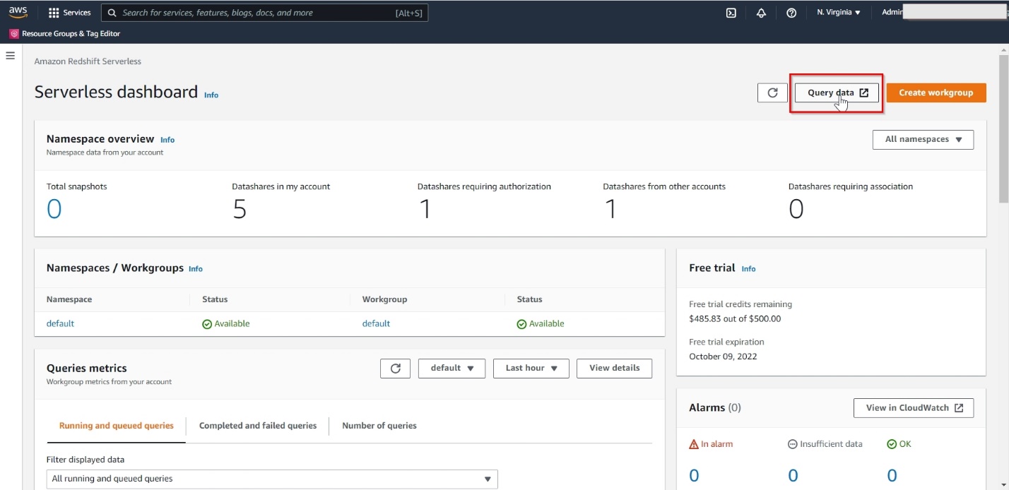
Debu-PandaDebu Panda is a Senior Manager, Product Management, with AWS. He is an industry leader in analytics, application platforms, and database technologies, and has more than 25 years of experience in the IT world. Debu has published numerous articles on analytics, enterprise Java, and databases, and has presented at multiple conferences such as AWS re:Invent, Oracle Open World, and Java One. He is lead author of the EJB 3 in Action (Manning Publications 2007, 2014) and Middleware Management (Packt).

Amazon Redshift Serverless – Now Generally Available with New Capabilities

Post Syndicated from Danilo Poccia original https://aws.amazon.com/blogs/aws/amazon-redshift-serverless-now-generally-available-with-new-capabilities/

Last year at re:Invent, we introduced the preview of Amazon Redshift Serverless, a serverless option of Amazon Redshift that lets you analyze data at any scale without having to manage data warehouse infrastructure. You just need to load and query your data, and you pay only for what you use. This allows more companies to build a modern data strategy, especially for use cases where analytics workloads are not running 24-7 and the data warehouse is not active all the time. It is also applicable to companies where the use of data expands within the organization and users in new departments want to run analytics without having to take ownership of data warehouse infrastructure.

Today, I am happy to share that Amazon Redshift Serverless is generally available and that we added many new capabilities. We are also reducing Amazon Redshift Serverless compute costs compared to the preview.

You can now create multiple serverless endpoints per AWS account and Region using namespaces and workgroups:

  • A namespace is a collection of database objects and users, such as database name and password, permissions, and encryption configuration. This is where your data is managed and where you can see how much storage is used.
  • A workgroup is a collection of compute resources, including network and security settings. Each workgroup has a serverless endpoint to which you can connect your applications. When configuring a workgroup, you can set up private or publicly accessible endpoints.

Each namespace can have only one workgroup associated with it. Conversely, each workgroup can be associated with only one namespace. You can have a namespace without any workgroup associated with it, for example, to use it only for sharing data with other namespaces in the same or another AWS account or Region.

In your workgroup configuration, you can now use query monitoring rules to help keep your costs under control. Also, the way Amazon Redshift Serverless automatically scales data warehouse capacity is more intelligent to deliver fast performance for demanding and unpredictable workloads.

Let’s see how this works with a quick demo. Then, I’ll show you what you can do with namespaces and workgroups.

Using Amazon Redshift Serverless
In the Amazon Redshift console, I select Redshift serverless in the navigation pane. To get started, I choose Use default settings to configure a namespace and a workgroup with the most common options. For example, I’ll be able to connect using my default VPC and default security group.

Console screenshot.

With the default settings, the only option left to configure is Permissions. Here, I can specify how Amazon Redshift can interact with other services such as S3, Amazon CloudWatch Logs, Amazon SageMaker, and AWS Glue. To load data later, I give Amazon Redshift access to an S3 bucket. I choose Manage IAM roles and then Create IAM role.

Console screenshot.

When creating the IAM role, I select the option to give access to specific S3 buckets and pick an S3 bucket in the same AWS Region. Then, I choose Create IAM role as default to complete the creation of the role and to automatically use it as the default role for the namespace.

Console screenshot.

I choose Save configuration and after a few minutes the database is ready for use. In the Serverless dashboard, I choose Query data to open the Redshift query editor v2. There, I follow the instructions in the Amazon Redshift Database Developer guide to load a sample database. If you want to do a quick test, a few sample databases (including the one I am using here) are already available in the sample_data_dev database. Note also that loading data into Amazon Redshift is not required for running queries. I can use data from an S3 data lake in my queries by creating an external schema and an external table.

The sample database consists of seven tables and tracks sales activity for a fictional “TICKIT” website, where users buy and sell tickets for sporting events, shows, and concerts.

Sample database tables relations

To configure the database schema, I run a few SQL commands to create the users, venue, category, date, event, listing, and sales tables.

Console screenshot.

Then, I download the tickitdb.zip file that contains the sample data for the database tables. I unzip and load the files to a tickit folder in the same S3 bucket I used when configuring the IAM role.

Now, I can use the COPY command to load the data from the S3 bucket into my database. For example, to load data into the users table:

copy users from 's3://MYBUCKET/tickit/allusers_pipe.txt' iam_role default;

The file containing the data for the sales table uses tab-separated values:

copy sales from 's3://MYBUCKET/tickit/sales_tab.txt' iam_role default delimiter '\t' timeformat 'MM/DD/YYYY HH:MI:SS';

After I load data in all tables, I start running some queries. For example, the following query joins five tables to find the top five sellers for events based in California (note that the sample data is for the year 2008):

select sellerid, username, (firstname ||' '|| lastname) as sellername, venuestate, sum(qtysold)
from sales, date, users, event, venue
where sales.sellerid = users.userid
and sales.dateid = date.dateid
and sales.eventid = event.eventid
and event.venueid = venue.venueid
and year = 2008
and venuestate = 'CA'
group by sellerid, username, sellername, venuestate
order by 5 desc
limit 5;

Console screenshot.

Now that my database is ready, let’s see what I can do by configuring Amazon Redshift Serverless namespaces and workgroups.

Using and Configuring Namespaces
Namespaces are collections of database data and their security configurations. In the navigation pane of the Amazon Redshift console, I choose Namespace configuration. In the list, I choose the default namespace that I just created.

In the Data backup tab, I can create or restore a snapshot or restore data from one of the recovery points that are automatically created every 30 minutes and kept for 24 hours. That can be useful to recover data in case of accidental writes or deletes.

Console screenshot.

In the Security and encryption tab, I can update permissions and encryption settings, including the AWS Key Management Service (AWS KMS) key used to encrypt and decrypt my resources. In this tab, I can also enable audit logging and export the user, connection, and user activity logs.

Console screenshot.

In the Datashares tab, I can create a datashare to share data with other namespaces and AWS accounts in the same or different Regions. In this tab, I can also create a database from a share I receive from other namespaces or AWS accounts, and I can see the subscriptions for datashares managed by AWS Data Exchange.

Console screenshot.

When I create a datashare, I can select which objects to include. For example, here I want to share only the date and event tables because they don’t contain sensitive data.

Console screenshot.

Using and Configuring Workgroups
Workgroups are collections of compute resources and their network and security settings. They provide the serverless endpoint for the namespace they are configured for. In the navigation pane of the Amazon Redshift console, I choose Workgroup configuration. In the list, I choose the default namespace that I just created.

In the Data access tab, I can update the network and security settings (for example, change the VPC, the subnets, or the security group) or make the endpoint publicly accessible. In this tab, I can also enable Enhanced VPC routing to route network traffic between my serverless database and the data repositories I use (for example, the S3 buckets used to load or unload data) through a VPC instead of the internet. To access serverless endpoints that are in another VPC or subnet, I can create a VPC endpoint managed by Amazon Redshift.

Console screenshot.

In the Limits tab, I can configure the base capacity (expressed in Redshift processing units, or RPUs) used to process my queries. Amazon Redshift Serverless scales the capacity to deal with a higher number of users. Here I also have the option to increase the base capacity to speed up my queries or decrease it to reduce costs.

In this tab, I can also set Usage limits to configure daily, weekly, and monthly thresholds to keep my costs predictable. For example, I configured a daily limit of 200 RPU-hours, and a monthly limit of 2,000 RPU-hours for my compute resources. To control the data-transfer costs for cross-Region datashares, I configured a daily limit of 3 TB and a weekly limit of 10 TB. Finally, to limit the resources used by each query, I use Query limits to time out queries running for more than 60 seconds.

Console screenshot.

Availability and Pricing
Amazon Redshift Serverless is generally available today in the US East (Ohio), US East (N. Virginia), US East (Oregon), Europe (Frankfurt), Europe (Ireland), Europe (London), Europe (Stockholm), and Asia Pacific (Seoul), Asia Pacific (Singapore), Asia Pacific (Sydney), and Asia Pacific (Tokyo) AWS Regions.

You can connect to a workgroup endpoint using your favorite client tools via JDBC/ODBC or with the Amazon Redshift query editor v2, a web-based SQL client application available on the Amazon Redshift console. When using web services-based applications (such as AWS Lambda functions or Amazon SageMaker notebooks), you can access your database and perform queries using the built-in Amazon Redshift Data API.

With Amazon Redshift Serverless, you pay only for the compute capacity your database consumes when active. The compute capacity scales up or down automatically based on your workload and shuts down during periods of inactivity to save time and costs. Your data is stored in managed storage, and you pay a GB-month rate.

To give you improved price performance and the flexibility to use Amazon Redshift Serverless for an even broader set of use cases, we are lowering the price from $0.5 to $0.375 per RPU-hour for the US East (N. Virginia) Region. Similarly, we are lowering the price in other Regions by an average of 25 percent from the preview price. For more information, see the Amazon Redshift pricing page.

To help you get practice with your own use cases, we are also providing $300 in AWS credits for 90 days to try Amazon Redshift Serverless. These credits are used to cover your costs for compute, storage, and snapshot usage of Amazon Redshift Serverless only.

Get insights from your data in seconds with Amazon Redshift Serverless.

— Danilo