Create and reuse governed datasets in Amazon QuickSight with new Dataset-as-a-Source feature

Post Syndicated from Shailesh Chauhan original https://aws.amazon.com/blogs/big-data/create-and-reuse-governed-datasets-in-amazon-quicksight-with-new-dataset-as-a-source-feature/

Amazon QuickSight is a fast, cloud-powered, business intelligence (BI) service that makes it easy to deliver insights to everyone in your organization. QuickSight recently introduced Dataset-as-a-Source, a new feature that allows data owners to create authoritative datasets that can then be reused and further extended by thousands of users across the enterprise. This post walks through an example of how QuickSight makes it easy to create datasets that are reusable and easy to govern, with Dataset-as-a-source.

Introducing Dataset-as-a-Source

Dataset-as-a-Source allows QuickSight authors and data owners to create authoritative datasets, as a single source of truth, that either use the QuickSight SPICE in-memory engine, or directly query the underlying database. These datasets may contain data from a single table from a single database, or a combination of data across multiple data sources, including flat files, software as a service (SaaS) sources, databases, and data warehouses. Data owners with a deep understanding of the data can predefine metrics and calculations in the dataset with metadata that makes it easy for authors to understand and consume this data.

After you create these authoritative datasets, you can share them with authors who want to consume this data – either directly on a per-user or group basis, or using shared folders in QuickSight. Authors can now simply use these datasets for their dashboard creation activities, or choose to further augment these datasets by adding additional calculated fields or joining them with other data that is relevant to them. Any updates made by the data owner to the authoritative dataset automatically cascades to the downstream datasets created by individual authors using those datasets. This provides the organization with a secure, governed, and effortless data sharing process that can scale to thousands of authors as needed, without any server setup or data silos on client desktops.

Dataset-as-a-Source example use case

This example use case uses the Amazon Customer Reviews Data. It is public data stored in the us-east-1 Region. You have the following three tables:

  • product_reviews – Customer reviews for a specific product
  • customer – Customer profile data
  • customer_address – Customer address information

The following diagram shows the relationship of the three tables.
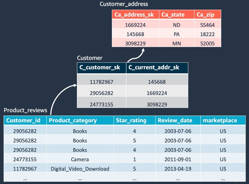
In the following sections, we explain the process of using Dataset-as-a-Source using the tables from the preceding schema.

Create central datasets

Let’s say you’re part of the central data engineering team that has access to the preceding data with three tables in a database. Your team serves over 100 business analysts across 10 different teams in eight countries, namely the Coupons team, Outbound Marketing team, Mobile Platform team, and Recommendations team. Analysts on each team want to analyze product and customer data along with data specific to their teams.

Rather than manually creating and maintaining several unconnected datasets for each team, your team created a central dataset. You created the central Product and Customer dataset by joining the three tables in a schema. Dashboard performance and query costs are optimized for large central dataset with Dynamic Querying. Dynamic Querying enables direct query datasets that contain joined tables to run more efficiently. Joins are applied dynamically so that only the subset of tables needed to render a visual are used in the join. Your team also created a key metric (calculated field): Average Rating. All of these teams use the Average Rating metric as a base to analyze their own business line. Its definition is: Average Rating = Sum(Star_rating) / Unique_Count(Start_rating).

Reuse and join with other datasets

Individual teams reused the central Product and Customer dataset and joined it with the data of their own, to create their own datasets. For example, the Marketing team wanted to understand how their team helped improving the product ratings. Therefore, they combined the central Product and Customer dataset with campaign data to create a new dataset: Marketing – Product & Customer Rating. Similarly, the Mobile Platform team combined mobile data with the Product and Customer dataset to understand rating impact on mobile.

With Dataset-as-a-Source, you can centralize data management while allowing each team to customize the data for their own needs, all while syncing updates to the data, such as updates to metric definitions, and maintaining dataset definitions like column names, descriptions, and field folders. Additionally, if these are SPICE datasets, the newly created datasets are created with SPICE as a source, so you don’t reach to the datasource every time a dataset is created or refreshed.

Govern central datasets

You and the central team defined business metrics like Average Rating in the central dataset. With Dataset-as-a-Source, individual teams can use the central dataset without having to redo the work of recreating the field themselves, while extending it with data representing their specific business needs. All teams are able to use a uniform Average Rating metric definition.

Suppose you now want to make a change to the Average Rating definition because of a business operation change. You want to exclude Digital_Video_Download from the product category, and need to provide an updated definition to each team. To make modifications, you have to modify just the central dataset, and the associated datasets get the updates automatically. This saves you time and prevents errors in business metric definitions.

Conclusion

Creating datasets from existing datasets using Dataset-as-a-Source helps you with the following:

  • Dataset governance – Data engineers can easily scale to the needs of multiple teams within their organization by developing and maintaining a few general-purpose datasets that describe the organization’s main data models—without compromising on query performance.
  • Data source management reduction – Analysts spend considerable amounts of time and effort requesting access to databases, managing database credentials, finding the right tables, and managing data refresh schedules. Building new datasets from existing datasets means that analysts don’t have to start from scratch with raw data from databases. They can start with pre-curated data, while also ensuring that on the data source side, optimizations such as workload management can be put in place to ensure optimal performance of backend stores.
  • Metrics accuracy – Creating datasets from existing datasets allows data engineers to centrally define and maintain critical data definitions, such as sales growth and net marginal return, across their company’s many organizations. It also allows them to distribute changes to those definitions, and gives their analysts the ability to get started with visualizing the right data more quickly and reliably.
  • Dataset customization and flexibility – Creating datasets from existing datasets gives analysts more flexibility to customize datasets for their own business needs without worrying about disrupting data for other teams.

This post showed how QuickSight’s Dataset-as-a-Source can help your data management workflows. This feature greatly improves governance and reusability of the datasets. Dataset-as-a-Source is now generally available in Amazon QuickSight Standard and Enterprise Editions in all QuickSight regions. For further details, visit here.


About the Author

Shailesh Chauhan is product managing Amazon QuickSight, AWS’ cloud-native, fully managed BI service. Before QuickSight, Shailesh was global product lead at Uber for all data applications built from ground-up. Earlier, he was a founding team member at ThoughtSpot, where he created world’s first analytics search engine. Shailesh is passionate about building meaningful and impactful products from scratch. He looks forward to helping customers while working with people with great mind and big heart.

Избори ноември 2021: вотът в чужбина е отново под риск

Post Syndicated from original https://yurukov.net/blog/2021/izbori-nov21-risk/

На 14-ти ноември ще се проведат смесени президентски и парламентарни избори. Право да гласуват имат всички български граждани независимо къде се намират. Възможност да гласуват… е, това за пореден път остава сложно.

Срокът за подаване на заявление за гласуване в чужбина изтича в полунощ българско време на вторник 19-ти октомври. Това е третият път, когато събираме заявления по този начин тази година, но е важно да се разбере, че всеки път трябва да се подава ново заявление. Ето най-важните неща на този етап:

  • Подаването на заявление за гласуване в секцията най-близо до Вас, ще Ви улесни и ще ускори изборния процес, тъй като ще сте вече вписани в списъците
  • Дори да подадете заявление, а се окаже, че на 14-ти ноември сте в България, ще може да гласувате в секцията си по постоянен адрес с попълване на декларация (Приложение 17)
  • Вече са одобрени почти 700 секции в чужбина, където в последните 5 години е имало над 100 подадени гласове. Все пак, това не означава, че на тези места местните общости ще имат възможност или разрешение от приемащата страна да организират секции. Затова се свържете с местната си общност, за да научите къде всъщност се организират такива. Изискването за една секция вече е намалено от 60 на 40 заявления.
  • Отпадна изискването за максимум 35 секции в страни извън ЕС. Това означава, че в САЩ и Великобритания, които бяха най-засегнати на предишния вот, ще има възможност за много такива. Отново, потърсете секция наблизо, за да я подкрепите
  • В Германия се очаква проблем, тъй като германските власти са ограничили секциите до 40 места извън консулствата
  • Подаването на заявления освен, че подпомага изборния процес, показва и повишен интерес на съгражданите ни в чужбина към вота

Както знаем, основна роля в организацията на изборния процес в чужбина имат организациите ни и доброволци по места. В голяма степен това са активни българи, които от години се занимава с това, което всъщност следва ЦИК и МВнР да свършат. На всеки вот информираме, призоваваме, изясняваме, намираме помещения, попълваме комисии и нужди.

През годините тази роля рядко е разпознавана, а понякога дори блокирана. Най-фрапантна беше акцията на прокуратурата в последните години да призовава българи в чужбина на разпит заради разследване за изборни измами. Независимо, че няма никакви доказателства за такива или съмнения в документацията, използваха за пореден път писания в жълти медии като повод за сериозна кампания. Той включваше дори задържане на границата за разпит на хора, които не са били уведомени по никакъв начин за това, че са търсени. Обвинения липсваха – прокурорите само им било любопитно. Това отношение и откровеният тормоз накара доста да се откажат не само да помагат с изборите, но и да имат каквото и да е с България. Общата позиция, включително на хора в ЦИК е, че целта на прокуратурата е именно била такава – деморализация на активните българи най-вече в западна Европа.

Независимо от това доста хора продължиха да се занимават, донякъде напук. Резултатът беше рекорден брой заявления за изборите през април. След още един вот и серия от спънки от ЦИК явно на много им е писнало и сега има своеобразен бойкот на изборите. Целта е да има формално споразумение и ефективна съвместна работа между ЦИК, Външно и българските организации в чужбина. Това е нещо, за което се настоява от над десетилетие, но така и не получихме някакъв отговор. Тази умора и бойкот поставя пред реален риск изборите в чужбина, защото е практически невъзможно консулствата ни с крайно недостатъчния им персонал и ресурси да организират дори част от секциите.

Тъй като ЦИК далеч не се слави с разум и трезва преценка, може да очакваме сериозни проблеми в следващия месец. Независимо, че 700 секции са принципно одобрени независимо от заявленията, надали ще има кой да плати за помещенията, да попълни комисиите и да свърши всичката работа около вота, която остава скрита за обикновения гласоподавател.

Всичко това, както и умората от поредния вот, обяснява намаленият брой заявления този път. За април събрахме 85815 заявления. За юли – 70960. Ако поддържаме сегашната тенденция сега ще има около 42 хиляди или двойно по-малко от първите избори за годината. Друга причина, макар не основна, е времето на събиране. Докато периода за подаване на заявления в началото на годината беше 29 дни, сега е едва 19. За вота през юли беше 24 дни. Тук виждате прогресията за събиране на заявления по дни от откриването на електронния формуляр.

Следейки активността по дни към този етап на кампанията по събиране виждаме, че средният брой заявления на ден е останал относително същия в САЩ и Турция. В Испания е намалял леко. В Германия и Великобритания е паднал повече от половина. Ако моделираме активността от предишните вотове ще очакваме сериозен спад с между 30 и 50% навсякъде.

Както споменах по-горе, това няма да се отрази непременно на броя на секциите – основен риск за това е отказа на ЦИК да говори с хората, които всъщност им вършат работата зад граница. Липсата на заявления обаче ще остави списъците празни, което ще забави допълнително изборния ден.

Както и предишни години, може да следите активността на подаването на заявления в реално време на таблицата и картата на Glasuvam.org. Ще публикувам картата със секциите, когато станат известни и официално потвърдени.

The post Избори ноември 2021: вотът в чужбина е отново под риск first appeared on Блогът на Юруков.

Revisiting BetterTLS: Certificate Path Building

Post Syndicated from Netflix Technology Blog original https://netflixtechblog.com/revisiting-bettertls-certificate-path-building-4c978b79843f

By Ian Haken

Last year the AddTrust root certificate expired and lots of clients had a bad time. Some Roku devices weren’t working right, Heroku had problems, and some folks couldn’t even curl. In the aftermath Ryan Sleevi wrote a really great blog post not just about the issue of this one certificate’s expiry, but the problem that so many TLS implementations have in general with certificate path building. If you haven’t read that blog post, you should. This post is probably going to make a lot more sense if you’ve read that one first, so go ahead and read it now.

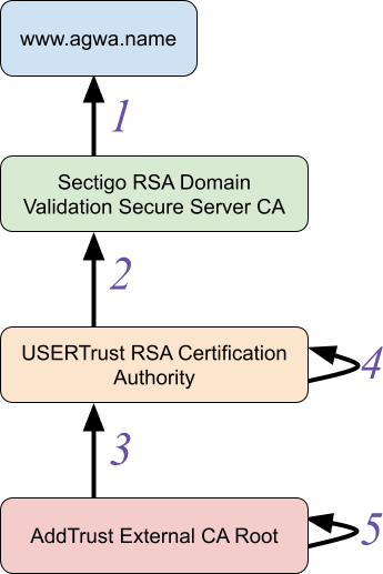
To recap that previous AddTrust root certificate expiry, there was a certificate graph that looked like this:

The AddTrust certificate graph

This is a real example, and you can see the five certificates in the above graph here:

  1. www.agwa.name (leaf certificate)
  2. Sectigo RSA Domain Validation Secure Server CA (intermediate CA)
  3. USERTrust RSA Certification Authority (intermediate CA)
  4. USERTrust RSA Certification Authority (self-signed)
  5. AddTrust External CA Root (self-signed)

The important thing to understand about a certificate graph is that the boxes represent entities (meaning an X.500 Distinguished Name and public key). Entities are things you trust (or don’t, as the case may be). The arrows between entities represent certificates: a way to extend trust from one entity to another. This means that if you trust either the “USERTrust RSA Certification Authority” entity or the “AddTrust External CA Root” entity, you should be able to discover a chain of trust from that trusted entity (the “trust anchor”) down to “www.agwa.name”, the “end-entity”.

(Note that the self-signed certificates (4 and 5) are often useful for defining trusted entities, but aren’t going to be important in the context of path building.)

The problem that occurred last summer started because certificate 3 expired. The “USERTrust RSA Certificate Authority” was relatively new and not directly trusted by many clients and so most servers would send certificates 1, 2, and 3 to clients. If a client only trusted “AddTrust External CA Root” then this would be fine; that client can build a certificate chain 1 ← 2 ← 3 and see that they should trust www.agwa.name’s public key. On the other hand, if the client trusts “USERTrust RSA Certification Authority” then that’s also fine; it only needs to build a chain 1 ← 2.

The problem that arose was that some clients weren’t good at certificate path building (even though this is a fairly simple case of path building compared to the next example below). Those clients didn’t realize that they could stop building a chain at 2 if they trusted “USERTrust RSA Certification Authority”. So when certificate 3 expired on May 30, 2020, these clients treated the entire collection of certificates sent by the server as invalid and would no longer establish trust in the end-entity.

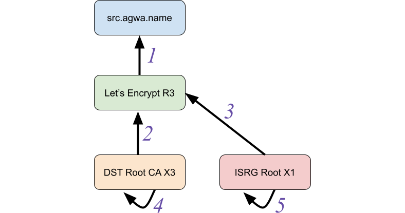
Even though that story is a year old and was well covered then, I’m retelling it here because a couple of weeks ago something kind of similar happened: a certificate for the Let’s Encrypt R3 CA expired (certificate 2 below) on September 30, 2021. This should have been fine; the Let’s Encrypt R3 entity also has a certificate signed by the ISRG Root X1 CA (3) which nowadays is trusted by most clients.

The Let’s Encrypt R3 Certificate Graph
  1. src.agwa.name (leaf certificate)
  2. Let’s Encrypt R3 (signed by DST Root CA X3)
  3. Let’s Encrypt R3 (signed by ISRG Root X1)
  4. DST Root CA X3 (self-signed)
  5. ISRG Root X1 (self-signed)

But predictably, even though it’s been a year since Ryan’s post, lots of services and clients had issues. You should read Scott Helme’s full post-mortem on the event to understand some of the contributing factors, but one big problem is that most TLS implementations still aren’t very good at path building. As a result, servers generally can’t send a complete collection of certificates down to clients (containing different possible paths to different trust anchors) which makes it hard to host a service that both old and new devices can talk to.

Maybe it’s because I saw history repeating or maybe it’s because I had just listened to Ryan Sleevi talk about the history of web PKI, but the whole episode really made me want to get back to something I had been wanting to do for a while. So over the last couple of weeks I set some time aside, started reading some RFCs, had to get more coffee, finished reading some RFCs, and finally started making certificates. The end result is the first major update to BetterTLS since its first release: a new suite of tests to exercise TLS implementations’ certificate path building. As a bonus, it also checks whether TLS implementations apply certain validity checks. Some of the checks are part of RFCs, like Basic Constraints, while others are not fully standardized, like distrusting deprecated signature algorithms and enforcing EKU constraints on CAs.

I found the results of applying these tests to various TLS implementations pretty interesting, but before I get into those results let me give you a few more details about why TLS implementations should be doing good path building and why we care about it.

What is Certificate Path Building?

If you want the really detailed answer to “What is Certificate Path Building” you can take a look at RFC 4158. But in short, certificate path building is the process of building a chain of trust from some end entity (like the blue boxes in the examples above) back to a trust anchor (like the ISRG Root X1 CA) given a collection of certificates. In the context of TLS, that collection of certificates is sent from the server to the client as part of the TLS handshake. A lot of the time, that collection of certificates is actually already an ordered sequence of certificates from end-entity to trust anchor, such as in the first example where servers would send certificates 1, 2, 3. This happens to already be a chain from “www.agwa.name” to “AddTrust External CA Root”.

But what happens if we can’t be sure what trust anchor the client has, such as the second example above where the server doesn’t know if the client will trust DST Root CA X3 or ISRG Root X1? In this case the server could send all the certificates (1, 2, and 3) and let the client figure out which path makes sense (either 1 ← 2, or 1 ← 3). But if the client expects the server’s certificates to simply be a chain already, the sequence 1 ← 2 ← 3 is going to fail to validate.

Why Does This Matter?

The most important reason for clients to support robust path building is that it allows for agility in the web PKI ecosystem. For example, we can add additional certificates that conform to new requirements such as SHA-1 deprecation, validity length restrictions, or trust anchor removal, all while leaving existing certificates in place to preserve legacy client functionality. This allows static, infrequently updated, or intentionally end-of-lifed clients to continue working while browsers (which frequently enforce new constraints like the ones mentioned above) can take advantage of the additional certificates in the handshake that conform to the new requirements.

In particular, Netflix runs on a lot of devices. Millions of them. The reality though is that the above description applies to many of them. Some devices only run older versions of Android of iOS. Some are embedded devices that no longer receive updates. Regardless of the specifics, the update cadence (if one exists) for those devices is outside of our control. But ideally we’d love it if every device that used to work just kept working. To that end, it’s helpful to know what trade-offs we can make in terms of agility versus retaining support for every device. Are those devices stuck using certain signature algorithms or cipher suites? Will those devices accept a certificate set that includes extra certificates with other alternate signature algorithms?

As service owners, having test suites that can answer these questions can guide decision making. On the other hand, TLS library implementers using these test suites can ensure that applications built with their libraries operate reliably throughout churn in the web PKI ecosystem.

An Aside About Agility

More than 4 years passed between publication of the first draft of the TLS 1.3 specification and the final version. An impressive amount of consideration went into the design of all of the versions of the TLS and SSL protocols and it speaks to the designers’ foresight and diligence that a single server can support clients speaking SSL 3.0 (final specification released 1996) all the way up to TLS 1.3 (final specification released 2018).

(Although I should say that in practice, supporting such a broad set of protocol versions on a single server is probably not a good idea.)

The reason that TLS protocol can support this is because agility has been designed into the system. The client advertises the TLS versions, cipher suites, and extensions it supports and the server can make decisions about the best supported version of those options and negotiate the details in its response. Over time this has allowed the ecosystem to evolve gracefully, supporting new cryptographic primitives (like elliptic curve cryptography) and deprecating old ones (like the MD5 hash algorithm).

Unfortunately the TLS specification has not enabled the same agility with the certificates that it relies on in practice. While there are great specifications like RFC 4158 for how to think about certificate path building, TLS specifications up to 1.2 only allowed for server to present “the chain”:

This is a sequence (chain) of certificates. The sender’s certificate MUST come first in the list. Each following certificate MUST directly certify the one preceding it.

Only in TLS 1.3 did the specification allow for greater flexibility:

The sender’s certificate MUST come in the first CertificateEntry in the list. Each following certificate SHOULD directly certify the one immediately preceding it.
…
Note: Prior to TLS 1.3, “certificate_list” ordering required each certificate to certify the one immediately preceding it; however, some implementations allowed some flexibility. Servers sometimes send both a current and deprecated intermediate for transitional purposes, and others are simply configured incorrectly, but these cases can nonetheless be validated properly. For maximum compatibility, all implementations SHOULD be prepared to handle potentially extraneous certificates and arbitrary orderings from any TLS version, with the exception of the end-entity certificate which MUST be first.

This change to the specification is hugely significant because it’s the first formalization that TLS implementations should be doing robust path building. Implementations which conform to this are far more likely to continue operating in a PKI ecosystem undergoing frequent changes. If more TLS implementations can tolerate changes, then web PKI ecosystem will be in a place where it is able to undergo those changes. And ultimately this means we will be able to update best practices and retain trust agility as time goes on, making the web a more secure place.

It’s hard to imagine a world where SSL and TLS were so inflexible that we wouldn’t have been able to gracefully transition off of MD5 or transition to PFS cipher suites. I’m hopeful that this update to the TLS specification will help bring the same agility that has existed in the TLS protocol itself to the web PKI ecosystem.

Test Results

So what does the new test suite in BetterTLS tell us about the state of certificate path building in TLS implementations? The good news is that there has been some improvement in the state of the world since Ryan’s roundup last year. The bad news is that that improvement isn’t everywhere.

The test suite both identifies what relevant features a TLS implementation supports (like default distrust of deprecated signing algorithms) and evaluates correctness. Here’s a quick enumeration of what features this test suite looks for:

  • Branching Path Building: Implementations that support “branching” path building can handle cases like the Let’s Encrypt R3 example above where an entity has multiple issuing certificates and the client needs to check multiple possible paths to find a route to a trust anchor. Importantly, as invalid certificates are found during path building (for all of the reasons listed below) the implementation should be able to pick an alternate issuer certificate to continue building a path. This is the primary feature of interest in this test suite.
  • Certificate expiration: Implementations should treat expired certificates as invalid during path building. This is a pretty straightforward expectation and fortunately all the tested implementations were properly verifying this.
  • Name constraints: Implementations should treat certificates with a name constraint extension in conflict with the end entity’s identity as invalid. Check out BetterTLS’s name constraints test suite for more thorough evaluations of this evaluation. All of the implementations tested below correctly evaluated the simple name constraints check in this test suite.
  • Bad Extended Key Usage (EKU) on CAs: This check tests whether an implementation rejects CA certificates with an Extended Key Usage extension that is incompatible with the end-entity’s use of the certificate for TLS server authentication. The Mozilla Certificate Policy FAQ states:

Inclusion of EKU in CA certificates is generally allowed. NSS and CryptoAPI both treat the EKU extension in intermediate certificates as a constraint on the permitted EKU OIDs in end-entity certificates. Browsers and certificate client software have been using EKU in intermediate certificates, and it has been common for enterprise subordinate CAs in Windows environments to use EKU in their intermediate certificates to constrain certificate issuance.

While many implementations support the semantics of an incompatible EKU in CAs as a reason to treat a certificate as invalid, RFCs do not require this behavior so we do see several implementations below not applying this verification.

  • Missing Basic Constraints Extension: This check tests whether the implementation rejects paths where a CA is missing the Basic Constraints extension. RFC 5280 requires that all CAs have this extension, so all implementations should support this.
  • Not a CA: This check tests whether the implementation rejects paths where a CA has a Basic Constraints extension, but that extension does not identify the certificate as being a CA. Similarly to the above, all implementations should support this and fortunately all of the implementations tested applied this check correctly.
  • Deprecated Signing Algorithm: This check tests whether the implementation rejects certificates that have been signed with an algorithm that is considered deprecated (in particular, with an algorithm using SHA-1). Enforcement of SHA-1 deprecation is not universally present in all TLS implementations at this point, so we see a mix of implementations below that do and do not apply it.

For more information about these checks, check out the repository’s README. Now on to the results!

webpki

webpki is a rust library for validating web PKI certificates. It’s the underlying validation mechanism for the rustls library that I actually tested. webpki shows up as the hero of the non-browser TLS implementations, supporting all of the features and having a 100% test pass rate. webpki is primarily maintained by Brian Smith who also worked on the mozilla::pkix codebase that’s used by Firefox.

Go

Go didn’t distrust deprecated signature algorithms by default (although looking at the issues tracker, an update was merged to change this long before I started working on this test suite; it should land in Go 1.18), but otherwise supported all the features in the test suite. However, while it supported EKU constraints on CAs the test suite discovered a bug that causes path building to fail under certain conditions when only a subset of paths have an EKU constraint.

Upon inspection, the Go x509 library validates most certificate constraints (like expiration and name constraints) as it builds paths, but EKU constraints are only applied after candidate paths are found. This looks to be a violation of Sleevi’s Rule, which probably explains why the EKU corner case causes Go to have a bad time:

Even if a library supports path building, doing some form of depth-first search in the PKI graph, the next most common mistake is still treating path building and path verification as separable, independent steps. That is, the path builder finds “a chain” that is rooted in a trusted CA, and then completes. The completed chain is then handed to a path verifier, which asks “Does this chain meet all the caller’s/application’s requirements”, and returns a “Yes/No” answer. If the answer is “No”, you want the path builder to consider those other paths in the graph, to see if there are any “Yes” paths. Yet if the path building and verification steps are different, you’re bound to have a bad time.

Java

I didn’t evaluate JDKs other than OpenJDK, but the latest version of OpenJDK 11 actually performed quite well. This JDK didn’t enforce EKU constraints on CAs or distrust certificates signed with SHA-1 algorithms. Otherwise, the JDK did a good job of building certificate paths.

PKI.js

The PKI.js library is a javascript library that can perform a number of PKI-related operations including certificate verification. It’s unclear if the “certificate chain validator” is meant to support complex certificate sets or if it was only meant to handle pre-validated paths, but the implementation fared poorly against the test suite. It didn’t support EKU constraints, distrust deprecated signature algorithms, didn’t perform any branching path building, and failed to validate even a simple “chain” when a parent certificate has expired but the intermediate was already trusted (this is the same issue OpenSSL ran into with the expired AddTrust certificate last year).

Even worse, when the certificate pool had a cycle (like in RFC 4158 figure 7), the validator got stuck in an infinite loop.

OpenSSL

In short, OpenSSL doesn’t appear to have changed significantly since Ryan’s roundup last year. OpenSSL does support the less ubiquitous validation checks (such as EKU constraints on CAs and distrusting deprecated signing algorithms), but it still doesn’t support branching path building (only non-branching chains).

LibreSSL

LibreSSL showed significant improvement over last year’s evaluation, which appears to be largely attributable to Bob Beck’s work on a new x509 verifier in LibreSSL 3.2.2 based on Go’s verifier. It supported path building and passed all of the non-skipped tests. As with other implementations it didn’t distrust deprecated algorithms by default. The one big surprise though is that it also didn’t distrust certificates missing the Basic Constraints extension, which as we described above is strictly required by the RFC 5280 spec:

If the basic constraints extension is not present in a version 3 certificate, or the extension is present but the cA boolean is not asserted, then the certified public key MUST NOT be used to verify certificate signatures.

BoringSSL

BoringSSL performed similarly to OpenSSL. Not only did it not support any path building (only non-branching chains), but it also didn’t distrust deprecated signature algorithms.

GnuTLS

GnuTLS looked just like OpenSSL in its results. It also supported all the validation checks in the test suite (EKU constraints, deprecated signature algorithms) but didn’t support branching path building.

Browsers

By and large, browsers (or the operating system libraries they utilize) do a good job of path building.

Firefox (all platforms)

Firefox didn’t distrust deprecated signature algorithms, but otherwise supported path building and passed all tests.

Chrome (all platforms)
Chrome supported all validation cases and passed all tests.

Microsoft Edge (Windows)
Edge supported all validation cases and passed all tests.

Safari (MacOS)
Safari didn’t support EKU constraints on CAs but did pass simple branching path building test cases. However, it failed most of the more complicated path building test cases (such as cases with cycles).

Summary

+-----------+----------+-------------------+---+-------------------+
| | Supports | Distrusts SHA-1 |EKU| Has other errors? |
| | branching| signing algs? | | |
+-----------+----------+-------------------+---+-------------------+
| webpki | ✓ | ✓ | ✓ | |
+-----------+----------+-------------------+---+-------------------+| Go | ✓ | ✖ (Fixed in 1.18) | ✓ | EKU bug |
+-----------+----------+-------------------+---+-------------------+
| Java | ✓ | ✖ | ✖ | |
+-----------+----------+-------------------+---+-------------------+
| PKI.js | ✖ | ✖ | ✖ | Fails even non- |
| | | | | branching path |
| | | | | building cases, |
| | | | | has infinite loop |
+-----------+----------+-------------------+---+-------------------+
| OpenSSL | ✖ | ✓ | ✓ | |
+-----------+----------+-------------------+---+-------------------+
| LibreSSL | ✓ | ✖ | ✓ | Doesn't require |
| | | | | Basic Constraints |
+-----------+----------+-------------------+---+-------------------+
| BoringSSL | ✖ | ✖ | ✓ | |
+-----------+----------+-------------------+---+-------------------+
| GnuTLS | ✖ | ✓ | ✓ | |
+-----------+----------+-------------------+---+-------------------+
| Firefox | ✓ | ✖ | ✓ | |
+-----------+----------+-------------------+---+-------------------+
| Chrome | ✓ | ✓ | ✓ | |
+-----------+----------+-------------------+---+-------------------+
| Edge | ✓ | ✓ | ✓ | |
+-----------+----------+-------------------+---+-------------------+
| Safari | Kind of? | ✓ | ✖ | Failed complex |
| | | | | path finding cases|
+-----------+----------+-------------------+---+-------------------+

Closing Thoughts

For most of the history of TLS, implementations have been pretty poor at certificate path building (if they supported it at all). In fairness, until recently the TLS specifications asserted that servers MUST behave in such a way that didn’t require clients to implement certificate path building.

However the evolution of the web PKI ecosystem has necessitated flexibility and this has been more directly codified in the TLS 1.3 specification. If you work on a TLS implementation, you really really ought to take heed of these new expectations in the TLS 1.3 specification. We’re going to have a lot more stability on the web if implementations can do good path building.

To be clear, it doesn’t need to be every implementation’s goal to pass every test in this suite. I’ll be the first to admit that the test suite contains some more pathological test cases than you’re likely to see in web PKI in practice. But at a minimum you should look at the changes that have occurred in the web PKI ecosystem in the past decade and be confident that your library supports enough path building to easily handle transitions (such as servers sending multiple possible paths to a trust anchor). And passing all of the tests in the BetterTLS test suite is a useful metric for establishing that confidence.

It’s important to make sure clients are forward-compatible with changes to the web PKI, because it’s not a matter of “if” but “when.” In Scott’s own words:

One thing that’s certain is that this event is coming again. Over the next few years we’re going to see a wide selection of Root Certificates expiring for all of the major CAs and we’re likely to keep experiencing the exact same issues unless something changes in the wider ecosystem.

If you are in a position to choose between different client-side TLS libraries, you can use these test results as a point of consideration for which libraries are most likely to weather those changes.

And if you are a service owner, it is important to know your customers. Will they be able to handle a transition from RSA to ECDSA? Will they be able to handle a transition from ECDSA to a post-quantum signature algorithm? Will they be able to handle having multiple certificates in a handshake when an old trust is expiring or no longer trusted by new clients? Knowing your clients can help you be resilient and set up appropriate configurations and endpoints to support them.

Standards, security base lines, and best practices in web PKI have been rapidly changing over the last few years and are only going to keep changing. Whether you implement TLS or just consume it, whether it’s a distrusted CA, a broken signature algorithm, or just the expiry of a certificate in good standing, it’s important to make sure that your application will be able to handle the next big change. We hope that BetterTLS can play a part in making that easier!


Revisiting BetterTLS: Certificate Path Building was originally published in Netflix TechBlog on Medium, where people are continuing the conversation by highlighting and responding to this story.

Visualizing AWS Step Functions workflows from the AWS Batch console

Post Syndicated from Eric Johnson original https://aws.amazon.com/blogs/compute/visualizing-aws-step-functions-workflows-from-the-aws-batch-console/

This post written by Dhiraj Mahapatro, Senior Specialist SA, Serverless.

AWS Step Functions is a low-code visual workflow service used to orchestrate AWS services, automate business processes, and build serverless applications. Step Functions workflows manage failures, retries, parallelization, service integrations, and observability so builders can focus on business logic.

AWS Batch is one of the service integrations that are available for Step Functions. AWS Batch enables users to more easily and efficiently run hundreds of thousands of batch computing jobs on AWS. AWS Batch dynamically provisions the optimal quantity and compute resource classifications based on the volume and specific resource requirements of the batch jobs submitted. AWS Batch plans, schedules, and runs batch computing workloads across the full range of AWS compute services and features, such as AWS Fargate, Amazon EC2, and spot instances.

Now, Step Functions is available to AWS Batch users through the AWS Batch console. This feature enables AWS Batch users to augment compute options and have additional orchestration capabilities to manage their batch jobs.

This blog walks through Step Functions integration in AWS Batch console and shows how AWS Batch users can efficiently use Step Functions workflow orchestrators in batch workloads. A sample application also highlights the use of AWS Lambda as a compute option for AWS Batch.

Introducing workflow orchestration in AWS Batch console

Today, AWS users use AWS Batch for high performance computing, post-trade analytics, fraud surveillance, screening, DNA sequencing, and more. AWS Batch minimizes human error, increases speed and accuracy, and reduces costs with automation so that users can refocus on evolving the business.

In addition to using compute-intensive tasks, users sometimes need Lambda for simpler, less intense processing. Users also want to combine the two in a single business process that is scalable and repeatable.

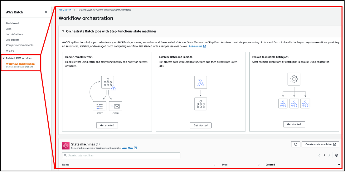
Workflow orchestration (powered by Step Functions) in AWS Batch console allows orchestration of batch jobs with Step Functions state machine:

Workflow orchestration in Batch console

Workflow orchestration in Batch console

Using batch-related patterns from Step Functions

Error handling

Step Functions natively handles errors and retries of its workflows. Users rely on this native error handling mechanism to focus on building business logic.

Workflow orchestration in AWS Batch console provides common batch-related patterns that are present in Step Functions. Handling errors while submitting batch jobs in Step Functions is one of them.

Getting started with orchestration in Batch

Getting started with orchestration in Batch

  1. Choose Get Started from Handle complex errors.
  2. From the pop-up, choose Start from a template and choose Continue.

A new browser tab opens with Step Functions Workflow Studio. The Workflow Studio designer has a workflow pattern template pre-created. Diving deeper into the workflow highlights that the Step Functions workflow submits a batch job and then handles success and error scenarios by sending Amazon SNS notifications, respectively.

Alternatively, choosing Deploy a sample project from the Get Started pop-up deploys a sample Step Functions workflow.

Deploying a sample project

Deploying a sample project

This option allows creating a state machine from scratch, reviewing the workflow definition, deploying an AWS CloudFormation stack, and running the workflow in Step Functions console.

Deploy and run from console

Deploy and run from console

Once deployed, the state machine is visible in the Step Functions console as:

Viewing the state machine in the AWS Step Functions console

Viewing the state machine in the AWS Step Functions console

Select the BatchJobNotificationStateMachine to land on the details page:

View the state machine's details

View the state machine’s details

The CloudFormation template has already provisioned the required batch job in AWS Batch and the SNS topic for success and failure notification.

To see the Step Functions workflow in action, use Start execution. Keep the optional name and input as is and choose Start execution:

Run the Step Function

Run the Step Function

The state machine completes the tasks successfully by Submitting Batch Job using AWS Batch and Notifying Success using the SNS topic:

The successful results in the console

The successful results in the console

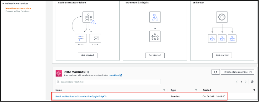
The state machine used the AWS Batch Submit Job task. The Workflow orchestration in AWS Batch console now highlights this newly created Step Functions state machine:

The state machine is listed in the Batch console

The state machine is listed in the Batch console

Therefore, any state machine that uses this task in Step Functions for this account is listed here as a state machine that orchestrates batch jobs.

Combine Batch and Lambda

Another pattern to use in Step Functions is the combination of Lambda and batch job.

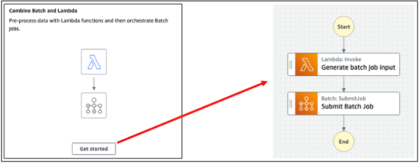
Select Get Started from Combine Batch and Lambda pop-up followed by Start from a template and Continue. This takes the user to Step Functions Workflow studio with the following pattern. The Lambda task generates input for the subsequent batch job task. Submit Batch Job task takes the input and submits the batch job:

Combining AWS Lambda with AWS Step Functions

Combining AWS Lambda with AWS Step Functions

Step Functions enables AWS Batch users to combine Batch and Lambda functions to optimize compute spend while using the power of the different compute choices.

Fan out to multiple Batch jobs

In addition to error handling and combining Lambda with AWS Batch jobs, a user can fan out multiple batch jobs using Step Functions’ map state. Map state in Step Functions provides dynamic parallelism.

With dynamic parallelism, a user can submit multiple batch jobs based on a collection of batch job input data. With visibility to each iteration’s input and output, users can easily navigate and troubleshoot in case of failure.

Easily navigate and troubleshoot in case of failure

Easily navigate and troubleshoot in case of failure

AWS Batch users are not limited to the previous three patterns shown in Workflow orchestration in the AWS Batch console. AWS Batch users can start from scratch and build Step Functions state machine by navigating to the bottom right and using Create state machine:

Create a state machine from the Step Functions console

Create a state machine from the Step Functions console

Create State Machine in AWS Batch console opens a new tab with Step Functions console’s Create state machine page.

Design a workflow visually

Design a workflow visually

Refer building a state machine AWS Step Functions Workflow Studio for additional details.

Deploying the application

The sample application shows fan out to multiple batch jobs pattern. Before deploying the application, you need:

To deploy:

  1. From a terminal window, clone the GitHub repo:
    git clone [email protected]:aws-samples/serverless-batch-job-workflow.git
  2. Change directory:
    cd ./serverless-batch-job-workflow
  3. Download and install dependencies:
    sam build
  4. Deploy the application to your AWS account:
    sam deploy --guided

To run the application using the AWS CLI, replace the state machine ARN from the output of deployment steps:

aws stepfunctions start-execution \
    --state-machine-arn <StepFunctionArnHere> \
    --region <RegionWhereApplicationDeployed> \
    --input "{}"

Step Functions is not limited to AWS Batch’s Submit Job API action

In September 2021, Step Functions announced integration support for 200 AWS Services to enable easier workflow automation. With this announcement, Step Functions is not limited to integrate with AWS Batch’s SubmitJob API but also can integrate with any AWS Batch SDK API today.

Step Functions can automate the lifecycle of an AWS Batch job, starting from creating a compute environment, creating job queues, registering job definitions, submitting a job, and finally cleaning up.

Other AWS service integrations

Step Functions support for 200 AWS Services equates integration with more than 9,000 API actions across these services. AWS Batch tasks in Step Functions can evolve by integrating with available services in the workflow for their pre- and post-processing needs.

For example, batch job input data sanitization can be done inside Lambda and that gets pushed to an Amazon SQS queue or Amazon S3 as an object for auditability purposes.

Similarly, Amazon SNS, Amazon Pinpoint, or Amazon SES can notify once AWS Batch job task is complete.

There are multiple ways to decorate around an AWS Batch job task. Refer to AWS SDK service integrations and optimized integrations for Step Functions for additional details.

Important considerations

Workflow orchestrations in the AWS Batch console only show Step Functions state machines that use AWS Batch’s Submit Job task. Step Functions state machines do not show in the AWS Batch console when:

  1. A state machine uses any other AWS SDK Batch API integration task
  2. AWS Batch’s SubmitJob API is invoked inside a Lambda function task using an AWS SDK client (like Boto3 or Node.js or Java)

Cleanup

The sample application provisions AWS Batch (the job definition, job queue, and ECS compute environment inside a VPC). It also creates subnets, route tables, and an internet gateway. Clean up the stack after testing the application to avoid the ongoing cost of running these services.

To delete the sample application stack, use the latest version of AWS SAM CLI and run:

sam delete

Conclusion

To learn more on AWS Batch, read the Orchestrating Batch jobs section in the Batch developer guide.

To get started, open the workflow orchestration page in the Batch console. Select Orchestrate Batch jobs with Step Functions Workflows to deploy a sample project, if you are new to Step Functions.

This feature is available in all Regions where both Step Functions and AWS Batch are available. View the AWS Regions table for details.

To learn more on Step Functions patterns, visit Serverless Land.

Въпроси и отговори за отказа на РИК и ЦИК да регистрира листата на Демократична България

Post Syndicated from Bozho original https://blog.bozho.net/blog/3834

Тъй като днес се натрупаха доста въпроси по казуса с електронните подписи и листата в Стара Загора, правя компилация от тях и техните отговори:

Въпрос: Внесли ли сте всички документи в електронен вид или само разпечатка на електронния подпис на хартия, както пишеше в някои медии?

Отговор: И РИК на своето заседание, и ЦИК в решението си признават, че всички необходими документи са внесени в електронен вид, в рамките на срока, свалени са от флаш-паметта на компютър на РИК и подписите са проверени. След това РИК в решението си прикриват тези детайли.

Въпрос: Какъв тогава е проблемът, ако всичко е внесено както трябва?

Отговор: Проблемите според РИК и ЦИК са различни. Според РИК липсва „вярно с оригинала“ на хартиена разпечатка на оригиналния документ, без каквато те твърдят, че документите са невалидни (въпреки, че са свалили и проверили оригиналите). Проблемът според ЦИК е, че изобщо не може да се използват електронни подписи, въпреки, че европейският регламент, който приравнява електронния подпис на саморъчен се прилага пряко, а РИК и ЦИК са задължение да приемат електронни документи и да признават квалифицираните електронни подписи без да има предварителна уговорка със заявителя.

Въпрос: Защо твърдите, че има атака от ГЕРБ, при положение, че те отричат, посочвайки, че председателката на РИК 27 е от ИТН?

Отговор: Освен решението за потвърждаване на отказа, ЦИК приема да изпрати на всички районни комисии писмо, с което да събере информация дали има подадени листи с електронен подпис (които биха били в нарушение съгласно мотивите на приетото от ЦИК решение). Предложението за това е на Красимир Ципов от ГЕРБ. Подкрепено, отново, от всички останали (без представителите на ДБ).

Въпрос: Нормално ли е да се внасят листите в последния ден?

Отговор: абсолютно нормално е – на практика всички значими партии го правят в последния ден, защото това дава гъвкавост в особени ситуации. Ако видите решенията на РИК 27, решеняита за регистрация на ДБ, ГЕРБ, БСП, ДПС, ИБНИ и ПП са от 12-ти. Само на ИТН е от 11-ти.

Въпрос: Защо ги подавате с електронен подпис, а не на хартия като всички останали?

Отговор: Този въпрос е принципен – когато твърдим, че дигитализацията е приоритет, е редно да изпозлваме правата си според действащото законодателство. И да ги защитаваме, когато се чуе редовната реплика на администрацията: „Това не може с електронен подпис!“

Въпрос: Това значи ли, че ще останете без листа?

Отговор: Административният съд в Стара Загора ще реши, след като обжалваме пред него.

Материалът Въпроси и отговори за отказа на РИК и ЦИК да регистрира листата на Демократична България е публикуван за пръв път на БЛОГодаря.

Ubuntu 21.10 (Impish Indri) released

Post Syndicated from original https://lwn.net/Articles/872970/rss

The latest release of the Ubuntu Linux distribution is out: Ubuntu 21.10, code named “Impish Indri”. The release notes fills in all of the details for the new features in this version, but the announcement lists some as well:

Ubuntu Desktop 21.10 makes wayland sessions available while using the
Nvidia proprietary driver. PulseAudio 15 introduces support for Bluetooth
LDAC and AptX codecs, as well as HFP Bluetooth profiles providing better
audio quality. The recovery key feature at installation time has been
improved, with the recovery key now optional, stronger and editable.
Ubuntu Desktop 21.10 includes GNOME version 40, with a new and
improved Activities Overview design. Workspaces are now arranged
horizontally, and the overview and app grid are accessed vertically.
Each direction has accompanying keyboard shortcuts, touchpad gestures
and mouse actions.

Ubuntu Server 21.10 integrates recent innovations from key open
infrastructure projects like OpenStack Xena, QEMU 6.0, PHP8, libvirt 7.6,
Kubernetes, and Ceph with advanced life-cycle management tools for
multi-cloud and on-prem operations from bare metal, VMWare and
OpenStack, to every major public cloud.

Turn On, Tune In, Drop the Noise: Achieve Better Cloud Security by Reducing Noise

Post Syndicated from Rapid7 original https://blog.rapid7.com/2021/10/14/turn-on-tune-in-drop-the-noise-achieve-better-cloud-security-by-reducing-noise/

Turn On, Tune In, Drop the Noise: Achieve Better Cloud Security by Reducing Noise

The modern world is full of signals. A select few are critically important, others are interesting or informative, and the overwhelming majority are less useful or painfully irrelevant. All of these signals that are neither useful nor relevant are best categorized as noise.

For security professionals, it’s easy to get lost in this noise. Many of them get email, text, or Slack notifications for every helpdesk ticket that is issued, updated, and closed. The average security manager might get hourly, daily, weekly, and monthly reports from a variety of different tools that they and their teams may or may not interact with on a regular basis. And at some point, the thousands of alarms and notifications that these same tools generate on a weekly basis end up causing mind-numbing alert fatigue that bogs down security teams. Research has found that 75% of companies are actually spending more time chasing down false positives than responding to genuine security incidents, TechRepublic reports.

Are these signals important? Maybe. Are they getting to the right people at the right time? Hopefully. But hope is not enough when it comes to cloud security.

Misconfigurations add to the clamor

Our 2021 Cloud Misconfigurations Report confirms that data breaches attributed to cloud misconfigurations are still a significant concern for enterprises across all industries. It’s hard to go a few days without hearing of yet another incident in which the data is breached, leaked, or otherwise mishandled. In fact, according to our data, there are 2.3 data breaches per week… and that number doesn’t include those that aren’t reported.

There are many reasons why cloud misconfigurations remain such a significant problem. One contributing factor that continues to be front and center is the overabundance of noise that comes with the ephemeral, fast-evolving nature of cloud environments. The cadence at which security teams are bombarded with alerts and notifications is overwhelming. Yet these teams are still responsible for ensuring the security of the sensitive data in complex cloud environments.

As stewards of this data, security teams must have a comprehensive cloud security solution that allows them to continuously monitor and react to threats. Security teams are trying to understand the high-priority issues that actually matter, all while keeping up with the fast, continuous pace of innovation. To accomplish this, they must invest in a solution that gets the right signals to the right people at the right time, through the right means.

Many of the tools that enterprises use to be better, faster, and stronger are incredibly powerful, but sometimes this power can create chaos and noise. This is especially true for the many cloud security solution types available today. Almost any cloud security tool should be able to tell you if you have a storage bucket open to the public. But what if that storage bucket is meant to be open? What if it’s in a protected environment? What if your developers have created strategic exemptions to specific rules for a legitimate reason?

At best, the security team receives the alert, investigates it, and then determines that there is no issue. While this is by no means an efficient or scalable approach to handling cloud security incidents, nothing catastrophically bad has happened. There wasn’t an actual data breach, and the developers weren’t impeded by security, since their instance wasn’t shut down automatically.

But there are other, more likely scenarios to consider. For example, what if the security team’s investigation of a harmless exemption diverts their attention from a more critical alert? If the real alert is ignored amid the noise and the threat remains unresolved, the entire organization is at risk. As we know, there are huge repercussions of a data breach — from financial to legal to operational to reputational. In fact, according to the Ponemon Institute, the average cost of a data breach is now up to $4.24 million.

Cutting through to the signal

With this much at stake, security teams can’t become immune to critical alerts or blind to the information that is essential to maintaining continuous cloud security. InsightCloudSec helps reduce noise through its extensibility and the level of granularity through which you can determine the scope of alerts (and actions in response to those alerts).

Unified visibility and terminology

InsightCloudSec sets the noise-reduction table by providing a single source of visibility into cloud environments that spans across AWS, GCP, Microsoft Azure, Alibaba Cloud, Oracle Cloud Infrastructure, and Kubernetes. By offering a standardized asset inventory across cloud service providers, security teams can apply policy and leverage real-time automated remediation consistently.

Curated, context-rich information

We’ve added value to this unified visibility by giving you the ability to finely tune the scope of what information you want to capture through our filters, insights, and exemptions.

Filters

InsightCloudSec filters provide a way to explore your cloud environment and surface problems of interest. You can specify the conditions that InsightCloudSec searches to identify matching resources. Currently, InsightCloudSec offers almost 1,400 out-of-the-box filters, with almost infinite possibilities for customization.

Insights

An InsightCloudSec insight is a check on a specific behavior, condition, or characteristic of a cloud resource. Built from the abundant (and continuously growing!) library of filters, an insight allows you to view all of your clouds and provides an in-depth understanding of your infrastructure’s security, compliance, optimization, or other characteristics that you specify.

Insights can be defined around any individual resource or resource type to identify resources that may need to have limited public accessibility. Insights can focus on specific characteristics or configuration issues, identify a network missing an internet gateway, or identify a database without encryption. As with filters, insights can be customized to fit almost any need.

Exemptions

As with any rule, there are always exceptions… or in this case, exemptions. InsightCloudSec allows you to specify resources that should be exempt from an insight. Exemptions can even be tuned to a specific time period. Using this functionality allows organizations to have a highly curated, context-rich approach to the data, and to notifications about that data.

Get the alerts you want, how and when you want them

InsightCloudSec integrates with SMTP/email, Slack, Microsoft Teams, ServiceNow, PagerDuty, Jira, Jinja2, and more. These integrations empower security teams to specify how they want to receive their alerts to monitor and address problems efficiently and effectively.

For example, let’s say that you only want to receive notifications related to a specific regulation (e.g., PCI-DSS). Through our pack-level notifications, you can send notifications (via email, Slack, etc.) based on a collection of insights that together form the compliance framework. InsightCloudSec offers both out-of-the-box compliance packs and the ability to create custom packs to fit your organization’s specific needs.

The pack-level notification capability includes cadence settings, so you have the ability to send it weekly, daily, or hourly. It allows for the delivery of information around an entire category of insights, enabling organizations to cut down on the noise of individual notifications that might not provide the full context your team needs.

With the persistence of data breaches due to cloud misconfigurations, it is essential for organizations to invest in tools to help them tune into the right information about their complex cloud environments.

Interested in seeing firsthand how InsightCloudSec can reduce noise for your organization? See it in action in our demo.

To learn more about the essentials of good cloud security, see our previous blog post on shifting left here.

CAMBI, a banding artifact detector

Post Syndicated from Netflix Technology Blog original https://netflixtechblog.com/cambi-a-banding-artifact-detector-96777ae12fe2

by Joel Sole, Mariana Afonso, Lukas Krasula, Zhi Li, and Pulkit Tandon

Introducing the banding artifacts detector developed by Netflix aiming at further improving the delivered video quality

Banding artifacts can be pretty annoying. But, first of all, you may wonder, what is a banding artifact?

Banding artifact?

You are at home enjoying a show on your brand-new TV. Great content delivered at excellent quality. But then, you notice some bands in an otherwise beautiful sunset scene. What was that? A sci-fi plot twist? Some device glitch? More likely, banding artifacts, which appear as false staircase edges in what should be smoothly varying image areas.

Bands can show up in the sky in that sunset scene, in dark scenes, in flat backgrounds, etc. In any case, we don’t like them, nor should anybody be distracted from the storyline by their presence.

Just a subtle change in the video signal can cause banding artifacts. This slight variation in the value of some pixels disproportionately impacts the perceived quality. Bands are more visible (and annoying) when the viewing conditions are right: large TV with good contrast and a dark environment without screen reflections.

Some examples below. Since we don’t know where and when you are reading this blog post, we exaggerate the banding artifacts, so you get the gist. The first example is from the opening scene of one of our first shows. Check out the sky. Do you see the bands? The viewing environment (background brightness, ambient lighting, screen brightness, contrast, viewing distance) influences the bands’ visibility. You may play with those factors and observe how the perception of banding is affected.

Banding artifacts are also found in compressed images, as in this one we have often used to illustrate the point:

Even the Voyager encountered banding along the way; xkcd 🙂

How annoying is it?

We set up an experiment to measure the perceived quality in the presence of banding artifacts. We asked participants to rate the impact of the banding artifacts on a scale from 0 (unwatchable) to 100 (imperceptible) for a range of videos with different resolutions, bit-rates, and dithering. Participants rated 86 videos in total. Most of the content was banding-prone, while some not. The collected mean opinion scores (MOS) covered the entire scale.

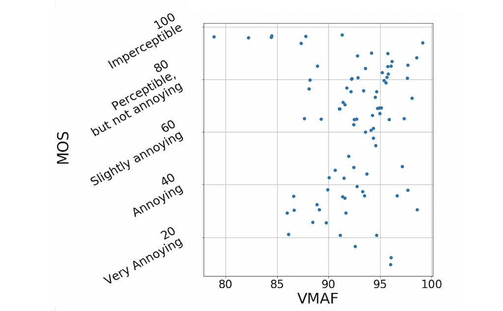
According to usual metrics, the videos in the experiment with perceptible banding should be mid to high-quality (i.e., PSNR>40dB and VMAF>80). However, the experiment scores show something entirely different, as we’ll see below.

You can’t fix it if you don’t know it’s there

Netflix encodes video at scale. Likewise, video quality is assessed at scale within the encoding pipeline, not by an army of humans rating each video. This is where objective video quality metrics come in, as they automatically provide actionable insights into the actual quality of an encode.

PSNR has been the primary video quality metric for decades: it is based on the average pixel distance of the encoded video to the source video. In the case of banding, this distance is tiny compared to its perceptual impact. Consequently, there is little information about banding in the PSNR numbers. The data from the subjective experiment confirms this lack of correlation between PSNR and MOS:

Another video quality metric is VMAF, which Netflix jointly developed with several collaborators and open-sourced on Github. VMAF has become a de facto standard for evaluating the performance of encoding systems and driving encoding optimizations, being a crucial factor for the quality of Netflix encodes. However, VMAF does not specifically target banding artifacts. It was designed with our streaming use case in mind, in particular, to capture the video quality of movies and shows in the presence of encoding and scaling artifacts. VMAF works exceptionally well in the general case, but, like PSNR, lacks correlation with MOS in the presence of banding:

VMAF, PSNR, and other commonly used video quality metrics don’t detect banding artifacts properly and, if we can’t catch the issue, we cannot take steps to fix it. Ideally, our wish list for a banding detector would include the following items:

  • High correlation with MOS for content distorted with banding artifacts
  • Simple, intuitive, distortion-specific, and based on human visual system principles
  • Consistent performance across the different resolutions, qualities, and bit-depths delivered in our service
  • Robust to dithering, which video pipelines commonly introduce

We didn’t find any algorithm in the literature that fit our purposes. So we set out to develop one.

CAMBI

We hand-crafted in a traditional NNN (non-neural network) way an algorithm to meet our requirements. A white box solution derived from first principles with just a few, visually-motivated, parameters: the contrast-aware multiscale banding index (CAMBI).

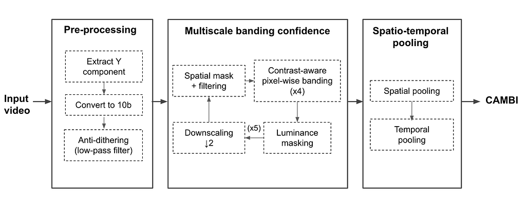
A block diagram describing the steps involved in CAMBI is shown below. CAMBI operates as a no-reference banding detector taking a (distorted) video as an input and producing a banding visibility score as the output. The algorithm extracts pixel-level maps at multiple scales for frames of the encoded video. Subsequently, it combines these maps into a single index motivated by the human contrast sensitivity function (CSF).

Pre-processing

Each input frame goes through up to three pre-processing steps.

The first step extracts the luma component: although chromatic banding exists, like most past works, we assume that most of the banding can be captured in the luma channel. The second step is converting the luma channel to 10-bit (if the input is 8-bit).

Third, we account for the presence of dithering in the frame. Dithering is intentionally applied noise used to randomize quantization error that is shown to reduce banding visibility. To account for both dithered and non-dithered content, we use a 2×2 filter to smoothen the intensity values to replicate the low-pass filtering done by the human visual system.

Multiscale Banding Confidence

We consider banding detection a contrast-detection problem, and hence banding visibility is majorly governed by the CSF. The CSF itself largely depends on the perceived contrast across a step and the spatial frequency of the steps. CAMBI explicitly accounts for the contrast across pixels by looking at the differences in pixel intensity and does this at multiple scales to account for spatial frequency. This is done by calculating pixel-wise banding confidence at different contrasts and scales, each referred to as a CAMBI map for the frame. Banding confidence computation also considers the sensitivity to change in brightness depending on the local brightness. At the end of this process, twenty CAMBI maps are obtained per frame capturing banding across four contrast steps and five scales.

Spatio-Temporal Pooling

CAMBI maps are spatiotemporally pooled to obtain the final banding index. Spatial pooling is done based on the observation that CAMBI maps belong to the initial linear phase of the CSF. First, pooling is applied in the contrast dimension by keeping the maximum weighted contrast for each position. The result is five maps, one per scale. There is an example of such maps further down in this post.

Since regions with the poorest quality dominate the perceived quality of the video, only a percentage of the pixels, those with the most banding, is considered during spatial pooling for the maps at each scale. The resulting scores per scale are linearly combined with CSF-based weights to derive the CAMBI for each frame.

According to our experiments, CAMBI is temporally stable within a single video shot, so a simple average suffices as a temporal pooling mechanism across frames. However, note that this assumption breaks down for videos with multiple shots with different characteristics.

CAMBI agrees with the subjective assessments

Our results show that CAMBI provides a high correlation with MOS while, as illustrated above, VMAF and PSNR have very little correlation. The table reports two correlation coefficients, namely Spearman Rank Order Correlation (SROCC) and Pearson’s Linear Correlation (PLCC):

The following plot visualizes that CAMBI correlates well with subjective scores and that a CAMBI of around 5 is where banding starts to be slightly annoying. Note that, unlike the two quality metrics, CAMBI correlates inversely with MOS: the higher the CAMBI score is, the more perceptible the banding is, and thus the quality is lower.

Staring at the sunset

We use this sunset as an example of banding and how CAMBI scores it. Below we also show the same sunset with fake colors, so bands pop up even more.

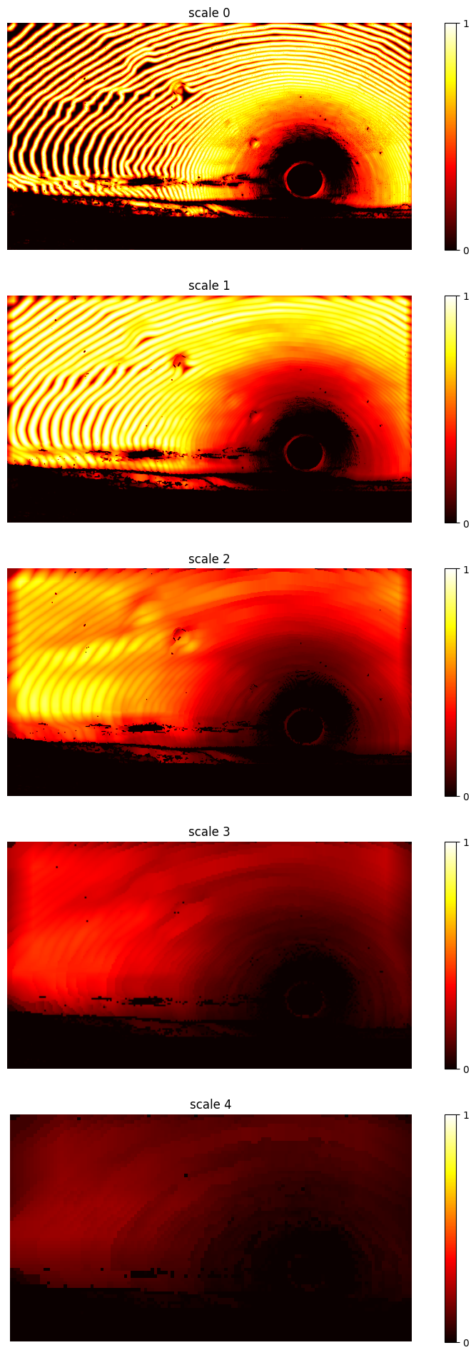
There is no banding on the sea part of the image. In the sky, the size of the bands increases as the distance from the sun increases. The five maps below, one per scale, capture the confidence of banding at different spatial frequencies. These maps are further spatially pooled, accounting for the CSF, giving a CAMBI score of 19 for the frame, which perceptually corresponds to somewhere between ‘annoying’ to ‘very annoying’ banding according to the MOS data.

Open-source and next steps

A banding detection mechanism robust to multiple encoding parameters can help identify the onset of banding in videos and serve as the first step towards its mitigation. In the future, we hope to leverage CAMBI to develop a new version of VMAF that can account for banding artifacts.

We open-sourced CAMBI as a new standalone feature in libvmaf. Similar to VMAF, CAMBI is an organic project expected to be gradually improved over time. We welcome any feedback and contributions.

Acknowledgments

We want to thank Christos Bampis, Kyle Swanson, Andrey Norkin, and Anush Moorthy for the fruitful discussions and all the participants in the subjective tests that made this work possible.


CAMBI, a banding artifact detector was originally published in Netflix TechBlog on Medium, where people are continuing the conversation by highlighting and responding to this story.

Accepting API keys as a query string in Amazon API Gateway

Post Syndicated from Eric Johnson original https://aws.amazon.com/blogs/compute/accepting-api-keys-as-a-query-string-in-amazon-api-gateway/

This post was written by Ronan Prenty, Sr. Solutions Architect and Zac Burns, Cloud Support Engineer & API Gateway SME

Amazon API Gateway is a fully managed service that makes it easier for developers to create, publish, maintain, monitor, and secure APIs at any scale. APIs act as the front door to applications and allow developers to offload tasks like authorization, throttling, caching, and more.

A common feature requested by customers is the ability to track usage for specific users or services through API keys. API Gateway REST APIs support this feature and, for added security, require that the API key resides in a header or an authorizer.

Developers may also need to pass API keys in the query string parameters. Best practices encourage refactoring the requests at the client level to move API keys to the header. However, this may not be possible during the migration.

This blog explains how to build an API Gateway REST API that temporarily accepts API keys as query string parameters. This post helps customers who have APIs that accept API keys as query string parameters and want to migrate to API Gateway with minimal impact on their clients. The post also discusses increasing security by refactoring the client to send API keys as a header instead of a query string.

There is also an example project for you to test and evaluate. This solution uses a custom authorizer AWS Lambda function to extract the API key from the query string parameter and apply it to a usage plan. The sample application uses the AWS Serverless Application Model (AWS SAM) for deployment.

Key concepts

API keys and usage plans

API keys are alphanumeric strings that are distributed to developers to grant access to an API. API Gateway can generate these on your behalf, or you can import them.

Usage plans let you provide API keys to your customers so that you can track and limit their usage. API keys are not a primary authorization mechanism for your APIs. If multiple APIs are associated with a usage plan, a user with a valid API key can access all APIs in that usage plan. We provide numerous options for securing access to your APIs, including resource policies, Lambda authorizers, and Amazon Cognito user pools.

Usage plans define who can access deployed API stages and methods along with metering their usage. Usage plans use API keys to identify who is making requests and apply throttling and quota limits.

How API Gateway handles API keys

API Gateway supports API keys sent as headers in a request. It does not support API keys sent as a query string parameter. API Gateway only accepts requests over HTTPS, which means that the request is encrypted. When sending API keys as query string parameters, there is still a risk that URLs are logged in plaintext by the client sending requests.

API Gateway has two settings to accept API keys:

  1. Header: The request contains the values as the X-API-Key header. API Gateway then validates the key against a usage plan.
  2. Authorizer: The authorizer includes the API key as part of the authorization response. Once API Gateway receives the API key as part of the response, it validates it against a usage plan.

Solution overview

To accept an API key as a query string parameter temporarily, create a custom authorizer using a Lambda function:

Note: the apiKeySource property of your API must be set to Authorizer instead of Header.

Note: the apiKeySource property of your API must be set to Authorizer instead of Header.

  1. The client sends an HTTP request to the API Gateway endpoint with the API key in the query string.
  2. API Gateway sends the request to a REQUEST type custom authorizer
  3. The custom authorizer function extracts the API Key from the payload. It constructs the response object with the API Key as the value for the `usageIdentifierKey` property
  4. The response gets sent back to API Gateway for validation.
  5. API Gateway validates the API key against a usage plan.
  6. If valid, API Gateway passes the request to the backend.

Deploying the solution

Prerequisites

This solution requires no pre-existing AWS resources and deploys everything you need from the template. Deploying the solution requires:

You can find the solution on GitHub using this link.

With the prerequisites completed, deploy the template with the following commands:

git clone https://github.com/aws-samples/amazon-apigateway-accept-apikeys-as-querystring.git
cd amazon-apigateway-accept-apikeys-as-querystring
sam build --use-container
sam deploy --guided

Long term considerations

This temporary solution enables developers to migrate APIs to API Gateway and maintain query string-based API keys. While this solution does work, it does not follow best practices.

In addition to security, there is also a cost factor. Each time the client request contains an API key, the custom authorizer AWS Lambda function will be invoked, increasing the total amount of Lambda invocations you are billed for. To ensure you are billed only for valid requests, you can add an identity source to the custom authorizer meaning that only requests containing this identity source will be sent to the Lambda function. Requests that do not contain this identity source will not be billed by Lambda or API Gateway. Migrating to a header-based API key removes the need for a custom authorizer and the extra Lambda function invocations. You can find out more information on AWS Lambda billing here.

Customer migration process

With this in mind, the structure of the request sent by API clients must change from:

GET /some-endpoint?apiKey=abc123456789

To:

GET /some-endpoint
x-api-key: abc123456789

You can provide clients with a notice period when this temporary solution is operational. After, they must migrate to a new API endpoint using a header to provide the API keys. Once the client migration is complete, they can retire the custom solution.

Developer portal

In addition to migrating API keys to a header-based solution, customers also ask us how to manage customer keys and usage plans. One option is to deploy the API Gateway developer portal.

This portal enables your customers to discover available APIs, browse API documentation, register for API keys, test APIs in the user interface, and monitor their API usage. This portal also allows you to publish non-API Gateway managed APIs by uploading OpenAPI definitions. The serverless developer portal can be customized and branded to suit your organization.

Conclusion

This blog post demonstrates how to use custom authorizers in API Gateway to accept API keys as a query string parameter. It also provides an AWS SAM template to deploy an example application for testing. Finally, it discusses the importance of moving customers to header-based API keys and managing those keys with the developer portal.

For more serverless content, visit Serverless Land.

How Amazon Transportation Service enabled near-real-time event analytics at petabyte scale using AWS Glue with Apache Hudi

Post Syndicated from Madhavan Sriram original https://aws.amazon.com/blogs/big-data/how-amazon-transportation-service-enabled-near-real-time-event-analytics-at-petabyte-scale-using-aws-glue-with-apache-hudi/

This post is co-written with Madhavan Sriram and Diego Menin from Amazon Transportation Services (ATS).

The transportation and logistics industry covers a wide range of services, such as multi-modal transportation, warehousing, fulfillment, freight forwarding, and delivery. At Amazon Transportation Service (ATS), the lifecycle of the shipment is digitally tracked and appended to tens of tracking updates on average. Those tracking updates are vital to kick off events through the shipment operational and billing lifecycle, including delay identification and route optimization. They are also the base for the customer and consumer tracking experience through the different touchpoints.

In this post, we discuss how ATS enabled near-real-time event analytics at petabyte scale using Apache Hudi tables created by AWS Glue Spark jobs.

ATS was looking for ways to securely and cost-efficiently manage and derive analytical insights over petabyte-sized datasets, with data coming in from different sources at different paces, and stored over different storage solutions. You can gain deeper and richer insights when you bring together all your relevant data of all structures and types, from all sources, to analyze.

One of the main challenges that our data engineering team at ATS faced was bringing together all the data arriving in real time, and building a holistic view for our customers and partners. The majority of the orders placed through Amazon, one of the world’s largest online retailers, are operationalized by ATS for the transportation and logistics. ATS provides the business accurate and timely package delivery. ATS operations generate data at petabyte scale, so having the data available at their fingertips provides innumerable opportunities to improve operations through data-driven decision-making.

Apache Hudi is an open-source data management framework used to simplify incremental data processing and data pipeline development. This framework more efficiently manages business requirements like data lifecycles and improves data quality. Hudi enables you to manage data at the record level in Amazon Simple Storage Service (Amazon S3) data lakes to simplify change data capture (CDC) and streaming data ingestion at petabyte scale, and helps handle data privacy use cases requiring record-level updates and deletes.

Solution overview

One of the biggest challenges ATS faced was handling data at petabyte scale with the need for constant inserts, updates, and deletes with minimal time delay, which reflects real business scenarios and package movement to downstream data consumers.

Their traditional data warehouses couldn’t scale to the size of the data nor the frequency of data ingestion. They needed to scale to hundreds of GBs of data across multiple data ingestion sources in order to derive near-real-time data for downstream consumers to use for data analytics that powered business-critical reports, dashboards, and visualizations. The data is also used for training machine learning models with overall service level agreements (SLAs) of 15 minutes for data ingestion and processing.

In this post, we show how we ingest data in real time in the order of hundreds of GBs per hour and run inserts, updates, and deletes on a petabyte-scale data lake using Apache Hudi tables loaded using AWS Glue Spark jobs and other AWS server-less services including AWS Lambda, Amazon Kinesis Data Firehose, and Amazon DynamoDB. AWS ProServe, working closely with ATS, built a data lake comprising of Apache Hudi tables on Amazon S3 created and populated using AWS Glue. A data pipeline was created that supports inserts, updates, and deletes at petabyte scale on the Apache Hudi tables using AWS Glue. To support real-time time ingestion, ATS also implemented a real-time data ingestion pipeline based on Kinesis Data Firehose, DynamoDB, and Amazon DynamoDB Streams.

To tackle the challenges we discussed, we decided to follow the “Divide et Impera” approach, and define two separate workstreams:

  • Stream-based – We ingested data from four different data sources and 11 datasets, and performed some initial data transformation and joins steps, honoring a time window that may vary from 3 hours to 2 weeks across all workloads. The event rate might go up to thousands of events per second, and events might have duplicates, arrive late, or not be in the correct order. Our objective was to understand in real time the transit status of a given package or truck, capture the current status of ATS operations in real time, and extend the current stream-based solution to offload and supplement the current extract, transform, and load (ETL) solution, based on Amazon Redshift.
  • Data lake – We wanted the ability to store petabytes of data and allow for merges between historical data (petabytes) with newly ingested data. The data retention policy extends to up to 5 years, which brings increased costs and reduces performance significantly. Our team requires access to near-real-time data (less than 15 minutes) from stream-based ingestion, with full GDPR compliance. Our objective was to merge stream-based ingested data files to derive a holistic view of the dataset at a certain point in time, with an SLA of under 15 minutes. Data lineage capabilities would also be nice to have.

Stream-based solution

The following diagram illustrates the architecture of our stream-based solution.

The flow of the solution is as follows:

  1. Data is ingested from various sources in separate Firehose data streams, collected for up to 15 minutes and stored in S3 buckets.
  2. Upon the arrival of every new file in Amazon S3, a Lambda function is triggered to insert data into a DynamoDB table associated with a specific data source or datasets.
  3. With DynamoDB Streams, we trigger a second Lambda function that aggregates data in real time across the different DynamoDB tables by performing real-time DynamoDB table lookups. The ETL window is enforced using DynamoDB item TTL, so data is automatically deleted from the table after the TTL period expires.
  4. After it’s transformed, data is collected in Amazon S3 passing through a Firehose delivery stream and is ready to be ingested into our data lake.

The solution allows us to do the following:

  • Ingest data in parallel, in real time, and at the desired scale from all the data sources
  • Scale on demand, and with minimal human operational overhead; this is achieved using an AWS Serverless technology stack
  • Implement our desired time window on a per-item base, reducing costs and the total amount of data stored
  • Implement ETL using Lambda functions in Python, thereby providing a tighter grasp over expressing the business logic
  • Access data on Amazon S3 before it’s ingested into our data lake, and allow customers and partners to consume data in raw format if needed

The data present in Amazon S3 represents the starting point for a seamless data lake integration.

Data lake ingestion

Moving into our data lake, the following diagram illustrates our architecture for data lake ingestion.

The core implementation in this architecture is the AWS Glue Spark ingestion job for the Hudi table; it represents the entry point for the incremental data processing pipeline.

AWS Glue Spark job runs with a concurrency of 1 and contains the logic for upsert and delete sequentially applied on the Hudi table. The sequencing of delete after upsert in the AWS Glue Spark job ensures, deletes are applied after upsert and the data consistency is maintained even in case of job reruns.

To use Apache Hudi v0.7 on AWS Glue jobs using PySpark, we imported the following libraries in the AWS Glue jobs, extracted locally from the master node of Amazon EMR:

  • hudi-spark-bundle_2.11-0.7.0-amzn-1.jar
  • spark-avro_2.11-2.4.7-amzn-1.jar

We recommend using Glue 3.0 with Hudi 0.9.0 connector rather than importing Hudi v0.7 jar files from EMR, for seamless integration and have more capabilities and features.

Before we insert data the Hudi table, we prepare it for push. To optimize for incremental merge, we take a fixed lookup window based on business use case considerations. We start by reading historical data in a given time window. See the following code:

# HUDI DATA READ
read_options = {
  'hoodie.datasource.query.type': 'snapshot'
}


# HUDI DATAFRAME  created  from target Hudi Table on S3
hudi_df = spark. \
  read. \
  format("hudi"). \
  options(*read_options). \
  load(config['target'] + "////*")

# Read Historical data set, load(basePath) use "/partitionKey=partitionValue" folder structure for Spark auto partition discovery

# input_df is the INCREMENT DATAFRAME created from incrementally ingested data on S3
input_df = spark.read.format("csv"). options(header='true').load(config['incremental_path'])


window_year, window_month, window_day = year_month_day_window()
window_filter_clause = "year >= {} AND month >= {} and day >= {}".format(window_year, window_month, window_day)

# We merge it with the incoming newly available data: 

# Data from Hudi Table on S3, because our use case is global, id is unique else id + partitionPath = unique.
hudi_s3_df = hudi_df.select(col("node_id"),col("container_label"),col(config['sort_key'])).filter(window_filter_clause)

# Perform a left outer join between new data (input_df) and data present in S3 Hudi. (hudi_s3_df)
hudi_join_df = input_df.alias("incomingData").join(hudi_s3_df.alias("S3HudiData"), (input_df.node_id == hudi_s3_df.node_id) & (input_df.container_label == hudi_s3_df.container_label), "leftouter")

# As it's a Left Outer join, there might bew new records which aren't present on S3 Hudi. 

hudi_new_df = hudi_join_df.filter(col("S3HudiData.last_update_row_epoch_seconds").isNull()).drop(col("S3HudiData.node_id")).drop(col("S3HudiData.container_label")).drop(col("S3HudiData.last_update_row_epoch_seconds"))

# As it's a Left Outer join, Select the records where input_df.last_update_time > hudi_s3_df.last_update_time. 

hudi_updated_df = hudi_join_df.filter(col("S3HudiData.last_update_row_epoch_seconds").isNotNull() & (col("incomingData.last_update_row_epoch_seconds") > col("S3HudiData.last_update_row_epoch_seconds"))).drop(col("S3HudiData.node_id")).drop(col("S3HudiData.container_label")).drop(col("S3HudiData.last_update_row_epoch_seconds"))
hudi_final_df = hudi_new_df.union(hudi_updated_df)

#  After we prepare the data to be pushed in the Hudi table, we implement the Hudi table update using the following code:

(hudi_final_df.write.format(HUDI_FORMAT)
.option(TABLE_NAME, config['hudi_table_name'])
.option(RECORDKEY_FIELD_OPT_KEY, config["primary_key"])
.option(PARTITIONPATH_FIELD_OPT_KEY,config["partition_keys"])
.option(KEYGENERATOR_CLASS_OPT_KEY, COMPLEX_KEYGENERATOR_CLASS_OPT_VAL)
.option(PRECOMBINE_FIELD_OPT_KEY, config["sort_key"])
.option(OPERATION_OPT_KEY, UPSERT_OPERATION_OPT_VAL)
.option(UPSERT_PARALLELISM, 1500)
.option('hoodie.payload.ordering.field',config["sort_key"])
.option(PAYLOAD_CLASS_OPT_KEY,'org.apache.hudi.common.model.DefaultHoodieRecordPayload')
.option(HIVE_PARTITION_FIELDS_OPT_KEY, config["partition_keys"])
.option(HIVE_DATABASE_OPT_KEY,config['hudi_database'])
.option(HIVE_TABLE_OPT_KEY,config['hudi_table_name'])
.option(HIVE_SYNC_ENABLED_OPT_KEY,"true")
.option(HIVE_JDBC_SYNC,"false")
.option(HIVE_PARTITION_EXTRACTOR_CLASS_OPT_KEY, MULTIPART_KEYS_EXTRACTOR_CLASS_OPT_VAL)
.option('hoodie.datasource.write.hive_style_partitioning', 'true')
# To switch to Global Bloom index, set the following configuration as GLOBAL_BLOOM.
.option('hoodie.index.type', 'GLOBAL_SIMPLE') 
.option('hoodie.simple.index.update.partition.path', 'true')
.option('hoodie.global.simple.index.parallelism', '500')
.mode("append")
.save(config['target']))

In the preceding code, config is a dictionary that includes all the Apache Hudi configurations. The AWS Glue Data Catalog is automatically synched after Hudi table creation, as part of the Glue job, reflecting the Amazon S3 partition structure. We can now query the data using Amazon Athena or Amazon Redshift Spectrum.

To comply with our strict internal ingestion SLA, we had to dedicate special attention to employing the right Hudi indexes and defining the right table type. For the latter, we analyzed the type of workload. Due to the analytic nature of the datasets and use case, we identified that the right configuration would be to use a COPY_ON_WRITE table, even if that was a compromise on the write performances but enhanced read performance.

For the former, we went through an experimentation phase. We started with a GLOBAL_BLOOM index, identifying an initial non-linear pattern for data writing performances.

Given the randomness and the time window specified for the input data, we have encountered a significant number of false positives, leading to reading the entire dataset back for comparison. Moreover, GLOBAL_BLOOM keeps increasing linearly corresponding to the data size, whereas GLOBAL_SIMPLE doesn’t bring this overhead (with a fixed lookup window) as can be observed in the diagram.

The graph represents the Total Time taken by Glue Hudi job(X-axis) over days (Y axis) as incoming data is merged with the historical data.  leveraging GLOBAL_BLOOM.  The graph in upper half, shows when same data was merged consecutively over days, non-linear time increase was observed. Lower half graph indicates Linear increase with a steep slope when new incoming data was merged with historical data.

GLOBAL_BLOOM wasn’t appropriate for our use case as the historical data spanned back to 5 years, and Glue job will not be able to meet the SLA demands. At this point, we investigated GLOBAL_SIMPLE indexes, reaching the expected performance patterns.

Our data lake solution allows us to do the following:

  • Ingest data files in a petabyte-scale data lake, with a 15-minute ingestion SLA from the moment we receive the data
  • Read the data at Peta Byte scale by leveraging Amazon S3 partitions (created by Glue jobs and mapped to Hudi partition logic) and faster lookups by using Hudi indexes
  • Use Hudi data lineage capabilities
  • Reduce costs for data storage, infrastructure maintenance, and development
  • Manage data governance using AWS Lake Formation, which allows partners and customers to query the data using their own tools, while allowing ATS to retain control over our data

Conclusion

In this post, we highlighted how ATS built a real-time fully serverless data ingestion platform, scaling up to thousands of events per second and merging with petabyte- sized historical data stored in a data lake in near-real time.

We built a petabyte-scale data lake solution based on Apache Hudi and AWS Glue that allows us to share our data within 15 minutes from ingestion with our partners and consumers, while retaining complete control over our data and automatically offloading costs for data consumption. This provides linear performance as data grows over time.

About Amazon Transportation Service

Amazon Transportation Service (ATS) is the middle mile of the transportation network of Amazon, connecting the fulfillment centers at one end and the delivery stations and post offices at the other end. We enable packages that are ordered and packaged from fulfillment centers that traverse across the European continent to be delivered in the final delivery station that does the house-to-house delivery.


About the Authors

Madhavan Sriram is a Manager, Data Science who comes with a wide experience across multiple enterprise organisations in the space of Big Data and Machine Learning technologies. He currently leads the Data Technology and Products team within Amazon Transportation Services (ATS) and builds data-intensive products for the transportation network within Amazon. In his free time, Madhavan enjoys photography and poetry.

Diego Menin is a Senior Data Engineer within the Data Technology and Products team. He comes with a wide experience across startups and enterprises with deep AWS expertise to develop scalable cloud-based data and analytics products. Within Amazon, he is the architect of Amazon’s transportation data lake and working heavily on streaming data and integration mechanisms with downstream applications through the data lake.

Gabriele Cacciola is a Senior Data Architect working for the Professional Service team with Amazon Web Services. Coming from a solid Startup experience, he currently helps enterprise customers across EMEA implement their ideas, innovate using the latest tech and build scalable data and analytics solutions to make critical business decisions. In his free time, Gabriele enjoys football and cooking.

Kunal Gautam is a Senior Big Data Architect at Amazon Web Services. Having experience in building his own Startup and working along with enterprises, he brings a unique perspective to get people, business and technology work in tandem for customers. He is passionate about helping customers in their digital transformation journey and enables them to build scalable data and advance analytics solutions to gain timely insights and make critical business decisions. In his spare time, Kunal enjoys Marathons, Tech Meetups and Meditation retreats.

Bringing Connected Container Management via Cycle

Post Syndicated from Elton Carneiro original https://www.backblaze.com/blog/bringing-connected-container-management-to-backblaze-cycle/

Containers have changed the way development teams build, deploy, and scale their applications. Unfortunately, the adoption of containers often brings with it ever-growing complexity and fragility that leads to developers spending more time managing their deployment rather than developing applications.

Today’s announcement offers developers a path to easier container orchestration. The Cycle and Backblaze B2 Cloud Storage integration enables companies that utilize containers to seamlessly automate and control stateful data across multiple providers—all from one dashboard.

This partnership empowers developers to:

  • Easily deploy containers without dealing with complex solutions like Kubernetes.
  • Unify their application management, including automating or scheduling backups via an API-connected portal.
  • Choose the microservices and technologies they need without compromising on functionality.

Getting started with Cycle and Backblaze is simple:

  1. Create a Cycle account.
  2. Sign up for B2 Cloud Storage and create a bucket and Application Key.
  3. Associate your Backblaze Application Key with your Cycle hub via the Integrations menu.
  4. Utilize the backup settings within a container config.

For more in-depth information on the integration, check out the documentation.

We recently sat down with Jake Warner, Co-founder and CEO of Cycle, to dig a little deeper into the major cloud orchestration challenges today’s developers face. You can find Jake’s responses below, or you can check out a conversation between Jake and Elton Carneiro, Backblaze Director of Partnerships, on Jake’s podcast.

About Cycle

Cycle set out to become the most developer-friendly container orchestration platform. By simplifying the processes around container and infrastructure deployments, Cycle enables developers to spend more time building and less time managing. With automatic platform updates, standardized deployments, a powerful API, and bottleneck crushing automation—the platform empowers organizations to have the capabilities of an elite DevOps team at one-tenth the cost. Founded in 2015, the company is headquartered in Reno, NV. To learn more, please visit https://cycle.io.

A Q&A With Cycle

Q: Give us a background on Cycle and what problem you are trying to solve? What is the problem with existing infrastructure like Kubernetes and/or similar?

A: We believe that cloud orchestration, and more specifically, container orchestration, is broken. Instead of focusing on the most common use cases, too many companies within this space end up chasing a never-ending list of edge cases and features. This lack of focus yields overly complex, messy, and fragile deployments that cause more stress than peace-of-mind.

Cycle takes a bold approach on container orchestration: focus on the 80%. Most companies don’t require, or need, a majority of the features and capabilities that come with platforms like Kubernetes. By staying hyper-focused on where we spend our time, and prioritizing quality over quantity of features, the Cycle platform has become an incredibly stable and powerful foundation for companies of all sizes.

The goal for Cycle is simple: Be the most developer-friendly container platform for businesses.

We believe that developers should be able to easily utilize containers on their own infrastructure without having to deal with the mundane tasks commonly involved with managing infrastructure and orchestration platforms. Cycle makes that a reality.

Q: What are the major challenges developers face today with container orchestration?

Complexity. Most deployments today require piecing together a wide variety of different tools and technologies for even the most basic deployments. Instead of adopting solutions that empower development teams without increasing bloat, too many organizations are chasing hype and increasing their ever-growing pile of technical debt.

Additionally, most of today’s platforms require constant hand-holding. While there are many tools that help reduce the amount of time to get a first deployment online, we see a major drop-off when it comes to “day two operations.” What happens when there’s a new update, or security patch? How often are these updates released? How many developers/DevOps personnel are needed to apply these updates? How much downtime should be expected?

With Cycle, we reduce complexity by providing a single turnkey solution for developers—no extra tools required. Additionally, our platform is built around the idea that everything should be capable of automatically updating. On average, we deploy platform updates to our customer infrastructure once every 10-14 days.

Q: Before announcing our integration, had you implemented Backblaze internally? Could you expand on that?

Absolutely! In the early days of Cycle, we made the decision to standardize and flatten all container images into raw OCI images. This was our way of hedging against different technologies going through hype waves. At the time, Docker was the “top dog” in the container space but there was also CoreOS and a number of others.

In an effort to control as much of the vertical stack as possible, we decided that, beyond flattening images, we should also store the resulting images ourselves. This way, if Docker Hub or another container registry unexpectedly changed their APIs or pricing, our platform and users would be insulated from those changes. As you can see, we put a lot of thought into limiting external variables.

Given the above, we knew that having an infinitely scalable storage solution was critical for the platform. After testing a number of providers, Backblaze B2 was the perfect fit for our needs.

Fast-forward to today, where all base images are stored on Backblaze.

Q: As alluded to above, you’re currently building a customer-facing integration. What’s the new feature? Have customers been asking for this?

We’re excited to announce that Cycle now supports automatic backups for stateful containers. A number of customers have been requesting this feature for a while and we’re thrilled to finally release it.

At Cycle, data ownership is very important to us—our platform was built specifically to empower developers while ensuring they, and their employers, still retain full ownership and control of their data. This automated backups feature is no different. By associating a Backblaze B2 API Key with Cycle, organizations can maintain ownership of their backups.

Q: What sparked the decision to partner and integrate with Backblaze specifically?

While there are a number of reasons this partnership makes a ton of sense, narrowing it down to a top three would be:

Performance: As we were testing different Object Storage providers, Backblaze B2 routinely was one of the most reliable while also offering solid upload and download speeds. We also liked that Backblaze B2 wasn’t overly bloated with features—it had exactly what we needed.

Cost: As Cycle continues to grow, and our storage needs increase, it’s incredibly important to keep costs in check. Beyond predictable and transparent pricing, the base cost per terabyte of data is impressive.

Team: Working with the Backblaze team has been incredible. From our early conversations with Nilay, Backblaze’s VP of Sales, to the expanded conversations with much of the Backblaze team today, everyone has been super eager to help.

Q: Backblaze and Cycle share a similar vision in making life easier for developers. It goes beyond just dollars saved, though that is a bonus, but what is it about “simple” that is so important? Infrastructure of the future?

Good question! There are a number of different ways to answer this, but for the sake of not turning this into an essay, let’s focus purely on what we, the Cycle team, refer to as “think long term.”

Anyone can make a process complex, but it takes a truly focused effort to keep things simple. Rules and guidelines are needed. You need to be able to say “No” to certain feature requests and customer demands. To be able to provide a polished and clean experience, you have to be purposeful in what you’re building. Far too often, companies will chase short term wins while sacrificing long-term gains, but true innovation takes time. In a world where most tech companies are built off venture capital, long-term gambles and innovations are deprioritized.

From the way both Cycle and Backblaze have been funded, to a number of other aspects, we’ve both positioned our companies to take those long term risks and focus on simplifying otherwise complex processes. It’s part of our culture, it’s who we are as teams and organizations.

As we talk about developers, we see a common pattern. Developers always love testing new technologies, they enjoy getting into the weeds and tweaking all of the variables. But, as time goes on, developers shift away from “I want to control every variable” into more of a “I just want something that works and gets out of the way.” This is where Cycle and Backblaze both excel.

Q: What can we look forward to as this partnership matures? Anything exciting on the horizon for Cycle that you’d like to share?

We’re really looking forward to expanding our partnership with Backblaze as the Cycle platform continues to grow. Combining powerful container orchestration with a seamless object storage solution can empower developers to more easily build the next generation of products and services.

While we now host our base container images and customer backups on Backblaze, this is still just the start. We have a number of really exciting features launching in 2022 that’ll further strengthen the partnership between our companies and the value we can provide to developers around the world.
Interested in learning more about the developer solutions available with Backblaze B2 Cloud Storage? Join us, free, for Developer Day on October 21 for announcements, tech talks, lessons, SWAG, and more to help you understand how B2 Cloud Storage can work for you. Register today.

The post Bringing Connected Container Management via Cycle appeared first on Backblaze Blog | Cloud Storage & Cloud Backup.

Recovering Real Faces from Face-Generation ML System

Post Syndicated from Bruce Schneier original https://www.schneier.com/blog/archives/2021/10/recovering-real-faces-from-face-generation-ml-system.html

New paper: “This Person (Probably) Exists. Identity Membership Attacks Against GAN Generated Faces.

Abstract: Recently, generative adversarial networks (GANs) have achieved stunning realism, fooling even human observers. Indeed, the popular tongue-in-cheek website http://thispersondoesnotexist.com, taunts users with GAN generated images that seem too real to believe. On the other hand, GANs do leak information about their training data, as evidenced by membership attacks recently demonstrated in the literature. In this work, we challenge the assumption that GAN faces really are novel creations, by constructing a successful membership attack of a new kind. Unlike previous works, our attack can accurately discern samples sharing the same identity as training samples without being the same samples. We demonstrate the interest of our attack across several popular face datasets and GAN training procedures. Notably, we show that even in the presence of significant dataset diversity, an over represented person can pose a privacy concern.

News article. Slashdot post.

Using JSONPath effectively in AWS Step Functions

Post Syndicated from James Beswick original https://aws.amazon.com/blogs/compute/using-jsonpath-effectively-in-aws-step-functions/

This post is written by Dhiraj Mahapatro, Senior Serverless Specialist SA, Serverless.

AWS Step Functions uses Amazon States Language (ASL), which is a JSON-based, structured language used to define the state machine. ASL uses paths for input and output processing in between states. Paths follow JSONPath syntax.

JSONPath provides the capability to select parts of JSON structures similar to how XPath expressions select nodes of XML documents. Step Functions provides the data flow simulator, which helps in modeling input and output path processing using JSONPath.

This blog post explains how you can effectively use JSONPath in a Step Functions workflow. It shows how you can separate concerns between states by specifically identifying input to and output from each state. It also explains how you can use advanced JSONPath expressions for filtering and mapping JSON content.

Overview

The sample application in this blog is based on a use case in the insurance domain. A new potential customer signs up with an insurance company by creating an account. The customer provides their basic information, and their interests in the types of insurances for shopping later.

The information provided by the potential insurance customer is accepted by the insurance company’s new account application for processing. This application is built using Step Functions, which accepts provided input as a JSON payload and applies the following business logic:

Example application architecture

  1. Verify the identity of the user.
  2. Verify the address of the user.
  3. Approve the new account application if the checks pass.
  4. Upon approval, insert user information into the Amazon DynamoDB Accounts table.
  5. Collect home insurance interests and store in an Amazon SQS queue.
  6. Send email notification to the user about the application approval.
  7. Deny the new account application if the checks fail.
  8. Send an email notification to the user about the application denial.

Deploying the application

Before deploying the solution, you need:

To deploy:

  1. From a terminal window, clone the GitHub repo:
    git clone [email protected]:aws-samples/serverless-account-signup-service.git
  2. Change directory:
    cd ./serverless-account-signup-service
  3. Download and install dependencies:
    sam build
  4. Deploy the application to your AWS account:
    sam deploy --guided
  5. During the guided deployment process, enter a valid email address for the parameter “Email” to receive email notifications.
  6. Once deployed, a confirmation email is sent to the provided email address from SNS. Confirm the subscription by clicking the link in the email.
    Email confirmation

To run the application using the AWS CLI, replace the state machine ARN from the output of deployment steps:

aws stepfunctions start-execution \
  --state-machine-arn <StepFunctionArnHere> \
  --input "{\"data\":{\"firstname\":\"Jane\",\"lastname\":\"Doe\",\"identity\":{\"email\":\"[email protected]\",\"ssn\":\"123-45-6789\"},\"address\":{\"street\":\"123 Main St\",\"city\":\"Columbus\",\"state\":\"OH\",\"zip\":\"43219\"},\"interests\":[{\"category\":\"home\",\"type\":\"own\",\"yearBuilt\":2004},{\"category\":\"auto\",\"type\":\"car\",\"yearBuilt\":2012},{\"category\":\"boat\",\"type\":\"snowmobile\",\"yearBuilt\":2020},{\"category\":\"auto\",\"type\":\"motorcycle\",\"yearBuilt\":2018},{\"category\":\"auto\",\"type\":\"RV\",\"yearBuilt\":2015},{\"category\":\"home\",\"type\":\"business\",\"yearBuilt\":2009}]}}"

Paths in Step Functions

Here is the sample payload structure :

{
  "data": {
    "firstname": "Jane",
    "lastname": "Doe",
    "identity": {
      "email": "[email protected]",
      "ssn": "123-45-6789"
    },
    "address": {
      "street": "123 Main St",
      "city": "Columbus",
      "state": "OH",
      "zip": "43219"
    },
    "interests": [
      {"category": "home", "type": "own", "yearBuilt": 2004},
      {"category": "auto", "type": "car", "yearBuilt": 2012},
      {"category": "boat", "type": "snowmobile", "yearBuilt": 2020},
      {"category": "auto", "type": "motorcycle", "yearBuilt": 2018},
      {"category": "auto", "type": "RV", "yearBuilt": 2015},
      {"category": "home", "type": "business", "yearBuilt": 2009}
    ]
  }
}

The payload has data about the new user (identity and address information) and the user’s interests in the types of insurance.

The Compute Blog post on using data flow simulator elaborates on how to use Step Functions paths. To summarize how paths work:

  1. InputPath – What input does a task need?
  2. Parameters – How does the task need the structure of the input to be?
  3. ResultSelectors – What to choose from the task’s output?
  4. ResultPath – Where to put the chosen output?
  5. OutputPath – What output to send to the next state?

The key idea is that the input of downstream states input depends on the output of previous states. JSONPath expressions help structuring input and output between states.

Using JSONPath inside paths

This is how paths are used in the sample application for each type.

InputPath

The first two main tasks in the Step Functions state machine validate the identity and the address of the user. Since both validations are unrelated, they can work independently by using parallel state.

Each state needs the identity and address information provided by the input payload. There is no requirement to provide interests to those states, so InputPath can help answer “What input does a task need?”.

Inside the Check Identity state:

"InputPath": "$.data.identity"

Inside the Check Address state:

"InputPath": "$.data.address"

Parameters

What should the input of the underlying task look like? Check Identity and Check Address use their respective AWS Lambda functions. When Lambda functions or any other AWS service integration is used as a task, the state machine should follow the request syntax of the corresponding service.

For a Lambda function as a task, the state should provide the FunctionName and an optional Payload as parameters. For the Check Identity state, the parameters section looks like:

"Parameters": {
    "FunctionName": "${CheckIdentityFunctionArn}",
    "Payload.$": "$"
}

Here, Payload is the entire identity JSON object provided by InputPath.

ResultSelector

Once the Check Identity task is invoked, the Lambda function successfully validates the user’s identity and responds with an approval response:

{
  "ExecutedVersion": "$LATEST",
  "Payload": {
    "statusCode": "200",
    "body": "{\"approved\": true,\"message\": \"identity validation passed\"}"
  },
  "SdkHttpMetadata": {
    "HttpHeaders": {
      "Connection": "keep-alive",
      "Content-Length": "43",
      "Content-Type": "application/json",
      "Date": "Thu, 16 Apr 2020 17:58:15 GMT",
      "X-Amz-Executed-Version": "$LATEST",
      "x-amzn-Remapped-Content-Length": "0",
      "x-amzn-RequestId": "88fba57b-adbe-467f-abf4-daca36fc9028",
      "X-Amzn-Trace-Id": "root=1-5e989cb6-90039fd8971196666b022b62;sampled=0"
    },
    "HttpStatusCode": 200
  },
  "SdkResponseMetadata": {
    "RequestId": "88fba57b-adbe-467f-abf4-daca36fc9028"
  },
  "StatusCode": 200
}

The identity validation approval must be provided to the downstream states for additional processing. However, the downstream states only need the Payload.body from the preceding JSON.

You can use a combination of intrinsic function and ResultSelector to choose attributes from the task’s output:

"ResultSelector": {
  "identity.$": "States.StringToJson($.Payload.body)"
}

ResultSelector takes the JSON string $.Payload.body and applies States.StringToJson to convert the string to JSON store in a new attribute named identity:

"identity": {
    "approved": true,
    "message": "identity validation passed"
}

When Check Identity and Check Address states finish their work and exit, the step output from each state is captured as a JSON array. This JSON array is the step output of the parallel state. Reconcile the results from the JSON array using the ResultSelector that is available in parallel state.

"ResultSelector": {
    "identityResult.$": "$[0].result.identity",
    "addressResult.$": "$[1].result.address"
}

ResultPath

After ResultSelector, where should the identity result go to in the initial payload? The downstream states need access to the actual input payload in addition to the results from the previous state. ResultPath provides the mechanism to extend the initial payload to add results from the previous state.

ResultPath: "$.result" informs the state machine that any result selected from the task output (actual output if none specified) should go under result JSON attribute and result should get added to the incoming payload. The output from ResultPath looks like:

{
  "data": {
    "firstname": "Jane",
    "lastname": "Doe",
    "identity": {
      "email": "[email protected]",
      "ssn": "123-45-6789"
    },
    "address": {
      "street": "123 Main St",
      "city": "Columbus",
      "state": "OH",
      "zip": "43219"
    },
    "interests": [
      {"category":"home", "type":"own", "yearBuilt":2004},
      {"category":"auto", "type":"car", "yearBuilt":2012},
      {"category":"boat", "type":"snowmobile","yearBuilt":2020},
      {"category":"auto", "type":"motorcycle","yearBuilt":2018},
      {"category":"auto", "type":"RV", "yearBuilt":2015},
      {"category":"home", "type":"business", "yearBuilt":2009}
    ]
  },
  "result": {
    "identity": {
      "approved": true,
      "message": "identity validation passed"
    }
  }
}

The preceding JSON has results from an operation but also the incoming payload is intact for business logic in downstream states.

This pattern ensures that the previous state keeps the payload hydrated for the next state. Use these combinations of paths across all states to make sure that each state has all the information needed.

As with the parallel state’s ResultSelector, an appropriate ResultPath is needed to hold both the results from Check Identity and Check Address to get the below results JSON object added to the payload:

"results": {
  "addressResult": {
    "approved": true,
    "message": "address validation passed"
  },
  "identityResult": {
    "approved": true,
    "message": "identity validation passed"
  }
}

With this approach for all of the downstream states, the input payload is still intact and the state machine has collected results from each state in results.

OutputPath

To return results from the state machine, ideally you do not send back the input payload to the caller of the Step Functions workflow. You can use OutputPath to select a portion of the state output as an end result. OutputPath determines what output to send to the next state.

In the sample application, the last states (Approved Message and Deny Message) defined OutputPath as:

“OutputPath”: “$.results”

The output from the state machine is:

{
  "addressResult": {
    "approved": true,
    "message": "address validation passed"
  },
  "identityResult": {
    "approved": true,
    "message": "identity validation passed"
  },
  "accountAddition": {
    "statusCode": 200
  },
  "homeInsuranceInterests": {
    "statusCode": 200
  },
  "sendApprovedNotification": {
    "statusCode": 200
  }
}

This response strategy is also effective when using a Synchronous Express Workflow for this business logic.

Advanced JSONPath

You can declaratively use advanced JSONPath expressions to apply logic without writing imperative code in utility functions.

Let’s focus on the interests that the new customer has asked for in the input payload. The Step Functions state machine has a state that focuses on interests in the “home” insurance category. Once the new account application is approved and added to the database successfully, the application captures home insurance interests. It adds home-related detail in an HomeInterestsQueue SQS queue and transitions to the Approved Message state.

The interests JSON array has the information about insurance interests. An effective way to get home-related details is to filter out the interests array based on the category “home”. You can try this in data flow simulator:

Data flow simulator

You can apply additional filter expressions to filter data according to your use case. To learn more, visit the the data flow simulator blog.

Inside the state machine JSON, the Home Insurance Interests task has:

"InputPath": "$..interests[?(@.category==home)]"

It uses advanced JSONPath with $.. notation and [?(@.category==home)] filters.

Using advanced expressions on JSONPath is not limited to home insurance interests and can be extended to other categories and business logic.

Cleanup

To delete the sample application, use the latest version of the AWS SAM CLI and run:

sam delete

Conclusion

This post uses a sample application to highlight effective use of JSONPath and data filtering strategies that can be used in Step Functions.

JSONPath provides the flexibility to work on JSON objects and arrays inside the Step Functions states machine by reducing the amount of utility code. It allows developers to build state machines by separating concerns for states’ input and output data. Advanced JSONPath expressions help writing declarative filtering logic without needing imperative utility code, optimizing cost, and performance.

For more serverless learning resources, visit Serverless Land.

[$] A viable solution for Python concurrency

Post Syndicated from original https://lwn.net/Articles/872869/rss

Concerns over the performance of programs written in Python are often
overstated — for some use cases, at least. But there is no getting around
the problem imposed by the infamous global interpreter lock (GIL), which
severely limits the concurrency of multi-threaded Python code. Various
efforts to remove the GIL have been made
over the years, but none have come anywhere near the point where they would
be considered for inclusion into the CPython interpreter. Now, though, Sam
Gross has entered
the arena
with a proof-of-concept implementation that may solve the
problem for real.

Plasma 25th Anniversary Edition released

Post Syndicated from original https://lwn.net/Articles/872952/rss

The KDE project is celebrating its 25th anniversary with a special release
of the Plasma desktop.

This time around, Plasma renews its looks and, not only do you get
a new wallpaper, but also a gust of fresh air from an updated
theme: Breeze – Blue Ocean. The new Breeze theme makes KDE apps and
tools not only more attractive, but also easier to use both on the
desktop and your phone and tablet.

Of course, looks are not the only you can expect from Plasma 25AE:
extra speed, increased reliability and new features have also found
their way into the app launcher, the software manager, the Wayland
implementation, and most other Plasma tools and utilities.

Lots of details can be found in the
changelog
.

The collective thoughts of the interwebz