Tag Archives: Amazon Elastic Kubernetes Service

Field Notes: Running a Stateful Java Service on Amazon EKS

Post Syndicated from Tom Cheung original https://aws.amazon.com/blogs/architecture/field-notes-running-a-stateful-java-service-on-amazon-eks/

This post was co-authored  by Tom Cheung, Cloud Infrastructure Architect, AWS Professional Services and Bastian Klein, Solutions Architect at AWS.

Containerization helps to create secure and reproducible runtime environments for applications. Container orchestrators help to run containerized applications by providing extended deployment and scaling capabilities, among others. Because of this, many organizations are installing such systems as a platform to run their applications on. Organizations often start their container adaption with new workloads that are well suited for the way how orchestrators manage containers.

After they gained their first experiences with containers, organizations start migrating their existing applications to the same container platform to simplify the infrastructure landscape and unify their deployment mechanisms.  Migrations come with some challenges, as the applications were not designed to run in a container environment. Many of the existing applications work in a stateful manner. They are persisting files to the local storage and make use of stateful sessions. Both requirements need to be met for the application to properly work in the container environment.

This blog post shows how to run a stateful Java service on Amazon EKS with the focus on how to handle stateful sessions You will learn how to deploy the service to Amazon EKS and how to save the session state in an Amazon ElastiCache Redis database. There is a GitHub Repository that provides all sources that are mentioned in this article. It contains AWS CloudFormation templates that will setup the required infrastructure, as well as the Java application code along with the Kubernetes resource templates.

The Java code used in this blog post and the GitHub Repository are based on a Blog Post from Java In Use: Spring Boot + Session Management Example Using Redis. Our thanks for this content contributed under the MIT-0 license to the Java In Use author.

Overview of architecture

Kubernetes is a popular Open Source container orchestrator that is widely used. Amazon EKS is the managed Kubernetes offering by AWS and used in this example to run the Java application. Amazon EKS manages the Control Plane for you and gives you the freedom to choose between self-managed nodes, managed nodes or AWS Fargate to run your compute.

The following architecture diagram shows the setup that is used for this article.

Container reference architecture


  • There is a VPC composed of three public subnets, three subnets used for the application and three subnets reserved for the database.
  • For this application, there is an Amazon ElastiCache Redis database that stores the user sessions and state.
  • The Amazon EKS Cluster is created with a Managed Node Group containing three t3.micro instances per default. Those instances run the three Java containers.
  • To be able to access the website that is running inside the containers, Elastic Load Balancing is set up inside the public subnets.
  • The Elastic Load Balancing (Classic Load Balancer) is not part of the CloudFormation templates, but will automatically be created by Amazon EKS, when the application is deployed.

Walkthrough

Here are the high-level steps in this post:

  • Deploy the infrastructure to your AWS Account
  • Inspect Java application code
  • Inspect Kubernetes resource templates
  • Containerization of the Java application
  • Deploy containers to the Amazon EKS Cluster
  • Testing and verification

Prerequisites

If you do not want to set this up on your local machine, you can use AWS Cloud9.

Deploying the infrastructure

To deploy the infrastructure, you first need to clone the Github repository.

git clone https://github.com/aws-samples/amazon-eks-example-for-stateful-java-service.git

This repository contains a set of CloudFormation Templates that set up the required infrastructure outlined in the architecture diagram. This repository also contains a deployment script deploy.sh that issues all the necessary CLI commands. The script has one required argument -p that reflects the aws cli profile that should be used. Review the Named Profiles documentation to set up a profile before continuing.

If the profile is already present, the deployment can be started using the following command:

./deploy.sh -p <profile name>

The creation of the infrastructure will roughly take 30 minutes.

The below table shows all configurable parameters of the CloudFormation template:

parameter name table

This template is initiating several steps to deploy the infrastructure. First, it validates all CloudFormation templates. If the validation was successful, an Amazon S3 Bucket is created and the CloudFormation Templates are uploaded there. This is necessary because nested stacks are used. Afterwards the deployment of the main stack is initiated. This will automatically trigger the creation of all nested stacks.

Java application code

The following code is a Java web application implemented using Spring Boot. The application will persist session data at Amazon ElastiCache Redis, which enables the app to become stateless. This is a crucial part of the migration, because it allows you to use Kubernetes horizontal scaling features with Kubernetes resources like Deployments, without the need to use sticky load balancer sessions.

This is the Java ElastiCache Redis implementation by Spring Data Redis and Spring Boot. It allows you to configure the host and port of the deployed Redis instance. Because this is environment-specific information, it is not configured in the properties file It is injected as environment variables during runtime.

/java-microservice-on-eks/src/main/java/com/amazon/aws/Config.java

@Configuration
@ConfigurationProperties("spring.redis")
public class Config {

    private String host;
    private Integer port;


    public String getHost() {
        return host;
    }

    public void setHost(String host) {
        this.host = host;
    }

    public Integer getPort() {
        return port;
    }

    public void setPort(Integer port) {
        this.port = port;
    }

    @Bean
    public LettuceConnectionFactory redisConnectionFactory() {

        return new LettuceConnectionFactory(new RedisStandaloneConfiguration(this.host, this.port));
    }

}


Containerization of Java application

/java-microservice-on-eks/Dockerfile

FROM openjdk:8-jdk-alpine

MAINTAINER Tom Cheung <email address>, Bastian Klein<email address>
VOLUME /tmp
VOLUME /target

RUN addgroup -S spring && adduser -S spring -G spring
USER spring:spring
ARG DEPENDENCY=target/dependency
COPY ${DEPENDENCY}/BOOT-INF/lib /app/lib
COPY ${DEPENDENCY}/META-INF /app/META-INF
COPY ${DEPENDENCY}/BOOT-INF/classes /app
COPY ${DEPENDENCY}/org /app/org

ENTRYPOINT ["java","-Djava.security.egd=file:/dev/./urandom","-cp","app:app/lib/*", "com/amazon/aws/SpringBootSessionApplication"]


This is the Dockerfile to build the container image for the Java application. OpenJDK 8 is used as the base container image. Because of the way Docker images are built, this sample explicitly does not use a so-called ‘fat jar’. Therefore, you have separate image layers for the dependencies and the application code. By leveraging the Docker caching mechanism, optimized build and deploy times can be achieved.

Kubernetes Resources

After reviewing the application specifics, we will now see which Kubernetes Resources are required to run the application.

Kubernetes uses the concept of config maps to store configurations as a resource within the cluster. This allows you to define key value pairs that will be stored within the cluster and which are accessible from other resources.

/java-microservice-on-eks/k8s-resources/config-map.yaml

apiVersion: v1
kind: ConfigMap
metadata:
  name: java-ms
  namespace: default
data:
  host: "***.***.0001.euc1.cache.amazonaws.com"
  port: "6379"

In this case, the config map is used to store the connection information for the created Redis database.

To be able to run the application, Kubernetes Deployments are used in this example. Deployments take care to maintain the state of the application (e.g. number of replicas) with additional deployment capabilities (e.g. rolling deployments).

/java-microservice-on-eks/k8s-resources/deployment.yaml

apiVersion: apps/v1
kind: Deployment
metadata:
  name: java-ms
  # labels so that we can bind a Service to this Pod
  labels:
    app: java-ms
spec:
  replicas: 3
  selector:
    matchLabels:
      app: java-ms
  template:
    metadata:
      labels:
        app: java-ms
    spec:
      containers:
      - name: java-ms
        image: bastianklein/java-ms:1.2
        imagePullPolicy: Always
        resources:
          requests:
            cpu: "500m" #half the CPU free: 0.5 Core
            memory: "256Mi"
          limits:
            cpu: "1000m" #max 1.0 Core
            memory: "512Mi"
        env:
          - name: SPRING_REDIS_HOST
            valueFrom:
              configMapKeyRef:
                name: java-ms
                key: host
          - name: SPRING_REDIS_PORT
            valueFrom:
              configMapKeyRef:
                name: java-ms
                key: port
        ports:
        - containerPort: 8080
          name: http
          protocol: TCP

Deployments are also the place for you to use the configurations stored in config maps and map them to environment variables. The respective configuration can be found under “env”. This setup relies on the Spring Boot feature that is able to read environment variables and write them into the according system properties.

Now that the containers are running, you need to be able to access those containers as a whole from within the cluster, but also from the internet. To be able to route traffic cluster internally Kubernetes has a resource called Service. Kubernetes Services get a Cluster internal IP and DNS name assigned that can be used to access all containers that belong to that Service. Traffic will, by default, be distributed evenly across all replicas.

/java-microservice-on-eks/k8s-resources/service.yaml

apiVersion: v1
kind: Service
metadata:
  name: java-ms
spec:
  type: LoadBalancer
  ports:
    - protocol: TCP
      port: 80 # Port for LB, AWS ELB allow port 80 only  
      targetPort: 8080 # Port for Target Endpoint
  selector:
    app: java-ms
    

The “selector“ defines which Pods belong to the services. It has to match the labels assigned to the pods. The labels are assigned in the “metadata” section in the deployment.

Deploy the Java service to Amazon EKS

Before the deployment can start, there are some steps required to initialize your local environment:

  1. Update the local kubeconfig to configure the kubectl with the created cluster
  2. Update the k8s-resources/config-map.yaml to the created Redis Database Address
  3. Build and package the Java Service
  4. Build and push the Docker image
  5. Update the k8s-resources/deployment.yaml to use the newly created image

These steps can be automatically executed using the init.sh script located in the repository. The script needs following parameter:

  1.  -u – Docker Hub User Name
  2.  -r – Repository Name
  3.  -t – Docker image version tag

A sample invocation looks like this: ./init.sh -u bastianklein -r java-ms -t 1.2

This information is used to concatenate the full docker repository string. In the preceding example this would resolve to bastianklein/java-ms:1.2, which will automatically be pushed to your Docker Hub repository. If you are not yet logged in to docker on the command line execute docker login and follow the displayed steps before executing the init.sh script.

As everything is set up, it is time to deploy the Java service. The below list of commands first deploys all Kubernetes resources and then lists pods and services.

kubectl apply -f k8s-resources/

This will output:

configmap/java-ms created
deployment.apps/java-ms created
service/java-ms created


Now, list the freshly created pods by issuing kubectl get pods.

NAME                                                READY       STATUS                             RESTARTS   AGE

java-ms-69664cc654-7xzkh   0/1     ContainerCreating   0          1s

java-ms-69664cc654-b9lxb   0/1     ContainerCreating   0          1s


Let’s also review the created service kubectl get svc.

NAME            TYPE                   CLUSTER-IP         EXTERNAL-IP                                                        PORT(S)                   AGE            SELECTOR

java-ms          LoadBalancer    172.20.83.176         ***-***.eu-central-1.elb.amazonaws.com         80:32300/TCP       33s               app=java-ms

kubernetes     ClusterIP            172.20.0.1               <none>                                                                      443/TCP                 2d1h            <none>


What we can see here is that the Service with name java-ms has an External-IP assigned to it. This is the DNS Name of the Classic Loadbalancer that is created behind the scenes. If you open that URL, you should see the Website (this might take a few minutes for the ELB to be provisioned).

Testing and verification

The webpage that opens should look similar to the following screenshot. In the text field you can enter text that is saved on clicking the “Save Message” button. This text will be listed in the “Messages” as shown in the following screenshot. These messages are saved as session data and now persists at Amazon ElastiCache Redis.

screenboot session example

By destroying the session, you will lose the saved messages.

Cleaning up

To avoid incurring future charges, you should delete all created resources after you are finished with testing. The repository contains a destroy.sh script. This script takes care to delete all deployed resources.

The script requires one parameter -p that requires the aws cli profile name that should be used: ./destroy.sh -p <profile name>

Conclusion

This post showed you the end-to-end setup of a stateful Java service running on Amazon EKS. The service is made scalable by saving the user sessions and the according session data in a Redis database. This solution requires changing the application code, and there are situations where this is not an option. By using StatefulSets as Kubernetes Resource in combination with an Application Load Balancer and sticky sessions, the goal of replicating the service can still be achieved.

We chose to use a Kubernetes Service in combination with a Classic Load Balancer. For a production workload, managing incoming traffic with a Kubernetes Ingress and an Application Load Balancer might be the better option. If you want to know more about Kubernetes Ingress with Amazon EKS, visit our Application Load Balancing on Amazon EKS documentation.

Field Notes provides hands-on technical guidance from AWS Solutions Architects, consultants, and technical account managers, based on their experiences in the field solving real-world business problems for customers.

Zurich Spain: Managing millions of documents with AWS

Post Syndicated from Miguel Guillot original https://aws.amazon.com/blogs/architecture/zurich-spain-managing-millions-of-documents-with-aws/

This post was cowritten with Oscar Gali, Head of Technology and Architecture for GI in Zurich, Spain

About Zurich Spain

Zurich Spain is part of Zurich Insurance Group (Zurich), known for its financial soundness and solvency. With more than 135 years of history and over 2,000 employees, it is a leading company in the Spanish insurance market.

Introduction

Enterprise Content Management (ECM) is a key capability for business operations in Insurance, due to the number of documents that must be managed every day. In our digital world, managing and storing business documents and images (such as policies or claims) in a secure, available, scalable, and performant platform is critical.

Zurich Spain decided to use AWS to streamline management of their underlying infrastructure, in addition to the pay-as-you-go pricing model and advanced analytics services. All of these service features create a huge advantage for the company.

The challenge

Zurich Spain was managing all documents for non-life insurance on an on-premises proprietary solution. This was based on an ECM market standard product and specific storage infrastructure. That solution over time had several pain points: cost, scalability, and flexibility. This platform has become obsolete and was an obstacle for covering future analytical needs.

After considering different alternatives, Zurich Spain decided to base their new ECM platform on AWS, leveraging many of the managed services. AWS Managed Services helps to reduce your operational overhead and risk. AWS Managed Services automates common activities, such as change requests, monitoring, patch management, security, and backup services. It provides full lifecycle services to provision, run, and support your infrastructure.

Although the architecture design was clear, the challenge was huge. Zurich Spain had to integrate all the existing business applications with the new ECM platform. Concurrently, the company needed to migrate up to 150 million documents including metadata, in less than 6 months.

The Platform

Functionally, features provided by ECM are:

ECM Features

ECM Features

  • Authentication: every request must come from an authenticated user (OpenID Connect JWT).
  • Authorization: on every request, appropriate user permissions are validated.
  • Documentation Services: exposed API that allows interaction with documents (CRUD). For example:
    • The ability to Ingest a document either synchronously (attaching the document to the request) or asynchronously (providing a link to the requester that can be used to attach a document when required).
    • Upload operation stores documents onto Amazon Simple Storage Service (S3) and its metadata, which is saved using Amazon DocumentDB.
    • Documents Retrieve, similarly to the upload operation, can be obtained either synchronously or asynchronously. The latter provides a link to be used to download the document within a time range.
    • ECM has been developed to give the users the ability to search among all the documents uploaded into it.
  • Metadata: every document has technical and business metadata. This gives Zurich Spain the ability to enrich every single document with all the information that is relevant for their business, for example: Customers, Author, Date of creation.
  • Record Management: policies to manage documents lifecycle.
  • Audit: every transaction is logged into the system.
  • Observability: capabilities to monitor and operate all services involved: logging, performance metrics and transactions traceability.

The Architecture

The ECM platform uses AWS services such as Amazon S3 to store documents. In addition, it uses Amazon DocumentDB to store document metadata and audit trail.

The rationale for choosing these services was:

  • Amazon S3 delivers strong read-after-write consistency automatically for all applications, without changes to performance or availability. With strong consistency, Amazon S3 simplifies the migration of on-premises analytics workloads by removing the need to update applications. This reduces costs by removing the need for extra infrastructure to provide strong consistency.
  • Amazon DocumentDB is a NoSQL document-oriented database where its schema flexibility accommodates the different metadata needs. It was key to design the index strategy in advance to ensure the right query performance, considering the volume of data.

A microservices layer has been built on top to provide the right services for the business applications. These include access control, storing or retrieving documents, metadata, and more.

These microservices are built using Thunder, the internal framework and technology stack for digital applications of Zurich Spain. Thunder leverages AWS and provides a K8s environment based on Amazon Elastic Kubernetes Service (Amazon EKS) for microservice deployment.

Zurich Spain Architecture

Figure 2 – Zurich Spain Architecture

Zurich Spain uses AWS Direct Connect to connect from their data center to AWS. With AWS Direct Connect, Zurich Spain can connect to all their AWS resources in an AWS Region. They can transfer their business-critical data directly from their data center into and from AWS. This enables them to bypass their internet service provider and remove network congestion.

Amazon EKS gives Zurich Spain the flexibility to start, run, and scale Kubernetes applications in the AWS Cloud or on-premises. Amazon EKS is helping Zurich Spain to provide highly available and secure clusters while automating key tasks such as patching, node provisioning, and updates. Zurich Spain is also using Amazon Elastic Container Registry (Amazon ECR) to store, manage, share, and deploy container images and artifacts across their environment.

Some interesting metrics of the migration and platform:

  • Volume: 150+ millions (25 TB) of documents migrated
  • Duration: migration took 4 months due to the limited extraction throughput of the old platform
  • Activity: 50,000+ documents are ingested and 25,000+ retrieved daily
  • Average response time:
    • 550 ms to upload a document
    • 300 ms for retrieving a document hosted in the platform

Conclusion

Zurich Spain successfully replaced a market standard ECM product with a new flexible, highly available, and scalable ECM. This resulted in a 65% run cost reduction, improved performance, and enablement of AWS analytical services.

In addition, Zurich Spain has taken advantage of many benefits that AWS brings to their customers. They’ve demonstrated that Thunder, the new internal framework developed using AWS technology, provides fast application development with secure and frequent deployments.

Running cost optimized Spark workloads on Kubernetes using EC2 Spot Instances

Post Syndicated from Emma White original https://aws.amazon.com/blogs/compute/running-cost-optimized-spark-workloads-on-kubernetes-using-ec2-spot-instances/

This post is written by Kinnar Sen, Senior Solutions Architect, EC2 Spot 

Apache Spark is an open-source, distributed processing system used for big data workloads. It provides API operations to perform multiple tasks such as streaming, extract transform load (ETL), query, machine learning (ML), and graph processing. Spark supports four different types of cluster managers (Spark standalone, Apache Mesos, Hadoop YARN, and Kubernetes), which are responsible for scheduling and allocation of resources in the cluster. Spark can run with native Kubernetes support since 2018 (Spark 2.3). AWS customers that have already chosen Kubernetes as their container orchestration tool can also choose to run Spark applications in Kubernetes, increasing the effectiveness of their operations and compute resources.

In this post, I illustrate the deployment of scalable, resilient, and cost optimized Spark application using Kubernetes via Amazon Elastic Kubernetes Service (Amazon EKS) and Amazon EC2 Spot Instances. Learn how to save money on big data workloads by implementing this solution.

Overview

Amazon EC2 Spot Instances

Amazon EC2 Spot Instances let you take advantage of unused EC2 capacity in the AWS Cloud. Spot Instances are available at up to a 90% discount compared to On-Demand Instance prices. Capacity pools are a group of EC2 instances that belong to particular instance family, size, and Availability Zone (AZ). If EC2 needs capacity back for On-Demand Instance usage, Spot Instances can be interrupted by EC2 with a two-minute notification. There are many graceful ways to handle the interruption to ensure that the application is well architected for resilience and fault tolerance. This can be automated via the application and/or infrastructure deployments. Spot Instances are ideal for stateless, fault tolerant, loosely coupled and flexible workloads that can handle interruptions.

Amazon Elastic Kubernetes Service

Amazon EKS is a fully managed Kubernetes service that makes it easy for you to run Kubernetes on AWS without needing to install, operate, and maintain your own Kubernetes control plane. It provides a highly available and scalable managed control plane. It also provides managed worker nodes, which let you create, update, or terminate shut down worker nodes for your cluster with a single command. It is a great choice for deploying flexible and fault tolerant containerized applications. Amazon EKS supports creating and managing Amazon EC2 Spot Instances using Amazon EKS-managed node groups following Spot best practices. This enables you to take advantage of the steep savings and scale that Spot Instances provide for interruptible workloads running in your Kubernetes cluster. Using EKS-managed node groups with Spot Instances requires less operational effort compared to using self-managed nodes. In addition to launching Spot Instances in managed node groups, it is possible to specify multiple instance types in EKS managed node groups. You can find more in this blog.

Apache Spark and Kubernetes

When a spark application is submitted to the Kubernetes cluster the following happens:

  • A Spark driver is created.
  • The driver and the run within pods.
  • The Spark driver then requests for executors, which are scheduled to run within pods. The executors are managed by the driver.
  • The application is launched and once it completes, the executor pods are cleaned up. The driver pod persists the logs and remains in a completed state until the pod is cleared by garbage collection or manually removed. The driver in a completed stage does not consume any memory or compute resources.

Spark Deployment on Kubernetes Cluster

When a spark application runs on clusters managed by Kubernetes, the native Kubernetes scheduler is used. It is possible to schedule the driver/executor pods on a subset of available nodes. The applications can be launched either by a vanilla ‘spark submit’, a workflow orchestrator like Apache Airflow or the spark operator. I use vanilla ‘spark submit’ in this blog. is also able to schedule Spark applications on EKS clusters as described in this launch blog, but Amazon EMR on EKS is out of scope for this post.

Cost optimization

For any organization running big data workloads there are three key requirements: scalability, performance, and low cost. As the size of data increases, there is demand for more compute capacity and the total cost of ownership increases. It is critical to optimize the cost of big data applications. Big Data frameworks (in this case, Spark) are distributed to manage and process high volumes of data. These frameworks are designed for failure, can run on machines with different configurations, and are inherently resilient and flexible.

If Spark deploys on Kubernetes, the executor pods can be scheduled on EC2 Spot Instances and driver pods on On-Demand Instances. This reduces the overall cost of deployment – Spot Instances can save up to 90% over On-Demand Instance prices. This also enables faster results by scaling out executors running on Spot Instances. Spot Instances, by design, can be interrupted when EC2 needs the capacity back. If a driver pod is running on a Spot Instance, which is interrupted then the application fails and the application must be re-submitted. To avoid this situation, the driver pod can be scheduled on On-Demand Instances only. This adds a layer of resiliency to the Spark application running on Kubernetes. To cost optimize the deployment, all the executor pods are scheduled on Spot Instances as that’s where the bulk of compute happens. Spark’s inherent resiliency has the driver launch new executors to replace the ones that fail due to Spot interruptions.

There are a couple of key points to note here.

  • The idea is to start with minimum number of nodes for both On-Demand and Spot Instances (one each) and then auto-scale usingCluster Autoscaler and EC2 Auto Scaling  Cluster Autoscaler for AWS provides integration with Auto Scaling groups. If there are not sufficient resources, the driver and executor pods go into pending state. The Cluster Autoscaler detects pods in pending state and scales worker nodes within the identified Auto Scaling group in the cluster using EC2 Auto Scaling.
  • The scaling for On-Demand and Spot nodes is exclusive of one another. So, if multiple applications are launched the driver and executor pods can be scheduled in different node groups independently per the resource requirements. This helps reduce job failures due to lack of resources for the driver, thus adding to the overall resiliency of the system.
  • Using EKS Managed node groups
    • This requires significantly less operational effort compared to using self-managed nodegroup and enables:
      • Auto enforcement of Spot best practices like Capacity Optimized allocation strategy, Capacity Rebalancing and use multiple instances types.
      • Proactive replacement of Spot nodes using rebalance notifications.
      • Managed draining of Spot nodes via re-balance recommendations.
    • The nodes are auto-labeled so that the pods can be scheduled with NodeAffinity.
      • eks.amazonaws.com/capacityType: SPOT
      • eks.amazonaws.com/capacityType: ON_DEMAND

Now that you understand the products and best practices of used in this tutorial, let’s get started.

Tutorial: running Spark in EKS managed node groups with Spot Instances

In this tutorial, I review steps, which help you launch cost optimized and resilient Spark jobs inside Kubernetes clusters running on EKS. I launch a word-count application counting the words from an Amazon Customer Review dataset and write the output to an Amazon S3 folder. To run the Spark workload on Kubernetes, make sure you have eksctl and kubectl installed on your computer or on an AWS Cloud9 environment. You can run this by using an AWS IAM user or role that has the AdministratorAccess policy attached to it, or check the minimum required permissions for using eksctl. The spot node groups in the Amazon EKS cluster can be launched both in a managed or a self-managed way, in this post I use the former. The config files for this tutorial can be found here. The job is finally launched in cluster mode.

Create Amazon S3 Access Policy

First, I must create an Amazon S3 access policy to allow the Spark application to read/write from Amazon S3. Amazon S3 Access is provisioned by attaching the policy by ARN to the node groups. This associates Amazon S3 access to the NodeInstanceRole and, hence, the node groups then have access to Amazon S3. Download the Amazon S3 policy file from here and modify the <<output folder>> to an Amazon S3 bucket you created. Run the following to create the policy. Note the ARN.

aws iam create-policy --policy-name spark-s3-policy --policy-document file://spark-s3.json

Cluster and node groups deployment

Create an EKS cluster using the following command:

eksctl create cluster –name= sparkonk8 --node-private-networking  --without-nodegroup --asg-access –region=<<AWS Region>>

The cluster takes approximately 15 minutes to launch.

Create the nodegroup using the nodeGroup config file. Replace the <<Policy ARN>> string using the ARN string from the previous step.

eksctl create nodegroup -f managedNodeGroups.yml

Scheduling driver/executor pods

The driver and executor pods can be assigned to nodes using affinity. PodTemplates can be used to configure the detail, which is not supported by Spark launch configuration by default. This feature is available from Spark 3.0.0, requiredDuringScheduling node affinity is used to schedule the driver and executor jobs. Sample podTemplates have been uploaded here.

Launching a Spark application

Create a service account. The spark driver pod uses the service account to create and watch executor pods using Kubernetes API server.

kubectl create serviceaccount spark
kubectl create clusterrolebinding spark-role --clusterrole='edit'  --serviceaccount=default:spark --namespace=default

Download the Cluster Autoscaler and edit it to add the cluster-name. 

curl -LO https://raw.githubusercontent.com/kubernetes/autoscaler/master/cluster-autoscaler/cloudprovider/aws/examples/cluster-autoscaler-autodiscover.yaml

Install the Cluster AutoScaler using the following command:

kubectl apply -f cluster-autoscaler-autodiscover.yaml

Get the details of Kubernetes master to get the head URL.

kubectl cluster-info 

command output

Use the following instructions to build the docker image.

Download the application file (script.py) from here and upload into the Amazon S3 bucket created.

Download the pod template files from here. Submit the application.

bin/spark-submit \
--master k8s://<<MASTER URL>> \
--deploy-mode cluster \
--name 'Job Name' \
--conf spark.eventLog.dir=s3a:// <<S3 BUCKET>>/logs \
--conf spark.eventLog.enabled=true \
--conf spark.history.fs.inProgressOptimization.enabled=true \
--conf spark.history.fs.update.interval=5s \
--conf spark.kubernetes.container.image=<<ECR Spark Docker Image>> \
--conf spark.kubernetes.container.image.pullPolicy=IfNotPresent \
--conf spark.kubernetes.driver.podTemplateFile='../driver_pod_template.yml' \
--conf spark.kubernetes.executor.podTemplateFile='../executor_pod_template.yml' \
--conf spark.kubernetes.authenticate.driver.serviceAccountName=spark \
--conf spark.dynamicAllocation.enabled=true \
--conf spark.dynamicAllocation.shuffleTracking.enabled=true \
--conf spark.dynamicAllocation.maxExecutors=100 \
--conf spark.dynamicAllocation.executorAllocationRatio=0.33 \
--conf spark.dynamicAllocation.sustainedSchedulerBacklogTimeout=30 \
--conf spark.dynamicAllocation.executorIdleTimeout=60s \
--conf spark.driver.memory=8g \
--conf spark.kubernetes.driver.request.cores=2 \
--conf spark.kubernetes.driver.limit.cores=4 \
--conf spark.executor.memory=8g \
--conf spark.kubernetes.executor.request.cores=2 \
--conf spark.kubernetes.executor.limit.cores=4 \
--conf spark.hadoop.fs.s3a.impl=org.apache.hadoop.fs.s3a.S3AFileSystem \
--conf spark.hadoop.fs.s3a.connection.ssl.enabled=false \
--conf spark.hadoop.fs.s3a.fast.upload=true \
s3a://<<S3 BUCKET>>/script.py \
s3a://<<S3 BUCKET>>/output 

A couple of key points to note here

  • podTemplateFile is used here, which enables scheduling of the driver pods to On-Demand Instances and executor pods to Spot Instances.
  • Spark provides a mechanism to allocate dynamically resources dynamically based on workloads. In the latest release of Spark (3.0.0), dynamicAllocation can be used with Kubernetes cluster manager. The executors that do not store, active, shuffled files can be removed to free up the resources. DynamicAllocation works well in tandem with Cluster Autoscaler for resource allocation and optimizes resource for jobs. We are using dynamicAllocation here to enable optimized resource sharing.
  • The application file and output are both in Amazon S3.

Output Files in S3

  • Spark Event logs are redirected to Amazon S3. Spark on Kubernetes creates local temporary files for logs and removes them once the application completes. The logs are redirected to Amazon S3 and Spark History Server can be used to analyze the logs. Note, you can create more instrumentation using tools like Prometheus and Grafana to monitor and manage the cluster.

Spark History Server + Dynamic Allocation

Observations

EC2 Spot Interruptions

The following diagram and log screenshot details from Spark History server showcases the behavior of a Spark application in case of an EC2 Spot interruption.

Four Spark applications launched in parallel in a cluster and one of the Spot nodes was interrupted. A couple of executor pods were terminated shut down in three of the four applications, but due to the resilient nature of Spark new executors were launched and the applications finished almost around the same time.
The Spark Driver identified the shut down executors, which handled the shuffle files and relaunched the tasks running on those executors.
Spark jobs

The Spark Driver identified the shut down executors, which handled the shuffle files and relaunched the tasks running on those executors.

Dynamic Allocation

Dynamic Allocation works with the caveat that it is an experimental feature.

dynamic allocation

Cost Optimization

Cost Optimization is achieved in several different ways from this tutorial.

  • Use of 100% Spot Instances for the Spark executors
  • Use of dynamicAllocation along with cluster autoscaler does make optimized use of resources and hence save cost
  • With the deployment of one driver and executor nodes to begin with and then scaling up on demand reduces the waste of a continuously running cluster

Cluster Autoscaling

Cluster Autoscaling is triggered as it is designed when there are pending (Spark executor) pods.

The Cluster Autoscaler logs can be fetched by:

kubectl logs -f deployment/cluster-autoscaler -n kube-system —tail=10  

Cluster Autoscaler Logs 

Cleanup

If you are trying out the tutorial, run the following steps to make sure that you don’t encounter unwanted costs.

Delete the EKS cluster and the nodegroups with the following command:

eksctl delete cluster --name sparkonk8

Delete the Amazon S3 Access Policy with the following command:

aws iam delete-policy --policy-arn <<POLICY ARN>>

Delete the Amazon S3 Output Bucket with the following command:

aws s3 rb --force s3://<<S3_BUCKET>>

Conclusion

In this blog, I demonstrated how you can run Spark workloads on a Kubernetes Cluster using Spot Instances, achieving scalability, resilience, and cost optimization. To cost optimize your Spark based big data workloads, consider running spark application using Kubernetes and EC2 Spot Instances.


Field Notes: Managing an Amazon EKS Cluster Using AWS CDK and Cloud Resource Property Manager

Post Syndicated from Raj Seshadri original https://aws.amazon.com/blogs/architecture/field-notes-managing-an-amazon-eks-cluster-using-aws-cdk-and-cloud-resource-property-manager/

This post is contributed by Bill Kerr and Raj Seshadri

For most customers, infrastructure is hardly done with CI/CD in mind. However, Infrastructure as Code (IaC) should be a best practice for DevOps professionals when they provision cloud-native assets. Microservice apps that run inside an Amazon EKS cluster often use CI/CD, so why not the cluster and related cloud infrastructure as well?

This blog demonstrates how to spin up cluster infrastructure managed by CI/CD using CDK code and Cloud Resource Property Manager (CRPM) property files. Managing cloud resources is ultimately about managing properties, such as instance type, cluster version, etc. CRPM helps you organize all those properties by importing bite-sized YAML files, which are stitched together with CDK. It keeps all of what’s good about YAML in YAML, and places all of the logic in beautiful CDK code. Ultimately this improves productivity and reliability as it eliminates manual configuration steps.

Architecture Overview

In this architecture, we create a six node Amazon EKS cluster. The Amazon EKS cluster has a node group spanning private subnets across two Availability Zones. There are two public subnets in different Availability Zones available for use with an Elastic Load Balancer.

EKS architecture diagram

Changes to the primary (master) branch triggers a pipeline, which creates CloudFormation change sets for an Amazon EKS stack and a CI/CD stack. After human approval, the change sets are initiated (executed).

CloudFormation sets

Prerequisites

Get ready to deploy the CloudFormation stacks with CDK

First, to get started with CDK you spin up a AWS Cloud9 environment, which gives you a code editor and terminal that runs in a web browser. Using AWS Cloud9 is optional but highly recommended since it speeds up the process.

Create a new AWS Cloud9 environment

  1. Navigate to Cloud9 in the AWS Management Console.
  2. Select Create environment.
  3. Enter a name and select Next step.
  4. Leave the default settings and select Next step again.
  5. Select Create environment.

Download and install the dependencies and demo CDK application

In a terminal, let’s review the code used in this article and install it.

# Install TypeScript globally for CDK
npm i -g typescript

# If you are running these commands in Cloud9 or already have CDK installed, then
skip this command
npm i -g aws-cdk

# Clone the demo CDK application code
git clone https://github.com/shi/crpm-eks

# Change directory
cd crpm-eks

# Install the CDK application
npm i

Create the IAM service role

When creating an EKS cluster, the IAM role that was used to create the cluster is also the role that will be able to access it afterwards.

Deploy the CloudFormation stack containing the role

Let’s deploy a CloudFormation stack containing a role that will later be used to create the cluster and also to access it. While we’re at it, let’s also add our current user ARN to the role, so that we can assume the role.

# Deploy the EKS management role CloudFormation stack
cdk deploy role --parameters AwsArn=$(aws sts get-caller-identity --query Arn --output text)

# It will ask, "Do you wish to deploy these changes (y/n)?"
# Enter y and then press enter to continue deploying

Notice the Outputs section that shows up in the CDK deploy results, which contains the role name and the role ARN. You will need to copy and paste the role ARN (ex. arn:aws:iam::123456789012:role/eks-role-us-east-
1) from your Outputs when deploying the next stack.

Example Outputs:
role.ExportsOutputRefRoleFF41A16F = eks-role-us-east-1
role.ExportsOutputFnGetAttRoleArnED52E3F8 = arn:aws:iam::123456789012:role/eksrole-us-east-1

Create the EKS cluster

Now that we have a role created, it’s time to create the cluster using that role.

Deploy the stack containing the EKS cluster in a new VPC

Expect it to take over 20 minutes for this stack to deploy.

# Deploy the EKS cluster CloudFormation stack
# REPLACE ROLE_ARN WITH ROLE ARN FROM OUTPUTS IN ROLE STACK CREATED ABOVE
cdk deploy eks -r ROLE_ARN

# It will ask, "Do you wish to deploy these changes (y/n)?"
# Enter y and then press enter to continue deploying

Notice the Outputs section, which contains the cluster name (ex. eks-demo) and the UpdateKubeConfigCommand. The UpdateKubeConfigCommand is useful if you already have kubectl installed somewhere and would rather use your own to interact with the cluster instead of using Cloud9’s.

Example Outputs:
eks.ExportsOutputRefControlPlane70FAD3FA = eks-demo
eks.UpdateKubeConfigCommand = aws eks update-kubeconfig --name eks-demo --region
us-east-1 --role-arn arn:aws:iam::123456789012:role/eks-role-us-east-1
eks.FargatePodExecutionRoleArn = arn:aws:iam::123456789012:role/eks-cluster-
FargatePodExecutionRole-U495K4DHW93M

Navigate to this page in the AWS console if you would like to see your cluster, which is now ready to use.

Configure kubectl with access to cluster

If you are following along in Cloud9, you can skip configuring kubectl.

If you prefer to use kubectl installed somewhere else, now would be a good time to configure access to the newly created cluster by running the UpdateKubeConfigCommand mentioned in the Outputs section above. It requires that you have the AWS CLI installed and configured.

aws eks update-kubeconfig --name eks-demo --region us-east-1 --role-arn
arn:aws:iam::123456789012:role/eks-role-us-east-1

# Test access to cluster
kubectl get nodes

Leveraging Infrastructure CI/CD

Now that the VPC and cluster have been created, it’s time to turn on CI/CD. This will create a cloned copy of github.com/shi/crpm-eks in CodeCommit. Then, an AWS CloudWatch Events rule will start watching the CodeCommit repo for changes and triggering a CI/CD pipeline that builds and validates CloudFormation templates, and executes CloudFormation change sets.

Deploy the stack containing the code repo and pipeline

# Deploy the CI/CD CloudFormation stack
cdk deploy cicd

# It will ask, "Do you wish to deploy these changes (y/n)?"
# Enter y and then press enter to continue deploying

Notice the Outputs section, which contains the CodeCommit repo name (ex. eks-ci-cd). This is where the code now lives that is being watched for changes.

Example Outputs:
cicd.ExportsOutputFnGetAttLambdaRoleArn275A39EB =
arn:aws:iam::774461968944:role/eks-ci-cd-LambdaRole-6PFYXVSLTQ0D
cicd.ExportsOutputFnGetAttRepositoryNameC88C868A = eks-ci-cd

Review the pipeline for the first time

Navigate to this page in the AWS console and you should see a new pipeline in progress. The pipeline is automatically run for the first time when it is created, even though no changes have been made yet. Open the pipeline and scroll down to the Review stage. You’ll see that two change sets were created in parallel (one for the EKS stack and the other for the CI/CD stack).

CICD image

  • Select Review to open an approval popup where you can enter a comment.
  • Select Reject or Approve. Following the Review button, the blue link to the left of Fetch: Initial commit by AWS CodeCommit can be selected to see the infrastructure code changes that triggered the pipeline.

review screen

Go ahead and approve it.

Clone the new AWS CodeCommit repo

Now that the golden source that is being watched for changes lives in a AWS CodeCommit repo, we need to clone that repo and get rid of the repo we’ve been using up to this point.

If you are following along in AWS Cloud9, you can skip cloning the new repo because you are just going to discard the old AWS Cloud9 environment and start using a new one.

Now would be a good time to clone the newly created repo mentioned in the preceding Outputs section Next, delete the old repo that was cloned from GitHub at the beginning of this blog. You can visit this repository to get the clone URL for the repo.

Review this documentation for help with accessing your private AWS CodeCommit repo using HTTPS.

Review this documentation for help with accessing your repo using SSH.

# Clone the CDK application code (this URL assumes the us-east-1 region)
git clone https://git-codecommit.us-east-1.amazonaws.com/v1/repos/eks-ci-cd

# Change directory
cd eks-ci-cd

# Install the CDK application
npm i

# Remove the old repo
rm -rf ../crpm-eks

Deploy the stack containing the Cloud9 IDE with kubectl and CodeCommit repo

If you are NOT using Cloud9, you can skip this section.

To make life easy, let’s create another Cloud9 environment that has kubectl preconfigured and ready to use, and also has the new CodeCommit repo checked out and ready to edit.

# Deploy the IDE CloudFormation stack
cdk deploy ide

Configuring the new Cloud9 environment

Although kubectl and the code are now ready to use, we still have to manually configure Cloud9 to stop using AWS managed temporary credentials in order for kubectl to be able to access the cluster with the management role. Here’s how to do that and test kubectl:

1. Navigate to this page in the AWS console.
2. In Your environments, select Open IDE for the newly created environment (possibly named eks-ide).
3. Once opened, navigate at the top to AWS Cloud9 -> Preferences.
4. Expand AWS SETTINGS, and under Credentials, disable AWS managed temporary credentials by selecting the toggle button. Then, close the Preferences tab.
5. In a terminal in Cloud9, enter aws configure. Then, answer the questions by leaving them set to None and pressing enter, except for Default region name. Set the Default region name to the current region that you created everything in. The output should look similar to:

AWS Access Key ID [None]:
AWS Secret Access Key [None]:
Default region name [None]: us-east-1
Default output format [None]:

6. Test the environment

kubectl get nodes

If everything is working properly, you should see two nodes appear in the output similar to:

NAME                           STATUS ROLES  AGE   VERSION
ip-192-168-102-69.ec2.internal Ready  <none> 4h50m v1.17.11-ekscfdc40
ip-192-168-69-2.ec2.internal   Ready  <none> 4h50m v1.17.11-ekscfdc40

You can use kubectl from this IDE to control the cluster. When you close the IDE browser window, the Cloud9 environment will automatically shutdown after 30 minutes and remain offline until the next time you reopen it from the AWS console. So, it’s a cheap way to have a kubectl terminal ready when needed.

Delete the old Cloud9 environment

If you have been following along using Cloud9 the whole time, then you should have two Cloud9 environments running at this point (one that was used to initially create everything from code in GitHub, and one that is now ready to edit the CodeCommit repo and control the cluster with kubectl). It’s now a good time to delete the old Cloud9 environment.

  1. Navigate to this page in the AWS console.
  2. In Your environments, select the radio button for the old environment (you named it when creating it) and select Delete.
  3. In the popup, enter the word Delete and select Delete.

Now you should be down to having just one AWS Cloud9 environment that was created when you deployed the ide stack.

Trigger the pipeline to change the infrastructure

Now that we have a cluster up and running that’s defined in code stored in a AWS CodeCommit repo, it’s time to make some changes:

  • We’ll commit and push the changes, which will trigger the pipeline to update the infrastructure.
  • We’ll go ahead and make one change to the cluster nodegroup and another change to the actual CI/CD build process, so that both the eks-cluster stack as well as the eks-ci-cd stack get changed.

1.     In the code that was checked out from AWS CodeCommit, open up res/compute/eks/nodegroup/props.yaml. At the bottom of the file, try changing minSize from 1 to 4, desiredSize from 2 to 6, and maxSize from 3 to 6 as seen in the following screenshot. Then, save the file and close it. The res (resource) directory is your well organized collection of resource properties files.

AWS Cloud9 screenshot

2.     Next, open up res/developer-tools/codebuild/project/props.yaml and find where it contains computeType: ‘BUILD_GENERAL1_SMALL’. Try changing BUILD_GENERAL1_SMALL to BUILD_GENERAL1_MEDIUM. Then, save the file and close it.

3.     Commit and push the changes in a terminal.

cd eks-ci-cd
git add .
git commit -m "Increase nodegroup scaling config sizes and use larger build
environment"
git push

4.     Visit https://console.aws.amazon.com/codesuite/codepipeline/pipelines in the AWS console and you should see your pipeline in progress.

5.     Wait for the Review stage to become Pending.

a.       Following the Approve action box, click the blue link to the left of “Fetch: …” to see the infrastructure code changes that triggered the pipeline. You should see the two code changes you committed above.

3.     After reviewing the changes, go back and select Review to open an approval popup.

4.     In the approval popup, enter a comment and select Approve.

5.     Wait for the pipeline to finish the Deploy stage as it executes the two change sets. You can refresh the page until you see it has finished. It should take a few minutes.

6.     To see that the CodeBuild change has been made, scroll up to the Build stage of the pipeline and click on the AWS CodeBuild link as shown in the following screenshot.

AWS Codebuild screenshot

7.     Next,  select the Build details tab, and you should determine that your Compute size has been upgraded to 7 GB memory, 4 vCPUs as shown in the following screenshot.

project config


8.     By this time, the cluster nodegroup sizes are probably updated. You can confirm with kubectl in a terminal.

# Get nodes
kubectl get nodes

If everything is ready, you should see six (desired size) nodes appear in the output similar to:

NAME                            STATUS   ROLES     AGE     VERSION
ip-192-168-102-69.ec2.internal  Ready    <none>    5h42m   v1.17.11-ekscfdc40
ip-192-168-69-2.ec2.internal    Ready    <none>    5h42m   v1.17.11-ekscfdc40
ip-192-168-43-7.ec2.internal    Ready    <none>    10m     v1.17.11-ekscfdc40
ip-192-168-27-14.ec2.internal   Ready    <none>    10m     v1.17.11-ekscfdc40
ip-192-168-36-56.ec2.internal   Ready    <none>    10m     v1.17.11-ekscfdc40
ip-192-168-37-27.ec2.internal   Ready    <none>    10m     v1.17.11-ekscfdc40

Cluster is now manageable by code

You now have a cluster than can be maintained by simply making changes to code! The only resources not being managed by CI/CD in this demo, are the management role, and the optional AWS Cloud9 IDE. You can log into the AWS console and edit the role, adding other Trust relationships in the future, so others can assume the role and access the cluster.

Clean up

Do not try to delete all of the stacks at once! Wait for the stack(s) in a step to finish deleting before moving onto the next step.

1. Navigate to this page in the AWS console.
2. Delete the two IDE stacks first (the ide stack spawned another stack).
3. Delete the ci-cd stack.
4. Delete the cluster stack (this one takes a long time).
5. Delete the role stack.

Additional resources

Cloud Resource Property Manager (CRPM) is an open source project maintained by SHI, hosted on GitHub, and available through npm.

Conclusion

In this blog, we demonstrated how you can spin up an Amazon EKS cluster managed by CI/CD using CDK code and Cloud Resource Property Manager (CRPM) property files. Making updates to this cluster is easy as modifying the property files and updating the AWS CodePipline. Using CRPM can improve productivity and reliability because it eliminates manual configurations steps.

Field Notes provides hands-on technical guidance from AWS Solutions Architects, consultants, and technical account managers, based on their experiences in the field solving real-world business problems for customers
Bill Kerr

Bill Kerr

Bill Kerr is a senior developer at Stratascale who has worked at startup and Fortune 500 companies. He’s the creator of CRPM and he’s a super fan of CDK and cloud infrastructure automation.

New – Amazon EMR on Amazon Elastic Kubernetes Service (EKS)

Post Syndicated from Channy Yun original https://aws.amazon.com/blogs/aws/new-amazon-emr-on-amazon-elastic-kubernetes-service-eks/

Tens of thousands of customers use Amazon EMR to run big data analytics applications on frameworks such as Apache Spark, Hive, HBase, Flink, Hudi, and Presto at scale. EMR automates the provisioning and scaling of these frameworks and optimizes performance with a wide range of EC2 instance types to meet price and performance requirements. Customer are now consolidating compute pools across organizations using Kubernetes. Some customers who manage Apache Spark on Amazon Elastic Kubernetes Service (EKS) themselves want to use EMR to eliminate the heavy lifting of installing and managing their frameworks and integrations with AWS services. In addition, they want to take advantage of the faster runtimes and development and debugging tools that EMR provides.

Today, we are announcing the general availability of Amazon EMR on Amazon EKS, a new deployment option in EMR that allows customers to automate the provisioning and management of open-source big data frameworks on EKS. With EMR on EKS, customers can now run Spark applications alongside other types of applications on the same EKS cluster to improve resource utilization and simplify infrastructure management.

Customers can deploy EMR applications on the same EKS cluster as other types of applications, which allows them to share resources and standardize on a single solution for operating and managing all their applications. Customers get all the same EMR capabilities on EKS that they use on EC2 today, such as access to the latest frameworks, performance optimized runtimes, EMR Notebooks for application development, and Spark user interface for debugging.

Amazon EMR automatically packages the application into a container with the big data framework and provides pre-built connectors for integrating with other AWS services. EMR then deploys the application on the EKS cluster and manages logging and monitoring. With EMR on EKS, you can get 3x faster performance using the performance-optimized Spark runtime included with EMR compared to standard Apache Spark on EKS.

Amazon EMR on EKS – Getting Started
If you already have a EKS cluster where you run Spark jobs, you simply register your existing EKS cluster with EMR using the AWS Management Console, AWS Command Line Interface (CLI) or APIs to deploy your Spark appication.

For exampe, here is a simple CLI command to register your EKS cluster.

$ aws emr create-virtual-cluster \
          --name <virtual_cluster_name> \
          --container-provider '{
             "id": "<eks_cluster_name>",
             "type": "EKS",
             "info": {
                 "eksInfo": {
                     "namespace": "<namespace_name>"
                 }
             } 
         }'

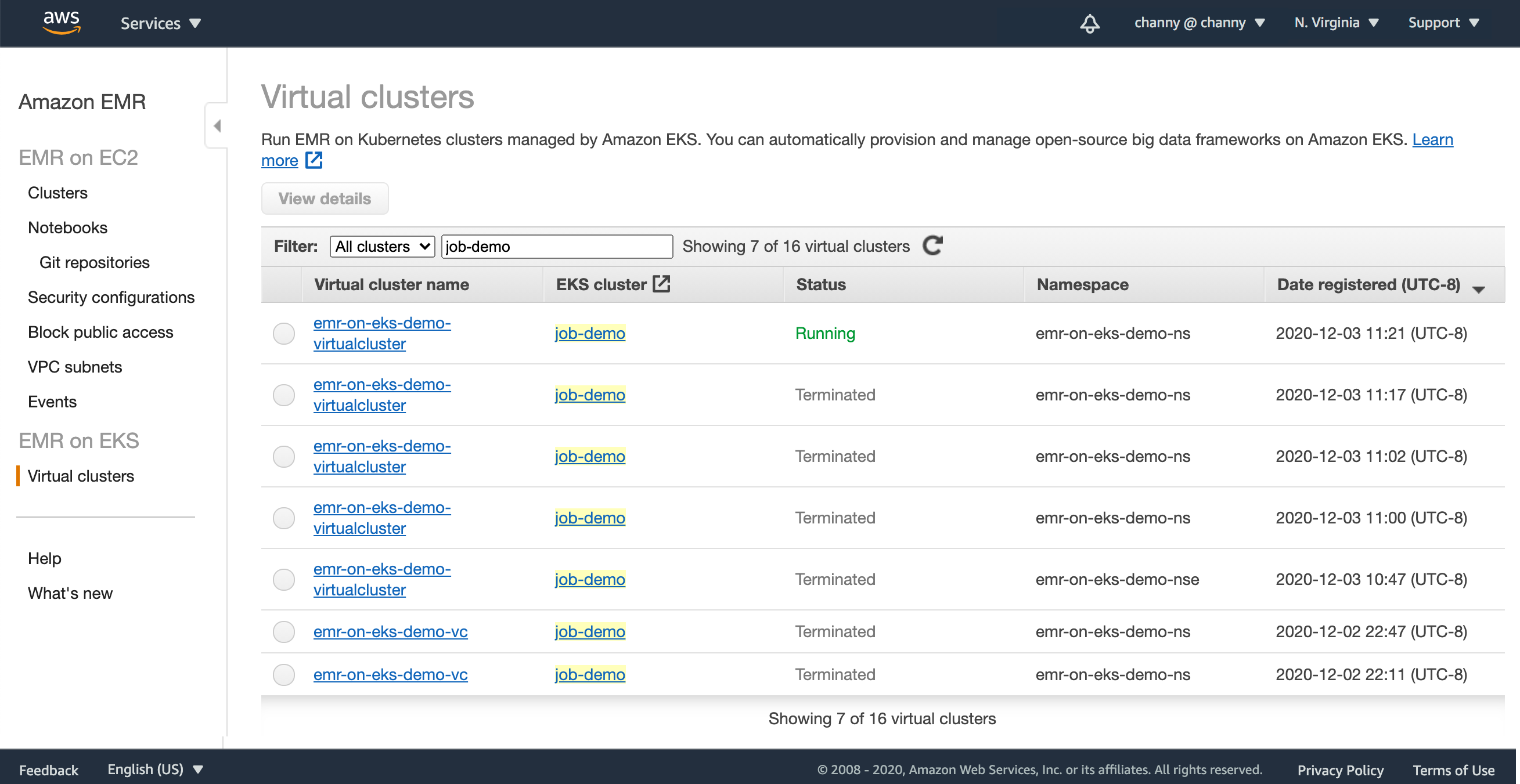
In the EMR Management console, you can see it in the list of virtual clusters.

When Amazon EKS clusters are registered, EMR workloads are deployed to Kubernates nodes and pods to manage application execution and auto-scaling, and sets up managed endpoints so that you can connect notebooks and SQL clients. EMR builds and deploys a performance-optimized runtime for the open source frameworks used in analytics applications.

You can simply start your Spark jobs.

$ aws emr start-job-run \
          --name <job_name> \
          --virtual-cluster-id <cluster_id> \
          --execution-role-arn <IAM_role_arn> \
          --virtual-cluster-id <cluster_id> \
          --release-label <<emr_release_label> \
          --job-driver '{
            "sparkSubmitJobDriver": {
              "entryPoint": <entry_point_location>,
              "entryPointArguments": ["<arguments_list>"],
              "sparkSubmitParameters": <spark_parameters>
            }
       }'

To monitor and debug jobs, you can use inspect logs uploaded to your Amazon CloudWatch and Amazon Simple Storage Service (S3) location configured as part of monitoringConfiguration. You can also use the one-click experience from the console to launch the Spark History Server.

Integration with Amazon EMR Studio

Now you can submit analytics applications using AWS SDKs and AWS CLI, Amazon EMR Studio notebooks, and workflow orchestration services like Apache Airflow. We have developed a new Airflow Operator for Amazon EMR on EKS. You can use this connector with self-managed Airflow or by adding it to the Plugin Location with Amazon Managed Workflows for Apache Airflow.

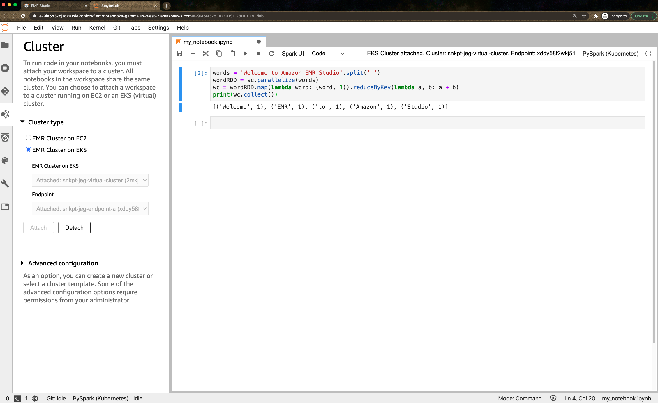
You can also use newly previewed Amazon EMR Studio to perform data analysis and data engineering tasks in a web-based integrated development environment (IDE). Amazon EMR Studio lets you submit notebook code to EMR clusters deployed on EKS using the Studio interface. After seting up one or more managed endpoints to which Studio users can attach a Workspace, EMR Studio can communicate with your virtual cluster.

For EMR Studio preview, there is no additional cost when you create managed endpoints for virtual clusters. To learn more, visit the guide document.

Now Available
Amazon EMR on Amazon EKS is available in US East (N. Virginia), US West (Oregon), and Europe (Ireland) Regions. You can run EMR workloads in AWS Fargate for EKS removing the need to provision and manage infrastructure for pods as a serverless option.

To learn more, visit the documentation. Please send feedback to the AWS forum for Amazon EMR or through your usual AWS support contacts.
Learn all the details about Amazon EMR on Amazon EKS and get started today.

Channy;

Amazon EKS Distro: The Kubernetes Distribution Used by Amazon EKS

Post Syndicated from Martin Beeby original https://aws.amazon.com/blogs/aws/amazon-eks-distro-the-kubernetes-distribution-used-by-amazon-eks/

Our customers have told us that they want to focus on building innovative solutions for their customers, and focus less on the heavy lifting of managing Kubernetes infrastructure. That is why Amazon Elastic Kubernetes Service (EKS) has been so popular; we remove the burden of managing Kubernetes while our customers glean the benefits.

However, not all customers choose to use Amazon EKS. For example, they may have existing infrastructure investments, data residency requirements or compliance obligations that lead them to operate Kubernetes on-premises. Customers in these situations tell us that they spend a lot of effort to track updates, figure out compatible versions of Kubernetes and the complicated matrix of underlying components, test them for compatibility, and keep pace with the Kubernetes release cadence, which can be as frequent as every three to four months. If customers are not able to maintain pace for testing and qualifying new versions, they risk breaking changes, version compatibility issues, and running unsupported versions of Kubernetes lacking critical security patches.

We have learned a lot while providing Amazon EKS at AWS and have developed a deep understanding of how to deliver Kubernetes with operational security, stability, and reliability. Today we are sharing Amazon EKS Distro, which we built using that knowledge.

EKS Distro is a distribution of the same version of Kubernetes deployed by Amazon EKS, which you can use to manually create your own Kubernetes clusters anywhere you choose. EKS Distro provides the installable builds and code of open source Kubernetes used by Amazon EKS, including the dependencies and AWS-maintained patches. Using a choice of cluster creation and management tooling, you can create EKS Distro clusters in AWS on Amazon Elastic Compute Cloud (EC2), in other clouds, and on your on-premises hardware.

EKS Distro includes upstream open source Kubernetes components and third-party tools including configuration database, network, and storage components necessary for cluster creation. They include Kubernetes control plane components (kube-controller-manager, etcd, and CoreDNS) and Kubernetes worker node components (kubelet, CNI plugins, CSI Sidecar images, Metrics Server and AWS-IAM-authenticator).

Building a Cluster
The EKS Distro repository has everything you need to build and create Kubernetes clusters. The repository contains the raw documentation for EKS Distro, and it has been built and published at https://distro.eks.amazonaws.com.

To create a new cluster, I follow this section of the documentation. The guide explains how I can build all of the parts and ultimately deploy a cluster to some EC2 instances on AWS using the open source tool kOps. EKS Distro works with many other tools besides kOps. You can find the details in the partner section of the documentation, and many partners have released blogs today that explain how you can deploy using their tooling.
The guide explains that before I can build my cluster, I need to get several container images. I can get them from the EKS Distro Container repository, download them as a tarball, or build them from scratch. I opt to build my containers from scratch and follow the Build Guide. An hour later, I have managed to create twenty containers and have pushed them into Amazon Elastic Container Registry.

The instructions detail several prerequisites that are required by both the build and deploy stages. I follow the guide and install all of the tools suggested.

Next, as per the guide, I locate the kops.sh script in the development folder of the EKS Distro repository. After running the script, it prompts me to enter a Fully Qualified Domain Name (FQDN). I provide newsblog.thebeebs.net.

This script does several things, including creating an S3 bucket in my account to store artifacts required by kOps. Also, it creates a file called newsblog.thebeebs.net.yaml. I edit this file and replace the container Image URLs with ones that point to my images in Elastic Container Registry.

I continue to follow the guide, which now instructs me to run some kOps commands to create my cluster. These commands use the newsblog.thebeebs.net.yaml file, which was an output of the previous step.

CLUSTER_NAME=newsblog.thebeebs.net
kops create -f ./$CLUSTER_NAME.yaml
kops create secret --name $CLUSTER_NAME sshpublickey admin -i ~/.ssh/id_rsa.pub
kops update cluster $CLUSTER_NAME --yes
kops validate cluster --wait 10m
cat << EOF > aws-iam-authenticator.yaml
apiVersion: v1
kind: ConfigMap
metadata:
  name: aws-iam-authenticator
  namespace: kube-system
  labels:
    k8s-app: aws-iam-authenticator
data:
  config.yaml: |
    clusterID: $CLUSTER_NAME
EOF

One of these commands creates a file called aws-iam-authenticator.yaml. I will apply this file to my kubernetes cluster so that it works correctly with the aws-iam-authenticator.

kubectl apply -f aws-iam-authenticator.yaml

I can now verify that my Kubernetes cluster is using the EKS Distro images by using kubectl to list all of the namespaces.

kubectl get po --all-namespaces -o json | jq -r .items[].spec.containers[].image | sort

Lastly, I delete my cluster by using kOps and issuing a delete command.

kops delete -f ./newsblog.thebeebs.net.yaml --yes

Updates
New versions of EKS Distro will be released soon after we make releases to Amazon EKS. The source code, open source tools, and settings are provided for reproducible builds so you can be assured EKS Distro matches what is deployed by Amazon EKS.

Things to Know
EKS Distro supports the same versions of Kubernetes and point releases that Amazon EKS uses. EKS Distro provides the same upstream versions of Kubernetes and dependencies that operating system vendors have tested and confirmed work with Kubernetes. This means that EKS Distro already works with common operating systems, such as CentOS, Canonical Ubuntu, Red Hat Enterprise Linux, Suse, and more.

Pricing and Support
EKS Distro is an open source project and will be distributed for free. Please collaborate with us on GitHub to make it even better. For example, if you find any issues, please submit them or create a pull request and we will fix them on a best effort basis. Partners will receive support through the Amazon Partner Network program and customers that adopt EKS Distro through partners will receive support from those providers.

What is Coming Next?
In 2021 we will be launching EKS Anywhere, which will provide an installable software package for creating and operating Kubernetes clusters on-premises and automation tooling for cluster lifecycle support, it will enable you to centrally backup, recover, patch, and upgrade your production clusters with minimal disruption. EKS Anywhere creates clusters based on EKS Distro, and so you will have version consistency with Amazon EKS. This version and tooling consistency will reduce support costs, and eliminate the redundant effort of using multiple tools for managing your on-premises and Amazon EKS clusters.

Available Now
EKS Distro is available today for download and you can get the source and builds from GitHub. To help you get started, check out the documentation.

Happy Deploying!

— Martin

re:Invent 2020 – Preannouncements for Tuesday, December 1

Post Syndicated from Jeff Barr original https://aws.amazon.com/blogs/aws/reinvent-2020-preannouncements-for-tuesday-december-1/

Andy Jassy just gave you a hint about some upcoming AWS launches, and I’ll have more to say about them when they are ready. To tide you over until then, here’s a summary of what he pre-announced:

Smaller AWS Outpost Form Factors – We are introducing two new sizes of AWS Outposts, suitable for locations such as branch offices, factories, retail stores, health clinics, hospitals, and cell sites that are space-constrained and need access to low-latency compute capacity. The 1U (rack unit) Outposts server will be equipped with AWS Graviton 2 processors; the 2U Outposts server will be equipped with Intel® processors. Both sizes will be able to run EC2, ECS, and EKS workloads locally, all provisioned and managed by AWS (including automated patching and updates).

Amazon ECS Anywhere – You will soon be able to run Amazon Elastic Container Service (ECS) in your own data center, giving you the power to select and standardize on a single container orchestrator that runs both on-premises and in the cloud. You will have access to the same ECS APIs, and you will be able to manage all of your ECS resources with the same cluster management, workload scheduling, and monitoring tools and utilities. Amazon ECS Anywhere will also make it easy for you to containerize your existing on-premises workloads, run them locally, and then connect them to the AWS Cloud.

Amazon EKS Anywhere – You will also soon be able to run Amazon Elastic Kubernetes Service (EKS) in your own data center, making it easy for you to set up, upgrade, and operate Kubernetes clusters. The default configuration for each new cluster will include logging, monitoring, networking, and storage, all optimized for the environment that will host the cluster. You will be able to spin up clusters on demand, and you will be able to backup, recover, patch, and upgrade production clusters with minimal disruption.

Again, I’ll have more to say about these when they are ready, so stay tuned, and enjoy the rest of AWS re:Invent!

Jeff;

Snowflake: Running Millions of Simulation Tests with Amazon EKS

Post Syndicated from Keith Joelner original https://aws.amazon.com/blogs/architecture/snowflake-running-millions-of-simulation-tests-with-amazon-eks/

This post was co-written with Brian Nutt, Senior Software Engineer and Kao Makino, Principal Performance Engineer, both at Snowflake.

Transactional databases are a key component of any production system. Maintaining data integrity while rows are read and written at a massive scale is a major technical challenge for these types of databases. To ensure their stability, it’s necessary to test many different scenarios and configurations. Simulating as many of these as possible allows engineers to quickly catch defects and build resilience. But the Holy Grail is to accomplish this at scale and within a timeframe that allows your developers to iterate quickly.

Snowflake has been using and advancing FoundationDB (FDB), an open-source, ACID-compliant, distributed key-value store since 2014. FDB, running on Amazon Elastic Cloud Compute (EC2) and Amazon Elastic Block Storage (EBS), has proven to be extremely reliable and is a key part of Snowflake’s cloud services layer architecture. To support its development process of creating high quality and stable software, Snowflake developed Project Joshua, an internal system that leverages Amazon Elastic Kubernetes Service (EKS), Amazon Elastic Container Registry (ECR), Amazon EC2 Spot Instances, and AWS PrivateLink to run over one hundred thousand of validation and regression tests an hour.

About Snowflake

Snowflake is a single, integrated data platform delivered as a service. Built from the ground up for the cloud, Snowflake’s unique multi-cluster shared data architecture delivers the performance, scale, elasticity, and concurrency that today’s organizations require. It features storage, compute, and global services layers that are physically separated but logically integrated. Data workloads scale independently from one another, making it an ideal platform for data warehousing, data lakes, data engineering, data science, modern data sharing, and developing data applications.

Snowflake architecture

Developing a simulation-based testing and validation framework

Snowflake’s cloud services layer is composed of a collection of services that manage virtual warehouses, query optimization, and transactions. This layer relies on rich metadata stored in FDB.

Prior to the creation of the simulation framework, Project Joshua, FDB developers ran tests on their laptops and were limited by the number they could run. Additionally, there was a scheduled nightly job for running further tests.

Joshua at Snowflake

Amazon EKS as the foundation

Snowflake’s platform team decided to use Kubernetes to build Project Joshua. Their focus was on helping engineers run their workloads instead of spending cycles on the management of the control plane. They turned to Amazon EKS to achieve their scalability needs. This was a crucial success criterion for Project Joshua since at any point in time there could be hundreds of nodes running in the cluster. Snowflake utilizes the Kubernetes Cluster Autoscaler to dynamically scale worker nodes in minutes to support a tests-based queue of Joshua’s requests.

With the integration of Amazon EKS and Amazon Virtual Private Cloud (Amazon VPC), Snowflake is able to control access to the required resources. For example: the database that serves Joshua’s test queues is external to the EKS cluster. By using the Amazon VPC CNI plugin, each pod receives an IP address in the VPC and Snowflake can control access to the test queue via security groups.

To achieve its desired performance, Snowflake created its own custom pod scaler, which responds quicker to changes than using a custom metric for pod scheduling.

  • The agent scaler is responsible for monitoring a test queue in the coordination database (which, coincidentally, is also FDB) to schedule Joshua agents. The agent scaler communicates directly with Amazon EKS using the Kubernetes API to schedule tests in parallel.
  • Joshua agents (one agent per pod) are responsible for pulling tests from the test queue, executing, and reporting results. Tests are run one at a time within the EKS Cluster until the test queue is drained.

Achieving scale and cost savings with Amazon EC2 Spot

A Spot Fleet is a collection—or fleet—of Amazon EC2 Spot instances that Joshua uses to make the infrastructure more reliable and cost effective. ​ Spot Fleet is used to reduce the cost of worker nodes by running a variety of instance types.

With Spot Fleet, Snowflake requests a combination of different instance types to help ensure that demand gets fulfilled. These options make Fleet more tolerant of surges in demand for instance types. If a surge occurs it will not significantly affect tasks since Joshua is agnostic to the type of instance and can fall back to a different instance type and still be available.

For reservations, Snowflake uses the capacity-optimized allocation strategy to automatically launch Spot Instances into the most available pools by looking at real-time capacity data and predicting which are the most available. This helps Snowflake quickly switch instances reserved to what is most available in the Spot market, instead of spending time contending for the cheapest instances, at the cost of a potentially higher price.

Overcoming hurdles

Snowflake’s usage of a public container registry posed a scalability challenge. When starting hundreds of worker nodes, each node needs to pull images from the public registry. This can lead to a potential rate limiting issue when all outbound traffic goes through a NAT gateway.

For example, consider 1,000 nodes pulling a 10 GB image. Each pull request requires each node to download the image across the public internet. Some issues that need to be addressed are latency, reliability, and increased costs due to the additional time to download an image for each test. Also, container registries can become unavailable or may rate-limit download requests. Lastly, images are pulled through public internet and other services in the cluster can experience pulling issues.

​For anything more than a minimal workload, a local container registry is needed. If an image is first pulled from the public registry and then pushed to a local registry (cache), it only needs to pull once from the public registry, then all worker nodes benefit from a local pull. That’s why Snowflake decided to replicate images to ECR, a fully managed docker container registry, providing a reliable local registry to store images. Additional benefits for the local registry are that it’s not exclusive to Joshua; all platform components required for Snowflake clusters can be cached in the local ECR Registry. For additional security and performance Snowflake uses AWS PrivateLink to keep all network traffic from ECR to the workers nodes within the AWS network. It also resolved rate-limiting issues from pulling images from a public registry with unauthenticated requests, unblocking other cluster nodes from pulling critical images for operation.

Conclusion

Project Joshua allows Snowflake to enable developers to test more scenarios without having to worry about the management of the infrastructure. ​ Snowflake’s engineers can schedule thousands of test simulations and configurations to catch bugs faster. FDB is a key component of ​the Snowflake stack and Project Joshua helps make FDB more stable and resilient. Additionally, Amazon EC2 Spot has provided non-trivial cost savings to Snowflake vs. running on-demand or buying reserved instances.

If you want to know more about how Snowflake built its high performance data warehouse as a Service on AWS, watch the This is My Architecture video below.

Field Notes: Optimize your Java application for Amazon ECS with Quarkus

Post Syndicated from Sascha Moellering original https://aws.amazon.com/blogs/architecture/field-notes-optimize-your-java-application-for-amazon-ecs-with-quarkus/

In this blog post, I show you an interesting approach to implement a Java-based application and compile it to a native image using Quarkus. This native image is the main application, which is containerized, and runs in an Amazon Elastic Container Service and Amazon Elastic Kubernetes Service cluster on AWS Fargate.

Amazon ECS is a fully managed container orchestration service, Amazon EKS is a fully managed Kubernetes service, both services support Fargate to provide serverless compute for containers. Fargate removes the need to provision and manage servers, lets you specify and pay for resources per application, and improves security through application isolation by design. AWS Lambda is a serverless compute service that runs your code in response to events and automatically manages the underlying compute resources for you.

Quarkus is a Supersonic Subatomic Java framework that uses OpenJDK HotSpot as well as GraalVM and over fifty different libraries like RESTEasy, Vertx, Hibernate, and Netty. In a previous blog post, I demonstrated how GraalVM can be used to optimize the size of Docker images. GraalVM is an open source, high-performance polyglot virtual machine from Oracle. I use it to compile native images ahead of time to improve startup performance, and reduce the memory consumption and file size of Java Virtual Machine (JVM)-based applications. The framework that allows ahead-of-time-compilation (AOT) is called Substrate.

Application Architecture

First, review the GitHub repository containing the demo application.

Our application is a simple REST-based Create Read Update Delete (CRUD) service that implements basic user management functionalities. All data is persisted in an Amazon DynamoDB table. Quarkus offers an extension for Amazon DynamoDB that is based on AWS SDK for Java V2. This Quarkus extension supports two different programming models: blocking access and asynchronous programming. For local development, DynamoDB Local is also supported. DynamoDB Local is the downloadable version of DynamoDB that lets you write and test applications without accessing the DynamoDB service. Instead, the database is self-contained on your computer. When you are ready to deploy your application in production, you can make a few minor changes to the code so that it uses the DynamoDB service.

The REST-functionality is located in the class UserResource which uses the JAX-RS implementation RESTEasy. This class invokes the UserService that implements the functionalities to access a DynamoDB table with the AWS SDK for Java. All user-related information is stored in a Plain Old Java Object (POJO) called User.

Building the application

To create a Docker container image that can be used in the task definition of my ECS cluster, follow these three steps: build the application, create the Docker Container Image, and push the created image to my Docker image registry.

To build the application, I used Maven with different profiles. The first profile (default profile) uses a standard build to create an uber JAR – a self-contained application with all dependencies. This is very useful if you want to run local tests with your application, because the build time is much shorter compared to the native-image build. When you run the package command, it also execute all tests, which means you need DynamoDB Local running on your workstation.

$ docker run -p 8000:8000 amazon/dynamodb-local -jar DynamoDBLocal.jar -inMemory -sharedDb

$ mvn package

The second profile uses GraalVM to compile the application into a native image. In this case, you use the native image as base for a Docker container. The Dockerfile can be found under src/main/docker/Dockerfile.native and uses a build-pattern called multi-stage build.

$ mvn package -Pnative -Dquarkus.native.container-build=true

An interesting aspect of multi-stage builds is that you can use multiple FROM statements in your Dockerfile. Each FROM instruction can use a different base image, and begins a new stage of the build. You can pick the necessary files and copy them from one stage to another, thereby limiting the number of files you have to copy. Use this feature to build your application in one stage and copy your compiled artifact and additional files to your target image. In this case, you use ubi-quarkus-native-image:20.1.0-java11 as base image and copy the necessary TLS-files (SunEC library and the certificates) and point your application to the necessary files with JVM properties.

FROM quay.io/quarkus/ubi-quarkus-native-image:20.1.0-java11 as nativebuilder
RUN mkdir -p /tmp/ssl-libs/lib \
  && cp /opt/graalvm/lib/security/cacerts /tmp/ssl-libs \
  && cp /opt/graalvm/lib/libsunec.so /tmp/ssl-libs/lib/

FROM registry.access.redhat.com/ubi8/ubi-minimal
WORKDIR /work/
COPY target/*-runner /work/application
COPY --from=nativebuilder /tmp/ssl-libs/ /work/
RUN chmod 775 /work
EXPOSE 8080
CMD ["./application", "-Dquarkus.http.host=0.0.0.0", "-Djava.library.path=/work/lib", "-Djavax.net.ssl.trustStore=/work/cacerts"]

In the second and third steps, I have to build and push the Docker image to a Docker registry of my choice which is straight forward:

$ docker build -f src/main/docker/Dockerfile.native -t

$ docker push <repo/image:tag>

Setting up the infrastructure

You’ve compiled the application to a native-image and have built a Docker image. Now, you set up the basic infrastructure consisting of an Amazon Virtual Private Cloud (VPC), an Amazon ECS or Amazon EKS cluster with on AWS Fargate launch type, an Amazon DynamoDB table, and an Application Load Balancer.

Figure 1: Architecture of the infrastructure (for Amazon ECS)

Figure 1: Architecture of the infrastructure (for Amazon ECS)

Codifying your infrastructure allows you to treat your infrastructure just as code. In this case, you use the AWS Cloud Development Kit (AWS CDK), an open source software development framework, to model and provision your cloud application resources using familiar programming languages. The code for the CDK application can be found in the demo application’s code repository under eks_cdk/lib/ecs_cdk-stack.ts or ecs_cdk/lib/ecs_cdk-stack.ts. Set up the infrastructure in the AWS Region us-east-1:

$ npm install -g aws-cdk // Install the CDK
$ cd ecs_cdk
$ npm install // retrieves dependencies for the CDK stack
$ npm run build // compiles the TypeScript files to JavaScript
$ cdk deploy  // Deploys the CloudFormation stack

The output of the AWS CloudFormation stack is the load balancer’s DNS record. The heart of our infrastructure is an Amazon ECS or Amazon EKS cluster with AWS Fargate launch type. The Amazon ECS cluster is set up as follows:

const cluster = new ecs.Cluster(this, "quarkus-demo-cluster", {
      vpc: vpc
    });
    
    const logging = new ecs.AwsLogDriver({
      streamPrefix: "quarkus-demo"
    })

    const taskRole = new iam.Role(this, 'quarkus-demo-taskRole', {
      roleName: 'quarkus-demo-taskRole',
      assumedBy: new iam.ServicePrincipal('ecs-tasks.amazonaws.com')
    });
    
    const taskDef = new ecs.FargateTaskDefinition(this, "quarkus-demo-taskdef", {
      taskRole: taskRole
    });
    
    const container = taskDef.addContainer('quarkus-demo-web', {
      image: ecs.ContainerImage.fromRegistry("<repo/image:tag>"),
      memoryLimitMiB: 256,
      cpu: 256,
      logging
    });
    
    container.addPortMappings({
      containerPort: 8080,
      hostPort: 8080,
      protocol: ecs.Protocol.TCP
    });

    const fargateService = new ecs_patterns.ApplicationLoadBalancedFargateService(this, "quarkus-demo-service", {
      cluster: cluster,
      taskDefinition: taskDef,
      publicLoadBalancer: true,
      desiredCount: 3,
      listenerPort: 8080
    });

Cleaning up

After you are finished, you can easily destroy all of these resources with a single command to save costs.

$ cdk destroy

Conclusion

In this post, I described how Java applications can be implemented using Quarkus, compiled to a native-image, and ran using Amazon ECS or Amazon EKS on AWS Fargate. I also showed how AWS CDK can be used to set up the basic infrastructure. I hope I’ve given you some ideas on how you can optimize your existing Java application to reduce startup time and memory consumption. Feel free to submit enhancements to the sample template in the source repository or provide feedback in the comments.

We also encourage you to explore how you to optimize your Java application for AWS Lambda with Quarkus.

Field Notes provides hands-on technical guidance from AWS Solutions Architects, consultants, and technical account managers, based on their experiences in the field solving real-world business problems for customers.

Field Notes: Migrating a Self-managed Kubernetes Cluster on Amazon EC2 to Amazon EKS

Post Syndicated from Ahmed Bham original https://aws.amazon.com/blogs/architecture/field-notes-migrating-a-self-managed-kubernetes-cluster-on-ec2-to-amazon-eks/

AWS customers from startups to enterprises have been successfully running Kubernetes clusters on Amazon EC2 instances since 2015, well before Amazon Elastic Kubernetes Service (Amazon EKS), was launched in 2018. As a fully managed Kubernetes service, Amazon EKS customers can run Kubernetes on AWS without needing to install, operate, and maintain their own Kubernetes control plane. Since its launch, many existing and new customers are building and running their Kubernetes clusters on Amazon EKS.

At re:Invent 2019, AWS announced AWS Fargate for Amazon EKS, which is serverless compute for containers. Then, in January 2020, AWS announced a price reduction of Amazon EKS  by 50% to $0.10 per hour, per cluster. These developments, coupled with realization of management and cost overhead of Kubernetes control plane operations at scale, made more customers look into migrating their self-managed Kubernetes clusters to Amazon EKS.

The “how” of this migration is the focus of this blog.

Overview of Solution

For most customers migrating from self-managed Kubernetes clusters on Amazon EC2 to Amazon EKS can usually be accomplished with minimal or no downtime. However, for large clusters involving hundreds of nodes and thousands of pods, this requires more planning and testing, and it is recommended to engage AWS Support for guidance.

Kubernetes control plane

Considerations

There are certain considerations to ensure a successful Amazon EKS migration and operational excellence.

Security

  • Access Control
    • Amazon EKS uses AWS Identity and Access Management (IAM) to provide authentication to your Kubernetes cluster, but it still relies on native Kubernetes Role Based Access Control (RBAC) for authorization. It’s important to plan for the creation and governance of IAM users, roles, or groups, for Kubernetes cluster administration.
    • You can enable private access to the Kubernetes API server so that all communication between your nodes and the API server stays within your VPC. You can limit the IP addresses that can access your API server from the internet, or completely disable internet access to the API server.
  • IAM Role for Service Account
    • With IAM roles for service accounts on Amazon EKS clusters, you can associate an IAM role with a Kubernetes service account. This service account can then provide AWS permissions to the containers in any pod that uses that service account. With this feature, you no longer need to provide extended permissions to the node IAM role so that pods on that node can call AWS APIs.
  • Security groups for pods
    • Security groups for pods integrate Amazon EC2 security groups with Kubernetes pods. You can use Amazon EC2 security groups to define rules that allow inbound and outbound network traffic to and from pods. These pods are deployed to nodes running on many Amazon EC2 instance types.

Networking

  • Amazon EKS supports native VPC networking with the Amazon VPC Container Network Interface (CNI) plugin for Kubernetes. Using this plugin allows Kubernetes pods to have the same IP address inside the pod as they do on the VPC network.
  •  VPC CNI plugin uses IP addresses for the pods from the VPC CIDR ranges, and specifically from the subnet where the worker node is hosted. Therefore, customers must ensure the VPC and subnets that will host their Amazon EKS cluster have sufficient IP addresses available for the expected number of pods running at a time. Additionally, IP addresses are allocated to the Elastic Network Interface (ENI) attached to the EC2 instances.  The EC2 instance selection for the worker nodes should take into account the number of ENI attachments supported by the instance type.

Compute Options

Kubernetes Versions

  • Amazon EKS supports four major Kubernetes versions at a time,  which you can review in the available AWS documentation, along with a calendar for future Amazon EKS releases.
  • If you are currently running a non-supported Kubernetes cluster, or would like to migrate to a newer version on Amazon EKS, consider the following:
    1. Review release notes for specific Kubernetes version you want to migrate to, and make necessary updates to Kubernetes manifest files.
    2. Update your Kubernetes add-ons (CNI plugin, CoreDNS, Kube-Proxy) to compatible versions, as listed in the Updating an Amazon EKS Cluster guide.

Prerequisites

  1. Create an IAM Role for the creator and/or administrator of the Amazon EKS cluster. Specify this role when creating the Amazon EKS cluster.
  2. If using an existing VPC and subnets to host Amazon EKS cluster:
    • You will need subnets in at least two Availability Zones
    • All public subnets should have the property MapPublicIpOnLaunch enabled (that is, Auto-assign public IPv4 address in the AWS Management Console) to host self-managed and managed node groups.

3. If your pods are currently accessing AWS resources, and if you would like to use IAM roles for service accounts, then:

    • Create service accounts in Kubernetes to be used by your pods.
    • Follow these steps to create IAM roles, and assign to service account created.
    • Update your pod manifest files to specify the newly created service account and role ARN annotation. Remove any existing code for storing or passing IAM credentials.

4. If you are planning to use AWS Fargate to run your pods, you need to create the appropriate Fargate Profile and pod execution role.

Application and Data Migration

  • For stateless workloads, apply your resource definitions (YAML or Helm) to the new cluster, and make sure everything works as expected. This includes the connection to resources external to the cluster.
  • For stateful workloads:
    1. You will need to carefully plan your migration to avoid data loss or unexpected downtime.
    2. If you are currently using shared persistent file storage based on Amazon EFS or Amazon FSx for Lustre, they can be mounted to Amazon EKS pods concurrently. Just make sure that pods don’t write to the same files concurrently.
    3. For pods using EBS volumes, and for other persistent storage types, you can use a Kubernetes backup and restore tool, Velero.

Traffic Migration

If you have an entire domain migration that you would like to smoothly migrate, you can take advantage of Amazon Route 53’s Weighted Routing (as shown in the following diagram). With Weighted Routing, you are able to have a progressive transition from your existing cluster to the new one with zero downtime by splitting the traffic at the DNS level.

Your customers are slowly being transferred to your new cluster as their cached TTL expires. The split could start with a small share of your customers, for example, 10% being pointed to the new Amazon EKS cluster and 90% still on the old one. As soon as traffic is confirmed to be working as expected on the new cluster, that percentage of clients pointed to the new one can be increased.

mydomain.com


This implementation is flexible, it can be tied to Load Balancers, EC2 Instances, and even to external on-premises infrastructure.

Conclusion

In this blog post, we showed how to migrate your live-traffic serving self-hosted Kubernetes Cluster to Amazon EKS. Amazon EKS offers a cost-effective and highly available option for running Kubernetes clusters in the cloud. Since Amazon EKS is upstream Kubernetes compliant, you can migrate existing self-managed Kubernetes workloads to Amazon EKS, with multiple options to minimize or avoid service disruption. To create your first Amazon EKS cluster, visit Getting started with Amazon EKS.

Field Notes provides hands-on technical guidance from AWS Solutions Architects, consultants, and technical account managers, based on their experiences in the field solving real-world business problems for customers.


Unlocking Data from Existing Systems with a Serverless API Facade

Post Syndicated from Santiago Freitas original https://aws.amazon.com/blogs/architecture/unlocking-data-from-existing-systems-with-serverless-api-facade/

In today’s modern world, it’s not enough to produce a good product; it’s critical that your products and services are well integrated into the surrounding business ecosystem. Companies lose market share when valuable data about their products or services are locked inside their systems. Business partners and internal teams use data from multiple sources to enhance their customers’ experience.

This blog post explains an architecture pattern for providing access to data and functionalities from existing systems in a consistent way using well-defined APIs. It then covers what the API Facade architecture pattern looks like when implemented on AWS using serverless for API management and mediation layer.

Background

Modern applications are often developed with an application programming interface (API)-first approach. This significantly eases integrations with internal and third-party applications by exposing data and functionalities via well-documented APIs.

On the other hand, applications built several years ago have multiple interfaces and data formats which creates a challenge for integrating their data and functionalities into new applications. Those existing applications store vast amounts of historical data. Integrating their data to build new customer experiences can be very valuable.

Figure 1: Existing applications use a broad range of integration methods and data formats

API Facade pattern

When building modern APIs for existing systems, you can use an architecture pattern called API Facade. This pattern creates a layer that exposes well-structured and well-documented APIs northbound, and it integrates southbound with the required interfaces and protocols that existing applications use. This pattern is about creating a facade, which creates a consistent view from the perspective of the API consumer—usually an application developer, and ultimately another application.

In addition to providing a simple interface for complex existing systems, an API Facade allows you to protect future compatibility of your solution. This is because if the underlying systems are modified or replaced, the facade layer will remain the same. From the API consumer perspective, nothing will have changed.

The API facade consists of two layers: 1) API management layer; and 2) mediation layer.

Figure 2: Conceptual representation of API facade pattern.

Figure 2: Conceptual representation of API facade pattern.

The API management layer exposes a set of well-designed, well-documented APIs with associated URLs, request parameters and responses, a list of supported headers and query parameters, and possible error codes and descriptions. A developer portal is used to help API consumers discover which APIs are available, browse the API documentation, and register for—and immediately receive—an API key to build applications. The APIs exposed by this layer can be used by external as well as internal consumers and enables them to build applications faster.

The mediation layer is responsible for integration between API and underlying systems. It transforms API requests into formats acceptable for different systems and then process and transform underlying systems’ responses into response and data formats the API has promised to return to the API consumers. This layer can perform tasks ranging from simple data manipulations, such as converting a response from XML to JSON, to much more complex operations where an application-specific client is required to run in order to connect to existing systems.

API Facade pattern on AWS serverless platform

To build the API management and the mediation layer, you can leverage services from the AWS serverless platform.

Amazon API Gateway allows you to build the API management. With API Gateway you can create RESTful APIs and WebSocket APIs. It supports integration with the mediation layer running on containers on Amazon Elastic Container Service (ECS) or Amazon Elastic Kubernetes Service (EKS), and also integration with serverless compute using AWS Lambda. API Gateway allows you to make your APIs available on the Internet for your business partners and third-party developers or keep them private. Private APIs hosted within your VPC can be accessed by resources inside your VPC, or those connected to your VPC via AWS Direct Connect or Site-to-Site VPN. This allows you to leverage API Gateway for building the API management of the API facade pattern for internal and external API consumers.

When it comes to building the Mediation layer, AWS Lambda is a great choice as it runs your mediation code without requiring you to provision or manage servers. AWS Lambda hosts the code that ingests the request coming from the API management layer, processes it, and makes the required format and protocols transformations. It can connect to the existing systems, and then return the response to the API management layer to send it back to the system which originated the request. AWS Lambda functions run outside your VPC or they can be configured to access systems in your VPC or those running in your own data centers connected to AWS via Direct Connect or Site-to-Site VPN.

However, some of the most complex mediations may require a custom client or have the need to maintain a persistent connection to the backend system. In those cases, using containers, and specifically AWS Fargate, would be more suitable. AWS Fargate is a serverless compute engine for containers with support for Amazon ECS and Amazon EKS. Containers running on AWS Fargate can access systems in your VPC or those running in your own data centers via Direct Connect or Site-to-Site VPN.

When building the API Facade pattern using AWS Serverless, you can focus most of your resources writing the API definition and mediation logic instead of managing infrastructure. This makes it easier for the teams who own the existing applications that need to expose data and functionality to own the API management and mediation layer implementations. A team that runs an existing application usually knows the best way to integrate with it. This team is also better equipped to handle changes to the mediation layer, which may be required as a result of changes to the existing application. Those teams will then publish the API information into a developer portal, which could be made available as a central API repository provided by a company’s tools team.

The following figure shows the API Facade pattern built on AWS Serverless using API Gateway for the API management layer and AWS Lambda and Fargate for the mediation layer. It functions as a facade for the existing systems running on-premises connected to AWS via Direct Connect and Site-to-Site VPN. The APIs are also exposed to external consumers via a public API endpoint as well as to internal consumers within a VPC. API Gateway supports multiple mechanisms for controlling and managing access to your API.

Figure 3: API Facade pattern built on AWS Serverless

Figure 3: API Facade pattern built on AWS Serverless

To provide an example of a practical implementation of this pattern we can look into UK Open Banking. The Open Banking standard set the API specifications for delivering account information and payment initiation services banks such as HSBC had to implement. HSBC internal landscape is hugely varied and they needed to harness the power of multiple disparate on-premises systems while providing uniform API to the outside world. HSBC shared how they met the requirements on this re:Invent 2019 session.

Conclusion

You can build differentiated customer experiences and bring services to market faster when you integrate your products and services into the surrounding business ecosystem. Your systems can participate in a business ecosystem more effectively when they expose their data and capabilities via well-established APIs. The API Facade pattern enables existing systems that don’t offer well-established APIs natively to participate on this well-integrated business ecosystem. By building the API Facade pattern on the AWS serverless platform, you can focus on defining the APIs and the mediation layer code instead of spending resources on managing the infrastructure required to implement this pattern. This allows you to implement this pattern faster.