Post Syndicated from Bruce Schneier original https://www.schneier.com/blog/archives/2021/08/excellent-write-up-of-the-solarwinds-security-breach.html
Robert Chesney wrote up the Solar Winds story as a case study, and it’s a really good summary.
Post Syndicated from Bruce Schneier original https://www.schneier.com/blog/archives/2021/08/excellent-write-up-of-the-solarwinds-security-breach.html
Robert Chesney wrote up the Solar Winds story as a case study, and it’s a really good summary.
Post Syndicated from Bruce Schneier original https://www.schneier.com/blog/archives/2021/08/friday-squid-blogging-tentacle-doorknob.html
It’s pretty.
As usual, you can also use this squid post to talk about the security stories in the news that I haven’t covered.
Read my blog posting guidelines here.
Post Syndicated from Bruce Schneier original https://www.schneier.com/blog/archives/2021/08/details-of-the-recent-t-mobile-breach.html
Seems that 47 million customers were affected. Surprising no one, T-Mobile had awful security.
I’ve lost count of how many times T-Mobile has been hacked.
Post Syndicated from Ross Barich original https://aws.amazon.com/blogs/aws/announcing-the-latest-aws-heroes-august-2021/
AWS Heroes go above and beyond to share knowledge with the community and help others build better and faster on AWS. Last month we launched the AWS Heroes Content Library, a centralized place where Builders can find inspiration and learn from AWS Hero authored educational content including blogs, videos, slide presentations, podcasts, open source projects, and more. As technical communities evolve new Heroes continue to emerge, and each quarter we recognize an outstanding group of individuals from around the world whose impact on community knowledge-sharing is significant and greatly appreciated.
Today we are pleased to introduce the newest AWS Heroes, including the first Heroes based in Cameroon and Malaysia:
 Community Hero Denis Astahov is a Solutions Architect at OpsGuru, where he automates and develops various cloud solutions with Infrastructure as Code using Terraform. Denis owns the YouTube channel ADV-IT, where he teaches people about a variety of IT and especially DevOps topics, including AWS, Terraform, Kubernetes, Ansible, Jenkins, Git, Linux, Python, and many others. His channel has more than 70,000 subscribers and over 7,000,000 views, making it one of the most popular free sources for AWS and DevOps knowledge in the Russian speaking community. Denis has more than 10 cloud certifications, including 7 AWS Certifications.
 Serverless Hero Ivonne Roberts is a Principal Software Engineer with over fifteen years of software development experience, including ten years working with AWS and more than five years building serverless applications. In recent years, Ivonne has begun sharing that industry knowledge with the greater software engineering community. On her blog ivonneroberts.com and her YouTube channel Serverless DevWidgets, Ivonne focuses on demystifying and removing the hurdles of adopting serverless architecture and on simplifying the software development lifecycle.
 Community Hero Kaushik Mohanraj is a Director at Blazeclan Technologies, Malaysia. An avid cloud practitioner, Kaushik has experience in the evaluation of well-architected solutions and is an ambassador for cloud technologies and digital transformation. Kaushik holds 10 active AWS Certifications, which help him to provide relevant and optimal solutions. Kaushik is keen to build a community he thrives in and hence joined AWS User Group Malaysia as a co-organizer in 2019. He is also the co-director of Women in Big Data – Malaysia Chapter, with an aim to build and provide a platform for women in technology.
 DevTools Hero Luc van Donkersgoed is a geek at heart, solutions architect, software developer, and entrepreneur. He is fascinated by bleeding edge technology. When he is not designing and building powerful applications on AWS, you can probably find Luc sharing knowledge in blogs, articles, videos, conferences, training sessions, and Twitter. He has authored a 16-session AWS Solutions Architect Professional course, presented on various topics including how the AWS CDK will enable a new generation of serverless developers, appeared on the AWS Developers Podcast, and he maintains the AWS Blogs Twitter Bot.
 Community Hero Rick Hwang is a cloud and infrastructure architect at 91APP in Taiwan. His passion to educate developers has been demonstrated both internally as an annual AWS training project leader, and externally as a community owner of SRE Taiwan. Rick started SRE Taiwan on his own and has recruited over 3,600 members over the past 4 years via peer-to-peer interactions, constantly sharing content, and hosting annual study group meetups. Rick enjoys helping people increase their understanding of AWS and the cloud in general.
 Serverless Hero Rosius Ndimofor is a software developer at Serverless Guru. He has been building desktop, web, and mobile apps for various customers for 8 years. In 2020, Rosius was introduced to AWS by his friend, was immediately hooked, and started learning as much as he could about building AWS serverless applications. You can find Rosius speaking at local monthly AWS meetup events, or his forte: building serverless web or mobile applications and documenting the entire process on his blog.
 Community Hero Setia Budi is an academic from Indonesia. He runs a YouTube channel named Indonesia Belajar, which provides learning materials related to computer science and cloud computing (delivered in Indonesian language). His passion for the AWS community is also expressed by delivering talks in AWS DevAx Connect, and he is actively building a range of learning materials related to AWS services, and streaming weekly live sessions featuring experts from AWS to talk about cloud computing.
 Machine Learning Hero Vinicius Caridá (Vini) is a Computer Engineer who believes tech, data, & AI can impact people for a fairer and more evolved world. He loves to share his knowledge on AI, NLP, and MLOps on social media, on his YouTube channel, and at various meetups such as AWS User Group São Paulo where he is a community leader. Vini is also a community leader at TensorFlow São Paulo, an open source machine learning framework. He regularly participates in conferences and writes articles for different audiences (academic, scientific, technical), and different maturity levels (beginner, intermediate, and advanced).
If you’d like to learn more about the new Heroes, or connect with a Hero near you, please visit the AWS Heroes website or browse the AWS Heroes Content Library.
— Ross;
Post Syndicated from Bruce Schneier original https://www.schneier.com/blog/archives/2021/08/interesting-privilege-escalation-vulnerability.html
If you plug a Razer peripheral (mouse or keyboard, I think) into a Windows 10 or 11 machine, you can use a vulnerability in the Razer Synapse software — which automatically downloads — to gain SYSTEM privileges.
It should be noted that this is a local privilege escalation (LPE) vulnerability, which means that you need to have a Razer devices and physical access to a computer. With that said, the bug is so easy to exploit as you just need to spend $20 on Amazon for Razer mouse and plug it into Windows 10 to become an admin.
Post Syndicated from Neelay Thaker original https://aws.amazon.com/blogs/compute/15-years-of-silicon-innovation-with-amazon-ec2/
This week we are celebrating 15 years of Amazon EC2 live on Twitch August 23rd – 24th with keynotes and sessions from AWS leaders and experts. You can watch all the sessions on-demand later this week to learn more about innovation at Amazon EC2.
As Jeff Barr noted in his blog, EC2 started as a single instance back in 2006 with the idea of providing developers on demand access to compute infrastructure and have them pay only for what they use. Today, EC2 has over 400 instance types with the broadest and deepest portfolio of instances in the cloud. As we strive to be the best cloud for every workload, customers consistently ask us for higher performance, and lower costs for their workloads. One way we deliver on this is by building silicon specifically optimized for the cloud. Our journey with custom silicon started in 2012 when we began looking into ways to improve the performance of EC2 instances by offloading virtualization functionality that is traditionally run on underlying servers to a dedicated offload card. Today, the AWS Nitro System is the foundation upon which our modern EC2 instances are built, delivering better performance and enhanced security. The Nitro System has also enabled us to innovate faster and deliver new instances and unique capabilities including Mac Instances, AWS Outposts, AWS Wavelength, VMware Cloud on AWS, and AWS Nitro Enclaves. We also have strong collaboration with partners to build custom silicon optimized for the AWS cloud with their latest generation processors to continue to deliver better performance and better price performance for our joint customers. Additionally, we’ve also designed AWS Inferentia and AWS Trainium chips to drive down the cost and boost performance for deep learning workloads.
One of the biggest innovations that help us deliver higher performance at lower cost for customer workloads are the AWS Graviton2 processors, which are the second generation of Arm-based processors custom-built by AWS. Instances powered by the latest generation AWS Graviton2 processors deliver up to 40% better performance at 20% lower per-instance cost over comparable x86-based instances in EC2. Additionally, Graviton2 is our most power efficient processor. In fact, Graviton2 delivers 2 to 3.5 times better performance per Watt of energy use versus any other processor in AWS.
Customers from startups to large enterprises including Intuit, Snap, Lyft, SmugMug, and Nextroll have realized significant price performance benefits for their production workloads on AWS Graviton2-based instances. Recently, EPIC Games added support for Graviton2 in Unreal Engine to help its developers build high performance games. What’s even more interesting is that AWS Graviton2-based instances supported 12 core retail services during Amazon Prime Day this year.
Most customers get started with AWS Graviton2-based instances by identifying and moving one or two workloads that are easy to migrate, and after realizing the price performance benefits, they move more workloads to Graviton2. In her blog, Liz Fong-Jones, Principal Developer Advocate at Honeycomb.io, details her journey of adopting Graviton2 and realizing significant price performance improvements. Using experience from working with thousands of customers like Liz who have adopted Graviton2, we built a program called the Graviton Challenge that provides a step-by-step plan to help you move your first workload to Graviton2-based instances.
Today, to further incentivize developers to get started with Graviton2, we are launching the Graviton Hackathon, where you can build a new app or migrate an app to run on Graviton2-based instances. Whether you are an existing EC2 user looking to optimize price performance for your workload, an Arm developer looking to leverage Arm-based instances in the cloud, or an open source developer adding support for Arm, you can participate in the Graviton Hackathon for a chance to win prizes for your project, including up to $10,000 in prize money. We look forward to the new applications which will be able to take advantage of the price performance benefits of Graviton. To learn more about Graviton2, watch the EC2 15th Birthday event sessions on-demand later this week, register to the attend the Graviton workshop at the upcoming AWS Summit Online, or register for the Graviton Challenge.
Cloud computing has made cutting edge, cost effective infrastructure available to everyday developers. Startups can use a credit card to spin up instances in minutes and scale up and scale down easily based on demand. Enterprises can leverage compute infrastructure and services to drive improved operational efficiency and customer experience. The last 15 years of EC2 innovation have been at the forefront of this shift, and we are looking forward to the next 15 years.
Post Syndicated from Bruce Schneier original https://www.schneier.com/blog/archives/2021/08/surveillance-of-the-internet-backbone.html
Vice has an article about how data brokers sell access to the Internet backbone. This is netflow data. It’s useful for cybersecurity forensics, but can also be used for things like tracing VPN activity.
At a high level, netflow data creates a picture of traffic flow and volume across a network. It can show which server communicated with another, information that may ordinarily only be available to the server owner or the ISP carrying the traffic. Crucially, this data can be used for, among other things, tracking traffic through virtual private networks, which are used to mask where someone is connecting to a server from, and by extension, their approximate physical location.
In the hands of some governments, that could be dangerous.
Post Syndicated from Pandian Velayutham original https://aws.amazon.com/blogs/big-data/how-medhosts-cardiac-risk-prediction-successfully-leveraged-aws-analytic-services/
MEDHOST has been providing products and services to healthcare facilities of all types and sizes for over 35 years. Today, more than 1,000 healthcare facilities are partnering with MEDHOST and enhancing their patient care and operational excellence with its integrated clinical and financial EHR solutions. MEDHOST also offers a comprehensive Emergency Department Information System with business and reporting tools. Since 2013, MEDHOST’s cloud solutions have been utilizing Amazon Web Services (AWS) infrastructure, data source, and computing power to solve complex healthcare business cases.
MEDHOST can utilize the data available in the cloud to provide value-added solutions for hospitals solving complex problems, like predicting sepsis, cardiac risk, and length of stay (LOS) as well as reducing re-admission rates. This requires a solid foundation of data lake and elastic data pipeline to keep up with multi-terabyte data from thousands of hospitals. MEDHOST has invested a significant amount of time evaluating numerous vendors to determine the best solution for its data needs. Ultimately, MEDHOST designed and implemented machine learning/artificial intelligence capabilities by leveraging AWS Data Lab and an end-to-end data lake platform that enables a variety of use cases such as data warehousing for analytics and reporting.
| Since you’re reading this post, you may also be interested in the following: |
MEDHOST’s initial objectives in evaluating vendors were to:
The AWS team proposed AWS Data Lab to architect, develop, and test a solution to meet these objectives. The collaborative relationship between AWS and MEDHOST, AWS’s continuous innovation, excellent support, and technical solution architects helped MEDHOST select AWS over other vendors and products. AWS Data Lab’s well-structured engagement helped MEDHOST define clear, measurable success criteria that drove the implementation of the cardiac risk prediction and analytical solution platform. The MEDHOST team consisted of architects, builders, and subject matter experts (SMEs). By connecting MEDHOST experts directly to AWS technical experts, the MEDHOST team gained a quick understanding of industry best practices and available services allowing MEDHOST team to achieve most of the success criteria at the end of a four-day design session. MEDHOST is now in the process of moving this work from its lower to upper environment to make the solution available for its customers.
For this solution, MEDHOST and AWS built a layered pipeline consisting of ingestion, processing, storage, analytics, machine learning, and reinforcement components. The following diagram illustrates the Proof of Concept (POC) that was implemented during the four-day AWS Data Lab engagement.
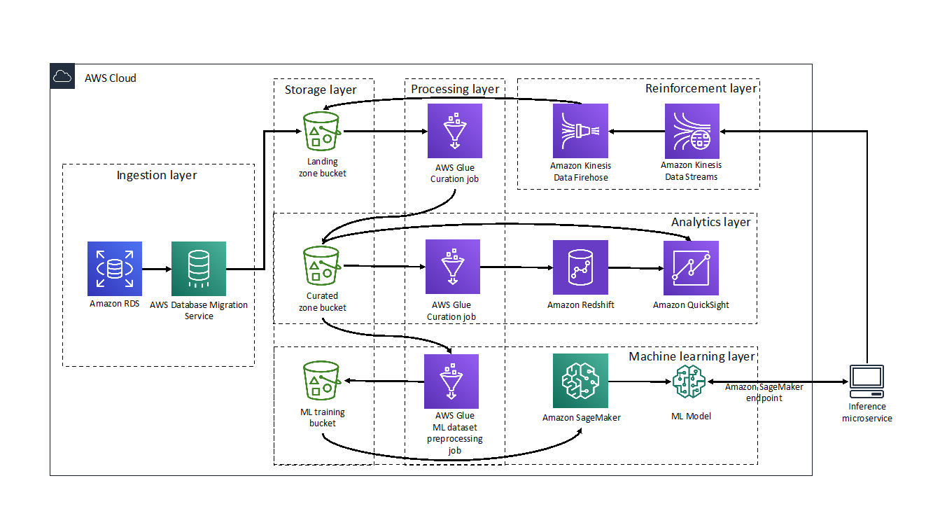
The ingestion layer is responsible for moving data from hospital production databases to the landing zone of the pipeline.
The hospital data was stored in an Amazon RDS for PostgreSQL instance and moved to the landing zone of the data lake using AWS Database Migration Service (DMS). DMS made migrating databases to the cloud simple and secure. Using its ongoing replication feature, MEDHOST and AWS implemented change data capture (CDC) quickly and efficiently so MEDHOST team could spend more time focusing on the most interesting parts of the pipeline.
The processing layer was responsible for performing extract, tranform, load (ETL) on the data to curate them for subsequent uses.
MEDHOST used AWS Glue within its data pipeline for crawling its data layers and performing ETL tasks. The hospital data copied from RDS to Amazon S3 was cleaned, curated, enriched, denormalized, and stored in parquet format to act as the heart of the MEDHOST data lake and a single source of truth to serve any further data needs. During the four-day Data Lab, MEDHOST and AWS targeted two needs: powering MEDHOST’s data warehouse used for analytics and feeding training data to the machine learning prediction model. Even though there were multiple challenges, data curation is a critical task which requires an SME. AWS Glue’s serverless nature, along with the SME’s support during the Data Lab, made developing the required transformations cost efficient and uncomplicated. Scaling and cluster management was addressed by the service, which allowed the developers to focus on cleaning data coming from homogenous hospital sources and translating the business logic to code.
The storage layer provided low-cost, secure, and efficient storage infrastructure.
MEDHOST used Amazon S3 as a core component of its data lake. AWS DMS migration tasks saved data to S3 in .CSV format. Crawling data with AWS Glue made this landing zone data queryable and available for further processing. The initial AWS Glue ETL job stored the parquet formatted data to the data lake and its curated zone bucket. MEDHOST also used S3 to store the .CSV formatted data set that will be used to train, test, and validate its machine learning prediction model.
The analytics layer gave MEDHOST pipeline reporting and dashboarding capabilities.
The data was in parquet format and partitioned in the curation zone bucket populated by the processing layer. This made querying with Amazon Athena or Amazon Redshift Spectrum fast and cost efficient.
From the Amazon Redshift cluster, MEDHOST created external tables that were used as staging tables for MEDHOST data warehouse and implemented an UPSERT logic to merge new data in its production tables. To showcase the reporting potential that was unlocked by the MEDHOST analytics layer, a connection was made to the Redshift cluster to Amazon QuickSight. Within minutes MEDHOST was able to create interactive analytics dashboards with filtering and drill-down capabilities such as a chart that showed the number of confirmed disease cases per US state.
The machine learning layer used MEDHOST’s existing data sets to train its cardiac risk prediction model and make it accessible via an endpoint.
Before getting into Data Lab, the MEDHOST team was not intimately familiar with machine learning. AWS Data Lab architects helped MEDHOST quickly understand concepts of machine learning and select a model appropriate for its use case. MEDHOST selected XGBoost as its model since cardiac prediction falls within regression technique. MEDHOST’s well architected data lake enabled it to quickly generate training, testing, and validation data sets using AWS Glue.
Amazon SageMaker abstracted underlying complexity of setting infrastructure for machine learning. With few clicks, MEDHOST started Jupyter notebook and coded the components leading to fitting and deploying its machine learning prediction model. Finally, MEDHOST created the endpoint for the model and ran REST calls to validate the endpoint and trained model. As a result, MEDHOST achieved the goal of predicting cardiac risk. Additionally, with Amazon QuickSight’s SageMaker integration, AWS made it easy to use SageMaker models directly in visualizations. QuickSight can call the model’s endpoint, send the input data to it, and put the inference results into the existing QuickSight data sets. This capability made it easy to display the results of the models directly in the dashboards. Read more about QuickSight’s SageMaker integration here.
Finally, the reinforcement layer guaranteed that the results of the MEDHOST model were captured and processed to improve performance of the model.
The MEDHOST team went beyond the original goal and created an inference microservice to interact with the endpoint for prediction, enabled abstracting of the machine learning endpoint with the well-defined domain REST endpoint, and added a standard security layer to the MEDHOST application.
When there is a real-time call from the facility, the inference microservice gets inference from the SageMaker endpoint. Records containing input and inference data are fed to the data pipeline again. MEDHOST used Amazon Kinesis Data Streams to push records in real time. However, since retraining the machine learning model does not need to happen in real time, the Amazon Kinesis Data Firehose enabled MEDHOST to micro-batch records and efficiently save them to the landing zone bucket so that the data could be reprocessed.
Collaborating with AWS Data Lab enabled MEDHOST to:
The MEDHOST team learned many concepts related to data analytics and machine learning within four days. AWS Data Lab truly helped MEDHOST deliver results in an accelerated manner.
 Pandian Velayutham is the Director of Engineering at MEDHOST. His team is responsible for delivering cloud solutions, integration and interoperability, and business analytics solutions. MEDHOST utilizes modern technology stack to provide innovative solutions to our customers. Pandian Velayutham is a technology evangelist and public cloud technology speaker.
 George Komninos is a Data Lab Solutions Architect at AWS. He helps customers convert their ideas to a production-ready data product. Before AWS, he spent 3 years at Alexa Information domain as a data engineer. Outside of work, George is a football fan and supports the greatest team in the world, Olympiacos Piraeus.
Post Syndicated from Bruce Schneier original https://www.schneier.com/blog/archives/2021/08/friday-squid-blogging-on-squid-brains.html
Interesting National Geographic article.
As usual, you can also use this squid post to talk about the security stories in the news that I haven’t covered.
Read my blog posting guidelines here.
Post Syndicated from Bruce Schneier original https://www.schneier.com/blog/archives/2021/08/more-on-apples-iphone-backdoor.html
In this post, I’ll collect links on Apple’s iPhone backdoor for scanning CSAM images. Previous links are here and here.
Apple says that hash collisions in its CSAM detection system were expected, and not a concern. I’m not convinced that this secondary system was originally part of the design, since it wasn’t discussed in the original specification.
Good op-ed from a group of Princeton researchers who developed a similar system:
Our system could be easily repurposed for surveillance and censorship. The design wasn’t restricted to a specific category of content; a service could simply swap in any content-matching database, and the person using that service would be none the wiser.
EDITED TO ADD (8/30): Good essays by Matthew Green and Alex Stamos, Ross Anderson, Edward Snowden, and Susan Landau. And also Kurt Opsahl.
Post Syndicated from Bruce Schneier original https://www.schneier.com/blog/archives/2021/08/t-mobile-data-breach.html
It’s a big one:
As first reported by Motherboard on Sunday, someone on the dark web claims to have obtained the data of 100 million from T-Mobile’s servers and is selling a portion of it on an underground forum for 6 bitcoin, about $280,000. The trove includes not only names, phone numbers, and physical addresses but also more sensitive data like social security numbers, driver’s license information, and IMEI numbers, unique identifiers tied to each mobile device. Motherboard confirmed that samples of the data “contained accurate information on T-Mobile customers.”
Post Syndicated from Bruce Schneier original https://www.schneier.com/blog/archives/2021/08/apples-neuralhash-algorithm-has-been-reverse-engineered.html
Apple’s NeuralHash algorithm — the one it’s using for client-side scanning on the iPhone — has been reverse-engineered.
Turns out it was already in iOS 14.3, and someone noticed:
Early tests show that it can tolerate image resizing and compression, but not cropping or rotations.
We also have the first collision: two images that hash to the same value.
The next step is to generate innocuous images that NeuralHash classifies as prohibited content.
This was a bad idea from the start, and Apple never seemed to consider the adversarial context of the system as a whole, and not just the cryptography.
Post Syndicated from Bruce Schneier original https://www.schneier.com/blog/archives/2021/08/tetris-chinese-espionage-tool.html
I’m starting to see writings about a Chinese espionage tool that exploits website vulnerabilities to try and identify Chinese dissidents.
Post Syndicated from Eric Johnson original https://aws.amazon.com/blogs/compute/configuring-cors-on-amazon-api-gateway-apis/
Configuring cross-origin resource sharing (CORS) settings for a backend server is a typical challenge that developers face when building web applications. CORS is a layer of security enforced by modern browsers and is required when the client domain does not match the server domain. The complexity of CORS often leads developers to abandon it entirely by allowing all-access with the proverbial “*” permissions setting. However, CORS is an essential part of your application’s security posture and should be correctly configured.
This post explains how to configure CORS on Amazon API Gateway resources to enforce the least privileged access to an endpoint using the AWS Serverless Application Model (AWS SAM). I cover the notable CORS differences between REST APIs and HTTP APIs. Finally, I introduce you to the Amazon API Gateway CORS Configurator. This is a tool built by the AWS Serverless Developer Advocacy team to help you configure CORS settings properly.
CORS is a mechanism by which a server limits access through the use of headers. In requests that are not considered simple, the server relies on the browser to make a CORS preflight or OPTIONS request. A full request looks like this:
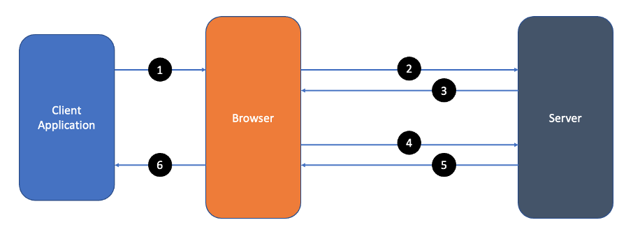
CORS request flow
The preflight request verifies the requirements of the server by indicating the origin, method, and headers to come in the actual request.
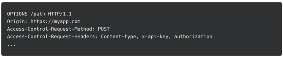
OPTIONS preflight request
The response from the server differs based on the backend you are using. Some servers respond with the allowed origin, methods, and headers for the endpoint.
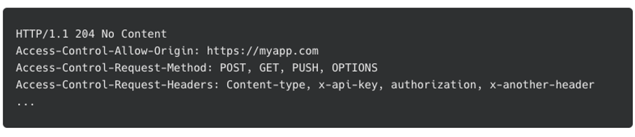
OPTIONS preflight response
Others only return CORS headers if the requested origin, method, and headers meet the requirements of the server. If the requirements are not met, then the response does not contain any CORS access control headers. The browser verifies the request’s origin, method, and headers against the data returned in the preflight response. If validation fails, the browser throws a CORS error and halts the request. If the validation is successful, the browser continues with the actual request.
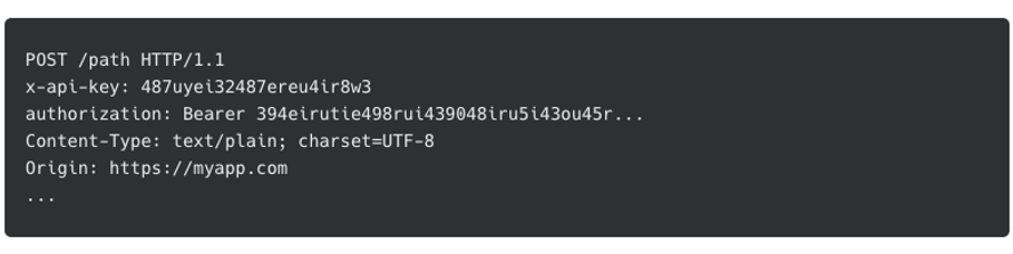
Actual request
The browser only sends the access-control-allow-origin header to verify the requesting origin during the actual request. The server then responds with the requested data.

Actual response
This step is where many developers run into issues. Notice the endpoint of the actual request returns the access-control-allow-origin header. The browser once again verifies this before taking action.
Both the preflight and the actual response require CORS configuration, and it looks different depending on whether you select REST API or HTTP API.
While Amazon API Gateway offers several API endpoint types, this post focuses on REST API (v1) and HTTP API (v2). Both types create a representational state transfer (REST) endpoint that proxies an AWS Lambda function and other AWS services or third-party endpoints. Both types process preflight requests. However, there are differences in both the configuration, and the format of the integration response.
Before walking through the configuration examples, it is important to understand some terminology:
A popular use of API Gateway REST APIs is to proxy one or more Lambda functions to build a serverless backend. In this pattern, API Gateway does not modify the request or response payload. Therefore, REST API manages CORS through a combination of preflight configuration and a properly formed response from the Lambda function.
Configuring CORS on REST APIs is generally configured in four lines of code with AWS SAM:
Cors:
  AllowMethods: "'GET, POST, OPTIONS'"
  AllowOrigin: "'http://localhost:3000'"
  AllowHeaders: "'Content-type, x-api-key'"
This code snippet creates a MOCK API resource that processes all preflight requests for that resource. This configuration is an example of the least privileged access to the server. It only allows GET, POST, and OPTIONS methods from a localhost endpoint on port 3000. Additionally, it only allows the Content-type and x-api-key CORS headers.
Notice that the preflight response only allows one origin to call this API. To enable multiple origins with REST APIs, use ‘*’ for the allow-control-allow-origin header. Alternatively, use a Lambda function integration instead of a MOCK integration to set the header dynamically based on the origin of the caller.
When configuring CORS for REST APIs that require authentication, it is important to configure the preflight endpoint without authorization required. The preflight is generated by the browser and does not include the credentials by default. To remove the authorizer from the OPTIONS method add the AddDefaultAuthorizerToCorsPreflight: false setting to the authorization configuration.
Auth:
  AddDefaultAuthorizerToCorsPreflight: false
  Authorizers:
    MyCognitoAuth:

…In REST APIs proxy configurations, CORS settings only apply to the OPTIONS endpoint and cover only the preflight check by the browser. The Lambda function backing the method must respond with the appropriate CORS information to handle CORS properly in the actual response. The following is an example of a proper response:
{
  "statusCode": 200,
  "headers": {
    "access-control-allow-origin":" http://localhost:3000",
  }
  "body": {"message": "hello world"}
}
In this response, the critical parts are the statusCode returned to the user as the response status and the access-control-allow-origin header required by the browser’s CORS validation.
Like REST APIs, Amazon API Gateway HTTP APIs are commonly used to proxy Lambda functions and are configured to handle preflight requests. However, unlike REST APIs, HTTP APIs handle CORS for the actual API response as well.
The following example shows how to configure CORS on HTTP APIs with AWS SAM:
CorsConfiguration
  AllowMethods:
    - GET
    - POST
    - OPTIONS
  AllowOrigin:
    - http://localhost:3000
    - https://myproddomain.com
  AllowHeaders:
    - Content-type
    - x-api-key
This template configures HTTP APIs to manage CORS for the preflight requests and the actual requests. Note that the AllowOrigin section allows more than one domain. When the browser makes a request, HTTP APIs checks the list for the incoming origin. If it exists, HTTP APIs adds it to the access-control-allow-origin header in the response.
When configuring CORS for HTTP APIs with authorization configured, HTTP APIs automatically configures the preflight endpoint without authorization required. The only caveat to this is the use of the $default route. When configuring a $default route, all methods and resources are handled by the default route and the integration behind it. This includes the preflight OPTIONS method.
There are two options to handle preflight. First, and recommended, is to break out the routes individually. Create a route specifically for each method and resource as needed. The second is to create an OPTIONS /{proxy+} method to override the $defaut route for preflight requests.
Unlike REST APIs, by default, HTTP APIs modify the response for the actual request by adding the appropriate CORS headers based upon the CORS configuration. The following is an example of a simple response:
"hello world"HTTP APIs then constructs the complete response with your data, status code, and any required CORS headers:
{
  "statusCode": 200,
  "headers": {
    "access-control-allow-origin":"[appropriate origin]",
  }
  "body": "hello world"
}
To set the status code manually, configure your response as follows:
{
  "statusCode": 201,
  "body": "hello world"
}
To manage the complete response like in REST APIs, set the payload format to version one. The payload format for HTTP API changes the structure of the payload sent to the Lambda function and the expected response from the Lambda function. By default, HTTP API uses version two, which includes the dynamic CORS settings. For more information, read how the payload version affects the response format in the documentation.
The AWS serverless developer advocacy team built the Amazon API Gateway CORS Configurator to help you configure CORS for your serverless applications.

Amazon API Gateway CORS Configurator
Start by entering the information on the left. The CORS Configurator builds the proper snippets to add the CORS settings to your AWS SAM template as you add more information. The utility demonstrates adding the configuration to all APIs in the template by using the Globals section. You can also add to an API’s specific resource to affect only that API.
Additionally, the CORS Configurator constructs an example response based on the API type you are using.
This utility is currently in preview, and we welcome your feedback on how we can improve it. Feel free to open an issue on GitHub at https://github.com/aws-samples/amazon-api-gateway-cors-configurator.
CORS can be challenging. For API Gateway, CORS configuration is the number one question developers ask. In this post, I give an overview of CORS with a link to an in-depth explanation. I then show how to configure API Gateway to create the least privileged access to your server using CORS. I also discuss the differences in how REST APIs and HTTP APIs handle CORS. Finally, I introduced you to the API Gateway CORS Configurator to help you configure CORS using AWS SAM.
I hope to provide you with enough information that you can avoid opening up your servers with the “*” setting for CORS. Take the time to understand your application and limit requests to only methods you support and from only originating hosts you intended.
For more serverless content, go to Serverless Land.
Post Syndicated from Schneier.com Webmaster original https://www.schneier.com/blog/archives/2021/08/upcoming-speaking-engagements-11.html
This is a current list of where and when I am scheduled to speak:
The list is maintained on this page.
Post Syndicated from Bruce Schneier original https://www.schneier.com/blog/archives/2021/08/friday-squid-blogging-a-good-year-for-squid.html
Improved ocean conditions are leading to optimism about this year’s squid catch.
As usual, you can also use this squid post to talk about the security stories in the news that I haven’t covered.
Read my blog posting guidelines here.
Post Syndicated from Bruce Schneier original https://www.schneier.com/blog/archives/2021/08/using-ai-to-scale-spear-phishing.html
The problem with spear phishing is that it takes time and creativity to create individualized enticing phishing emails. Researchers are using GPT-3 to attempt to solve that problem:
The researchers used OpenAI’s GPT-3 platform in conjunction with other AI-as-a-service products focused on personality analysis to generate phishing emails tailored to their colleagues’ backgrounds and traits. Machine learning focused on personality analysis aims to be predict a person’s proclivities and mentality based on behavioral inputs. By running the outputs through multiple services, the researchers were able to develop a pipeline that groomed and refined the emails before sending them out. They say that the results sounded “weirdly human” and that the platforms automatically supplied surprising specifics, like mentioning a Singaporean law when instructed to generate content for people living in Singapore.
While they were impressed by the quality of the synthetic messages and how many clicks they garnered from colleagues versus the human-composed ones, the researchers note that the experiment was just a first step. The sample size was relatively small and the target pool was fairly homogenous in terms of employment and geographic region. Plus, both the human-generated messages and those generated by the AI-as-a-service pipeline were created by office insiders rather than outside attackers trying to strike the right tone from afar.
It’s just a matter of time before this is really effective. Combine it with voice and video synthesis, and you have some pretty scary scenarios. The real risk isn’t that AI-generated phishing emails are as good as human-generated ones, it’s that they can be generated at much greater scale.
Defcon presentation and slides. Another news article
Post Syndicated from Richard H Boyd original https://aws.amazon.com/blogs/devops/introducing-public-builds-for-aws-codebuild/
Using AWS CodeBuild, you can now share both the logs and the artifacts produced by CodeBuild projects. This blog post explains how to configure an existing CodeBuild project to enable public builds.
AWS CodeBuild is a fully managed continuous integration service that compiles source code, runs tests, and produces software packages that are ready to deploy. With CodeBuild, you don’t need to provision, manage, and scale your own build servers. With this new feature, you can now make the results of a CodeBuild project build publicly viewable. Public builds simplify the collaboration workflow for open source projects by allowing contributors to see the results of Continuous Integration (CI) tasks.
During a project build, CodeBuild will place build logs in either Amazon Simple Storage Service (Amazon S3) or Amazon CloudWatch, depending on how the customer has configured the project’s LogsConfig property. Optionally, a project build can produce artifacts that persist after the build has completed. During a project build that has public builds enabled, CodeBuild will set an environment variable named CODEBUILD_PUBLIC_BUILD_URL that supplies the URL for that build’s publicly viewable logs and artifacts. When a user navigates to that URL, CodeBuild will use an AWS Identity and Access Management (AWS IAM) Role (defined by the project maintainer) to fetch build logs and available artifacts and displays these.
To enable public builds for a project:
example-public-builds-role. This creates a new IAM role with the permissions defined in the next section of this blog post.Project builds will now have the build logs and artifacts made available at the URL listed in the Public project URL section of the Configuration panel within the project’s resource page.

Now the CI build statuses within pull requests for the GitHub repository will include a public link to the build results. When a pull request is created in the repository, CodeBuild will start a project build and provide commit status updates during the build with a link to the public build information. This link is available as a hyperlink from the Details section of the commit status message.

This new feature introduces a new IAM role for CodeBuild. The new role is assumed by the CodeBuild service and needs read access to the build logs and any potential artifacts you would like to make publicly available. In the previous example, we had configured the CodeBuild project to store logs in Amazon CloudWatch and placed our build artifacts in Amazon S3 (namespaced to the build ID). The following AWS CloudFormation template will create an IAM Role with the appropriate least-privilege policies for accessing the public build results.
Parameters:
  LogGroupName:
    Type: String
    Description: prefix for the CloudWatch log group name
  ArtifactBucketArn:
    Type: String
    Description: Arn for the Amazon S3 bucket used to store build artifacts.

Resources:
  PublicReadRole:
    Type: AWS::IAM::Role
    Properties:
      AssumeRolePolicyDocument:
        Statement:
        - Action: ['sts:AssumeRole']
          Effect: Allow
          Principal:
            Service: [codebuild.amazonaws.com]
        Version: '2012-10-17'
      Path: /

  PublicReadPolicy:
    Type: 'AWS::IAM::Policy'
    Properties:
      PolicyName: PublicBuildPolicy
      PolicyDocument:
        Version: "2012-10-17"
        Statement:
          - Effect: Allow
            Action:
              - "logs:GetLogEvents"
            Resource:
              - !Sub "arn:aws:logs:${AWS::Region}:${AWS::AccountId}:log-group:${LogGroupName}:*"
          - Effect: Allow
            Action:
              - "s3:GetObject"
              - "s3:GetObjectVersion"
            Resource:
              - !Sub "${ArtifactBucketArn}/*"
      Roles:
- !Ref PublicReadRoleUsing AWS CloudFormation, you can provision CodeBuild projects using infrastructure as code (IaC). To update an existing CodeBuild project to enable public builds add the following two fields to your project definition:
  CodeBuildProject:
    Type: AWS::CodeBuild::Project
    Properties:
      ServiceRole: !GetAtt CodeBuildRole.Arn
      LogsConfig:
        CloudWatchLogs:
          GroupName: !Ref LogGroupName
          Status: ENABLED
          StreamName: ServerlessRust
      Artifacts:
        Type: S3
        Location: !Ref ArtifactBucket
        Name: ServerlessRust
        NamespaceType: BUILD_ID
        Packaging: ZIP
      Environment:
        Type: LINUX_CONTAINER
        ComputeType: BUILD_GENERAL1_LARGE
        Image: aws/codebuild/standard:4.0
        PrivilegedMode: true
      Triggers:
        BuildType: BUILD
        Webhook: true
        FilterGroups:
          - - Type: EVENT
              Pattern: PULL_REQUEST_CREATED,PULL_REQUEST_UPDATED
      Source:
        Type: GITHUB
        Location: "https://github.com/richardhboyd/ServerlessRust.git"
        BuildSpec: |
          version: 0.2
          phases:
            build:
              commands:
                - sam build
          artifacts:
            files:
              - .aws-sam/build/**/*
            discard-paths: no
      Visibility: PUBLIC_READ
ResourceAccessRole: !Ref PublicReadRole # Note that this references the role defined in the previous section. If a project has public builds enabled and you would like to disable it, you can clear the check-box named Enable public build access in the project configuration or set the Visibility to PRIVATE in the CloudFormation definition for the project. To prevent any project in your AWS account from using public builds, you can set an AWS Organizations service control policy (SCP) to deny the IAM Action CodeBuild:UpdateProjectVisibility
With CodeBuild public builds, you can now share build information for your open source projects with all contributors without having to grant them direct access to your AWS account. This post explains how to enable public builds with AWS CodeBuild using both the console and CloudFormation, create a least-privilege IAM role for sharing the public build results, and how to disable public builds for a project.
Post Syndicated from Bruce Schneier original https://www.schneier.com/blog/archives/2021/08/cobolt-strike-vulnerability-affects-botnet-servers.html
Cobalt Strike is a security tool, used by penetration testers to simulate network attackers. But it’s also used by attackers — from criminals to governments — to automate their own attacks. Researchers have found a vulnerability in the product.
The main components of the security tool are the Cobalt Strike client — also known as a Beacon — and the Cobalt Strike team server, which sends commands to infected computers and receives the data they exfiltrate. An attacker starts by spinning up a machine running Team Server that has been configured to use specific “malleability” customizations, such as how often the client is to report to the server or specific data to periodically send.
Then the attacker installs the client on a targeted machine after exploiting a vulnerability, tricking the user or gaining access by other means. From then on, the client will use those customizations to maintain persistent contact with the machine running the Team Server.
The link connecting the client to the server is called the web server thread, which handles communication between the two machines. Chief among the communications are “tasks” servers send to instruct clients to run a command, get a process list, or do other things. The client then responds with a “reply.”
Researchers at security firm SentinelOne recently found a critical bug in the Team Server that makes it easy to knock the server offline. The bug works by sending a server fake replies that “squeeze every bit of available memory from the C2’s web server thread….”
It’s a pretty serious vulnerability, and there’s already a patch available. But — and this is the interesting part — that patch is available to licensed users, which attackers often aren’t. It’ll be a while before that patch filters down to the pirated copies of the software, and that time window gives defenders an opportunity. They can simulate a Cobolt Strike client, and leverage this vulnerability to reply to servers with messages that cause the server to crash.
Post Syndicated from Bruce Schneier original https://www.schneier.com/blog/archives/2021/08/apple-adds-a-backdoor-to-imesssage-and-icloud-storage.html
Apple’s announcement that it’s going to start scanning photos for child abuse material is a big deal. (Here are five news stories.) I have been following the details, and discussing it in several different email lists. I don’t have time right now to delve into the details, but wanted to post something.
EFF writes:
There are two main features that the company is planning to install in every Apple device. One is a scanning feature that will scan all photos as they get uploaded into iCloud Photos to see if they match a photo in the database of known child sexual abuse material (CSAM) maintained by the National Center for Missing & Exploited Children (NCMEC). The other feature scans all iMessage images sent or received by child accounts — that is, accounts designated as owned by a minor — for sexually explicit material, and if the child is young enough, notifies the parent when these images are sent or received. This feature can be turned on or off by parents.
This is pretty shocking coming from Apple, which is generally really good about privacy. It opens the door for all sorts of other surveillance, since now that the system is built it can be used for all sorts of other messages. And it breaks end-to-end encryption, despite Apple’s denials:
Does this break end-to-end encryption in Messages?
No. This doesn’t change the privacy assurances of Messages, and Apple never gains access to communications as a result of this feature. Any user of Messages, including those with with communication safety enabled, retains control over what is sent and to whom. If the feature is enabled for the child account, the device will evaluate images in Messages and present an intervention if the image is determined to be sexually explicit. For accounts of children age 12 and under, parents can set up parental notifications which will be sent if the child confirms and sends or views an image that has been determined to be sexually explicit. None of the communications, image evaluation, interventions, or notifications are available to Apple.
Notice Apple changing the definition of “end-to-end encryption.” No longer is the message a private communication between sender and receiver. A third party is alerted if the message meets a certain criteria.
This is a security disaster. Read tweets by Matthew Green and Edward Snowden. Also this. I’ll post more when I see it.
Beware the Four Horsemen of the Information Apocalypse. They’ll scare you into accepting all sorts of insecure systems.
EDITED TO ADD: This is a really good write-up of the problems.
EDITED TO ADD: Alex Stamos comments.
An open letter to Apple criticizing the project.
A leaked Apple memo responding to the criticisms. (What are the odds that Apple did not intend this to leak?)
EDITED TO ADD: John Gruber’s excellent analysis.
EDITED TO ADD (8/11): Paul Rosenzweig wrote an excellent policy discussion.
EDITED TO ADD (8/13): Really good essay by EFF’s Kurt Opsahl. Ross Anderson did an interview with Glenn Beck. And this news article talks about dissent within Apple about this feature.
The Economist has a good take. Apple responds to criticisms. (It’s worth watching the Wall Street Journal video interview as well.)
EDITED TO ADD (8/14): Apple released a threat model