Post Syndicated from Sheila Busser original https://aws.amazon.com/blogs/compute/configuring-low-latency-connectivity-between-aws-outposts-rack-using-coip-and-on-premises-data/
This blog post is written by, Leonardo Azize Martins, Cloud Infrastructure Architect, Professional Services.
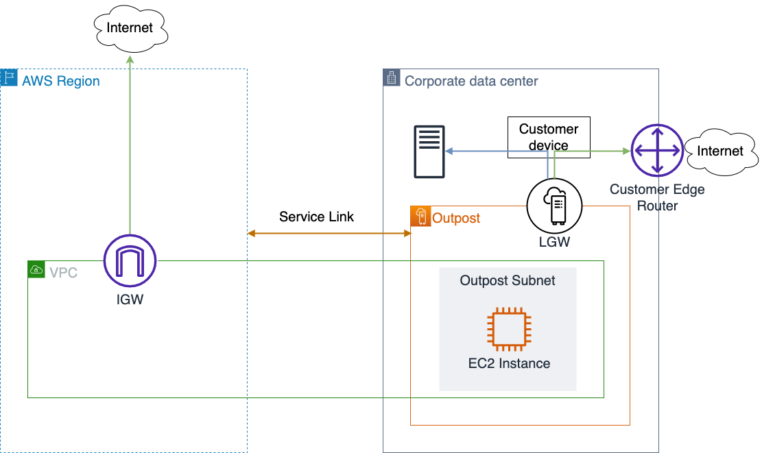
AWS Outposts rack enables applications that need to run on-premises due to low latency, local data processing, or local data storage needs by connecting Outposts rack to your on-premises network via the local gateway (LGW).
Each Outpost rack includes a local gateway to provide low latency connectivity between the Outpost and any local data sources, end users, local machinery and equipment, or local databases. If you have an Outpost rack, you can include a local gateway as the target in your VPC subnet route table where the destination is your on-premises network. Local gateways are only available for Outposts rack and can only be used in route tables where the VPC has been associated with an LGW.
In a previous blog post on connecting AWS Outposts to on-premises data sources, you learned the different use cases to use AWS Outposts connected with your local network. In this post, you will dive deep into local gateway usage and specific details about it. You will learn how to use Outpost local gateway when it is configured as Customer-owned IP addresses (CoIP) mode. You will also learn how to integrate it with your Amazon Virtual Private Cloud (Amazon VPC) and how different routes work regarding Amazon Elastic Compute Cloud (Amazon EC2) instances running on Outposts.
Overview of solution
The primary role of a local gateway is to provide connectivity from an Outpost to your local on-premises LAN. It also provides AWS Outposts connectivity to the internet through your on-premises network via the LGW, so you don’t need to rely on an internet gateway (IGW). The local gateway can also provide a data plane path back to the AWS Region. If you already have connectivity between your LAN and the Region through AWS Site-to-Site VPN or AWS Direct Connect, you can use the same path to connect from the Outpost to the AWS Region privately.
Outpost subnet
Public subnets and private subnets are important concepts to understand for Outposts networking. A public subnet has a route to an internet gateway. The same concept applies to Outpost subnets, when a public subnet exists on Outposts, it will have a route to an internet gateway, which will use a service link as a communication path between an Outpost and the internet gateway in the parent AWS Region.

A private subnet does not have a direct route to the internet gateway. It will only be local inside the VPC, or it could have a route to a Network Address Translation (NAT) gateway. In both cases, the communication between Outpost subnets and AWS Region subnets will be done via the service link.

Your subnet can be private and only be allowed to communicate with your on-premises network. You just need a route pointing to the LGW.

You can also provide internet connectivity to your Outpost subnets via LGW. In this case, it will not use the service link. As soon as it traverses the LGW and goes to your next hop, it will follow your routing flow to the internet.

Routing
By default, every Outpost subnet inherits the main route table from its VPC. You can create a custom route table and associate it with an Outpost subnet. You can include a local gateway as the target when the destination is your on-premises network. A local gateway can only be used in VPC and subnet route tables that are exclusively associated with an Outpost subnet. If the route table is associated with an Outpost subnet and a Region subnet, it will not allow you to add a local gateway as the target.
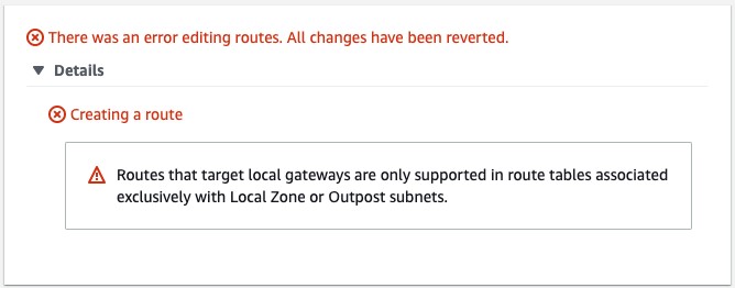
Local gateways are also not supported in the main route table.

The local gateway advertises Outpost IP address ranges to your on-premises network via BGP. In the other direction, from an on-premises network to the Outpost, it doesn’t use BGP, which means there is no propagation. You need to configure your VPC route table with static routes.
As of this writing, the LGW does not support jumbo frame.
Outposts IP addresses
Outposts can be configured in customer-owned IP (CoIP) mode.
Customer-owned IP
During the installation process, uses information that you provide about your on-premises network to create an address pool, which is known as a customer-owned IP address pool (CoIP pool). AWS then assigns it to the local gateway for use and advertises back to your on-premises network through BGP.
CoIP addresses provide local or external connectivity to resources in your Outpost subnets through your on-premises network. You can assign these IP addresses to resources on your Outpost, such as an EC2 instance, by allocating a new Elastic IP address from the customer-owned IP pool and then assigning this new Elastic IP address to your EC2 instance.
A local gateway serves as NAT for EC2 instances that have been assigned addresses from your customer-owned IP pool.
You can optionally share your customer-owned pool with multiple AWS accounts in your AWS Organizations using the AWS Resource Access Manager (RAM). After you share the pool, participants can allocate and associate Elastic IP addresses from the customer-owned IP pool.
Communication between your Outpost and on-premises network will use the CoIP Elastic IP addresses to address instances in the Outpost; the VPC CIDR range is not used.
Walkthrough
You will follow the steps required to configure your VPC to use LGW configured as CoIP, including:
- Associate your VPC with the LGW route table.
- Create an Outposts subnet.
- Create and associate the VPC route table with the subnet.
- Add a route to on-premises network with LGW as the target.
Prerequisites
For this walkthrough, you should have the following prerequisites:
- An AWS account.
- An Outpost that consists of one or more Outposts racks configured in CoIP mode.
Associate VPC with LGW route table
Use the following procedure to associate a VPC with the LGW route table. You can’t associate VPCs that have a CIDR block conflict.
- Open the AWS Outposts console.
- In the navigation pane, choose Local gateway route tables.
- Select the route table and then choose Actions, Associate VPC.
- For VPC ID, select the VPC to associate with the local gateway route table.
- Choose Associate VPC.
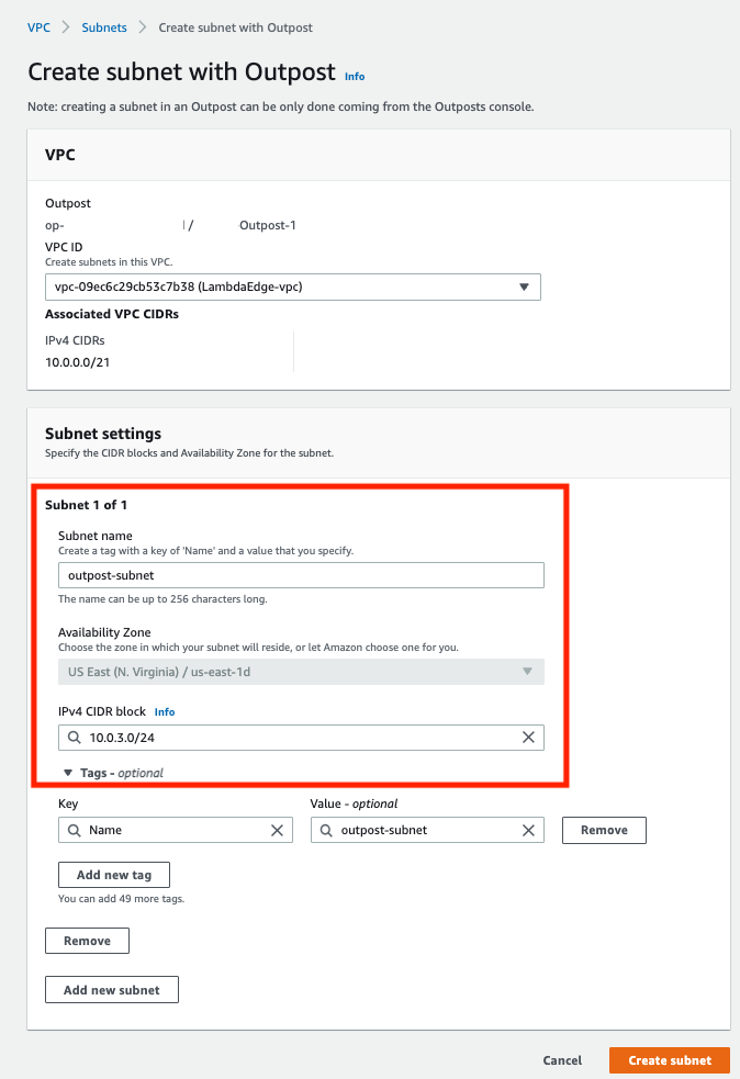
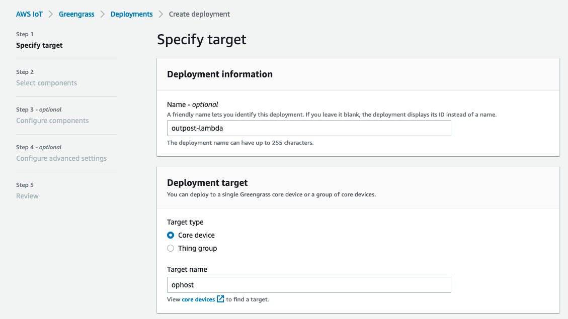
Create an Outpost subnet
You can add Outpost subnets to any VPC in the parent AWS Region for the Outpost. When you do so, the VPC also spans the Outpost.
- Open the AWS Outposts console.
- On the navigation pane, choose Outposts.
- Select the Outpost, and then choose Actions, Create subnet.
- Select the VPC and specify an IP address range for the subnet.
- Choose Create.
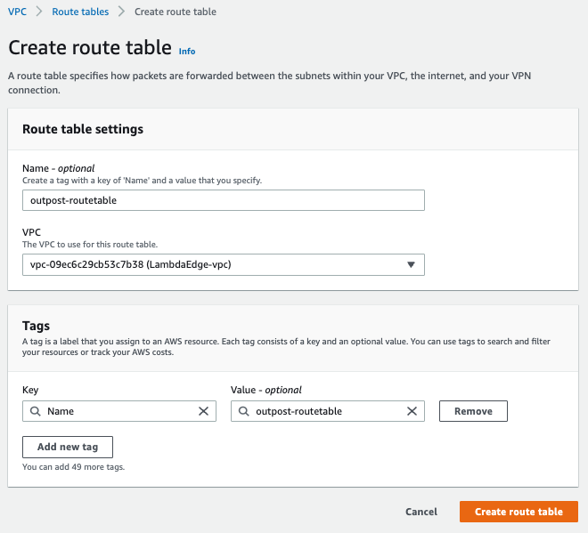
Create and associate VPC route table with the Outpost subnet
You can create a custom route table for your VPC using the Amazon VPC console. It is a best practice to have one specific route table for each subnet.
- Open the Amazon VPC console.
- In the navigation pane, choose Route Tables.
- Choose Create route table.
- For VPC, choose your VPC.
- Choose Create.
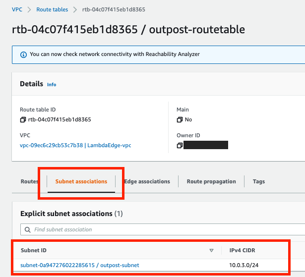
- On the Subnet associations tab, choose Edit subnet associations.
- Select the check box for the subnet to associate with the route table and then choose Save associations.
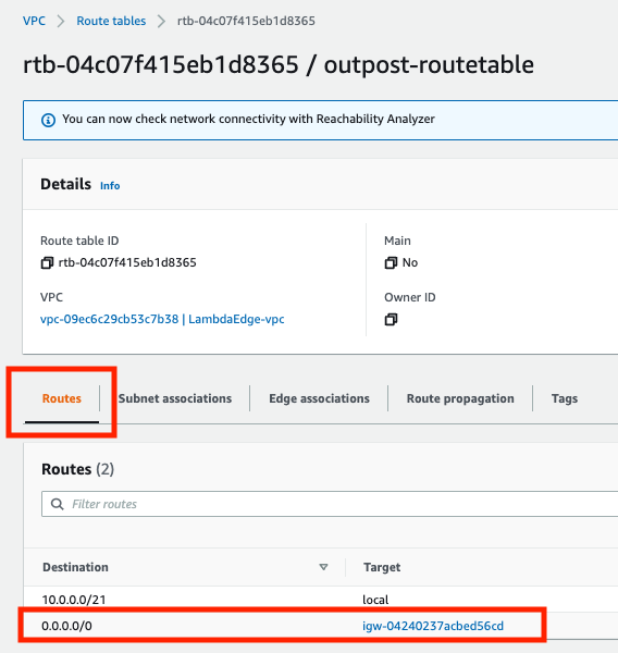
Add a route to on-premises network with LGW as the target
You can add a route to a route table using the Amazon VPC console.
- Open the Amazon VPC console.
- In the navigation pane, choose Route Tables and select
- Choose Actions, Edit routes.
- Choose Add route. For Destination, enter the destination CIDR block, a single IP address, or the ID of a prefix list.
- Choose Save routes.
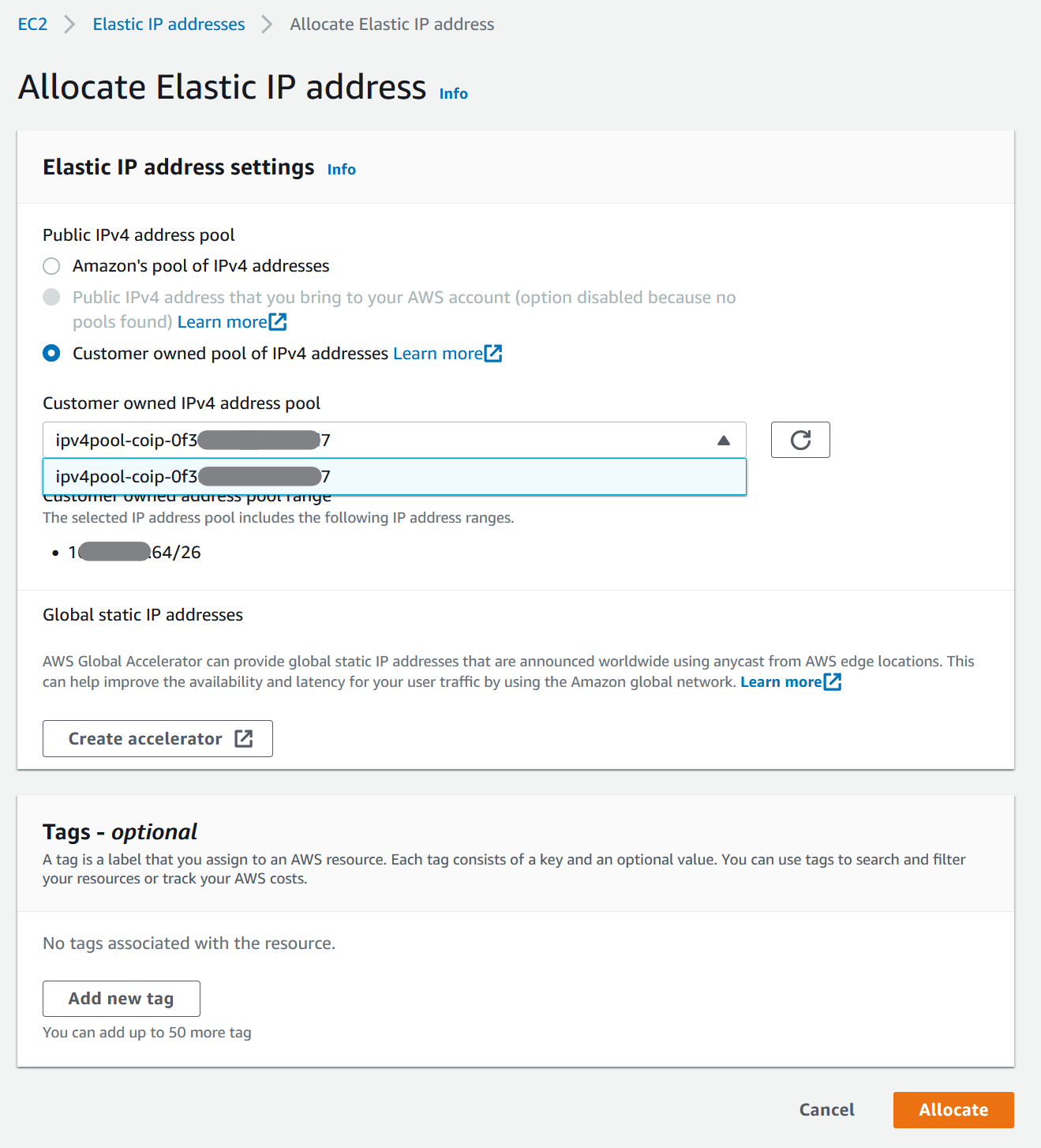
Allocate and associate a customer-owned IP address
- Open the Amazon EC2 console.
- In the navigation pane, choose Elastic IPs.
- Choose Allocate new address.
- For Network Border Group, select the location from which the IP address is advertised.
- For Public IPv4 address pool, choose Customer owned IPv4 address pool.
- For Customer owned IPv4 address pool, select the pool that you configured.
- Choose Allocate and close the confirmation screen.
- In the navigation pane, choose Elastic IPs.
- Select an Elastic IP address and choose Actions, Associate address.
- Select the instance from Instance and then choose Associate.
For more information about Launch an instance on your Outpost, refer to the AWS Outposts User Guide.
Cleaning up
To avoid incurring future charges, delete the resources, like EC2 instances.
Conclusion
In this post, I covered how to use the Outposts rack local gateway to communicate with your on-premises network. You learned how a subnet route table can influence the connectivity of public or private Outpost instances.
To learn more, check out our Outposts local gateway documentation and the networking reference architecture.