Post Syndicated from Geographics original https://www.youtube.com/watch?v=S6TjtkTl3iA
The future of NGINX
Post Syndicated from original https://lwn.net/Articles/905855/
This
blog post on the NGINX corporate site describes the plans for this web
server project in the coming year.
For the core NGINX Open Source software, we continue to add new
features and functionality and to support more operating system
platforms. Two critical capabilities for security and scalability
of web applications and traffic, HTTP3 and QUIC, are coming in the
next version we ship.
Let’s Architect! Architecting for the edge
Post Syndicated from Luca Mezzalira original https://aws.amazon.com/blogs/architecture/lets-architect-architecting-for-the-edge/
Edge computing comprises elements of geography and networking and brings computing closer to the end users of the application.
For example, using a content delivery network (CDN) such as AWS CloudFront can help video streaming providers reduce latency for distributing their material by taking advantage of caching at the edge. Another example might look like an Internet of Things (IoT) solution that helps a company run business logic in remote areas or with low latency.
IoT is a challenging field because there are multiple aspects to consider as architects, like hardware, protocols, networking, and software. All of these aspects must be designed to interact together and be fault tolerant.
In this edition of Let’s Architect!, we share resources that are helpful for teams that are approaching or expanding their workloads for edge computing We cover macro topics such as security, best practices for IoT, patterns for machine learning (ML), and scenarios with strict latency requirements.
Build Machine Learning at the edge applications
In Let’s Architect! Architecting for Machine Learning, we touched on some of the most relevant aspects to consider while putting ML into production. However, in many scenarios, you may also have specific constraints like latency or a lack of connectivity that require you to design a deployment at the edge.
This blog post considers a solution based on ML applied to agriculture, where a reliable connection to the Internet is not always available. You can learn from this scenario, which includes information from model training to deployment, to design your ML workflows for the edge. The solution uses Amazon SageMaker in the cloud to explore, train, package, and deploy the model to AWS IoT Greengrass, which is used for inference at the edge.
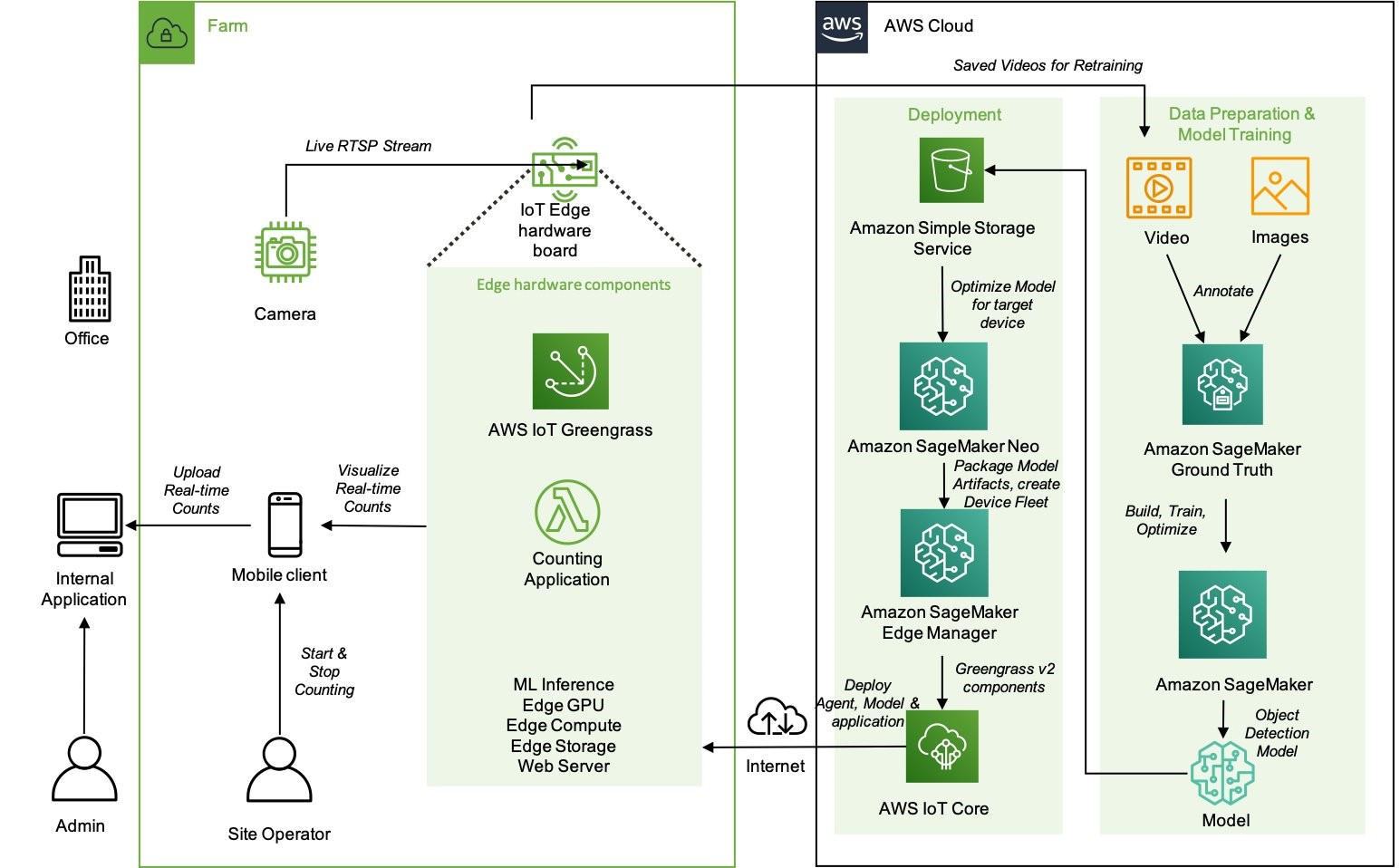
High-level architecture of the components that reside on the farm and how they interact with the cloud environment
Security at the edge
Security is one of the fundamental pillars described in the AWS Well-Architected Framework. In all organizations, security is a major concern both for the business and the technical stakeholders. It impacts the products they are building and the perception that customers have.
We covered security in Let’s Architect! Architecting for Security, but we didn’t focus specifically on edge technologies. This whitepaper shows approaches for implementing a security strategy at the edge, with a focus on describing how AWS services can be used. You can learn how to secure workloads designed for content delivery, as well as how to implement network protection to defend against DDoS attacks and protect your IoT solutions.

The AWS Well-Architected Tool is designed to help you review the state of your applications and workloads. It provides a central place for architectural best practices and guidance
AWS Outposts High Availability Design and Architecture Considerations
AWS Outposts allows companies to run some AWS services on-premises, which may be crucial to comply with strict data residency or low latency requirements. With Outposts, you can deploy servers and racks from AWS directly into your data center.
This whitepaper introduces architectural patterns, anti-patterns, and recommended practices for building highly available systems based on Outposts. You will learn how to manage your Outposts capacity and use networking and data center facility services to set up highly available solutions. Moreover, you can learn from mental models that AWS engineers adopted to consider the different failure modes and the corresponding mitigations, and apply the same models to your architectural challenges.

An Outpost deployed in a customer data center and connected back to its anchor Availability Zone and parent Region
AWS IoT Lens
The AWS Well-Architected Lenses are designed for specific industry or technology scenarios. When approaching the IoT domain, the AWS IoT Lens is a key resource to learn the best practices to adopt for IoT. This whitepaper breaks down the IoT workloads into the different subdomains (for example, communication, ingestion) and maps the AWS services for IoT with each specific challenge in the corresponding subdomain.
As architects and developers, we tend to automate and reduce the risk of human errors, so the IoT Lens Checklist is a great resource to review your workloads by following a structured approach.

Workload context checklist from the IoT Lens Checklist
See you next time!
Thanks for joining our discussion on architecting for the edge! See you in two weeks when we talk about database architectures on AWS.
Other posts in this series
- Let’s Architect! Architecting for Sustainability
- Let’s Architect! Architecting for Machine Learning
- Let’s Architect! Architecting for Security
- Let’s Architect! Tools for Cloud Architects
- Let’s Architect! Architecting for Blockchain
- Let’s Architect! Architecting microservices with containers
- Let’s Architect! Using open-source technologies on AWS
- Let’s Architect! Serverless architecture on AWS
- Let’s Architect! Creating resilient architecture
- Let’s Architect! Architecting for governance and management
- Let’s Architect! Architecting for front end
- Let’s Architect! Understanding the build versus buy dilemma
- Let’s Architect! Architecting for DevOps
- Let’s Architect! Designing Well-Architected systems
- Let’s Architect! Architecting for big data workloads
Looking for more architecture content?
AWS Architecture Center provides reference architecture diagrams, vetted architecture solutions, Well-Architected best practices, patterns, icons, and more!
Security updates for Wednesday
Post Syndicated from original https://lwn.net/Articles/905853/
Security updates have been issued by Fedora (vim), SUSE (cosign, dpdk, freeciv, gfbgraph, kernel, nim, p11-kit, perl-HTTP-Daemon, python-lxml, and python-treq), and Ubuntu (linux-oem-5.14, open-vm-tools, and twisted).
A peer instruction approach for engaging girls in the Computing classroom: Study results
Post Syndicated from Katharine Childs original https://www.raspberrypi.org/blog/gender-balance-in-computing-peer-instruction-approach-engaging-girls/
Today, we are publishing the third report of our findings from our Gender Balance in Computing research programme. This report shares the outcomes from the Peer Instruction project, which is the last in our set of three interventions that has explored teaching approaches to engage more girls in computing.

The premise of the teaching approach research is that the way Computing is taught may not always match the teaching approaches to which girls are most likely to respond positively [1]. As with the Storytelling project and the Pair Programming project, this project aimed to find new contexts and approaches to help increase the number of girls choosing to study and work in computing.
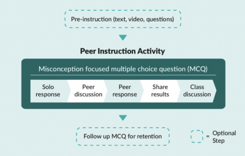
What is peer instruction?
Peer instruction is a structured, collaborative teaching approach. It has been shown to be an effective pedagogy for novice programmers and those studying computer science at a university level because the interactive, cooperative activities help learners to perceive the topics as less stressful and less difficult [2].
Multiple-choice questions (MCQs) and peer conversations about the question answers are at the core of the peer instruction approach. Through talking to each other about MCQs, pupils can deepen their understanding about why a particular concept or fact is correct, and correct any misconceptions.
In England, the Computing curriculum at Key Stage 3 (ages 11–14) introduces learners to some new concepts, such as data representation, and moves learners to text-based programming languages. Towards the end of this Key Stage, learners will make choices about the subjects that they go onto study for GCSEs. These choices are influenced by learners’ attitudes towards the subject, and so we decided to trial whether the peer instruction teaching approach might lead to more positive attitudes towards Computing among girls.
The Peer Instruction intervention
The initial pilot of this trial ran from January to March 2020 with 15 secondary schools. We then used teacher feedback to develop resources to use in a full randomised controlled trial which ran from October 2021 to February 2022 in more than 60 secondary schools in England. Due to the COVID-19 pandemic, we changed our original plan to run face-to-face training and instead developed an online course to train teachers in the peer instruction approach. After taking part in the training, the teachers delivered 12 weeks of Computing lessons in data representation and Python programming. The two six-week units of work covered computing concepts for Key Stage 3 learners such as:
- Understanding how numbers can be represented in binary format
- Understanding how data of various types can be represented and manipulated digitally in the form of binary digits
- Using a text-based programming language to solve a variety of computational problems
The study was run as a randomised controlled trial where participating schools were randomly divided into two groups. Schools in the treatment group used the peer instruction resources, and schools in the control group taught their normal Computing lessons. The independent evaluators from the Behavioural Insights Team used pupil surveys to measure the impact of the resources and supported this with lesson observations and teacher interviews to better understand the themes emerging from the data.
“I think peer instruction lessons are actually better than the normal lessons because you can ask other people around you to help more.”
– Female pupil who took part in the peer instruction lessons (report, p. 45)
Findings from the evaluation
The outcome measures of the peer instruction approach evaluation were quantitative data obtained from Year 8 pupils (aged 12 to 13) via pre- and post-surveys about the pupils’ stated intent to select Computer Science as a GCSE subject, and attitudes towards Computing as captured by the Student Computer Science Attitude Survey (SCSAS). When compared with the control group, the treatment group did not show a statistically significant increase in stated intent or positive attitudes towards Computing. This is a really valuable finding to help us build our understanding of what works in computing education.
The evaluation report contains some useful suggestions on how peer instruction methods could be improved in the secondary classroom:
- Emphasise the importance of the stages of the peer instruction approach throughout the supporting materials. Our support for teachers changed from an in-person training day in stage one to an online course in stage two, and this impacted how much we could model the peer instruction steps that involve pupil discussion. This teaching approach differs from the traditional approach of asking learners to put their hands up to answer questions, and we believe that face-to-face training for teachers would be the best way to explore stage two of peer instruction. The importance of the discussion steps in peer instruction were further emphasised in the report: “The interviewed girls similarly reported that they preferred working in a group (as opposed to answering questions individually) as they were able to hear from people who had different ideas to them and check their answers.” So the discussion steps in peer instruction need careful thought when being delivered.
- It may be useful to combine the peer instruction approach with other strategies. Although only a small number of girls taking part were interviewed, their feedback about the peer instruction lessons was very positive. The evaluation suggests that a multi-faceted approach to addressing gender balance is needed, given that the lack of girls in computing is indicative of a substantive societal issue, which decades of initiatives and research have attempted to address. The evaluators suggested that combining this pedagogy with other strategies, such as linking Computing to real-world problem-solving (another topic we explored in the Gender Balance in Computing programme), may have a cumulatively positive effect.
“Year 8 is too late”
At the start of both the Pair Programming and Peer Instruction projects, pupils were asked the same set of questions about their attitudes towards Computing via the Student Computer Science Attitude Survey (SCSAS). The mean scores from the survey results suggest that there is a small gender gap in attitudes at primary school. Boys feel slightly more confident and interested in Computing than girls. By secondary school, this gap has widened, as shown in the graph below:
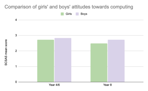
In both projects, pupils were also asked about their intentions to continue studying Computing. In the Pair Programming project, the participating pupils (in Year 4/6) were asked whether they wanted to study Computing in the future, whereas the Year 8 pupils taking part in the Peer Instruction project were asked whether they intended to choose Computer Science as a GCSE subject. We cannot compare these two sets of answers directly, but there is general indication that as girls progress through stages of education, they begin to decide that Computing is not a subject for them. The independent evaluators commented that “it is striking that the gap between genders widens to such an extent over this 2- to 4-year time period, and that the overall proportions of pupils intending to continue to study Computing decreases to such an extent” (p. 15 of the report).
“These findings show a clear difference in attitudes towards learning Computing between primary and secondary learners. It really makes the adage ‘Year 8 is too late’ very true, and it is important to think carefully about what happens between Year 6 and Year 8 to make sure that Computing is a subject which engages all learners.”
– Sue Sentance, Chief Learning Officer, Raspberry Pi Foundation
Want to find out more about peer instruction?
- Download our Big Book of Computing Pedagogy (available as a free online download) and find out more about peer instruction on pages 56 and 57.
- Read the evaluation report of the peer instruction intervention.
- Try the free training course on peer instruction used in this project. This course links to our research materials used by teachers as part of the intervention.
We are very grateful to all the schools, pupils, and teachers who took part in this project. If you would like to stay up-to-date with the Gender Balance in Computing programme, you can sign up to our newsletter. We will also share reports on the other projects within the programme that have explored:
- Pupils’ sense of belonging in Computing
- The links between non-formal and formal Computing
- The impact of using Computing to solve real-world problems
[1] Goode, J., Estrella, R., & Margolis, J. (2008). Lost in Translation: Gender and High School Computer Science. In Cohoon, J, & Aspray, W. (Eds.) Women and Information Technology. Cambridge, MA: The MIT Press. https://doi.org/https://doi.org/10.7551/mitpress/7272.003.0005
[2] Herman, G. L., & Azad, S. (2020, February). A comparison of peer instruction and collaborative problem solving in a computer architecture course. In Proceedings of the 51st ACM Technical Symposium on Computer Science Education. Association for Computing Machinery, New York, NY, USA. pp. 461–467. https://dl.acm.org/doi/10.1145/3328778.3366819
The post A peer instruction approach for engaging girls in the Computing classroom: Study results appeared first on Raspberry Pi.
The Lack Of Native MFA For Active Directory Is A Big Sin For Microsoft
Post Syndicated from Bozho original https://techblog.bozho.net/the-lack-of-native-mfa-for-active-directory-is-a-big-sin-for-microsoft/
Active Directory is dominant in the enterprise world (as well as the public sector). From my observation, the majority of organization rely on Active Directory for their user accounts. While that may be changing in recent years with more advanced and cloud IAM and directory solutions, the landscape in the last two decades is a domination of Microsoft’s Active Directory.
As a result of that dominance, many cyber attacks rely on exploiting some aspects of Active Directory. Whether it would be weaknesses of Kerberos, “pass the ticket”, golden ticket, etc. Standard attacks like password spraying, credential stuffing and other brute forcing also apply, especially if the Exchange web access is enabled. Last, but not least, simply browsing the active directory once authenticated with a compromised account, provides important information for further exploitation (finding other accounts, finding abandoned, but not disabled accounts, finding passwords in description fields, etc).
Basically, having access an authentication endpoint which interfaces the Active Directory allows attackers to gain access and then do lateral movement.
What is the most recommended measures for preventing authentication attacks? Multi-factor authentication. And the sad reality is that Microsoft doesn’t offer native MFA for Active Directory.
Yes, there are things like Microsoft Hello for Business, but that can’t be used in web and email context – it is tied to the Windows machine. And yes, there are third-party options. But they incur additional cost, and are complex to setup and manage. We all know the power of defaults and built-in features in security – it should be readily available and simple in order to have wide adoption.
What Microsoft should have done is introduce standard, TOTP-based MFA and enforce it through native second-factor screens in Windows, Exchange web access, Outlook and others. Yes, that would require Kerberos upgrades, but it is completely feasible. Ideally, it should be enabled by a single click, which would prompt users to enroll their smart phone apps (Google Authenticator, Microsoft Authenticator, Authy or other) on their next successful login. Of course, there may be users without smartphones, and so the option to not enroll for MFA may be available to certain less-privileged AD groups.
By not doing that, Microsoft exposes all on-premise AD deployments to all sorts of authentication attacks mentioned above. And for me that’s a big sin.
Microsoft would say, of course, that their Azure AD supports many MFA options and is great and modern and secure and everything. And that’s true, if you want to chose to migrate to Azure and use Office365. And pay for subscription vs just the Windows Server license. It’s not a secret that Microsoft’s business model is shifting towards cloud, subscription services. And there’s nothing wrong with that. But leaving on-prem users with no good option for proper MFA across services, including email, is irresponsible.
The post The Lack Of Native MFA For Active Directory Is A Big Sin For Microsoft appeared first on Bozho's tech blog.
Freedom: The 8-Track Revolution
Post Syndicated from The History Guy: History Deserves to Be Remembered original https://www.youtube.com/watch?v=Jhj52_fRyB0
Mudge Files Whistleblower Complaint against Twitter
Post Syndicated from Bruce Schneier original https://www.schneier.com/blog/archives/2022/08/mudge-files-whistleblower-complaint-against-twitter.html
Peiter Zatko, aka Mudge, has filed a whistleblower complaint with the SEC against Twitter, claiming that they violated an eleven-year-old FTC settlement by having lousy security. And he should know; he was Twitter’s chief security officer until he was fired in January.
The Washington Post has the scoop (with documents) and companion backgrounder. This CNN story is also comprehensive.
EDITED TO ADD: Another news article. Slashdot thread.
EDITED TO ADD (9/2): More info.
Tetherball Configurations
Post Syndicated from original https://xkcd.com/2663/

Firefox 104 released
Post Syndicated from original https://lwn.net/Articles/905788/
Version
104 of the Firefox browser has been released. The most interesting
new feature, perhaps, is the ability to analyze a web site’s power usage —
but that feature is not available on Linux.
How to export AWS Security Hub findings to CSV format
Post Syndicated from Andy Robinson original https://aws.amazon.com/blogs/security/how-to-export-aws-security-hub-findings-to-csv-format/
AWS Security Hub is a central dashboard for security, risk management, and compliance findings from AWS Audit Manager, AWS Firewall Manager, Amazon GuardDuty, IAM Access Analyzer, Amazon Inspector, and many other AWS and third-party services. You can use the insights from Security Hub to get an understanding of your compliance posture across multiple AWS accounts. It is not unusual for a single AWS account to have more than a thousand Security Hub findings. Multi-account and multi-Region environments may have tens or hundreds of thousands of findings. With so many findings, it is important for you to get a summary of the most important ones. Navigating through duplicate findings, false positives, and benign positives can take time.
In this post, we demonstrate how to export those findings to comma separated values (CSV) formatted files in an Amazon Simple Storage Service (Amazon S3) bucket. You can analyze those files by using a spreadsheet, database applications, or other tools. You can use the CSV formatted files to change a set of status and workflow values to align with your organizational requirements, and update many or all findings at once in Security Hub.
The solution described in this post, called CSV Manager for Security Hub, uses an AWS Lambda function to export findings to a CSV object in an S3 bucket, and another Lambda function to update Security Hub findings by modifying selected values in the downloaded CSV file from an S3 bucket. You use an Amazon EventBridge scheduled rule to perform periodic exports (for example, once a week). CSV Manager for Security Hub also has an update function that allows you to update the workflow, customer-specific notation, and other customer-updatable values for many or all findings at once. If you’ve set up a Region aggregator in Security Hub, you should configure the primary CSV Manager for Security Hub stack to export findings only from the aggregator Region. However, you may configure other CSV Manager for Security Hub stacks that export findings from specific Regions or from all applicable Regions in specific accounts. This allows application and account owners to view their own Security Hub findings without having access to other findings for the organization.
How it works
CSV Manager for Security Hub has two main features:
- Export Security Hub findings to a CSV object in an S3 bucket
- Update Security Hub findings from a CSV object in an S3 bucket
Overview of the export function
The overview of the export function CsvExporter is shown in Figure 1.

Figure 1: Architecture diagram of the export function
Figure 1 shows the following numbered steps:
- In the AWS Management Console, you invoke the CsvExporter Lambda function with a test event.
- The export function calls the Security Hub GetFindings API action and gets a list of findings to export from Security Hub.
- The export function converts the most important fields to identify and sort findings to a 37-column CSV format (which includes 12 updatable columns) and writes to an S3 bucket.
Overview of the update function
To update existing Security Hub findings that you previously exported, you can use the update function CsvUpdater to modify the respective rows and columns of the CSV file you exported, as shown in Figure 2. There are 12 modifiable columns out of 37 (any changes to other columns are ignored), which are described in more detail in Step 3: View or update findings in the CSV file later in this post.
Figure 2: Architecture diagram of the update function

Figure 2 shows the following numbered steps:
- You download the CSV file that the CsvExporter function generated from the S3 bucket and update as needed.
- You upload the CSV file that contains your updates to the S3 bucket.
- In the AWS Management Console, you invoke the CsvUpdater Lambda function with a test event containing the URI of the CSV file.
- CsvUpdater reads the updated CSV file from the S3 bucket.
- CsvUpdater identifies the minimum set of updates and invokes the Security Hub BatchUpdateFindings API action.
Step 1: Use the CloudFormation template to deploy the solution
You can set up and use CSV Manager for Security Hub by using either AWS CloudFormation or the AWS Cloud Development Kit (AWS CDK).
To deploy the solution (AWS CDK)
You can find the latest code in the aws-security-hub-csv-manager GitHub repository, where you can also contribute to the sample code. The following commands show how to deploy the solution by using the AWS CDK. First, the AWS CDK initializes your environment and uploads the AWS Lambda assets to an S3 bucket. Then, you deploy the solution to your account by using the following commands. Replace <INSERT_AWS_ACCOUNT> with your account number, and replace <INSERT_REGION> with the AWS Region that you want the solution deployed to, for example us-east-1.
cdk bootstrap aws://<INSERT_AWS_ACCOUNT>/<INSERT_REGION>
cdk deploy
To deploy the solution (CloudFormation)
- Choose the following Launch Stack button to open the AWS CloudFormation console pre-loaded with the template for this solution:

- In the Parameters section, as shown in Figure 3, enter your values.

Figure 3: CloudFormation template variables
- For What folder for CSV Manager for Security Hub Lambda code, leave the default Code. For What folder for CSV Manager for Security Hub exports, leave the default Findings.
These are the folders within the S3 bucket that the CSV Manager for Security Hub CloudFormation template creates to store the Lambda code, as well as where the findings are exported by the Lambda function.
- For Frequency, for this solution you can leave the default value cron(0 8 ? * SUN *). This default causes automatic exports to occur every Sunday at 8:00 AM local time using an EventBridge scheduled rule. For more information about how to update this value to meet your needs, see Schedule Expressions for Rules in the Amazon CloudWatch Events User Guide.
- The values you enter for the Regions field depend on whether you have configured an aggregation Region in Security Hub.
- If you have configured an aggregation Region, enter only that Region code, for example eu-north-1, as shown in Figure 3.
- If you haven’t configured an aggregation Region, enter a comma-separated list of Regions in which you have enabled Security Hub, for example us-east-1, eu-west-1, eu-west-2.
- If you would like to export findings from all Regions where Security Hub is enabled, leave the Regions field blank. Regions where Security Hub is not enabled will generate a message and will be skipped.
- For What folder for CSV Manager for Security Hub Lambda code, leave the default Code. For What folder for CSV Manager for Security Hub exports, leave the default Findings.
- Choose Next.

The CloudFormation stack deploys the necessary resources, including an EventBridge scheduling rule, AWS System Managers Automation documents, an S3 bucket, and Lambda functions for exporting and updating Security Hub findings.
After you deploy the CloudFormation stack
After you create the CSV Manager for Security Hub stack, you can do the following:
- Perform the export function to write some or all Security Hub findings to a CSV file by following the instructions in Step 2: Export Security Hub findings to a CSV file later in this post.
- Perform a bulk update of Security Hub findings by following the instructions in Step 3: View or update findings in the CSV file later in this post. You can make changes to one or more of the 12 updatable columns of the CSV file, and perform the update function to update some or all Security Hub findings.
Step 2: Export Security Hub findings to a CSV file
You can export Security Hub findings from the AWS Lambda console. To do this, you create a test event and invoke the CsvExporter Lambda function. CsvExporter exports all Security Hub findings from all applicable Regions to a single CSV file in the S3 bucket for CSV Manager for Security Hub.
To export Security Hub findings to a CSV file
- In the AWS Lambda console, find the CsvExporter Lambda function and select it.
- On the Code tab, choose the down arrow at the right of the Test button, as shown in Figure 4, and select Configure test event.
Figure 4: The down arrow at the right of the Test button
- To create an empty test event, on the Configure test event page, do the following:
- Choose Create a new event.
- Enter an event name; in this example we used testEvent.
- For Template, leave the default hello-world.
- For Event JSON, enter the JSON object {} as shown in Figure 5.

Figure 5: Creating an empty test event
- Choose Save to save the empty test event.
- To invoke the Lambda function, choose the Test button, as shown in Figure 6.
Figure 6: Test button to invoke the Lambda function
- On the Execution Results tab, note the following details, which you will need for the next step.
- Locate the CSV object that matches the value of “exportKey” (in this example, DOC-EXAMPLE-OBJECT) in the S3 bucket that matches the value of “bucket” (in this example, DOC-EXAMPLE-BUCKET).


Now you can view or update the findings in the CSV file, as described in the next section.
Step 3: (Optional) Using filters to limit CSV results
In your test event, you can specify any filter that is accepted by the GetFindings API action. You do this by adding a filter key to your test event. The filter key can either contain the word HighActive (which is a predefined filter configured as a default for selecting active high-severity and critical findings, as shown in Figure 8), or a JSON filter object.
Figure 8 depicts an example JSON filter that performs the same filtering as the HighActive predefined filter.
To use filters to limit CSV results
- In the AWS Lambda console, find the CsvExporter Lambda function and select it.
- On the Code tab, choose the down arrow at the right of the Test button, as shown in Figure 7, and select Configure test event.
Figure 7: The down arrow at the right of the Test button
- To create a test event containing a filter, on the Configure test event page, do the following:
- Choose Create a new event.
- Enter an event name; in this example we used filterEvent.
- For Template, select testEvent,
- For Event JSON, enter the following JSON object, as shown in Figure 8.

Figure 8: Test button to invoke the Lambda function
- Choose Save.
- To invoke the Lambda function, choose the Test button as shown in Figure 9.
Figure 9: Test button to invoke the Lambda function
- On the Execution Results tab, note the following details, which you will need for the next step.
- Locate the CSV object that matches the value of “exportKey” (in this example, DOC-EXAMPLE-OBJECT) in the S3 bucket that matches the value of “bucket” (in this example, DOC-EXAMPLE-BUCKET).


The results in this CSV file should be a filtered set of Security Hub findings according to the filter you specified above. You can now proceed to step 4 if you want to view or update findings.
Step 4: View or update findings in the CSV file
You can use any program that allows you to view or edit CSV files, such as Microsoft Excel. The first row in the CSV file are the column names. These column names correspond to fields in the JSON objects that are returned by the GetFindings API action.
Warning: Do not modify the first two columns, Id (column A) or ProductArn (column B). If you modify these columns, Security Hub will not be able to locate the finding to update, and any other changes to that finding will be discarded.
You can locally modify any of the columns in the CSV file, but only 12 columns out of 37 columns will actually be updated if you use CsvUpdater to update Security Hub findings. The following are the 12 columns you can update. These correspond to columns C through N in the CSV file.
| Column name | Spreadsheet column | Description |
| Criticality | C | An integer value between 0 and 100. |
| Confidence | D | An integer value between 0 and 100. |
| NoteText | E | Any text you wish |
| NoteUpdatedBy | F | Automatically updated with your AWS principal user ID. |
| CustomerOwner* | G | Information identifying the owner of this finding (for example, email address). |
| CustomerIssue* | H | A Jira issue or another identifier tracking a specific issue. |
| CustomerTicket* | I | A ticket number or other trouble/problem tracking identification. |
| ProductSeverity** | J | A floating-point number from 0.0 to 99.9. |
| NormalizedSeverity** | K | An integer between 0 and 100. |
| SeverityLabel | L | One of the following:
|
| VerificationState | M | One of the following:
|
| Workflow | N | One of the following:
|
* These columns are stored inside the UserDefinedFields field of the updated findings. The column names imply a certain kind of information, but you can put any information you wish.
** These columns are stored inside the Severity field of the updated findings. These values have a fixed format and will be rejected if they do not meet that format.
Columns with fixed text values (L, M, N) in the previous table can be specified in mixed case and without underscores—they will be converted to all uppercase and underscores added in the CsvUpdater Lambda function. For example, “false positive” will be converted to “FALSE_POSITIVE”.
Step 5: Create a test event and update Security Hub by using the CSV file
If you want to update Security Hub findings, make your changes to columns C through N as described in the previous table. After you make your changes in the CSV file, you can update the findings in Security Hub by using the CSV file and the CsvUpdater Lambda function.
Use the following procedure to create a test event and run the CsvUpdater Lambda function.
To create a test event and run the CsvUpdater Lambda function
- In the AWS Lambda console, find the CsvUpdater Lambda function and select it.
- On the Code tab, choose the down arrow to the right of the Test button, as shown in Figure 10, and select Configure test event.
Figure 10: The down arrow to the right of the Test button
- To create a test event as shown in Figure 11, on the Configure test event page, do the following:
- Choose Create a new event.
- Enter an event name; in this example we used testEvent.
- For Template, leave the default hello-world.
- For Event JSON, enter the following:
Replace <s3ObjectUri> with the full URI of the S3 object where the updated CSV file is located.
Replace <aggregationRegionName> with your Security Hub aggregation Region, or the primary Region in which you initially enabled Security Hub.
Figure 11: Create and save a test event for the CsvUpdater Lambda function
- Choose Save.
- Choose the Test button, as shown in Figure 12, to invoke the Lambda function.
Figure 12: Test button to invoke the Lambda function
- To verify that the Lambda function ran successfully, on the Execution Results tab, review the results for “message”: “Success”, as shown in the following example. Note that the results may be thousands of lines long.
The processed array lists every successfully updated finding by Id and ProductArn.
If any of the findings were not successfully updated, their Id and ProductArn appear in the unprocessed array. In the previous example, no findings were unprocessed.
The value s3://DOC-EXAMPLE-BUCKET/DOC-EXAMPLE-OBJECT is the URI of the S3 object from which your updates were read.


Cleaning up
To avoid incurring future charges, first delete the CloudFormation stack that you deployed in Step 1: Use the CloudFormation template to deploy the solution. Next, you need to manually delete the S3 bucket deployed with the stack. For instructions, see Deleting a bucket in the Amazon Simple Storage Service User Guide.
Conclusion
In this post, we showed you how you can export Security Hub findings to a CSV file in an S3 bucket and update the exported findings by using CSV Manager for Security Hub. We showed you how you can automate this process by using AWS Lambda, Amazon S3, and AWS Systems Manager. Full documentation for CSV Manager for Security Hub is available in the aws-security-hub-csv-manager GitHub repository. You can also investigate other ways to manage Security Hub findings by checking out our blog posts about Security Hub integration with Amazon OpenSearch Service, Amazon QuickSight, Slack, PagerDuty, Jira, or ServiceNow.
If you have feedback about this post, submit comments in the Comments section below. If you have questions about this post, start a new thread on the Security Hub re:Post. To learn more or get started, visit AWS Security Hub.
Want more AWS Security news? Follow us on Twitter.
Avoiding Smash and Grab Under the SEC’s Proposed Cyber Rule
Post Syndicated from Harley Geiger original https://blog.rapid7.com/2022/08/23/avoiding-smash-and-grab-under-the-secs-proposed-cyber-rule/

The SEC recently proposed a regulation to require all public companies to report cybersecurity incidents within four days of determining that the incident is material. While Rapid7 generally supports the proposed rule, we are concerned that the rule requires companies to publicly disclose a cyber incident before the incident has been contained or mitigated. This post explains why this is a problem and suggests a solution that still enables the SEC to drive companies toward disclosure.
(Terminology note: “Public companies” refers to companies that have stock traded on public US exchanges, and “material” means information that “there is a substantial likelihood that a reasonable shareholder would consider it important.” “Containment” aims to prevent a cyber incident from spreading. Containment is part of “mitigation,” which includes actions to reduce the severity of an event or the likelihood of a vulnerability being exploited, though may fall short of full remediation.)
In sum: The public disclosure of material cybersecurity incidents prior to containment or mitigation may cause greater harm to investors than a delay in public disclosure. We propose that the SEC provide an exemption to the proposed reporting requirements, enabling a company to delay public disclosure of an uncontained or unmitigated incident if certain conditions are met. Additionally, we explain why we believe other proposed solutions may not meet the SEC’s goals of transparency and avoidance of harm to investors.
Distinguished by default public disclosure
The purpose of the SEC’s proposed rule is to help enable investors to make informed investment decisions. This is a reflection of the growing importance of cybersecurity to corporate governance, risk assessment, and other key factors that stockholders weigh when investing. With the exception of reporting unmitigated incidents, Rapid7 largely supports this perspective.
The SEC’s proposed rule would (among other things) require companies to disclose material cyber incidents on Form 8-K, which are publicly available via the EDGAR system. Crucially, the SEC’s proposed rule makes no distinction between public disclosure of incidents that are contained or mitigated and incidents that are not yet contained or mitigated. While the public-by-default nature of the disclosure creates new problems, it also aligns with the SEC’s purpose in proposing the rule.
In contrast to the SEC’s proposed rule, the purpose of most other incident reporting regulations is to strengthen cybersecurity – a top global policy priority. As such, most other cyber incident reporting regulators (such as CISA, NERC, FDIC, Fed. Reserve, OCC, NYDFS, etc.) do not typically make incident reports public in a way that identifies the affected organization. In fact, some regulations (such as CIRCIA and the 2021 TSA pipeline security directive) classify company incident reports as sensitive information exempt from FOIA.
Beyond regulations, established cyber incident response protocol is to avoid tipping off an attacker until the incident is contained and the risk of further damage has been mitigated. See, for example, CISA’s Incident Response Playbook (especially sections on opsec) and NIST’s Computer Security Incident Handling Guide (especially Section 2.3.4). For similar reasons, it is commonly the goal of coordinated vulnerability disclosure practices to avoid, when possible, public disclosure of a vulnerability until the vulnerability has been mitigated. See, for example, the CERT Guide to Coordinated Disclosure.
While it may be reasonable to require disclosure of a contained or mitigated incident within four days of determining its materiality, a strict requirement for public disclosure of an unmitigated or ongoing incident is likely to expose companies and investors to additional danger. Investors are not the only group that may act on a cyber incident report, and such information may be misused.
Smash and grab harms investors and misprices securities
Cybercriminals often aim to embed themselves in corporate networks without the company knowing. Maintaining a low profile lets attackers steal data over time, quietly moving laterally across networks, steadily gaining greater access – sometimes over a period of years. But when the cover is blown and the company knows about its attacker? Forget secrecy, it’s smash and grab time.
Public disclosure of an unmitigated or uncontained cyber incident will likely lead to attacker behaviors that cause additional harm to investors. Note that such acts would be in reaction to the public disclosure of an unmitigated incident, and not a natural result of the original attack. For example:
- Smash and grab: A discovered attacker may forgo stealth and accelerate data theft or extortion activities, causing more harm to the company (and therefore its investors). Consider this passage from the MS-ISAC’s 2020 Ransomware Guide: “Be sure [to] avoid tipping off actors that they have been discovered and that mitigation actions are being undertaken. Not doing so could cause actors to move laterally to preserve their access [or] deploy ransomware widely prior to networks being taken offline.”
- Scorched earth: A discovered attacker may engage in anti-forensic activity (such as deleting logs), hindering post-incident investigations and intelligence sharing that could prevent future attacks that harm investors. From CISA’s Playbook: “Some adversaries may actively monitor defensive response measures and shift their methods to evade detection and containment.”
- Pile-on: Announcing that a company has an incident may cause other attackers to probe the company and discover the vulnerability or attack vector from the original incident. If the incident is not yet mitigated, the copycat attackers can cause further harm to the company (and therefore its investors). From the CERT Guide to CVD: “Mere knowledge of a vulnerability’s existence in a feature of some product is sufficient for a skillful person to discover it for themselves. Rumor of a vulnerability draws attention from knowledgeable people with vulnerability finding skills — and there’s no guarantee that all those people will have users’ best interests in mind.”
- Supply chain: Public disclosure of an unmitigated cybersecurity incident may alert attackers to a vulnerability that is present in other companies, the exploitation of which can harm investors in those other companies. Publicly disclosing “the nature and scope” of material incidents within four business days risks exposing enough detail of an otherwise unique zero-day to encourage rediscovery and reimplementation by other criminal and espionage groups against other organizations. For example, fewer than 100 organizations were actually exploited through the Solarwinds supply chain attack, but up to 18,000 organizations were at risk.
In addition, requiring public disclosure of uncontained or unmitigated cyber incidents may result in mispricing the stock of the affected company. By contradicting best practices for cyber incident response and inviting new attacks, the premature public disclosure of an uncontained or unmitigated incident may provide investors with an inaccurate measure of the company’s true ability to respond to cybersecurity incidents. Moreover, a premature disclosure during the incident response process may result in investors receiving inaccurate information about the scope or impact of the incident.
Rapid7 is not opposed to public disclosure of unmitigated vulnerabilities or incidents in all circumstances, and our security researchers publicly disclose vulnerabilities when necessary. However, public disclosure of unmitigated vulnerabilities typically occurs after failure to mitigate (such as due to inability to engage the affected organization), or when users should take defensive measures before mitigation because ongoing exploitation of the vulnerability “in the wild” is actively harming users. By contrast, the SEC’s proposed rule would rely on a public disclosure requirement on a restrictive timeline in nearly all cases, creating the risk of additional harm to investors that can outweigh the benefits of public disclosure.
Proposed solution
Below, we suggest a solution that we believe achieves the SEC’s ultimate goal of investor protection by requiring timely disclosure of cyber incidents and simultaneously avoiding the unnecessary additional harm to investors that may result with premature public disclosure.
Specifically, we suggest that the proposed rule remains largely the same — i.e., the SEC continues to require that companies determine whether the incident is material as soon as practicable after discovery of the cyber incident, and file a report on Form 8-K four days after the materiality determination under normal circumstances. However, we propose that the rule be revised to also provide companies with a temporary exemption from public disclosure if each of the below conditions are met:
- The incident is not yet contained or otherwise mitigated to prevent additional harm to the company and its investors;
- The company reasonably believes that public disclosure of the uncontained or unmitigated incident may cause substantial additional harm to the company, its investors, or other public companies or their investors;
- The company reasonably believes the incident can be contained or mitigated in a timely manner; and
- The company is actively engaged in containing or mitigating the incident in a timely manner.
The determination of the applicability of the aforementioned exception may be made simultaneously to the determination of materiality. If the exception applies, the company may delay public disclosure until such time that any of the conditions are no longer occurring, at which point, they must publicly disclose the cyber incident via Form 8-K, no later than four days after the date on which the exemption is no longer applicable. The 8-K disclosure could note that, prior to filing the 8-K, the company relied on the exemption from disclosure. Existing insider trading restrictions would, of course, continue to apply during the public disclosure delay.
If an open-ended delay in public disclosure for containment or mitigation is unacceptable to the SEC, then we suggest that the exemption only be available for 30 days after the determination of materiality. In our experience, the vast majority of incidents can be contained and mitigated within that time frame. However, cybersecurity incidents can vary greatly, and there may nonetheless be rare outliers where the mitigation process exceeds 30 days.
Drawbacks of other solutions
Rapid7 is aware of other solutions being floated to address the problem of public disclosure of unmitigated cyber incidents. However, these carry drawbacks that do not align with the purpose of the SEC rule or potentially don’t make sense for cybersecurity. For example:
- AG delay: The SEC’s proposed rule considers allowing a delay in reporting the incident when the Attorney General (AG) determines the delay is in the interest of national security. This is an appropriate delay, but insufficient on its own. This AG delay would apply to a very small fraction of major cyber incidents and not prevent the potential harms described above in the vast majority of cases.
- Law enforcement delay: The SEC’s proposed rule considers, and then rejects, a delay when incident reporting would hinder a law enforcement investigation. We believe this too would be an appropriate delay, to ensure law enforcement can help prevent future cyber incidents that would harm investors. However, it is unclear if this delay would be triggered in many cases. First, the SEC’s proposed timeframe (four days after concluding the incident is material) poses a tight turnaround for law enforcement to start a new investigation or add to an existing investigation, determine how disclosure might impact the investigation, and then request delay from the SEC. Second, law enforcement agencies already have investigations opened against many cybercriminal groups, so public disclosure of another incident may not make a significant difference in the investigation, even if public disclosure of the incident would cause harm. Although a law enforcement delay would be used more than the AG delay, we still anticipate it would apply to only a fraction of incidents.
- Vague disclosures: Another potential solution is to continue to require public companies to disclose unmitigated cyber incidents on the proposed timeline, but to allow the disclosures to be so vague that it is unclear whether the incident has been mitigated. Yet an attacker embedded in a company network is unlikely to be fooled by a vague incident report from the same company, and even a vague report could encourage new attackers to try to get a foothold in. In addition, very vague disclosures are unlikely to be useful for investor decision-making.
- Materiality after mitigation: Another potential solution is to require a materiality determination only after the incident has been mitigated. However, this risks unnecessary delays in mitigation to avoid triggering the deadline for disclosure, even for incidents that could be mitigated within the SEC’s proposed timeline. Although containment or mitigation of an incident is important prior to public disclosure of the incident, completion of mitigation is not necessarily a prerequisite to determining the seriousness (i.e., materiality) of an incident.
Balancing risks and benefits of transparency
The SEC has an extensive list of material information that it requires companies to disclose publicly on 8-Ks – everything from bankruptcies to mine safety. However, public disclosure of any of these other items is not likely to prompt new criminal actions that bring additional harm to investors. Public disclosure of unmitigated cyber incidents poses unique risks compared with other disclosures and should be considered in that light.
The SEC has long been among the most forward-looking regulators on cybersecurity issues. We thank them for the acknowledgement of the significance of cybersecurity to corporate management, and for taking the time to listen to feedback from the community. Rapid7’s feedback is that we agree on the usefulness of disclosure of material cybersecurity incidents, but we encourage SEC to ensure its public reporting requirement avoids undermining its own goals and providing more opportunities for attackers.
Additional reading:
Reduce network traffic costs of your Amazon MSK consumers with rack awareness
Post Syndicated from Todd McGrath original https://aws.amazon.com/blogs/big-data/reduce-network-traffic-costs-of-your-amazon-msk-consumers-with-rack-awareness/
Amazon Managed Streaming for Apache Kafka (Amazon MSK) runs Apache Kafka clusters for you in the cloud. Although using cloud services means you don’t have to manage racks of servers any more, we take advantage of rack aware features in Apache Kafka to spread risk across AWS Availability Zones and increase availability of Amazon MSK services. Apache Kafka brokers have been rack aware since version 0.10. As the name implies, rack awareness provides a mechanism by which brokers can be configured to be aware of where they are physically located. We can use the broker.rack configuration variable to assign each broker a rack ID.
Why would a broker want to know where it’s physically located? Let’s explore two primary reasons. The first original reason revolves around designing for high availability (HA) and resiliency in Apache Kafka. The next reason, starting in Apache Kafka 2.4, can be utilized for cutting costs of your cross-Availability Zone traffic from consumer applications.
In this post, we review the HA and resiliency reason in Apache Kafka and Amazon MSK, then we dive deeper into how to reduce the costs of cross-Availability Zone traffic with rack aware consumers.
Rack awareness overview
The design decision for implementing rack awareness is actually quite simple, so let’s start with the key concepts. Because Apache Kafka is a distributed system, resiliency is a foundational construct that must be addressed. In other words, in a distributed system, one or more broker nodes going offline is a given and must be accounted for when running in production.
In Apache Kafka, one way to plan for this inevitability is through data replication. You can configure Apache Kafka with the topic replication factor. This setting indicates how many copies of the topic’s partition data should be maintained across brokers. A replication factor of 3 indicates the topic’s partitions should be stored on at least three brokers, as illustrated in the following diagram.
For more information on replication in Apache Kafka, including relevant terminology such as leader, replica, and followers, see Replication.
Now let’s take this a step further.
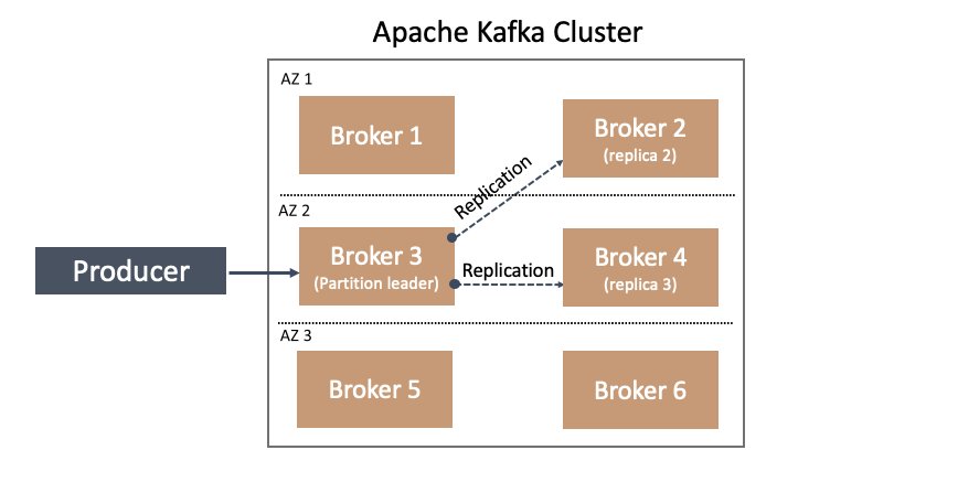
With rack awareness, Apache Kafka can choose to balance the replication of partitions on brokers across different racks according to the replication factor value. For example, in a cluster with six brokers configured with three racks (two brokers in each rack), and a topic replication factor of 3, replication is attempted across all three racks—a leader partition is on a broker in one rack, with replication to the other two brokers in each of the other two racks.
This feature becomes especially interesting when disaster planning for an Availability Zone going offline. How do we plan for HA in this case? Again, the answer is found in rack awareness. If we configure our broker’s broker.rack config setting based on the Availability Zone (or data center location) in which it resides for example, we can be resilient to Availability Zone failures. How does this work? We can build upon the previous example—in a six-node Kafka cluster deployed across three Availability Zones, two nodes are in each Availability Zone and configured with a broker.rack according to their respective Availability Zone. Therefore, a replication factor of 3 is attempted to store a copy of partition data in each Availability Zone. This means a copy of your topic’s data resides in each Availability Zone, as illustrated in the following diagram.

One of the many benefits of choosing to run your Apache Kafka workloads in Amazon MSK is the broker.rack variable on each broker is set automatically according to the Availability Zone in which it is deployed. For example, when you deploy a three-node MSK cluster across three Availability Zones, each node has a different broker.rack setting. Or, when you deploy a six-node MSK cluster across three Availability Zones, you have a total of three unique broker.rack values.
Additionally, a noteworthy benefit of choosing Amazon MSK is that replication traffic across Availability Zones is included with service. You’re not charged for broker replication traffic that crosses Availability Zone boundaries!
In this section, we covered the first reason for being Availability Zone aware: data produced is spread across all the Availability Zones for the cluster, improving durability and availability when there are issues at the Availability Zone level.
Next, let’s explore a second use of rack awareness—how to use it to cut network traffic costs of Kafka consumers.
Starting in Apache Kafka 2.4, KIP-392 was implemented to allow consumers to fetch from the closest replica.
Before closest replica fetching was allowed, all consumer traffic went to the leader of a partition, which could be in a different rack, or Availability Zone, than the client consuming data. But with capability from KIP-392 starting in Apache Kafka 2.4, we can configure our Kafka consumers to read from the closest replica brokers rather than the partition leader. This opens up the potential to avoid cross-Availability Zone traffic costs if a replica follower resides in the same Availability Zone as the consuming application. How does this happen? It’s built on the previously described rack awareness functionality in Apache Kafka brokers and extended to consumers.
Let’s cover a specific example of how to implement this in Amazon MSK and Kafka consumers.
Implement fetch from closest replica in Amazon MSK
In addition to needing to deploy Apache Kafka 2.4 or above (Amazon MSK 2.4.1.1 or above), we need to set two configurations.
In this example, I’ve deployed a three-broker MSK cluster across three Availability Zones, which means one broker resides in each Availability Zone. In addition, I’ve deployed an Amazon Elastic Compute Cloud (Amazon EC2) instance in one of these Availability Zones. On this EC2 instance, I’ve downloaded and extracted Apache Kafka, so I can use the command line tools available such as kafka-configs.sh and kafka-topics.sh in the bin/ directory. It’s important to keep this in mind as we progress through the following sections of configuring Amazon MSK, and configuring and verifying the Kafka consumer.
For your convenience, I’ve provided an AWS CloudFormation template for this setup in the Resources section at the end of this post.
Amazon MSK configuration
There is one broker configuration and one consumer configuration that we need to modify in order to allow consumers to fetch from the closest replica. These are broker.rack on the consumers and replica.selector.class on the brokers.
As previously mentioned, Amazon MSK automatically sets a broker’s broker.rack setting according to Availability Zone. Because we’re using Amazon MSK in this example, this means the broker.rack configuration on each broker is already configured for us, but let’s verify that.
We can confirm the broker.rack setting in a few different ways. As one example, we can use the kafka-configs.sh script from my previously mentioned EC2 instance:
Depending on our environment, we should receive something similar to the following result:
Note that BOOTSTRAP is just an environment variable set to my cluster’s bootstrap server connection string. I set it previously with export BOOTSTRAP=<cluster specific>;
For example: export BOOTSTRAP=b-1.myTestCluster.123z8u.c2.kafka.us-east-1.amazonaws.com:9092,b-2.myTestCluster.123z8u.c2.kafka.us-east-1.amazonaws.com:9092
For more information on bootstrap servers, refer to Getting the bootstrap brokers for an Amazon MSK cluster.
From the command results, we can see broker.rack is set to use1-az4 for broker 1. The value use1-az4 is determined from Availability Zone to Availability Zone ID mapping. You can view this mapping on the Amazon Virtual Private Cloud (Amazon VPC) console on the Subnets page, as shown in the following screenshot.
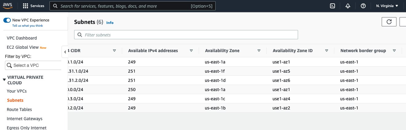
In the preceding screenshot, we can see the Availability Zone ID use1-az4. We note this value for later use in our consumer configuration changes.
The broker setting we need to set is replica.selector.class. In this case, the default value for the configuration in Amazon MSK is null. See the following code:
This results in the following:
That’s ok, because Amazon MSK allows replica.selector.class to be overridden. For more information, refer to Custom MSK configurations.
To override this setting, we need to associate a cluster configuration with this key set to org.apache.kafka.common.replica.RackAwareReplicaSelector. For example, I’ve updated and applied the configuration of the MSK cluster used in this post with the following:
The following screenshot shows the configuration.
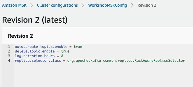
To learn more about applying cluster configurations, see Amazon MSK configuration.
After updating the cluster’s configuration with this configuration, we can verify it’s active in the brokers with the following code:
We get the following results:
With these two broker settings in place, we’re ready to move on to the consumer configuration.
Kafka consumer configuration and verification
In this section, we cover an example of running a consumer that is rack aware vs. one that is not. We verify by examining log files in order to compare the results of different configuration settings.
To perform this comparison, let’s create a topic with six partitions and replication factor of 3:
A replication factor of 3 means the leader partition is in one Availability Zone, while the two replicas are distributed across each remaining Availability Zone. This provides a convenient setup to test and verify our consumer because the consumer is deployed in one of these Availability Zones. This allows us to test and confirm that the consumer never crosses Availability Zone boundaries to fetch because either the leader partition or replica copy is always available from the broker in the same Availability Zone as the consumer.
Let’s load sample data into the order topic using the MSK Data Generator with the following configuration:
How to use the MSK Data Generator is beyond the scope of this post, but we generate sample data to the order topic with a random key (Internet.uuid) and key pair values of product_id, quantity, and customer_id. For our purposes, it’s important the generated key is random enough to ensure the data is evenly distributed across partitions.
To verify our consumer is reading from the closest replica, we need to turn up the logging. Because we’re using the bin/kafka-console-consumer.sh script included with Apache Kafka distribution, we can update the config/tools-log4j.properties file to influence the logging of scripts run in the bin/ directory, including kafka-console-consumer.sh. We just need to add one line:
The following code is the relevant portion from my config/tools-log4j.properties file:
Now we’re ready to test and verify from a consumer.
Let’s consume without rack awareness first:
We get results such as the following:
We get rack: values as use1-az2, use1-az4, and use1-az1. This will vary for each cluster.
This is expected because we’re generating data evenly across the order topic partitions and haven’t configured kafka-console-consumer.sh to fetch from followers yet.
Let’s stop this consumer and rerun it to fetch from the closest replica this time. The EC2 instance in this example is located in Availability Zone us-east-1, which means the Availability Zone ID is use1-az1, as previously discussed. To set this in our consumer, we need to set the client.rack configuration property as shown when running the following command:
Now, the log results show a difference:
For each log line, we now have two rack: values. The first rack: value shows the current leader, the second rack: shows the rack that is being used to fetch messages.
For a specific example, consider the following line from the preceding example code:
The leader is identified as rack: use1-az2, but the fetch request is sent to use1-az1 as indicated by to node b-3.mskcluster-msk.jcojml.c23.kafka.us-east-1.amazonaws.com:9092 (id: 3 rack: use1-az1) (org.apache.kafka.clients.consumer.internals.Fetcher).
You’ll see something similar in all other log lines. The fetch is always to the broker in use1-az1.
And there we have it! We’re consuming from the closest replica.
Conclusion
With closest replica fetch, you can save as much as two-thirds of your cross-Availability Zone traffic charges when consuming from Kafka topics, because your consumers can read from replicas in the same Availability Zone instead of having to cross Availability Zone boundaries to read from the leader. In this post, we provided a background on Apache Kafka rack awareness and how Amazon MSK automatically sets brokers to be rack aware according to Availability Zone deployment. Then we demonstrated how to configure your MSK cluster and consumer clients to take advantage of rack awareness and avoid cross-Availability Zone network charges.
Resources
You can use the following CloudFormation template to create the example MSK cluster and EC2 instance with Apache Kafka downloaded and extracted. Note that this template requires the described WorkshopMSKConfig custom MSK configuration to be pre-created before running the template.
About the author
 Todd McGrath is a data streaming specialist at Amazon Web Services where he advises customers on their streaming strategies, integration, architecture, and solutions. On the personal side, he enjoys watching and supporting his 3 teenagers in their preferred activities as well as following his own pursuits such as fishing, pickleball, ice hockey, and happy hour with friends and family on pontoon boats. Connect with him on LinkedIn.
[$] The container orchestrator landscape
Post Syndicated from original https://lwn.net/Articles/905164/
Docker and other container
engines can greatly simplify many aspects of deploying a server-side
application, but numerous applications consist of more than one container.
Managing a group of containers only gets harder as additional applications
and services are deployed; this has led to the development of a class of
tools called container orchestrators. The best-known of these by far is Kubernetes; the history of container
orchestration can
be divided into what came before it and what came after.
Why We Get Resilience Wrong and The Surprising Science of Real Toughness | Talks at Google
Post Syndicated from Talks at Google original https://www.youtube.com/watch?v=ChDYRIbkz_c
How to Back Up Veeam to the Cloud
Post Syndicated from Kari Rivas original https://www.backblaze.com/blog/how-to-back-up-veeam-to-the-cloud/

Backups are your best defense against ransomware and other types of data loss. Thankfully it is quick and easy to back up all your Veeam data to Backblaze B2 Cloud Storage within minutes—and we have the videos to prove it!
What is Veeam?
Veeam is well-respected backup and disaster recovery software that works across many platforms and hardware/software configurations. Founded in 2006, Veeam Software is a U.S.-based company that operates in over 180 countries and has 400,000 customers—many of them Fortune 500 companies.
The Veeam and Backblaze B2 Cloud Storage Integration
Backblaze has partnered with Veeam to deliver the most reliable, affordable, and secure data protection and cloud storage target for your data. Veeam Backup & Replication provides modern data protection for your cloud, virtual, and physical workloads to solve your challenges around backup, recovery, archive, disaster recovery, and ransomware.
With a transparent pricing model that is a fraction of the competitors’ cost, Backblaze B2 Cloud Storage helps you plan your budget effectively and store more than four times the restore points you could otherwise. With Backblaze B2 as your cloud tier storage destination in Veeam, you can store your data for $5/TB per month with no minimum retention requirement, tiers, or hidden fees.
Additionally, Backblaze is certified as Veeam Ready—Object and Veeam Ready—Object with Immutability. Immutability is an important part of protecting backups from threats such as ransomware or stolen credentials because it allows you to protect objects from being changed, deleted, manipulated, copied, or encrypted for a specified, user-defined time period. Even better, Backblaze does not charge an extra fee for the use of the object lock feature.
How Does Veeam Work with Backblaze B2 Cloud Storage?
Backblaze is a proud partner of Veeam and is fully compatible with Veeam Cloud Tier. Using Backblaze B2’s S3-compatible API, you can set B2 Cloud Storage as your Cloud Tier in Veeam’s Scale-Out Backup Repository.
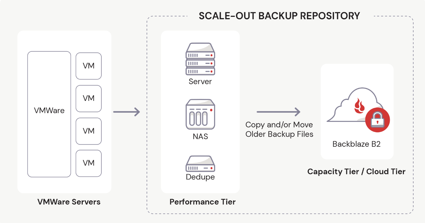
In Veeam v11 and earlier versions, you must first establish the Performance Tier, or Local Repository, before you can set up the Cloud Tier.
If you’ve been using Veeam, you probably already know how to add a local storage repository to Veeam. However, if you are one of our B2 users who are exploring this partnership for the first time, we have a video to guide you through the process. Watch as Greg Hamer, Senior Developer Evangelist, demonstrates how to set up the Local Repository in just a few minutes. If your Local Repository is already configured, then you’re ready to proceed to cloud backup!
Steps to Back Up Your Data with Veeam and Cloud Storage
To make things easy, we have created a video about How to Back Up Veeam to the Cloud. In the video, Greg demonstrates how you can securely store your Veeam data in just 20 minutes.
If you’re not a visual learner, you can easily back up all of your Veeam data to Backblaze’s B2 Cloud Storage using the five easy steps below.
Step 1: Create a Backblaze Account
First, you need to set up a Backblaze account. If you already have a Backblaze account, you’re all set and can move on to step two. Otherwise, visit Backblaze’s Veeam page and click the Start Now button to create one.
The Start Now button will take you to a simple sign-up form where you only have to enter your email address and a password. Don’t worry about setting up billing just yet. You have 10GB of free space to test drive B2 Cloud Storage before you have to set up any billing information.
Once you successfully create a new account, you will create a bucket to store your data in, then collect and save some information from your Backblaze dashboard to use later.
Step 2: Create a Backblaze B2 Bucket and Set Up an Application Key
A “bucket” is a container that holds your files uploaded by your Veeam software to Backblaze B2 Cloud Storage. When configuring your bucket, you will give it a unique name, choose whether it’s private or public (most customers choose private buckets), and turn on Object Lock to secure your files and make them immutable. (This is an important security step you won’t want to miss.)
Each bucket is associated with a name and an S3 Endpoint. You should jot down this Endpoint to use later in Veeam to connect with Backblaze.
Before you exit the Backblaze console, you will set up an Application Key that allows Veeam to connect to and access your storage bucket securely. You give the Application Key a name and make some additional choices to finish setting it up. Finally, you will jot down some details for the Application Key, such as keyID, keyName, and applicationKey, which is essentially a passcode for the key. Be sure to write these down immediately after creating the key, or you won’t be able to access it in plaintext again.
Step 3: Add Backblaze B2 Cloud Storage as a Cloud Tier Repository in Veeam
Switching over to the Veeam console, you will log into your software and create a Cloud Tier repository to interface with Backblaze B2 Cloud Storage.
Before you do that, however, you need to have a local repository created. The tutorial assumes that you have one already and have been using Veeam to backup locally.
To set up your cloud tier, you will follow a few simple steps:
- Choose your object storage type.
- Give it a name.
- Enter your Backblaze S3 Endpoint value.
You will also be prompted to enter your credentials, which is the Application Key information you’ve already set up when you created your Backblaze B2 Bucket. Before exiting that area, Veeam will test the connection to ensure it can reach your Bucket. The final stage in this step allows you to turn on Object Lock to keep your backup files safe.
Step 4: Create the Scale-Out Backup Repository in Veeam
Still working within the Veeam console, you will also set up a scale-out repository to handle backup data load. During this step, you will name your Veeam Scale-Out repository, choose a few options, select the Cloud Tier repository you just created in step three, and ensure that your files are backed up immediately.
Step 5: Create a Backup Job in Veeam
The final stage of our backup tutorial walks you through the process of setting up a backup job. You will continue working in Veeam to create a new backup job using cloud storage. In the video we show you a Virtual Machine backup, but you can create several other types of backup jobs as needed. You can then name your backup job, add the files you want to backup, and choose where you want to save them (in this case, the Scale-Out repository we just created).
You also have options to optimize storage and schedule your backup job to run as often as you like. Then, you can test it immediately to see how it goes.
We hope this video guide and brief explanation were useful in helping you get the most out of both Veeam and Backblaze. If you have thoughts for topics on future videos, sound off in the comments. And be sure to subscribe to our YouTube channel for more great content!
The post How to Back Up Veeam to the Cloud appeared first on Backblaze Blog | Cloud Storage & Cloud Backup.
Security updates for Tuesday
Post Syndicated from original https://lwn.net/Articles/905730/
Security updates have been issued by Oracle (kernel and kernel-container), SUSE (bluez, gimp, rubygem-rails-html-sanitizer, systemd-presets-common-SUSE, and u-boot), and Ubuntu (libxslt).
Signal Phone Numbers Exposed in Twilio Hack
Post Syndicated from Bruce Schneier original https://www.schneier.com/blog/archives/2022/08/signal-phone-numbers-exposed-in-twilio-hack.html
Twilio was hacked earlier this month, and the phone numbers of 1,900 Signal users were exposed:
Here’s what our users need to know:
- All users can rest assured that their message history, contact lists, profile information, whom they’d blocked, and other personal data remain private and secure and were not affected.
- For about 1,900 users, an attacker could have attempted to re-register their number to another device or learned that their number was registered to Signal. This attack has since been shut down by Twilio. 1,900 users is a very small percentage of Signal’s total users, meaning that most were not affected.
We are notifying these 1,900 users directly, and prompting them to re-register Signal on their devices.
If you were not notified, don’t worry about it. But it does bring up the old question: Why does Signal require a phone number to use? It doesn’t have to be that way.
Deploy and manage OpenAPI/Swagger RESTful APIs with the AWS Cloud Development Kit
Post Syndicated from Luke Popplewell original https://aws.amazon.com/blogs/devops/deploy-and-manage-openapi-swagger-restful-apis-with-the-aws-cloud-development-kit/
This post demonstrates how AWS Cloud Development Kit (AWS CDK) Infrastructure as Code (IaC) constructs and AWS serverless technology can be used to build and deploy a RESTful Application Programming Interface (API) defined in the OpenAPI specification. This post uses an example API that describes Widget resources and demonstrates how to use an AWS CDK Pipeline to:
- Deploy a RESTful API stage to Amazon API Gateway from an OpenAPI specification.
- Build and deploy an AWS Lambda function that contains the API functionality.
- Auto-generate API documentation and publish it to an Amazon Simple Storage Service (Amazon S3)-hosted website served by the Amazon CloudFront content delivery network (CDN) service. This provides technical and non-technical stakeholders with versioned, current, and accessible API documentation.
- Auto-generate client libraries for invoking the API and deploy them to AWS CodeArtifact, which is a fully-managed artifact repository service. This allows API client development teams to integrate with different versions of the API in different environments.
The diagram shown in the following figure depicts the architecture of the AWS services and resources described in this post.
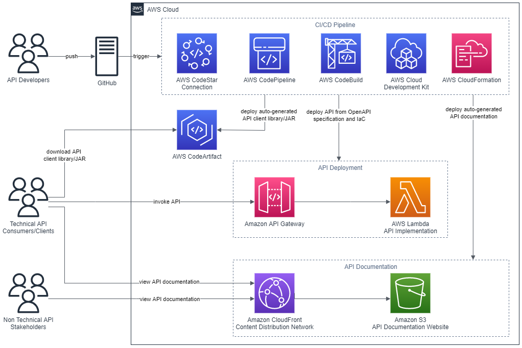
Figure 1 – Architecture
The code that accompanies this post, written in Java, is available here.
Background
APIs must be understood by all stakeholders and parties within an enterprise including business areas, management, enterprise architecture, and other teams wishing to consume the API. Unfortunately, API definitions are often hidden in code and lack up-to-date documentation. Therefore, they remain inaccessible for the majority of the API’s stakeholders. Furthermore, it’s often challenging to determine what version of an API is present in different environments at any one time.
This post describes some solutions to these issues by demonstrating how to continuously deliver up-to-date and accessible API documentation, API client libraries, and API deployments.
AWS CDK
The AWS CDK is a software development framework for defining cloud IaC and is available in multiple languages including TypeScript, JavaScript, Python, Java, C#/.Net, and Go. The AWS CDK Developer Guide provides best practices for using the CDK.
This post uses the CDK to define IaC in Java which is synthesized to a cloud assembly. The cloud assembly includes one to many templates and assets that are deployed via an AWS CodePipeline pipeline. A unit of deployment in the CDK is called a Stack.
OpenAPI specification (formerly Swagger specification)
OpenAPI specifications describe the capabilities of an API and are both human and machine-readable. They consist of definitions of API components which include resources, endpoints, operation parameters, authentication methods, and contact information.
Project composition
The API project that accompanies this post consists of three directories:
appapicdk
app directory
This directory contains the code for the Lambda function which is invoked when the Widget API is invoked via API Gateway. The code has been developed in Java as an Apache Maven project.
The Quarkus framework has been used to define a WidgetResource class (see src/main/java/aws/sample/blog/cdkopenapi/app/WidgetResources.java ) that contains the methods that align with HTTP Methods of the Widget API.
api directory
The api directory contains the OpenAPI specification file ( openapi.yaml ). This file is used as the source for:
- Defining the REST API using API Gateway’s support for OpenApi.
- Auto-generating the API documentation.
- Auto-generating the API client artifact.
The api directory also contains the following files:
openapi-generator-config.yaml: This file contains configuration settings for the OpenAPI Generator framework, which is described in the section CI/CD Pipeline.maven-settings.xml: This file is used support the deployment of the generated SDKs or libraries (Apache Maven artifacts) for the API and is described in the CI/CD Pipeline section of this post.
This directory contains a sub directory called docker . The docker directory contains a Dockerfile which defines the commands for building a Docker image:
FROM ruby:2.6.5-alpine

RUN apk update \
 && apk upgrade --no-cache \
 && apk add --no-cache --repository http://dl-cdn.alpinelinux.org/alpine/v3.14/main/ nodejs=14.20.0-r0 npm \
 && apk add git \
 && apk add --no-cache build-base

# Install Widdershins node packages and ruby gem bundler
RUN npm install -g widdershins \
 && gem install bundler

# working directory
WORKDIR /openapi

# Clone and install the Slate framework
RUN git clone https://github.com/slatedocs/slate
RUN cd slate \
 && bundle install
The Docker image incorporates two open source projects, the NodeJS Widdershins library and the Ruby Slate-framework. These are used together to auto-generate the documentation for the API from the OpenAPI specification. This Dockerfile is referenced and built by the ApiStack class, which is described in the CDK Stacks section of this post.
cdk directory
This directory contains an Apache Maven Project developed in Java for provisioning the CDK stacks for the Widget API.
Under the src/main/java folder, the package aws.sample.blog.cdkopenapi.cdk contains the files and classes that define the application’s CDK stacks and also the entry point (main method) for invoking the stacks from the CDK Toolkit CLI:
CdkApp.java: This file contains theCdkAppclass which provides the main method that is invoked from the AWS CDK Toolkit to build and deploy the application stacks.ApiStack.java: This file contains theApiStackclass which defines the OpenApiBlogAPI stack and is described in the CDK Stacks section of this post.PipelineStack.java: This file contains thePipelineStackclass which defines the OpenAPIBlogPipeline stack and is described in the CDK Stacks section of this post.ApiStackStage.java: This file contains theApiStackStageclass which defines a CDK stage. As detailed in the CI/CD Pipeline section of this post, a DEV stage, containing theOpenApiBlogAPIstack resources for a DEV environment, is deployed from theOpenApiBlogPipelinepipeline.
CDK stacks
ApiStack
Note that the CDK bundling functionality is used at multiple points in the ApiStack class to produce CDK Assets. The post, Building, bundling, and deploying applications with the AWS CDK, provides more details regarding using CDK bundling mechanisms.
The ApiStack class defines multiple resources including:
WidgetAPI Lambda function: This is bundled by the CDK in a Docker container using the Java 11 runtime image.WidgetREST API on API Gateway: The REST API is created from an Inline API Definition which is passed as an S3 CDK Asset. This asset includes a reference to theWidgetAPI OpenAPI specification located under theapifolder (seeapi/openapi.yaml) and builds upon the SpecRestApi construct and API Gateway’s support for OpenApi.- API documentation Docker Image Asset: This is the Docker image that contains the open source frameworks (Widdershins and Slate) that are leveraged to generate the API documentation.
- CDK Asset bundling functionality that leverages the API documentation Docker image to auto-generate documentation for the API.
- An S3 Bucket for holding the API documentation website.
- An origin access identity (OAI) which allows CloudFront to securely serve the S3 Bucket API documentation content.
- A CloudFront distribution which provides CDN functionality for the S3 Bucket website.
Note that the ApiStack class features the following code which is executed on the Widget API Lambda construct:
CfnFunction apiCfnFunction = (CfnFunction)apiLambda.getNode().getDefaultChild();
apiCfnFunction.overrideLogicalId("APILambda");
The CDK, by default, auto-assigns an ID for each defined resource but in this case the generated ID is being overridden with “APILambda”. The reason for this is that inside of the Widget API OpenAPI specification (see api/openapi.yaml ), there is a reference to the Lambda function by name (“APILambda”) so that the function can be integrated as a proxy for each listed API path and method combination. The OpenAPI specification includes this name as a variable to derive the Amazon Resource Name (ARN) for the Lambda function:
uri:
	Fn::Sub: "arn:aws:apigateway:${AWS::Region}:lambda:path/2015-03-31/functions/${APILambda.Arn}/invocations"
PipelineStack
The PipelineStack class defines a CDK CodePipline construct which is a higher level construct and pattern. Therefore, the construct doesn’t just map directly to a single CloudFormation resource, but provisions multiple resources to fulfil the requirements of the pattern. The post, CDK Pipelines: Continuous delivery for AWS CDK applications, provides more detail on creating pipelines with the CDK.
final CodePipeline pipeline = CodePipeline.Builder.create(this, "OpenAPIBlogPipeline")
.pipelineName("OpenAPIBlogPipeline")
.selfMutation(true)
      .dockerEnabledForSynth(true)
      .synth(synthStep)
      .build();
CI/CD pipeline
The diagram in the following figure shows the multiple CodePipeline stages and actions created by the CDK CodePipeline construct that is defined in the PipelineStack class.
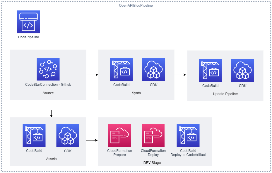
Figure 2 – CI/CD Pipeline
The stages defined include the following:
- Source stage: The pipeline is passed the source code contents from this stage.
- Synth stage: This stage consists of a Synth Action that synthesizes the CloudFormation templates for the application’s CDK stacks and compiles and builds the project Lambda API function.
- Update Pipeline stage: This stage checks the
OpenAPIBlogPipelinestack and reinitiates the pipeline when changes to its definition have been deployed. - Assets stage: The application’s CDK stacks produce multiple file assets (for example, zipped Lambda code) which are published to Amazon S3. Docker image assets are published to a managed CDK framework Amazon Elastic Container Registry (Amazon ECR) repository.
- DEV stage: The API’s CDK stack (
OpenApiBlogAPI) is deployed to a hypothetical development environment in this stage. A post stage deployment action is also defined in this stage. Through the use of a CDK ShellStep construct, a Bash script is executed that deploys a generated client Java Archive (JAR) for theWidgetAPI to CodeArtifact. The script employs the OpenAPI Generator project for this purpose:
CodeBuildStep codeArtifactStep = CodeBuildStep.Builder.create("CodeArtifactDeploy")
    .input(pipelineSource)
    .commands(Arrays.asList(
           	"echo $REPOSITORY_DOMAIN",
           	"echo $REPOSITORY_NAME",
           	"export CODEARTIFACT_TOKEN=`aws codeartifact get-authorization-token --domain $REPOSITORY_DOMAIN --query authorizationToken --output text`",
           	"export REPOSITORY_ENDPOINT=$(aws codeartifact get-repository-endpoint --domain $REPOSITORY_DOMAIN --repository $REPOSITORY_NAME --format maven | jq .repositoryEndpoint | sed 's/\\\"//g')",
           	"echo $REPOSITORY_ENDPOINT",
           	"cd api",
           	"wget -q https://repo1.maven.org/maven2/org/openapitools/openapi-generator-cli/5.4.0/openapi-generator-cli-5.4.0.jar -O openapi-generator-cli.jar",
     	          "cp ./maven-settings.xml /root/.m2/settings.xml",
        	          "java -jar openapi-generator-cli.jar batch openapi-generator-config.yaml",
                    "cd client",
                    "mvn --no-transfer-progress deploy -DaltDeploymentRepository=openapi--prod::default::$REPOSITORY_ENDPOINT"
))
      .rolePolicyStatements(Arrays.asList(codeArtifactStatement, codeArtifactStsStatement))
.env(new HashMap<String, String>() {{
      		put("REPOSITORY_DOMAIN", codeArtifactDomainName);
            	put("REPOSITORY_NAME", codeArtifactRepositoryName);
       }})
      .build();
Running the project
To run this project, you must install the AWS CLI v2, the AWS CDK Toolkit CLI, a Java/JDK 11 runtime, Apache Maven, Docker, and a Git client. Furthermore, the AWS CLI must be configured for a user who has administrator access to an AWS Account. This is required to bootstrap the CDK in your AWS account (if not already completed) and provision the required AWS resources.
To build and run the project, perform the following steps:
- Fork the OpenAPI blog project in GitHub.
- Open the AWS Console and create a connection to GitHub. Note the connection’s ARN.
- In the Console, navigate to AWS CodeArtifact and create a domain and repository. Note the names used.
- From the command line, clone your forked project and change into the project’s directory:
git clone https://github.com/<your-repository-path>
cd <your-repository-path>- Edit the CDK JSON file at
cdk/cdk.jsonand enter the details:
"RepositoryString": "<your-github-repository-path>",
"RepositoryBranch": "<your-github-repository-branch-name>",
"CodestarConnectionArn": "<connection-arn>",
"CodeArtifactDomain": "<code-artifact-domain-name>",
"CodeArtifactRepository": "<code-artifact-repository-name>"
Please note that for setting configuration values in CDK applications, it is recommend to use environment variables or AWS Systems Manager parameters.
- Commit and push your changes back to your GitHub repository:
git push origin main- Change into the
cdkdirectory and bootstrap the CDK in your AWS account if you haven’t already done so (enter “Y” when prompted):
cd cdk
cdk bootstrap- Deploy the CDK pipeline stack (enter “Y” when prompted):
cdk deploy OpenAPIBlogPipelineOnce the stack deployment completes successfully, the pipeline OpenAPIBlogPipeline will start running. This will build and deploy the API and its associated resources. If you open the Console and navigate to AWS CodePipeline, then you’ll see a pipeline in progress for the API.
Once the pipeline has completed executing, navigate to AWS CloudFormation to get the output values for the DEV-OpenAPIBlog stack deployment:
- Select the
DEV-OpenAPIBlogstack entry and then select the Outputs column. Record the REST_URL value for the key that begins withOpenAPIBlogRestAPIEndpoint. - Record the CLOUDFRONT_URL value for the key
OpenAPIBlogCloudFrontURL.
The API ping method at https://<REST_URL>/ping can now be invoked using your browser or an API development tool like Postman. Other API other methods, as defined by the OpenApi specification, are also available for invocation (For example, GET https://<REST_URL>/widgets).
To view the generated API documentation, open a browser at https://< CLOUDFRONT_URL>.
The following figure shows the API documentation website that has been auto-generated from the API’s OpenAPI specification. The documentation includes code snippets for using the API from multiple programming languages.
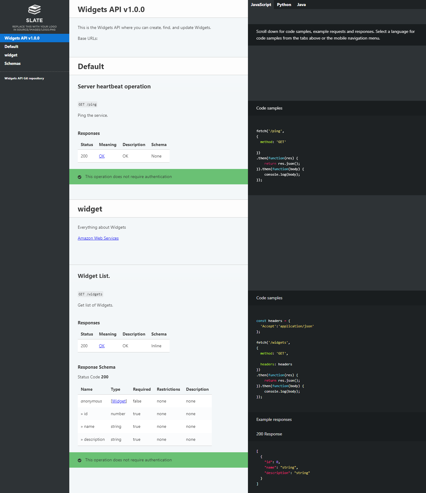
Figure 3 – Auto-generated API documentation
To view the generated API client code artifact, open the Console and navigate to AWS CodeArtifact. The following figure shows the generated API client artifact that has been published to CodeArtifact.
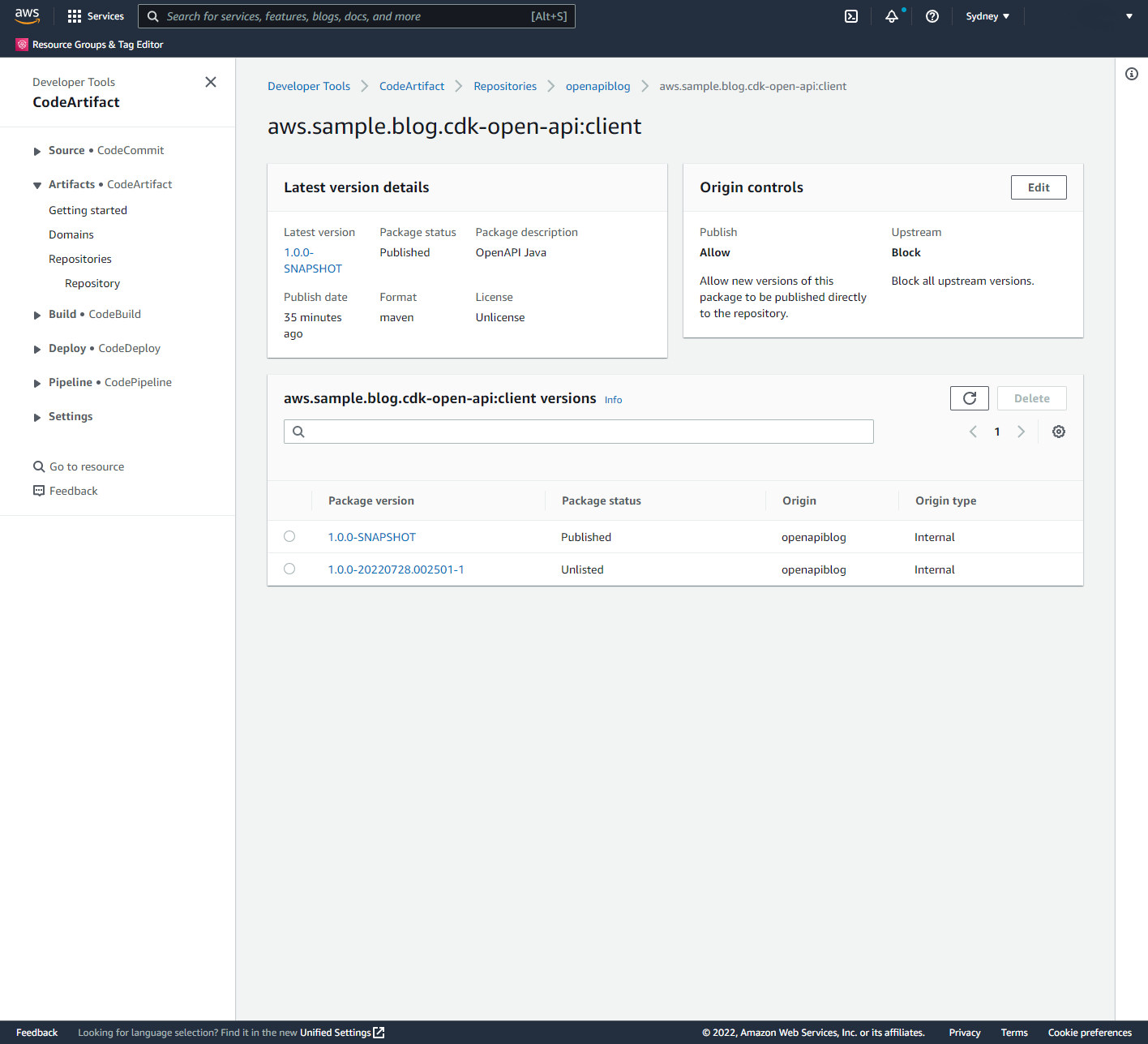
Figure 4 – API client artifact in CodeArtifact
Cleaning up
- From the command change to the
cdkdirectory and remove the API stack in the DEV stage (enter “Y” when prompted):
cd cdk
cdk destroy OpenAPIBlogPipeline/DEV/OpenAPIBlogAPI- Once this has completed, delete the pipeline stack:
cdk destroy OpenAPIBlogPipeline- Delete the S3 bucket created to support pipeline operations. Open the Console and navigate to Amazon S3. Delete buckets with the prefix
openapiblogpipeline.
Conclusion
This post demonstrates the use of the AWS CDK to deploy a RESTful API defined by the OpenAPI/Swagger specification. Furthermore, this post describes how to use the AWS CDK to auto-generate API documentation, publish this documentation to a web site hosted on Amazon S3, auto-generate API client libraries or SDKs, and publish these artifacts to an Apache Maven repository hosted on CodeArtifact.
The solution described in this post can be improved by:
- Building and pushing the API documentation Docker image to Amazon ECR, and then using this image in CodePipeline API pipelines.
- Creating stages for different environments such as TEST, PREPROD, and PROD.
- Adding integration testing actions to make sure that the API Deployment is working correctly.
- Adding Manual approval actions for that are executed before deploying the API to PROD.
- Using CodeBuild caching of artifacts including Docker images and libraries.
About the author:
EFF: Code, Speech, and the Tornado Cash Mixer
Post Syndicated from original https://lwn.net/Articles/905663/
The Electronic Frontier Foundation has announced that it is representing cryptography professor Matthew Green, who has chosen to republish the sanctioned Tornado Cash open-source code as a GitHub repository.
EFF’s most central concern about OFAC’s [US Office of Foreign Assets Control] actions arose because, after the SDN [Specially Designated Nationals] listing of “Tornado Cash,” GitHub took down the canonical repository of the Tornado Cash source code, along with the accounts of the primary developers, including all their code contributions. While GitHub has its own right to decide what goes on its platform, the disappearance of this source code from GitHub after the government action raised the specter of government action chilling the publication of this code.
In keeping with our longstanding defense of the right to publish code, we are representing Professor Matthew Green, who teaches computer science at the Johns Hopkins Information Security Institute, including applied cryptography and anonymous cryptocurrencies. Part of his work involves studying and improving privacy-enhancing technologies, and teaching his students about mixers like Tornado Cash. The disappearance of Tornado Cash’s repository from GitHub created a gap in the available information on mixer technology, so Professor Green made a fork of the code, and posted the replica so it would be available for study. The First Amendment protects both GitHub’s right to host that code, and Professor Green’s right to publish (here republish) it on GitHub so he and others can use it for teaching, for further study, and for development of the technology.